US6522785B1 - Classified adaptive error recovery method and apparatus - Google Patents
Classified adaptive error recovery method and apparatusDownload PDFInfo
- Publication number
- US6522785B1 US6522785B1US09/405,819US40581999AUS6522785B1US 6522785 B1US6522785 B1US 6522785B1US 40581999 AUS40581999 AUS 40581999AUS 6522785 B1US6522785 B1US 6522785B1
- Authority
- US
- United States
- Prior art keywords
- class
- data
- input signal
- motion vector
- deteriorated
- Prior art date
- Legal status (The legal status is an assumption and is not a legal conclusion. Google has not performed a legal analysis and makes no representation as to the accuracy of the status listed.)
- Expired - Fee Related
Links
Images


Classifications
- G—PHYSICS
- G06—COMPUTING OR CALCULATING; COUNTING
- G06T—IMAGE DATA PROCESSING OR GENERATION, IN GENERAL
- G06T5/00—Image enhancement or restoration
- G06T5/20—Image enhancement or restoration using local operators
- G—PHYSICS
- G06—COMPUTING OR CALCULATING; COUNTING
- G06T—IMAGE DATA PROCESSING OR GENERATION, IN GENERAL
- G06T5/00—Image enhancement or restoration
- G06T5/77—Retouching; Inpainting; Scratch removal
- G—PHYSICS
- G06—COMPUTING OR CALCULATING; COUNTING
- G06T—IMAGE DATA PROCESSING OR GENERATION, IN GENERAL
- G06T7/00—Image analysis
- G06T7/20—Analysis of motion
- G06T7/223—Analysis of motion using block-matching
- G06T7/231—Analysis of motion using block-matching using full search
- G—PHYSICS
- G06—COMPUTING OR CALCULATING; COUNTING
- G06T—IMAGE DATA PROCESSING OR GENERATION, IN GENERAL
- G06T2207/00—Indexing scheme for image analysis or image enhancement
- G06T2207/10—Image acquisition modality
- G06T2207/10016—Video; Image sequence
- G—PHYSICS
- G06—COMPUTING OR CALCULATING; COUNTING
- G06T—IMAGE DATA PROCESSING OR GENERATION, IN GENERAL
- G06T2207/00—Indexing scheme for image analysis or image enhancement
- G06T2207/20—Special algorithmic details
- G06T2207/20048—Transform domain processing
- G06T2207/20052—Discrete cosine transform [DCT]
- G—PHYSICS
- G06—COMPUTING OR CALCULATING; COUNTING
- G06T—IMAGE DATA PROCESSING OR GENERATION, IN GENERAL
- G06T2207/00—Indexing scheme for image analysis or image enhancement
- G06T2207/20—Special algorithmic details
- G06T2207/20048—Transform domain processing
- G06T2207/20056—Discrete and fast Fourier transform, [DFT, FFT]
- G—PHYSICS
- G06—COMPUTING OR CALCULATING; COUNTING
- G06T—IMAGE DATA PROCESSING OR GENERATION, IN GENERAL
- G06T2207/00—Indexing scheme for image analysis or image enhancement
- G06T2207/20—Special algorithmic details
- G06T2207/20172—Image enhancement details
- G06T2207/20201—Motion blur correction
Definitions
- This inventionrelates generally to the processing of image, sound or other correlated signals, and more particularly, to a method, apparatus, and article of manufacture for restoring a deteriorated signal to an undeteriorated signal.
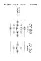
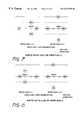
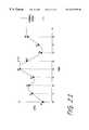
- FIG. 1Ashows a conventional error recovery block diagram.
- FIG. 1Buses neighboring data, which are shown in FIG. 1B, spatial inclinations of the target data are detected.
- the inclinations regarding four directionsare evaluated according to the formulae which are shown in FIG. 1 C.
- An interpolation filteris chosen where the inclination value, E i , is the smallest among four values.
- a motion factoris also evaluated for error recovery.
- a selected spatial filteris used for error recovery.
- the previous frame data at the same location as the target dataare used for error recovery. This evaluation is performed in the evaluation block of FIG. 1 A.
- the conventional error recovery process shown in FIGS. 1A-1Cmay cause many serious degradations on changing data, especially on object edges. Actual signal distribution typically varies widely, so these problems are likely to occur. Therefore, there is a need for a way to restore a deteriorated signal to an undeteriorated signal which minimizes degradations on changing data.
- the present inventionprovides a method, apparatus, and article of manufacture for restoring a deteriorated signal to an undeteriorated signal.
- a deteriorated signalconsists of a plurality of deteriorated and undeteriorated data points. For each deteriorated data point, a plurality of class types is created based upon characteristics of the area containing the deteriorated data point. The data point is classified with respect to one of the plurality of class types and assigned a corresponding input signal class. The undeteriorated signal is generated by adaptive filtering of the input signal in accordance with the input signal classification results. More than one classification method may optionally be used to create the plurality of class types. Created classes may include a motion class, an error class, a spatial class or a spatial activity class.
- An adaptive class tap structuremay optionally be used to create the plurality of class types.
- An adaptive filter tap structuremay optionally be used base on the corresponding plurality of class types.
- Filter tap expansionmay optionally be used to reduce the number of filter coefficients.
- the deteriorated input signalis modified by preprocessing peripheral erroneous data.
- a spatial classmay optionally be modified according to spatial symmetry.
- FIGS. 1A-1Cshow a conventional error recovery method, filter tap, and correspondence between inclination value and interpolation filter
- FIGS. 2A-2Eshow a classified adaptive error recovery method and class compatible with an embodiment of the present invention
- FIGS. 2F-2Ishow motion compensation preprocessing compatible with an embodiment of the present invention
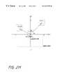
- FIG. 2Jshows a motion vector field compatible with an embodiment of the present invention
- FIG. 3shows a motion class tap compatible with an embodiment of the present invention
- FIG. 4shows an error class tap compatible with an embodiment of the present invention
- FIG. 5shows an adaptive spatial class tap compatible with an embodiment of the present invention
- FIG. 6shows an adaptive spatial class tap (error class 0 ) compatible with an embodiment of the present invention
- FIG. 7shows an adaptive spatial class tap (error class 1 ) compatible with an embodiment of the present invention
- FIG. 8shows an adaptive spatial class tap (error class 2 ) compatible with an embodiment of the present invention
- FIG. 9shows an adaptive spatial class tap (error class 3 ) compatible with an embodiment of the present invention.
- FIG. 10shows an adaptive filter tap compatible with an embodiment of the present invention
- FIG. 11shows a motion class adaptive filter tap compatible with an embodiment of the present invention
- FIG. 12shows a motion class adaptive filter tap (error class 0 ) compatible with an embodiment of the present invention
- FIG. 13shows a motion class adaptive filter tap (error class 1 ) compatible with an embodiment of the present invention
- FIG. 14shows a motion class adaptive filter tap (error class 2 ) compatible with an embodiment of the present invention
- FIG. 15shows a motion class adaptive filter tap (error class 3 ) compatible with an embodiment of the present invention
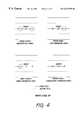
- FIG. 16shows a preprocessing algorithm compatible with an embodiment of the present invention
- FIG. 17shows a motion tap and stationary tap preprocessing algorithm compatible with an embodiment of the present invention
- FIGS. 18A and 18Bshow system block diagrams compatible with an embodiment of the present invention
- FIG. 19shows coefficient memory contents compatible with an embodiment of the present invention
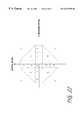
- FIG. 20shows an ADRC class reduction based on a 4-tap 1-bit ADRC compatible with an embodiment of the present invention.
- FIG. 21shows an example of audio signal adaptive classification compatible with an embodiment of the present invention.
- the present inventionprovides a method, apparatus, and article of manufacture for restoring a deteriorated signal to an undeteriorated signal using classified adaptive error recovery.
- Target datais the particular data of the deteriorated signal whose value is to be determined or estimated.
- Classified adaptive error recoveryis the technology which utilizes classified adaptive filter processing. A proper classification with respect to the deteriorated input signal is performed according to the input signal characteristics. An adaptive filter is prepared for each class prior to error recovery processing.
- More than one classification methodmay optionally be used to generate the plurality of classes.
- Generated classesmay include a motion class, an error class, a spatial activity class or a spatial class.
- An adaptive class tap structuremay optionally be used to generate the plurality of classes.
- An adaptive filter tap structuremay optionally be used according to the class which is detected in each deteriorated input signal.
- the adaptive filter tap structuremay optionally be expanded based upon multiple taps. The number of filter coefficients that must be stored can be reduced by allocating the same coefficient to multiple taps. This process is referred to as filter tap expansion.
- the deteriorated input signalmay optionally be modified by preprocessing peripheral erroneous data.
- a spatial classmay optionally be eliminated according to a spatial class elimination formula.
- the present inventioncan be applied to any form of correlated data, including without limitation photographs or other two-dimensional static images, holograms, or other three-dimensional static images, video or other two-dimensional moving images, three-dimensional moving images, a monaural sound stream, or sound separated into a number of spatially related streams, such as stereo.
- the term valuein one embodiment, may refer to a component within a set of received or generated data.
- a data pointis a position, place, instance, location or range within data.
- an adaptive class tap structureis an adaptive structure for class tap definition used in multiple classification.
- a spatial class, a motion class and an error classmay be used to define the structure.
- An adaptive filter tap structureis an adaptive structure for filter tap definition based upon a corresponding class.
- a classmay be defined based on one or more characteristics of the target data.
- a classmay also be defined based on one or more characteristics of the group containing the target data.
- a class IDis a specific value within the class that is used to describe and differentiate the target data from other data with respect to a particular characteristic.
- a class IDmay be represented by a number, a symbol, or a code within a defined range.
- a parametermay be used as a predetermined or variable quantity that is used in evaluating, estimating, or classifying the data.
- the particular motion class ID of a target datacan be determined by comparing the level of motion quantity in the block containing the target data against a parameter which can be a pre-determined threshold.
- the original datamay be estimated with neighboring data using the classified adaptive error recovery method, which classifies and filters the data.
- data that is spatially close to error datamay have a greater contribution to estimating the correct value because of the high spatial correlation. If temporal tap data is introduced for classification and filtering in motion areas, the estimation performance may be decreased because of lower spatial correlation caused by the motion.
- a preprocessing stepcan introduce motion compensation before classifying the adaptive error recovery.
- motion compensation preprocessing for erroneous datamay be performed before the classified adaptive error recovery method.
- the motion compensation preprocessinghas two components. One is motion vector detection. The other is shifting the motion affected data (hereinafter referred to as the “memorized data”) according to the motion vector.
- the fundamental structure for performing the preprocessing methodis shown in FIG. 2 A.
- the motion compensation structurecomprises two processing elements, a motion vector detector 280 , and a memory 290 .
- the motion vectoris detected by the motion vector detector 280 by examining the temporal correlation. A number of conventional methods may be used.
- the neighboring image data usede.g., an image of a prior field or frame stored in memory, 290 is shifted.
- the neighboring datamay be data that is temporally prior or subsequent, as well as data that is spatially adjacent or non-adjacent data, e.g. frames of data.
- the shift operationis accomplished by shifting the memory addresses accessed to form the motion compensated data.
- the motion compensated datais provided for the following classified adaptive error recovery.
- the motion compensation preprocessingcan greatly improve the estimation performance of the classified adaptive error recovery process, because the motion area data can provide a higher correlation. As a result, improved error recovered images can be achieved by this method.
- Input data and corresponding error flagsare input to the system.
- a motion vectoris detected from the input data at 280 .
- Motion vector classificationis performed at 205 .
- Filter tap dataare chosen at 213 based on the motion vector class.
- Error recovery filteringis performed at 209 with tap data and filter coefficients selected from the coefficient memory 207 . Error recovered data and error free input data are selected at 211 recording to the error flag, which produces the output of the system.
- the motion vector detector 280 shown in FIG. 2Adetermines a motion vector in an image. Examples of motion vectors are shown in FIGS. 2F and 2G.
- the motion vector in FIG. 2Fis the line segment that begins at point (i 0 , j 0 ) and ends at point (i a , j a ).
- the moving part of the imageis duplicated in its new location.
- the memorystores the prior frame data with image 250 in the first position. After the motion vector MV is detected, the position of image 250 within memory is shifted to the second position.
- the motion vectormay be detected by a variety of techniques. Three examples of methods for detecting a motion vector include phase correlation, gradient descent, and block matching.
- phase correlation techniqueis as follows.
- F( ⁇ 1 , ⁇ 2 )is defined as the Fourier Transform of an image point f(x 1 , x 2 ).
- the Fourier Transform of f(x 1 + ⁇ 1 , x 2 + ⁇ 2 )can be e j2 ⁇ ( ⁇ 1 ⁇ 1+ ⁇ 2 ⁇ 2) * F( ⁇ 1 , ⁇ 2 ).
- the motion vector quantity represented by ⁇ 1 and ⁇ 2can be estimated by calculating the Fourier Transform of both f(x 1 , x 2 ) and f(x 1 + ⁇ 1 , x 2 + ⁇ 2 ), and then estimating the multiplicative factor that relates the two.
- the error function for an image e( ⁇ )may be computed as f(x+v ⁇ ) ⁇ f(x), where v represents the real motion vector and ⁇ represents an estimate of v.
- the gradient descent techniqueis used to minimize e( ⁇ ).
- the minimum of e( ⁇ )is representative of the motion vector.
- One embodiment of the block matching techniquedetects a motion vector using pattern matching. For example, at each search point (e.g. point of the image), the temporal correlation is measured. For example, a correlation value corresponding to the summed absolute temporal differences between the current block data and the corresponding past block data at each point is generated. After generating the values at all or some points, the motion vector with the smallest value is chosen. This is representative of the highest correlated point presenting a motion vector.
- FIG. 2 HAn original block area is defined as shown in FIG. 2 H.
- the block datais defined as f(i 0 +X, j 0 +Y).
- a searching point f(i, j)is detected.
- the equation E ⁇ ( i , j )⁇ x ⁇ ⁇ y ⁇ ⁇ f ⁇ ( i 0 + X , j 0 + Y ) - f ⁇ ( i + X , j + Y )
- the motion vector MVmay then be determined as min ⁇ E(i, j) ⁇ ; ⁇ I ⁇ i ⁇ I; ⁇ J ⁇ j ⁇ J.
- FIG. 21shows two fields in a frame during multiple time periods.
- Field 260 during time period T 3contains error data.
- This error datais highly correlated with pixel 262 in field 264 from time period T 2 .
- the non-stationary datais highly correlated in the spatial and temporal domain.
- the filtering performanceis improved by using prior field data with the motion compensation preprocessing.
- classified adaptive error recoveryclassifies the error distribution.
- errorsmay be very hard to correct when the data is non-stationary data.
- the ability to correct errorsis greatly improved using motion compensation preprocessing.
- the advantages of performing motion compensation preprocessing with the classified adaptive error recovery processinclude classification quality improvement, because there is a high correlation of temporal data.
- the spatial (pattern) classification and the spatial activity classificationare also improved.
- Adaptive filteringis also improved due to the high correlation of temporal data by execution of motion compensation preprocessing.
- a multiple classmay be used as a collection of specific values or sets of values used to describe at least two different characteristics of the target data.
- a multiple classmay be defined to be a combination of at least two different classes.
- a multiple classmay be defined to be a combination of an error class, a motion class, and a spatial class such as an ADRC class.
- the multiple class IDcan be used as the memory address to locate the proper filter coefficients and other information that are used to determine or estimate the value of the target data.
- a simple concatenation of different class IDs in the multiple class IDis used as the memory address.
- a multiple classification schemeis a way of classifying the target data with respect to more than one characteristic of the target data in order to more accurately determine or estimate the value of the target data.
- An error classis a collection of specific values used to describe the various distribution patterns of erroneous data in the neighborhood of the target data.
- an error classis defined to indicate which adjacent data to the target data is erroneous.
- An error class IDis a specific value within the error class used to describe a particular distribution pattern of erroneous data in the neighborhood of the target data. For example, an error class ID of “0” may be defined to indicate that there is no erroneous data to the left and to the right of the target data; an error class ID of “1” may be defined to indicate that the data to the left of the target data is erroneous, etc.
- a filteris a mathematical process, function or mask for selecting a group of data.
- a motion classis a collection of specific values used to describe the motion characteristic of the target data.
- the motion classis defined based on the different levels of motion of the block containing the target data, for example, no motion in the block, little motion in the block, or large motion in the block.
- a motion class IDis a specific value within the motion class used to indicate a particular level of motion quantity of the target data. For example, motion class ID of “0” may be defined to indicate no motion, motion class ID of “3” may be defined to indicate large motion.
- a motion vector classis a collection of specific values used to describe the directional motion characteristic of the target data.
- the motion vector classis defined based on the different directions of motion of the block containing the target data, for example, vertical, horizontal, or diagonal.
- a motion vector class IDis a specific value within the motion vector class used to indicate a particular direction of motion of the target data.
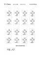
- FIG. 2Jshows an embodiment of motion vector class ID.
- motion vector class ID of “1”may be defined to indicate small horizontal motion
- motion vector class ID of “4”may be defined to indicate large vertical motion.
- Motion vector class “0”may define very little or no motion.
- Motion vector class “7”may define very fast motion without specifying a particular direction. The degradation for the very fast motion cannot be detected, therefore, a simple motion class such as “7” may be used.
- FIG. 2Jis only one example of possible motion vector classifications.
- the classificationsmay vary by size and shape of area corresponding to a particular value and/or number of possible classifications.
- a symmetrical structureis used to reduce the number of motion vector classifications, which reduces the number of filters.
- non-symmetrical motion vector classificationsmay also be used.
- the vertical direction of the motionmay correspond to a tilting object or a tilting picture. This kind of picture may be separated from the horizontal motion of the picture, especially for interlaced images.
- motion vector classificationprovides several advantages, including identification of the motion direction of an image, and the separation of tilting images from panning images and horizontally move objects from vertically moving objects.
- a video cameralooking at relatively stationary objects. The camera can be tilted up or down or panned left or right. That's analogous to a stationary camera and object, moving down or up (reversed) or right or left.
- the motion vector classificationis also utilized in an adaptive filter tap structure based on the motion vector, and therefore may improve the estimation accuracy over motion classification alone.
- a spatial classis a collection of specific values used to describe the spatial characteristic of the target data. For example, spatial classification of the data may be determined using Adaptive Dynamic Range Coding (ADRC), Differential Pulse Code Modulation (DPCM), Vector Quantization (VQ), Discrete Cosine Transform (DCT), etc.
- a spatial class IDis a specific value within the spatial class used to describe the spatial pattern of the target data in the group or block containing the target data.
- an ADRC classis a spatial class defined by the Adaptive Dynamic Range Coding method.
- An ADRC class IDis a specific value within the ADRC class used to describe the spatial pattern of the data distribution in the group or block containing the target data.
- a classis a collection of specific values used to describe certain characteristics of the target data.
- a variety of different types of classesexist, for example, a motion class, a spatial class, an error class, a spatial activity class, etc.
- the present inventionprovides a method and apparatus for adaptive processing that generates data corresponding to a set of one or more data classes. This process is known as “classification”. Classification can be achieved by various attributes of signal distribution. For example, Adaptive Dynamic Range Coding (ADRC) may be used for generation of each class as a spatial class, but it will be recognized by one of ordinary skill in the art that other classes, including a motion class, an error class, and a spatial activity class may be used with the present invention without loss of generality.
- a spatial activity classis a collection of specific values used to describe the spatial activity characteristic of the target data. For example, spatial activity classification of the data may be determined using the dynamic range, the standard deviation, the Laplacian value or the spatial gradient value.
- each filteris represented by a matrix of filter coefficients which are applied to the data.
- the filter coefficientscan be generated by a training process, an example of which is described subsequently, that occurs as a preparation process prior to filtering.
- the filter coefficientscan be stored in a random access memory (RAM), shown in FIG. 2A at 207 .
- Target input data 201can be accompanied with error flag data 203 .
- Error flag datacan indicate locations within the data that contain erroneous pixels.
- an ADRC classis generated for each input target data in classification block 205 , filter coefficients corresponding to each class ID are output from the coefficient memory block 207 , and filtering is executed with input data 201 and the filter coefficients in the filter block 209 .
- the filtered datamay correspond to an error recovered result.
- switching between error recovered data and error free dataoccurs according to the error flag data 203 .
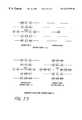
- FIG. 2Can example is shown where the number of class taps is four.
- 16 class IDsare available as given by [formula 3], shown below.
- ADRCis realized by [formula 2], shown below.
- Detecting a local dynamic range (DR)is given by [formula 1], shown below,
- ccorresponds to an ADRC class ID
- DRrepresents the dynamic range of the four data area
- MAXrepresents the maximum level of the four data
- MINrepresents the minimum level of the four data
- qiis the ADRC encoded data, also referred to as a Q code
- Qis the number of quantization bits.
- the ⁇ . ⁇ operatorrepresents a truncation operation.
- This processis one type of spatial classification, but it will be recognized by one of ordinary skill in the art that other examples of spatial classification, including Differential PCM, Vector Quantization and Discrete Cosine Transform may be used with the present invention without loss of generality. Any method may be used if it can classify a target data distribution.
- each adaptive filterhas 12 taps.
- Filter coefficientscan be generated for each class ID by a training process that occurs prior to the error recovery process.
- trainingmay be achieved according to the following criterion.
- X, W, and Yare, for example, the following matrices:
- Xis the input data matrix defined by [formula 6]
- Wis the coefficient matrix defined by [formula 7]
- Ycorresponds to the target data matrix defined by [formula 8].
- X( x 11 x 12 ⁇ x 1 ⁇ n x 21 x 22 ⁇ x 2 ⁇ n ⁇ ⁇ ⁇ ⁇ x m1 x m2 ⁇ x mn ) [formula 6]
- W( w 1 w 2 ⁇ w n ) [formula 7]
- Y( y 1 y 2 ⁇ y m ) [formula 8]
- the coefficient w ican be obtained according to [formula 5], so that estimation errors against target data are minimized.
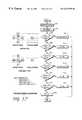
- FIG. 2 EA flow diagram of an embodiment of the present invention is shown in FIG. 2 E.
- the flow chart of FIG. 2Eshows the basic processing stream for generating an undeteriorated signal from the deteriorated input signal.
- the preprocessing for a peripheral erroneous pixelis performed.
- each classification regarding the deteriorated input signalis executed to generate a class ID.
- Some class tapsare selected adaptively according to another class ID. Multiple classification may be executed, such as motion classification, error classification, spatial activity classification and spatial classification.
- the classification schemecan be defined during system design, where the classification scheme, the number of classes, and other specification are decided for the target data.
- the design stagemay include, among others, considerations of system performance and hardware complexity.
- multiple classificationgenerates a multiple class ID with a plurality of class IDs which are generated by various classification at step 217 .
- filter tapsare adaptively selected according to the multiple class ID which is generated at step 219 .
- the filter tap structureis adaptively expanded according to the multiple class ID which is generated at step 219 .
- the number of filter coefficients that must be storedcan be reduced by allocating the same coefficient to multiple taps. This process is referred to as filter tap expansion.
- filter coefficientsare selected according to the multiple class ID which is generated at step 219 .
- filtering with respect to the deteriorated input signalis executed to generate an undeteriorated signal. Filter coefficients are selected adaptively according to the multiple class ID which is generated in step 219 .
- a three dimensional DRC processmay be used to realize spatio-temporal classification, because simple waveform classifications such as a two dimensional ADRC process typically cannot structurally achieve separation for general motion pictures in the class of FIG. 2 C. If both stationary and motion areas are processed in the same class ID, error recovery quality is degraded because of differences in characteristics of the two areas.
- motion classification or motion vector classificationin addition to spatial classification, may also be used to provide compact definition of temporal characteristics.
- multiple classificationmay be added to the classified adaptive error recovery method.
- classessuch as a motion class, a motion vector class, an error class, a spatial activity class and a spatial class explained above.
- the combination of one or more of these different classification methodscan also improve classification quality.
- FIG. 3shows an example of motion class tap structures. [It would be helpful to include an example of motion vector class tap structure?].
- the exampleshows eight taps in neighborhood of the target error data.
- the eight tap accumulated temporal differencecan be evaluated according to [formula 9], shown below, and is classified to four kinds of motion classes by thresholding based on [formula 10], shown below.
- th 0is equal to 3
- th 1is equal to 8
- th 2is equal to 24.
- fdrepresents an accumulated temporal difference
- X irepresents motion class tap data of the current frame
- X′ irepresents the previous frame tap data corresponding to the current frame
- mcrepresents a motion class ID.
- Three thresholds, th 0 , th 1 , th 2can be used for this motion classification.
- an error classcan be used in conjunction with the classified adaptive error recovery method. This classification is achieved according to the erroneous data distribution pattern in neighborhood of the target data, examples of which are shown in FIG. 4 .
- This examplehas four error classes: an independent error case, a left error case, a right error case, and a three consecutive error case.
- ADRC classificationgenerates 16 kinds of ADRC class IDs, where motion and error classification generate four kinds of class IDs, respectively.
- the number of class IDsequals 16 ⁇ 4 ⁇ 4, or 256.
- Classificationmay be realized by representing each signal characteristic. Multiple classification can define a suitable class, the class ID, regarding the erroneous target data by combining different classification characteristics.
- an adaptive class tap structurecan be used in conjunction with the classified adaptive error recovery method.
- FIG. 5shows one example of motion class adaptive spatial class tap structures. Intra-frame taps can be chosen in a stationary or a slow motion area. Intra-field taps are typically used for larger motion areas. Suitable spatial classification is achieved by this adaptive processing.
- Spatial class tapsare typically selected according to a motion and an error class.
- the erroneous data distributionis taken into account for the spatial class tap definition.
- the neighboring erroneous datais typically not introduced to the spatial classification. By this definition, only valid data is used and the classification accuracy is improved.
- an adaptive filter tap structure based on a corresponding classcan be used in conjunction with the classified adaptive error recovery method.
- FIG. 10shows one example of an adaptive filter tap structures based on an error class.
- the filter tap structure regarding the target datais typically defined adaptively, preferably avoiding damaged data in neighborhood. Damaged data is not chosen for filtering.
- An adaptive filter tap structurecan be also defined according to motion class, an example of which is shown in FIG. 11 .
- motion class 0corresponds to stationary areas, but motion class 3 corresponds to large motion areas.
- Motion classes 1 and 2correspond to intermediate motion areas.
- intra-frame tapsare used as shown in FIG. 11 .
- previous frame data at the target data locationmay be used for error recovery filtering. These areas correspond to motion class 0 and 1 .
- each filtertypically has an intra-field taps structure, which is also shown in FIG. 11 . As shown by the example in FIG. 11, previous frame data is not introduced, and thus weakly correlated data is ignored. Filtering quality is typically improved by intra-field taps in such cases.
- FIG. 12shows an example of motion and error class adaptive filter tap structures.
- FIGS. 10 and 11represent error and motion class adaptive filter taps, respectively.
- the example shown in FIG. 12illustrates both adaptive structures with error class 0 , which is the independent error case.
- Upper adaptive characteristicsare also shown in this example.
- FIG. 13corresponds to error class 1
- FIG. 14corresponds to error class 2
- FIG. 15corresponds to error class 3 .
- filter tap expansion by allocating the same coefficient to plural tapscan be used in conjunction with the classified adaptive error recovery method.
- Filter tap expansionis also shown by the structures in FIGS. 12-15.
- the filter tap structurehas four of the same coefficient taps with motion class 3 in FIG. 12 .
- some tap coefficientscan be replaced with the same coefficient.
- the example shown in FIG. 12has four W 3 coefficients that are allocated at horizontally and vertically symmetric locations.
- 14 coefficientscan cover 18 tap areas.
- This reduction methodcan typically reduce the need for coefficient memory and filtering hardware such as adders and multipliers.
- the expansion tap definitionmay be achieved by evaluation of coefficient distribution and visual results.
- preprocessing for peripheral erroneous datacan be used in conjunction with the classified adaptive error recovery method.
- suitable datais necessary at peripheral error locations of filter taps.
- FIG. 16One example of this preprocessing is shown by the flow diagram of FIG. 16 . If at steps 1601 , 1605 , or 1609 there is erroneous data at a peripheral location of the target data, at steps 1603 , 1607 , 1611 the erroneous data is replaced with horizontal processed data in the case of no horizontal errors. If at steps 1613 , 1617 , or 1621 there are three consecutive horizontal errors, at steps 1615 , 1619 , or 1623 vertical processing is applied for generating preprocessed data. In all erroneous cases around the intra-frame data of this example, previous frame data is introduced for error processing, at step 1625 .
- FIG. 17shows another preprocessing example that uses a motion adaptive process for preprocessing.
- motion quantityis detected at the motion detection step 1701 .
- an averaged motion quantityis calculated by averaging summed motion quantity with the number of error free data at the next step.
- Motion or stationary tapsare chosen at step 1703 according to a threshold value of the result of averaged motion quantity.
- processing steps 1705 through 1729are performed in a manner similar to steps 1601 through 1625 of FIG. 16 .
- the preprocessed datais generated according to these prioritized processes, and is introduced for error recovery filtering.
- spatial class reductioncan be used in conjunction with the classified adaptive error recovery.
- ccorresponds to the ADRC class ID
- qiis the quantized data
- Qis the number of quantization bits based on [formula 1] and [formula 2].
- [formula 11]corresponds to a 1's complement operation in binary data of the ADRC code. This is related to the symmetric characteristics of each signal waveform. Because ADRC classification is a normalization of the target signal waveform, two waveforms which have the relation of 1's complement in each ADRC code can be classified in the same class ID. ADRC class IDs can typically be halved by this reduction process. An ADRC class reduction based on a 4-tap 1-bit ADRC is shown in FIG. 20 . In this example, applying [formula 11] gives eight ADRC class pairs. Each pair contains spatial symmetric patterns, and therefore the number of ADRC class IDs can be reduced by half by taking advantage of these symmetric patterns. The spatial class reduction technique can also be applied to other spatial classification techniques, including but not limited to DPCM and Block Truncation Coding (BTC).
- BTCBlock Truncation Coding
- FIG. 18 AAn overall system structure for one embodiment of the present invention, including all the processes described above, is shown in FIG. 18 A.
- Input data 1801 and corresponding error flags 1803are input to the system. Examining the error flags 1803 , the input data 1801 is preprocessed at 1805 .
- ADRC classificationis performed at 1807
- motion vector classificationis performed at 1809
- error classificationis performed at 1811 .
- ADRC class tapsare chosen adaptively according to the error motion vector class.
- Filter tap dataare chosen at 1813 based on the error and motion vector class.
- Error recovery filteringis performed at 1817 with tap data and filter coefficients selected from the coefficient memory 1815 corresponding to the ADRC class ID of 1807 , the motion vector class ID of 1809 and the error class ID of 1811 .
- Error recovered data and error free input data 1817are selected at 1821 according to the error flag 1803 , which produces the output data 1823 of this system.
- FIG. 18Bshows an embodiment of a motion vector class generator 1809 .
- Motion vector detector 1839detects the motion vector using conventional methods such as the block matching method described above, for example.
- the motion vectoris detected for the target data.
- the motion class generator 1841may identify the vector as a 3 bit quantized characteristic for the motion vector, as shown in FIG. 2J, for example.
- the quantized datatherefore may represent the motion vector class data that is used to access the coefficient memory 1815 .
- the estimation performance in the error recovery processingcan be greatly improved by using the motion vector classification.
- FIG. 19shows an example of coefficient memory,contents. It has 4 ⁇ 4 ⁇ 8 or 128 class IDs according to the multiple classification scheme. Four categories are used for an error class, four categories are for a motion class, and eight categories are for an ADRC class, which are typically halved according to [formula 11]. Each class corresponds to each memory address in FIG. 19 . In this example, 14 coefficients are stored in each class ID address according to the filter definition, like FIGS. 12, 13 , 14 , 15 .
- FIG. 21shows an example of audio signal adaptive classification compatible with the present invention.
- An example audio signal 2101is monitored at one or more time points t 0 -t 8 .
- the level of the audio signal 2101 at time points t 0 -t 8is given by tap points X 0 -X 8 .
- the dynamic range of the audio signal 2101is given as the difference between the lowest level tap point X 0 and the highest level tap point X 4 .
- multiple classificationcan be applied with spatial classification like ADRC classification and spatial activity classification like dynamic range classification.
- Dynamic range classificationis performed by thresholding the dynamic range in a manner similar to the motion classification processing of [formula 10].
- motion classification, error classification and spatial classificationare referred to in multiple classification.
- Spatial activity classificationcan also be introduced to multiple classification for general applications such as video data.
- the standard deviation, the Laplacian value or the spatial gradient valuecan be introduced for spatial activity classification.
- the quality of data that is recovered due to errorsis improved by introducing the disclosed technologies to the classified adaptive error recovery method.
- the present inventionprovides a way to restore a deteriorated signal to an undeteriorated signal which minimizes degradations on changing data.
Landscapes
- Engineering & Computer Science (AREA)
- Physics & Mathematics (AREA)
- General Physics & Mathematics (AREA)
- Theoretical Computer Science (AREA)
- Multimedia (AREA)
- Computer Vision & Pattern Recognition (AREA)
- Image Analysis (AREA)
- Compression Or Coding Systems Of Tv Signals (AREA)
- Picture Signal Circuits (AREA)
- Control Of Metal Rolling (AREA)
- Complex Calculations (AREA)
Abstract
Description


Claims (62)
Priority Applications (6)
| Application Number | Priority Date | Filing Date | Title |
|---|---|---|---|
| US09/405,819US6522785B1 (en) | 1999-09-24 | 1999-09-24 | Classified adaptive error recovery method and apparatus |
| GB0208311AGB2371939B (en) | 1999-09-24 | 2000-08-22 | Classified adaptive error recovery method and apparatus |
| DE10085028TDE10085028T1 (en) | 1999-09-24 | 2000-08-22 | Method and device for classified adaptive troubleshooting |
| JP2001526799AJP4222753B2 (en) | 1999-09-24 | 2000-08-22 | Classification adaptive error recovery method and apparatus |
| AU67972/00AAU6797200A (en) | 1999-09-24 | 2000-08-22 | Classified adaptive error recovery method and apparatus |
| PCT/US2000/023035WO2001024105A1 (en) | 1999-09-24 | 2000-08-22 | Classified adaptive error recovery method and apparatus |
Applications Claiming Priority (1)
| Application Number | Priority Date | Filing Date | Title |
|---|---|---|---|
| US09/405,819US6522785B1 (en) | 1999-09-24 | 1999-09-24 | Classified adaptive error recovery method and apparatus |
Publications (1)
| Publication Number | Publication Date |
|---|---|
| US6522785B1true US6522785B1 (en) | 2003-02-18 |
Family
ID=23605383
Family Applications (1)
| Application Number | Title | Priority Date | Filing Date |
|---|---|---|---|
| US09/405,819Expired - Fee RelatedUS6522785B1 (en) | 1999-09-24 | 1999-09-24 | Classified adaptive error recovery method and apparatus |
Country Status (6)
| Country | Link |
|---|---|
| US (1) | US6522785B1 (en) |
| JP (1) | JP4222753B2 (en) |
| AU (1) | AU6797200A (en) |
| DE (1) | DE10085028T1 (en) |
| GB (1) | GB2371939B (en) |
| WO (1) | WO2001024105A1 (en) |
Cited By (14)
| Publication number | Priority date | Publication date | Assignee | Title |
|---|---|---|---|---|
| US20040135926A1 (en)* | 2003-01-02 | 2004-07-15 | Samsung Electronics Co., Ltd. | Progressive scan method used in display using adaptive edge dependent interpolation |
| US20040263684A1 (en)* | 2002-08-19 | 2004-12-30 | Tetsuro Tanaka | Image processing device and method, video display device, and recorded information reproduction device |
| US20070014554A1 (en)* | 2004-12-24 | 2007-01-18 | Casio Computer Co., Ltd. | Image processor and image processing program |
| US20070019107A1 (en)* | 2003-09-04 | 2007-01-25 | Koninklijke Philips Electronics N.V. | Robust de-interlacing of video signals |
| US20070164882A1 (en)* | 2006-01-13 | 2007-07-19 | Monro Donald M | Identification of text |
| US20070258654A1 (en)* | 2006-04-07 | 2007-11-08 | Monro Donald M | Motion assisted data enhancement |
| US20070282933A1 (en)* | 2006-06-05 | 2007-12-06 | Donald Martin Monro | Data coding |
| US20080205505A1 (en)* | 2007-02-22 | 2008-08-28 | Donald Martin Monro | Video coding with motion vectors determined by decoder |
| US20090003461A1 (en)* | 2007-06-28 | 2009-01-01 | Samsung Electronics Co., Ltd. | Error concealing method and apparatus adaptive to characteristics of blocks adjacent to lost block |
| US20100085224A1 (en)* | 2008-10-06 | 2010-04-08 | Donald Martin Monro | Adaptive combinatorial coding/decoding with specified occurrences for electrical computers and digital data processing systems |
| US20100085219A1 (en)* | 2008-10-06 | 2010-04-08 | Donald Martin Monro | Combinatorial coding/decoding with specified occurrences for electrical computers and digital data processing systems |
| US20100085218A1 (en)* | 2008-10-06 | 2010-04-08 | Donald Martin Monro | Combinatorial coding/decoding with specified occurrences for electrical computers and digital data processing systems |
| US20100085221A1 (en)* | 2008-10-06 | 2010-04-08 | Donald Martin Monro | Mode switched adaptive combinatorial coding/decoding for electrical computers and digital data processing systems |
| US9836831B1 (en)* | 2014-07-30 | 2017-12-05 | Google Inc. | Simulating long-exposure images |
Families Citing this family (1)
| Publication number | Priority date | Publication date | Assignee | Title |
|---|---|---|---|---|
| US6898328B2 (en) | 2002-10-23 | 2005-05-24 | Sony Corporation | Method and apparatus for adaptive pixel estimation under high error rate conditions |
Citations (135)
| Publication number | Priority date | Publication date | Assignee | Title |
|---|---|---|---|---|
| US3311879A (en) | 1963-04-18 | 1967-03-28 | Ibm | Error checking system for variable length data |
| US3805232A (en) | 1972-01-24 | 1974-04-16 | Honeywell Inf Systems | Encoder/decoder for code words of variable length |
| US4361853A (en) | 1977-04-14 | 1982-11-30 | Telediffusion De France | System for reducing the visibility of the noise in television pictures |
| US4381519A (en) | 1980-09-18 | 1983-04-26 | Sony Corporation | Error concealment in digital television signals |
| US4419693A (en) | 1980-04-02 | 1983-12-06 | Sony Corporation | Error concealment in digital television signals |
| US4438438A (en) | 1979-12-24 | 1984-03-20 | Fried. Krupp Gesellschaft Mit Beschrankter Haftung | Method for displaying a battle situation |
| US4532628A (en) | 1983-02-28 | 1985-07-30 | The Perkin-Elmer Corporation | System for periodically reading all memory locations to detect errors |
| US4574393A (en) | 1983-04-14 | 1986-03-04 | Blackwell George F | Gray scale image processor |
| US4586082A (en) | 1982-05-26 | 1986-04-29 | Sony Corporation | Error concealment in digital television signals |
| US4656514A (en) | 1984-08-21 | 1987-04-07 | Sony Corporation | Error concealment in digital television signals |
| US4675735A (en) | 1984-09-18 | 1987-06-23 | Sony Corporation | Error concealment in digital television signals |
| US4703352A (en) | 1984-12-19 | 1987-10-27 | Sony Corporation | High efficiency technique for coding a digital video signal |
| US4703351A (en) | 1984-08-22 | 1987-10-27 | Sony Corporation | Apparatus for an efficient coding of television signals |
| US4710811A (en) | 1984-12-21 | 1987-12-01 | Sony Corporation | Highly efficient coding apparatus for a digital video signal |
| US4722003A (en) | 1985-11-29 | 1988-01-26 | Sony Corporation | High efficiency coding apparatus |
| US4729021A (en) | 1985-11-05 | 1988-03-01 | Sony Corporation | High efficiency technique for coding a digital video signal |
| US4772947A (en) | 1985-12-18 | 1988-09-20 | Sony Corporation | Method and apparatus for transmitting compression video data and decoding the same for reconstructing an image from the received data |
| US4788589A (en) | 1985-11-30 | 1988-11-29 | Sony Corporation | Method and apparatus for transmitting video data |
| US4807033A (en) | 1985-10-02 | 1989-02-21 | Deutsche Thomson-Brandt Gmbh | Method for correcting television signals |
| US4815078A (en) | 1986-03-31 | 1989-03-21 | Fuji Photo Film Co., Ltd. | Method of quantizing predictive errors |
| US4845560A (en) | 1987-05-29 | 1989-07-04 | Sony Corp. | High efficiency coding apparatus |
| US4890161A (en) | 1988-02-05 | 1989-12-26 | Sony Corporation | Decoding apparatus |
| US4924310A (en) | 1987-06-02 | 1990-05-08 | Siemens Aktiengesellschaft | Method for the determination of motion vector fields from digital image sequences |
| US4953023A (en) | 1988-09-29 | 1990-08-28 | Sony Corporation | Coding apparatus for encoding and compressing video data |
| US4975915A (en) | 1987-04-19 | 1990-12-04 | Sony Corporation | Data transmission and reception apparatus and method |
| US4979040A (en) | 1989-01-18 | 1990-12-18 | Sanyo Electric Co., Ltd. | Decoder for subsampled video signal |
| US5023710A (en) | 1988-12-16 | 1991-06-11 | Sony Corporation | Highly efficient coding apparatus |
| US5043810A (en) | 1987-12-22 | 1991-08-27 | U.S. Philips Corporation | Method and apparatus for temporally and spatially processing a video signal |
| US5086489A (en) | 1989-04-20 | 1992-02-04 | Fuji Photo Film Co., Ltd. | Method for compressing image signals |
| US5093872A (en) | 1987-11-09 | 1992-03-03 | Interand Corporation | Electronic image compression method and apparatus using interlocking digitate geometric sub-areas to improve the quality of reconstructed images |
| US5101446A (en) | 1990-05-31 | 1992-03-31 | Aware, Inc. | Method and apparatus for coding an image |
| US5122873A (en) | 1987-10-05 | 1992-06-16 | Intel Corporation | Method and apparatus for selectively encoding and decoding a digital motion video signal at multiple resolution levels |
| US5134479A (en) | 1990-02-16 | 1992-07-28 | Sharp Kabushiki Kaisha | NTSC high resolution television converting apparatus for converting television signals of an NTSC system into high resolution television signals |
| US5142537A (en) | 1989-02-08 | 1992-08-25 | Sony Corporation | Video signal processing circuit |
| US5150210A (en) | 1988-12-26 | 1992-09-22 | Canon Kabushiki Kaisha | Image signal restoring apparatus |
| US5159452A (en) | 1989-10-27 | 1992-10-27 | Hitachi, Ltd. | Video signal transmitting method and equipment of the same |
| US5166987A (en) | 1990-04-04 | 1992-11-24 | Sony Corporation | Encoding apparatus with two stages of data compression |
| US5177797A (en) | 1989-03-20 | 1993-01-05 | Fujitsu Limited | Block transformation coding and decoding system with offset block division |
| US5185746A (en) | 1989-04-14 | 1993-02-09 | Mitsubishi Denki Kabushiki Kaisha | Optical recording system with error correction and data recording distributed across multiple disk drives |
| US5196931A (en) | 1990-12-28 | 1993-03-23 | Sony Corporation | Highly efficient coding apparatus producing encoded high resolution signals reproducible by a vtr intended for use with standard resolution signals |
| US5208816A (en) | 1989-08-18 | 1993-05-04 | At&T Bell Laboratories | Generalized viterbi decoding algorithms |
| US5237424A (en) | 1990-07-30 | 1993-08-17 | Matsushita Electric Industrial Co., Ltd. | Digital video signal recording/reproducing apparatus |
| US5238318A (en) | 1992-09-02 | 1993-08-24 | Chen Yao K | Control apparatus for a typing/reading aid device |
| US5241381A (en) | 1990-08-31 | 1993-08-31 | Sony Corporation | Video signal compression using 2-d adrc of successive non-stationary frames and stationary frame dropping |
| US5243428A (en) | 1991-01-29 | 1993-09-07 | North American Philips Corporation | Method and apparatus for concealing errors in a digital television |
| US5247363A (en) | 1992-03-02 | 1993-09-21 | Rca Thomson Licensing Corporation | Error concealment apparatus for hdtv receivers |
| US5258835A (en) | 1990-07-13 | 1993-11-02 | Matsushita Electric Industrial Co., Ltd. | Method of quantizing, coding and transmitting a digital video signal |
| US5307175A (en) | 1992-03-27 | 1994-04-26 | Xerox Corporation | Optical image defocus correction |
| US5327502A (en) | 1991-01-17 | 1994-07-05 | Sharp Kabushiki Kaisha | Image coding system using an orthogonal transform and bit allocation method suitable therefor |
| US5337087A (en) | 1991-01-17 | 1994-08-09 | Mitsubishi Denki Kabushiki Kaisha | Video signal encoding apparatus |
| US5359694A (en) | 1992-07-27 | 1994-10-25 | Teknekron Communications Systems, Inc. | Method and apparatus for converting image data |
| US5379072A (en) | 1991-12-13 | 1995-01-03 | Sony Corporation | Digital video signal resolution converting apparatus using an average of blocks of a training signal |
| US5398078A (en) | 1991-10-31 | 1995-03-14 | Kabushiki Kaisha Toshiba | Method of detecting a motion vector in an image coding apparatus |
| US5400076A (en) | 1991-11-30 | 1995-03-21 | Sony Corporation | Compressed motion picture signal expander with error concealment |
| US5406334A (en) | 1993-08-30 | 1995-04-11 | Sony Corporation | Apparatus and method for producing a zoomed image signal |
| US5416651A (en) | 1990-10-31 | 1995-05-16 | Sony Corporation | Apparatus for magnetically recording digital data |
| US5416847A (en) | 1993-02-12 | 1995-05-16 | The Walt Disney Company | Multi-band, digital audio noise filter |
| US5428403A (en) | 1991-09-30 | 1995-06-27 | U.S. Philips Corporation | Motion vector estimation, motion picture encoding and storage |
| US5434716A (en) | 1991-06-07 | 1995-07-18 | Mitsubishi Denki Kabushiki Kaisha | Digital video/audio recording and reproducing apparatus |
| US5438369A (en) | 1992-08-17 | 1995-08-01 | Zenith Electronics Corporation | Digital data interleaving system with improved error correctability for vertically correlated interference |
| US5446456A (en) | 1993-04-30 | 1995-08-29 | Samsung Electronics Co., Ltd. | Digital signal processing system |
| US5455629A (en) | 1991-02-27 | 1995-10-03 | Rca Thomson Licensing Corporation | Apparatus for concealing errors in a digital video processing system |
| US5469216A (en) | 1993-12-03 | 1995-11-21 | Sony Corporation | Apparatus and method for processing a digital video signal to produce interpolated data |
| US5469474A (en) | 1992-06-24 | 1995-11-21 | Nec Corporation | Quantization bit number allocation by first selecting a subband signal having a maximum of signal to mask ratios in an input signal |
| US5471501A (en) | 1991-06-27 | 1995-11-28 | Hughes Aircraft Company | Enhanced digital communications receiver using channel impulse estimates |
| US5473479A (en) | 1992-01-17 | 1995-12-05 | Sharp Kabushiki Kaisha | Digital recording and/or reproduction apparatus of video signal rearranging components within a fixed length block |
| US5481554A (en) | 1992-09-02 | 1996-01-02 | Sony Corporation | Data transmission apparatus for transmitting code data |
| US5481627A (en) | 1993-08-31 | 1996-01-02 | Daewoo Electronics Co., Ltd. | Method for rectifying channel errors in a transmitted image signal encoded by classified vector quantization |
| US5495298A (en) | 1993-03-24 | 1996-02-27 | Sony Corporation | Apparatus for concealing detected erroneous data in a digital image signal |
| US5499057A (en) | 1993-08-27 | 1996-03-12 | Sony Corporation | Apparatus for producing a noise-reducded image signal from an input image signal |
| US5528608A (en) | 1992-04-13 | 1996-06-18 | Sony Corporation | De-interleave circuit for regenerating digital data |
| US5546130A (en) | 1993-10-11 | 1996-08-13 | Thomson Consumer Electronics S.A. | Method and apparatus for forming a video signal using motion estimation and signal paths with different interpolation processing |
| US5557420A (en) | 1991-11-05 | 1996-09-17 | Sony Corporation | Method and apparatus for recording video signals on a record medium |
| US5557479A (en) | 1993-05-24 | 1996-09-17 | Sony Corporation | Apparatus and method for recording and reproducing digital video signal data by dividing the data and encoding it on multiple coding paths |
| US5568196A (en) | 1994-04-18 | 1996-10-22 | Kokusai Denshin Denwa Kabushiki Kaisha | Motion adaptive noise reduction filter and motion compensated interframe coding system using the same |
| US5577053A (en) | 1994-09-14 | 1996-11-19 | Ericsson Inc. | Method and apparatus for decoder optimization |
| US5579051A (en) | 1992-12-25 | 1996-11-26 | Mitsubishi Denki Kabushiki Kaisha | Method and apparatus for coding an input signal based on characteristics of the input signal |
| EP0746157A2 (en) | 1995-05-31 | 1996-12-04 | Sony Corporation | Signal converting apparatus and signal converting method |
| US5594807A (en) | 1994-12-22 | 1997-01-14 | Siemens Medical Systems, Inc. | System and method for adaptive filtering of images based on similarity between histograms |
| US5598214A (en) | 1993-09-30 | 1997-01-28 | Sony Corporation | Hierarchical encoding and decoding apparatus for a digital image signal |
| EP0527611B1 (en) | 1991-08-09 | 1997-03-05 | Sony Corporation | Digital video signal recording apparatus |
| US5617135A (en) | 1993-09-06 | 1997-04-01 | Hitachi, Ltd. | Multi-point visual communication system |
| US5617333A (en) | 1993-11-29 | 1997-04-01 | Kokusai Electric Co., Ltd. | Method and apparatus for transmission of image data |
| US5625715A (en) | 1990-09-07 | 1997-04-29 | U.S. Philips Corporation | Method and apparatus for encoding pictures including a moving object |
| US5636316A (en) | 1990-12-05 | 1997-06-03 | Hitachi, Ltd. | Picture signal digital processing unit |
| US5649053A (en) | 1993-10-30 | 1997-07-15 | Samsung Electronics Co., Ltd. | Method for encoding audio signals |
| GB2280812B (en) | 1993-08-05 | 1997-07-30 | Sony Uk Ltd | Image enhancement |
| US5663764A (en) | 1993-09-30 | 1997-09-02 | Sony Corporation | Hierarchical encoding and decoding apparatus for a digital image signal |
| US5673357A (en) | 1994-02-15 | 1997-09-30 | Sony Corporation | Video recording, transmitting and reproducing apparatus with concurrent recording and transmitting or multiple dubbing of copy protected video signals |
| US5677734A (en) | 1994-08-19 | 1997-10-14 | Sony Corporation | Method and apparatus for modifying the quantization step of each macro-block in a video segment |
| EP0398741B1 (en) | 1989-05-19 | 1997-10-29 | Canon Kabushiki Kaisha | Image information transmitting system |
| US5689302A (en) | 1992-12-10 | 1997-11-18 | British Broadcasting Corp. | Higher definition video signals from lower definition sources |
| US5699475A (en) | 1992-02-04 | 1997-12-16 | Sony Corporation | Method and apparatus for encoding a digital image signal |
| US5703889A (en) | 1991-06-04 | 1997-12-30 | Kabushiki Kaisha Toshiba | High efficiency coding signal processing apparatus with error propagation influence reduction |
| EP0571180B1 (en) | 1992-05-22 | 1998-01-21 | Sony Corporation | Digital data conversion equipment |
| US5724396A (en) | 1995-06-07 | 1998-03-03 | Discovision Associates | Signal processing system |
| US5724099A (en) | 1995-07-10 | 1998-03-03 | France Telecom | Process for controlling the outflow rate of a coder of digital data representative of sequences of images |
| US5737022A (en) | 1993-02-26 | 1998-04-07 | Kabushiki Kaisha Toshiba | Motion picture error concealment using simplified motion compensation |
| US5751361A (en) | 1995-12-23 | 1998-05-12 | Daewoo Electronics Co., Ltd. | Method and apparatus for correcting errors in a transmitted video signal |
| US5751862A (en) | 1996-05-08 | 1998-05-12 | Xerox Corporation | Self-timed two-dimensional filter |
| US5751743A (en) | 1991-10-04 | 1998-05-12 | Canon Kabushiki Kaisha | Information transmission method and apparatus |
| GB2320836A (en) | 1996-12-27 | 1998-07-01 | Daewoo Electronics Co Ltd | Error concealing in video signal decoding system |
| US5778097A (en) | 1996-03-07 | 1998-07-07 | Intel Corporation | Table-driven bi-directional motion estimation using scratch area and offset valves |
| US5786857A (en) | 1993-10-01 | 1998-07-28 | Texas Instruments Incorporated | Image processing system |
| US5790195A (en) | 1993-12-28 | 1998-08-04 | Canon Kabushiki Kaisha | Image processing apparatus |
| US5796786A (en) | 1995-10-18 | 1998-08-18 | Samsung Electronics Co., Ltd. | Phase error detecting method and phase tracking loop circuit |
| US5805762A (en) | 1993-01-13 | 1998-09-08 | Hitachi America, Ltd. | Video recording device compatible transmitter |
| US5809041A (en) | 1990-12-28 | 1998-09-15 | Canon Kabushiki Kaisha | Image processing apparatus and method for concealing errors by replacing only part of a block |
| US5809231A (en) | 1994-11-07 | 1998-09-15 | Kokusai Electric Co., Ltd. | Image transmission system |
| US5861922A (en) | 1992-09-16 | 1999-01-19 | Fujitsu Ltd. | Image data coding and restoring method and apparatus for coding and restoring the same |
| US5883983A (en) | 1996-03-23 | 1999-03-16 | Samsung Electronics Co., Ltd. | Adaptive postprocessing system for reducing blocking effects and ringing noise in decompressed image signals |
| EP0605209B1 (en) | 1992-12-28 | 1999-03-17 | Canon Kabushiki Kaisha | Image processing device and method |
| EP0610587B1 (en) | 1992-12-17 | 1999-03-17 | Sony Corporation | Digital signal processing apparatus |
| US5894526A (en) | 1996-04-26 | 1999-04-13 | Fujitsu Limited | Method and device for detecting motion vectors |
| EP0596826B1 (en) | 1992-11-06 | 1999-04-28 | GOLDSTAR CO. Ltd. | Shuffling method for a digital videotape recorder |
| US5903481A (en) | 1994-09-09 | 1999-05-11 | Sony Corporation | Integrated circuit for processing digital signal |
| US5903672A (en) | 1995-10-26 | 1999-05-11 | Samsung Electronics Co., Ltd. | Method and apparatus for conversion of access of prediction macroblock data for motion picture |
| US5936674A (en) | 1995-12-23 | 1999-08-10 | Daewoo Electronics Co., Ltd. | Method and apparatus for concealing errors in a transmitted video signal |
| US5940539A (en)* | 1996-02-05 | 1999-08-17 | Sony Corporation | Motion vector detecting apparatus and method |
| US5946044A (en) | 1995-06-30 | 1999-08-31 | Sony Corporation | Image signal converting method and image signal converting apparatus |
| EP0558016B1 (en) | 1992-02-25 | 1999-09-15 | Sony Corporation | Method and apparatus for encoding an image signal using a multi-stage quantizing number determiner |
| EP0833517A3 (en) | 1996-09-25 | 1999-11-17 | AT&T Corp. | Fixed or adaptive deinterleaved transform coding for image coding and intra coding of video |
| US5991447A (en) | 1997-03-07 | 1999-11-23 | General Instrument Corporation | Prediction and coding of bi-directionally predicted video object planes for interlaced digital video |
| US6018317A (en) | 1995-06-02 | 2000-01-25 | Trw Inc. | Cochannel signal processing system |
| EP0651584B1 (en) | 1993-10-29 | 2000-04-26 | Mitsubishi Denki Kabushiki Kaisha | Data receiving apparatus and method |
| EP0592196B1 (en) | 1992-10-08 | 2000-05-10 | Sony Corporation | Noise eliminating circuits |
| US6067636A (en) | 1995-09-12 | 2000-05-23 | Kabushiki Kaisha Toshiba | Real time stream server using disk device data restoration scheme |
| EP0566412B1 (en) | 1992-04-16 | 2000-07-12 | Sony Corporation | Noise reduction device |
| EP0680209B1 (en) | 1994-04-28 | 2000-07-12 | Matsushita Electric Industrial Co., Ltd. | Video image coding and recording apparatus and video image coding, recording and reproducing apparatus |
| US6104434A (en) | 1996-10-24 | 2000-08-15 | Fujitsu Limited | Video coding apparatus and decoding apparatus |
| US6137915A (en) | 1998-08-20 | 2000-10-24 | Sarnoff Corporation | Apparatus and method for error concealment for hierarchical subband coding and decoding |
| US6151416A (en) | 1999-02-12 | 2000-11-21 | Sony Corporation | Method and apparatus for adaptive class tap selection according to multiple classification |
| US6164540A (en) | 1996-05-22 | 2000-12-26 | Symbol Technologies, Inc. | Optical scanners |
| US6192161B1 (en) | 1999-02-12 | 2001-02-20 | Sony Corporation | Method and apparatus for adaptive filter tap selection according to a class |
| US6192079B1 (en) | 1998-05-07 | 2001-02-20 | Intel Corporation | Method and apparatus for increasing video frame rate |
- 1999
- 1999-09-24USUS09/405,819patent/US6522785B1/ennot_activeExpired - Fee Related
- 2000
- 2000-08-22GBGB0208311Apatent/GB2371939B/ennot_activeExpired - Fee Related
- 2000-08-22AUAU67972/00Apatent/AU6797200A/ennot_activeAbandoned
- 2000-08-22JPJP2001526799Apatent/JP4222753B2/ennot_activeExpired - Fee Related
- 2000-08-22WOPCT/US2000/023035patent/WO2001024105A1/enactiveApplication Filing
- 2000-08-22DEDE10085028Tpatent/DE10085028T1/ennot_activeCeased
Patent Citations (139)
| Publication number | Priority date | Publication date | Assignee | Title |
|---|---|---|---|---|
| US3311879A (en) | 1963-04-18 | 1967-03-28 | Ibm | Error checking system for variable length data |
| US3805232A (en) | 1972-01-24 | 1974-04-16 | Honeywell Inf Systems | Encoder/decoder for code words of variable length |
| US4361853A (en) | 1977-04-14 | 1982-11-30 | Telediffusion De France | System for reducing the visibility of the noise in television pictures |
| US4438438A (en) | 1979-12-24 | 1984-03-20 | Fried. Krupp Gesellschaft Mit Beschrankter Haftung | Method for displaying a battle situation |
| US4419693A (en) | 1980-04-02 | 1983-12-06 | Sony Corporation | Error concealment in digital television signals |
| US4381519A (en) | 1980-09-18 | 1983-04-26 | Sony Corporation | Error concealment in digital television signals |
| US4586082A (en) | 1982-05-26 | 1986-04-29 | Sony Corporation | Error concealment in digital television signals |
| US4532628A (en) | 1983-02-28 | 1985-07-30 | The Perkin-Elmer Corporation | System for periodically reading all memory locations to detect errors |
| US4574393A (en) | 1983-04-14 | 1986-03-04 | Blackwell George F | Gray scale image processor |
| US4656514A (en) | 1984-08-21 | 1987-04-07 | Sony Corporation | Error concealment in digital television signals |
| US4703351A (en) | 1984-08-22 | 1987-10-27 | Sony Corporation | Apparatus for an efficient coding of television signals |
| US4675735A (en) | 1984-09-18 | 1987-06-23 | Sony Corporation | Error concealment in digital television signals |
| US4703352A (en) | 1984-12-19 | 1987-10-27 | Sony Corporation | High efficiency technique for coding a digital video signal |
| US4710811A (en) | 1984-12-21 | 1987-12-01 | Sony Corporation | Highly efficient coding apparatus for a digital video signal |
| US4807033A (en) | 1985-10-02 | 1989-02-21 | Deutsche Thomson-Brandt Gmbh | Method for correcting television signals |
| US4729021A (en) | 1985-11-05 | 1988-03-01 | Sony Corporation | High efficiency technique for coding a digital video signal |
| US4722003A (en) | 1985-11-29 | 1988-01-26 | Sony Corporation | High efficiency coding apparatus |
| US4788589A (en) | 1985-11-30 | 1988-11-29 | Sony Corporation | Method and apparatus for transmitting video data |
| US4772947A (en) | 1985-12-18 | 1988-09-20 | Sony Corporation | Method and apparatus for transmitting compression video data and decoding the same for reconstructing an image from the received data |
| US4772947B1 (en) | 1985-12-18 | 1989-05-30 | ||
| US4815078A (en) | 1986-03-31 | 1989-03-21 | Fuji Photo Film Co., Ltd. | Method of quantizing predictive errors |
| US4975915A (en) | 1987-04-19 | 1990-12-04 | Sony Corporation | Data transmission and reception apparatus and method |
| US4845560A (en) | 1987-05-29 | 1989-07-04 | Sony Corp. | High efficiency coding apparatus |
| US4924310A (en) | 1987-06-02 | 1990-05-08 | Siemens Aktiengesellschaft | Method for the determination of motion vector fields from digital image sequences |
| US5122873A (en) | 1987-10-05 | 1992-06-16 | Intel Corporation | Method and apparatus for selectively encoding and decoding a digital motion video signal at multiple resolution levels |
| US5093872A (en) | 1987-11-09 | 1992-03-03 | Interand Corporation | Electronic image compression method and apparatus using interlocking digitate geometric sub-areas to improve the quality of reconstructed images |
| US5043810A (en) | 1987-12-22 | 1991-08-27 | U.S. Philips Corporation | Method and apparatus for temporally and spatially processing a video signal |
| US4890161A (en) | 1988-02-05 | 1989-12-26 | Sony Corporation | Decoding apparatus |
| US4953023A (en) | 1988-09-29 | 1990-08-28 | Sony Corporation | Coding apparatus for encoding and compressing video data |
| US5023710A (en) | 1988-12-16 | 1991-06-11 | Sony Corporation | Highly efficient coding apparatus |
| US5150210A (en) | 1988-12-26 | 1992-09-22 | Canon Kabushiki Kaisha | Image signal restoring apparatus |
| US4979040A (en) | 1989-01-18 | 1990-12-18 | Sanyo Electric Co., Ltd. | Decoder for subsampled video signal |
| US5142537A (en) | 1989-02-08 | 1992-08-25 | Sony Corporation | Video signal processing circuit |
| US5177797A (en) | 1989-03-20 | 1993-01-05 | Fujitsu Limited | Block transformation coding and decoding system with offset block division |
| US5185746A (en) | 1989-04-14 | 1993-02-09 | Mitsubishi Denki Kabushiki Kaisha | Optical recording system with error correction and data recording distributed across multiple disk drives |
| US5086489A (en) | 1989-04-20 | 1992-02-04 | Fuji Photo Film Co., Ltd. | Method for compressing image signals |
| EP0398741B1 (en) | 1989-05-19 | 1997-10-29 | Canon Kabushiki Kaisha | Image information transmitting system |
| US5208816A (en) | 1989-08-18 | 1993-05-04 | At&T Bell Laboratories | Generalized viterbi decoding algorithms |
| US5159452A (en) | 1989-10-27 | 1992-10-27 | Hitachi, Ltd. | Video signal transmitting method and equipment of the same |
| US5134479A (en) | 1990-02-16 | 1992-07-28 | Sharp Kabushiki Kaisha | NTSC high resolution television converting apparatus for converting television signals of an NTSC system into high resolution television signals |
| US5166987A (en) | 1990-04-04 | 1992-11-24 | Sony Corporation | Encoding apparatus with two stages of data compression |
| US5101446A (en) | 1990-05-31 | 1992-03-31 | Aware, Inc. | Method and apparatus for coding an image |
| US5258835A (en) | 1990-07-13 | 1993-11-02 | Matsushita Electric Industrial Co., Ltd. | Method of quantizing, coding and transmitting a digital video signal |
| US5237424A (en) | 1990-07-30 | 1993-08-17 | Matsushita Electric Industrial Co., Ltd. | Digital video signal recording/reproducing apparatus |
| US5241381A (en) | 1990-08-31 | 1993-08-31 | Sony Corporation | Video signal compression using 2-d adrc of successive non-stationary frames and stationary frame dropping |
| US5625715A (en) | 1990-09-07 | 1997-04-29 | U.S. Philips Corporation | Method and apparatus for encoding pictures including a moving object |
| US5416651A (en) | 1990-10-31 | 1995-05-16 | Sony Corporation | Apparatus for magnetically recording digital data |
| US5636316A (en) | 1990-12-05 | 1997-06-03 | Hitachi, Ltd. | Picture signal digital processing unit |
| US5809041A (en) | 1990-12-28 | 1998-09-15 | Canon Kabushiki Kaisha | Image processing apparatus and method for concealing errors by replacing only part of a block |
| US5196931A (en) | 1990-12-28 | 1993-03-23 | Sony Corporation | Highly efficient coding apparatus producing encoded high resolution signals reproducible by a vtr intended for use with standard resolution signals |
| US5327502A (en) | 1991-01-17 | 1994-07-05 | Sharp Kabushiki Kaisha | Image coding system using an orthogonal transform and bit allocation method suitable therefor |
| US5337087A (en) | 1991-01-17 | 1994-08-09 | Mitsubishi Denki Kabushiki Kaisha | Video signal encoding apparatus |
| US5243428A (en) | 1991-01-29 | 1993-09-07 | North American Philips Corporation | Method and apparatus for concealing errors in a digital television |
| US5455629A (en) | 1991-02-27 | 1995-10-03 | Rca Thomson Licensing Corporation | Apparatus for concealing errors in a digital video processing system |
| US5703889A (en) | 1991-06-04 | 1997-12-30 | Kabushiki Kaisha Toshiba | High efficiency coding signal processing apparatus with error propagation influence reduction |
| US5878183A (en) | 1991-06-07 | 1999-03-02 | Mitsubishi Denki Kabushiki Kaisha | Digital video/audio recording and reproducing apparatus |
| US5434716A (en) | 1991-06-07 | 1995-07-18 | Mitsubishi Denki Kabushiki Kaisha | Digital video/audio recording and reproducing apparatus |
| US5471501A (en) | 1991-06-27 | 1995-11-28 | Hughes Aircraft Company | Enhanced digital communications receiver using channel impulse estimates |
| EP0527611B1 (en) | 1991-08-09 | 1997-03-05 | Sony Corporation | Digital video signal recording apparatus |
| US5428403A (en) | 1991-09-30 | 1995-06-27 | U.S. Philips Corporation | Motion vector estimation, motion picture encoding and storage |
| US5751743A (en) | 1991-10-04 | 1998-05-12 | Canon Kabushiki Kaisha | Information transmission method and apparatus |
| US5398078A (en) | 1991-10-31 | 1995-03-14 | Kabushiki Kaisha Toshiba | Method of detecting a motion vector in an image coding apparatus |
| US5557420A (en) | 1991-11-05 | 1996-09-17 | Sony Corporation | Method and apparatus for recording video signals on a record medium |
| US5400076A (en) | 1991-11-30 | 1995-03-21 | Sony Corporation | Compressed motion picture signal expander with error concealment |
| US5379072A (en) | 1991-12-13 | 1995-01-03 | Sony Corporation | Digital video signal resolution converting apparatus using an average of blocks of a training signal |
| US5473479A (en) | 1992-01-17 | 1995-12-05 | Sharp Kabushiki Kaisha | Digital recording and/or reproduction apparatus of video signal rearranging components within a fixed length block |
| US5699475A (en) | 1992-02-04 | 1997-12-16 | Sony Corporation | Method and apparatus for encoding a digital image signal |
| EP0558016B1 (en) | 1992-02-25 | 1999-09-15 | Sony Corporation | Method and apparatus for encoding an image signal using a multi-stage quantizing number determiner |
| US5247363A (en) | 1992-03-02 | 1993-09-21 | Rca Thomson Licensing Corporation | Error concealment apparatus for hdtv receivers |
| US5307175A (en) | 1992-03-27 | 1994-04-26 | Xerox Corporation | Optical image defocus correction |
| US5528608A (en) | 1992-04-13 | 1996-06-18 | Sony Corporation | De-interleave circuit for regenerating digital data |
| EP0566412B1 (en) | 1992-04-16 | 2000-07-12 | Sony Corporation | Noise reduction device |
| EP0571180B1 (en) | 1992-05-22 | 1998-01-21 | Sony Corporation | Digital data conversion equipment |
| US5469474A (en) | 1992-06-24 | 1995-11-21 | Nec Corporation | Quantization bit number allocation by first selecting a subband signal having a maximum of signal to mask ratios in an input signal |
| US5359694A (en) | 1992-07-27 | 1994-10-25 | Teknekron Communications Systems, Inc. | Method and apparatus for converting image data |
| US5438369A (en) | 1992-08-17 | 1995-08-01 | Zenith Electronics Corporation | Digital data interleaving system with improved error correctability for vertically correlated interference |
| US5481554A (en) | 1992-09-02 | 1996-01-02 | Sony Corporation | Data transmission apparatus for transmitting code data |
| EP0597576B1 (en) | 1992-09-02 | 2000-03-08 | Sony Corporation | Data transmission apparatus |
| US5238318A (en) | 1992-09-02 | 1993-08-24 | Chen Yao K | Control apparatus for a typing/reading aid device |
| US5861922A (en) | 1992-09-16 | 1999-01-19 | Fujitsu Ltd. | Image data coding and restoring method and apparatus for coding and restoring the same |
| EP0592196B1 (en) | 1992-10-08 | 2000-05-10 | Sony Corporation | Noise eliminating circuits |
| EP0596826B1 (en) | 1992-11-06 | 1999-04-28 | GOLDSTAR CO. Ltd. | Shuffling method for a digital videotape recorder |
| US5689302A (en) | 1992-12-10 | 1997-11-18 | British Broadcasting Corp. | Higher definition video signals from lower definition sources |
| EP0610587B1 (en) | 1992-12-17 | 1999-03-17 | Sony Corporation | Digital signal processing apparatus |
| US5579051A (en) | 1992-12-25 | 1996-11-26 | Mitsubishi Denki Kabushiki Kaisha | Method and apparatus for coding an input signal based on characteristics of the input signal |
| EP0605209B1 (en) | 1992-12-28 | 1999-03-17 | Canon Kabushiki Kaisha | Image processing device and method |
| US5805762A (en) | 1993-01-13 | 1998-09-08 | Hitachi America, Ltd. | Video recording device compatible transmitter |
| US5416847A (en) | 1993-02-12 | 1995-05-16 | The Walt Disney Company | Multi-band, digital audio noise filter |
| US5737022A (en) | 1993-02-26 | 1998-04-07 | Kabushiki Kaisha Toshiba | Motion picture error concealment using simplified motion compensation |
| US5495298A (en) | 1993-03-24 | 1996-02-27 | Sony Corporation | Apparatus for concealing detected erroneous data in a digital image signal |
| US5446456A (en) | 1993-04-30 | 1995-08-29 | Samsung Electronics Co., Ltd. | Digital signal processing system |
| US5557479A (en) | 1993-05-24 | 1996-09-17 | Sony Corporation | Apparatus and method for recording and reproducing digital video signal data by dividing the data and encoding it on multiple coding paths |
| GB2280812B (en) | 1993-08-05 | 1997-07-30 | Sony Uk Ltd | Image enhancement |
| US5499057A (en) | 1993-08-27 | 1996-03-12 | Sony Corporation | Apparatus for producing a noise-reducded image signal from an input image signal |
| US5406334A (en) | 1993-08-30 | 1995-04-11 | Sony Corporation | Apparatus and method for producing a zoomed image signal |
| US5481627A (en) | 1993-08-31 | 1996-01-02 | Daewoo Electronics Co., Ltd. | Method for rectifying channel errors in a transmitted image signal encoded by classified vector quantization |
| US5617135A (en) | 1993-09-06 | 1997-04-01 | Hitachi, Ltd. | Multi-point visual communication system |
| US5663764A (en) | 1993-09-30 | 1997-09-02 | Sony Corporation | Hierarchical encoding and decoding apparatus for a digital image signal |
| US5598214A (en) | 1993-09-30 | 1997-01-28 | Sony Corporation | Hierarchical encoding and decoding apparatus for a digital image signal |
| US5786857A (en) | 1993-10-01 | 1998-07-28 | Texas Instruments Incorporated | Image processing system |
| US5546130A (en) | 1993-10-11 | 1996-08-13 | Thomson Consumer Electronics S.A. | Method and apparatus for forming a video signal using motion estimation and signal paths with different interpolation processing |
| EP0651584B1 (en) | 1993-10-29 | 2000-04-26 | Mitsubishi Denki Kabushiki Kaisha | Data receiving apparatus and method |
| US5649053A (en) | 1993-10-30 | 1997-07-15 | Samsung Electronics Co., Ltd. | Method for encoding audio signals |
| US5617333A (en) | 1993-11-29 | 1997-04-01 | Kokusai Electric Co., Ltd. | Method and apparatus for transmission of image data |
| US5469216A (en) | 1993-12-03 | 1995-11-21 | Sony Corporation | Apparatus and method for processing a digital video signal to produce interpolated data |
| US5790195A (en) | 1993-12-28 | 1998-08-04 | Canon Kabushiki Kaisha | Image processing apparatus |
| US5673357A (en) | 1994-02-15 | 1997-09-30 | Sony Corporation | Video recording, transmitting and reproducing apparatus with concurrent recording and transmitting or multiple dubbing of copy protected video signals |
| US5568196A (en) | 1994-04-18 | 1996-10-22 | Kokusai Denshin Denwa Kabushiki Kaisha | Motion adaptive noise reduction filter and motion compensated interframe coding system using the same |
| EP0680209B1 (en) | 1994-04-28 | 2000-07-12 | Matsushita Electric Industrial Co., Ltd. | Video image coding and recording apparatus and video image coding, recording and reproducing apparatus |
| US5677734A (en) | 1994-08-19 | 1997-10-14 | Sony Corporation | Method and apparatus for modifying the quantization step of each macro-block in a video segment |
| US5903481A (en) | 1994-09-09 | 1999-05-11 | Sony Corporation | Integrated circuit for processing digital signal |
| US5577053A (en) | 1994-09-14 | 1996-11-19 | Ericsson Inc. | Method and apparatus for decoder optimization |
| US5809231A (en) | 1994-11-07 | 1998-09-15 | Kokusai Electric Co., Ltd. | Image transmission system |
| US5594807A (en) | 1994-12-22 | 1997-01-14 | Siemens Medical Systems, Inc. | System and method for adaptive filtering of images based on similarity between histograms |
| US5852470A (en) | 1995-05-31 | 1998-12-22 | Sony Corporation | Signal converting apparatus and signal converting method |
| EP0746157A2 (en) | 1995-05-31 | 1996-12-04 | Sony Corporation | Signal converting apparatus and signal converting method |
| US6018317A (en) | 1995-06-02 | 2000-01-25 | Trw Inc. | Cochannel signal processing system |
| US5724396A (en) | 1995-06-07 | 1998-03-03 | Discovision Associates | Signal processing system |
| US5946044A (en) | 1995-06-30 | 1999-08-31 | Sony Corporation | Image signal converting method and image signal converting apparatus |
| US5724099A (en) | 1995-07-10 | 1998-03-03 | France Telecom | Process for controlling the outflow rate of a coder of digital data representative of sequences of images |
| US6067636A (en) | 1995-09-12 | 2000-05-23 | Kabushiki Kaisha Toshiba | Real time stream server using disk device data restoration scheme |
| US5796786A (en) | 1995-10-18 | 1998-08-18 | Samsung Electronics Co., Ltd. | Phase error detecting method and phase tracking loop circuit |
| US5903672A (en) | 1995-10-26 | 1999-05-11 | Samsung Electronics Co., Ltd. | Method and apparatus for conversion of access of prediction macroblock data for motion picture |
| US5936674A (en) | 1995-12-23 | 1999-08-10 | Daewoo Electronics Co., Ltd. | Method and apparatus for concealing errors in a transmitted video signal |
| US5751361A (en) | 1995-12-23 | 1998-05-12 | Daewoo Electronics Co., Ltd. | Method and apparatus for correcting errors in a transmitted video signal |
| US5940539A (en)* | 1996-02-05 | 1999-08-17 | Sony Corporation | Motion vector detecting apparatus and method |
| US5778097A (en) | 1996-03-07 | 1998-07-07 | Intel Corporation | Table-driven bi-directional motion estimation using scratch area and offset valves |
| US5883983A (en) | 1996-03-23 | 1999-03-16 | Samsung Electronics Co., Ltd. | Adaptive postprocessing system for reducing blocking effects and ringing noise in decompressed image signals |
| US5894526A (en) | 1996-04-26 | 1999-04-13 | Fujitsu Limited | Method and device for detecting motion vectors |
| US5751862A (en) | 1996-05-08 | 1998-05-12 | Xerox Corporation | Self-timed two-dimensional filter |
| US6164540A (en) | 1996-05-22 | 2000-12-26 | Symbol Technologies, Inc. | Optical scanners |
| EP0833517A3 (en) | 1996-09-25 | 1999-11-17 | AT&T Corp. | Fixed or adaptive deinterleaved transform coding for image coding and intra coding of video |
| US6104434A (en) | 1996-10-24 | 2000-08-15 | Fujitsu Limited | Video coding apparatus and decoding apparatus |
| GB2320836A (en) | 1996-12-27 | 1998-07-01 | Daewoo Electronics Co Ltd | Error concealing in video signal decoding system |
| US5991447A (en) | 1997-03-07 | 1999-11-23 | General Instrument Corporation | Prediction and coding of bi-directionally predicted video object planes for interlaced digital video |
| US6192079B1 (en) | 1998-05-07 | 2001-02-20 | Intel Corporation | Method and apparatus for increasing video frame rate |
| US6137915A (en) | 1998-08-20 | 2000-10-24 | Sarnoff Corporation | Apparatus and method for error concealment for hierarchical subband coding and decoding |
| US6151416A (en) | 1999-02-12 | 2000-11-21 | Sony Corporation | Method and apparatus for adaptive class tap selection according to multiple classification |
| US6192161B1 (en) | 1999-02-12 | 2001-02-20 | Sony Corporation | Method and apparatus for adaptive filter tap selection according to a class |
Non-Patent Citations (82)
| Title |
|---|
| Chu, et al., Detection and Concealment of Transmission Errors in H.261 Images, XP-000737027, pp. 74-84, IEEE transactions, Feb. 1998. |
| Crinon, R.J., et al. "Adaptive Model-Based Motion Estimation"; IEEE Transactions on p. 469-481, vol. 3, Issue 5, Sep. 1994. |
| International Search Report PCT/00/25223, 7 pgs. Dec. 7, 2000. |
| International Search Report PCT/US00/03299, Feb. 9, 2000, 5 pgs. |
| International Search Report PCT/US00/03439, Feb. 9, 2000, 8 pgs. |
| International Search Report PCT/US00/03508, Feb. 9, 2000, 8pgs. |
| International Search Report PCT/US00/03595, Feb. 10, 2000, 6 pgs. |
| International Search Report PCT/US00/03599, Feb. 10, 2000, 4 pgs. |
| International Search Report PCT/US00/03611, Feb. 10, 2000, 8 pgs. |
| International Search Report PCT/US00/03654, Feb. 10, 2000, 4 pgs. |
| International Search Report PCT/US00/03738, Feb. 11, 2000, 9 pgs. |
| International Search Report PCT/US00/03742, Feb. 11, 2000, 5 pgs. |
| International Search Report PCT/US00/23035, 5 pgs., Jan. 22, 2001. |
| International Search Reports PCT/US00/032595, 6 pgs. |
| International Search Reports PCT/US95/22531, Apr. 1, 1999. 1 pg. |
| International Search Reports PCT/US98/22347, Mar. 16, 1999, 2 pgs. |
| International Search Reports PCT/US98/22411, Feb. 25, 1999. 1 pg. |
| International Search Reports PCT/US98/22412, Oct. 5, 1999, 5 pgs. |
| Japanese Patent No. 04115628 and translation of Abstract. |
| Japanese Patent No. 04115686 and translation of Abstract. |
| Japanese Patent No. 04245881 and translation of Abstract. |
| Japanese Patent No. 05244578 and translation of Abstract. |
| Japanese Patent No. 05300485 and translation of Abstract. |
| Japanese Patent No. 05304659 and translation of Abstract. |
| Japanese Patent No. 06006778 and translation of Abstract. |
| Japanese Patent No. 06070298 and translation of Abstract. |
| Japanese Patent No. 06113256 and translation of Abstract. |
| Japanese Patent No. 06113275 and translation of Abstract. |
| Japanese Patent No. 06253280 and translation of Abstract. |
| Japanese Patent No. 06253284 and translation of Abstract. |
| Japanese Patent No. 06253287 and translation of Abstract. |
| Japanese Patent No. 06350981 and translation of Abstract. |
| Japanese Patent No. 06350982 and translation of Abstract. |
| Japanese Patent No. 07023388 and translation of Abstarct. |
| Japanese Patent No. 08317394 and translation of Abstract. |
| Jeng, et al., "Concealment Of Bit Error And Cell Loss In Inter-Frame Coded Video Transmission", 1991 IEEE, 17.4.1-17.4.5. |
| Kim, et al., "Bit Rate Reduction Algorithm For A Digital VCR", IEEE Transactions on Consumer Electronics, vol. 37, No. 3, Aug. 1, 1992, pp. 267-274. |
| Konda, et al., "A New Concealment Method For Digital VCR's", IEEE Visual Signal Processing and Communication, pp. 20-22, Sep.19, Melbourne, Australia. |
| Kondo, et al., "Adaptive Dynamic Range Coding Scheme For Future Consumer Digital VTR", pp. 219-226. |
| Kondo, et al., "Adaptive Dynamic Range Coding Scheme for Future HDTV Digital VTR", Fourth International Workshop on HDTV and Beyond, Sep. 4-6, Turin, Italy. |
| Meguro, et al., "An Adaptive Order Statistics Filter Based On Fuzzy Rules For Image Processing", pp. 70-80, XP-00755627 Scripta Technica, Inc. |
| Monct, et al., "Block Adaptive Quantization Of Images", IEEE 1993, PP. 303-306. |
| NHK Laboratories note, "Error Correction, Concealment and Shuffling", No. 424, Mar. 1994, pp. 29-44. |
| Ozkan, M.K., et al. Adaptive Motion-Compensated Filtering Of Noisy Image Sequences; IEEE Transactions on p. 277-290. Aug. 1993 vol. 3, Issue 4. |
| Park, et al., "A Simple Concealment for ATM Bursty Cell Loss", IEEE transactions of Consumer Electronics, No. 3, Aug. 1993, pp. 704-709. |
| Park, et al., "Recovery of Block-coded Images from Channel Errors", p. 396-400, pub. Date May. 23, 1993. |
| Patti, A.J., et al., Robust Methods For High-Quality Stills From Interlaced Video In the Presence Of Dominant Motion; IEEE Transactions on p. 328-342, vol. 7, No. 2, Apr. 1997. |
| PCT Written Opinion PCT/US00/03738, 7 pgs., Jan. 26, 2001. |
| R. Aravind, et al., "Image and Video Coding Standards", AT&T Technical Journal Jan./Feb. 1993, pp. 67-88. |
| R.C. Gonzalez, et al., "Digital Image Processing", Addison Wesley Publishing Company, Inc., 1992, pp. 67-88. |
| Sezan, et al. "Temporally Adaptive Filtering Of Noisy Image Sequences Using A Robust Motion Estimation Algorithm"; 1991 International Conference on p. 2429-2432 vol. 4, Apr. 14-17, 1991. |
| Stammnitz, et al., "Digital HDTV Experimental System", pp. 535-542. |
| Tom, et al., "Packet Video for Cell Loss Protection Using Deinterleaving and Scrambling", ICASSP 91: 1991 International conference on Acoustics, Speech and Signal Processing, vol. 4, pp. 257-2860, Apr. 1991. |
| Translation of Abstract of Japanese Patent No. 02194785. |
| Translation of Abstract of Japanese Patent No. 03024885. |
| Translation of Abstract of Japanese Patent No. 04037293. |
| Translation of Abstract of Japanese Patent No. 04316293. |
| Translation of Abstract of Japanese Patent No. 04329088. |
| Translation of Abstract of Japanese Patent No. 05047116. |
| Translation of Abstract of Japanese Patent No. 05244559. |
| Translation of Abstract of Japanese Patent No. 05244579. |
| Translation of Abstract of Japanese Patent No. 05244580. |
| Translation of Abstract of Japanese Patent No. 05304659. |
| Translation of Abstract of Japanese Patent No. 06086259. |
| Translation of Abstract of Japanese Patent No. 06113258. |
| Translation of Abstract of Japanese Patent No. 06125534. |
| Translation of Abstract of Japanese Patent No. 06162693. |
| Translation of Abstract of Japanese Patent No. 06253280. |
| Translation of Abstract of Japanese Patent No. 06253284. |
| Translation of Abstract of Japanese Patent No. 06253287. |
| Translation of Abstract of Japanese Patent No. 07046604. |
| Translation of Abstract of Japanese Patent No. 07085611. |
| Translation of Abstract of Japanese Patent No. 07095581. |
| Translation of Abstract of Japanese Patent No. 07177505. |
| Translation of Abstract of Japanese Patent No. 07177506. |
| Translation of Abstract of Japanese Patent No. 61147690. |
| Translation of Abstract of Japanese Patent No. 63256080. |
| Translation of Abstract of Japanese Patent No. 63257390. |
| Translation of Abstract of Japanese Patent No.07240903. |
| Translation of Japanese Patent #7-67028, 30 pgs. |
| Wollborn, M. Prototype Prediction For Colour Update In Object-Based Analysis-Synthesis Coding; IEEE Transactions on p. 236-245, vol. 4, No. 3, Jun. 1994. |
| Zhu, et al., "Coding and Cell-Loss Recovery in DCT-Based Packet Video", IEEE Transactions on Circuits and Systems for Video Technology, Jun. 3, 1993. No. 3, NY. |
Cited By (24)
| Publication number | Priority date | Publication date | Assignee | Title |
|---|---|---|---|---|
| US20040263684A1 (en)* | 2002-08-19 | 2004-12-30 | Tetsuro Tanaka | Image processing device and method, video display device, and recorded information reproduction device |
| US7218354B2 (en)* | 2002-08-19 | 2007-05-15 | Sony Corporation | Image processing device and method, video display device, and recorded information reproduction device |
| US7126643B2 (en)* | 2003-01-02 | 2006-10-24 | Samsung Electronics Co., Ltd. | Progressive scan method used in display using adaptive edge dependent interpolation |
| US20040135926A1 (en)* | 2003-01-02 | 2004-07-15 | Samsung Electronics Co., Ltd. | Progressive scan method used in display using adaptive edge dependent interpolation |
| US20070019107A1 (en)* | 2003-09-04 | 2007-01-25 | Koninklijke Philips Electronics N.V. | Robust de-interlacing of video signals |
| US7496287B2 (en)* | 2004-12-24 | 2009-02-24 | Casio Computer Co., Ltd. | Image processor and image processing program |
| US20070014554A1 (en)* | 2004-12-24 | 2007-01-18 | Casio Computer Co., Ltd. | Image processor and image processing program |
| US20070164882A1 (en)* | 2006-01-13 | 2007-07-19 | Monro Donald M | Identification of text |
| US8674855B2 (en) | 2006-01-13 | 2014-03-18 | Essex Pa, L.L.C. | Identification of text |
| US20070258654A1 (en)* | 2006-04-07 | 2007-11-08 | Monro Donald M | Motion assisted data enhancement |
| US7783079B2 (en)* | 2006-04-07 | 2010-08-24 | Monro Donald M | Motion assisted data enhancement |
| US7586424B2 (en) | 2006-06-05 | 2009-09-08 | Donald Martin Monro | Data coding using an exponent and a residual |
| US20070282933A1 (en)* | 2006-06-05 | 2007-12-06 | Donald Martin Monro | Data coding |
| US20080205505A1 (en)* | 2007-02-22 | 2008-08-28 | Donald Martin Monro | Video coding with motion vectors determined by decoder |
| US20090003461A1 (en)* | 2007-06-28 | 2009-01-01 | Samsung Electronics Co., Ltd. | Error concealing method and apparatus adaptive to characteristics of blocks adjacent to lost block |
| US20100085224A1 (en)* | 2008-10-06 | 2010-04-08 | Donald Martin Monro | Adaptive combinatorial coding/decoding with specified occurrences for electrical computers and digital data processing systems |
| US20100085219A1 (en)* | 2008-10-06 | 2010-04-08 | Donald Martin Monro | Combinatorial coding/decoding with specified occurrences for electrical computers and digital data processing systems |
| US20100085218A1 (en)* | 2008-10-06 | 2010-04-08 | Donald Martin Monro | Combinatorial coding/decoding with specified occurrences for electrical computers and digital data processing systems |
| US20100085221A1 (en)* | 2008-10-06 | 2010-04-08 | Donald Martin Monro | Mode switched adaptive combinatorial coding/decoding for electrical computers and digital data processing systems |
| US7786903B2 (en) | 2008-10-06 | 2010-08-31 | Donald Martin Monro | Combinatorial coding/decoding with specified occurrences for electrical computers and digital data processing systems |
| US7786907B2 (en) | 2008-10-06 | 2010-08-31 | Donald Martin Monro | Combinatorial coding/decoding with specified occurrences for electrical computers and digital data processing systems |
| US7791513B2 (en) | 2008-10-06 | 2010-09-07 | Donald Martin Monro | Adaptive combinatorial coding/decoding with specified occurrences for electrical computers and digital data processing systems |
| US7864086B2 (en) | 2008-10-06 | 2011-01-04 | Donald Martin Monro | Mode switched adaptive combinatorial coding/decoding for electrical computers and digital data processing systems |
| US9836831B1 (en)* | 2014-07-30 | 2017-12-05 | Google Inc. | Simulating long-exposure images |
Also Published As
| Publication number | Publication date |
|---|---|
| JP2003526233A (en) | 2003-09-02 |
| AU6797200A (en) | 2001-04-30 |
| GB2371939B (en) | 2004-02-25 |
| GB0208311D0 (en) | 2002-05-22 |
| DE10085028T1 (en) | 2002-09-12 |
| WO2001024105A1 (en) | 2001-04-05 |
| GB2371939A (en) | 2002-08-07 |
| JP4222753B2 (en) | 2009-02-12 |
Similar Documents
| Publication | Publication Date | Title |
|---|---|---|
| US6192161B1 (en) | Method and apparatus for adaptive filter tap selection according to a class | |
| US6351494B1 (en) | Classified adaptive error recovery method and apparatus | |
| US7142600B1 (en) | Occlusion/disocclusion detection using K-means clustering near object boundary with comparison of average motion of clusters to object and background motions | |
| US6522785B1 (en) | Classified adaptive error recovery method and apparatus | |
| US8265158B2 (en) | Motion estimation with an adaptive search range | |
| EP1169869B1 (en) | Method and apparatus for estimating digital video quality without using a reference video | |
| EP2299703B1 (en) | System and method for producing high definition video from low definition video | |
| US20050129124A1 (en) | Adaptive motion compensated interpolating method and apparatus | |
| US6591398B1 (en) | Multiple processing system | |
| US6621936B1 (en) | Method and apparatus for spatial class reduction | |
| US6151416A (en) | Method and apparatus for adaptive class tap selection according to multiple classification | |
| US6754371B1 (en) | Method and apparatus for past and future motion classification | |
| US6307979B1 (en) | Classified adaptive error recovery method and apparatus | |
| EP1623568B1 (en) | De-interlacing of video data | |
| US6519369B1 (en) | Method and apparatus for filter tap expansion | |
| Yang et al. | Fine edge-preserving technique for display devices | |
| US6418548B1 (en) | Method and apparatus for preprocessing for peripheral erroneous data | |
| JP2002536935A5 (en) | ||
| US7881500B2 (en) | Motion estimation with video mode detection | |
| Salonen et al. | A new motion compensated field rate upconversion algorithm | |
| JPH09231374A (en) | Device and method for detecting moving vector |
Legal Events
| Date | Code | Title | Description |
|---|---|---|---|
| AS | Assignment | Owner name:SONY CORPORATION, JAPAN Free format text:ASSIGNMENT OF ASSIGNORS INTEREST;ASSIGNORS:KONDO, TETSUJIRO;CARRIG, JAMES J.;FUJIMORI, YASUHIRO;AND OTHERS;REEL/FRAME:010279/0348 Effective date:19990916 | |
| AS | Assignment | Owner name:SONY CORPORATION, JAPAN Free format text:ASSIGNMENT OF ASSIGNORS INTEREST;ASSIGNOR:KONDO TETSUJIRO;REEL/FRAME:010525/0106 Effective date:19991206 Owner name:SONY ELECTRONICS, INC., NEW JERSEY Free format text:ASSIGNMENT OF ASSIGNORS INTEREST;ASSIGNOR:KONDO TETSUJIRO;REEL/FRAME:010525/0106 Effective date:19991206 | |
| AS | Assignment | Owner name:SONY CORPORATION, JAPAN Free format text:CORRECTIVE DOCUMENT TO ADD AN OMITTED ASSIGNEE TO A PREVIOUSLY RECORDED DOCUMENT AT REEL 010279 TO FRAME 0348.;ASSIGNORS:KONDO, TETSUJIRO;CARRIG, JAMES J.;FUJIMORI, YASUHIRO;AND OTHERS;REEL/FRAME:010649/0378 Effective date:19990916 Owner name:SONY ELECTRONICS, INC., NEW JERSEY Free format text:CORRECTIVE DOCUMENT TO ADD AN OMITTED ASSIGNEE TO A PREVIOUSLY RECORDED DOCUMENT AT REEL 010279 TO FRAME 0348.;ASSIGNORS:KONDO, TETSUJIRO;CARRIG, JAMES J.;FUJIMORI, YASUHIRO;AND OTHERS;REEL/FRAME:010649/0378 Effective date:19990916 | |
| FPAY | Fee payment | Year of fee payment:4 | |
| FPAY | Fee payment | Year of fee payment:8 | |
| REMI | Maintenance fee reminder mailed | ||
| LAPS | Lapse for failure to pay maintenance fees | ||
| STCH | Information on status: patent discontinuation | Free format text:PATENT EXPIRED DUE TO NONPAYMENT OF MAINTENANCE FEES UNDER 37 CFR 1.362 | |
| FP | Lapsed due to failure to pay maintenance fee | Effective date:20150218 |