US6522728B1 - Apparatus and method of implementing a universal home network on a customer premises ISDN bus - Google Patents
Apparatus and method of implementing a universal home network on a customer premises ISDN busDownload PDFInfo
- Publication number
- US6522728B1 US6522728B1US09/495,123US49512300AUS6522728B1US 6522728 B1US6522728 B1US 6522728B1US 49512300 AUS49512300 AUS 49512300AUS 6522728 B1US6522728 B1US 6522728B1
- Authority
- US
- United States
- Prior art keywords
- wire
- isdn
- path
- network
- home network
- Prior art date
- Legal status (The legal status is an assumption and is not a legal conclusion. Google has not performed a legal analysis and makes no representation as to the accuracy of the status listed.)
- Expired - Fee Related
Links
Images


Classifications
- H—ELECTRICITY
- H04—ELECTRIC COMMUNICATION TECHNIQUE
- H04B—TRANSMISSION
- H04B1/00—Details of transmission systems, not covered by a single one of groups H04B3/00 - H04B13/00; Details of transmission systems not characterised by the medium used for transmission
- H04B1/38—Transceivers, i.e. devices in which transmitter and receiver form a structural unit and in which at least one part is used for functions of transmitting and receiving
- H04B1/40—Circuits
- H04B1/54—Circuits using the same frequency for two directions of communication
- H04B1/58—Hybrid arrangements, i.e. arrangements for transition from single-path two-direction transmission to single-direction transmission on each of two paths or vice versa
- H—ELECTRICITY
- H04—ELECTRIC COMMUNICATION TECHNIQUE
- H04Q—SELECTING
- H04Q11/00—Selecting arrangements for multiplex systems
- H04Q11/04—Selecting arrangements for multiplex systems for time-division multiplexing
- H04Q11/0428—Integrated services digital network, i.e. systems for transmission of different types of digitised signals, e.g. speech, data, telecentral, television signals
- H04Q11/0435—Details
- H04Q11/0471—Terminal access circuits
- H—ELECTRICITY
- H04—ELECTRIC COMMUNICATION TECHNIQUE
- H04B—TRANSMISSION
- H04B1/00—Details of transmission systems, not covered by a single one of groups H04B3/00 - H04B13/00; Details of transmission systems not characterised by the medium used for transmission
- H04B1/38—Transceivers, i.e. devices in which transmitter and receiver form a structural unit and in which at least one part is used for functions of transmitting and receiving
- H04B1/40—Circuits
- H04B1/54—Circuits using the same frequency for two directions of communication
- H04B1/58—Hybrid arrangements, i.e. arrangements for transition from single-path two-direction transmission to single-direction transmission on each of two paths or vice versa
- H04B1/581—Hybrid arrangements, i.e. arrangements for transition from single-path two-direction transmission to single-direction transmission on each of two paths or vice versa using a transformer
- H—ELECTRICITY
- H04—ELECTRIC COMMUNICATION TECHNIQUE
- H04L—TRANSMISSION OF DIGITAL INFORMATION, e.g. TELEGRAPHIC COMMUNICATION
- H04L12/00—Data switching networks
- H04L12/28—Data switching networks characterised by path configuration, e.g. LAN [Local Area Networks] or WAN [Wide Area Networks]
- H04L12/2803—Home automation networks
- H04L2012/284—Home automation networks characterised by the type of medium used
- H04L2012/2845—Telephone line
- H—ELECTRICITY
- H04—ELECTRIC COMMUNICATION TECHNIQUE
- H04L—TRANSMISSION OF DIGITAL INFORMATION, e.g. TELEGRAPHIC COMMUNICATION
- H04L25/00—Baseband systems
- H04L25/02—Details ; arrangements for supplying electrical power along data transmission lines
- H04L25/0264—Arrangements for coupling to transmission lines
- H04L25/0266—Arrangements for providing Galvanic isolation, e.g. by means of magnetic or capacitive coupling
- H—ELECTRICITY
- H04—ELECTRIC COMMUNICATION TECHNIQUE
- H04Q—SELECTING
- H04Q2213/00—Indexing scheme relating to selecting arrangements in general and for multiplex systems
- H04Q2213/13096—Digital apparatus individually associated with a subscriber line, digital line circuits
- H—ELECTRICITY
- H04—ELECTRIC COMMUNICATION TECHNIQUE
- H04Q—SELECTING
- H04Q2213/00—Indexing scheme relating to selecting arrangements in general and for multiplex systems
- H04Q2213/13166—Fault prevention
- H—ELECTRICITY
- H04—ELECTRIC COMMUNICATION TECHNIQUE
- H04Q—SELECTING
- H04Q2213/00—Indexing scheme relating to selecting arrangements in general and for multiplex systems
- H04Q2213/1319—Amplifier, attenuation circuit, echo suppressor
- H—ELECTRICITY
- H04—ELECTRIC COMMUNICATION TECHNIQUE
- H04Q—SELECTING
- H04Q2213/00—Indexing scheme relating to selecting arrangements in general and for multiplex systems
- H04Q2213/13209—ISDN
- H—ELECTRICITY
- H04—ELECTRIC COMMUNICATION TECHNIQUE
- H04Q—SELECTING
- H04Q2213/00—Indexing scheme relating to selecting arrangements in general and for multiplex systems
- H04Q2213/1322—PBX
- H—ELECTRICITY
- H04—ELECTRIC COMMUNICATION TECHNIQUE
- H04Q—SELECTING
- H04Q2213/00—Indexing scheme relating to selecting arrangements in general and for multiplex systems
- H04Q2213/13299—Bus
Definitions
- the present inventionrelates to network interfacing, and more particularly to methods and systems for controlling transmission of data between network stations connected to a telephone line medium.
- Local area networksuse a network cable or other media to link stations on the network.
- Each local area network architectureuses a media access control (MAC) enabling network interface cards at each station to share access to the media.
- MACmedia access control
- a home network environmentprovides the advantage that existing telephone wiring in a home may be used to implement a home network environment.
- telephone linesare inherently noisy due to spurious noise caused by electrical devices in the home, for example dimmer switches, transformers of home appliances, etc.
- the twisted pair telephone linessuffer from turn-on transients due to on-hook and off-hook and noise pulses from the standard POTS telephones, and electrical systems such as heating and air-conditioning systems, etc.
- An additional problem in telephone wiring networksis that the signal condition (i.e., shape) of a transmitted waveform depends largely on the wiring topology. Numerous branch connections in the twisted pair telephone line medium, as well as the different associated lengths of the branch connections, may cause multiple signal reflections on a transmitted network signal. Telephone wiring topology may cause the network signal from one network station to have a peak to peak voltage on the order of 10 to 20 millivolts, whereas network signals from another network station may have a value on the order of one to two volts. Hence, the amplitude and shape of a received pulse may be so distorted that recovery of a transmitted clock or transmit data from the received pulse becomes substantially difficult.
- NTBAnetwork termination basic access
- ISDNIntegrated Services Digital Network
- NTBA devicesmap a two wire ISDN signal from a central office into a four wire S 0 bus having a two wire send path and a two wire receive path for sending and receiving the ISDN-based signals throughout a customer premises.
- the ISDN-based signalsgenerate harmonic reflections on the S 0 bus that cause substantial interference with the higher-frequency network signals.
- the zero crossing of an ISDN-based signalinterferes substantially with the transmitted network signals, rendering the transmitted network signal unusable due to the harsh conditions on the four wire S 0 signal bus.
- manufacturers of NTBA devices and ISDN terminal devicesmay have internal capacitors to minimize electromagnetic interference (EMI) of the devices. These internal capacitors, however, induce capacitive loads on the bus. These capacitive, while compliant with ISDN amplitude and timing requirements, severely attenuate the higher frequency network signals and substantially limit the distance that the network signals can be transmitted.
- EMIelectromagnetic interference
- NTBAnetwork termination basic access
- One aspect of the present inventionprovides a method of implementing a local area network in a home telephone network having a connector, configured for sending and receiving ISDN-based signals to and from a public switched telephone network, and a four-wire bus.
- the four-wire busincludes a two-wire send path and a two-wire receive path for sending and receiving the ISDN-based signals, respectively, between the connector and connected ISDN terminal devices.
- the methodincludes connecting a low pass filter between the two wires of the two-wire send path at an output terminal of the connector, the low pass filter configured for passing the ISDN-based signals and rejecting harmonics thereof and isolating capacitive influences of the connector from the two-wire send path.
- the methodalso includes isolating capacitive influences of each of the connected ISDN terminal devices from the two-wire send path, and transmitting by a network node a first home network signal onto the two-wire send path and a second home network signal, complementary to the first home network signal, onto the two-wire receive path.
- Connection of the low pass filterinsures that any harmonics of the ISDN-based signals to not interfere with the home network signals.
- the isolation of each of the connected ISDN terminal devicesinsures that the circuitry within the ISDN terminal devices does not induce any capacitive loads onto the two-wire send path that may adversely affect transmission of the home network signals.
- the transmission of the first and second home network signals onto the two-wire send path and the two-wire receive pathenables the two-wire home network signal to be transmitted onto a four-wire bus, substantially increasing the effective diameter of the transmission medium and greatly improving transmission performance.
- the computer networkincludes a connector configured for sending and receiving ISDN-based signals to and from a public switched telephone network.
- the computer networkalso includes a four-wire bus having a two-wire send path and a two-wire receive path for sending and receiving the ISDN-based signals between the connector and ISDN terminal devices.
- a low pass filtercoupled between the two-wire send path and the connector, is configured for isolating capacitive influences of the connector from the two-wire send path and filtering ISDN harmonic signals occurring substantially at the frequencies of network data signals.
- the computer networkalso includes ISDN terminal filters, each configured for isolating capacitive influences of a corresponding one of the ISDN terminal devices from the two-wire send path, and first and second end stations configured for exchanging the network data signals at frequencies substantially higher than the ISDN-based signals via at least one of the two-wire send path and the two-wire receive path.
- ISDN terminal filterseach configured for isolating capacitive influences of a corresponding one of the ISDN terminal devices from the two-wire send path
- first and second end stationsconfigured for exchanging the network data signals at frequencies substantially higher than the ISDN-based signals via at least one of the two-wire send path and the two-wire receive path.
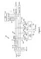
- FIG. 1is a block diagram illustrating a computer network implemented in a customer premises having ISDN-based wiring according to an embodiment of the present invention.
- FIG. 2is a diagram illustrating a delay performed by the low pass filter of FIG. 1 on the ISDN-based signals relative to the network data signals.
- FIG. 3is a diagram illustrating another computer network implemented in a customer premises having a PBX system according to an embodiment of the present invention.
- FIG. 1is a block diagram illustrating an Ethernet (IEEE 802.3) local area network 10 implemented in a home environment using ISDN-based signals according to an embodiment of the present invention.
- the home environmentincludes a network termination basic access (NTBA) device 12 , configured for sending and receiving Integrated Services Digital Network ISDN) signals to and from a public switched telephone network via a two-wire twisted pair.
- the NTBA device 12is configured for outputting ISDN signals onto a four-wire S 0 bus 14 , having two wires for a send path 16 and two wires for a receive path 18 .
- the S 0 bus fourteenmay have multiple connections, or “taps” 20 connected in parallel off the S 0 bus 14 .
- the S 0 busmay be internal to a PBX system; as such, the NTBA 12 serves as a connector for the S 0 bus 14 to the two-wire twisted pair from the public switched telephone network.
- the NTBA 12maps the ISDN signals into a two-wire send path 16 , and a two-wire receive path 18 .
- the receive path 18reflects the ISDN signal transmitted on the send path 16 , with a 2-bit spacing relative to the ISDN clock frequency of about 200 kHz (e.g., 192 kHz).
- home PNAdue to the high level of ISDN noise in the frequency used for home networking, referred to as home PNA by the Home Phone Network Alliance, transmissions of home PNA data on the ISDN S 0 bus 14 is normally not possible.
- a low pass filter 30is installed in the send path 16 of the NTBA 12 .
- the low pass filter 30is illustrated as external to the NTBA 12 , although the low pass filter 30 may also be integrated internally within the NTBA 12 ; in either case, the low pass filter 30 will be coupled to the output terminal of the NTBA device 12 , either internally or externally.
- the low pass filter 30includes an inductor 32 (e.g., 2 ⁇ 4.7 millihenries) and a capacitor 34 (e.g., 1 nanofarad) that attenuates the high frequency noise caused by the harmonics of the 192 kHz ISDN signal.
- the send path 16 and receive path 18are free of high frequency harmonics that may affect the home network signals between end stations 22 a and 22 b .
- the inductor 32implemented for example as a common mode choke, isolates the capacitive influence of NTBA 12 from the two-wire send path 16 , enabling the high frequency home network signals to be transmitted without capacitive loading by the NTBA 12 .
- the disclosed network 10also includes ISDN terminal filters 62 configured for isolating each of the connected ISDN terminal devices 60 from the two-wire send path 16 .
- Each ISDN terminal filter 62is preferably implemented as a common mode choke (e.g., 2 ⁇ 4.7 millihenries) which is connected between the corresponding ISDN terminal device 60 and the two wire send path 16 .
- the low pass filter 30 and the ISDN terminal filters 62isolate the respective ISDN devices from the two-wire send path 16 , providing optimal conditions for transmission of the home network signals having a frequency of at least about 7.5 MHz.
- each end station 22is coupled to a pair of commercially-available S 0 transformers 64 , for example from Vogt Electronic AG of Erlau, Germany.
- the 4-wire tap 20 a of end station 22 ais coupled to the ends of the primary windings of transformers 64 a and 64 b .
- the 4 -wire tap 20 b of end station 22 bis coupled to the end of the primary windings of transformers 64 c and 64 d .
- the secondary windings of transformers 64 a , 64 b , 64 c , and 64 dare not used.
- Each primary windingincludes a middle tap 66 , coupled substantially in the middle (i.e., substantially the center) of the corresponding primary winding.
- the ends of transformers 64 a and 64 bare symmetrically connected to the two wires a 1 , b 1 of the send direction 16 and the two wires a 2 , b 2 of the S 0 bus 14 , respectively.
- the ends of transformers 64 c and 64 dare symmetrically connected to the two wires a 1 , b 1 of the send direction 16 and the two wires a 2 , b 2 of the S 0 bus 14 , respectively.
- Each end station 22outputs the home network signal as a two-wire signal (i.e., a differential signal pair) on two-wire signal lines 68 ; hence, the end station 22 a sends and receives the differential home network signals on signal lines 68 a and 68 b , and the end station 22 b sends and receives the differential home network signals on signal lines 68 c and 68 d.
- a two-wire signali.e., a differential signal pair
- the signal lines 68 a , 68 b , and 68 c , and 68 dare coupled to the middle taps 66 a , 66 b , 66 c , and 66 d , respectively, enabling the two-wire home network signal to be transferred across the four-wire S 0 bus 14 .
- the end station 22outputs a first home network signal to the middle tap 66 a of the primary winding 64 a coupled to the send path 16 , and a second home network signal complementary to the first home network signal (i.e., the corresponding differential signal), to the middle tap 66 b of the primary winding 64 b coupled to the receive path 18 .
- the end station 22 breceives the first home network signal from the send path 16 , and the second home network signal from the receive path 18 , resulting in substantially improved reception of the home network signal by optimizing of the loop resistance of the bus 14 .
- Experimental testing of the disclosed arrangementhas resulted in successful reception of 7.5 MHz home network signals on an S 0 bus 14 where the end stations 22 transmit the home network signals across a distance of about 80 meters.
- Filter 2is a diagram illustrating the delay introduced by the filter 30 . As shown in Filter 2 , the filter 30 introduces a delay 40 . This delay ensures that the zero crossings 46 of the ISDN signal 42 do not offset the network data signals 40 on the receive path 18 .
- FIG. 3is a diagram illustrating an alternative implementation of the local area network 10 of FIG. 1 according to another embodiment of the present invention.
- the network 200includes a private branch exchange (PBX) 210 .
- the PBX 210includes an internal connector 212 for an internal S 0 bus 214 having a send path 216 and a receive path 218 .
- the internal connector 212has circuitry that is configured for connecting the internal S 0 bus 214 to the S 0 bus 14 (also referred to as the external S 0 bus) for communication with the public switched telephone network.
- the PBX 210will typically have four to eight analog (tip-and-ring) connectors (not shown), one external connector for connection to the external S 0 bus, and up to eight digital connections off the S 0 bus 214 .
- the local area network 200also includes the same filters 30 and 62 described above with respect to FIG. 1, and also includes taps 220 connected in parallel off the internal S 0 bus 214 for connection to an ISDN terminal device 60 , and home network end stations 22 a and 22 b coupled to the internal S 0 bus 214 .
- the features of providing filters 30 and 62 to isolate capacitive influences of the connector 212 and ISDN terminal devices 60may also be applied to the internal S 0 bus 214 of the PBX system 210 .
- the filter 30may be integrated within the PBX system 210 .
Landscapes
- Engineering & Computer Science (AREA)
- Computer Networks & Wireless Communication (AREA)
- Signal Processing (AREA)
- Power Engineering (AREA)
- Telephonic Communication Services (AREA)
- Small-Scale Networks (AREA)
- Data Exchanges In Wide-Area Networks (AREA)
Abstract
Description
Claims (11)
Priority Applications (10)
| Application Number | Priority Date | Filing Date | Title |
|---|---|---|---|
| US09/495,123US6522728B1 (en) | 1999-11-03 | 2000-02-01 | Apparatus and method of implementing a universal home network on a customer premises ISDN bus |
| JP2001535306AJP2003513583A (en) | 1999-11-03 | 2000-09-05 | Apparatus and method for implementing a universal home network on an ISDN bus at a customer premises |
| KR1020027005780AKR100683278B1 (en) | 1999-11-03 | 2000-09-05 | Apparatus and method for implementing a universal home network on an ISP bus in a customer building |
| AU73510/00AAU763432B2 (en) | 1999-11-03 | 2000-09-05 | Apparatus and method of implementing a universal home network on a customer premises ISDN bus |
| EP00961571AEP1228575B1 (en) | 1999-11-03 | 2000-09-05 | Apparatus and method of implementing a universal home network on a customer premises isdn bus |
| PCT/US2000/024395WO2001033724A2 (en) | 1999-11-03 | 2000-09-05 | Apparatus and method of implementing a universal home network on a customer premises isdn bus |
| AT00961571TATE254361T1 (en) | 1999-11-03 | 2000-09-05 | APPARATUS AND METHOD FOR INTRODUCING A UNIVERSAL HOME NETWORK ON A SUBSCRIBE ISDN BUS |
| DE60006572TDE60006572T2 (en) | 1999-11-03 | 2000-09-05 | DEVICE AND METHOD FOR IMPLEMENTING A UNIVERSAL HOUSE NETWORK ON A SUBSCRIBER ISDN BUS |
| CNB008153175ACN1144385C (en) | 1999-11-03 | 2000-09-05 | Device and method for realizing universal home network on user building ISDN bus |
| TW089119303ATWI231118B (en) | 1999-11-03 | 2000-09-20 | Apparatus and method of implementing a universal home network on a customer premises ISDN bus |
Applications Claiming Priority (2)
| Application Number | Priority Date | Filing Date | Title |
|---|---|---|---|
| US16323999P | 1999-11-03 | 1999-11-03 | |
| US09/495,123US6522728B1 (en) | 1999-11-03 | 2000-02-01 | Apparatus and method of implementing a universal home network on a customer premises ISDN bus |
Publications (1)
| Publication Number | Publication Date |
|---|---|
| US6522728B1true US6522728B1 (en) | 2003-02-18 |
Family
ID=26859468
Family Applications (1)
| Application Number | Title | Priority Date | Filing Date |
|---|---|---|---|
| US09/495,123Expired - Fee RelatedUS6522728B1 (en) | 1999-11-03 | 2000-02-01 | Apparatus and method of implementing a universal home network on a customer premises ISDN bus |
Country Status (10)
| Country | Link |
|---|---|
| US (1) | US6522728B1 (en) |
| EP (1) | EP1228575B1 (en) |
| JP (1) | JP2003513583A (en) |
| KR (1) | KR100683278B1 (en) |
| CN (1) | CN1144385C (en) |
| AT (1) | ATE254361T1 (en) |
| AU (1) | AU763432B2 (en) |
| DE (1) | DE60006572T2 (en) |
| TW (1) | TWI231118B (en) |
| WO (1) | WO2001033724A2 (en) |
Cited By (22)
| Publication number | Priority date | Publication date | Assignee | Title |
|---|---|---|---|---|
| US20040125819A1 (en)* | 2001-07-05 | 2004-07-01 | Yehuda Binder | Telephone outlet with packet telephony adapter, and a network using same |
| US20040196835A1 (en)* | 2000-03-20 | 2004-10-07 | Serconet Ltd. | Telephone outlet for implementing a local area network over telephone lines and a local area network using such outlets |
| US6836546B1 (en)* | 1999-11-03 | 2004-12-28 | Advanced Micro Devices, Inc. | Apparatus and method of coupling home network signals between an analog phone line and a digital bus |
| US20050010954A1 (en)* | 2003-07-09 | 2005-01-13 | Serconet Ltd. | Modular outlet |
| US20050008033A1 (en)* | 2000-04-18 | 2005-01-13 | Serconet Ltd. | Telephone communication system over a single telephone line |
| US20050047431A1 (en)* | 2001-10-11 | 2005-03-03 | Serconet Ltd. | Outlet with analog signal adapter, a method for use thereof and a network using said outlet |
| US20050249245A1 (en)* | 2004-05-06 | 2005-11-10 | Serconet Ltd. | System and method for carrying a wireless based signal over wiring |
| US20050277328A1 (en)* | 2000-04-19 | 2005-12-15 | Serconet Ltd | Network combining wired and non-wired segments |
| US20060072741A1 (en)* | 2003-01-30 | 2006-04-06 | Serconet Ltd | Method and system for providing DC power on local telephone lines |
| US20070086444A1 (en)* | 2003-03-13 | 2007-04-19 | Serconet Ltd. | Telephone system having multiple distinct sources and accessories therefor |
| US20070173202A1 (en)* | 2006-01-11 | 2007-07-26 | Serconet Ltd. | Apparatus and method for frequency shifting of a wireless signal and systems using frequency shifting |
| US20080226060A1 (en)* | 2004-02-16 | 2008-09-18 | Serconet Ltd. | Outlet add-on module |
| US20080292073A1 (en)* | 1999-07-20 | 2008-11-27 | Serconet, Ltd | Network for telephony and data communication |
| US7873058B2 (en) | 2004-11-08 | 2011-01-18 | Mosaid Technologies Incorporated | Outlet with analog signal adapter, a method for use thereof and a network using said outlet |
| US8175649B2 (en) | 2008-06-20 | 2012-05-08 | Corning Mobileaccess Ltd | Method and system for real time control of an active antenna over a distributed antenna system |
| US8270430B2 (en) | 1998-07-28 | 2012-09-18 | Mosaid Technologies Incorporated | Local area network of serial intelligent cells |
| US8594133B2 (en) | 2007-10-22 | 2013-11-26 | Corning Mobileaccess Ltd. | Communication system using low bandwidth wires |
| US8897215B2 (en) | 2009-02-08 | 2014-11-25 | Corning Optical Communications Wireless Ltd | Communication system using cables carrying ethernet signals |
| US9184960B1 (en) | 2014-09-25 | 2015-11-10 | Corning Optical Communications Wireless Ltd | Frequency shifting a communications signal(s) in a multi-frequency distributed antenna system (DAS) to avoid or reduce frequency interference |
| US9338823B2 (en) | 2012-03-23 | 2016-05-10 | Corning Optical Communications Wireless Ltd | Radio-frequency integrated circuit (RFIC) chip(s) for providing distributed antenna system functionalities, and related components, systems, and methods |
| US10986164B2 (en) | 2004-01-13 | 2021-04-20 | May Patents Ltd. | Information device |
| CN115776421A (en)* | 2022-11-02 | 2023-03-10 | 西安现代控制技术研究所 | Electromagnetic isolation circuit and method of high-speed network bus |
Citations (3)
| Publication number | Priority date | Publication date | Assignee | Title |
|---|---|---|---|---|
| EP0746117A2 (en) | 1995-04-07 | 1996-12-04 | Motorola, Inc. | Transmitter/receiver interface apparatus and method for a bi-directional transmission path |
| US6188750B1 (en)* | 1998-11-19 | 2001-02-13 | Excelsus Technologies, Inc. | Impedance blocking filter circuit |
| US6430199B1 (en)* | 1998-03-27 | 2002-08-06 | Telcordia Technologies, Inc. | Method and system for distributing telephone and broadband services over the copper pairs within a service location |
Family Cites Families (3)
| Publication number | Priority date | Publication date | Assignee | Title |
|---|---|---|---|---|
| JPS56161750A (en)* | 1980-05-16 | 1981-12-12 | Iwatsu Electric Co Ltd | Synchronizing system in telephone set |
| JP3225637B2 (en)* | 1992-11-12 | 2001-11-05 | 株式会社村田製作所 | Chip type choke coil |
| KR20010001792A (en)* | 1999-06-08 | 2001-01-05 | 이영준 | Digital audio file download system |
- 2000
- 2000-02-01USUS09/495,123patent/US6522728B1/ennot_activeExpired - Fee Related
- 2000-09-05JPJP2001535306Apatent/JP2003513583A/enactivePending
- 2000-09-05EPEP00961571Apatent/EP1228575B1/ennot_activeExpired - Lifetime
- 2000-09-05DEDE60006572Tpatent/DE60006572T2/ennot_activeExpired - Lifetime
- 2000-09-05CNCNB008153175Apatent/CN1144385C/ennot_activeExpired - Fee Related
- 2000-09-05ATAT00961571Tpatent/ATE254361T1/ennot_activeIP Right Cessation
- 2000-09-05WOPCT/US2000/024395patent/WO2001033724A2/enactiveIP Right Grant
- 2000-09-05KRKR1020027005780Apatent/KR100683278B1/ennot_activeExpired - Fee Related
- 2000-09-05AUAU73510/00Apatent/AU763432B2/ennot_activeCeased
- 2000-09-20TWTW089119303Apatent/TWI231118B/ennot_activeIP Right Cessation
Patent Citations (3)
| Publication number | Priority date | Publication date | Assignee | Title |
|---|---|---|---|---|
| EP0746117A2 (en) | 1995-04-07 | 1996-12-04 | Motorola, Inc. | Transmitter/receiver interface apparatus and method for a bi-directional transmission path |
| US6430199B1 (en)* | 1998-03-27 | 2002-08-06 | Telcordia Technologies, Inc. | Method and system for distributing telephone and broadband services over the copper pairs within a service location |
| US6188750B1 (en)* | 1998-11-19 | 2001-02-13 | Excelsus Technologies, Inc. | Impedance blocking filter circuit |
Non-Patent Citations (1)
| Title |
|---|
| The Home Phoneline Networking Alliance, "Simple, High-Speed Ethernet Technology For The Home", The White Paper, Jun. 1998 (11 pages). |
Cited By (104)
| Publication number | Priority date | Publication date | Assignee | Title |
|---|---|---|---|---|
| US8867523B2 (en) | 1998-07-28 | 2014-10-21 | Conversant Intellectual Property Management Incorporated | Local area network of serial intelligent cells |
| US8325636B2 (en) | 1998-07-28 | 2012-12-04 | Mosaid Technologies Incorporated | Local area network of serial intelligent cells |
| US8908673B2 (en) | 1998-07-28 | 2014-12-09 | Conversant Intellectual Property Management Incorporated | Local area network of serial intelligent cells |
| US8885660B2 (en) | 1998-07-28 | 2014-11-11 | Conversant Intellectual Property Management Incorporated | Local area network of serial intelligent cells |
| US8885659B2 (en) | 1998-07-28 | 2014-11-11 | Conversant Intellectual Property Management Incorporated | Local area network of serial intelligent cells |
| US8270430B2 (en) | 1998-07-28 | 2012-09-18 | Mosaid Technologies Incorporated | Local area network of serial intelligent cells |
| US8929523B2 (en) | 1999-07-20 | 2015-01-06 | Conversant Intellectual Property Management Inc. | Network for telephony and data communication |
| US20080292073A1 (en)* | 1999-07-20 | 2008-11-27 | Serconet, Ltd | Network for telephony and data communication |
| US7483524B2 (en) | 1999-07-20 | 2009-01-27 | Serconet, Ltd | Network for telephony and data communication |
| US7522713B2 (en) | 1999-07-20 | 2009-04-21 | Serconet, Ltd. | Network for telephony and data communication |
| US7492875B2 (en) | 1999-07-20 | 2009-02-17 | Serconet, Ltd. | Network for telephony and data communication |
| US8351582B2 (en) | 1999-07-20 | 2013-01-08 | Mosaid Technologies Incorporated | Network for telephony and data communication |
| US6836546B1 (en)* | 1999-11-03 | 2004-12-28 | Advanced Micro Devices, Inc. | Apparatus and method of coupling home network signals between an analog phone line and a digital bus |
| US8855277B2 (en) | 2000-03-20 | 2014-10-07 | Conversant Intellectual Property Managment Incorporated | Telephone outlet for implementing a local area network over telephone lines and a local area network using such outlets |
| US20060133588A1 (en)* | 2000-03-20 | 2006-06-22 | Serconet Ltd. | Telephone outlet for implementing a local area network over telephone lines and a local area network using such outlets |
| US7522714B2 (en)* | 2000-03-20 | 2009-04-21 | Serconet Ltd. | Telephone outlet for implementing a local area network over telephone lines and a local area network using such outlets |
| US7123701B2 (en)* | 2000-03-20 | 2006-10-17 | Serconet, Ltd. | Telephone outlet for implementing a local area network over telephone lines and a local area network using such outlets |
| US8363797B2 (en) | 2000-03-20 | 2013-01-29 | Mosaid Technologies Incorporated | Telephone outlet for implementing a local area network over telephone lines and a local area network using such outlets |
| US20040196835A1 (en)* | 2000-03-20 | 2004-10-07 | Serconet Ltd. | Telephone outlet for implementing a local area network over telephone lines and a local area network using such outlets |
| US7715534B2 (en) | 2000-03-20 | 2010-05-11 | Mosaid Technologies Incorporated | Telephone outlet for implementing a local area network over telephone lines and a local area network using such outlets |
| US20050117603A1 (en)* | 2000-04-18 | 2005-06-02 | Serconet, Ltd. | Telephone communication system over a single telephone line |
| US8223800B2 (en) | 2000-04-18 | 2012-07-17 | Mosaid Technologies Incorporated | Telephone communication system over a single telephone line |
| US8000349B2 (en) | 2000-04-18 | 2011-08-16 | Mosaid Technologies Incorporated | Telephone communication system over a single telephone line |
| US7197028B2 (en) | 2000-04-18 | 2007-03-27 | Serconet Ltd. | Telephone communication system over a single telephone line |
| US7593394B2 (en) | 2000-04-18 | 2009-09-22 | Mosaid Technologies Incorporated | Telephone communication system over a single telephone line |
| US20080043646A1 (en)* | 2000-04-18 | 2008-02-21 | Serconet Ltd. | Telephone communication system over a single telephone line |
| US20060182095A1 (en)* | 2000-04-18 | 2006-08-17 | Serconet Ltd. | Telephone communication system over a single telephone line |
| US7397791B2 (en) | 2000-04-18 | 2008-07-08 | Serconet, Ltd. | Telephone communication system over a single telephone line |
| US20060182094A1 (en)* | 2000-04-18 | 2006-08-17 | Serconet Ltd. | Telephone communication system over a single telephone line |
| US8559422B2 (en) | 2000-04-18 | 2013-10-15 | Mosaid Technologies Incorporated | Telephone communication system over a single telephone line |
| US7466722B2 (en) | 2000-04-18 | 2008-12-16 | Serconet Ltd | Telephone communication system over a single telephone line |
| US20050008033A1 (en)* | 2000-04-18 | 2005-01-13 | Serconet Ltd. | Telephone communication system over a single telephone line |
| US8848725B2 (en) | 2000-04-19 | 2014-09-30 | Conversant Intellectual Property Management Incorporated | Network combining wired and non-wired segments |
| US7633966B2 (en) | 2000-04-19 | 2009-12-15 | Mosaid Technologies Incorporated | Network combining wired and non-wired segments |
| US20050277328A1 (en)* | 2000-04-19 | 2005-12-15 | Serconet Ltd | Network combining wired and non-wired segments |
| US8982904B2 (en) | 2000-04-19 | 2015-03-17 | Conversant Intellectual Property Management Inc. | Network combining wired and non-wired segments |
| US8867506B2 (en) | 2000-04-19 | 2014-10-21 | Conversant Intellectual Property Management Incorporated | Network combining wired and non-wired segments |
| US8873586B2 (en) | 2000-04-19 | 2014-10-28 | Conversant Intellectual Property Management Incorporated | Network combining wired and non-wired segments |
| US8982903B2 (en) | 2000-04-19 | 2015-03-17 | Conversant Intellectual Property Management Inc. | Network combining wired and non-wired segments |
| US8873575B2 (en) | 2000-04-19 | 2014-10-28 | Conversant Intellectual Property Management Incorporated | Network combining wired and non-wired segments |
| US7680255B2 (en) | 2001-07-05 | 2010-03-16 | Mosaid Technologies Incorporated | Telephone outlet with packet telephony adaptor, and a network using same |
| US7542554B2 (en) | 2001-07-05 | 2009-06-02 | Serconet, Ltd | Telephone outlet with packet telephony adapter, and a network using same |
| US8472593B2 (en) | 2001-07-05 | 2013-06-25 | Mosaid Technologies Incorporated | Telephone outlet with packet telephony adaptor, and a network using same |
| US8761186B2 (en) | 2001-07-05 | 2014-06-24 | Conversant Intellectual Property Management Incorporated | Telephone outlet with packet telephony adapter, and a network using same |
| US20040125819A1 (en)* | 2001-07-05 | 2004-07-01 | Yehuda Binder | Telephone outlet with packet telephony adapter, and a network using same |
| US20050063403A1 (en)* | 2001-07-05 | 2005-03-24 | Serconet Ltd. | Telephone outlet with packet telephony adaptor, and a network using same |
| US20050083959A1 (en)* | 2001-07-05 | 2005-04-21 | Serconet, Ltd. | Telephone outlet with packet telephony adapter, and a network using same |
| US7769030B2 (en) | 2001-07-05 | 2010-08-03 | Mosaid Technologies Incorporated | Telephone outlet with packet telephony adapter, and a network using same |
| US20080134263A1 (en)* | 2001-10-11 | 2008-06-05 | Serconet Ltd. | Outlet with analog signal adapter, a method for use thereof and a network using said outlet |
| US7436842B2 (en) | 2001-10-11 | 2008-10-14 | Serconet Ltd. | Outlet with analog signal adapter, a method for use thereof and a network using said outlet |
| US7860084B2 (en) | 2001-10-11 | 2010-12-28 | Mosaid Technologies Incorporated | Outlet with analog signal adapter, a method for use thereof and a network using said outlet |
| US7453895B2 (en) | 2001-10-11 | 2008-11-18 | Serconet Ltd | Outlet with analog signal adapter, a method for use thereof and a network using said outlet |
| US20060098638A1 (en)* | 2001-10-11 | 2006-05-11 | Serconet Ltd. | Outlet with analog signal adapter, a method for use thereof and a network using said outlet |
| US7889720B2 (en) | 2001-10-11 | 2011-02-15 | Mosaid Technologies Incorporated | Outlet with analog signal adapter, a method for use thereof and a network using said outlet |
| US20110096778A1 (en)* | 2001-10-11 | 2011-04-28 | Mosaid Technologies Incorporated | Outlet with analog signal adapter, a method for use thereof and a network using said outlet |
| US20050047431A1 (en)* | 2001-10-11 | 2005-03-03 | Serconet Ltd. | Outlet with analog signal adapter, a method for use thereof and a network using said outlet |
| US7953071B2 (en) | 2001-10-11 | 2011-05-31 | Mosaid Technologies Incorporated | Outlet with analog signal adapter, a method for use thereof and a network using said outlet |
| US8107618B2 (en) | 2003-01-30 | 2012-01-31 | Mosaid Technologies Incorporated | Method and system for providing DC power on local telephone lines |
| US7702095B2 (en) | 2003-01-30 | 2010-04-20 | Mosaid Technologies Incorporated | Method and system for providing DC power on local telephone lines |
| US20070127715A1 (en)* | 2003-01-30 | 2007-06-07 | Serconet Ltd | Method and system for providing DC power on local telephone lines |
| US8787562B2 (en) | 2003-01-30 | 2014-07-22 | Conversant Intellectual Property Management Inc. | Method and system for providing DC power on local telephone lines |
| US20060072741A1 (en)* | 2003-01-30 | 2006-04-06 | Serconet Ltd | Method and system for providing DC power on local telephone lines |
| US20060233354A1 (en)* | 2003-01-30 | 2006-10-19 | Serconet Ltd | Method and system for providing DC power on local telephone Lines |
| US7317793B2 (en) | 2003-01-30 | 2008-01-08 | Serconet Ltd | Method and system for providing DC power on local telephone lines |
| US7738453B2 (en) | 2003-03-13 | 2010-06-15 | Mosaid Technologies Incorporated | Telephone system having multiple sources and accessories therefor |
| US7746905B2 (en) | 2003-03-13 | 2010-06-29 | Mosaid Technologies Incorporated | Private telephone network connected to more than one public network |
| US20070147433A1 (en)* | 2003-03-13 | 2007-06-28 | Serconet Ltd. | Telephone system having multiple distinct sources and accessories therefor |
| US8238328B2 (en) | 2003-03-13 | 2012-08-07 | Mosaid Technologies Incorporated | Telephone system having multiple distinct sources and accessories therefor |
| US20070086444A1 (en)* | 2003-03-13 | 2007-04-19 | Serconet Ltd. | Telephone system having multiple distinct sources and accessories therefor |
| US7656904B2 (en) | 2003-03-13 | 2010-02-02 | Mosaid Technologies Incorporated | Telephone system having multiple distinct sources and accessories therefor |
| US7867035B2 (en) | 2003-07-09 | 2011-01-11 | Mosaid Technologies Incorporated | Modular outlet |
| US20050010954A1 (en)* | 2003-07-09 | 2005-01-13 | Serconet Ltd. | Modular outlet |
| US8092258B2 (en) | 2003-09-07 | 2012-01-10 | Mosaid Technologies Incorporated | Modular outlet |
| US7686653B2 (en) | 2003-09-07 | 2010-03-30 | Mosaid Technologies Incorporated | Modular outlet |
| US8591264B2 (en) | 2003-09-07 | 2013-11-26 | Mosaid Technologies Incorporated | Modular outlet |
| US8360810B2 (en) | 2003-09-07 | 2013-01-29 | Mosaid Technologies Incorporated | Modular outlet |
| US20070041340A1 (en)* | 2003-09-07 | 2007-02-22 | Serconet Ltd. | Modular outlet |
| US8235755B2 (en) | 2003-09-07 | 2012-08-07 | Mosaid Technologies Incorporated | Modular outlet |
| US20110097939A1 (en)* | 2003-09-07 | 2011-04-28 | Mosaid Technologies Incorporated | Modular outlet |
| US11032353B2 (en) | 2004-01-13 | 2021-06-08 | May Patents Ltd. | Information device |
| US10986164B2 (en) | 2004-01-13 | 2021-04-20 | May Patents Ltd. | Information device |
| US11095708B2 (en) | 2004-01-13 | 2021-08-17 | May Patents Ltd. | Information device |
| US10986165B2 (en) | 2004-01-13 | 2021-04-20 | May Patents Ltd. | Information device |
| US20080226060A1 (en)* | 2004-02-16 | 2008-09-18 | Serconet Ltd. | Outlet add-on module |
| US8611528B2 (en) | 2004-02-16 | 2013-12-17 | Mosaid Technologies Incorporated | Outlet add-on module |
| US8325759B2 (en) | 2004-05-06 | 2012-12-04 | Corning Mobileaccess Ltd | System and method for carrying a wireless based signal over wiring |
| US20050249245A1 (en)* | 2004-05-06 | 2005-11-10 | Serconet Ltd. | System and method for carrying a wireless based signal over wiring |
| US7873058B2 (en) | 2004-11-08 | 2011-01-18 | Mosaid Technologies Incorporated | Outlet with analog signal adapter, a method for use thereof and a network using said outlet |
| US7587001B2 (en) | 2006-01-11 | 2009-09-08 | Serconet Ltd. | Apparatus and method for frequency shifting of a wireless signal and systems using frequency shifting |
| US20070173202A1 (en)* | 2006-01-11 | 2007-07-26 | Serconet Ltd. | Apparatus and method for frequency shifting of a wireless signal and systems using frequency shifting |
| US7813451B2 (en) | 2006-01-11 | 2010-10-12 | Mobileaccess Networks Ltd. | Apparatus and method for frequency shifting of a wireless signal and systems using frequency shifting |
| US8184681B2 (en) | 2006-01-11 | 2012-05-22 | Corning Mobileaccess Ltd | Apparatus and method for frequency shifting of a wireless signal and systems using frequency shifting |
| US8594133B2 (en) | 2007-10-22 | 2013-11-26 | Corning Mobileaccess Ltd. | Communication system using low bandwidth wires |
| US9813229B2 (en) | 2007-10-22 | 2017-11-07 | Corning Optical Communications Wireless Ltd | Communication system using low bandwidth wires |
| US9549301B2 (en) | 2007-12-17 | 2017-01-17 | Corning Optical Communications Wireless Ltd | Method and system for real time control of an active antenna over a distributed antenna system |
| US8175649B2 (en) | 2008-06-20 | 2012-05-08 | Corning Mobileaccess Ltd | Method and system for real time control of an active antenna over a distributed antenna system |
| US8897215B2 (en) | 2009-02-08 | 2014-11-25 | Corning Optical Communications Wireless Ltd | Communication system using cables carrying ethernet signals |
| US9338823B2 (en) | 2012-03-23 | 2016-05-10 | Corning Optical Communications Wireless Ltd | Radio-frequency integrated circuit (RFIC) chip(s) for providing distributed antenna system functionalities, and related components, systems, and methods |
| US9948329B2 (en) | 2012-03-23 | 2018-04-17 | Corning Optical Communications Wireless, LTD | Radio-frequency integrated circuit (RFIC) chip(s) for providing distributed antenna system functionalities, and related components, systems, and methods |
| US10141959B2 (en) | 2012-03-23 | 2018-11-27 | Corning Optical Communications Wireless Ltd | Radio-frequency integrated circuit (RFIC) chip(s) for providing distributed antenna system functionalities, and related components, systems, and methods |
| US9515855B2 (en) | 2014-09-25 | 2016-12-06 | Corning Optical Communications Wireless Ltd | Frequency shifting a communications signal(s) in a multi-frequency distributed antenna system (DAS) to avoid or reduce frequency interference |
| US9253003B1 (en) | 2014-09-25 | 2016-02-02 | Corning Optical Communications Wireless Ltd | Frequency shifting a communications signal(S) in a multi-frequency distributed antenna system (DAS) to avoid or reduce frequency interference |
| US9184960B1 (en) | 2014-09-25 | 2015-11-10 | Corning Optical Communications Wireless Ltd | Frequency shifting a communications signal(s) in a multi-frequency distributed antenna system (DAS) to avoid or reduce frequency interference |
| CN115776421A (en)* | 2022-11-02 | 2023-03-10 | 西安现代控制技术研究所 | Electromagnetic isolation circuit and method of high-speed network bus |
Also Published As
| Publication number | Publication date |
|---|---|
| WO2001033724A2 (en) | 2001-05-10 |
| DE60006572T2 (en) | 2004-09-16 |
| KR100683278B1 (en) | 2007-02-15 |
| KR20020052201A (en) | 2002-07-02 |
| ATE254361T1 (en) | 2003-11-15 |
| WO2001033724A3 (en) | 2001-12-06 |
| CN1387701A (en) | 2002-12-25 |
| AU7351000A (en) | 2001-05-14 |
| TWI231118B (en) | 2005-04-11 |
| CN1144385C (en) | 2004-03-31 |
| EP1228575B1 (en) | 2003-11-12 |
| DE60006572D1 (en) | 2003-12-18 |
| EP1228575A2 (en) | 2002-08-07 |
| AU763432B2 (en) | 2003-07-24 |
| JP2003513583A (en) | 2003-04-08 |
Similar Documents
| Publication | Publication Date | Title |
|---|---|---|
| US6836546B1 (en) | Apparatus and method of coupling home network signals between an analog phone line and a digital bus | |
| US6522728B1 (en) | Apparatus and method of implementing a universal home network on a customer premises ISDN bus | |
| EP1169821B1 (en) | Apparatus and method for coupling analog subscriber lines in a home network | |
| US6624745B1 (en) | Low pass filter for a universal home network on a customer premises european installation bus | |
| US6584079B1 (en) | Apparatus and method of implementing a home network by filtering ISDN-based signals within the customer premises | |
| US6377665B1 (en) | Apparatus and method of implementing a universal home network on a customer premises UPN telephone lines | |
| US6393109B1 (en) | Apparatus and method of coupling home network signals between an analog phone line and a digital UPN line |
Legal Events
| Date | Code | Title | Description |
|---|---|---|---|
| AS | Assignment | Owner name:ADVANCED MICRO DEVICES, INC., CALIFORNIA Free format text:ASSIGNMENT OF ASSIGNORS INTEREST;ASSIGNOR:WILLER, BERND;REEL/FRAME:010540/0590 Effective date:20000125 | |
| FEPP | Fee payment procedure | Free format text:PAYOR NUMBER ASSIGNED (ORIGINAL EVENT CODE: ASPN); ENTITY STATUS OF PATENT OWNER: LARGE ENTITY | |
| FPAY | Fee payment | Year of fee payment:4 | |
| AS | Assignment | Owner name:GLOBALFOUNDRIES INC., CAYMAN ISLANDS Free format text:AFFIRMATION OF PATENT ASSIGNMENT;ASSIGNOR:ADVANCED MICRO DEVICES, INC.;REEL/FRAME:023119/0083 Effective date:20090630 | |
| AS | Assignment | Owner name:VERTICAL CIRCULTS, INC., CALIFORNIA Free format text:RELEASE;ASSIGNOR:SILICON VALLEY BANK;REEL/FRAME:023148/0183 Effective date:20090824 | |
| FPAY | Fee payment | Year of fee payment:8 | |
| CC | Certificate of correction | ||
| REMI | Maintenance fee reminder mailed | ||
| LAPS | Lapse for failure to pay maintenance fees | ||
| STCH | Information on status: patent discontinuation | Free format text:PATENT EXPIRED DUE TO NONPAYMENT OF MAINTENANCE FEES UNDER 37 CFR 1.362 | |
| FP | Lapsed due to failure to pay maintenance fee | Effective date:20150218 | |
| AS | Assignment | Owner name:GLOBALFOUNDRIES U.S. INC., NEW YORK Free format text:RELEASE BY SECURED PARTY;ASSIGNOR:WILMINGTON TRUST, NATIONAL ASSOCIATION;REEL/FRAME:056987/0001 Effective date:20201117 |