US6522264B1 - Airport parking communication system - Google Patents
Airport parking communication systemDownload PDFInfo
- Publication number
- US6522264B1 US6522264B1US09/653,515US65351500AUS6522264B1US 6522264 B1US6522264 B1US 6522264B1US 65351500 AUS65351500 AUS 65351500AUS 6522264 B1US6522264 B1US 6522264B1
- Authority
- US
- United States
- Prior art keywords
- customer
- vehicle
- location
- radio frequency
- data
- Prior art date
- Legal status (The legal status is an assumption and is not a legal conclusion. Google has not performed a legal analysis and makes no representation as to the accuracy of the status listed.)
- Expired - Fee Related
Links
Images


Classifications
- G—PHYSICS
- G08—SIGNALLING
- G08G—TRAFFIC CONTROL SYSTEMS
- G08G1/00—Traffic control systems for road vehicles
- G08G1/20—Monitoring the location of vehicles belonging to a group, e.g. fleet of vehicles, countable or determined number of vehicles
- G08G1/202—Dispatching vehicles on the basis of a location, e.g. taxi dispatching
- G—PHYSICS
- G07—CHECKING-DEVICES
- G07B—TICKET-ISSUING APPARATUS; FARE-REGISTERING APPARATUS; FRANKING APPARATUS
- G07B15/00—Arrangements or apparatus for collecting fares, tolls or entrance fees at one or more control points
- G07B15/02—Arrangements or apparatus for collecting fares, tolls or entrance fees at one or more control points taking into account a variable factor such as distance or time, e.g. for passenger transport, parking systems or car rental systems
- G—PHYSICS
- G08—SIGNALLING
- G08G—TRAFFIC CONTROL SYSTEMS
- G08G1/00—Traffic control systems for road vehicles
- G08G1/01—Detecting movement of traffic to be counted or controlled
- G08G1/017—Detecting movement of traffic to be counted or controlled identifying vehicles
- G—PHYSICS
- G08—SIGNALLING
- G08G—TRAFFIC CONTROL SYSTEMS
- G08G1/00—Traffic control systems for road vehicles
- G08G1/123—Traffic control systems for road vehicles indicating the position of vehicles, e.g. scheduled vehicles; Managing passenger vehicles circulating according to a fixed timetable, e.g. buses, trains, trams
Definitions
- This inventiongenerally relates to the field of transportation systems and, more specifically, relates to an airport parking communication system.
- Many modem airportshave perimeter parking lots where passengers park their vehicles while they travel to a remote destination and return. Many such parking lots are operated by commercial organizations, such as car rental and travel companies.
- the parking lotsusually provide courtesy vans, or buses, for carrying customers from the perimeter parking lot to the airport, and from the airport to the perimeter parking lot. Transporting customers from the perimeter parking lot to the airport is relatively easy, because customers will congregate at the parking lot reception area located at the perimeter parking lot after parking their cars. However, knowing when to send a bus to pick a customer up at the airport and deliver them to the perimeter parking lot is considerably more difficult.
- Previous systems and methods for determining when to pick a customer up at the airporthave required customers to call the parking lot reception area to request a courtesy pick-up after they have arrived and collected their luggage.
- these systemsrequire customers to transport their luggage to a telephone, make a telephone call, and wait for the courtesy bus to arrive. This process can be extremely burdensome and inconvenient for a customer. Accordingly, in light of these problems, there is a need for an airport communication system that can reduce the complexity of current parking lot notification systems and increase customer convenience.
- the present inventionsolves the above-described problems by providing a method and system for providing customer arrival information to a parking lot attendant.
- a radio frequency identification (“RFID”) tagwhen a customer arrives at a parking lot, the customer is provided a radio frequency identification (“RFID”) tag.
- the RFID tagcontains information uniquely identifying the customer. For instance, the RFID tag may be encoded with a unique identification number or the customer's name and vehicle slot number may be electronically written onto the RFID tag. This information is then stored in a parking system database. This occurs before the customer enters the courtesy bus for the terminal of the airport.
- the customerWhen the customer returns to the airport and gathers their luggage, the customer moves to an island that includes readers that read the information stored in the RFID tag carried by the customer.
- the informationis transmitted to the parking lot, where an attendant dispatches a courtesy bus, or communicates with one already en route, and delivers the customer's car to a delivery area.
- the customerneed not take any other action than carrying the RFID tag to the island to be retrieved by a courtesy bus and have their car waiting for them at the parking lot.
- An RFID interrogatoris also provided in an embodiment of the present invention for decoding the information encoded on the RFID tag.
- the RFID interrogatoris connected to one or more antennas mounted in an area where customers returning to the airport will congregate.
- the RFID interrogatoris also connected to a computer for communicating with a base computer located at the remote parking lot.
- the RFID interrogatordecodes the information encoded on the RFID tag and transmits this information to the base computer.
- the base computeruses this information to dispatch a bus to retrieve the customer and return them to the parking lot where their vehicle is parked.
- the base computermay also locate the appropriate vehicle slot number and display this information to an attendant. The attendant may then use this information to retrieve the customer's car.
- the base computertransmits information regarding the arrival time of the next courtesy bus to the interrogator computer, which may then be displayed for the benefit of the customer.
- an RFID interrogatoris also placed proximate to the entrance of the parking lot.
- a customeris issued a RFID tag on their first visit to the parking lot that contains information uniquely identifying the RFID tag.
- the RFID interrogatorreads the information from the RFID tag as the customer enters the parking lot.
- the information contained in the RFID tagis then used to reference an entry in the parking system database relating to the customer.
- the database entryis updated to reflect that the customer has parked their car in that particular parking lot.
- the RFID interrogator located at the airportreads the information from the customer's RFID tag and transmits this information to the parking lot base computer.
- a displaymay be provided at the entrance to the parking lot to inform the customer, that their RFID tag has been correctly interrogated.
- the base computerthen uses this information to dispatch a bus to retrieve the customer and return them to the parking lot where their vehicle is parked.
- FIG. 1is a block diagram illustrating an actual operating environment for aspects of the present invention.
- FIG. 2is a block diagram showing a RFID tag and an RFID encoder utilized in an embodiment of the present invention.
- FIG. 3is a block diagram showing further aspects of an actual operating environment for the present invention.
- FIG. 4is a block diagram showing an illustrative installation of an interrogator, a computer, antennas, and a display in the illustrative operating environment.
- FIG. 5is a block diagram illustrating the architecture of an RFID interrogator and computer utilized in an actual embodiment of the present invention.
- FIG. 7is a flow diagram illustrating a routine for encoding a RFID tag according to an actual embodiment of the present invention.
- FIGS. 8A and 8Bare state diagrams illustrating the operation of a RFID interrogator and interrogator computer according to an actual embodiment of the present invention.
- FIGS. 9A-9Care state diagrams illustrating the operation of a base computer according to an embodiment of the present invention.
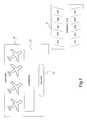
- FIG. 1shows an illustrative operating environment for aspects of the invention.
- the customeris issued an RFID tag.
- the RFID tagcontains information uniquely identifying the RFID tag.
- the tagmay be encoded with a unique identification number 1 or may be manufactured containing a unique identification number 1 .
- the customer's name and vehicle slot number 12 A- 12 Nmay also be electronically written onto the tag.
- This information uniquely identifying the RFID tagis then stored in a parking system database. This occurs before the customer enters a courtesy bus for the terminal 13 of the airport 15 .
- An RFID encoder for encoding a RFID tagis described below with respect to FIG. 2 .
- the customerAfter the customer returns to the airport 15 and gathers his bag at the terminal 13 , the customer proceeds to an island 17 that includes RFID interrogators that read the information stored in the RFID tag carried by the customer.
- An illustrative island 17 and RFID interrogatorare described below with respect to FIGS. 3 and 4, respectively.
- the read informationis transmitted to a base computer located at the parking lot 11 .
- the informationis used to dispatch a bus to pick up the customer at the island 17 .
- the informationmay also displayed to an attendant so that the attendant may retrieve the customer's car from the appropriate vehicle slot number 12 A- 12 N, and make the vehicle ready for the customer upon arrival.
- the base computermay also transmit information regarding the arrival time for the next courtesy bus to the island, where it may be displayed for the customer.
- An illustrative base computerwill be described below with reference to FIG. 6 .
- an illustrative RFID encoder 14When a customer arrives at the parking lot 11 , the customer provides their name and the vehicle slot number 12 A- 12 N in which they parked their vehicle. This information is entered into the RFID encoder 14 using a keypad 2 .
- the cpu/memory unit 3 of the RFID encoderstores this information in a parking system database 4 for later retrieval. The arrival time of the customer at the parking lot may also be stored in the parking system database 4 for use in determining the parking fees owed by the customer upon their return.
- the cpu/memory unit 3also controls the operation of a card encoder 5 for encoding the customer name 8 and vehicle slot number 9 onto an RFID card 7 . Encoded RFID tags can be remotely interrogated (decoded) by RFID decoders, described below. The card is then issued to the customer and the customer takes the card with them.
- the RFID tag 7may be encoded with a unique identification number 1 .
- the unique identification number 1is used to identify the customer.
- the RFID tag 7may come from the manufacturer with a pre-encoded unique identification number 1 , or the unique identification number 1 may be written to the RFID tag 7 by the RFID encoder 14 .
- the island 17includes a bank of phones 19 , columns 21 A and 21 B for supporting an overhead protective roof, and one or more benches 23 A and 23 B.
- an interrogator housing, a computer housing, and one or more antennasmay be mounted on one of the columns 21 B for decoding information from RFID tags located proximate to the column.
- a displaymay be mounted above the bank of phones 19 for displaying information to the customer regarding the arrival time for the next bus.
- the bank of phones 19includes one or more telephones 20 A- 20 N connected to the public switched telephone system by way of phone lines 22 A- 22 N.
- a display 25is mounted atop the bank of phones 19 .
- the displayis connected to the computer housing 29 and displays information regarding the arrival time of the next courtesy bus, advertising, or other information.
- the antennas 31 A- 31 Nemit a radio frequency signal 24 that, when reflected back to the antennas 31 A- 31 N, allow the RFID interrogator to decode the information contained in an RFID tag located within the signal range of the antennas 31 A- 31 N.
- Also mounted on the column 21 Bis an interrogator housing 27 and a computer housing 29 .
- the antennas 31 A- 31 Nare connected to an RFID interrogator 37 via transmission lines 33 .
- the RFID interrogator 37is mounted within interrogator housing 27 , which is attached to one of the columns 21 B.
- the RFID interrogator 37is connected to a power source 41 .
- the RFID interrogator 37is also connected to a computer 39 mounted in the computer housing 29 .
- the computer 39is also connected to a power source 45 , which is also located in the computer housing 29 .
- the computer 39is also connected to the display 25 and to a base computer located at the parking lot via the phone line 22 .
- the RFID interrogator 37continuously interrogates the region surrounding the column 21 B.
- the information contained in the RFID tagis read and decoded by the RFID interrogator 37 .
- the RFID interrogator 37supplies the read information to the computer 39 , which transmits the information to the base computer via the phone line 22 .
- the computer 39also causes the display 25 to display information to waiting customers regarding the waiting time for the next courtesy bus. Arrival information is supplied to the computer 39 by the base computer located at the parking lot.
- RFID tag datamay be broadcast to each of the base computers when the RFID tag is read and decoded by the RFID interrogator 37 .
- Each base computermay then determine whether the information encoded on the RFID tag corresponds to an entry in their particular parking lot database. If it does not, no action will be taken. If a corresponding entry is found, the courtesy bus will be dispatched as described above.
- the RFID tagmay be encoded with information identifying the particular parking lot at which a customer parked their vehicle. When the RFID tag is read, the decoded information will only be transmitted to the base computer located at the particular parking lot identified in the encoded data.
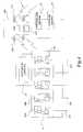
- the base computer 51is located at the parking lot and comprises a cpu/memory unit 53 for controlling the operation of the base computer 51 , a display adapter 54 A for providing video signals to the display 57 , and a modem 52 for communicating with the computer 39 via the phone line 22 .
- the base computer 51may also maintain a parking system database 4 on a non-volatile storage medium, for storing the customer name 8 , the vehicle slot number 9 , and the arrival time 50 for each customer.
- the base computer 51may also comprise other conventional computing components not shown in FIG. 6 .
- the base computer 51receives RFIG tag data 55 from the computer 39 .
- the base computer 51retrieves the relevant data from the parking system database 4 .
- the base computer 51displays the vehicle slot number 9 on the display 57 so that an attendant may retrieve the customer's vehicle from the appropriate slot and make the vehicle ready for the customer's arrival.
- the base computer 51may also provide an alert to a dispatcher so that a courtesy bus may be sent to retrieve the customer. Alternatively, a communication may be made to a courtesy bus already en route to notify the bus that the customer should be picked up.
- the base computer 51transmits bus arrival information 56 to the computer 39 . As described above, this bus arrival information is displayed for the benefit of the customer by the computer 39 .
- the base computer 51also includes an I/O interface 60 for communicating with an attached RFID interrogator 37 .
- the RFID interrogator 37is connected to antennas 31 A- 31 B which are mounted proximate to the entrance to the parking lot.
- the RFID interrogator 37reads the information from the customer's RFID tag as they enter the parking lot.
- the parking system database 17is then updated to indicate that the customer has arrived.
- the base computer 51may also include a display adapter 54 B for controlling display 62 .
- the display 62may also be mounted proximate to the entrance to the parking lot and utilized to provide an indication to the customer when they arrive that their RFID tag has been correctly read.
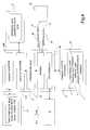
- Routine 700begins at block 702 , where the customer name and vehicle slot number are received. This information may be provided by an attendant or by the customer. Routine 700 then continues from block 702 to block 704 , where the customer's name and vehicle slot number are encoded on an RFID tag. Additional information may also be encoded on the RFID tag, such as the date and time of arrival of the customer, automobile make and model, and other such information. Alternatively, a unique identification number may be written to the RFID tag or, if the RFID tag was manufactured with a unique identification number, this number may be read from the RFID tag and stored in the parking system database. From block 704 , the Routine 700 continues to block 706 .
- the information uniquely identifying the customerare stored in the parking system database.
- the customer name, vehicle slot number, and arrival timeare stored in the parking system database.
- the unique identification numbermay be stored in the parking system database as described above.
- additional informationmay also be stored in the parking system database as known to those skilled in the art, such as the vehicle make, model, and color, license tag number, etc.
- Routine 700then continues from block 706 to block 708 , where the RFID tag is provided to the customer. The customer is instructed to keep the RFID tag in a safe place and to have it available when they return to the airport. According to an embodiment of the present invention, the customer is issued the RFID tag only once. The Routine 700 then returns to block 702 , where the next RFID tag is encoded.
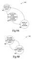
- State diagram 800begins at state 802 , where the RFID interrogator continually interrogates RFID tags. If an RFID tag is found, the state diagram 800 moves from state 802 to state 804 , where the data encoded in the RFID tag is retrieved and decoded. If the data is invalid, the state diagram returns to state 802 from state 804 , and continues to decode RFID tags. If the data is valid, the state diagram moves from state 804 to state 806 , where the RFID tag data is transmitted to the base computer located at the parking lot.
- State diagram 850begins at state 808 , where bus arrival information is received at the interrogator computer from the base computer. When such information is received, the state changes from state 808 to 810 . At state 810 , the computer displays the bus arrival information on the display. As mentioned above, other types of information such as advertising may also be displayed by the computer.
- State diagram 900begins at state 902 , where RFID tag data is received at the base computer from the RFID interrogator.
- the state diagram 900then moves to state 904 , where data corresponding to the received RFID tag data is retrieved from the parking system database.
- the state diagramthen moves to state 906 , where the vehicle slot number is displayed. This information may be utilized by a parking attendant to retrieve the customers car. Additionally, a dispatcher may be notified by the base computer to dispatch a bus to retrieve the waiting customer.
- the state diagramthen returns to state 902 , where additional RFID tag data is received.
- the state diagram 950begins at state 908 , where updated bus arrival data is received at the base computer. This data may be provided in an automated fashion or may be entered by hand into the base computer upon dispatch of a bus. The state diagram 950 then moves to state 910 , where the bus arrival data is transmitted to the computer located at the airport. This information is then displayed by the computer for the customer's benefit. The routine 950 then returns to state 908 , where further bus arrival data is received.
- the base computeris further equipped with a display mounted proximate to the entrance of the parking lot and an RFID interrogator also placed proximate to the entrance to the parking lot.
- State diagram 975 shown in FIG. 9Cillustrates the further operation of the base computer in such an embodiment.
- State diagram 975begins at state 912 , where the area surrounding the entrance to the parking lot is interrogated for RFID tags. If an RFID tag is located, the state diagram 975 changes to state 914 , where a determination is made as to whether the data decoded from the RFID tag is valid. If the data is not valid, the state returns to state 912 . If the data is valid, the state continues to state 914 .
- the parking system databaseis updated to include the information decoded from the RFID tag.
- a customer who has been previously issued an RFID tagneeds to take no actions when they return to the parking lot to ensure that the database correctly reflects that their vehicle has been parked in the lot.
- the state diagram 975continues to state 918 , where the display located at the entrance to the parking lot is updated to display a confirmation to the customer that their RFID tag has been correctly decoded.
- the state diagram 975then returns to state 912 where additional RFID tags are decoded.
- their RFID tagis decoded at the terminal island and a courtesy bus is sent to retrieve them as described above.
Landscapes
- Physics & Mathematics (AREA)
- General Physics & Mathematics (AREA)
- Business, Economics & Management (AREA)
- Finance (AREA)
- Engineering & Computer Science (AREA)
- Radar, Positioning & Navigation (AREA)
- Remote Sensing (AREA)
- Traffic Control Systems (AREA)
Abstract
Description
Claims (20)
Priority Applications (2)
| Application Number | Priority Date | Filing Date | Title |
|---|---|---|---|
| US09/653,515US6522264B1 (en) | 1999-09-02 | 2000-08-31 | Airport parking communication system |
| US09/997,283US20020163443A1 (en) | 1999-09-02 | 2001-11-29 | Airport valet communication system |
Applications Claiming Priority (2)
| Application Number | Priority Date | Filing Date | Title |
|---|---|---|---|
| US15251199P | 1999-09-02 | 1999-09-02 | |
| US09/653,515US6522264B1 (en) | 1999-09-02 | 2000-08-31 | Airport parking communication system |
Related Child Applications (1)
| Application Number | Title | Priority Date | Filing Date |
|---|---|---|---|
| US09/997,283Continuation-In-PartUS20020163443A1 (en) | 1999-09-02 | 2001-11-29 | Airport valet communication system |
Publications (1)
| Publication Number | Publication Date |
|---|---|
| US6522264B1true US6522264B1 (en) | 2003-02-18 |
Family
ID=22543232
Family Applications (1)
| Application Number | Title | Priority Date | Filing Date |
|---|---|---|---|
| US09/653,515Expired - Fee RelatedUS6522264B1 (en) | 1999-09-02 | 2000-08-31 | Airport parking communication system |
Country Status (3)
| Country | Link |
|---|---|
| US (1) | US6522264B1 (en) |
| AU (1) | AU7108100A (en) |
| WO (1) | WO2001016915A1 (en) |
Cited By (16)
| Publication number | Priority date | Publication date | Assignee | Title |
|---|---|---|---|---|
| US20030125014A1 (en)* | 2001-12-28 | 2003-07-03 | Hisamori Inukai | Control system and method for a wireless communications terminal |
| US20050091821A1 (en)* | 2003-11-03 | 2005-05-05 | Best Scott D. | Method of manufacturing an article having a radio frequency identification (RFID) device |
| US6920390B2 (en)* | 2001-05-18 | 2005-07-19 | Technology Planning Incorporated | Surface traffic movement system and method |
| US20050279820A1 (en)* | 2004-06-16 | 2005-12-22 | Patrick Moynihan | Vehicle violation enforcement system and method |
| US20060155430A1 (en)* | 2005-01-11 | 2006-07-13 | Burgess Patrick E | RFID vehicle management system and method |
| US20060255119A1 (en)* | 2004-06-16 | 2006-11-16 | Marchasin Cory D | Parking environment management system and method |
| US20070112620A1 (en)* | 2005-11-16 | 2007-05-17 | Josiah Johnson | Permit-based parking environment management method and system |
| US20090115572A1 (en)* | 2007-11-02 | 2009-05-07 | Valbh Anil I | System and associated method for tracking luggage during travel |
| US20090124321A1 (en)* | 2007-11-09 | 2009-05-14 | Gadda Christian E | System and methods for dealing a video card |
| US20100214128A1 (en)* | 2007-03-20 | 2010-08-26 | Nanoland Limited | Automatic controlled pre alloted parking system |
| US8600804B2 (en) | 2002-11-07 | 2013-12-03 | Novitaz, Inc. | Customer relationship management system for physical locations |
| US10269042B2 (en) | 2002-11-07 | 2019-04-23 | Novitaz, Inc. | Customer relationship management system for physical locations |
| US10363961B2 (en)* | 2014-11-26 | 2019-07-30 | Robert Bosch Gmbh | Method and device for operating a plurality of vehicles |
| USRE47678E1 (en) | 2004-06-16 | 2019-10-29 | Ipt, Llc | Parking environment management system and method |
| US11182661B2 (en) | 2011-01-06 | 2021-11-23 | Maplebear Inc. | Reader network system for presence management in a physical retail environment |
| US11869373B1 (en)* | 2017-05-05 | 2024-01-09 | Architecture Technology Corporation | Autonomous and automatic, predictive aircraft surface state event track system and corresponding methods |
Families Citing this family (4)
| Publication number | Priority date | Publication date | Assignee | Title |
|---|---|---|---|---|
| ES2178962B1 (en)* | 2001-04-09 | 2003-06-16 | Garavano Carlos Antonio Gallo | SYSTEM TO FIND PARKED VEHICLES WITHIN BUILDINGS AND IN COVERED SURFACES. |
| ES2195797B1 (en)* | 2001-04-09 | 2004-09-01 | Carlos Antonio Gallo Garavano | SYSTEMS TO FIND PARKED VEHICLES INSIDE BUILDINGS AND ON COVERED SURFACES. |
| EP1591965A1 (en)* | 2004-04-05 | 2005-11-02 | Werner Staudenmann | Method for running a park installation on an airport |
| DE102006008380A1 (en)* | 2006-02-21 | 2007-08-30 | Fraport Ag Frankfurt Airport Services Worldwide | Method and system for detecting and / or locating transport units on traffic areas |
Citations (12)
| Publication number | Priority date | Publication date | Assignee | Title |
|---|---|---|---|---|
| US4990757A (en)* | 1988-12-22 | 1991-02-05 | Valet Parking Associates, Inc. | Method and apparatus for vehicle storage and retrieval |
| US5168451A (en) | 1987-10-21 | 1992-12-01 | Bolger John G | User responsive transit system |
| JPH0891535A (en) | 1994-09-28 | 1996-04-09 | Hitachi Ltd | Parking lot automatic goods delivery system between shopping streets |
| EP0725377A2 (en) | 1995-02-02 | 1996-08-07 | International Business Machines Corporation | System and method for tracking vehicles in vehicle lots |
| US5710557A (en) | 1996-07-25 | 1998-01-20 | Htv, Inc. | Computerized valet parking system |
| US5737710A (en)* | 1995-11-07 | 1998-04-07 | Amtech Corporation | Automated vehicle parking system for a plurality of remote parking facilities |
| US5751973A (en)* | 1990-05-17 | 1998-05-12 | At/Comm Incorporated | Electronic parking and dispatching management method and apparatus |
| JPH11159179A (en) | 1997-11-26 | 1999-06-15 | Furukawa Co Ltd | Calling device for pallet in parking equipment |
| US6052068A (en)* | 1997-03-25 | 2000-04-18 | Frederick J. Price | Vehicle identification system |
| US6112152A (en)* | 1996-12-06 | 2000-08-29 | Micron Technology, Inc. | RFID system in communication with vehicle on-board computer |
| US6163275A (en)* | 1995-02-15 | 2000-12-19 | Charles James Hartzell | Remotely controlled dimmer |
| US6249227B1 (en)* | 1998-01-05 | 2001-06-19 | Intermec Ip Corp. | RFID integrated in electronic assets |
- 2000
- 2000-08-31AUAU71081/00Apatent/AU7108100A/ennot_activeAbandoned
- 2000-08-31USUS09/653,515patent/US6522264B1/ennot_activeExpired - Fee Related
- 2000-08-31WOPCT/US2000/024208patent/WO2001016915A1/enactiveApplication Filing
Patent Citations (12)
| Publication number | Priority date | Publication date | Assignee | Title |
|---|---|---|---|---|
| US5168451A (en) | 1987-10-21 | 1992-12-01 | Bolger John G | User responsive transit system |
| US4990757A (en)* | 1988-12-22 | 1991-02-05 | Valet Parking Associates, Inc. | Method and apparatus for vehicle storage and retrieval |
| US5751973A (en)* | 1990-05-17 | 1998-05-12 | At/Comm Incorporated | Electronic parking and dispatching management method and apparatus |
| JPH0891535A (en) | 1994-09-28 | 1996-04-09 | Hitachi Ltd | Parking lot automatic goods delivery system between shopping streets |
| EP0725377A2 (en) | 1995-02-02 | 1996-08-07 | International Business Machines Corporation | System and method for tracking vehicles in vehicle lots |
| US6163275A (en)* | 1995-02-15 | 2000-12-19 | Charles James Hartzell | Remotely controlled dimmer |
| US5737710A (en)* | 1995-11-07 | 1998-04-07 | Amtech Corporation | Automated vehicle parking system for a plurality of remote parking facilities |
| US5710557A (en) | 1996-07-25 | 1998-01-20 | Htv, Inc. | Computerized valet parking system |
| US6112152A (en)* | 1996-12-06 | 2000-08-29 | Micron Technology, Inc. | RFID system in communication with vehicle on-board computer |
| US6052068A (en)* | 1997-03-25 | 2000-04-18 | Frederick J. Price | Vehicle identification system |
| JPH11159179A (en) | 1997-11-26 | 1999-06-15 | Furukawa Co Ltd | Calling device for pallet in parking equipment |
| US6249227B1 (en)* | 1998-01-05 | 2001-06-19 | Intermec Ip Corp. | RFID integrated in electronic assets |
Cited By (24)
| Publication number | Priority date | Publication date | Assignee | Title |
|---|---|---|---|---|
| US6920390B2 (en)* | 2001-05-18 | 2005-07-19 | Technology Planning Incorporated | Surface traffic movement system and method |
| US20030125014A1 (en)* | 2001-12-28 | 2003-07-03 | Hisamori Inukai | Control system and method for a wireless communications terminal |
| US8600804B2 (en) | 2002-11-07 | 2013-12-03 | Novitaz, Inc. | Customer relationship management system for physical locations |
| US10269042B2 (en) | 2002-11-07 | 2019-04-23 | Novitaz, Inc. | Customer relationship management system for physical locations |
| US11074611B2 (en) | 2002-11-07 | 2021-07-27 | Maplebear, Inc. | Customer relationship management system for physical locations |
| US20050091821A1 (en)* | 2003-11-03 | 2005-05-05 | Best Scott D. | Method of manufacturing an article having a radio frequency identification (RFID) device |
| US20050279820A1 (en)* | 2004-06-16 | 2005-12-22 | Patrick Moynihan | Vehicle violation enforcement system and method |
| US20060255119A1 (en)* | 2004-06-16 | 2006-11-16 | Marchasin Cory D | Parking environment management system and method |
| USRE47678E1 (en) | 2004-06-16 | 2019-10-29 | Ipt, Llc | Parking environment management system and method |
| US20100123557A1 (en)* | 2004-06-16 | 2010-05-20 | Paylock, Inc. | Vehicle violation enforcement system and method |
| US7731088B2 (en) | 2004-06-16 | 2010-06-08 | Ipt, Llc | Vehicle violation enforcement system and method |
| US7950570B2 (en) | 2004-06-16 | 2011-05-31 | Ipt, Llc | Parking environment management system and method |
| US7988046B2 (en) | 2004-06-16 | 2011-08-02 | Ipt, Llc | Vehicle violation enforcement system and method |
| US7356394B2 (en) | 2005-01-11 | 2008-04-08 | Electronic Data Systems Corporation | RFID vehicle management system and method |
| US20060155430A1 (en)* | 2005-01-11 | 2006-07-13 | Burgess Patrick E | RFID vehicle management system and method |
| US20070112620A1 (en)* | 2005-11-16 | 2007-05-17 | Josiah Johnson | Permit-based parking environment management method and system |
| US8219442B2 (en) | 2005-11-16 | 2012-07-10 | Ipt, Llc | Permit-based parking environment management method and system |
| US20100214128A1 (en)* | 2007-03-20 | 2010-08-26 | Nanoland Limited | Automatic controlled pre alloted parking system |
| US20090115572A1 (en)* | 2007-11-02 | 2009-05-07 | Valbh Anil I | System and associated method for tracking luggage during travel |
| US8777224B2 (en) | 2007-11-09 | 2014-07-15 | Igt | System and methods for dealing a video card |
| US20090124321A1 (en)* | 2007-11-09 | 2009-05-14 | Gadda Christian E | System and methods for dealing a video card |
| US11182661B2 (en) | 2011-01-06 | 2021-11-23 | Maplebear Inc. | Reader network system for presence management in a physical retail environment |
| US10363961B2 (en)* | 2014-11-26 | 2019-07-30 | Robert Bosch Gmbh | Method and device for operating a plurality of vehicles |
| US11869373B1 (en)* | 2017-05-05 | 2024-01-09 | Architecture Technology Corporation | Autonomous and automatic, predictive aircraft surface state event track system and corresponding methods |
Also Published As
| Publication number | Publication date |
|---|---|
| WO2001016915A1 (en) | 2001-03-08 |
| AU7108100A (en) | 2001-03-26 |
Similar Documents
| Publication | Publication Date | Title |
|---|---|---|
| US6522264B1 (en) | Airport parking communication system | |
| US20020163443A1 (en) | Airport valet communication system | |
| US8302847B2 (en) | RFID parking tag and method of monitoring vehicle parking | |
| US6687609B2 (en) | Mobile-trailer tracking system and method | |
| US9019130B2 (en) | Notification systems and methods that permit change of time information for delivery and/or pickup of goods and/or services | |
| US6609655B1 (en) | Smart card system for providing financial, travel, and entertainment-related services | |
| US20060292984A1 (en) | Rfid vehicle-tracking system using mobile transceivers and stationary transponders | |
| US20050197062A1 (en) | Method and apparatus for transponder initiated messaging | |
| US20050093681A1 (en) | Set for automatically reading an information and for remote control or monitoring system comprising at least such a set | |
| KR101102922B1 (en) | Method and system for providing vehicle / user location information using identification code | |
| KR20090055541A (en) | Intelligent taxi stop system | |
| JP3864205B2 (en) | Vehicle operation support system | |
| KR20060135259A (en) | Passenger management method and device | |
| KR100999595B1 (en) | RF integrated card system and reservation management method using the same | |
| JP2008071254A (en) | Parking lot management system and on-vehicle device used for the system | |
| US20080300927A1 (en) | System and method for automatically generating an airplane boarding pass for a traveler returning a rental car | |
| US20050253737A1 (en) | Method and system for confirmation of data | |
| EP1248242A1 (en) | Parking system for delivery vehicles | |
| KR20080065856A (en) | Service using built-in cell phone ID | |
| JP2003261225A (en) | Trailer loading / unloading management method and management device at entrance / exit of ferry terminal |
Legal Events
| Date | Code | Title | Description |
|---|---|---|---|
| AS | Assignment | Owner name:IDMICRO, INC., WASHINGTON Free format text:ASSIGNMENT OF ASSIGNORS INTEREST;ASSIGNOR:STEWART, GREGORY M.;REEL/FRAME:011433/0597 Effective date:20001122 | |
| CC | Certificate of correction | ||
| FPAY | Fee payment | Year of fee payment:4 | |
| AS | Assignment | Owner name:STEWART, GREGORY M., WASHINGTON Free format text:ASSIGNMENT OF ASSIGNORS INTEREST;ASSIGNOR:IDMICRO, INC.;REEL/FRAME:019965/0129 Effective date:20070925 | |
| REMI | Maintenance fee reminder mailed | ||
| FEPP | Fee payment procedure | Free format text:PETITION RELATED TO MAINTENANCE FEES GRANTED (ORIGINAL EVENT CODE: PMFG); ENTITY STATUS OF PATENT OWNER: SMALL ENTITY Free format text:PETITION RELATED TO MAINTENANCE FEES FILED (ORIGINAL EVENT CODE: PMFP); ENTITY STATUS OF PATENT OWNER: SMALL ENTITY | |
| REIN | Reinstatement after maintenance fee payment confirmed | ||
| FPAY | Fee payment | Year of fee payment:8 | |
| PRDP | Patent reinstated due to the acceptance of a late maintenance fee | Effective date:20110411 | |
| SULP | Surcharge for late payment | ||
| FP | Lapsed due to failure to pay maintenance fee | Effective date:20110218 | |
| REMI | Maintenance fee reminder mailed | ||
| LAPS | Lapse for failure to pay maintenance fees | ||
| STCH | Information on status: patent discontinuation | Free format text:PATENT EXPIRED DUE TO NONPAYMENT OF MAINTENANCE FEES UNDER 37 CFR 1.362 | |
| FP | Lapsed due to failure to pay maintenance fee | Effective date:20150218 |