US6520963B1 - Vertebral alignment and fixation assembly - Google Patents
Vertebral alignment and fixation assemblyDownload PDFInfo
- Publication number
- US6520963B1 US6520963B1US09/928,640US92864001AUS6520963B1US 6520963 B1US6520963 B1US 6520963B1US 92864001 AUS92864001 AUS 92864001AUS 6520963 B1US6520963 B1US 6520963B1
- Authority
- US
- United States
- Prior art keywords
- screw
- coupling element
- vertebral
- fixation
- alignment
- Prior art date
- Legal status (The legal status is an assumption and is not a legal conclusion. Google has not performed a legal analysis and makes no representation as to the accuracy of the status listed.)
- Expired - Lifetime, expires
Links
Images


Classifications
- A—HUMAN NECESSITIES
- A61—MEDICAL OR VETERINARY SCIENCE; HYGIENE
- A61B—DIAGNOSIS; SURGERY; IDENTIFICATION
- A61B17/00—Surgical instruments, devices or methods
- A61B17/56—Surgical instruments or methods for treatment of bones or joints; Devices specially adapted therefor
- A61B17/58—Surgical instruments or methods for treatment of bones or joints; Devices specially adapted therefor for osteosynthesis, e.g. bone plates, screws or setting implements
- A61B17/68—Internal fixation devices, including fasteners and spinal fixators, even if a part thereof projects from the skin
- A61B17/70—Spinal positioners or stabilisers, e.g. stabilisers comprising fluid filler in an implant
- A61B17/7001—Screws or hooks combined with longitudinal elements which do not contact vertebrae
- A61B17/7035—Screws or hooks, wherein a rod-clamping part and a bone-anchoring part can pivot relative to each other
- A61B17/7037—Screws or hooks, wherein a rod-clamping part and a bone-anchoring part can pivot relative to each other wherein pivoting is blocked when the rod is clamped
- A—HUMAN NECESSITIES
- A61—MEDICAL OR VETERINARY SCIENCE; HYGIENE
- A61B—DIAGNOSIS; SURGERY; IDENTIFICATION
- A61B17/00—Surgical instruments, devices or methods
- A61B17/56—Surgical instruments or methods for treatment of bones or joints; Devices specially adapted therefor
- A61B17/58—Surgical instruments or methods for treatment of bones or joints; Devices specially adapted therefor for osteosynthesis, e.g. bone plates, screws or setting implements
- A61B17/68—Internal fixation devices, including fasteners and spinal fixators, even if a part thereof projects from the skin
- A61B17/70—Spinal positioners or stabilisers, e.g. stabilisers comprising fluid filler in an implant
- A61B17/7001—Screws or hooks combined with longitudinal elements which do not contact vertebrae
- A61B17/7032—Screws or hooks with U-shaped head or back through which longitudinal rods pass
- A—HUMAN NECESSITIES
- A61—MEDICAL OR VETERINARY SCIENCE; HYGIENE
- A61B—DIAGNOSIS; SURGERY; IDENTIFICATION
- A61B17/00—Surgical instruments, devices or methods
- A61B17/56—Surgical instruments or methods for treatment of bones or joints; Devices specially adapted therefor
- A61B17/58—Surgical instruments or methods for treatment of bones or joints; Devices specially adapted therefor for osteosynthesis, e.g. bone plates, screws or setting implements
- A61B17/68—Internal fixation devices, including fasteners and spinal fixators, even if a part thereof projects from the skin
- A61B17/70—Spinal positioners or stabilisers, e.g. stabilisers comprising fluid filler in an implant
- A61B17/7001—Screws or hooks combined with longitudinal elements which do not contact vertebrae
- A61B17/7035—Screws or hooks, wherein a rod-clamping part and a bone-anchoring part can pivot relative to each other
- A61B17/7038—Screws or hooks, wherein a rod-clamping part and a bone-anchoring part can pivot relative to each other to a different extent in different directions, e.g. within one plane only
Definitions
- the present inventionrelates generally to a method and apparatus for alignment and fixation of vertebral bodies.
- Pedicle screwsallow spine surgeons to attach rods or plates to the thoracic and lumbar spine. This rigidly immobilizes the spine segments, promoting the bone graft to grow into a fusion, welding spinal segments into one solid unit, reducing pain and stabilizing deformity without requiring complete immobilization of the patient for the extended period of time during the healing process.
- pedicle screwsWhile many different pedicle screws have been developed, presently most pedicle screws are fixed axis devices which must be carefully aligned during insertion and fixation in the spine. Specifically, the screws must be drilled or screwed into the bone at a very specific angle to assure that the alignment hardware is exactly positioned such that the receiving portions of the fixation hardware are aligned so that the rod can be passed therethrough without distorting the screw or putting an undesirable level of stress on the attachment point. As a result, the alignment procedure requires a considerable amount of time, increasing the possibilities of complications during surgery and, in many cases the alignment fails and must be repeated. Further, the insertion of the screw is dependent on the angle of alignment required, resulting in insertions that are not in the most secure or safe positions with respect to the vertebral bodies.
- the present inventionrelates generally to a method and apparatus for aligning and fixing vertebral bodies. More specifically, the present invention is directed to a vertebral alignment/fixation assembly and method which allows a surgeon to manipulate and align the unit coupling the fixation hardware with the pedicle screw, the assembly comprising a hemispherical headed pedicle screw disposed within a slotted coupling unit designed to allow angular adjustment of the pedicle screw up to 90° and which may be securely locked into position via a single threaded locking nut once a standard alignment rod has been inserted into the slotted coupling unit.
- the vertebral alignment/fixation assemblyenabling the angular adjustment of the fixation system hardware after final placement and insertion of the pedicle screw into the vertebral body.
- the vertebral alignment/fixation assembly of the current inventiongenerally consists of three main components: a hemispherical pedicle screw, a slotted coupling unit designed to receive the pedicle screw and an alignment rod, and a securing nut for fixing the angular position of the coupling unit and the position of the alignment rod within the coupling unit.
- the pedicle screw of the inventionhas a slotted tip to allow the screw to self-tap the vertebral body and thereby ease the insertion of the screw into the bone.
- the portion of the securing nut which engages the alignment rodis textured to provide a more secure grip of the alignment rod.
- the securing nuthas an annular channel disposed such that a screw driver can be inserted therethrough and interact with the pedicle screw to drive the screw into a vertebral body.
- the pedicle screwis provided with a square opening in its hemispherical head such that a square headed driving tool can be mated therewith to drive the screw into the vertebral body.
- the components of the systemare made from an orthopaedically suitable material, such as, for example, stainless steel or titanium.
- the inventionis directed to a system for aligning and fixing vertebral bodies comprising a multiplicity of vertebral alignment components as described above attached at suitable points of attachment as determined by the deformity of the spine.
- the inventionis directed to a method for aligning vertebral bodies.
- the methodcomprises manipulating, aligning and fixing the spine using a vertebral alignment system as described above.
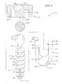
- FIG. 1is a side view of an embodiment of an unassembled pedicle screw according to the invention.
- FIG. 2 ais a side view of an embodiment of a partially assembled pedicle screw according to the invention.
- FIG. 2 bis a front view of an embodiment of a partially assembled pedicle screw according to the invention.
- FIG. 2 cis a front partial cross-sectional view of an embodiment of a partially assembled pedicle screw according to the invention.
- FIG. 3 ais a top view of an embodiment of a securing nut according to the invention.
- FIG. 3 bis a cross section of an embodiment of a securing nut according to the invention.
- FIG. 3 cis a side view of an embodiment of a securing nut according to the invention.
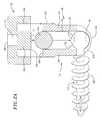
- FIG. 4 ais a side view of the interrelation of an embodiment of a pedicle screw and screw driver according to the invention.
- FIG. 4 bis a cross section of the interrelation of an embodiment of a pedicle screw and screw driver according to the invention.
- FIG. 5is a side view of an assembled pedicle screw according to the invention.
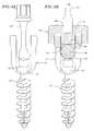
- FIG. 6is a schematic view of the manipulation and alignment of the spine utilizing an embodiment of the vertebral alignment/fixation system according to the invention.
- FIG. 7is a schematic view of the manipulation and alignment of the spine utilizing an embodiment of the vertebral alignment/fixation system according to the invention.
- the present inventionrelates generally to a method and apparatus for aligning and fixing vertebral bodies. More specifically, the present invention is directed to a system and method which allows a surgeon to manipulate the angular alignment of the fixation hardware of a vertebral alignment/fixation system after insertion and fixation of the pedicle screws into the vertebral bodies using freely rotatable couplers mounted to hemispherical pedicle screws. The system and method is further designed to enable the fixation of the angular alignment and installation and fixation of the alignment rods to the couplers by application of a single securing nut.
- the vertebral alignment/fixation assembly 10 of the current inventionconsists of three main components: a hemispherical pedicle screw 12 , a coupler unit 14 which functions as a universal joint, and a securing nut 16 .
- the hemispherical pedicle screw 12as shown in FIG. 1, comprises a substantially hemispherical head portion 18 , a neck portion 20 and a shaft portion 22 .
- the shaft 22is shown as having a generally cylindrical body 24 and a tapered tip 26 with a thread 28 dispose along the length of the shaft 22 , any shaft design, thread pitch or tip taper suitable for insertion into a vertebral body can be utilized in the current invention.
- the tapered tip 26 of the pedicle screw shaft 22further comprises a slotted groove 30 running longitudinally along the shaft, designed such that the screw is self-tapping easing the insertion of the pedicle screw 12 into the vertebral body.
- the head portion 18 of the pedicle screw 12comprises a substantially hemispherical shape.
- the substantially hemispherical shape of the head portion 18 of the screw 12is a portion or section of a sphere.
- the section or portion of the sphere comprising the head 18 of the screw 12is greater in extent than a hemisphere, it should be understood that any external contour which is equidistant from a center point of the head portion 18 could be utilized.
- the major cross-section of the substantially hemispherical head portion 18includes at least 270 degrees of a circle.
- the hemispherical head portion 18also has a recess 32 disposed therein (shown in phantom in FIG. 1 ).
- the recess 32defines a engagement point for the application of torque from a torque driving tool 33 for driving the screw 12 into a bone.
- the specific shape of the recess 32may be chosen to cooperate with any suitable screw-driving tool 33 , as shown in FIGS. 4 a and 4 b .
- the recess 32may comprise a slot for a flat-headed screwdriver, a crossed recess for a phillips head screwdriver, a hexagonally shaped hole for receiving an allen wrench, or a “figure- 8 ” shaped driver.
- a square-headed hole for a square screwdriver or socket-type wrenchis utilized.
- the recess 32is shown to be co-axial with the general elongate axis of the screw shaft 22 , it should be understood that any arrangement of recess 32 and screw 12 can be utilized such that sufficient torque may be applied to the screw 12 to drive it into a bone.
- the head portion 18 of the screw 12is connected to the shaft portion 22 at a neck portion 20 .
- the diameter of the shaft 22should be less than the diameter of the semi-spherical head 18
- the neck 20 of the screw 12should be preferably narrower than the widest portion of the shaft 22 .
- a pedicle screw 12 according to the invention having such dimensional relationshipsis preferable because the screw may be locked at a variety of angles with relation to the coupling unit 14 while still being securely joined to the coupling element 14 (embodiments of which are shown in FIGS. 1, 2 and 5 ).
- the pedicle screw 12is preferably made from surgical grade titanium or stainless steel.
- the coupling element 14comprises a generally cylindrical tubular body which defines an inner passage 34 having an inner wall 36 .
- the inner passage 34comprises an upper generally cylindrical portion 38 and an inwardly curved lower portion 40 .
- the inwardly curved lower portion 40defines a socket, into which the head 18 of the screw 12 may rotatingly engage.
- the bottom surface 42 of the coupling element 14includes an opening 44 defining a passage 46 such that the shaft 22 of the screw 12 may extend therethrough and pass outside the body of the coupling element 14 .
- the dimensions of the opening 44 and passage 46must be greater than the diameter of the shaft 22 of the screw 12 , but less than the largest diameter of the head 18 .
- the cylindrical upper portion 38 of the coupling element 14includes a pair of vertically oriented, channels 48 having rounded bottom surfaces 50 and open top portions disposed on opposing sides of the coupling element 14 .
- the channels 48form engagement point for an elongated fixation rod 60 .
- the channels 48divide the wall 52 of the coupling element 14 into upwardly extending members 54 and 56 . As shown in the embodiment illustrated in FIGS. 1, 2 and 5 , the vertical distance from the top 58 of the channels 48 to the curved bottom 50 , is sufficient to allow the rod 60 which is to be provided to slidingly engage therein such that the rod 60 may be fully nested in the channels 48 .
- the curved bottom 50 of the channels 48are arranged such that the top of the head 18 of the screw 12 , when fully nested in the lower socket portion 40 , extends above the edge of the curved bottom 50 of the channels 48 such that a rod 60 positioned therein will pressingly engage the head portion 18 of the screw 12 .
- the top 58 of the upper portion 38 of the coupling element 14which comprises upwardly extending members 54 and 56 , have disposed thereon a threading 62 .
- the upper portion 38 , and the threading 62 thereon,is ideally suited for threadingly engage a securing nut 16 .
- FIGS. 2 a , 2 b and 2 cshow an additional feature of one exemplary embodiment of the invention, which allows angular alignment of the screw 12 up to at least a 90 degree angle with respect to the coupling element 14 .
- the lower portion 40 of the coupling unit 14further comprises a pair of lower slots 63 extending from the opening 44 and passage 46 in the bottom surface 42 of the coupling unit 14 .
- the lower slots 63are aligned on opposite sides of the bottom surface 42 of the coupling unit 14 such that in combination the slots 63 define a single 180 degree passage dimensioned to allow the neck portion 20 of the screw 12 to move therein when the head portion 18 of the screw is fully engaged in the socket 40 of the coupling unit 14 and the coupling unit 14 is properly oriented with respect to the shaft 22 of the screw 12 .
- the coupling unit 14is designed such that a rod 60 inserted into the channels 48 will press against the head portion 18 of the screw 12 and at the urging of the securing nut 16 engage and fix both the rod 60 and in turn the coupling unit 14 into alignment.
- the top securing nut 16is shown in top view in FIG. 3 a , in side view in FIG. 3 b , and in cross section in FIG. 3 c .
- the nut 16comprises an inner threading 64 , which is intended to mate with the threading 62 on the upwardly extending members 54 and 56 of the upper portion 38 of the coupling element 14 .
- the nut 16also comprises an inner plug portion 65 having a bottom surface 66 which is intended to seat against the top surface of the rod 60 seated in the coupling element 14 , providing a means for driving the rod 60 downward and against the head portion 18 of the screw 12 .
- a central annular opening 68is provided in the center of the nut 16 defining a passage 70 passing therethrough, the passage 70 and opening 68 being designed such that the screw driver utilized to drive the screw 12 into the vertebral body can fit therein and can be utilized to tighten the nut 16 onto the coupling unit 14 , as shown in FIG. 4 b .
- the embodiment of the passage 70 shown in FIGS. 3 a to 3 cterminates in the middle of the plug 65 of the nut 16 , the passage 70 could also transect the plug 65 forming a conduit between the opening 68 and the bottom surface 66 .
- the bottom surface 66 of the nut 16further comprises a plurality of raised metal teeth 72 designed to bitingly engage and press into the rod 60 providing additional frictional engagement between the rod 60 and the vertebral alignment assembly 10 such that the possibility of a mechanical shock jarring the rod 60 loose from the vertebral alignment assembly 10 is reduced.
- the rod 60is manufactured with a rolled or corrugated finish to improve the frictional engagement between the rod 60 and the teeth 72 on the bottom surface 66 of the nut 16 .
- FIGS. 4 a and 4 bshow the engagement of a driver 33 with the vertebral alignment assembly 10 to first engage the screw 12 into the vertebral body 74 , as shown in FIG. 4 a , and then to engage the securing nut 16 onto the coupling unit 14 , as shown in FIG. 4 b .
- the coupler unit 14is designed such that the screw driver 33 can fit inside the inner passage 34 of the coupler 14 and engage the recess 32 of the head portion 18 of the screw 12 to drive the screw 12 into the vertebral body 74 .
- FIG. 4 athe coupler unit 14 is designed such that the screw driver 33 can fit inside the inner passage 34 of the coupler 14 and engage the recess 32 of the head portion 18 of the screw 12 to drive the screw 12 into the vertebral body 74 .
- the securing nut 16is further designed such that the screw driver 33 can engage nut opening 68 to secure the nut 16 on the coupling unit 14 and thereby fix alignment rod 60 into coupling unit 14 and further secure the alignment of the coupling unit 14 in relation to the axis of the screw 12 .
- the coupling element 14is shown with the screw 12 inserted therethrough, and the head 18 of the screw 12 nested in the lower socket portion 40 of the coupling element 14 .
- the shaft portion 22 of the screw 12is inserted downward, through the interior passage 34 of the coupling element 14 , and out through the opening 44 .
- the curved undersurface of the head portion 18rests against the inwardly curved bottom surface 42 of the lower socket 745 portion 40 , and is prevented from translating further downward by the dimensions of the opening 44 .
- the uppersurface of the head portion 18is pressed against the rod 60 which is pressed into the head portion 18 by securing nut 16 thereby simultaneously preventing the rod 60 from moving out of the coupling unit 14 and preventing the coupling unit 14 from moving relative to the screw 12 .
- FIGS. 6 and 7show a side view of the fully locked coupling element, rod, and screw system in relation to a vertebral body 74 .
- FIG. 6shows the vertebral alignment/fixation assembly 10 of the invention anchored traditionally in a plurality of vertebral bodies with an optional crosslink stabilizing bar.
- FIG. 7shows the vertebral alignment/fixation assembly 10 of the invention anchored into the ileum bone with the screw 12 aligned at a 90° angle with reference to the coupling unit 14 .
- the preferred method of assembly and alignment of vertebral bodiesis described.
- a pre-drilled hole 76is provided in the bone 74 , into which the screw 12 is to be anchored.
- the hole 76may be pretapped, or, as described above, the external threading 28 at the tip portion 24 of the screw 12 may include a self-tapping slot 30 .
- the tip 26 of the screw 12is inserted through the interior passage 34 of the coupling element 14 until the shaft 22 of the screw 22 extends out of the coupling element 14 and the head 18 of the screw 12 is engaged in the lower socket portion 40 of the coupling unit 14 .
- the coupling element 14has the capacity to rotate relative to the screw 12 .
- a screw-driving tool 33is then aligned with the recess 32 in the head 18 of the screw 12 so that it may be driven into the preformed hole 76 in the bone 74 .
- the coupling elementmay be rotated relative to the screw 12 , to align the coupling element 14 such that a support rod 60 may be engaged within the rod receiving channel 48 and properly aligned according to the surgeon's wishes. As shown best in FIG. 5, and previously discussed, the bottom of the rod 60 seats on the top of the head portion 18 of the screw 12 , and not fully on the bottom curved surface 50 of the channels 48 .
- the top locking nut 16is threaded onto the threading 62 of the upwardly extending members 54 and 56 .
- the nut 16is then screwed down onto the coupling element 14 until the lower surface 66 of the engaging portion 65 of the nut 16 seats against the top surface of the rod 60 .
- the rod 60is driven downward by the engaging portion 65 of the nut 16 , causing the rod 60 to engage the head 18 of the screw 12 and to push the head portion 18 of the 3 screw 18 downward pressingly engaging it within the socket 40 of the coupling element 14 .
- This downward translationpermits the bottom of the rod 60 to seat against the bottom surface 50 of the channels 48 , and causes the head 18 of the screw 12 to be crush locked to the inwardly curved surface 40 of the coupling element 14 .
- the forcealso engages the teeth 72 of the nut 16 into the rod 60 providing additional frictional engagement between the coupling element 14 and the rod 60 .
- the downward force of the bottom surface 66 of the nut 16 against the rod 60as well as the teeth 72 and the counter-force provided by the bottom surface 50 of the channels 48 causes the rod 60 to be locked.
- This lockingprevents the rod 60 from sliding relative to the assembled vertebral alignment assembly 10 , locking the rod 60 to the coupling element 14 , as well as the screw 12 to the coupling element 14 .
- fixation hardwarecould also be provided to fix the spine into the desired alignment.
- the fixation hardwaremay comprise clamps, which are designed to mate with the top or side of the pedicle screw, bendable fixation rods or plates, which run between the clamps on the various pedicle screws attached either to different vertebral bodies or at different points on a single vertebral body, and bolts, also designed to mate with the clamps such that the clamps can be tightened onto and fix the fixation rods into place.
- the fixation hardwaremay comprise crosslinks of any design suitable for attachment to the alignment assembly 10 of the current invention. For example, although the crosslink shown in FIG.
- slotted crosslinksmay also be used for applications in which the distance between the fixation points of the crosslink must be changed.
- the openings in the crosslink for attaching it to the alignment assembly 10(which are shown as simple holes in FIG. 6) comprise elongated slots such that the crosslink may be slid relative to the alignment assembly 10 along the length of the slot, thereby allowing for some degree of adjustment in the position of the crosslink relative to the alignment assembly.
- fixation hardwarecan be made of any suitable surgical material, such as, for example, stainless steel or titanium.
Landscapes
- Health & Medical Sciences (AREA)
- Orthopedic Medicine & Surgery (AREA)
- Life Sciences & Earth Sciences (AREA)
- Neurology (AREA)
- Surgery (AREA)
- Heart & Thoracic Surgery (AREA)
- Engineering & Computer Science (AREA)
- Biomedical Technology (AREA)
- Nuclear Medicine, Radiotherapy & Molecular Imaging (AREA)
- Medical Informatics (AREA)
- Molecular Biology (AREA)
- Animal Behavior & Ethology (AREA)
- General Health & Medical Sciences (AREA)
- Public Health (AREA)
- Veterinary Medicine (AREA)
- Surgical Instruments (AREA)
- Prostheses (AREA)
Abstract
Description
Claims (18)
Priority Applications (1)
| Application Number | Priority Date | Filing Date | Title |
|---|---|---|---|
| US09/928,640US6520963B1 (en) | 2001-08-13 | 2001-08-13 | Vertebral alignment and fixation assembly |
Applications Claiming Priority (1)
| Application Number | Priority Date | Filing Date | Title |
|---|---|---|---|
| US09/928,640US6520963B1 (en) | 2001-08-13 | 2001-08-13 | Vertebral alignment and fixation assembly |
Publications (2)
| Publication Number | Publication Date |
|---|---|
| US20030032957A1 US20030032957A1 (en) | 2003-02-13 |
| US6520963B1true US6520963B1 (en) | 2003-02-18 |
Family
ID=25456558
Family Applications (1)
| Application Number | Title | Priority Date | Filing Date |
|---|---|---|---|
| US09/928,640Expired - LifetimeUS6520963B1 (en) | 2001-08-13 | 2001-08-13 | Vertebral alignment and fixation assembly |
Country Status (1)
| Country | Link |
|---|---|
| US (1) | US6520963B1 (en) |
Cited By (128)
| Publication number | Priority date | Publication date | Assignee | Title |
|---|---|---|---|---|
| US20020133159A1 (en)* | 2000-12-08 | 2002-09-19 | Jackson Roger P. | Closure for open-headed medical implant |
| US6641586B2 (en)* | 2002-02-01 | 2003-11-04 | Depuy Acromed, Inc. | Closure system for spinal fixation instrumentation |
| US20040049273A1 (en)* | 1999-10-22 | 2004-03-11 | Archus Orthopedics, Inc. | Facet Arthroplasty devices and methods |
| US20040097926A1 (en)* | 2001-03-06 | 2004-05-20 | Sung-Kon Kim | Screw for fixing spine |
| US20040127900A1 (en)* | 2002-12-31 | 2004-07-01 | Konieczynski David D. | Resilient bone plate and screw system allowing bi-directional assembly |
| US20040138660A1 (en)* | 2003-01-10 | 2004-07-15 | Serhan Hassan A. | Locking cap assembly for spinal fixation instrumentation |
| US20040153077A1 (en)* | 2000-11-10 | 2004-08-05 | Lutz Biedermann | Bone screw |
| US20040153078A1 (en)* | 2003-01-30 | 2004-08-05 | Grinberg Alexander D | Anterior buttress staple |
| US20040167526A1 (en)* | 2002-09-06 | 2004-08-26 | Roger P. Jackson | Closure for rod receiving orthopedic implant having left handed thread removal |
| US20040172032A1 (en)* | 2002-09-06 | 2004-09-02 | Jackson Roger P. | Anti-splay medical implant closure with multi-surface removal aperture |
| US20040199164A1 (en)* | 2002-09-06 | 2004-10-07 | Jackson Roger P. | Helical wound mechanically interlocking mating guide and advancement structure |
| US20040230201A1 (en)* | 2003-05-14 | 2004-11-18 | Archus Orthopedics Inc. | Prostheses, tools and methods for replacement of natural facet joints with artifical facet joint surfaces |
| US20040230304A1 (en)* | 2003-05-14 | 2004-11-18 | Archus Orthopedics Inc. | Prostheses, tools and methods for replacement of natural facet joints with artifical facet joint surfaces |
| US20040236330A1 (en)* | 2003-05-22 | 2004-11-25 | Thomas Purcell | Variable angle spinal screw assembly |
| US20040254577A1 (en)* | 2001-10-18 | 2004-12-16 | Joel Delecrin | Progressive approach osteosynthesis device and preassembly method |
| US20040267264A1 (en)* | 2003-06-27 | 2004-12-30 | Konieczynski David D. | Polyaxial bone screw |
| US20050038430A1 (en)* | 2003-08-11 | 2005-02-17 | Mckinley Laurence M. | Low profile vertebral alignment and fixation assembly |
| WO2005018470A1 (en)* | 2003-08-11 | 2005-03-03 | Mckinley Laurence M | Low profile vertebral alignment and fixation assembly |
| US20050080415A1 (en)* | 2003-10-14 | 2005-04-14 | Keyer Thomas R. | Polyaxial bone anchor and method of spinal fixation |
| US20050119748A1 (en)* | 1999-10-22 | 2005-06-02 | Reiley Mark A. | Prostheses, systems and methods for replacement of natural facet joints with artificial facet joint surfaces |
| US20050131406A1 (en)* | 2003-12-15 | 2005-06-16 | Archus Orthopedics, Inc. | Polyaxial adjustment of facet joint prostheses |
| US20050143818A1 (en)* | 2003-05-14 | 2005-06-30 | Hansen Yuan | Prostheses, tools and methods for replacement of natural facet joints with artifical facet joint surfaces |
| US20050154393A1 (en)* | 2003-12-30 | 2005-07-14 | Thomas Doherty | Bone anchor assemblies and methods of manufacturing bone anchor assemblies |
| US20050154391A1 (en)* | 2003-12-30 | 2005-07-14 | Thomas Doherty | Bone anchor assemblies |
| US20050182410A1 (en)* | 2002-09-06 | 2005-08-18 | Jackson Roger P. | Helical guide and advancement flange with radially loaded lip |
| US20050240266A1 (en)* | 2004-04-22 | 2005-10-27 | Kuiper Mark K | Crossbar spinal prosthesis having a modular design and related implantation methods |
| US20050277919A1 (en)* | 2004-05-28 | 2005-12-15 | Depuy Spine, Inc. | Anchoring systems and methods for correcting spinal deformities |
| US20050283157A1 (en)* | 2004-06-17 | 2005-12-22 | Coates Bradley J | Multi-axial bone attachment assembly |
| US20060009773A1 (en)* | 2002-09-06 | 2006-01-12 | Jackson Roger P | Helical interlocking mating guide and advancement structure |
| US20060036252A1 (en)* | 2004-08-12 | 2006-02-16 | Baynham Bret O | Polyaxial screw |
| US20060041311A1 (en)* | 2004-08-18 | 2006-02-23 | Mcleer Thomas J | Devices and methods for treating facet joints |
| WO2006023671A1 (en) | 2004-08-18 | 2006-03-02 | Archus Orthopedics, Inc. | Adjacent level facet arthroplasty devices, spine stabilization systems, and methods |
| US20060079895A1 (en)* | 2004-09-30 | 2006-04-13 | Mcleer Thomas J | Methods and devices for improved bonding of devices to bone |
| US20060085072A1 (en)* | 2004-04-22 | 2006-04-20 | Archus Orthopedics, Inc. | Implantable orthopedic device component selection instrument and methods |
| US20060085075A1 (en)* | 2004-10-04 | 2006-04-20 | Archus Orthopedics, Inc. | Polymeric joint complex and methods of use |
| US20060100707A1 (en)* | 2003-07-08 | 2006-05-11 | David Stinson | Prostheses, tools and methods for replacement of natural facet joints with artificial facet joint surfaces |
| US20060111718A1 (en)* | 2002-07-12 | 2006-05-25 | Olivier Carli | Bone anchoring device with spherical articulation |
| US20060116687A1 (en)* | 2004-11-30 | 2006-06-01 | Miller Keith E | Side-loading adjustable bone anchor |
| US20060149232A1 (en)* | 2004-12-15 | 2006-07-06 | Sasing Jude L | Multi-axial bone screw mechanism |
| US20060166535A1 (en)* | 2005-01-26 | 2006-07-27 | Brumfield David L | Reducing instrument for spinal surgery |
| US20060184180A1 (en)* | 2004-04-22 | 2006-08-17 | Augostino Teena M | Facet Joint Prosthesis Measurement and Implant Tools |
| US20060200128A1 (en)* | 2003-04-04 | 2006-09-07 | Richard Mueller | Bone anchor |
| US20060217716A1 (en)* | 2005-03-22 | 2006-09-28 | Baker Daniel R | Spinal fixation locking mechanism |
| US20060235385A1 (en)* | 2005-03-31 | 2006-10-19 | Dale Whipple | Low profile polyaxial screw |
| US20060241603A1 (en)* | 2003-06-18 | 2006-10-26 | Jackson Roger P | Polyaxial bone screw assembly with fixed retaining structure |
| US20060241623A1 (en)* | 2005-04-08 | 2006-10-26 | Sdgi Holdings, Inc. | Slotted screw for use with a vertebral member |
| US20070050757A1 (en)* | 2005-08-25 | 2007-03-01 | Microsoft Corporation | Automated analysis and recovery of localization data |
| US20070055242A1 (en)* | 2005-07-27 | 2007-03-08 | Bailly Frank E | Device for securing spinal rods |
| US20070088358A1 (en)* | 2005-03-22 | 2007-04-19 | Hansen Yuan | Minimally Invasive Spine Restoration Systems, Devices, Methods and Kits |
| US20070093833A1 (en)* | 2004-05-03 | 2007-04-26 | Kuiper Mark K | Crossbar spinal prosthesis having a modular design and related implantation methods |
| US20070090238A1 (en)* | 2005-10-20 | 2007-04-26 | Sdgi Holdings, Inc. | Bottom loading multi-axial screw assembly |
| US20070118123A1 (en)* | 2005-11-21 | 2007-05-24 | Strausbaugh William L | Polyaxial bone anchors with increased angulation |
| US20070173822A1 (en)* | 2006-01-13 | 2007-07-26 | Sdgi Holdings, Inc. | Use of a posterior dynamic stabilization system with an intradiscal device |
| US20070233256A1 (en)* | 2006-03-15 | 2007-10-04 | Ohrt John A | Facet and disc arthroplasty system and method |
| US20070233068A1 (en)* | 2006-02-22 | 2007-10-04 | Sdgi Holdings, Inc. | Intervertebral prosthetic assembly for spinal stabilization and method of implanting same |
| US20070265621A1 (en)* | 2006-04-06 | 2007-11-15 | Wilfried Matthis | Bone anchoring device |
| US20070270811A1 (en)* | 2006-04-14 | 2007-11-22 | Sdgi Holdings, Inc. | Reducing device |
| US20070276374A1 (en)* | 2005-03-02 | 2007-11-29 | Richard Broman | Arthroplasty revision system and method |
| US20080015579A1 (en)* | 2006-04-28 | 2008-01-17 | Whipple Dale E | Large diameter bone anchor assembly |
| US20080045954A1 (en)* | 1999-10-22 | 2008-02-21 | Reiley Mark A | Prostheses, systems and methods for replacement of natural facet joints with artificial facet joint surfaces |
| US20080082171A1 (en)* | 2004-04-22 | 2008-04-03 | Kuiper Mark K | Crossbar spinal prosthesis having a modular design and systems for treating spinal pathologies |
| US20080091200A1 (en)* | 2004-04-22 | 2008-04-17 | Kuiper Mark K | Crossbar spinal prosthesis having a modular design and related implantation methods |
| US20080097612A1 (en)* | 1999-10-22 | 2008-04-24 | Reiley Mark A | Facet Arthroplasty Devices and Methods |
| US20080097457A1 (en)* | 2004-10-25 | 2008-04-24 | Warnick David R | Pedicle screw systems and methods of assembling/installing the same |
| US20080103502A1 (en)* | 2006-04-26 | 2008-05-01 | Warsaw Orthopedic, Inc. | Revision Fixation Plate and Method of Use |
| US20080103501A1 (en)* | 2006-08-11 | 2008-05-01 | Ralph Christopher R | Angled Washer Polyaxial Connection for Dynamic Spine Prosthesis |
| US20080132953A1 (en)* | 2001-09-14 | 2008-06-05 | Stryker Spine | Methods for stabilizing bone using spinal fixation devices |
| US20080161863A1 (en)* | 2006-12-28 | 2008-07-03 | Depuy Spine, Inc. | Spinal anchoring screw |
| US20080177310A1 (en)* | 2000-10-20 | 2008-07-24 | Archus Orthopedics, Inc. | Facet arthroplasty devices and methods |
| US20080177322A1 (en)* | 2006-12-29 | 2008-07-24 | Melissa Davis | Spinal stabilization systems and methods |
| US20080249576A1 (en)* | 2005-10-25 | 2008-10-09 | Hawkes David T | Pedicle Screw System Configured to Receive a Straight or Curved Rod |
| US20080249570A1 (en)* | 2007-04-06 | 2008-10-09 | Warsaw Orthopedic, Inc. | Adjustable multi-axial spinal coupling assemblies |
| US20080288002A1 (en)* | 2006-12-29 | 2008-11-20 | Abbott Spine Inc. | Spinal Stabilization Systems and Methods |
| US20090163955A1 (en)* | 2007-12-19 | 2009-06-25 | Missoum Moumene | Polymeric Pedicle Rods and Methods of Manufacturing |
| US20100016904A1 (en)* | 2003-06-18 | 2010-01-21 | Jackson Roger P | Upload shank swivel head bone screw spinal implant |
| US20100087873A1 (en)* | 2008-10-06 | 2010-04-08 | Warsaw Orthopedics, Inc. | Surgical Connectors for Attaching an Elongated Member to a Bone |
| US20100160978A1 (en)* | 2008-12-23 | 2010-06-24 | John Carbone | Bone screw assembly with non-uniform material |
| US20100211104A1 (en)* | 2009-02-13 | 2010-08-19 | Missoum Moumene | Dual Spring Posterior Dynamic Stabilization Device With Elongation Limiting Elastomers |
| US20100211114A1 (en)* | 2003-06-18 | 2010-08-19 | Jackson Roger P | Polyaxial bone anchor with shelf capture connection |
| US7811310B2 (en) | 2005-05-04 | 2010-10-12 | Spinefrontier, Inc | Multistage spinal fixation locking mechanism |
| US20100262195A1 (en)* | 2005-05-27 | 2010-10-14 | Jackson Roger P | Polyaxial bone screw with shank articulation pressure insert and method |
| US20100318136A1 (en)* | 2003-06-18 | 2010-12-16 | Jackson Roger P | Polyaxial bone screw assembly |
| US20100331886A1 (en)* | 2009-06-25 | 2010-12-30 | Jonathan Fanger | Posterior Dynamic Stabilization Device Having A Mobile Anchor |
| US20110034957A1 (en)* | 2009-07-28 | 2011-02-10 | Markku Biedermann | Bone anchoring device |
| US20110093021A1 (en)* | 2009-10-16 | 2011-04-21 | Jonathan Fanger | Bone Anchor Assemblies and Methods of Manufacturing and Use Thereof |
| US20110112578A1 (en)* | 2009-11-09 | 2011-05-12 | Ebi, Llc | Multiplanar bone anchor system |
| US7981142B2 (en) | 2002-12-31 | 2011-07-19 | Depuy Spine, Inc. | Bone plate and screw system allowing bi-directional assembly |
| US8016866B2 (en) | 2005-10-04 | 2011-09-13 | X-Spine Systems, Inc. | Pedicle screw system with provisional locking aspects |
| US20110238119A1 (en)* | 2010-03-24 | 2011-09-29 | Missoum Moumene | Composite Material Posterior Dynamic Stabilization Spring Rod |
| US8066745B2 (en) | 2005-07-29 | 2011-11-29 | X-Spine Systems, Inc. | Capless multiaxial screw and spinal fixation assembly and method |
| US8083795B2 (en) | 2006-01-18 | 2011-12-27 | Warsaw Orthopedic, Inc. | Intervertebral prosthetic device for spinal stabilization and method of manufacturing same |
| US20120010643A1 (en)* | 2009-04-03 | 2012-01-12 | Weixing Shao | Puncture needle for orthopedic operation |
| US8137386B2 (en) | 2003-08-28 | 2012-03-20 | Jackson Roger P | Polyaxial bone screw apparatus |
| US8147522B2 (en) | 2004-10-25 | 2012-04-03 | X-Spine Systems, Inc. | Bone fixation method |
| US8221461B2 (en) | 2004-10-25 | 2012-07-17 | Gmedelaware 2 Llc | Crossbar spinal prosthesis having a modular design and systems for treating spinal pathologies |
| US8328807B2 (en) | 2008-07-09 | 2012-12-11 | Icon Orthopaedic Concepts, Llc | Ankle arthrodesis nail and outrigger assembly |
| US8337530B2 (en) | 2011-03-09 | 2012-12-25 | Zimmer Spine, Inc. | Polyaxial pedicle screw with increased angulation |
| US8357181B2 (en) | 2005-10-27 | 2013-01-22 | Warsaw Orthopedic, Inc. | Intervertebral prosthetic device for spinal stabilization and method of implanting same |
| US8361129B2 (en) | 2006-04-28 | 2013-01-29 | Depuy Spine, Inc. | Large diameter bone anchor assembly |
| US8414584B2 (en) | 2008-07-09 | 2013-04-09 | Icon Orthopaedic Concepts, Llc | Ankle arthrodesis nail and outrigger assembly |
| US8496686B2 (en) | 2005-03-22 | 2013-07-30 | Gmedelaware 2 Llc | Minimally invasive spine restoration systems, devices, methods and kits |
| US8814913B2 (en) | 2002-09-06 | 2014-08-26 | Roger P Jackson | Helical guide and advancement flange with break-off extensions |
| US8936623B2 (en) | 2003-06-18 | 2015-01-20 | Roger P. Jackson | Polyaxial bone screw assembly |
| US9044272B2 (en) | 2009-11-09 | 2015-06-02 | Ebi, Llc | Multiplanar bone anchor system |
| US9060818B2 (en) | 2011-09-01 | 2015-06-23 | DePuy Synthes Products, Inc. | Bone implants |
| US9414863B2 (en) | 2005-02-22 | 2016-08-16 | Roger P. Jackson | Polyaxial bone screw with spherical capture, compression insert and alignment and retention structures |
| USRE46115E1 (en) | 2005-09-19 | 2016-08-23 | Ebi, Llc | Bone screw apparatus, system and method |
| US9486256B1 (en) | 2013-03-15 | 2016-11-08 | Nuvasive, Inc. | Rod reduction assemblies and related methods |
| US20160341245A1 (en)* | 2014-12-05 | 2016-11-24 | Black & Decker Inc. | Swivel hanger system |
| US9549765B2 (en) | 2014-04-03 | 2017-01-24 | Zimmer Spine, Inc. | Uniplanar bone screw |
| US9763699B2 (en) | 2001-04-06 | 2017-09-19 | Ldr Medical | Spinal osteosynthesis device and preparation method |
| US9763700B1 (en) | 2016-12-14 | 2017-09-19 | Spine Wave, Inc. | Polyaxial bone screw |
| US9974571B2 (en) | 2008-09-12 | 2018-05-22 | DePuy Synthes Products, Inc. | Spinal stabilizing and guiding fixation system |
| US20180283443A1 (en)* | 2014-12-05 | 2018-10-04 | Black & Decker Inc. | Swivel hanger |
| US10105163B2 (en) | 2009-04-15 | 2018-10-23 | DePuy Synthes Products, Inc. | Revision connector for spinal constructs |
| US20180317973A1 (en)* | 2017-05-03 | 2018-11-08 | Advance Research System, Llc | Reinforcement caps for spinal support systems |
| US10136923B2 (en) | 2007-07-20 | 2018-11-27 | DePuy Synthes Products, Inc. | Polyaxial bone fixation element |
| US10136927B1 (en) | 2013-03-15 | 2018-11-27 | Nuvasive, Inc. | Rod reduction assemblies and related methods |
| US10149702B2 (en) | 2015-01-12 | 2018-12-11 | Imds Llc | Polyaxial screw and rod system |
| US10154859B2 (en) | 2008-09-29 | 2018-12-18 | DePuy Synthes Products, Inc. | Polyaxial bottom-loading screw and rod assembly |
| US10299839B2 (en) | 2003-12-16 | 2019-05-28 | Medos International Sárl | Percutaneous access devices and bone anchor assemblies |
| US10335200B2 (en) | 2007-09-17 | 2019-07-02 | Roger P. Jackson | Pivotal bone anchor assembly with twist-in-place insert having alignment notches |
| US10405892B2 (en) | 2008-11-03 | 2019-09-10 | DePuy Synthes Products, Inc. | Uni-planer bone fixation assembly |
| US10952777B2 (en) | 2003-04-09 | 2021-03-23 | Roger P. Jackson | Pivotal bone screw assembly with receiver having threaded open channel and lower opening |
| US11006978B2 (en) | 2009-06-17 | 2021-05-18 | DePuy Synthes Products, Inc. | Revision connector for spinal constructs |
| US11051861B2 (en) | 2018-06-13 | 2021-07-06 | Nuvasive, Inc. | Rod reduction assemblies and related methods |
| US11419642B2 (en) | 2003-12-16 | 2022-08-23 | Medos International Sarl | Percutaneous access devices and bone anchor assemblies |
| US11648037B2 (en) | 2017-05-03 | 2023-05-16 | Advance Research System, Llc | Extension-ready spinal support system with vascular-safe pedicle screw |
Families Citing this family (54)
| Publication number | Priority date | Publication date | Assignee | Title |
|---|---|---|---|---|
| US7833250B2 (en) | 2004-11-10 | 2010-11-16 | Jackson Roger P | Polyaxial bone screw with helically wound capture connection |
| US7766915B2 (en) | 2004-02-27 | 2010-08-03 | Jackson Roger P | Dynamic fixation assemblies with inner core and outer coil-like member |
| US7967850B2 (en) | 2003-06-18 | 2011-06-28 | Jackson Roger P | Polyaxial bone anchor with helical capture connection, insert and dual locking assembly |
| AU2004266737B2 (en)* | 2003-08-20 | 2010-05-13 | Warsaw Orthopedic, Inc. | Multi-axial orthopedic device and system, e.g. for spinal surgery |
| DE102004010380A1 (en)* | 2004-03-03 | 2005-09-22 | Biedermann Motech Gmbh | Anchoring element and stabilizing device for the dynamic stabilization of vertebrae or bones with such an anchoring element |
| US20050228380A1 (en)* | 2004-04-09 | 2005-10-13 | Depuy Spine Inc. | Instruments and methods for minimally invasive spine surgery |
| US7648520B2 (en)* | 2004-04-16 | 2010-01-19 | Kyphon Sarl | Pedicle screw assembly |
| US7524323B2 (en)* | 2004-04-16 | 2009-04-28 | Kyphon Sarl | Subcutaneous support |
| EP1740112A1 (en)* | 2004-04-16 | 2007-01-10 | Kyphon Inc. | Screw assembly |
| US7811311B2 (en)* | 2004-12-30 | 2010-10-12 | Warsaw Orthopedic, Inc. | Screw with deployable interlaced dual rods |
| US7618418B2 (en)* | 2004-04-16 | 2009-11-17 | Kyphon Sarl | Plate system for minimally invasive support of the spine |
| US7789899B2 (en) | 2004-12-30 | 2010-09-07 | Warsaw Orthopedic, Inc. | Bone anchorage screw with built-in hinged plate |
| US8226690B2 (en) | 2005-07-22 | 2012-07-24 | The Board Of Trustees Of The Leland Stanford Junior University | Systems and methods for stabilization of bone structures |
| US8267969B2 (en)* | 2004-10-20 | 2012-09-18 | Exactech, Inc. | Screw systems and methods for use in stabilization of bone structures |
| US8926672B2 (en) | 2004-11-10 | 2015-01-06 | Roger P. Jackson | Splay control closure for open bone anchor |
| US9168069B2 (en) | 2009-06-15 | 2015-10-27 | Roger P. Jackson | Polyaxial bone anchor with pop-on shank and winged insert with lower skirt for engaging a friction fit retainer |
| US8444681B2 (en) | 2009-06-15 | 2013-05-21 | Roger P. Jackson | Polyaxial bone anchor with pop-on shank, friction fit retainer and winged insert |
| US7901437B2 (en) | 2007-01-26 | 2011-03-08 | Jackson Roger P | Dynamic stabilization member with molded connection |
| US20060229607A1 (en)* | 2005-03-16 | 2006-10-12 | Sdgi Holdings, Inc. | Systems, kits and methods for treatment of the spinal column using elongate support members |
| US8523865B2 (en) | 2005-07-22 | 2013-09-03 | Exactech, Inc. | Tissue splitter |
| CH705709B1 (en)* | 2005-08-29 | 2013-05-15 | Bird Biedermann Ag | Spinal implant. |
| US7918857B2 (en) | 2006-09-26 | 2011-04-05 | Depuy Spine, Inc. | Minimally invasive bone anchor extensions |
| US8167910B2 (en) | 2006-10-16 | 2012-05-01 | Innovative Delta Technology Llc | Bone screw and associated assembly and methods of use thereof |
| US8096996B2 (en) | 2007-03-20 | 2012-01-17 | Exactech, Inc. | Rod reducer |
| AU2008206396A1 (en)* | 2007-01-12 | 2008-07-24 | Lanx, Inc. | Bone fastener assembly |
| US9962194B2 (en) | 2007-01-15 | 2018-05-08 | Innovative Delta Technology, Llc | Polyaxial spinal stabilizer connector and methods of use thereof |
| US7794478B2 (en) | 2007-01-15 | 2010-09-14 | Innovative Delta Technology, Llc | Polyaxial cross connector and methods of use thereof |
| US8979904B2 (en) | 2007-05-01 | 2015-03-17 | Roger P Jackson | Connecting member with tensioned cord, low profile rigid sleeve and spacer with torsion control |
| US8197517B1 (en) | 2007-05-08 | 2012-06-12 | Theken Spine, Llc | Frictional polyaxial screw assembly |
| US8414588B2 (en)* | 2007-10-04 | 2013-04-09 | Depuy Spine, Inc. | Methods and devices for minimally invasive spinal connection element delivery |
| AU2010260521C1 (en) | 2008-08-01 | 2013-08-01 | Roger P. Jackson | Longitudinal connecting member with sleeved tensioned cords |
| US20100198271A1 (en)* | 2009-02-02 | 2010-08-05 | Vincent Leone | Screw Sheath for Minimally Invasive Spinal Surgery and Method Relating Thereto |
| US8998959B2 (en) | 2009-06-15 | 2015-04-07 | Roger P Jackson | Polyaxial bone anchors with pop-on shank, fully constrained friction fit retainer and lock and release insert |
| CN103826560A (en) | 2009-06-15 | 2014-05-28 | 罗杰.P.杰克逊 | Polyaxial Bone Anchor with Socket Stem and Winged Inserts with Friction Fit Compression Collars |
| US9668771B2 (en) | 2009-06-15 | 2017-06-06 | Roger P Jackson | Soft stabilization assemblies with off-set connector |
| US11229457B2 (en) | 2009-06-15 | 2022-01-25 | Roger P. Jackson | Pivotal bone anchor assembly with insert tool deployment |
| US9084634B1 (en) | 2010-07-09 | 2015-07-21 | Theken Spine, Llc | Uniplanar screw |
| US10603083B1 (en) | 2010-07-09 | 2020-03-31 | Theken Spine, Llc | Apparatus and method for limiting a range of angular positions of a screw |
| US20140018867A1 (en)* | 2011-02-04 | 2014-01-16 | Stefan Freudiger | Precaution against jamming on open bone screws |
| US8911479B2 (en) | 2012-01-10 | 2014-12-16 | Roger P. Jackson | Multi-start closures for open implants |
| CN102525626B (en)* | 2012-02-07 | 2013-06-05 | 陈远明 | Vertebral arch pedicle screw system capable of being embedded with minimal invasion |
| US8911478B2 (en) | 2012-11-21 | 2014-12-16 | Roger P. Jackson | Splay control closure for open bone anchor |
| US10058354B2 (en) | 2013-01-28 | 2018-08-28 | Roger P. Jackson | Pivotal bone anchor assembly with frictional shank head seating surfaces |
| US8852239B2 (en) | 2013-02-15 | 2014-10-07 | Roger P Jackson | Sagittal angle screw with integral shank and receiver |
| FR3005569B1 (en) | 2013-05-16 | 2021-09-03 | Ldr Medical | VERTEBRAL IMPLANT, VERTEBRAL IMPLANT FIXATION DEVICE AND IMPLANTATION INSTRUMENTATION |
| US9358060B2 (en)* | 2013-07-25 | 2016-06-07 | Zimmer Spine, Inc. | Self-retaining driver for a bone screw |
| US9566092B2 (en) | 2013-10-29 | 2017-02-14 | Roger P. Jackson | Cervical bone anchor with collet retainer and outer locking sleeve |
| US9717533B2 (en) | 2013-12-12 | 2017-08-01 | Roger P. Jackson | Bone anchor closure pivot-splay control flange form guide and advancement structure |
| US9451993B2 (en) | 2014-01-09 | 2016-09-27 | Roger P. Jackson | Bi-radial pop-on cervical bone anchor |
| US9597119B2 (en) | 2014-06-04 | 2017-03-21 | Roger P. Jackson | Polyaxial bone anchor with polymer sleeve |
| US10064658B2 (en) | 2014-06-04 | 2018-09-04 | Roger P. Jackson | Polyaxial bone anchor with insert guides |
| US20170252180A1 (en)* | 2016-03-02 | 2017-09-07 | Frank Acosta | Corpectomy cage system |
| US10507043B1 (en) | 2017-10-11 | 2019-12-17 | Seaspine Orthopedics Corporation | Collet for a polyaxial screw assembly |
| CN110916785B (en)* | 2019-12-17 | 2024-01-12 | 浙江德康医疗器械有限公司 | Thoracolumbar anterior system |
Citations (11)
| Publication number | Priority date | Publication date | Assignee | Title |
|---|---|---|---|---|
| US5443467A (en)* | 1993-03-10 | 1995-08-22 | Biedermann Motech Gmbh | Bone screw |
| US5474555A (en)* | 1990-04-26 | 1995-12-12 | Cross Medical Products | Spinal implant system |
| US5672176A (en)* | 1995-03-15 | 1997-09-30 | Biedermann; Lutz | Anchoring member |
| US5817094A (en)* | 1995-04-13 | 1998-10-06 | Fastenetix, Llc | Polyaxial locking screw and coupling element |
| US5882350A (en) | 1995-04-13 | 1999-03-16 | Fastenetix, Llc | Polyaxial pedicle screw having a threaded and tapered compression locking mechanism |
| US6010503A (en) | 1998-04-03 | 2000-01-04 | Spinal Innovations, Llc | Locking mechanism |
| US6132434A (en) | 1996-11-07 | 2000-10-17 | Sdgi Holdings, Inc. | Multi-angle bone screw assembly using shape-memory technology |
| US6132432A (en) | 1996-10-18 | 2000-10-17 | Spinal Innovations Llc | Spinal implant fixation assembly |
| US6280442B1 (en) | 1999-09-01 | 2001-08-28 | Sdgi Holdings, Inc. | Multi-axial bone screw assembly |
| US6440137B1 (en)* | 2000-04-18 | 2002-08-27 | Andres A. Horvath | Medical fastener cap system |
| US6443953B1 (en) | 2000-02-08 | 2002-09-03 | Cross Medical Products, Inc. | Self-aligning cap nut for use with a spinal rod anchor |
- 2001
- 2001-08-13USUS09/928,640patent/US6520963B1/ennot_activeExpired - Lifetime
Patent Citations (11)
| Publication number | Priority date | Publication date | Assignee | Title |
|---|---|---|---|---|
| US5474555A (en)* | 1990-04-26 | 1995-12-12 | Cross Medical Products | Spinal implant system |
| US5443467A (en)* | 1993-03-10 | 1995-08-22 | Biedermann Motech Gmbh | Bone screw |
| US5672176A (en)* | 1995-03-15 | 1997-09-30 | Biedermann; Lutz | Anchoring member |
| US5817094A (en)* | 1995-04-13 | 1998-10-06 | Fastenetix, Llc | Polyaxial locking screw and coupling element |
| US5882350A (en) | 1995-04-13 | 1999-03-16 | Fastenetix, Llc | Polyaxial pedicle screw having a threaded and tapered compression locking mechanism |
| US6132432A (en) | 1996-10-18 | 2000-10-17 | Spinal Innovations Llc | Spinal implant fixation assembly |
| US6132434A (en) | 1996-11-07 | 2000-10-17 | Sdgi Holdings, Inc. | Multi-angle bone screw assembly using shape-memory technology |
| US6010503A (en) | 1998-04-03 | 2000-01-04 | Spinal Innovations, Llc | Locking mechanism |
| US6280442B1 (en) | 1999-09-01 | 2001-08-28 | Sdgi Holdings, Inc. | Multi-axial bone screw assembly |
| US6443953B1 (en) | 2000-02-08 | 2002-09-03 | Cross Medical Products, Inc. | Self-aligning cap nut for use with a spinal rod anchor |
| US6440137B1 (en)* | 2000-04-18 | 2002-08-27 | Andres A. Horvath | Medical fastener cap system |
Non-Patent Citations (1)
| Title |
|---|
| PCT International Search Report dated Dec. 27, 2001 from corresponding PCT application No. PCT/US014684 filed Aug. 13, 2001. |
Cited By (329)
| Publication number | Priority date | Publication date | Assignee | Title |
|---|---|---|---|---|
| US8092532B2 (en) | 1999-10-22 | 2012-01-10 | Gmedelaware 2 Llc | Facet arthroplasty devices and methods |
| US7087084B2 (en) | 1999-10-22 | 2006-08-08 | Archus Orthopedics, Inc. | Method for replacing a natural facet joint with a prosthesis having an artificial facet joint structure |
| US20040049273A1 (en)* | 1999-10-22 | 2004-03-11 | Archus Orthopedics, Inc. | Facet Arthroplasty devices and methods |
| US20040049281A1 (en)* | 1999-10-22 | 2004-03-11 | Archus Orthopedics, Inc. | Facet arthroplasty devices and methods |
| US20060009849A1 (en)* | 1999-10-22 | 2006-01-12 | Reiley Mark A | Facet arthroplasty devices and methods |
| US20080045954A1 (en)* | 1999-10-22 | 2008-02-21 | Reiley Mark A | Prostheses, systems and methods for replacement of natural facet joints with artificial facet joint surfaces |
| US7608106B2 (en) | 1999-10-22 | 2009-10-27 | Archus Orthopedics, Inc. | Facet arthroplasty devices and methods |
| US20060009847A1 (en)* | 1999-10-22 | 2006-01-12 | Reiley Mark A | Facet arthroplasty devices and methods |
| US20080097612A1 (en)* | 1999-10-22 | 2008-04-24 | Reiley Mark A | Facet Arthroplasty Devices and Methods |
| US20080097613A1 (en)* | 1999-10-22 | 2008-04-24 | Reiley Mark A | Prostheses, Systems and Methods for Replacement of Natural Facet Joints With Artificial Facet Joint Surfaces |
| US7691145B2 (en) | 1999-10-22 | 2010-04-06 | Facet Solutions, Inc. | Prostheses, systems and methods for replacement of natural facet joints with artificial facet joint surfaces |
| US20050137706A1 (en)* | 1999-10-22 | 2005-06-23 | Reiley Mark A. | Facet arthroplasty devices and methods |
| US20050251256A1 (en)* | 1999-10-22 | 2005-11-10 | Archus Orthopedics, Inc. | Facet arthroplasty devices and methods |
| US8070811B2 (en) | 1999-10-22 | 2011-12-06 | Gmedelaware 2 Llc | Facet arthroplasty devices and methods |
| US20050149190A1 (en)* | 1999-10-22 | 2005-07-07 | Reiley Mark A. | Facet arthroplasty devices and methods |
| US8066740B2 (en) | 1999-10-22 | 2011-11-29 | Gmedelaware 2 Llc | Facet joint prostheses |
| US20080200953A1 (en)* | 1999-10-22 | 2008-08-21 | Reiley Mark A | Facet Joint Prostheses |
| US20080132951A1 (en)* | 1999-10-22 | 2008-06-05 | Reiley Mark A | Prostheses systems and methods for replacement of natural facet joints with artificial facet joint surfaces |
| US20050119748A1 (en)* | 1999-10-22 | 2005-06-02 | Reiley Mark A. | Prostheses, systems and methods for replacement of natural facet joints with artificial facet joint surfaces |
| US20060009848A1 (en)* | 1999-10-22 | 2006-01-12 | Reiley Mark A | Facet arthroplasty device and methods |
| US20050137705A1 (en)* | 1999-10-22 | 2005-06-23 | Reiley Mark A. | Facet arthroplasty devices and methods |
| US20110125195A1 (en)* | 2000-10-11 | 2011-05-26 | Lutz Biedermann | Bone Screw |
| US20080177310A1 (en)* | 2000-10-20 | 2008-07-24 | Archus Orthopedics, Inc. | Facet arthroplasty devices and methods |
| US10058353B2 (en) | 2000-11-10 | 2018-08-28 | Biedermann Technologies Gmbh & Co. Kg | Bone screw |
| US20060106383A1 (en)* | 2000-11-10 | 2006-05-18 | Biedermann Motech Gmbh | Bone screw |
| US8945194B2 (en) | 2000-11-10 | 2015-02-03 | Biedermann Technologies Gmbh & Co. Kg | Bone screw |
| US9498256B2 (en) | 2000-11-10 | 2016-11-22 | Biedermann Technologies Gmbh & Co. Kg | Bone screw |
| US20060084995A1 (en)* | 2000-11-10 | 2006-04-20 | Biedermann Motech Gmbh | Bone screw |
| US7785354B2 (en) | 2000-11-10 | 2010-08-31 | Biedermann Motech Gmbh | Bone screw |
| US20040153077A1 (en)* | 2000-11-10 | 2004-08-05 | Lutz Biedermann | Bone screw |
| US20110066189A2 (en)* | 2000-11-10 | 2011-03-17 | Biedermann Motech Gmbh | Bone screw |
| US8864803B2 (en) | 2000-11-10 | 2014-10-21 | Biedermann Technologies Gmbh & Co. Kg | Bone screw |
| US11197694B2 (en) | 2000-11-10 | 2021-12-14 | Biedermann Technologies Gmbh & Co. Kg | Bone screw |
| US8409260B2 (en) | 2000-11-10 | 2013-04-02 | Biedermann Technologies Gmbh & Co. Kg | Bone screw |
| US9566093B2 (en) | 2000-11-10 | 2017-02-14 | Biedermann Technologies Gmbh & Co. Kg | Bone screw |
| US8377100B2 (en) | 2000-12-08 | 2013-02-19 | Roger P. Jackson | Closure for open-headed medical implant |
| US20020133159A1 (en)* | 2000-12-08 | 2002-09-19 | Jackson Roger P. | Closure for open-headed medical implant |
| US7156850B2 (en) | 2001-03-06 | 2007-01-02 | Sung-Kon Kim | Screw for fixing spine |
| US20040097926A1 (en)* | 2001-03-06 | 2004-05-20 | Sung-Kon Kim | Screw for fixing spine |
| US9763699B2 (en) | 2001-04-06 | 2017-09-19 | Ldr Medical | Spinal osteosynthesis device and preparation method |
| US9662144B2 (en) | 2001-09-14 | 2017-05-30 | Stryker European Holdings I, Llc | Stabilizing bone using spinal fixation devices and systems |
| US10517646B2 (en) | 2001-09-14 | 2019-12-31 | Stryker European Holdings I, Llc | Stabilizing bone using spinal fixation devices and systems |
| US8506600B2 (en) | 2001-09-14 | 2013-08-13 | Stryker Spine | Methods for stabilizing bone using spinal fixation devices |
| US8870930B2 (en) | 2001-09-14 | 2014-10-28 | Stryker Spine | Methods for stabilizing bone using spinal fixation devices |
| US20080132953A1 (en)* | 2001-09-14 | 2008-06-05 | Stryker Spine | Methods for stabilizing bone using spinal fixation devices |
| US20080097440A1 (en)* | 2001-09-25 | 2008-04-24 | Reiley Mark A | Prostheses, Systems and Methods for Replacement of Natural Facet Joints With Artificial Facet Joint Surfaces |
| US20040254577A1 (en)* | 2001-10-18 | 2004-12-16 | Joel Delecrin | Progressive approach osteosynthesis device and preassembly method |
| US8221457B2 (en)* | 2001-10-18 | 2012-07-17 | Ldr Medical | Progressive approach osteosynthesis device and preassembly method |
| US6641586B2 (en)* | 2002-02-01 | 2003-11-04 | Depuy Acromed, Inc. | Closure system for spinal fixation instrumentation |
| US7892266B2 (en) | 2002-07-12 | 2011-02-22 | Alphatec Spine, Inc. | Bone anchoring device with spherical articulation |
| US20060111718A1 (en)* | 2002-07-12 | 2006-05-25 | Olivier Carli | Bone anchoring device with spherical articulation |
| US8257402B2 (en) | 2002-09-06 | 2012-09-04 | Jackson Roger P | Closure for rod receiving orthopedic implant having left handed thread removal |
| US20050182410A1 (en)* | 2002-09-06 | 2005-08-18 | Jackson Roger P. | Helical guide and advancement flange with radially loaded lip |
| US8128667B2 (en) | 2002-09-06 | 2012-03-06 | Jackson Roger P | Anti-splay medical implant closure with multi-surface removal aperture |
| US8591552B2 (en) | 2002-09-06 | 2013-11-26 | Roger P. Jackson | Anti-splay medical implant closure with multi-surface removal aperture |
| US20060009773A1 (en)* | 2002-09-06 | 2006-01-12 | Jackson Roger P | Helical interlocking mating guide and advancement structure |
| US20090259259A1 (en)* | 2002-09-06 | 2009-10-15 | Jackson Roger P | Helical wound mechanically interlocking mating guide and advancement structure |
| US8876868B2 (en) | 2002-09-06 | 2014-11-04 | Roger P. Jackson | Helical guide and advancement flange with radially loaded lip |
| US20040167526A1 (en)* | 2002-09-06 | 2004-08-26 | Roger P. Jackson | Closure for rod receiving orthopedic implant having left handed thread removal |
| US8282673B2 (en) | 2002-09-06 | 2012-10-09 | Jackson Roger P | Anti-splay medical implant closure with multi-surface removal aperture |
| US20040199164A1 (en)* | 2002-09-06 | 2004-10-07 | Jackson Roger P. | Helical wound mechanically interlocking mating guide and advancement structure |
| US8273109B2 (en) | 2002-09-06 | 2012-09-25 | Jackson Roger P | Helical wound mechanically interlocking mating guide and advancement structure |
| US20080039848A1 (en)* | 2002-09-06 | 2008-02-14 | Jackson Roger P | Anti-splay medical implant closure with multi-surface removal aperture |
| US20040172032A1 (en)* | 2002-09-06 | 2004-09-02 | Jackson Roger P. | Anti-splay medical implant closure with multi-surface removal aperture |
| US8814913B2 (en) | 2002-09-06 | 2014-08-26 | Roger P Jackson | Helical guide and advancement flange with break-off extensions |
| US8747441B2 (en) | 2002-12-31 | 2014-06-10 | Depuy Spine, Inc. | Resilient bone plate and screw system allowing bi-directional assembly |
| US9351774B2 (en) | 2002-12-31 | 2016-05-31 | DePuy Synthes Products, Inc. | Resilient bone plate and screw system allowing bi-directional assembly |
| US20040127900A1 (en)* | 2002-12-31 | 2004-07-01 | Konieczynski David D. | Resilient bone plate and screw system allowing bi-directional assembly |
| US7981142B2 (en) | 2002-12-31 | 2011-07-19 | Depuy Spine, Inc. | Bone plate and screw system allowing bi-directional assembly |
| US20040138660A1 (en)* | 2003-01-10 | 2004-07-15 | Serhan Hassan A. | Locking cap assembly for spinal fixation instrumentation |
| US6843791B2 (en)* | 2003-01-10 | 2005-01-18 | Depuy Acromed, Inc. | Locking cap assembly for spinal fixation instrumentation |
| US20040153078A1 (en)* | 2003-01-30 | 2004-08-05 | Grinberg Alexander D | Anterior buttress staple |
| US7341591B2 (en) | 2003-01-30 | 2008-03-11 | Depuy Spine, Inc. | Anterior buttress staple |
| US20060200128A1 (en)* | 2003-04-04 | 2006-09-07 | Richard Mueller | Bone anchor |
| US10952777B2 (en) | 2003-04-09 | 2021-03-23 | Roger P. Jackson | Pivotal bone screw assembly with receiver having threaded open channel and lower opening |
| US20080275505A1 (en)* | 2003-05-14 | 2008-11-06 | Hansen Yuan | Prostheses, Tools and Methods for Replacement of Natural Facet Joints With Artificial Facet Joint Surfaces |
| US8409254B2 (en) | 2003-05-14 | 2013-04-02 | Gmedelaware 2 Llc | Prostheses, tools and methods for replacement of natural facet joints with artificial facet joint surfaces |
| US7608104B2 (en) | 2003-05-14 | 2009-10-27 | Archus Orthopedics, Inc. | Prostheses, tools and methods for replacement of natural facet joints with artifical facet joint surfaces |
| US20070168029A1 (en)* | 2003-05-14 | 2007-07-19 | Yuan Hansen A | Prostheses, tools and methods for replacement of natural facet joints with artificial facet joint surfaces |
| US20040230201A1 (en)* | 2003-05-14 | 2004-11-18 | Archus Orthopedics Inc. | Prostheses, tools and methods for replacement of natural facet joints with artifical facet joint surfaces |
| US20040230304A1 (en)* | 2003-05-14 | 2004-11-18 | Archus Orthopedics Inc. | Prostheses, tools and methods for replacement of natural facet joints with artifical facet joint surfaces |
| US9198766B2 (en) | 2003-05-14 | 2015-12-01 | Gmedelaware 2 Llc | Prostheses, tools, and methods for replacement of natural facet joints with artificial facet joint surfaces |
| US20050143818A1 (en)* | 2003-05-14 | 2005-06-30 | Hansen Yuan | Prostheses, tools and methods for replacement of natural facet joints with artifical facet joint surfaces |
| US20060149375A1 (en)* | 2003-05-14 | 2006-07-06 | Yuan Hansen A | Prostheses, Tools And Methods For Replacement Of Natural Facet Joints With Artificial Facet Joint Surfaces |
| US20080125814A1 (en)* | 2003-05-14 | 2008-05-29 | Archus Orthopedics, Inc. | Prostheses, tools and methods for replacement of natural facet joints with artificial facet joint surfaces |
| US7377923B2 (en) | 2003-05-22 | 2008-05-27 | Alphatec Spine, Inc. | Variable angle spinal screw assembly |
| US20040236330A1 (en)* | 2003-05-22 | 2004-11-25 | Thomas Purcell | Variable angle spinal screw assembly |
| US8636775B2 (en) | 2003-05-22 | 2014-01-28 | Thomas Purcell | Variable angle spinal screw assembly |
| US8298265B2 (en) | 2003-05-22 | 2012-10-30 | Thomas Purcell | Variable angle spinal screw assembly |
| US20100016904A1 (en)* | 2003-06-18 | 2010-01-21 | Jackson Roger P | Upload shank swivel head bone screw spinal implant |
| US20060241603A1 (en)* | 2003-06-18 | 2006-10-26 | Jackson Roger P | Polyaxial bone screw assembly with fixed retaining structure |
| US8398682B2 (en) | 2003-06-18 | 2013-03-19 | Roger P. Jackson | Polyaxial bone screw assembly |
| US20100211114A1 (en)* | 2003-06-18 | 2010-08-19 | Jackson Roger P | Polyaxial bone anchor with shelf capture connection |
| US8936623B2 (en) | 2003-06-18 | 2015-01-20 | Roger P. Jackson | Polyaxial bone screw assembly |
| US8366753B2 (en)* | 2003-06-18 | 2013-02-05 | Jackson Roger P | Polyaxial bone screw assembly with fixed retaining structure |
| US20100030280A1 (en)* | 2003-06-18 | 2010-02-04 | Jackson Roger P | Upload shank swivel head bone screw spinal implant |
| US20100318136A1 (en)* | 2003-06-18 | 2010-12-16 | Jackson Roger P | Polyaxial bone screw assembly |
| US10136924B2 (en) | 2003-06-27 | 2018-11-27 | DePuy Synthes Products, Inc. | Polyaxial bone screw |
| US9463049B2 (en) | 2003-06-27 | 2016-10-11 | DePuy Synthes Products, Inc. | Polyaxial bone screw |
| US20060241599A1 (en)* | 2003-06-27 | 2006-10-26 | Konieczynski David D | Polyaxial Bone Screw |
| US9155579B2 (en) | 2003-06-27 | 2015-10-13 | DePuy Synthes Products, Inc. | Polyaxial bone screw |
| US7087057B2 (en) | 2003-06-27 | 2006-08-08 | Depuy Acromed, Inc. | Polyaxial bone screw |
| US8663288B2 (en) | 2003-06-27 | 2014-03-04 | Depuy Synthes Products Llc | Polyaxial bone screw |
| US8313516B2 (en) | 2003-06-27 | 2012-11-20 | Depuy Spine, Inc. | Polyaxial bone screw |
| US10980574B2 (en) | 2003-06-27 | 2021-04-20 | Medos International Sarl | Polyaxial bone screw |
| US9655657B2 (en) | 2003-06-27 | 2017-05-23 | DePuy Synthes Products, Inc. | Polyaxial bone screw |
| US7682377B2 (en) | 2003-06-27 | 2010-03-23 | Depuy Spine, Inc. | Polyaxial bone screw |
| US20080140135A1 (en)* | 2003-06-27 | 2008-06-12 | Depuy Spine, Inc. | Polyaxial bone screw |
| US20100131018A1 (en)* | 2003-06-27 | 2010-05-27 | Depuy Spine, Inc. | Polyaxial bone screw |
| US20040267264A1 (en)* | 2003-06-27 | 2004-12-30 | Konieczynski David D. | Polyaxial bone screw |
| US8231655B2 (en) | 2003-07-08 | 2012-07-31 | Gmedelaware 2 Llc | Prostheses and methods for replacement of natural facet joints with artificial facet joint surfaces |
| US8523907B2 (en) | 2003-07-08 | 2013-09-03 | Gmedelaware 2 Llc | Prostheses, tools and methods for replacement of natural facet joints with artificial facet joint surfaces |
| US20060265070A1 (en)* | 2003-07-08 | 2006-11-23 | David Stinson | Prostheses and methods for replacement of natural facet joints with artificial facet joint surfaces |
| US20060100707A1 (en)* | 2003-07-08 | 2006-05-11 | David Stinson | Prostheses, tools and methods for replacement of natural facet joints with artificial facet joint surfaces |
| WO2005018470A1 (en)* | 2003-08-11 | 2005-03-03 | Mckinley Laurence M | Low profile vertebral alignment and fixation assembly |
| US20050038430A1 (en)* | 2003-08-11 | 2005-02-17 | Mckinley Laurence M. | Low profile vertebral alignment and fixation assembly |
| US6981973B2 (en)* | 2003-08-11 | 2006-01-03 | Mckinley Laurence M | Low profile vertebral alignment and fixation assembly |
| US8137386B2 (en) | 2003-08-28 | 2012-03-20 | Jackson Roger P | Polyaxial bone screw apparatus |
| WO2005037067A3 (en)* | 2003-10-14 | 2005-12-22 | Synthes Usa | Polyaxial bone anchor and method of spinal fixation |
| US20050080415A1 (en)* | 2003-10-14 | 2005-04-14 | Keyer Thomas R. | Polyaxial bone anchor and method of spinal fixation |
| US20050131406A1 (en)* | 2003-12-15 | 2005-06-16 | Archus Orthopedics, Inc. | Polyaxial adjustment of facet joint prostheses |
| US20080177332A1 (en)* | 2003-12-15 | 2008-07-24 | Archus Orthopedics, Inc. | Polyaxial adjustment of facet joint prostheses |
| US9056016B2 (en) | 2003-12-15 | 2015-06-16 | Gmedelaware 2 Llc | Polyaxial adjustment of facet joint prostheses |
| US11419642B2 (en) | 2003-12-16 | 2022-08-23 | Medos International Sarl | Percutaneous access devices and bone anchor assemblies |
| US10299839B2 (en) | 2003-12-16 | 2019-05-28 | Medos International Sárl | Percutaneous access devices and bone anchor assemblies |
| US20050159750A1 (en)* | 2003-12-30 | 2005-07-21 | Thomas Doherty | Bone anchor assemblies and methods of manufacturing bone anchor assemblies |
| US20050203515A1 (en)* | 2003-12-30 | 2005-09-15 | Thomas Doherty | Bone anchor assemblies |
| US20050154393A1 (en)* | 2003-12-30 | 2005-07-14 | Thomas Doherty | Bone anchor assemblies and methods of manufacturing bone anchor assemblies |
| US20050154391A1 (en)* | 2003-12-30 | 2005-07-14 | Thomas Doherty | Bone anchor assemblies |
| US8425557B2 (en) | 2004-04-22 | 2013-04-23 | Gmedelaware 2 Llc | Crossbar spinal prosthesis having a modular design and related implantation methods |
| US20080091204A1 (en)* | 2004-04-22 | 2008-04-17 | Kuiper Mark K | Crossbar spinal prosthesis having a modular design and related implantation methods |
| US7674293B2 (en) | 2004-04-22 | 2010-03-09 | Facet Solutions, Inc. | Crossbar spinal prosthesis having a modular design and related implantation methods |
| US8675930B2 (en) | 2004-04-22 | 2014-03-18 | Gmedelaware 2 Llc | Implantable orthopedic device component selection instrument and methods |
| US7290347B2 (en) | 2004-04-22 | 2007-11-06 | Archus Orthopedics, Inc. | Facet joint prosthesis measurement and implant tools |
| US8496687B2 (en) | 2004-04-22 | 2013-07-30 | Gmedelaware 2 Llc | Crossbar spinal prosthesis having a modular design and related implantation methods |
| US7406775B2 (en) | 2004-04-22 | 2008-08-05 | Archus Orthopedics, Inc. | Implantable orthopedic device component selection instrument and methods |
| US8491635B2 (en) | 2004-04-22 | 2013-07-23 | Gmedelaware 2 Llc | Crossbar spinal prosthesis having a modular design and related implantation methods |
| US8187303B2 (en) | 2004-04-22 | 2012-05-29 | Gmedelaware 2 Llc | Anti-rotation fixation element for spinal prostheses |
| US20050240266A1 (en)* | 2004-04-22 | 2005-10-27 | Kuiper Mark K | Crossbar spinal prosthesis having a modular design and related implantation methods |
| US20080292161A1 (en)* | 2004-04-22 | 2008-11-27 | Funk Michael J | Implantable orthopedic device component selection instrument and methods |
| US20080082171A1 (en)* | 2004-04-22 | 2008-04-03 | Kuiper Mark K | Crossbar spinal prosthesis having a modular design and systems for treating spinal pathologies |
| US20060085072A1 (en)* | 2004-04-22 | 2006-04-20 | Archus Orthopedics, Inc. | Implantable orthopedic device component selection instrument and methods |
| US20080091200A1 (en)* | 2004-04-22 | 2008-04-17 | Kuiper Mark K | Crossbar spinal prosthesis having a modular design and related implantation methods |
| US20080091205A1 (en)* | 2004-04-22 | 2008-04-17 | Kuiper Mark K | Crossbar Spinal Prosthesis Having a Modular Design and Related Implantation Methods |
| US20060184180A1 (en)* | 2004-04-22 | 2006-08-17 | Augostino Teena M | Facet Joint Prosthesis Measurement and Implant Tools |
| US20070093833A1 (en)* | 2004-05-03 | 2007-04-26 | Kuiper Mark K | Crossbar spinal prosthesis having a modular design and related implantation methods |
| US20050277919A1 (en)* | 2004-05-28 | 2005-12-15 | Depuy Spine, Inc. | Anchoring systems and methods for correcting spinal deformities |
| US8540754B2 (en) | 2004-05-28 | 2013-09-24 | DePuy Synthes Products, LLC | Anchoring systems and methods for correcting spinal deformities |
| US7901435B2 (en) | 2004-05-28 | 2011-03-08 | Depuy Spine, Inc. | Anchoring systems and methods for correcting spinal deformities |
| US8992578B2 (en) | 2004-05-28 | 2015-03-31 | Depuy Synthes Products Llc | Anchoring systems and methods for correcting spinal deformities |
| US20110077688A1 (en)* | 2004-05-28 | 2011-03-31 | Depuy Spine, Inc. | Anchoring systems and methods for correcting spinal deformities |
| US7264621B2 (en) | 2004-06-17 | 2007-09-04 | Sdgi Holdings, Inc. | Multi-axial bone attachment assembly |
| US20050283157A1 (en)* | 2004-06-17 | 2005-12-22 | Coates Bradley J | Multi-axial bone attachment assembly |
| US20060036252A1 (en)* | 2004-08-12 | 2006-02-16 | Baynham Bret O | Polyaxial screw |
| US7186255B2 (en) | 2004-08-12 | 2007-03-06 | Atlas Spine, Inc. | Polyaxial screw |
| US20060052785A1 (en)* | 2004-08-18 | 2006-03-09 | Augostino Teena M | Adjacent level facet arthroplasty devices, spine stabilization systems, and methods |
| US20060058791A1 (en)* | 2004-08-18 | 2006-03-16 | Richard Broman | Implantable spinal device revision system |
| US8398681B2 (en) | 2004-08-18 | 2013-03-19 | Gmedelaware 2 Llc | Adjacent level facet arthroplasty devices, spine stabilization systems, and methods |
| WO2006023671A1 (en) | 2004-08-18 | 2006-03-02 | Archus Orthopedics, Inc. | Adjacent level facet arthroplasty devices, spine stabilization systems, and methods |
| US20060041311A1 (en)* | 2004-08-18 | 2006-02-23 | Mcleer Thomas J | Devices and methods for treating facet joints |
| US20060079895A1 (en)* | 2004-09-30 | 2006-04-13 | Mcleer Thomas J | Methods and devices for improved bonding of devices to bone |
| US20080177309A1 (en)* | 2004-10-04 | 2008-07-24 | Archus Orthopedics, Inc. | Polymeric joint complex and methods of use |
| US20060085075A1 (en)* | 2004-10-04 | 2006-04-20 | Archus Orthopedics, Inc. | Polymeric joint complex and methods of use |
| US20090024219A1 (en)* | 2004-10-04 | 2009-01-22 | Archus Orthopedics, Inc. | Polymeric joint complex and methods of use |
| US20080140121A1 (en)* | 2004-10-04 | 2008-06-12 | Archus Orthopedics, Inc. | Polymeric joint complex and methods of use |
| US11684396B2 (en) | 2004-10-05 | 2023-06-27 | Roger P. Jackson | Pivotal bone anchor assembly having a threaded shank head and a threaded receiver lower opening |
| US11246627B2 (en) | 2004-10-05 | 2022-02-15 | Roger P. Jackson | Pivotal bone anchor assembly with receiver having threaded lower opening |
| US8142481B2 (en) | 2004-10-25 | 2012-03-27 | X-Spine Systems, Inc. | Pedicle screw systems and methods of assembling/installing the same |
| US8012185B2 (en) | 2004-10-25 | 2011-09-06 | X-Spine Systems, Inc. | Pedicle screw systems and methods of assembling/installing the same |
| US8221461B2 (en) | 2004-10-25 | 2012-07-17 | Gmedelaware 2 Llc | Crossbar spinal prosthesis having a modular design and systems for treating spinal pathologies |
| US20080097457A1 (en)* | 2004-10-25 | 2008-04-24 | Warnick David R | Pedicle screw systems and methods of assembling/installing the same |
| US8147522B2 (en) | 2004-10-25 | 2012-04-03 | X-Spine Systems, Inc. | Bone fixation method |
| US9743957B2 (en) | 2004-11-10 | 2017-08-29 | Roger P. Jackson | Polyaxial bone screw with shank articulation pressure insert and method |
| US20060116687A1 (en)* | 2004-11-30 | 2006-06-01 | Miller Keith E | Side-loading adjustable bone anchor |
| US7404818B2 (en)* | 2004-11-30 | 2008-07-29 | Warsaw Orthopedic, Inc. | Side-loading adjustable bone anchor |
| US20060149232A1 (en)* | 2004-12-15 | 2006-07-06 | Sasing Jude L | Multi-axial bone screw mechanism |
| US7306606B2 (en)* | 2004-12-15 | 2007-12-11 | Orthopaedic Innovations, Inc. | Multi-axial bone screw mechanism |
| US20100280560A1 (en)* | 2005-01-26 | 2010-11-04 | Warsaw Orthopedic, Inc. | Reducing Instrument for Spinal Surgery |
| US20060166535A1 (en)* | 2005-01-26 | 2006-07-27 | Brumfield David L | Reducing instrument for spinal surgery |
| US20060166534A1 (en)* | 2005-01-26 | 2006-07-27 | Brumfield David L | Reducing instrument for spinal surgery |
| US7625376B2 (en) | 2005-01-26 | 2009-12-01 | Warsaw Orthopedic, Inc. | Reducing instrument for spinal surgery |
| US7744598B2 (en) | 2005-01-26 | 2010-06-29 | Warsaw Orthopedic, Inc. | Reducing instrument for spinal surgery |
| US8105329B2 (en) | 2005-01-26 | 2012-01-31 | Warsaw Orthopedic, Inc. | Reducing instrument for spinal surgery |
| USRE47551E1 (en) | 2005-02-22 | 2019-08-06 | Roger P. Jackson | Polyaxial bone screw with spherical capture, compression insert and alignment and retention structures |
| US9414863B2 (en) | 2005-02-22 | 2016-08-16 | Roger P. Jackson | Polyaxial bone screw with spherical capture, compression insert and alignment and retention structures |
| US20070276374A1 (en)* | 2005-03-02 | 2007-11-29 | Richard Broman | Arthroplasty revision system and method |
| US7914556B2 (en) | 2005-03-02 | 2011-03-29 | Gmedelaware 2 Llc | Arthroplasty revision system and method |
| US20070088358A1 (en)* | 2005-03-22 | 2007-04-19 | Hansen Yuan | Minimally Invasive Spine Restoration Systems, Devices, Methods and Kits |
| US8496686B2 (en) | 2005-03-22 | 2013-07-30 | Gmedelaware 2 Llc | Minimally invasive spine restoration systems, devices, methods and kits |
| US20060217716A1 (en)* | 2005-03-22 | 2006-09-28 | Baker Daniel R | Spinal fixation locking mechanism |
| US7338491B2 (en) | 2005-03-22 | 2008-03-04 | Spinefrontier Inc | Spinal fixation locking mechanism |
| US20060235385A1 (en)* | 2005-03-31 | 2006-10-19 | Dale Whipple | Low profile polyaxial screw |
| WO2006107477A3 (en)* | 2005-03-31 | 2007-05-24 | Depuy Spine Inc | Low-profile polyaxial screw |
| US20060241623A1 (en)* | 2005-04-08 | 2006-10-26 | Sdgi Holdings, Inc. | Slotted screw for use with a vertebral member |
| US7749259B2 (en)* | 2005-04-08 | 2010-07-06 | Warsaw Orthopedic, Inc. | Slotted screw for use with a vertebral member |
| US7811310B2 (en) | 2005-05-04 | 2010-10-12 | Spinefrontier, Inc | Multistage spinal fixation locking mechanism |
| US10779864B2 (en) | 2005-05-27 | 2020-09-22 | Roger P. Jackson | Pivotal bone anchor assembly with receiving and locking members engageable by independent lock and release tooling |
| US10064660B2 (en) | 2005-05-27 | 2018-09-04 | Roger P. Jackson | Pivotal bone anchor assembly with interference fit insert |
| US10278739B2 (en) | 2005-05-27 | 2019-05-07 | Roger P. Jackson | Pivotal bone anchor assembly having a rod-engaging insert manipulated into biased overlapping engagement wth a receiver internal surface |
| US11160581B2 (en) | 2005-05-27 | 2021-11-02 | Roger P. Jackson | Pivotal bone anchor assembly with lock and release insert |
| US10722273B2 (en) | 2005-05-27 | 2020-07-28 | Roger P. Jackson | Bone anchor assembly with twist-in-place pressure insert |
| US11219474B2 (en) | 2005-05-27 | 2022-01-11 | Roger P. Jackson | Pivotal bone anchor assembly with twist-in-place insert |
| US9801665B2 (en) | 2005-05-27 | 2017-10-31 | Roger P. Jackson | Polyaxial bone screw with shank articulation pressure insert and method |
| US9788866B2 (en) | 2005-05-27 | 2017-10-17 | Roger P. Jackson | Polyaxial bone screw with shank articulation pressure insert and method |
| US9456853B2 (en) | 2005-05-27 | 2016-10-04 | Roger P. Jackson | Polyaxial bone screw with shank articulation pressure insert and method |
| US10245078B2 (en) | 2005-05-27 | 2019-04-02 | Roger P. Jackson | Bone anchor receiver with symmetrical horizontally extending upper tool engaging grooves |
| US10499958B2 (en) | 2005-05-27 | 2019-12-10 | Roger P. Jackson | Pivotal bone anchor assembly with receiver having radiused tool engaging grooves, pressure insert, and closure with splay resisting threads |
| US20100262195A1 (en)* | 2005-05-27 | 2010-10-14 | Jackson Roger P | Polyaxial bone screw with shank articulation pressure insert and method |
| US7766946B2 (en) | 2005-07-27 | 2010-08-03 | Frank Emile Bailly | Device for securing spinal rods |
| US20070055242A1 (en)* | 2005-07-27 | 2007-03-08 | Bailly Frank E | Device for securing spinal rods |
| US8066745B2 (en) | 2005-07-29 | 2011-11-29 | X-Spine Systems, Inc. | Capless multiaxial screw and spinal fixation assembly and method |
| US8382806B2 (en) | 2005-07-29 | 2013-02-26 | X-Spine Systems, Inc. | Capless multiaxial screw and spinal fixation assembly and method |
| US20070050757A1 (en)* | 2005-08-25 | 2007-03-01 | Microsoft Corporation | Automated analysis and recovery of localization data |
| USRE46115E1 (en) | 2005-09-19 | 2016-08-23 | Ebi, Llc | Bone screw apparatus, system and method |
| US8016866B2 (en) | 2005-10-04 | 2011-09-13 | X-Spine Systems, Inc. | Pedicle screw system with provisional locking aspects |
| US20070090238A1 (en)* | 2005-10-20 | 2007-04-26 | Sdgi Holdings, Inc. | Bottom loading multi-axial screw assembly |
| US8002806B2 (en) | 2005-10-20 | 2011-08-23 | Warsaw Orthopedic, Inc. | Bottom loading multi-axial screw assembly |
| US20080249576A1 (en)* | 2005-10-25 | 2008-10-09 | Hawkes David T | Pedicle Screw System Configured to Receive a Straight or Curved Rod |
| US8097025B2 (en) | 2005-10-25 | 2012-01-17 | X-Spine Systems, Inc. | Pedicle screw system configured to receive a straight or curved rod |
| US8357181B2 (en) | 2005-10-27 | 2013-01-22 | Warsaw Orthopedic, Inc. | Intervertebral prosthetic device for spinal stabilization and method of implanting same |
| US9848918B2 (en) | 2005-11-21 | 2017-12-26 | DePuy Synthes Products, Inc. | Polyaxial bone anchors with increased angulation |
| US11432850B2 (en) | 2005-11-21 | 2022-09-06 | DePuy Synthes Products, Inc. | Polyaxial bone anchors with increased angulation |
| US20070118123A1 (en)* | 2005-11-21 | 2007-05-24 | Strausbaugh William L | Polyaxial bone anchors with increased angulation |
| US10595908B2 (en) | 2005-11-21 | 2020-03-24 | DePuy Sythes Products, Inc. | Polaxial bone anchors with increased angulation |
| US8679162B2 (en) | 2005-11-21 | 2014-03-25 | DePuy Synthes Products, LLC | Polyaxial bone anchors with increased angulation |
| US9504498B2 (en) | 2005-11-21 | 2016-11-29 | DePuy Synthes Products, Inc. | Polyaxial bone anchors with increased angulation |
| US8100946B2 (en)* | 2005-11-21 | 2012-01-24 | Synthes Usa, Llc | Polyaxial bone anchors with increased angulation |
| US20070173822A1 (en)* | 2006-01-13 | 2007-07-26 | Sdgi Holdings, Inc. | Use of a posterior dynamic stabilization system with an intradiscal device |
| US8083795B2 (en) | 2006-01-18 | 2011-12-27 | Warsaw Orthopedic, Inc. | Intervertebral prosthetic device for spinal stabilization and method of manufacturing same |
| US20070233068A1 (en)* | 2006-02-22 | 2007-10-04 | Sdgi Holdings, Inc. | Intervertebral prosthetic assembly for spinal stabilization and method of implanting same |
| US20070233256A1 (en)* | 2006-03-15 | 2007-10-04 | Ohrt John A | Facet and disc arthroplasty system and method |
| US20070265621A1 (en)* | 2006-04-06 | 2007-11-15 | Wilfried Matthis | Bone anchoring device |
| US8641737B2 (en)* | 2006-04-06 | 2014-02-04 | Biedermann Technologies Gmbh & Co. Kg | Bone anchoring device |
| US7922749B2 (en) | 2006-04-14 | 2011-04-12 | Warsaw Orthopedic, Inc. | Reducing device |
| US20070270811A1 (en)* | 2006-04-14 | 2007-11-22 | Sdgi Holdings, Inc. | Reducing device |
| US8979903B2 (en)* | 2006-04-26 | 2015-03-17 | Warsaw Orthopedic, Inc. | Revision fixation plate and method of use |
| US20080103502A1 (en)* | 2006-04-26 | 2008-05-01 | Warsaw Orthopedic, Inc. | Revision Fixation Plate and Method of Use |
| US8361129B2 (en) | 2006-04-28 | 2013-01-29 | Depuy Spine, Inc. | Large diameter bone anchor assembly |
| US8133262B2 (en) | 2006-04-28 | 2012-03-13 | Depuy Spine, Inc. | Large diameter bone anchor assembly |
| US20080015579A1 (en)* | 2006-04-28 | 2008-01-17 | Whipple Dale E | Large diameter bone anchor assembly |
| US8702755B2 (en) | 2006-08-11 | 2014-04-22 | Gmedelaware 2 Llc | Angled washer polyaxial connection for dynamic spine prosthesis |
| US20080103501A1 (en)* | 2006-08-11 | 2008-05-01 | Ralph Christopher R | Angled Washer Polyaxial Connection for Dynamic Spine Prosthesis |
| US20080161863A1 (en)* | 2006-12-28 | 2008-07-03 | Depuy Spine, Inc. | Spinal anchoring screw |
| US9629662B2 (en) | 2006-12-28 | 2017-04-25 | DePuy Synthes Products, Inc. | Spinal anchoring screw |
| US20080161853A1 (en)* | 2006-12-28 | 2008-07-03 | Depuy Spine, Inc. | Spine stabilization system with dynamic screw |
| US8409256B2 (en) | 2006-12-28 | 2013-04-02 | Depuy Spine, Inc. | Spinal anchoring screw |
| US8636783B2 (en) | 2006-12-29 | 2014-01-28 | Zimmer Spine, Inc. | Spinal stabilization systems and methods |
| US20080177322A1 (en)* | 2006-12-29 | 2008-07-24 | Melissa Davis | Spinal stabilization systems and methods |
| US20080288002A1 (en)* | 2006-12-29 | 2008-11-20 | Abbott Spine Inc. | Spinal Stabilization Systems and Methods |
| US8915945B2 (en) | 2007-04-06 | 2014-12-23 | Warsaw Orthopedic, Inc. | Adjustable multi-axial spinal coupling assemblies |
| US20080249570A1 (en)* | 2007-04-06 | 2008-10-09 | Warsaw Orthopedic, Inc. | Adjustable multi-axial spinal coupling assemblies |
| US20110230917A1 (en)* | 2007-04-06 | 2011-09-22 | Warsaw Orthopedic, Inc. | Adjustable multi-axial spinal coupling assemblies |
| US7967849B2 (en) | 2007-04-06 | 2011-06-28 | Warsaw Orthopedic, Inc. | Adjustable multi-axial spinal coupling assemblies |
| US10136923B2 (en) | 2007-07-20 | 2018-11-27 | DePuy Synthes Products, Inc. | Polyaxial bone fixation element |
| US11819247B2 (en) | 2007-07-20 | 2023-11-21 | DePuy Synthes Products, Inc. | Polyaxial bone fixation element |
| US11357550B2 (en) | 2007-07-20 | 2022-06-14 | DePuy Synthes Products, Inc. | Polyaxial bone fixation element |
| US11998246B2 (en) | 2007-07-20 | 2024-06-04 | DePuy Synthes Products, Inc. | Polyaxial bone fixation element |
| US10898234B2 (en) | 2007-07-20 | 2021-01-26 | DePuy Synthes Products, Inc. | Polyaxial bone fixation element |
| US10561444B2 (en) | 2007-09-17 | 2020-02-18 | Roger P. Jackson | Pivotal bone anchor assembly with twist-in-place insert having radially offset receiver engaging structures |
| US10335200B2 (en) | 2007-09-17 | 2019-07-02 | Roger P. Jackson | Pivotal bone anchor assembly with twist-in-place insert having alignment notches |
| US11583319B2 (en) | 2007-09-17 | 2023-02-21 | Roger P. Jackson | Pivotal bone anchor assembly with twist-in-place insert |
| US9232968B2 (en) | 2007-12-19 | 2016-01-12 | DePuy Synthes Products, Inc. | Polymeric pedicle rods and methods of manufacturing |
| US20090163955A1 (en)* | 2007-12-19 | 2009-06-25 | Missoum Moumene | Polymeric Pedicle Rods and Methods of Manufacturing |
| US9226783B2 (en) | 2008-07-09 | 2016-01-05 | Icon Orthopaedic Concepts, Llc | Ankle arthrodesis nail and outrigger assembly |
| US8328807B2 (en) | 2008-07-09 | 2012-12-11 | Icon Orthopaedic Concepts, Llc | Ankle arthrodesis nail and outrigger assembly |
| US8414584B2 (en) | 2008-07-09 | 2013-04-09 | Icon Orthopaedic Concepts, Llc | Ankle arthrodesis nail and outrigger assembly |
| US11890037B2 (en) | 2008-09-12 | 2024-02-06 | DePuy Synthes Products, Inc. | Spinal stabilizing and guiding fixation system |
| US9974571B2 (en) | 2008-09-12 | 2018-05-22 | DePuy Synthes Products, Inc. | Spinal stabilizing and guiding fixation system |
| US11129648B2 (en) | 2008-09-12 | 2021-09-28 | DePuy Synthes Products, Inc. | Spinal stabilizing and guiding fixation system |
| US10154859B2 (en) | 2008-09-29 | 2018-12-18 | DePuy Synthes Products, Inc. | Polyaxial bottom-loading screw and rod assembly |
| US10709479B2 (en) | 2008-09-29 | 2020-07-14 | DePuy Synthes Products, Inc. | Polyaxial bottom-loading screw and rod assembly |
| US20100087873A1 (en)* | 2008-10-06 | 2010-04-08 | Warsaw Orthopedics, Inc. | Surgical Connectors for Attaching an Elongated Member to a Bone |
| US10405892B2 (en) | 2008-11-03 | 2019-09-10 | DePuy Synthes Products, Inc. | Uni-planer bone fixation assembly |
| US11484348B2 (en) | 2008-11-03 | 2022-11-01 | DePuy Synthes Products, Inc. | Uni-planer bone fixation assembly |
| US20100160978A1 (en)* | 2008-12-23 | 2010-06-24 | John Carbone | Bone screw assembly with non-uniform material |
| US20100211104A1 (en)* | 2009-02-13 | 2010-08-19 | Missoum Moumene | Dual Spring Posterior Dynamic Stabilization Device With Elongation Limiting Elastomers |
| US8641734B2 (en) | 2009-02-13 | 2014-02-04 | DePuy Synthes Products, LLC | Dual spring posterior dynamic stabilization device with elongation limiting elastomers |
| US20120010643A1 (en)* | 2009-04-03 | 2012-01-12 | Weixing Shao | Puncture needle for orthopedic operation |
| US11020152B2 (en) | 2009-04-15 | 2021-06-01 | DePuy Synthes Products, Inc. | Revision connector for spinal constructs |
| US12064145B2 (en) | 2009-04-15 | 2024-08-20 | DePuy Synthes Products, Inc. | Revision connector for spinal constructs |
| US10105163B2 (en) | 2009-04-15 | 2018-10-23 | DePuy Synthes Products, Inc. | Revision connector for spinal constructs |
| US12089877B2 (en) | 2009-06-17 | 2024-09-17 | DePuy Synthes Products, Inc. | Revision connector for spinal constructs |
| US11006978B2 (en) | 2009-06-17 | 2021-05-18 | DePuy Synthes Products, Inc. | Revision connector for spinal constructs |
| US9320543B2 (en) | 2009-06-25 | 2016-04-26 | DePuy Synthes Products, Inc. | Posterior dynamic stabilization device having a mobile anchor |
| US20100331886A1 (en)* | 2009-06-25 | 2010-12-30 | Jonathan Fanger | Posterior Dynamic Stabilization Device Having A Mobile Anchor |
| JP2011025037A (en)* | 2009-07-28 | 2011-02-10 | Biedermann Motech Gmbh & Co Kg | Bone anchoring device |
| US9055980B2 (en) | 2009-07-28 | 2015-06-16 | Biedermann Technologies Gmbh & Co. Kg | Bone anchoring device |
| US20110034957A1 (en)* | 2009-07-28 | 2011-02-10 | Markku Biedermann | Bone anchoring device |
| US20110093021A1 (en)* | 2009-10-16 | 2011-04-21 | Jonathan Fanger | Bone Anchor Assemblies and Methods of Manufacturing and Use Thereof |
| US9161782B2 (en) | 2009-10-16 | 2015-10-20 | DePuy Synthes Products, Inc. | Bone anchor assemblies and methods of manufacturing and use thereof |
| US8361123B2 (en) | 2009-10-16 | 2013-01-29 | Depuy Spine, Inc. | Bone anchor assemblies and methods of manufacturing and use thereof |
| US9044272B2 (en) | 2009-11-09 | 2015-06-02 | Ebi, Llc | Multiplanar bone anchor system |
| US11806051B2 (en) | 2009-11-09 | 2023-11-07 | Ebi, Llc | Multiplanar bone anchor system |
| US8449578B2 (en) | 2009-11-09 | 2013-05-28 | Ebi, Llc | Multiplanar bone anchor system |
| US10729471B2 (en) | 2009-11-09 | 2020-08-04 | Ebi, Llc | Multiplanar bone anchor system |
| US9763701B2 (en) | 2009-11-09 | 2017-09-19 | Ebi, Llc | Multiplanar bone anchor system |
| US20110112578A1 (en)* | 2009-11-09 | 2011-05-12 | Ebi, Llc | Multiplanar bone anchor system |
| US9445844B2 (en) | 2010-03-24 | 2016-09-20 | DePuy Synthes Products, Inc. | Composite material posterior dynamic stabilization spring rod |
| US20110238119A1 (en)* | 2010-03-24 | 2011-09-29 | Missoum Moumene | Composite Material Posterior Dynamic Stabilization Spring Rod |
| US9289244B2 (en) | 2011-03-09 | 2016-03-22 | Zimmer Spine, Inc. | Polyaxial pedicle screw with increased angulation |
| US8685064B2 (en) | 2011-03-09 | 2014-04-01 | Zimmer Spine, Inc. | Polyaxial pedicle screw with increased angulation |
| US9532810B2 (en)* | 2011-03-09 | 2017-01-03 | Zimmer Spine, Inc. | Polyaxial pedicle screw with increased angulation |
| US8337530B2 (en) | 2011-03-09 | 2012-12-25 | Zimmer Spine, Inc. | Polyaxial pedicle screw with increased angulation |
| US9814506B2 (en) | 2011-09-01 | 2017-11-14 | DePuy Synthes Products, Inc. | Bone implants |
| US9060818B2 (en) | 2011-09-01 | 2015-06-23 | DePuy Synthes Products, Inc. | Bone implants |
| US10136927B1 (en) | 2013-03-15 | 2018-11-27 | Nuvasive, Inc. | Rod reduction assemblies and related methods |
| US9486256B1 (en) | 2013-03-15 | 2016-11-08 | Nuvasive, Inc. | Rod reduction assemblies and related methods |
| US11660128B2 (en) | 2013-03-15 | 2023-05-30 | Nuvasive, Inc. | Rod reduction assemblies and related methods |
| US10898241B2 (en) | 2013-03-15 | 2021-01-26 | Nuvasive, Inc. | Rod reduction assemblies and related methods |
| US12127767B2 (en) | 2014-04-03 | 2024-10-29 | Zimmer Spine, Inc. | Uniplanar bone screw |
| US10130396B2 (en) | 2014-04-03 | 2018-11-20 | Zimmer Spine, Inc. | Uniplanar bone screw |
| US10987139B2 (en) | 2014-04-03 | 2021-04-27 | Zimmer Spine, Inc. | Uniplanar bone screw |
| US9549765B2 (en) | 2014-04-03 | 2017-01-24 | Zimmer Spine, Inc. | Uniplanar bone screw |
| US20180283443A1 (en)* | 2014-12-05 | 2018-10-04 | Black & Decker Inc. | Swivel hanger |
| US10132347B2 (en)* | 2014-12-05 | 2018-11-20 | Black & Decker Inc. | Swivel hanger system |
| US10816031B2 (en)* | 2014-12-05 | 2020-10-27 | Black & Decker Inc. | Swivel hanger |
| US20160341245A1 (en)* | 2014-12-05 | 2016-11-24 | Black & Decker Inc. | Swivel hanger system |
| US10149702B2 (en) | 2015-01-12 | 2018-12-11 | Imds Llc | Polyaxial screw and rod system |
| US9763700B1 (en) | 2016-12-14 | 2017-09-19 | Spine Wave, Inc. | Polyaxial bone screw |
| US10966759B2 (en) | 2016-12-14 | 2021-04-06 | Spine Wave, Inc. | Polyaxial bone screw |
| US10258384B2 (en) | 2016-12-14 | 2019-04-16 | Spine Wave, Inc. | Polyaxial bone screw |
| US10646260B2 (en) | 2017-05-03 | 2020-05-12 | Advance Research System, Llc | Extension ready spinal support systems |
| US11191570B2 (en) | 2017-05-03 | 2021-12-07 | Advance Research System, Llc | Extension ready spinal support systems |
| US20180317973A1 (en)* | 2017-05-03 | 2018-11-08 | Advance Research System, Llc | Reinforcement caps for spinal support systems |
| US11648037B2 (en) | 2017-05-03 | 2023-05-16 | Advance Research System, Llc | Extension-ready spinal support system with vascular-safe pedicle screw |
| US10966758B2 (en)* | 2017-05-03 | 2021-04-06 | Advance Research System, Llc | Reinforcement caps for spinal support systems |
| US12239345B2 (en) | 2017-05-03 | 2025-03-04 | Advance Research Systems, LLC | Extension ready spinal support systems |
| US11051861B2 (en) | 2018-06-13 | 2021-07-06 | Nuvasive, Inc. | Rod reduction assemblies and related methods |
| US12369954B2 (en) | 2018-06-13 | 2025-07-29 | Nuvasive, Inc. | Rod reduction assemblies and related methods |
Also Published As
| Publication number | Publication date |
|---|---|
| US20030032957A1 (en) | 2003-02-13 |
Similar Documents
| Publication | Publication Date | Title |
|---|---|---|
| US6520963B1 (en) | Vertebral alignment and fixation assembly | |
| US6981973B2 (en) | Low profile vertebral alignment and fixation assembly | |
| US7252670B2 (en) | Multi-axial bone anchor system | |
| USRE46371E1 (en) | Bone fixation assembly and method | |
| US7682379B2 (en) | Device for osteosynthesis | |
| US7691129B2 (en) | Spinal stabilizing system | |
| JP5677701B2 (en) | Ball and socket locking multi-axis fastener | |
| US20100131017A1 (en) | Multi-Axial Bone Anchor Assembly | |
| US20060235385A1 (en) | Low profile polyaxial screw | |
| AU2001247388A1 (en) | Multi-axial bone anchor system | |
| JP2012521802A (en) | Variable height polyaxial bone screw assembly | |
| US20240423681A1 (en) | Orthopedic fixation devices and methods thereof | |
| EP1418853B1 (en) | Vertebral alignment and fixation assembly | |
| WO2005018470A1 (en) | Low profile vertebral alignment and fixation assembly | |
| AU2001287172A1 (en) | Vertebral alignment and fixation assembly | |
| US12245794B1 (en) | Spinal fixation system having a low profile lockable connector |
Legal Events
| Date | Code | Title | Description |
|---|---|---|---|
| STCF | Information on status: patent grant | Free format text:PATENTED CASE | |
| AS | Assignment | Owner name:AEOLIN, LLC, CALIFORNIA Free format text:ASSIGNMENT OF ASSIGNORS INTEREST;ASSIGNOR:MCKINLEY, DR. LAWRENCE MERCU;REEL/FRAME:014119/0688 Effective date:20030519 | |
| FEPP | Fee payment procedure | Free format text:PAT HOLDER CLAIMS SMALL ENTITY STATUS, ENTITY STATUS SET TO SMALL (ORIGINAL EVENT CODE: LTOS); ENTITY STATUS OF PATENT OWNER: LARGE ENTITY | |
| REFU | Refund | Free format text:REFUND - PAYMENT OF MAINTENANCE FEE, 4TH YEAR, LARGE ENTITY (ORIGINAL EVENT CODE: R1551); ENTITY STATUS OF PATENT OWNER: LARGE ENTITY | |
| FPAY | Fee payment | Year of fee payment:4 | |
| FEPP | Fee payment procedure | Free format text:ENTITY STATUS SET TO SMALL (ORIGINAL EVENT CODE: SMAL); ENTITY STATUS OF PATENT OWNER: LARGE ENTITY | |
| AS | Assignment | Owner name:LANX, LLC, COLORADO Free format text:ASSIGNMENT OF ASSIGNORS INTEREST;ASSIGNORS:AEOLIN, LLC;MCKINLEY, M.D., LAURENCE M.;REEL/FRAME:018904/0538 Effective date:20061116 | |
| AS | Assignment | Owner name:LANX, INC., COLORADO Free format text:CHANGE OF NAME;ASSIGNOR:LANX MEDICAL, INC.;REEL/FRAME:020690/0871 Effective date:20071228 Owner name:LANX, INC.,COLORADO Free format text:CHANGE OF NAME;ASSIGNOR:LANX MEDICAL, INC.;REEL/FRAME:020690/0871 Effective date:20071228 | |
| FPAY | Fee payment | Year of fee payment:8 | |
| FEPP | Fee payment procedure | Free format text:PAT HOLDER NO LONGER CLAIMS SMALL ENTITY STATUS, ENTITY STATUS SET TO UNDISCOUNTED (ORIGINAL EVENT CODE: STOL); ENTITY STATUS OF PATENT OWNER: LARGE ENTITY | |
| AS | Assignment | Owner name:LANX MEDICAL, INC., COLORADO Free format text:MERGER;ASSIGNOR:LANX, LLC;REEL/FRAME:031780/0028 Effective date:20071228 | |
| AS | Assignment | Owner name:BANK OF AMERICA, N.A., AS ADMINISTRATIVE AGENT, NORTH CAROLINA Free format text:SECURITY AGREEMENT;ASSIGNOR:LANX, INC.;REEL/FRAME:032086/0664 Effective date:20140113 Owner name:BANK OF AMERICA, N.A., AS ADMINISTRATIVE AGENT, NO Free format text:SECURITY AGREEMENT;ASSIGNOR:LANX, INC.;REEL/FRAME:032086/0664 Effective date:20140113 | |
| FPAY | Fee payment | Year of fee payment:12 | |
| AS | Assignment | Owner name:LANX, INC., COLORADO Free format text:RELEASE OF SECURITY INTEREST IN PATENTS RECORDED AT REEL 032086/ FRAME 0664;ASSIGNOR:BANK OF AMERICA, N.A., AS ADMINISTRATIVE AGENT;REEL/FRAME:037155/0041 Effective date:20150624 | |
| AS | Assignment | Owner name:ZIMMER BIOMET SPINE, INC., COLORADO Free format text:CHANGE OF NAME;ASSIGNOR:LANX, INC.;REEL/FRAME:037761/0231 Effective date:20150730 | |
| AS | Assignment | Owner name:ZIMMER BIOMET SPINE, INC., COLORADO Free format text:CORRECTIVE ASSIGNMENT TO CORRECT THE REMOVE APPL. NO. 14/828,714 PREVIOUSLY RECORDED AT REEL: 037761 FRAME: 0231. ASSIGNOR(S) HEREBY CONFIRMS THE CHANGE OF NAME;ASSIGNOR:LANX, INC.;REEL/FRAME:038951/0064 Effective date:20150730 |