US6520937B2 - Fluid injection device - Google Patents
Fluid injection deviceDownload PDFInfo
- Publication number
- US6520937B2 US6520937B2US09/739,403US73940300AUS6520937B2US 6520937 B2US6520937 B2US 6520937B2US 73940300 AUS73940300 AUS 73940300AUS 6520937 B2US6520937 B2US 6520937B2
- Authority
- US
- United States
- Prior art keywords
- fluid
- pump
- catheter
- reservoir
- lumen
- Prior art date
- Legal status (The legal status is an assumption and is not a legal conclusion. Google has not performed a legal analysis and makes no representation as to the accuracy of the status listed.)
- Expired - Fee Related, expires
Links
Images


Classifications
- A—HUMAN NECESSITIES
- A61—MEDICAL OR VETERINARY SCIENCE; HYGIENE
- A61M—DEVICES FOR INTRODUCING MEDIA INTO, OR ONTO, THE BODY; DEVICES FOR TRANSDUCING BODY MEDIA OR FOR TAKING MEDIA FROM THE BODY; DEVICES FOR PRODUCING OR ENDING SLEEP OR STUPOR
- A61M5/00—Devices for bringing media into the body in a subcutaneous, intra-vascular or intramuscular way; Accessories therefor, e.g. filling or cleaning devices, arm-rests
- A61M5/14—Infusion devices, e.g. infusing by gravity; Blood infusion; Accessories therefor
- A61M5/142—Pressure infusion, e.g. using pumps
- A61M5/14212—Pumping with an aspiration and an expulsion action
- A61M5/1424—Manually operated pumps
- A—HUMAN NECESSITIES
- A61—MEDICAL OR VETERINARY SCIENCE; HYGIENE
- A61M—DEVICES FOR INTRODUCING MEDIA INTO, OR ONTO, THE BODY; DEVICES FOR TRANSDUCING BODY MEDIA OR FOR TAKING MEDIA FROM THE BODY; DEVICES FOR PRODUCING OR ENDING SLEEP OR STUPOR
- A61M2206/00—Characteristics of a physical parameter; associated device therefor
- A61M2206/10—Flow characteristics
- A61M2206/22—Flow characteristics eliminating pulsatile flows, e.g. by the provision of a dampening chamber
- A—HUMAN NECESSITIES
- A61—MEDICAL OR VETERINARY SCIENCE; HYGIENE
- A61M—DEVICES FOR INTRODUCING MEDIA INTO, OR ONTO, THE BODY; DEVICES FOR TRANSDUCING BODY MEDIA OR FOR TAKING MEDIA FROM THE BODY; DEVICES FOR PRODUCING OR ENDING SLEEP OR STUPOR
- A61M5/00—Devices for bringing media into the body in a subcutaneous, intra-vascular or intramuscular way; Accessories therefor, e.g. filling or cleaning devices, arm-rests
- A61M5/007—Devices for bringing media into the body in a subcutaneous, intra-vascular or intramuscular way; Accessories therefor, e.g. filling or cleaning devices, arm-rests for contrast media
- A—HUMAN NECESSITIES
- A61—MEDICAL OR VETERINARY SCIENCE; HYGIENE
- A61M—DEVICES FOR INTRODUCING MEDIA INTO, OR ONTO, THE BODY; DEVICES FOR TRANSDUCING BODY MEDIA OR FOR TAKING MEDIA FROM THE BODY; DEVICES FOR PRODUCING OR ENDING SLEEP OR STUPOR
- A61M5/00—Devices for bringing media into the body in a subcutaneous, intra-vascular or intramuscular way; Accessories therefor, e.g. filling or cleaning devices, arm-rests
- A61M5/14—Infusion devices, e.g. infusing by gravity; Blood infusion; Accessories therefor
- A61M5/168—Means for controlling media flow to the body or for metering media to the body, e.g. drip meters, counters ; Monitoring media flow to the body
- A61M5/16804—Flow controllers
- A61M5/16827—Flow controllers controlling delivery of multiple fluids, e.g. sequencing, mixing or via separate flow-paths
- A—HUMAN NECESSITIES
- A61—MEDICAL OR VETERINARY SCIENCE; HYGIENE
- A61M—DEVICES FOR INTRODUCING MEDIA INTO, OR ONTO, THE BODY; DEVICES FOR TRANSDUCING BODY MEDIA OR FOR TAKING MEDIA FROM THE BODY; DEVICES FOR PRODUCING OR ENDING SLEEP OR STUPOR
- A61M5/00—Devices for bringing media into the body in a subcutaneous, intra-vascular or intramuscular way; Accessories therefor, e.g. filling or cleaning devices, arm-rests
- A61M5/14—Infusion devices, e.g. infusing by gravity; Blood infusion; Accessories therefor
- A61M5/168—Means for controlling media flow to the body or for metering media to the body, e.g. drip meters, counters ; Monitoring media flow to the body
- A61M5/16877—Adjusting flow; Devices for setting a flow rate
- A—HUMAN NECESSITIES
- A61—MEDICAL OR VETERINARY SCIENCE; HYGIENE
- A61M—DEVICES FOR INTRODUCING MEDIA INTO, OR ONTO, THE BODY; DEVICES FOR TRANSDUCING BODY MEDIA OR FOR TAKING MEDIA FROM THE BODY; DEVICES FOR PRODUCING OR ENDING SLEEP OR STUPOR
- A61M5/00—Devices for bringing media into the body in a subcutaneous, intra-vascular or intramuscular way; Accessories therefor, e.g. filling or cleaning devices, arm-rests
- A61M5/36—Devices for bringing media into the body in a subcutaneous, intra-vascular or intramuscular way; Accessories therefor, e.g. filling or cleaning devices, arm-rests with means for eliminating or preventing injection or infusion of air into body
Definitions
- the present inventionrelates to the field of catheterization of a lumen within the human body, particularly the vasculature. Even more particularly, the invention will have application to the manufacture and construction of balloon catheters used in angioplasty.
- Angioplasty procedureshave gained wide acceptance as an efficient and effective method for treating certain types of vascular disease.
- angioplastyis widely used for stenoses in the coronary arteries, although it is also used for the treatment of stenoses in other parts of the vascular system.
- the dilatation catheterincludes an elongated tubular shaft and an inflatable balloon carried at a distal end of the shaft.
- the catheteris inserted through a guide catheter which has been previously introduced into a patient's vascular system from a location remote from the heart (e.g., femoral artery).
- the proximal end of the guide catheterremains outside the patient, while the distal end of the guide catheter is positioned at the coronary artery ostium.
- a dilatation catheteris introduced into the proximal end of the guiding catheter and advanced to the distal end of the guide catheter. Then, by using fluoroscopy, the physician guides the dilatation catheter the remaining distance through the vascular system until the balloon is positioned across the stenosis.
- Fluoroscopythe use of radiographic images to view a catheter's position and progress through a patient's vasculature, is essential in allowing the interventional radiologist to accomplish the desired results during diagnostic procedures such as angiography and treatment procedures such as angioplasty.
- Cathetersare made visible through the use, for example, of radiopaque materials impregnated in the catheter materials, or radiopaque marker bands around the catheters.
- Radiopaque contrast solutionwhen injected into patient vasculature at the distal end of the catheter, permits the physician to see otherwise virtually invisible vasculature and chart out the desired course of the catheter being guided to the diagnostic or treatment site. Accordingly, the simple and safe injection of contrast media is a basic necessity for all angiographic procedures. Virtually every case of angiographic and other interventional radiological intervention requires multiple contrast injections to visualize the patient's peripheral vasculature, coronary vessels, bypass grafts, or other treatment site vasculature.
- the typical practice of physicians in delivering contrast mediais to hand inject contrast media down the lumen of a catheter using a syringe connected to an angiographic manifold.
- the hand injection processrequires the physician to manipulate at least one, if not multiple, stopcock valves on the manifold to allow them to aspirate contrast into the syringe and then inject it into the patient. Because of the multiple stopcocks and syringes that must be manipulated, the procedure requires two hands and typically about nine separate steps to perform. This procedure is cumbersome and time consuming. In addition, the inconvenience of existing methods of delivery may force the physician's attention away from the catheter which is being steered through the patient vasculature.
- the present inventionreduces the hand injection of contrast to one simple step, the squeeze of a small pump located on or near the manifold. Because of its ease of operation, a device of the instant invention can be used to inject contrast during the placement of a catheter, providing the additional benefit of real-time assessment of catheter position as it is manipulated. Former methods of contrast fluid introduction were often too unwieldy to permit their use during catheter placement.
- the present inventionprovides a parallel or alternate route for the injection of a fluid bolus, such as contrast solution, into a catheter during catheter placement, or during other aspects of interventional radiographic treatment or diagnosis.
- a fluid bolussuch as contrast solution
- the former turning of various stopcocks or valvesis replaced with the relatively simple squeeze of a pump bulb, which injects a bolus of the desired fluid into the catheter lumen. If more fluid is desired, the physician may simply make quick repeated injections of fluid in addition to that already injected.
- the fluid inlet of an embodiment of the present inventionis hooked up not only to the typical stopcocks of a manifold, but in addition to a fluid bypass tube running to a small pump.
- this pumpis manually operated for simple and precise use.
- the pumptakes the form of a squeezable bulb that will eject fluid when squeezed, and when released, springs back into its original shape, drawing more fluid from the fluid source.
- the outlet valve of the pump bulbin addition to having the property of being a one-way valve, also has a cracking or threshold pressure.
- This cracking pressureis the pressure gradient between the supply side of the valve to the destination side of the valve, below which the valve will not allow flow through the valve. In other words, the pressure on the supply side of the valve must exceed the pressure on the destination side of the valve by an amount at least equal to the cracking pressure before the valve allows any fluid to flow through it.
- the use of a valve with a cracking pressure at the outlet valve of the pump bulbis preferred because this prevents the exit of contrast media from the pump bulb when the physician is aspirating fluid from the catheter lumen.
- the cracking pressure of the pump bulb outlet valveis greater than the pressure gradient between the pump bulb and the catheter lumen caused by aspiration of the catheter lumen with a syringe.
- One embodiment of the present inventionhas a pump bulb that ejects approximately 2 ml of contrast media with each complete squeeze of the pump bulb. Because the bulb cannot be completely evacuated by the squeeze administered by the operator, a preferred embodiment of the invention will have a pump bulb volume in excess of 2 ml.
- the pump reservoiris a type of modified syringe, i.e., a cylindrical tube with a plunger for ejecting the fluid into the catheter shaft.
- the pump reservoirhas a compression spring that tends to push the plunger out of the reservoir to increase the volume of fluid in the syringe.
- the syringe style of pump reservoirmay have volume indicator lines embossed or printed on the syringe and be transparent or translucent so that the volume of fluid in the reservoir may be viewed.
- This embodimentmay be preferred for applications where more precise measurement of the volume of fluid injected into the catheter or tube is necessary, for example, if the invention is used to deliver therapeutic agents as opposed to contrast solution.
- One embodiment of the present inventionis a catheter in which a fluid injector or pump is an integral component of a catheter manifold.
- the present inventionmay also be implemented as an auxiliary or add-on device which may be used with a variety of medical devices.
- an embodiment of the instant inventionmay be used with any catheter that a physician prefers or finds most suitable for a particular application.
- the instant inventionwhen embodied in an add-on unit, may also be built with devices such as syringes, intravascular lines, and other devices using tubular conduit.
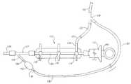
- FIG. 1is a plan view of an embodiment of the present invention adapted for use with existing catheter manifold designs
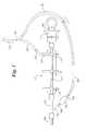
- FIG. 2is a plan view of an embodiment of the present invention integrated into a specially designed manifold
- FIG. 3is a cross-sectional view of the pump reservoir of the catheter manifold of FIG. 2;
- FIG. 4is a cross-sectional view of the pump reservoir of FIG. 3, showing the flow of contrast media upon compression;
- FIG. 5is a cross-sectional view of the pump reservoir of FIGS. 3 and 4, showing the flow of contrast media upon elastic expansion of the pump reservoir after compression ceases;
- FIG. 6is a plan view of an alternate embodiment of the present invention with a side pump
- FIG. 7is a plan view of an alternate embodiment of the fluid ejector for the pump shown in FIG. 6 .
- FIG. 1an embodiment of the present invention is shown by which the present invention may be used with a preexisting manifold preferred by the physician.
- This embodimentmay be utilized with an angiographic manifold or other appropriate catheter manifold.
- the preexisting catheter manifoldis shown generally at 110 .
- the manifoldconsists of a syringe 112 , stopcock valves 114 , 116 , and 118 , and a central lumen 120 .
- a fluid feed line 122enters the manifold at fluid line fitting 124 .
- the fluid feed line 122runs to a fluid bottle, not depicted, such as a bottle of radiographic contrast solution containing a radiopaque substance.
- the manifold 110is fitted to a suitable catheter 126 , through Y-fitting 127 .
- the embodiment of the subject inventionis fitted to the existing manifold 110 by a Y-connection or bifurcated spike 128 .
- the bifurcated spike 128is fitted to the fluid feed line 122 as well as the fluid inlet conduit 130 of this embodiment of the present invention.
- the fluid inlet conduit 130connects to an elastically compressible reservoir pump 132 . Upon compression, fluid in the compressible reservoir pump 132 is forced from the reservoir 132 into pump outlet tube 134 . Fluid is not forced from reservoir pump 132 into the fluid inlet conduit 130 , because one-way valve 136 allows fluid to flow only in the distal direction, as indicated by the arrow on the valve 136 .
- one-way valve 138has a threshold, or “cracking” pressure, required to produce flow of fluid through one-way valve 138 .
- Without a cracking pressurewhen a physician wants to take a sample of fluid from the manifold lumen 120 , the low pressure caused by the aspiration would draw fluid from reservoir 132 into manifold lumen 120 , just as it would if the reservoir 132 were compressed. This undesirable effect is prevented by the use of a one-way valve 138 with a threshold opening pressure.
- FIG. 2shows an alternate embodiment of the current invention in which the present invention is integrated into a catheter manifold, such as an angiographic manifold.
- a manifold of this embodimentis shown generally at 210 .
- the manifoldhas a syringe 212 , as well as stopcock valves 214 , 216 , and 218 .
- the manifoldhas a central lumen 220 in fluid communication with the central lumen of a catheter 222 fitted to the manifold 210 .
- a fluid feed line 224runs to a fluid bottle, which is not depicted.
- the fluid feed line 224is fitted to manifold fluid fitting 226 , and the fluid from the feed line may be introduced into manifold lumen 220 by the use of stopcock valve 214 .
- the manifold fluid fitting 226also is in fluid communication with a fluid bypass tube 228 , an embodiment of the fluid inlet conduit of the present invention.
- This fluid inlet conduit 228leads to a compressible reservoir 230 , which surrounds the distal end of the manifold 210 .
- fluid in the reservoir 230Upon compression by the physician, fluid in the reservoir 230 , such as contrast media, is forced through one-way valve 234 into manifold lumen 220 , from which point it is further delivered through catheter 222 to a distal portion of catheter 222 (not depicted). Similar to the catheter of FIG. 1, one-way valve 232 keeps fluid from flowing from the reservoir 230 back to the fluid inlet conduit 228 when the reservoir is compressed. When the reservoir 230 expands upon cessation of compression, fluid may pass from fluid inlet conduit 228 through one-way valve 232 . Fluid is not drawn from the manifold lumen 220 into reservoir 230 because one-way valve 234 prevents fluid from flowing back into the reservoir 230 . As with the catheter of FIG.
- one-way valve 234has a threshold, or ‘cracking’ pressure, to prevent fluid flow from the reservoir 230 into the manifold lumen 220 when fluids are aspirated from manifold lumen 220 .
- the compression of the reservoir 230is shown in detail in FIGS. 3 through 5.
- FIG. 3shows a cross-sectional view of an elastically compressible pump reservoir of an embodiment of the present invention, that shown in FIG. 2 .
- the reservoir 230in a preferred embodiment of the subject invention, is made of a flexible polymeric material, and may be made of a translucent material so that the existence of fluid in the reservoir may be confirmed.
- the reservoiris shown generally at 310 .
- Catheter 222is fitted to manifold 210 . Therefore, manifold lumen 220 is in fluid communication with the lumen of catheter 222 .
- the compressible reservoir 230is filled with fluid, such as radiographic contrast fluid, which has previously entered the reservoir 230 from the fluid inlet conduit 228 .
- the reservoir 230is in a stable state, and no fluid is flowing through the one-way valves 232 and 234 .
- One-way valve 234in a preferred embodiment, has a threshold pressure that is required before fluid flow will commence out of reservoir 230 and into manifold lumen 220 . This feature will tend to prevent aspiration of fluid from reservoir 230 if fluid is aspirated from manifold lumen 220 .
- FIG. 4shows the compressible reservoir 230 of FIG. 3, the reservoir 230 undergoing compression by the physician.
- the forces applied by the physicianare shown by arrows 240 and 242 . This force results in compression of the flexible reservoir 230 , as shown.
- arrow 244The flow of fluid during compression is shown by arrow 244 .
- FIG. 5shows a cross-section of the compressible reservoir 230 of FIGS. 3 and 4.
- the reservoir 230Upon cessation of compression of the elastically compressible reservoir 230 , the reservoir 230 automatically reverts to its former uncompressed shape, due to the elastomeric properties of the polymeric material used for the reservoir 230 .
- Suitable materials for the reservoir 230are silicone, rubber or other polymeric material.
- Lines 246 and 248indicate the movement of the outside walls of reservoir 230 following the release of pressure from forces 240 and 242 in FIG. 4 .
- the reduction in pressure within reservoir 230causes fluid to be sucked out of the fluid inlet conduit 228 , through one-way valve 232 .
- the fluid flowis indicated by arrow 250 . In a preferred embodiment of the present invention, no fluid moves through the one-way valve 234 .
- FIG. 6shows a plan view of an alternate embodiment of the present invention, shown generally at 610 , in which the reservoir fluid ejector 612 is adapted to project from the side of the manifold 614 .
- An elongate reservoir tube 616connects the reservoir fluid ejector 612 to the fluid inlet conduit 618 and the manifold lumen 620 .
- One-way valves 622 and 624disposed along reservoir tube 616 , prevent fluid from flowing except in the intended direction.
- the fluid ejector 612 , reservoir tube 616 , and one-way valves 622 and 624together form the pump means 632 of this embodiment of the present invention.
- Fluidis ultimately supplied from a fluid source, not depicted, such as a contrast solution bottle connected to fluid feed line 626 .
- the fluidenters the catheter through fluid feed line 626 .
- fluidis dispensed by compression of the fluid ejector 612 , forcing fluid through reservoir tube 616 , through manifold lumen 620 , and ultimately into catheter 628 and to the distal end of the catheter, not depicted.
- the fluid ejector bulb 612When the fluid ejector bulb 612 is released, it returns to its former shape, drawing fluid through one-way valve 622 .
- the bulb-type fluid ejector 612may be replaced by a spring-loaded syringe, as shown in FIG. 7 .
- debubbling valve 630is provided, which may be opened so as to allow air bubbles that might collect in the reservoir 612 or in the elongate reservoir tube 616 , either during setup of the apparatus, or during the procedure if air or other gas bubbles form or are introduced.
- the gas bubblesmay be forced out of the reservoir tube through open valve 630 , aided by compression of the reservoir 612 . This aids in preventing the introduction of gas bubbles into the vasculature of the patient, gas bubbles being an undesired effect.
- a debubbling valveis utilized by placing the debubbling valve within or in fluid communication with the pump or reservoir element of the invention, between the inlet port and outlet port of the pump element of the invention.
- FIG. 7shows a plan view of a syringe-style fluid ejector or pump of an embodiment of the present invention that may be used in place of bulb-style fluid ejector 612 in FIG. 6 .
- fluidis ejected out of the elongate reservoir tube 616 by compression of syringe plunger 618 .
- plunger 618When plunger 618 is released, it is forced back out of the syringe body 620 by compression spring 622 .
- This retraction of the syringe plunger 618creates the suction that draws fluid out of fluid inlet conduit 618 , through one-way valve 622 , not shown in FIG. 7, and into reservoir tube 616 and syringe body 620 .
Landscapes
- Health & Medical Sciences (AREA)
- Vascular Medicine (AREA)
- Engineering & Computer Science (AREA)
- Anesthesiology (AREA)
- Biomedical Technology (AREA)
- Heart & Thoracic Surgery (AREA)
- Hematology (AREA)
- Life Sciences & Earth Sciences (AREA)
- Animal Behavior & Ethology (AREA)
- General Health & Medical Sciences (AREA)
- Public Health (AREA)
- Veterinary Medicine (AREA)
- Infusion, Injection, And Reservoir Apparatuses (AREA)
Abstract
Description
Claims (36)
Priority Applications (6)
| Application Number | Priority Date | Filing Date | Title |
|---|---|---|---|
| US09/739,403US6520937B2 (en) | 2000-12-18 | 2000-12-18 | Fluid injection device |
| EP01977778AEP1345645A1 (en) | 2000-12-18 | 2001-09-13 | Fluid injection device |
| JP2002551037AJP2004528058A (en) | 2000-12-18 | 2001-09-13 | Fluid injection device |
| AU2001296870AAU2001296870A1 (en) | 2000-12-18 | 2001-09-13 | Fluid injection device |
| CA002431757ACA2431757A1 (en) | 2000-12-18 | 2001-09-13 | Fluid injection device |
| PCT/US2001/042122WO2002049700A1 (en) | 2000-12-18 | 2001-09-13 | Fluid injection device |
Applications Claiming Priority (1)
| Application Number | Priority Date | Filing Date | Title |
|---|---|---|---|
| US09/739,403US6520937B2 (en) | 2000-12-18 | 2000-12-18 | Fluid injection device |
Publications (2)
| Publication Number | Publication Date |
|---|---|
| US20020077597A1 US20020077597A1 (en) | 2002-06-20 |
| US6520937B2true US6520937B2 (en) | 2003-02-18 |
Family
ID=24972127
Family Applications (1)
| Application Number | Title | Priority Date | Filing Date |
|---|---|---|---|
| US09/739,403Expired - Fee RelatedUS6520937B2 (en) | 2000-12-18 | 2000-12-18 | Fluid injection device |
Country Status (6)
| Country | Link |
|---|---|
| US (1) | US6520937B2 (en) |
| EP (1) | EP1345645A1 (en) |
| JP (1) | JP2004528058A (en) |
| AU (1) | AU2001296870A1 (en) |
| CA (1) | CA2431757A1 (en) |
| WO (1) | WO2002049700A1 (en) |
Cited By (48)
| Publication number | Priority date | Publication date | Assignee | Title |
|---|---|---|---|---|
| US20040221904A1 (en)* | 2003-05-06 | 2004-11-11 | Usher Kathryn Mary | Fluid manifold control device |
| US20060186143A1 (en)* | 2005-02-24 | 2006-08-24 | Boston Scientific Santa Rosa Corporation | Constant force material delivery system and method |
| US20070069406A1 (en)* | 2005-08-23 | 2007-03-29 | General Electric Company | Tool for transferring controlled amounts of fluid into and from a fluid flow circuit |
| US20070233051A1 (en)* | 2006-03-31 | 2007-10-04 | David Hohl | Drug delivery systems and methods |
| US20070235331A1 (en)* | 2003-07-25 | 2007-10-11 | Dexcom, Inc. | Analyte sensors having a signal-to-noise ratio substantially unaffected by non-constant noise |
| US20070244379A1 (en)* | 2002-05-22 | 2007-10-18 | Robert Boock | Silicone based membranes for use in implantable glucose sensors |
| US20080015505A1 (en)* | 2001-07-10 | 2008-01-17 | Medrad, Inc. | Infusion pump system for use in mri suites |
| US20080194938A1 (en)* | 2004-07-13 | 2008-08-14 | Dexcom, Inc. | Transcutaneous medical device with variable stiffness |
| US20080197024A1 (en)* | 2003-12-05 | 2008-08-21 | Dexcom, Inc. | Analyte sensor |
| US20090090921A1 (en)* | 2006-08-29 | 2009-04-09 | Samsung Electro-Mechanics Co., Ltd. | Nitride semiconductor light emitting diode |
| US20090124964A1 (en)* | 2003-12-05 | 2009-05-14 | Dexcom, Inc. | Integrated device for continuous in vivo analyte detection and simultaneous control of an infusion device |
| US20090131777A1 (en)* | 2006-10-04 | 2009-05-21 | Dexcom, Inc. | Analyte sensor |
| US20090131768A1 (en)* | 2006-10-04 | 2009-05-21 | Dexcom, Inc. | Analyte sensor |
| US20090131776A1 (en)* | 2006-10-04 | 2009-05-21 | Dexcom, Inc. | Analyte sensor |
| US20090131769A1 (en)* | 2006-10-04 | 2009-05-21 | Dexcom, Inc. | Analyte sensor |
| US20090137887A1 (en)* | 2006-10-04 | 2009-05-28 | Dexcom, Inc. | Analyte sensor |
| US20090157004A1 (en)* | 2004-10-12 | 2009-06-18 | Iradimed Corporation | Non-magnetic medical infusion device |
| US20090156924A1 (en)* | 2007-12-17 | 2009-06-18 | Dexcom, Inc. | Systems and methods for processing sensor data |
| US20090182217A1 (en)* | 2003-12-05 | 2009-07-16 | Dexcom, Inc. | Analyte sensor |
| US20090178459A1 (en)* | 2003-08-01 | 2009-07-16 | Dexcom, Inc. | Analyte sensor |
| US20090204078A1 (en)* | 2008-02-13 | 2009-08-13 | Boston Scientific Scimed, Inc. | Manifold and Valve Seal for Use with a Medical Device |
| US20090242425A1 (en)* | 2008-03-25 | 2009-10-01 | Dexcom, Inc. | Analyte sensor |
| US7615007B2 (en) | 2006-10-04 | 2009-11-10 | Dexcom, Inc. | Analyte sensor |
| US7640048B2 (en) | 2004-07-13 | 2009-12-29 | Dexcom, Inc. | Analyte sensor |
| US8364231B2 (en) | 2006-10-04 | 2013-01-29 | Dexcom, Inc. | Analyte sensor |
| US8364230B2 (en) | 2006-10-04 | 2013-01-29 | Dexcom, Inc. | Analyte sensor |
| US8425416B2 (en) | 2006-10-04 | 2013-04-23 | Dexcom, Inc. | Analyte sensor |
| US8447376B2 (en) | 2006-10-04 | 2013-05-21 | Dexcom, Inc. | Analyte sensor |
| US8562558B2 (en) | 2007-06-08 | 2013-10-22 | Dexcom, Inc. | Integrated medicament delivery device for use with continuous analyte sensor |
| US8886273B2 (en) | 2003-08-01 | 2014-11-11 | Dexcom, Inc. | Analyte sensor |
| US9135402B2 (en) | 2007-12-17 | 2015-09-15 | Dexcom, Inc. | Systems and methods for processing sensor data |
| US9763609B2 (en) | 2003-07-25 | 2017-09-19 | Dexcom, Inc. | Analyte sensors having a signal-to-noise ratio substantially unaffected by non-constant noise |
| US9956377B2 (en) | 2002-09-20 | 2018-05-01 | Angiodynamics, Inc. | Method and apparatus for intra-aortic substance delivery to a branch vessel |
| US10279112B2 (en) | 2012-09-24 | 2019-05-07 | Angiodynamics, Inc. | Power injector device and method of use |
| US10524703B2 (en) | 2004-07-13 | 2020-01-07 | Dexcom, Inc. | Transcutaneous analyte sensor |
| US10610135B2 (en) | 2005-03-10 | 2020-04-07 | Dexcom, Inc. | System and methods for processing analyte sensor data for sensor calibration |
| US10791928B2 (en) | 2007-05-18 | 2020-10-06 | Dexcom, Inc. | Analyte sensors having a signal-to-noise ratio substantially unaffected by non-constant noise |
| US10813577B2 (en) | 2005-06-21 | 2020-10-27 | Dexcom, Inc. | Analyte sensor |
| US10835672B2 (en) | 2004-02-26 | 2020-11-17 | Dexcom, Inc. | Integrated insulin delivery system with continuous glucose sensor |
| US10966609B2 (en) | 2004-02-26 | 2021-04-06 | Dexcom, Inc. | Integrated medicament delivery device for use with continuous analyte sensor |
| US10980461B2 (en) | 2008-11-07 | 2021-04-20 | Dexcom, Inc. | Advanced analyte sensor calibration and error detection |
| US11000215B1 (en) | 2003-12-05 | 2021-05-11 | Dexcom, Inc. | Analyte sensor |
| US11246990B2 (en) | 2004-02-26 | 2022-02-15 | Dexcom, Inc. | Integrated delivery device for continuous glucose sensor |
| US11331022B2 (en) | 2017-10-24 | 2022-05-17 | Dexcom, Inc. | Pre-connected analyte sensors |
| US11350862B2 (en) | 2017-10-24 | 2022-06-07 | Dexcom, Inc. | Pre-connected analyte sensors |
| US11369739B2 (en) | 2013-01-21 | 2022-06-28 | Medline Industries, Lp | Method to provide injection system parameters for injecting fluid into patient |
| US11399745B2 (en) | 2006-10-04 | 2022-08-02 | Dexcom, Inc. | Dual electrode system for a continuous analyte sensor |
| US11633133B2 (en) | 2003-12-05 | 2023-04-25 | Dexcom, Inc. | Dual electrode system for a continuous analyte sensor |
Families Citing this family (3)
| Publication number | Priority date | Publication date | Assignee | Title |
|---|---|---|---|---|
| US9616167B2 (en) | 2011-05-24 | 2017-04-11 | Boston Scientific Scimed, Inc. | Anesthetic delivery device |
| US11577024B2 (en)* | 2019-05-09 | 2023-02-14 | Bohnas Innovations LLC | Dual lumen IV administration set |
| CN115068731B (en)* | 2022-08-08 | 2023-04-21 | 河南中医药大学第一附属医院 | Contrast agent delivery puncturing device for breast catheter imaging and method of using same |
Citations (41)
| Publication number | Priority date | Publication date | Assignee | Title |
|---|---|---|---|---|
| US2866457A (en) | 1956-12-20 | 1958-12-30 | Cutter Lab | Apparatus for administration of parenteral fluids |
| US2999499A (en) | 1958-07-11 | 1961-09-12 | Cutter Lab | Flexible check valve |
| US3001525A (en) | 1957-11-05 | 1961-09-26 | American Sterilizer Co | Parenteral equipment |
| US3057350A (en) | 1958-06-27 | 1962-10-09 | Baxter Don Inc | Administration set |
| US3211150A (en) | 1963-08-15 | 1965-10-12 | Foderick John Walter | Balloon catheter with integral valves controlling inflation |
| US3533400A (en) | 1967-04-05 | 1970-10-13 | William E Palich | Continuous reading venous manometer for injecting parenteral fluids |
| US3776229A (en) | 1971-11-26 | 1973-12-04 | American Hospital Supply Corp | Medical liquid administration set for rate or volume delivery |
| US3951145A (en) | 1973-10-25 | 1976-04-20 | Bob Lee Smith | Intravenous measuring chamber |
| US4038983A (en) | 1976-01-26 | 1977-08-02 | Baxter Travenol Laboratories, Inc. | Fluid infusion pump |
| US4078563A (en) | 1976-06-10 | 1978-03-14 | Cutter Laboratories, Inc. | Disc valve in a container for dispensing liquids |
| US4175558A (en) | 1977-07-15 | 1979-11-27 | Baxter Travenol Laboratories, Inc. | Apparatus for administering parenteral liquid in sequential units provided with a ball valve float |
| US4325368A (en) | 1978-12-16 | 1982-04-20 | Ingrid Bernard | Infusion device |
| US4425123A (en) | 1980-12-30 | 1984-01-10 | Sis-Ter S.P.A. | Parenteral liquid application apparatus |
| US4428383A (en) | 1981-10-13 | 1984-01-31 | American Hospital Supply Corporation | Manifold for monitoring hemodynamic pressure |
| US4534757A (en) | 1982-06-14 | 1985-08-13 | Alza Corporation | Device for releasing active ingredient, insertable in a system of parenteral administering the ingredient |
| US4548598A (en) | 1981-10-09 | 1985-10-22 | Alza Corporation | Parenteral agent dispensing equipment |
| US4734091A (en) | 1985-02-11 | 1988-03-29 | Atlantic Optical Systems, Inc. | Filtered manifold apparatus and method for ophthalmic irrigation |
| US4750643A (en) | 1986-08-04 | 1988-06-14 | Sugrin Surgical Instrumentation, Inc. | Sterile fluid dispensing system and method |
| US4858619A (en) | 1987-06-29 | 1989-08-22 | Toth Marie A | Intracranial pressure monitoring system |
| US4869457A (en) | 1986-09-10 | 1989-09-26 | Ewerloef Goeran | Arrangement for controlling and regulating a liquid flowing through a line |
| US4892524A (en) | 1987-10-30 | 1990-01-09 | Gordon Smith | Intravenous administration system |
| US4976685A (en) | 1988-06-15 | 1990-12-11 | Block Jr Frank E | Method of blood-gas interface control in surgical gas traps |
| EP0413069A1 (en) | 1989-08-15 | 1991-02-20 | Imed Corporation | Dual chamber pumping apparatus |
| US5059173A (en) | 1990-04-04 | 1991-10-22 | Sacco John J | IV apparatus |
| US5074334A (en) | 1989-07-27 | 1991-12-24 | Terumo Kabushiki Kaisha | Multi-way cock |
| US5078688A (en) | 1989-09-22 | 1992-01-07 | Baxter International Inc. | Paracentesis catheter system |
| US5084031A (en) | 1989-09-12 | 1992-01-28 | Research Medical, Inc. | Cardioplegia three-way double stopcock |
| US5135026A (en) | 1989-08-16 | 1992-08-04 | Manska Wayne E | Medical valve having fluid flow indicia |
| US5167643A (en) | 1990-04-27 | 1992-12-01 | Lynn Lawrence A | Needle protection station |
| US5238026A (en) | 1989-11-14 | 1993-08-24 | Chisso Corporation | Liquid outflow control unit |
| US5334170A (en)* | 1993-07-14 | 1994-08-02 | Abbott Laboratories | Dye management system including an administration set with an in-line burette |
| US5356375A (en)* | 1992-04-06 | 1994-10-18 | Namic U.S.A. Corporation | Positive pressure fluid delivery and waste removal system |
| US5423751A (en) | 1993-02-18 | 1995-06-13 | Harrison; Samuel W. | Contrast media dispensing apparatus |
| US5533978A (en) | 1994-11-07 | 1996-07-09 | Teirstein; Paul S. | Method and apparatus for uninterrupted delivery of radiographic dye |
| US5569208A (en)* | 1995-08-01 | 1996-10-29 | Merit Medical Systems, Inc. | System for managing delivery of contrast media |
| US5593385A (en) | 1993-02-18 | 1997-01-14 | Harrison; Samuel W. | Contrast media dispensing apparatus |
| US5665074A (en) | 1995-09-28 | 1997-09-09 | Liebel Flarsheim Company | Limited backflow reflux valve |
| US5807321A (en)* | 1995-11-28 | 1998-09-15 | Merit Medical | System for electronically monitoring the delivery of contrast media |
| US6056727A (en) | 1991-07-01 | 2000-05-02 | O'neil; Alexander George Brian | Apparatus for patient-controlled infusion |
| US6063052A (en) | 1993-10-28 | 2000-05-16 | Medrad, Inc. | Injection system and pumping system for use therein |
| US6371942B1 (en)* | 1998-09-23 | 2002-04-16 | Mayo Foundation For Medical Education And Research | Automatic manifold for vascular catheter |
- 2000
- 2000-12-18USUS09/739,403patent/US6520937B2/ennot_activeExpired - Fee Related
- 2001
- 2001-09-13CACA002431757Apatent/CA2431757A1/ennot_activeAbandoned
- 2001-09-13WOPCT/US2001/042122patent/WO2002049700A1/ennot_activeApplication Discontinuation
- 2001-09-13JPJP2002551037Apatent/JP2004528058A/enactivePending
- 2001-09-13EPEP01977778Apatent/EP1345645A1/ennot_activeWithdrawn
- 2001-09-13AUAU2001296870Apatent/AU2001296870A1/ennot_activeAbandoned
Patent Citations (44)
| Publication number | Priority date | Publication date | Assignee | Title |
|---|---|---|---|---|
| US2866457A (en) | 1956-12-20 | 1958-12-30 | Cutter Lab | Apparatus for administration of parenteral fluids |
| US3001525A (en) | 1957-11-05 | 1961-09-26 | American Sterilizer Co | Parenteral equipment |
| US3057350A (en) | 1958-06-27 | 1962-10-09 | Baxter Don Inc | Administration set |
| US2999499A (en) | 1958-07-11 | 1961-09-12 | Cutter Lab | Flexible check valve |
| US3211150A (en) | 1963-08-15 | 1965-10-12 | Foderick John Walter | Balloon catheter with integral valves controlling inflation |
| US3533400A (en) | 1967-04-05 | 1970-10-13 | William E Palich | Continuous reading venous manometer for injecting parenteral fluids |
| US3776229A (en) | 1971-11-26 | 1973-12-04 | American Hospital Supply Corp | Medical liquid administration set for rate or volume delivery |
| US3951145A (en) | 1973-10-25 | 1976-04-20 | Bob Lee Smith | Intravenous measuring chamber |
| US4038983A (en) | 1976-01-26 | 1977-08-02 | Baxter Travenol Laboratories, Inc. | Fluid infusion pump |
| US4078563A (en) | 1976-06-10 | 1978-03-14 | Cutter Laboratories, Inc. | Disc valve in a container for dispensing liquids |
| US4175558A (en) | 1977-07-15 | 1979-11-27 | Baxter Travenol Laboratories, Inc. | Apparatus for administering parenteral liquid in sequential units provided with a ball valve float |
| US4325368A (en) | 1978-12-16 | 1982-04-20 | Ingrid Bernard | Infusion device |
| US4425123A (en) | 1980-12-30 | 1984-01-10 | Sis-Ter S.P.A. | Parenteral liquid application apparatus |
| US4548598A (en) | 1981-10-09 | 1985-10-22 | Alza Corporation | Parenteral agent dispensing equipment |
| US4428383A (en) | 1981-10-13 | 1984-01-31 | American Hospital Supply Corporation | Manifold for monitoring hemodynamic pressure |
| US4534757A (en) | 1982-06-14 | 1985-08-13 | Alza Corporation | Device for releasing active ingredient, insertable in a system of parenteral administering the ingredient |
| US4734091A (en) | 1985-02-11 | 1988-03-29 | Atlantic Optical Systems, Inc. | Filtered manifold apparatus and method for ophthalmic irrigation |
| US4750643A (en) | 1986-08-04 | 1988-06-14 | Sugrin Surgical Instrumentation, Inc. | Sterile fluid dispensing system and method |
| US4869457A (en) | 1986-09-10 | 1989-09-26 | Ewerloef Goeran | Arrangement for controlling and regulating a liquid flowing through a line |
| US4858619A (en) | 1987-06-29 | 1989-08-22 | Toth Marie A | Intracranial pressure monitoring system |
| US4892524A (en) | 1987-10-30 | 1990-01-09 | Gordon Smith | Intravenous administration system |
| US4976685A (en) | 1988-06-15 | 1990-12-11 | Block Jr Frank E | Method of blood-gas interface control in surgical gas traps |
| US5074334A (en) | 1989-07-27 | 1991-12-24 | Terumo Kabushiki Kaisha | Multi-way cock |
| EP0413069A1 (en) | 1989-08-15 | 1991-02-20 | Imed Corporation | Dual chamber pumping apparatus |
| US5135026A (en) | 1989-08-16 | 1992-08-04 | Manska Wayne E | Medical valve having fluid flow indicia |
| US5084031A (en) | 1989-09-12 | 1992-01-28 | Research Medical, Inc. | Cardioplegia three-way double stopcock |
| US5078688A (en) | 1989-09-22 | 1992-01-07 | Baxter International Inc. | Paracentesis catheter system |
| US5238026A (en) | 1989-11-14 | 1993-08-24 | Chisso Corporation | Liquid outflow control unit |
| US5059173A (en) | 1990-04-04 | 1991-10-22 | Sacco John J | IV apparatus |
| US5167643A (en) | 1990-04-27 | 1992-12-01 | Lynn Lawrence A | Needle protection station |
| US6056727A (en) | 1991-07-01 | 2000-05-02 | O'neil; Alexander George Brian | Apparatus for patient-controlled infusion |
| US5356375A (en)* | 1992-04-06 | 1994-10-18 | Namic U.S.A. Corporation | Positive pressure fluid delivery and waste removal system |
| US5423751A (en) | 1993-02-18 | 1995-06-13 | Harrison; Samuel W. | Contrast media dispensing apparatus |
| US5593385A (en) | 1993-02-18 | 1997-01-14 | Harrison; Samuel W. | Contrast media dispensing apparatus |
| US5334170A (en)* | 1993-07-14 | 1994-08-02 | Abbott Laboratories | Dye management system including an administration set with an in-line burette |
| US6063052A (en) | 1993-10-28 | 2000-05-16 | Medrad, Inc. | Injection system and pumping system for use therein |
| US5533978A (en) | 1994-11-07 | 1996-07-09 | Teirstein; Paul S. | Method and apparatus for uninterrupted delivery of radiographic dye |
| US5911708A (en) | 1994-11-07 | 1999-06-15 | Teirstein; Paul S. | Method and apparatus for uninterrupted delivery of radiographic dye |
| US5779666A (en)* | 1994-11-07 | 1998-07-14 | Teirstein; Paul S. | Method and apparatus for uninterrupted delivery of radiographic dye |
| US5569208A (en)* | 1995-08-01 | 1996-10-29 | Merit Medical Systems, Inc. | System for managing delivery of contrast media |
| US5743872A (en) | 1995-09-28 | 1998-04-28 | Liebel-Flarsheim Company | Limited backflow reflux valve and method |
| US5665074A (en) | 1995-09-28 | 1997-09-09 | Liebel Flarsheim Company | Limited backflow reflux valve |
| US5807321A (en)* | 1995-11-28 | 1998-09-15 | Merit Medical | System for electronically monitoring the delivery of contrast media |
| US6371942B1 (en)* | 1998-09-23 | 2002-04-16 | Mayo Foundation For Medical Education And Research | Automatic manifold for vascular catheter |
Cited By (149)
| Publication number | Priority date | Publication date | Assignee | Title |
|---|---|---|---|---|
| US20080015505A1 (en)* | 2001-07-10 | 2008-01-17 | Medrad, Inc. | Infusion pump system for use in mri suites |
| US9549693B2 (en) | 2002-05-22 | 2017-01-24 | Dexcom, Inc. | Silicone based membranes for use in implantable glucose sensors |
| US11020026B2 (en) | 2002-05-22 | 2021-06-01 | Dexcom, Inc. | Silicone based membranes for use in implantable glucose sensors |
| US10052051B2 (en) | 2002-05-22 | 2018-08-21 | Dexcom, Inc. | Silicone based membranes for use in implantable glucose sensors |
| US20070244379A1 (en)* | 2002-05-22 | 2007-10-18 | Robert Boock | Silicone based membranes for use in implantable glucose sensors |
| US8064977B2 (en) | 2002-05-22 | 2011-11-22 | Dexcom, Inc. | Silicone based membranes for use in implantable glucose sensors |
| US8543184B2 (en) | 2002-05-22 | 2013-09-24 | Dexcom, Inc. | Silicone based membranes for use in implantable glucose sensors |
| US7613491B2 (en) | 2002-05-22 | 2009-11-03 | Dexcom, Inc. | Silicone based membranes for use in implantable glucose sensors |
| US9956377B2 (en) | 2002-09-20 | 2018-05-01 | Angiodynamics, Inc. | Method and apparatus for intra-aortic substance delivery to a branch vessel |
| US20090198209A1 (en)* | 2003-05-06 | 2009-08-06 | Kathryn Mary Usher | Fluid manifold control device |
| US7513890B2 (en) | 2003-05-06 | 2009-04-07 | Navilyst Medical, Inc. | Fluid manifold control device |
| US20040221904A1 (en)* | 2003-05-06 | 2004-11-11 | Usher Kathryn Mary | Fluid manifold control device |
| US8364229B2 (en) | 2003-07-25 | 2013-01-29 | Dexcom, Inc. | Analyte sensors having a signal-to-noise ratio substantially unaffected by non-constant noise |
| US20070235331A1 (en)* | 2003-07-25 | 2007-10-11 | Dexcom, Inc. | Analyte sensors having a signal-to-noise ratio substantially unaffected by non-constant noise |
| US9763609B2 (en) | 2003-07-25 | 2017-09-19 | Dexcom, Inc. | Analyte sensors having a signal-to-noise ratio substantially unaffected by non-constant noise |
| US10376143B2 (en) | 2003-07-25 | 2019-08-13 | Dexcom, Inc. | Analyte sensors having a signal-to-noise ratio substantially unaffected by non-constant noise |
| US8886273B2 (en) | 2003-08-01 | 2014-11-11 | Dexcom, Inc. | Analyte sensor |
| US10052055B2 (en) | 2003-08-01 | 2018-08-21 | Dexcom, Inc. | Analyte sensor |
| US20090178459A1 (en)* | 2003-08-01 | 2009-07-16 | Dexcom, Inc. | Analyte sensor |
| US8626257B2 (en) | 2003-08-01 | 2014-01-07 | Dexcom, Inc. | Analyte sensor |
| US20080197024A1 (en)* | 2003-12-05 | 2008-08-21 | Dexcom, Inc. | Analyte sensor |
| US11633133B2 (en) | 2003-12-05 | 2023-04-25 | Dexcom, Inc. | Dual electrode system for a continuous analyte sensor |
| US8287453B2 (en) | 2003-12-05 | 2012-10-16 | Dexcom, Inc. | Analyte sensor |
| US8425417B2 (en) | 2003-12-05 | 2013-04-23 | Dexcom, Inc. | Integrated device for continuous in vivo analyte detection and simultaneous control of an infusion device |
| US11000215B1 (en) | 2003-12-05 | 2021-05-11 | Dexcom, Inc. | Analyte sensor |
| US11020031B1 (en) | 2003-12-05 | 2021-06-01 | Dexcom, Inc. | Analyte sensor |
| US20090124964A1 (en)* | 2003-12-05 | 2009-05-14 | Dexcom, Inc. | Integrated device for continuous in vivo analyte detection and simultaneous control of an infusion device |
| US20090182217A1 (en)* | 2003-12-05 | 2009-07-16 | Dexcom, Inc. | Analyte sensor |
| US11246990B2 (en) | 2004-02-26 | 2022-02-15 | Dexcom, Inc. | Integrated delivery device for continuous glucose sensor |
| US12102410B2 (en) | 2004-02-26 | 2024-10-01 | Dexcom, Inc | Integrated medicament delivery device for use with continuous analyte sensor |
| US12115357B2 (en) | 2004-02-26 | 2024-10-15 | Dexcom, Inc. | Integrated delivery device for continuous glucose sensor |
| US10966609B2 (en) | 2004-02-26 | 2021-04-06 | Dexcom, Inc. | Integrated medicament delivery device for use with continuous analyte sensor |
| US12226617B2 (en) | 2004-02-26 | 2025-02-18 | Dexcom, Inc. | Integrated delivery device for continuous glucose sensor |
| US10835672B2 (en) | 2004-02-26 | 2020-11-17 | Dexcom, Inc. | Integrated insulin delivery system with continuous glucose sensor |
| US10980452B2 (en) | 2004-07-13 | 2021-04-20 | Dexcom, Inc. | Analyte sensor |
| US10918314B2 (en) | 2004-07-13 | 2021-02-16 | Dexcom, Inc. | Analyte sensor |
| US10709362B2 (en) | 2004-07-13 | 2020-07-14 | Dexcom, Inc. | Analyte sensor |
| US10709363B2 (en) | 2004-07-13 | 2020-07-14 | Dexcom, Inc. | Analyte sensor |
| US10722152B2 (en) | 2004-07-13 | 2020-07-28 | Dexcom, Inc. | Analyte sensor |
| US11883164B2 (en) | 2004-07-13 | 2024-01-30 | Dexcom, Inc. | System and methods for processing analyte sensor data for sensor calibration |
| US7783333B2 (en) | 2004-07-13 | 2010-08-24 | Dexcom, Inc. | Transcutaneous medical device with variable stiffness |
| US20080194938A1 (en)* | 2004-07-13 | 2008-08-14 | Dexcom, Inc. | Transcutaneous medical device with variable stiffness |
| US11064917B2 (en) | 2004-07-13 | 2021-07-20 | Dexcom, Inc. | Analyte sensor |
| US11045120B2 (en) | 2004-07-13 | 2021-06-29 | Dexcom, Inc. | Analyte sensor |
| US11026605B1 (en) | 2004-07-13 | 2021-06-08 | Dexcom, Inc. | Analyte sensor |
| US10993641B2 (en) | 2004-07-13 | 2021-05-04 | Dexcom, Inc. | Analyte sensor |
| US10993642B2 (en) | 2004-07-13 | 2021-05-04 | Dexcom, Inc. | Analyte sensor |
| US7857760B2 (en) | 2004-07-13 | 2010-12-28 | Dexcom, Inc. | Analyte sensor |
| US10932700B2 (en) | 2004-07-13 | 2021-03-02 | Dexcom, Inc. | Analyte sensor |
| US10524703B2 (en) | 2004-07-13 | 2020-01-07 | Dexcom, Inc. | Transcutaneous analyte sensor |
| US10918313B2 (en) | 2004-07-13 | 2021-02-16 | Dexcom, Inc. | Analyte sensor |
| US10918315B2 (en) | 2004-07-13 | 2021-02-16 | Dexcom, Inc. | Analyte sensor |
| US7640048B2 (en) | 2004-07-13 | 2009-12-29 | Dexcom, Inc. | Analyte sensor |
| US8812072B2 (en) | 2004-07-13 | 2014-08-19 | Dexcom, Inc. | Transcutaneous medical device with variable stiffness |
| US10827956B2 (en) | 2004-07-13 | 2020-11-10 | Dexcom, Inc. | Analyte sensor |
| US10813576B2 (en) | 2004-07-13 | 2020-10-27 | Dexcom, Inc. | Analyte sensor |
| US10799159B2 (en) | 2004-07-13 | 2020-10-13 | Dexcom, Inc. | Analyte sensor |
| US8750955B2 (en) | 2004-07-13 | 2014-06-10 | Dexcom, Inc. | Analyte sensor |
| US10799158B2 (en) | 2004-07-13 | 2020-10-13 | Dexcom, Inc. | Analyte sensor |
| US20090157004A1 (en)* | 2004-10-12 | 2009-06-18 | Iradimed Corporation | Non-magnetic medical infusion device |
| US8262642B2 (en)* | 2004-10-12 | 2012-09-11 | Iradimed Corporation | IV fluid infusion assembly |
| US7708163B2 (en) | 2005-02-24 | 2010-05-04 | Trivascular2, Inc. | Constant force material delivery system and method |
| US20100170919A1 (en)* | 2005-02-24 | 2010-07-08 | Trivascular2, Inc. | Constant force material delivery system and method |
| US20060186143A1 (en)* | 2005-02-24 | 2006-08-24 | Boston Scientific Santa Rosa Corporation | Constant force material delivery system and method |
| US7971751B2 (en)* | 2005-02-24 | 2011-07-05 | Trivascular, Inc. | Constant force material delivery system and method |
| US10743801B2 (en) | 2005-03-10 | 2020-08-18 | Dexcom, Inc. | System and methods for processing analyte sensor data for sensor calibration |
| US10856787B2 (en) | 2005-03-10 | 2020-12-08 | Dexcom, Inc. | System and methods for processing analyte sensor data for sensor calibration |
| US10610137B2 (en) | 2005-03-10 | 2020-04-07 | Dexcom, Inc. | System and methods for processing analyte sensor data for sensor calibration |
| US10610136B2 (en) | 2005-03-10 | 2020-04-07 | Dexcom, Inc. | System and methods for processing analyte sensor data for sensor calibration |
| US10610135B2 (en) | 2005-03-10 | 2020-04-07 | Dexcom, Inc. | System and methods for processing analyte sensor data for sensor calibration |
| US11051726B2 (en) | 2005-03-10 | 2021-07-06 | Dexcom, Inc. | System and methods for processing analyte sensor data for sensor calibration |
| US11000213B2 (en) | 2005-03-10 | 2021-05-11 | Dexcom, Inc. | System and methods for processing analyte sensor data for sensor calibration |
| US10925524B2 (en) | 2005-03-10 | 2021-02-23 | Dexcom, Inc. | System and methods for processing analyte sensor data for sensor calibration |
| US10918318B2 (en) | 2005-03-10 | 2021-02-16 | Dexcom, Inc. | System and methods for processing analyte sensor data for sensor calibration |
| US10709364B2 (en) | 2005-03-10 | 2020-07-14 | Dexcom, Inc. | System and methods for processing analyte sensor data for sensor calibration |
| US10918317B2 (en) | 2005-03-10 | 2021-02-16 | Dexcom, Inc. | System and methods for processing analyte sensor data for sensor calibration |
| US10918316B2 (en) | 2005-03-10 | 2021-02-16 | Dexcom, Inc. | System and methods for processing analyte sensor data for sensor calibration |
| US10898114B2 (en) | 2005-03-10 | 2021-01-26 | Dexcom, Inc. | System and methods for processing analyte sensor data for sensor calibration |
| US10617336B2 (en) | 2005-03-10 | 2020-04-14 | Dexcom, Inc. | System and methods for processing analyte sensor data for sensor calibration |
| US10716498B2 (en) | 2005-03-10 | 2020-07-21 | Dexcom, Inc. | System and methods for processing analyte sensor data for sensor calibration |
| US10813577B2 (en) | 2005-06-21 | 2020-10-27 | Dexcom, Inc. | Analyte sensor |
| US7571750B2 (en) | 2005-08-23 | 2009-08-11 | General Electric Co. | Tool for transferring controlled amounts of fluid into and from a fluid flow circuit |
| US20070069406A1 (en)* | 2005-08-23 | 2007-03-29 | General Electric Company | Tool for transferring controlled amounts of fluid into and from a fluid flow circuit |
| US20070233051A1 (en)* | 2006-03-31 | 2007-10-04 | David Hohl | Drug delivery systems and methods |
| US20090090921A1 (en)* | 2006-08-29 | 2009-04-09 | Samsung Electro-Mechanics Co., Ltd. | Nitride semiconductor light emitting diode |
| US8449464B2 (en) | 2006-10-04 | 2013-05-28 | Dexcom, Inc. | Analyte sensor |
| US11399745B2 (en) | 2006-10-04 | 2022-08-02 | Dexcom, Inc. | Dual electrode system for a continuous analyte sensor |
| US20100298684A1 (en)* | 2006-10-04 | 2010-11-25 | Dexcom, Inc. | Analyte sensor |
| US20090287074A1 (en)* | 2006-10-04 | 2009-11-19 | Dexcom, Inc. | Analyte sensor |
| US8275438B2 (en) | 2006-10-04 | 2012-09-25 | Dexcom, Inc. | Analyte sensor |
| US11382539B2 (en) | 2006-10-04 | 2022-07-12 | Dexcom, Inc. | Analyte sensor |
| US8911367B2 (en) | 2006-10-04 | 2014-12-16 | Dexcom, Inc. | Analyte sensor |
| US7615007B2 (en) | 2006-10-04 | 2009-11-10 | Dexcom, Inc. | Analyte sensor |
| US8774886B2 (en) | 2006-10-04 | 2014-07-08 | Dexcom, Inc. | Analyte sensor |
| US20100081910A1 (en)* | 2006-10-04 | 2010-04-01 | Dexcom, Inc. | Analyte sensor |
| US8298142B2 (en) | 2006-10-04 | 2012-10-30 | Dexcom, Inc. | Analyte sensor |
| US8562528B2 (en) | 2006-10-04 | 2013-10-22 | Dexcom, Inc. | Analyte sensor |
| US8364231B2 (en) | 2006-10-04 | 2013-01-29 | Dexcom, Inc. | Analyte sensor |
| US7775975B2 (en) | 2006-10-04 | 2010-08-17 | Dexcom, Inc. | Analyte sensor |
| US8532730B2 (en) | 2006-10-04 | 2013-09-10 | Dexcom, Inc. | Analyte sensor |
| US20090131777A1 (en)* | 2006-10-04 | 2009-05-21 | Dexcom, Inc. | Analyte sensor |
| US20090131768A1 (en)* | 2006-10-04 | 2009-05-21 | Dexcom, Inc. | Analyte sensor |
| US10349873B2 (en) | 2006-10-04 | 2019-07-16 | Dexcom, Inc. | Analyte sensor |
| US20090131776A1 (en)* | 2006-10-04 | 2009-05-21 | Dexcom, Inc. | Analyte sensor |
| US8478377B2 (en) | 2006-10-04 | 2013-07-02 | Dexcom, Inc. | Analyte sensor |
| US9451908B2 (en) | 2006-10-04 | 2016-09-27 | Dexcom, Inc. | Analyte sensor |
| US8364230B2 (en) | 2006-10-04 | 2013-01-29 | Dexcom, Inc. | Analyte sensor |
| US8447376B2 (en) | 2006-10-04 | 2013-05-21 | Dexcom, Inc. | Analyte sensor |
| US20090131769A1 (en)* | 2006-10-04 | 2009-05-21 | Dexcom, Inc. | Analyte sensor |
| US8425416B2 (en) | 2006-10-04 | 2013-04-23 | Dexcom, Inc. | Analyte sensor |
| US20090137887A1 (en)* | 2006-10-04 | 2009-05-28 | Dexcom, Inc. | Analyte sensor |
| US10791928B2 (en) | 2007-05-18 | 2020-10-06 | Dexcom, Inc. | Analyte sensors having a signal-to-noise ratio substantially unaffected by non-constant noise |
| US12433485B2 (en) | 2007-05-18 | 2025-10-07 | Dexcom, Inc. | Analyte sensors having a signal-to-noise ratio substantially unaffected by non-constant noise |
| US11373347B2 (en) | 2007-06-08 | 2022-06-28 | Dexcom, Inc. | Integrated medicament delivery device for use with continuous analyte sensor |
| US9741139B2 (en) | 2007-06-08 | 2017-08-22 | Dexcom, Inc. | Integrated medicament delivery device for use with continuous analyte sensor |
| US10403012B2 (en) | 2007-06-08 | 2019-09-03 | Dexcom, Inc. | Integrated medicament delivery device for use with continuous analyte sensor |
| US8562558B2 (en) | 2007-06-08 | 2013-10-22 | Dexcom, Inc. | Integrated medicament delivery device for use with continuous analyte sensor |
| US12394120B2 (en) | 2007-06-08 | 2025-08-19 | Dexcom, Inc. | Integrated medicament delivery device for use with continuous analyte sensor |
| US11160926B1 (en) | 2007-10-09 | 2021-11-02 | Dexcom, Inc. | Pre-connected analyte sensors |
| US12397110B2 (en) | 2007-10-09 | 2025-08-26 | Dexcom, Inc. | Integrated insulin delivery system with continuous glucose sensor |
| US12246166B2 (en) | 2007-10-09 | 2025-03-11 | Dexcom, Inc. | Integrated insulin delivery system with continuous glucose sensor |
| US11744943B2 (en) | 2007-10-09 | 2023-09-05 | Dexcom, Inc. | Integrated insulin delivery system with continuous glucose sensor |
| US12397113B2 (en) | 2007-10-09 | 2025-08-26 | Dexcom, Inc. | Integrated insulin delivery system with continuous glucose sensor |
| US10827980B2 (en) | 2007-12-17 | 2020-11-10 | Dexcom, Inc. | Systems and methods for processing sensor data |
| US10506982B2 (en) | 2007-12-17 | 2019-12-17 | Dexcom, Inc. | Systems and methods for processing sensor data |
| US9839395B2 (en) | 2007-12-17 | 2017-12-12 | Dexcom, Inc. | Systems and methods for processing sensor data |
| US11342058B2 (en) | 2007-12-17 | 2022-05-24 | Dexcom, Inc. | Systems and methods for processing sensor data |
| US20090156924A1 (en)* | 2007-12-17 | 2009-06-18 | Dexcom, Inc. | Systems and methods for processing sensor data |
| US12165757B2 (en) | 2007-12-17 | 2024-12-10 | Dexcom, Inc. | Systems and methods for processing sensor data |
| US9135402B2 (en) | 2007-12-17 | 2015-09-15 | Dexcom, Inc. | Systems and methods for processing sensor data |
| US9149234B2 (en) | 2007-12-17 | 2015-10-06 | Dexcom, Inc. | Systems and methods for processing sensor data |
| US9901307B2 (en) | 2007-12-17 | 2018-02-27 | Dexcom, Inc. | Systems and methods for processing sensor data |
| US9149233B2 (en) | 2007-12-17 | 2015-10-06 | Dexcom, Inc. | Systems and methods for processing sensor data |
| US8290559B2 (en) | 2007-12-17 | 2012-10-16 | Dexcom, Inc. | Systems and methods for processing sensor data |
| US9339238B2 (en) | 2007-12-17 | 2016-05-17 | Dexcom, Inc. | Systems and methods for processing sensor data |
| US20090204078A1 (en)* | 2008-02-13 | 2009-08-13 | Boston Scientific Scimed, Inc. | Manifold and Valve Seal for Use with a Medical Device |
| US10602968B2 (en) | 2008-03-25 | 2020-03-31 | Dexcom, Inc. | Analyte sensor |
| US11896374B2 (en) | 2008-03-25 | 2024-02-13 | Dexcom, Inc. | Analyte sensor |
| US20090242425A1 (en)* | 2008-03-25 | 2009-10-01 | Dexcom, Inc. | Analyte sensor |
| US8396528B2 (en) | 2008-03-25 | 2013-03-12 | Dexcom, Inc. | Analyte sensor |
| US10980461B2 (en) | 2008-11-07 | 2021-04-20 | Dexcom, Inc. | Advanced analyte sensor calibration and error detection |
| US10279112B2 (en) | 2012-09-24 | 2019-05-07 | Angiodynamics, Inc. | Power injector device and method of use |
| US11369739B2 (en) | 2013-01-21 | 2022-06-28 | Medline Industries, Lp | Method to provide injection system parameters for injecting fluid into patient |
| US12150250B2 (en) | 2017-10-24 | 2024-11-19 | Dexcom, Inc. | Pre-connected analyte sensors |
| US11350862B2 (en) | 2017-10-24 | 2022-06-07 | Dexcom, Inc. | Pre-connected analyte sensors |
| US11331022B2 (en) | 2017-10-24 | 2022-05-17 | Dexcom, Inc. | Pre-connected analyte sensors |
| US11382540B2 (en) | 2017-10-24 | 2022-07-12 | Dexcom, Inc. | Pre-connected analyte sensors |
| US11706876B2 (en) | 2017-10-24 | 2023-07-18 | Dexcom, Inc. | Pre-connected analyte sensors |
| US11943876B2 (en) | 2017-10-24 | 2024-03-26 | Dexcom, Inc. | Pre-connected analyte sensors |
Also Published As
| Publication number | Publication date |
|---|---|
| CA2431757A1 (en) | 2002-06-27 |
| EP1345645A1 (en) | 2003-09-24 |
| AU2001296870A1 (en) | 2002-07-01 |
| WO2002049700A1 (en) | 2002-06-27 |
| JP2004528058A (en) | 2004-09-16 |
| US20020077597A1 (en) | 2002-06-20 |
Similar Documents
| Publication | Publication Date | Title |
|---|---|---|
| US6520937B2 (en) | Fluid injection device | |
| US5356375A (en) | Positive pressure fluid delivery and waste removal system | |
| US5137513A (en) | Perfusion dilatation catheter | |
| US11191931B2 (en) | Methods for manually injecting/aspirating fluids through small diameter catheters and needles and manual injection/aspiration systems including small diameter catheters and needles | |
| US5527292A (en) | Intravascular device for coronary heart treatment | |
| JP4271370B2 (en) | catheter | |
| US7927305B2 (en) | Systems, methods, and devices for injecting media contrast | |
| JP3860835B2 (en) | A device that handles fluid by controlling pressure for medical purposes in particular | |
| US5817046A (en) | Apparatus and method for isolated pelvic perfusion | |
| US6004295A (en) | Catheters | |
| US20090234321A1 (en) | Visualization of coronary vein procedure | |
| JP2004535246A (en) | Liquid exchange system for local irrigation and aspiration while controlling liquid volume | |
| GB2214819A (en) | A device for use in surgical procedures | |
| WO2009137438A2 (en) | Apparatus and methods for delivering therapeutic agents | |
| WO2009045393A1 (en) | Methods for manually injecting/aspirating fluids through small diameter catheters and needles and manual injection/aspiration systems including small diameter catheters and needles | |
| CN105120776A (en) | Thrombectomy catheter | |
| EP0208787B1 (en) | Medical guiding micro-tube | |
| KR200478163Y1 (en) | Integrated perfusion control apparatus and integrated hemostatic valve device with integrated perfusion control apparatus | |
| JP4656690B2 (en) | Vascular drug delivery catheter | |
| CN118477216A (en) | Guide suction catheter and catheter system having the same | |
| US20170143894A1 (en) | Inline patency check device | |
| CN110681034A (en) | Circulating drug infusion catheter | |
| CN221787839U (en) | Guiding suction catheter and catheter system having the same | |
| CN223287214U (en) | Distal aspiration catheter and thrombus aspiration catheter system | |
| DE102005024922A1 (en) | Liquid transporting tube and pump system, connectable to medicinal instrument for delivering liquid into body cavity, comprises tube with check valves and flexible expulsion device attached via branch |
Legal Events
| Date | Code | Title | Description |
|---|---|---|---|
| AS | Assignment | Owner name:SCIMED LIFE SYSTEMS, INC., MINNESOTA Free format text:ASSIGNMENT OF ASSIGNORS INTEREST;ASSIGNORS:HART, COLIN P.;BARRY, ROBERT L.;LAMSON, THEODORE C.;AND OTHERS;REEL/FRAME:011384/0785;SIGNING DATES FROM 20000918 TO 20001212 | |
| FPAY | Fee payment | Year of fee payment:4 | |
| AS | Assignment | Owner name:BOSTON SCIENTIFIC SCIMED, INC., MINNESOTA Free format text:CHANGE OF NAME;ASSIGNOR:SCIMED LIFE SYSTEMS, INC.;REEL/FRAME:018505/0868 Effective date:20050101 Owner name:BOSTON SCIENTIFIC SCIMED, INC.,MINNESOTA Free format text:CHANGE OF NAME;ASSIGNOR:SCIMED LIFE SYSTEMS, INC.;REEL/FRAME:018505/0868 Effective date:20050101 | |
| AS | Assignment | Owner name:NAMIC / VA, INC., MASSACHUSETTS Free format text:ASSIGNMENT OF ASSIGNORS INTEREST;ASSIGNOR:BOSTON SCIENTIFIC SCIMED, INC.;REEL/FRAME:020518/0549 Effective date:20080212 Owner name:NAMIC / VA, INC.,MASSACHUSETTS Free format text:ASSIGNMENT OF ASSIGNORS INTEREST;ASSIGNOR:BOSTON SCIENTIFIC SCIMED, INC.;REEL/FRAME:020518/0549 Effective date:20080212 | |
| AS | Assignment | Owner name:GENERAL ELECTRIC CAPITAL CORPORATION, AS ADMINISTR Free format text:SECURITY AGREEMENT;ASSIGNOR:NAMIC / VA, INC.;REEL/FRAME:020507/0952 Effective date:20080214 | |
| AS | Assignment | Owner name:GENERAL ELECTRIC CAPITAL CORPORATION, AS ADMINISTR Free format text:SECURITY AGREEMENT;ASSIGNOR:NAMIC / VA, INC.;REEL/FRAME:020540/0726 Effective date:20080214 | |
| XAS | Not any more in us assignment database | Free format text:ASSIGNMENT OF ASSIGNORS INTEREST;ASSIGNOR:BOSTON SCIENTIFIC SCIMED, INC.;REEL/FRAME:020599/0854 | |
| AS | Assignment | Owner name:NAVILYST MEDICAL, INC., MASSACHUSETTS Free format text:CHANGE OF NAME;ASSIGNOR:NAMIC/VA, INC.;REEL/FRAME:021398/0053 Effective date:20080808 | |
| FPAY | Fee payment | Year of fee payment:8 | |
| FEPP | Fee payment procedure | Free format text:PAYER NUMBER DE-ASSIGNED (ORIGINAL EVENT CODE: RMPN); ENTITY STATUS OF PATENT OWNER: LARGE ENTITY Free format text:PAYOR NUMBER ASSIGNED (ORIGINAL EVENT CODE: ASPN); ENTITY STATUS OF PATENT OWNER: LARGE ENTITY | |
| AS | Assignment | Owner name:JPMORGAN CHASE BANK, N.A., AS ADMINISTRATIVE AGENT Free format text:SECURITY AGREEMENT;ASSIGNOR:NAVILYST MEDICAL, INC.;REEL/FRAME:028260/0176 Effective date:20120522 | |
| AS | Assignment | Owner name:NAVILYST MEDICAL, INC. (F/K/A NAMIC/VA, INC.), MAS Free format text:RELEASE OF SECURITY INTEREST RECORDED AT REEL/FRAME 20507/952;ASSIGNOR:GENERAL ELECTRIC CAPITAL CORPORATION, AS ADMINISTRATIVE AGENT;REEL/FRAME:028273/0944 Effective date:20120522 Owner name:NAVILYST MEDICAL, INC. (F/K/A NAMIC/VA, INC.), MAS Free format text:RELEASE OF SECURITY INTEREST RECORDED AT REEL/FRAME 20540/726;ASSIGNOR:GENERAL ELECTRIC CAPITAL CORPORATION, AS ADMINISTRATIVE AGENT;REEL/FRAME:028273/0958 Effective date:20120522 | |
| AS | Assignment | Owner name:JPMORGAN CHASE BANK, N.A., AS ADMINISTRATIVE AGENT Free format text:SECURITY AGREEMENT;ASSIGNOR:NAVILYST MEDICAL, INC.;REEL/FRAME:031315/0594 Effective date:20130919 | |
| REMI | Maintenance fee reminder mailed | ||
| LAPS | Lapse for failure to pay maintenance fees | ||
| STCH | Information on status: patent discontinuation | Free format text:PATENT EXPIRED DUE TO NONPAYMENT OF MAINTENANCE FEES UNDER 37 CFR 1.362 | |
| FP | Lapsed due to failure to pay maintenance fee | Effective date:20150218 | |
| AS | Assignment | Owner name:NAVILYST MEDICAL, INC., NEW YORK Free format text:RELEASE BY SECURED PARTY;ASSIGNOR:JPMORGAN CHASE BANK, N.A., AS ADMINISTRATIVE AGENT;REEL/FRAME:040613/0077 Effective date:20161107 Owner name:NAVILYST MEDICAL, INC., NEW YORK Free format text:RELEASE BY SECURED PARTY;ASSIGNOR:JPMORGAN CHASE BANK, N.A., AS ADMINISTRATIVE AGENT;REEL/FRAME:040614/0834 Effective date:20161107 |