US6519595B1 - Admission control, queue management, and shaping/scheduling for flows - Google Patents
Admission control, queue management, and shaping/scheduling for flowsDownload PDFInfo
- Publication number
- US6519595B1 US6519595B1US09/261,039US26103999AUS6519595B1US 6519595 B1US6519595 B1US 6519595B1US 26103999 AUS26103999 AUS 26103999AUS 6519595 B1US6519595 B1US 6519595B1
- Authority
- US
- United States
- Prior art keywords
- flow
- level
- rate
- queue
- data unit
- Prior art date
- Legal status (The legal status is an assumption and is not a legal conclusion. Google has not performed a legal analysis and makes no representation as to the accuracy of the status listed.)
- Expired - Lifetime
Links
Images


Classifications
- H—ELECTRICITY
- H04—ELECTRIC COMMUNICATION TECHNIQUE
- H04L—TRANSMISSION OF DIGITAL INFORMATION, e.g. TELEGRAPHIC COMMUNICATION
- H04L47/00—Traffic control in data switching networks
- H04L47/10—Flow control; Congestion control
- H04L47/22—Traffic shaping
- H—ELECTRICITY
- H04—ELECTRIC COMMUNICATION TECHNIQUE
- H04L—TRANSMISSION OF DIGITAL INFORMATION, e.g. TELEGRAPHIC COMMUNICATION
- H04L47/00—Traffic control in data switching networks
- H04L47/10—Flow control; Congestion control
- H04L47/24—Traffic characterised by specific attributes, e.g. priority or QoS
- H04L47/2441—Traffic characterised by specific attributes, e.g. priority or QoS relying on flow classification, e.g. using integrated services [IntServ]
- H—ELECTRICITY
- H04—ELECTRIC COMMUNICATION TECHNIQUE
- H04L—TRANSMISSION OF DIGITAL INFORMATION, e.g. TELEGRAPHIC COMMUNICATION
- H04L47/00—Traffic control in data switching networks
- H04L47/10—Flow control; Congestion control
- H04L47/24—Traffic characterised by specific attributes, e.g. priority or QoS
- H04L47/2491—Mapping quality of service [QoS] requirements between different networks
- H—ELECTRICITY
- H04—ELECTRIC COMMUNICATION TECHNIQUE
- H04L—TRANSMISSION OF DIGITAL INFORMATION, e.g. TELEGRAPHIC COMMUNICATION
- H04L47/00—Traffic control in data switching networks
- H04L47/70—Admission control; Resource allocation
- H—ELECTRICITY
- H04—ELECTRIC COMMUNICATION TECHNIQUE
- H04L—TRANSMISSION OF DIGITAL INFORMATION, e.g. TELEGRAPHIC COMMUNICATION
- H04L47/00—Traffic control in data switching networks
- H04L47/70—Admission control; Resource allocation
- H04L47/72—Admission control; Resource allocation using reservation actions during connection setup
- H04L47/724—Admission control; Resource allocation using reservation actions during connection setup at intermediate nodes, e.g. resource reservation protocol [RSVP]
- H—ELECTRICITY
- H04—ELECTRIC COMMUNICATION TECHNIQUE
- H04L—TRANSMISSION OF DIGITAL INFORMATION, e.g. TELEGRAPHIC COMMUNICATION
- H04L47/00—Traffic control in data switching networks
- H04L47/70—Admission control; Resource allocation
- H04L47/80—Actions related to the user profile or the type of traffic
- H04L47/805—QOS or priority aware
- H—ELECTRICITY
- H04—ELECTRIC COMMUNICATION TECHNIQUE
- H04L—TRANSMISSION OF DIGITAL INFORMATION, e.g. TELEGRAPHIC COMMUNICATION
- H04L47/00—Traffic control in data switching networks
- H04L47/70—Admission control; Resource allocation
- H04L47/82—Miscellaneous aspects
- H04L47/822—Collecting or measuring resource availability data
- H—ELECTRICITY
- H04—ELECTRIC COMMUNICATION TECHNIQUE
- H04Q—SELECTING
- H04Q11/00—Selecting arrangements for multiplex systems
- H04Q11/04—Selecting arrangements for multiplex systems for time-division multiplexing
- H04Q11/0428—Integrated services digital network, i.e. systems for transmission of different types of digitised signals, e.g. speech, data, telecentral, television signals
- H04Q11/0478—Provisions for broadband connections
- H—ELECTRICITY
- H04—ELECTRIC COMMUNICATION TECHNIQUE
- H04L—TRANSMISSION OF DIGITAL INFORMATION, e.g. TELEGRAPHIC COMMUNICATION
- H04L12/00—Data switching networks
- H04L12/54—Store-and-forward switching systems
- H04L12/56—Packet switching systems
- H04L12/5601—Transfer mode dependent, e.g. ATM
- H04L2012/5629—Admission control
- H04L2012/563—Signalling, e.g. protocols, reference model
- H—ELECTRICITY
- H04—ELECTRIC COMMUNICATION TECHNIQUE
- H04L—TRANSMISSION OF DIGITAL INFORMATION, e.g. TELEGRAPHIC COMMUNICATION
- H04L12/00—Data switching networks
- H04L12/54—Store-and-forward switching systems
- H04L12/56—Packet switching systems
- H04L12/5601—Transfer mode dependent, e.g. ATM
- H04L2012/5629—Admission control
- H04L2012/5631—Resource management and allocation
- H04L2012/5632—Bandwidth allocation
- H—ELECTRICITY
- H04—ELECTRIC COMMUNICATION TECHNIQUE
- H04L—TRANSMISSION OF DIGITAL INFORMATION, e.g. TELEGRAPHIC COMMUNICATION
- H04L12/00—Data switching networks
- H04L12/54—Store-and-forward switching systems
- H04L12/56—Packet switching systems
- H04L12/5601—Transfer mode dependent, e.g. ATM
- H04L2012/5638—Services, e.g. multimedia, GOS, QOS
- H04L2012/5646—Cell characteristics, e.g. loss, delay, jitter, sequence integrity
- H04L2012/5647—Cell loss
- H—ELECTRICITY
- H04—ELECTRIC COMMUNICATION TECHNIQUE
- H04L—TRANSMISSION OF DIGITAL INFORMATION, e.g. TELEGRAPHIC COMMUNICATION
- H04L12/00—Data switching networks
- H04L12/54—Store-and-forward switching systems
- H04L12/56—Packet switching systems
- H04L12/5601—Transfer mode dependent, e.g. ATM
- H04L2012/5638—Services, e.g. multimedia, GOS, QOS
- H04L2012/5646—Cell characteristics, e.g. loss, delay, jitter, sequence integrity
- H04L2012/5651—Priority, marking, classes
- H—ELECTRICITY
- H04—ELECTRIC COMMUNICATION TECHNIQUE
- H04L—TRANSMISSION OF DIGITAL INFORMATION, e.g. TELEGRAPHIC COMMUNICATION
- H04L12/00—Data switching networks
- H04L12/54—Store-and-forward switching systems
- H04L12/56—Packet switching systems
- H04L12/5601—Transfer mode dependent, e.g. ATM
- H04L2012/5638—Services, e.g. multimedia, GOS, QOS
- H04L2012/5665—Interaction of ATM with other protocols
- H—ELECTRICITY
- H04—ELECTRIC COMMUNICATION TECHNIQUE
- H04L—TRANSMISSION OF DIGITAL INFORMATION, e.g. TELEGRAPHIC COMMUNICATION
- H04L12/00—Data switching networks
- H04L12/54—Store-and-forward switching systems
- H04L12/56—Packet switching systems
- H04L12/5601—Transfer mode dependent, e.g. ATM
- H04L2012/5678—Traffic aspects, e.g. arbitration, load balancing, smoothing, buffer management
- H04L2012/5679—Arbitration or scheduling
- H—ELECTRICITY
- H04—ELECTRIC COMMUNICATION TECHNIQUE
- H04L—TRANSMISSION OF DIGITAL INFORMATION, e.g. TELEGRAPHIC COMMUNICATION
- H04L12/00—Data switching networks
- H04L12/54—Store-and-forward switching systems
- H04L12/56—Packet switching systems
- H04L12/5601—Transfer mode dependent, e.g. ATM
- H04L2012/5678—Traffic aspects, e.g. arbitration, load balancing, smoothing, buffer management
- H04L2012/568—Load balancing, smoothing or shaping
- H—ELECTRICITY
- H04—ELECTRIC COMMUNICATION TECHNIQUE
- H04L—TRANSMISSION OF DIGITAL INFORMATION, e.g. TELEGRAPHIC COMMUNICATION
- H04L12/00—Data switching networks
- H04L12/54—Store-and-forward switching systems
- H04L12/56—Packet switching systems
- H04L12/5601—Transfer mode dependent, e.g. ATM
- H04L2012/5678—Traffic aspects, e.g. arbitration, load balancing, smoothing, buffer management
- H04L2012/5681—Buffer or queue management
- H04L2012/5682—Threshold; Watermark
- Y—GENERAL TAGGING OF NEW TECHNOLOGICAL DEVELOPMENTS; GENERAL TAGGING OF CROSS-SECTIONAL TECHNOLOGIES SPANNING OVER SEVERAL SECTIONS OF THE IPC; TECHNICAL SUBJECTS COVERED BY FORMER USPC CROSS-REFERENCE ART COLLECTIONS [XRACs] AND DIGESTS
- Y10—TECHNICAL SUBJECTS COVERED BY FORMER USPC
- Y10S—TECHNICAL SUBJECTS COVERED BY FORMER USPC CROSS-REFERENCE ART COLLECTIONS [XRACs] AND DIGESTS
- Y10S707/00—Data processing: database and file management or data structures
- Y10S707/99941—Database schema or data structure
- Y10S707/99944—Object-oriented database structure
- Y10S707/99945—Object-oriented database structure processing
Definitions
- the present inventionrelates generally to communication devices, and specifically, to admission control, queue management, and shaping/scheduling of flows in such communication devices.
- LANslocal area networks
- MbpsMega-bits per second
- the applicationscan include a mixture of voice, video, interactive, web browsing, file transfers, etc., each of which has different requirements for bandwidth, latency, jitter, and data loss to ensure quality communication.
- the internal office LANscan either provide sufficient bandwidth or are economically upgradable to provide an order of magnitude increase in bandwidth.
- WFQWeighted Fair Queuing
- a method of shaping/scheduling flowsincludes determining an arrival rate of a data unit associated with a flow, transferring the flow in a peak rate queue if the data unit arrives at a greater rate than a permissible peak rate, transferring the flow in an allocated rate queue if the data unit arrives at a greater rate than an allocated rate but less than the permissible peak rate; or otherwise transferring the flow in an output queue if the data unit arrives at a rate less than the allocated rate.
- FIG. 1illustrates an embodiment of a communication device suitable for use with embodiments of the present invention.
- FIG. 2illustrates functional blocks within a queuing module according to one embodiment of the present invention.
- FIG. 3illustrates a diagram of single and dual tiered flows on a UNI that are supported by the queuing module, according to one embodiment of the present invention.
- FIG. 4illustrates a functional block diagram of a two-tiered hierarchical shaper/scheduler and buffer manager, according to one embodiment of the present invention.
- FIG. 5illustrates a flow diagram of a buffer management method according to one embodiment of the present invention.
- FIG. 6illustrates a functional block diagram of a hierarchy level- 2 shaper/scheduler and a corresponding level- 2 flow queue according to one embodiment of the present invention.
- FIG. 7illustrates a functional block diagram of the level- 1 shaper/scheduler 340 and the corresponding level- 1 queue according to one embodiment of the present invention.
- FIGS. 8A and 8Billustrate an enqueuing process of the two-tiered hierarchy shaper/scheduler of FIG. 2, according to one embodiment of the present invention.
- FIGS. 9A and 9Billustrate a dequeuing process of the two-tiered hierarchy shaper/scheduler of FIG. 2, according to one embodiment of the present invention.
- FIG. 1illustrates an embodiment of a communication device 100 suitable for use with embodiments of the present invention.
- the communication device 100is a quality of service access communications device.
- the communication device 100includes a central processing unit (“CPU”) 105 such as a microprocessor, microcontroller, or digital signal processor having on chip instruction and data memory 108 and 110 (e.g., static random access memory “SRAM”), which are cache-like devices.
- the CPU 105is coupled to a plurality of devices by way of a system bus 115 .
- the CPU 105is coupled to an external memory 120 (e.g., Synchronous Burst SRAM, Synchronous Dynamic RAM, etc., or a combination of such devices), a FLASH memory device 125 (e.g., 8 Mbytes) for downloading program information, and a battery backup SRAM 130 (e.g., 2 Mbytes).
- an external memory 120e.g., Synchronous Burst SRAM, Synchronous Dynamic RAM, etc., or a combination of such devices
- a FLASH memory device 125e.g., 8 Mbytes
- a battery backup SRAM 130e.g., 2 Mbytes.
- I/Oinput/output
- I/O devicesare coupled to the bus 115 , including an Ethernet media access control (“MAC”) port 145 for receiving/transmitting data packets from/to a physical interface 150 and a plurality of T 1 /E 1 framers 160 1 - 160 X (where “X” is a positive whole number) for receiving/transmitting asynchronous transfer mode (“ATM”) cells and frames from/to respective I/O ports 165 1 - 165 X .
- a field programmable gate array (“FPGA”) 170is coupled to the bus 115 .
- the FPGA 170is also coupled to the T 1 /E 1 framers 160 1 - 160 X and the CPU 105 by way of a serial bus 175 .
- the control path of the T 1 /E 1 framers 160 1 - 160 X and the FPGA 170is through the bus for configuring and reading status information from the devices.
- the data path(e.g., ATM cells, frames, etc.) to/from the ports is provided though the serial bus 175 . That is, data received from a port is transmitted to the CPU 105 through the FPGA 170 by way of the serial bus 175 , and data is transmitted to a port from the CPU 105 , though the FPGA 170 by way of the serial bus 175 .
- DMAdirect memory access
- an operating system 122is loaded into memory 120 and/or the instruction cache 108 from a non-volatile storage device (e.g., FLASH 125 ) or a mass storage device such as a hard disk drive (not shown).
- a configuration database 124having configuration information on virtual path connections (“VPCs”) and virtual circuit connections (“VCCs”) established for each user network interface (“UNI”).
- VPCsvirtual path connections
- VCCsvirtual circuit connections
- UNIuser network interface
- a user or organization wanting to communicate over a wide area network (“WAN”)will lease VPC and/or VCC services from a communication carrier.
- the communication carrierthen establishes the VPC and/or VCC services for each UNI into the communication device 100 .
- a UNIis hereinafter used interchangeably with a port, with each port having one or more physical links.
- a “data unit”refers to a packet, frame, or cell.
- a “flow”is defined as a uniquely identified stream of data units. Through inspection of data unit headers, the data units are categorized and classified to constitute a uniquely identified flow. In one embodiment, a flow is either a level- 1 flow or a level- 2 flow. Moreover, flows may be aggregated such that they are processed and managed as one aggregate flow. Thus, any reference to a flow refers to a flow or a flow aggregate. Processing and management of a flow includes allocating resources for the flow. Examples of resource allocation include link bandwidth allocation and node buffer allocation for a flow.
- IPInternet Protocol
- RRCrequest for comment
- a protocol or protocol layeris hereinafter defined as a protocol that can be mapped into the Open System Interconnection (“OSI”) layer model.
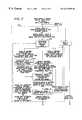
- FIG. 2illustrates functional blocks within a queuing module 200 implemented on the communication device 100 according to one embodiment of the present invention.
- the functional blocksare broken up into three vertical segments, namely, receive, control, and transmit, and two horizontal segments, namely non-interrupt and interrupt functions.
- the queuing module 200is implemented in software, in which case, the queuing module 200 or portions thereof is contained in the memory 120 and/or internal memory 108 of the CPU 105 , and is executed by the CPU 105 (FIG. 1 ).
- packets and framessuch as, for example, IP packets, Ethernet frames, and frame relay frames are received by a packet/frame input function 210 .
- the input function 210performs preliminary filtering and cyclic redundancy checking (“CRC”) on the packets and frames.
- CRCcyclic redundancy checking
- the packets and framesare then forwarded to a flow classification and routing block 218 .
- ATM cellsare received by a cell input function 212 .
- the cell input function 212determines whether there is an existing connection for the cell stream.
- the cellsare then passed to an adaptation layer processing block 214 where the cells are converted to contiguous protocol data units (“PDUs”) using, for example, ATM adaptation layer 5 (“AAL 5 ”).
- the adaptation layer processing block 214also detects Integrated Local Management Interface (“ILMI”), Operations, Administration, and Maintenance (“OAM”), and signaling cells, and passes them directly to a supervision message system block 220 for setting up/tearing down connections, etc.
- ILMIIntegrated Local Management Interface
- OAMOperations, Administration, and Maintenance
- signaling cellspasses them directly to a supervision message system block 220 for setting up/tearing down connections, etc.
- the adaptation layer processing block 214detects resource management cells relating to flow control (e.g., ATM available bit rate “ABR” RM cells, etc.), and passes these cells to a resource manager block 222 which then slows down or speeds up an existing flow in response to the management cells. After each PDU is reconstructed, it is passed to an ATM decapsulation layer block 216 where PDUs are decapsulated into data units using RFC 1483. The ATM decapsulation layer block 216 then forwards the data units to the flow classification and routing block 218 .
- resource management cells relating to flow controle.g., ATM available bit rate “ABR” RM cells, etc.
- the flow classification and routing block 218determines whether a flow has been set up for an incoming data unit, and determines the class of traffic that the flow is assigned. If a flow has been set up for the packet, the packet and an associated Flow ID are transmitted to a forwarding block 230 in the transmit segment.
- the Flow IDincludes several components including a destination link, the shaping/scheduling parameters of the flow, the quality of service (“QoS”) parameters assigned to the flow, etc. Assignment of the Flow ID is dependent on the classification of the flow.
- the class assigned to the flowdetermines the QoS to be provided for that flow.
- the Flow IDis an address pointing to a memory location where the aforementioned parameters are located.
- the packetis sent to the forwarding block 230 with a request that a flow be created for the packet at a desired QoS.
- An embodiment of the flow classification and routing block 218is described in co-pending U.S. patent application Ser. No. 09/261,061, entitled “Apparatus and Method for Classifying Information Received by a Communications System,” and now U.S. Pat. No. 6,295,532 filed Mar. 2, 1999, and assigned to the assignee of the present invention, the contents of which are incorporated herein by reference.
- VPC servicethe VPCs are ordered and leased from a service provider.
- the VPC configuration associated with the VPC service orderedis then placed in the configuration database 124 of the communication device 100 (FIG. 1 ).
- the VPCmay be manually configured, or automatically configured using protocols such as ILMI.
- the queuing module 200sets up level- 1 flows for the VPCs. Flow classification and policy definitions determine how to identify one protocol stream from another, in addition to the QoS parameters required to support each stream.
- a level- 2 flowis requested from a fly-by flow admission control block 232 via a forwarding application program interface (“API”) block 230 based upon the flow classification and policy definition.
- APIapplication program interface
- a level- 2 flowis requested, it is requested with a corresponding level- 1 Flow ID that was created by the user configuration.
- the flow classification and routing block 218use the configuration to determine routes and the set of level- 1 flows available to make level- 2 flows.
- Each level- 2 flow createdis assigned a level- 2 Flow ID and a VCC. The VCC assignment allows flows to be multiplexed at the cell level (e.g., one cell from one flow followed by one cell from another flow).
- VCC servicethe VCCs are also ordered and leased from the service provider.
- the VCC configuration associated with the VCC service orderedis then placed in the configuration database 124 of the communication device 100 (FIG. 1 ). This can be manually, or automatically configured using protocols such as ILMI.
- the queuing module 200sets up level- 1 flows for the VCCs. Flow classification and policy definitions determine how to identify one protocol stream from another and determine the QoS parameters required to support each stream. As data units are received on an interface for a class where a flow has not been established, a level- 2 flow is requested from the fly-by flow admission control block 232 via the forwarding API block 230 based upon the flow classification and policy definition.
- VCC servicedoes not assign VCCs to flows as in the VPC service. However, data structures for flow state machines are created and initialized as in VPC service. With VCC service, flows are multiplexed at the packet level (e.g., when a flow is chosen for output service, all segments of the packet are transmitted in consecutive succession before another flow is serviced).
- a connection management task 226(e.g., an ATM management task) and a physical interface management task 228 are provided and run with/on the operating system 122 (FIG. 1 ). These tasks operate in the non-interrupt code space and communicate with the resource manager 222 by way of an API using the supervision message system 220 .
- the APIis used to pass messages (e.g., LMI, OAM, and signaling information) between the tasks and the WAN interface.
- the resource manager 222sends requests for establishing, terminating, and modifying connections to the connection management task 226 .
- the connection management task 226responds to such requests directing the resource manager 222 to install, de-install, or modify the connections.
- the physical layer management task 228communicates with the resource manager 222 , notifying the latter of the (up/down) status of physical ports.
- the LMI, OAM, and signaling messages passed back to the supervision message system 220 from the connection management task 226are sent directly to a buffer management block 234 for queuing in queues 236 , and subsequent output.
- the resource manager 222handles the installation, de-installation, and modification of flows. This includes handling and generating resource management data to control the data rate for flow controlled connections such as, for example, ATM ABR.
- the resource manager 222is also responsible for mapping class and policy definitions for the flows. Such class and policy definitions include resource requirements (e.g., bandwidth, peak rate limits, buffer delay, and jitter).
- the resource manager 222assigns pre-established VCCs and flow state machine data structures for VPC service due to the activation/deactivation of the flows (e.g., layer- 3 to layer- 7 protocol flows such as IP).
- Activation of flowsoccurs upon data unit arrivals, or signaling protocols (e.g., ATM SVC Signaling or Resource RerserVation Protocol “RSVP”) that require a flow be established. Deactivation of flows occurs upon timeouts for flows (e.g., data unit arrivals not received for a predetermined amount of time), or by signaling protocols such as ATM SVC signaling and RSVP.
- the resource manager 222is coupled to a flow database 224 which contains the current resource state (e.g., available bandwidth for allocation, available buffers for allocation, etc.).
- the flow database 224includes other parameters and state variables including, but not limited or restricted to, Flow ID used to map, for example, a layer- 3 protocol (e.g., IP) classified flow into a level- 2 VCC, connection shaping parameters and state (e.g., QoS parameters such as peak and sustained bandwidth, maximum queuing delay, maximum burst size, etc.), and connection scheduling parameters and state (e.g., sustained rate).
- the resource manager 222allocates resources for flows and keeps track of remaining resources using the flow database 224 . It determines whether resources can be allocated to flows and reclaims resources for flows no longer active.
- an example of a resource request to the resource manager 222may include the following:
- VPCATM connection type
- VPNVirtual path identifier
- VCIVirtual connection identifier
- Traffic contracte.g., ABR, UBR, VBR, CBR, GFR
- Buffer allocation(e.g., number of buffers);
- ATM VCC endpoint function assignment(e.g., AAL 5 , AAL 2 , ILMI);
- Encapsulation Type(e.g., 1483, null, etc.);
- VCCHierarchy Level- 2 assignment
- AAL 2 VCCAAL 5 packet mode VCC
- the connection management task 226upon initialization, interfaces with the operating system 122 running on the communication device 100 and reads the configuration information in the connection database 124 to install the user configurations (FIG. 1 ). If there is a VPC service to be configured, the connection management task 226 issues a request to the resource manager block 222 to install a level- 1 flow (and requests a QoS) for the VPC. The resource manager block 222 then establishes a level- 1 flow and assigns resources to the flow. The resource manager block 222 then sends a deny or confirmation message and a Flow ID back to the connection management task block 226 . A deny message indicates that there are insufficient resources available if the request indicated to deny in the case of insufficient resources.
- a confirmation messageindicates that there were either sufficient resources and a flow assigned, or insufficient resources (e.g., less than requested resources) and a flow assigned.
- a similar protocolis performed for VCC service.
- the connection management task block 226then notifies the flow classification and routing block 218 of the set of VPCs and VCCs (level- 1 flows) that are set up to be used by sending the Flow IDs of the VPCs and VCCs to the same.
- the forwarding API block 230passes data units, Flow IDs, and/or requests for assignment of Flow IDs and QoS from the flow classification and routing block 218 to a fly-by flow admission control block 232 .
- the fly-by flow admission control block 232performs admission control for data unit arrivals for which there is no assigned flow. This is required due to the connectionless nature of many protocol layers (e.g., IP).
- the fly-by flow admission control block 230interacts with the flow classification and routing block 218 to map protocol layer flows to level- 1 or level- 2 flows.
- connection management task 226creates pre-configured level- 2 flows between the source and destination node on which it can map a layer protocol flow to the level- 2 flow (e.g., mapping a new layer- 3 protocol such as IP, or a layer- 2 protocol such as frame relay or PPP to a level- 2 flow).
- a layer protocol flowe.g., mapping a new layer- 3 protocol such as IP, or a layer- 2 protocol such as frame relay or PPP to a level- 2 flow.
- Each pre-configured level- 2 flowis initially setup without any QoS parameters assigned to it.
- the flow classification and routing block 218passes data units and their corresponding Flow IDs to the fly-by flow admission control block 232 for existing flows.
- the fly-by flow admission control block 232then forwards the data units to the buffer management block 234 for queuing.
- the flow classification and routing block 218passes a resource request to the fly-by flow admission block 232 for the QoS parameters for a new flow.
- QoS parametersinclude, but are not limited or restricted to, peak rate, sustained rate, delay, jitter, and maximum burst size.
- the fly-by flow block 232attempts to acquire resources for the flow by sending a request to the resource manager 222 .
- the resource manager 222determines whether there are sufficient resources such as bandwidth, buffers, connection identifiers, delay bounded routes, etc. to meet the desired QoS associated with the flow, as indicated by the policy associated with the class.
- the fly-by flow admission block 232is notified to acquire a level- 2 flow out of a pool of available level- 2 flows that have not been assigned to protocol layers (e.g., layer- 2 or layer- 3 classified flows).
- the fly-by flow admission block 232then assigns to the level- 2 flow, the QoS parameters requested by the flow classification and routing block 218 in the QoS request.
- the data unitis then forwarded to the buffer management block 234 for queuing. Consequently, the level- 2 flow is active and able to accept and queue data units. If there are insufficient resources, the flow may be denied or accepted on an “all-others” flow (e.g., lower priority flow) as pre-determined by user configuration control.
- flow classification and routing block 218wishes to terminate the protocol layer flow, it requests the resource manager 222 to deactivate the level- 2 flow. All resources that were used by the level- 2 flow are returned to the resource pool and the flow is deactivated. When deactivated, the level- 2 flow is no longer available to be used until it is reassigned to a new layer- 3 or layer- 2 flow.
- the fly-by flow admission control block 232has the advantage over explicit out-of-band flow establishment procedures such as ATM signaling or RSVP in that the data unit is not delayed by the out-of-band flow establishment process that requires communication between networking devices. Thus, with the fly-by flow admission block 232 , the first data unit to establish a flow is not delayed and can be immediately forwarded to the network port. This makes applications such as Voice over IP a reality in the WAN.
- Resources assigned to level- 1 flowscan be partitioned for purposes of limiting access.
- the sum of the resource partitionsis equal to the resource assignment to the level- 1 flow.
- a level- 1 flowmay have two resource partitions, one for agency A and one for agency B (e.g., for separate LAN networks).
- agency Acan be limited in the amount of resources that are drawn from the level- 1 flow so as not to block resources from being allocated to flows belonging to agency B.
- agency Bhas its own resource partition to draw from as not to block agency A.
- the buffer-management block 234determines whether the queue has sufficient space for the data unit. If not, the data unit is discarded. If so, the data unit is queued in the data unit queues 236 associated with the flow. A queue is assigned to each flow. The queue operates as a FIFO and can accept packet, frames, and cells.
- Queues/buffersare allocated for each VPC, VCC, or UNI. This is used to prevent connections from depleting the buffer pool thus blocking other connections from being able to queue data for transmission. It can also be used to bound the queuing delay for a flow.
- a flowonly uses the buffers allocated to the associated VPC, VCC, or UNI. If a flow depletes its buffer allocation, even though there are available buffers in the system, the data unit is discarded. For cases where there are a relatively large number of connections and/or interfaces, buffer allocation can be configured so that the buffers are over-allocated. This results in more buffers being available on a statistical basis with a chance that a flow might not at times be able to use its allocation. For example, 10,000 buffers are allocated to a UNI. As long as a majority of the connections are idle or have not used their entire buffer allocation, active connections can queue more packets and cells than if their buffer allocation were limited to 100 buffers.
- the queues 236are coupled to a two-tiered hierarchical shaper/scheduler block 238 , having a hierarchy level- 1 shaper/scheduler and a hierarchy level- 2 shaper/scheduler, that selects a flow for service. If the packet arrives into a non-empty queue, the flow has already been scheduled and no further action is required. That is, once a packet is queued, the flow associated with the packet is sent to the shaper/scheduler block 238 for shaping and scheduling. The shaper/scheduler block 238 is invoked periodically to service the queues 236 . When a flow is selected for output, the associated output adaptation processing assigned to the flow is performed and the data is delivered to an output port. For example, for ATM, the output function is the ATM encapsulation layer block 240 which applies the RFC 1483 header to the packet. The packet is then passed to the ATM adaptation layer block 242 which segments packets into cells and outputs the cells.
- FIG. 3illustrates a diagram 300 of single and dual tiered flows on a UNI that are supported by the queuing module 200 , according to one embodiment of the present invention.
- the single tiered flow(column 310 ) is a level- 1 flow without the ability to accept level- 2 flows.
- the single tiered flowconserves memory and computational resources when there is no desire to carry multiple level- 2 flows on a level- 1 flow.
- Flow data unit queuesare assigned to the level- 1 flow.
- a hierarchical level- 1 shaper/scheduleris used for VCC shaping and scheduling, and the hierarchical level- 2 shaper/scheduler is used for packet shaping and scheduling.
- VCCsare mapped to level- 1 flows (e.g., a layer protocol flow such as ATM), and layer protocol flows (e.g., IP) are mapped to level- 2 flows.
- layer protocol flowse.g., IP
- For VCC service with layer protocol flowsdepending upon the ATM adaptation layer used (e.g. AAL 5 ), all segments of a packet may or may not need to be sent out before a new flow can be selected for output service.
- the dual tiered flow(column 320 ) is a level- 1 flow with the ability to accept level- 2 flows.
- the level- 1 flowis assigned to a level- 2 shaper/scheduler.
- the level- 1 shaper/schedulerselects the level- 1 flow for output service.
- the level- 1 flowprocesses the level- 2 shaper/scheduler that is assigned to it.
- the level- 2 shaper/schedulerselects a flow for output service and an output function (e.g., AAL 5 ) is invoked to output a data unit.
- an output functione.g., AAL 5
- the hierarchical level- 1 shaper/scheduleris used for VPC shaping and scheduling
- a hierarchical level- 2 shaper/scheduleris used for VCC shaping and scheduling.
- VCCs within VPCsare assigned to the level- 2 shaper/schedulers.
- this modeallows VCCs to be shaped and scheduled within VPCs.
- Level- 2 flowsare queued in level- 2 shaper/schedulers
- level- 1 flowsare queued in level- 1 shaper/schedulers.
- VPC and VCC servicesIn addition to VPC and VCC services, other services may exist.
- a hybrid servicecomprising of a combination of the VPC service and the VCC service may be offered on the same UNI.
- the single and dual tiered flows shown in FIG. 3are thus illustrative and not intended as a limitation of the services supported.
- FIG. 4illustrates a functional block diagram of a two-tiered hierarchical shaper/scheduler and buffer manager, according to one embodiment of the present invention.
- the two-tiered hierarchical shaper/scheduler and buffer managerincludes the buffer management block 234 , the queues block 236 , and the two-tiered hierarchical shaper/scheduler block 238 of FIG. 2 .
- the buffer-management block 234queues the data units depending on whether there are available unallocated or sufficient allocated buffers for the associated VCC, VPC, and/or UNI. Otherwise, the buffer management block 234 discards the data units. If there are sufficient buffering capacity, the data units are queued in queues 236 .
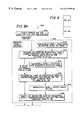
- FIG. 5illustrates a flow diagram of a buffer management method 400 according to one embodiment of the present invention.
- a data unit arrivaloccurs for transmission to link K.
- a determinationis made as to whether the number of data units queued for the associated flow (e.g., VCC) is below a maximum threshold. If not, the data unit is discarded. If the data unit does not exceed the maximum threshold for the flow, and the flow is assigned to a level- 2 shaper/scheduler, the process moves to block 420 . If the flow is assigned to the level- 1 shaper/scheduler, the process moves to block 430 .
- VCCnumber of data units queued for the associated flow
- the number of data units queued for the hierarchy level- 2 shaper/schedulere.g., sum of VCCs for the associated VPC or VCC aggregate
- the queues 236include a plurality of level- 2 queues 315 1 - 315 P and a level- 1 queue 320 .
- Data units admitted through the buffer manager 234are placed in a level- 2 queue or the level- 1 queue.
- the two-tiered hierarchical shaper/scheduler 238includes level- 2 shaper/schedulers 335 1 - 335 P , and a level- 1 shaper/scheduler 340 .
- Level- 2 shaper/schedulers 335 1 - 335 Pcorrespond to level- 2 queues 315 1 - 315 P .
- a UNImay be assigned to the level- 1 shaper/scheduler 340 , and a level- 1 flow may be assigned to a level- 2 shaper/scheduler 330 . If the flow is a single tiered flow, it is queued in the level- 1 shaper/scheduler 340 . Similarly, if the flow is a level- 2 flow of a dual tiered flow, it is queued in the level- 2 shaper/scheduler 330 . In turn, if not already scheduled, the level- 2 shaper/scheduler 330 is queued in the level- 1 shaper/scheduler 340 .
- the level- 1 shaper/scheduler 340chooses a level- 1 flow or a level- 2 shaper/scheduler 330 that has the smallest timestamp deadline (discussed below). If the hierarchy level- 1 shaper/scheduler 340 chooses a level- 1 flow, the output function 350 (e.g., an ATM adaptation layer or OAM function) associated with the flow is invoked. The ATM adaptation layer or OAM function builds a cell's worth of data for subsequent transmission. If the level- 1 shaper/scheduler 340 selects a level- 2 shaper/scheduler 340 , the level- 2 shaper/scheduler selects a level- 2 flow. Then, the ATM adaptation layer or OAM function 350 builds a cell's worth of data for subsequent transmission.
- the output function 350e.g., an ATM adaptation layer or OAM function
- Shapingis a function of limiting the maximum rate at which data units can be transmitted for any given flow.
- leaky-bucketFor ATM, this is the peak cell rate of an unspecified bit rate (“UBR”) traffic contract.
- UBRunspecified bit rate
- the link bandwidthis 1000 cells/sec and a UBR peak cell rate is 500 cells/sec
- shapinglimits the cell rate for the connection to 500 cells/sec even if there is an offered load that exceeds the peak rate. If cells were transmitted at a rate greater than 500 cells/sec, the ATM Network might discard that portion of the traffic above the peak rate. Even though there is bandwidth available on the link, it is not necessarily utilized. This property makes shaping a non-work-conserving mechanism.
- schedulingis a work-conserving mechanism. Unlike shaping, which applies to each flow, scheduling looks at all the flows and makes a determination as to which flow to service next and transmit a data unit from the flow. As long as there are data units queued, it selects a data unit to transmit every link data unit time. The selection of which data unit to transmit is based upon a scheduling discipline, as will be described in the following sections.
- FIG. 6illustrates a functional block diagram of a hierarchy level- 2 shaper/scheduler 335 and a corresponding level- 2 flow queue 315 according to one embodiment of the present invention.
- the level- 2 shaper/scheduler 335includes a hierarchy level- 2 peak rate quarantine queue (“H 2 -PRQQ”) 510 , a hierarchy level- 2 allocated rate quarantine queue (“H 2 -ARQQ”) 520 , and a hierarchy level- 2 output queue 530 (“H 2 -OQ”).
- Data unitsare queued in the queue 315 as they arrive.
- the flow associated with the data unitis also queued in the level- 2 shaper/scheduler 335 queues. If a data unit is received when the flow is already queued in the level- 2 shaper/scheduler 335 queues, the data unit is queued in the level- 2 queue 315 and no other action is performed.
- the flowis forwarded to block 505 where the data unit arrival rate is determined.
- the arrival rateis compared to the last data unit departure for the flow. If the comparison is less than or equal to the allocated rate for the flow as determined by comparison to the “no-rush” condition, the flow is queued in the H 2 -OQ 530 .
- the “no-rush” conditionis defined in Suri et al., entitled “Leap Forward Virtual Clock: A New Fair Queuing Scheme With Guaranteed Delays And Throughput Fairness”, published by Washington University, Department of Computer Science, October 1997.
- the L and H queuesare analogous to the H 2 -ARQQ 520 and H 2 -OQ 530 , respectively, of FIG. 6 .
- the flowis queued in the H 2 -ARQQ 520 .
- the flowis held in the H 2 -ARQQ 520 until the difference between the current flow timestamp and the last cell departure timestamp is equal to the allocated inter-cell rate as determined by comparison to the no-rush condition, at which time it is transferred to the H 2 -OQ 530 .
- the comparisonis greater than the permissible peak rate for the flow, the flow is queued in the H 2 -PRQQ 510 .
- the flowis held in the H 2 -PRQQ 510 until the difference between the current flow timestamp and the last cell departure timestamp is equal to the permissible inter-cell peak rate at which time it is transferred to the H 2 -ARQQ 520 .
- the H 2 -OQ 530is serviced when selected by the level- 1 shaper/scheduler 340 (FIG. 4 ). Flows compete for the next cell transmission time and the flow with the earliest timestamp deadline is the flow to be serviced.
- the flowis serviced by invoking the flow's output function to output a data unit. In the case of ATM, the output function gathers a cell's worth of data from the queue 315 for output.
- the server clockis advanced such that at least one flow in the H 2 -ARQQ 520 is eligible for transfer to the H 2 -OQ 530 .
- the flowis rescheduled for the next data unit, as shown by the arrow from the H 2 -OQ 530 to block 505 .
- FIG. 7illustrates a functional block diagram of the level- 1 shaper/scheduler 340 and the corresponding level- 1 queue 320 according to one embodiment of the present invention.
- the level- 1 shaper/scheduler 340includes a hierarchy level- 1 peak rate quarantine queue (“H 1 -PRQQ”) 610 , a hierarchy level- 1 allocated rate quarantine queue (“H 1 -ARQQ”) 620 , and a hierarchy level- 1 output queue (“H 1 -OQ”) 630 .
- the level- 1 shaper/scheduler 340services flows of the level- 2 shaper/schedulers 335 and level- 1 flows.
- the level- 2 shaper/scheduler, if not already queued, or level- 1 flowis transferred to block 605 where the data unit arrival rate is determined.
- the level- 2 shaper/scheduler 335For the level- 2 shaper/scheduler, after data units are queued in the level- 2 shaper/scheduler 335 , the level- 2 shaper/scheduler 335 itself is queued in the level- 1 shaper/scheduler 340 . If the level- 2 shaper/scheduler 335 is already queued in the level- 1 shaper/scheduler, then there is no further processing. If the level- 2 shaper/scheduler 335 arrival is less than or equal to the allocated rate for the flow, the level- 2 shaper/scheduler 335 is queued in the H 1 -OQ 630 .
- the level- 2 shaper/scheduler 335is queued in the H 1 -ARQQ 620 .
- the level- 2 shaper/scheduleris held in the H 1 -ARQQ 620 until the difference between the current flow timestamp and the last cell departure timestamp is equal to the allocated inter-cell rate, as determined by the “no rush” condition. At that time, it is transferred to the H 1 -OQ 630 .
- the level- 2 shaper/scheduleris queued in the H 1 -PRQQ 610 where it is held until the difference between the current flow timestamp and the last cell departure timestamp is equal to the permissible inter-cell peak rate, at which time it is transferred to the H 1 -ARQQ 620 .
- the H 1 -OQ 630is serviced every output transmission service period.
- the service periodis a period of time that it takes to transmit a data unit.
- the level- 2 shaper/schedulerscompete for the next data unit transmission time and the level- 2 shaper/scheduler with the earliest timestamp deadline in the H 1 -OQ 630 is the shaper/scheduler to be serviced.
- the level- 2 shaper/scheduleris serviced by invoking the level- 2 shaper/scheduler's output function to output a data unit.
- the level- 1 shaper/scheduler 340 operationis similar to the level- 2 shaper/scheduler 335 operation.
- FIGS. 8A and 8Billustrate (FIG. 8) an enqueuing process 700 of the two-tiered hierarchy shaper/scheduler 238 of FIG. 2, according to one embodiment of the present invention.
- the flowis forwarded to block 710 where a determination is made as to whether the flow is a level- 1 flow or a level- 2 flow.
- the flowbypasses the hierarchy level- 2 shaper/scheduler 335 and is passed directly to the hierarchy level- 1 shaper/scheduler 340 .
- a timestampis generated for the flow using a peak rate shaper timestamp generator (block 750 ). The flow then moves to block 755 where the difference between the current time and the last departure time is determined. If the flow exceeds the permissible peak rate, the flow is moved into the H 1 -PRQQ 610 and is ineligible for output.
- a timestampis generated for the flow using an allocated rate scheduler timestamp generator (block 760 ).
- the timestamp generatorassigns timestamps to values based upon the ATM VCC connection type.
- UBRactually has zero minimum rate, in one embodiment, the smallest possible rate is assigned to the connection. Assigning minimal bandwidth to UBR connections avoids complicating the shaper/scheduler algorithm. Thus, some bandwidth allocation keeps UBR connections from being starved indefinitely.
- the flowis queued in either the H 1 -ARQQ 620 or the H 1 -OQ 630 depending upon a test to see if the flow is violating a “no-rush” condition.
- the “no-rush” conditiontests to see if a flow arrival rate is greater than its allocated rate. If the flow arrival rate is greater than the allocated rate, the flow is queued in the H 1 -ARQQ 620 , otherwise it is queued in the H 1 -OQ 630 for transmission on the link.
- the flowis passed to the hierarchy level- 2 shaper/scheduler 335 .
- a timestampis generated for the flow using a peak rate shaper timestamp generator (block 720 ).
- the flowthen moves to block 725 where the difference between the current time and the last departure time is determined. If the flow exceeds the permissible peak rate, the flow is moved into the H 2 -PRQQ 510 and is ineligible for output.
- the hierarchy level- 2 shaper/scheduler 335is queued in the hierarchy level- 1 shaper/scheduler 340 . If the flow timestamp has an earlier deadline than the hierarchy level- 2 shaper/scheduler 335 timestamp that is contained the hierarchy level- 1 shaper/scheduler 340 and the hierarchy level- 2 shaper/scheduler 335 is queued in the level- 1 shaper/scheduler's H 1 -PRQQ 610 , then the level- 2 shaper/scheduler 335 is removed from and re-queued in the H 1 -PRQQ 610 with the earlier deadline timestamp.
- the level- 2 shaper/scheduler 335is not queued in the H 1 -PRQQ 610 with a peak rate that is greater than the peak rate assigned to the level- 2 shaper/scheduler. For example, if the level- 2 shaper/scheduler, having a peak interval of ⁇ fraction (1/10) ⁇ data units, is queued in the H 1 -PRQQ, and a subsequent flow is received in the H 2 -PRQQ having a peak interval of 1 ⁇ 8, the level- 2 shaper/scheduler will not be re-queued.
- a timestampis generated for the flow using an allocated rate scheduler timestamp generator (block 730 ).
- the timestamp generatorassigns timestamps to values based upon the ATM VCC connection bandwidth parameters.
- the flowis then queued in either the H 2 -ARQQ 520 or the H 2 -OQ 530 .
- the hierarchical level- 2 shaper/scheduler 335itself is queued in the hierarchy level- 1 shaper/scheduler.
- the hierarchy level- 1 shaper/schedulergenerates a timestamp for the hierarchy level- 2 shaper/scheduler using the level- 1 peak rate shaper timestamp generator (block 750 ).
- the timestamp generatorassigns timestamps to values based upon the ATM VPC connection bandwidth parameters.
- the process for the hierarchy level- 2 shaper/scheduleris the same for a level- 1 flow as described above.
- FIGS. 9A and 9Billustrate (FIG. 9) a dequeuing process 800 of the two-tiered hierarchy shaper/scheduler 238 of FIG. 2, according to one embodiment of the present invention.
- the dequeuing process 800commences at block 805 where there is an output service request for a data unit. If the H 1 -OQ 630 is empty, the server time is advanced to the least timestamp value in H 1 -ARQQ 620 .
- the hierarchy level- 1 shaper/scheduler 340then transfers all eligible hierarchy level- 1 flows or hierarchy level- 2 shaper/schedulers from the H 1 -PRQQ 610 to the H 1 -ARQQ 620 depending upon the peak rate condition (block 810 ), and the H 1 -ARQQ 620 to the H 1 -OQ 630 depending upon the no-rush condition. Then the hierarchy level- 1 flows or the hierarchy level- 2 shaper/scheduler with the earliest deadline timestamp in the H 1 -OQ 630 is selected. If there are no active flows or hierarchy level- 2 shaper/schedulers, then a no data unit event is generated and the output function is invoked.
- an idle cellis generated for output.
- the hierarchy level- 2 shaper/scheduler 335is bypassed and the output function associated with the hierarchy level- 1 flow (block 865 ) is invoked.
- the selected hierarchy level- 2 shaper/scheduler 335is invoked.
- the hierarchy level- 2 shaper/scheduler 335proceeds in a similar fashion as the hierarchy level- 1 shaper/scheduler 340 by transferring flows from the H 2 -PRQQ 510 to the H 2 -ARQQ 520 , and transferring flows from the H 2 -ARQQ 520 to the H 2 -OQ 530 . Then the H 2 -OQ 530 is scanned for the flow with the earliest deadline timestamp. For the flow selected, the flow's associated output function is invoked. After the output function has completed, if the associated hierarchy level- 1 flow or hierarchy level- 2 shaper/scheduler is still active (has more data units queued), the enqueuing process 700 is invoked.
- the no-rush conditionmay be modified so that the flow to be serviced is greater than its allocated rate for a short period of time, at a cost of slight unfairness to other flows. This enables trading off computational complexity to short-term fairness for a large number of flows.
- WFQWeighted Fair Queuing
- computational complexityis on the order of N (O(N)) per packet transmission where “N” is the number of flows managed.
- Nis the number of flows managed.
- the complexity of WFQprecludes it from being a practical solution for a large number of flows and/or high-speed interfaces.
- WFQis excluded from any software-based implementations for a large number of flows or high-speed interfaces.
- the computational complexity of the queuing module 200 of the present inventionis O(log(logN)) per packet transmission.
- the present inventionis scalable to high rates that typically have a large number of flows, making it a candidate for Gigabit interface speeds.
- WFQexhibits burstiness over short intervals causing an oscillatory behavior that is undesirable for feedback based congestion control.
- WFQis not inherently compatible with ABR ATM services.
- the queuing modulesmoothes out burstiness, making it an ideal candidate for ABR.
- the queuing module smoothing characteristicsprovides a better “fairness index” than WFQ.
- WFQuses weights for flows.
- the weightsare relative to the link speed.
- the present inventionallocates bandwidth that is compatible with traffic contracts provided by WAN services.
- the present inventionimmediately adapts to changes in link rate. This is important for inverse multiplexing over AT (“IMA”) where individual physical links may come in and out of service. It is also important for offering various virtual connection traffic contracts within VBR or ABR virtual path services. Since WFQ uses weights for flows, it cannot provide bandwidth allocation service guarantees as available bandwidth changes.
- IMAinverse multiplexing over AT
- the present inventionis further extensible to add support to control cell delay variations for delay-variation sensitive flows such as AAL 1 CBR flows.
- WPQhas no such extensibility.
- the present inventiontimestamps data unit arrivals and departures, it inherently supports service level agreement (“SLA”) measurements.
- SLAservice level agreement
- Time-stamping mechanismsmust be used in addition to WFQ for support of SLAs, further increasing the computational complexity of WFQ.
- WFQdue to the extreme computational complexity of WFQ, it is not practical to implement WFQ in a hierarchical arrangement.
- the present inventionintegrates shaping and scheduling to keep the overall shaping and scheduling computation complexity to O(log(logN)). Since WFQ does not allocate peak rate bandwidth to connections, it cannot be used for shaping. Other mechanisms must be used in addition to WFQ to make the flows conforming to ATM traffic contracts of service providers.
- WFQdoes not scale for a large number of connections.
- WFQ searches for 65,536 active virtual connectionsrequire a maximum search depth of 65,536.
- the present inventionscales for a large number of virtual connections. That is, searches for 65,536 active virtual connections can be accomplished with a maximum search depth of four (4). Queue searches for 4,000,000,000 active virtual connections can be accomplished with a maximum search depth of five (5).
Landscapes
- Engineering & Computer Science (AREA)
- Computer Networks & Wireless Communication (AREA)
- Signal Processing (AREA)
- Quality & Reliability (AREA)
- Data Exchanges In Wide-Area Networks (AREA)
Abstract
Description
Claims (21)
Priority Applications (1)
| Application Number | Priority Date | Filing Date | Title |
|---|---|---|---|
| US09/261,039US6519595B1 (en) | 1999-03-02 | 1999-03-02 | Admission control, queue management, and shaping/scheduling for flows |
Applications Claiming Priority (1)
| Application Number | Priority Date | Filing Date | Title |
|---|---|---|---|
| US09/261,039US6519595B1 (en) | 1999-03-02 | 1999-03-02 | Admission control, queue management, and shaping/scheduling for flows |
Publications (1)
| Publication Number | Publication Date |
|---|---|
| US6519595B1true US6519595B1 (en) | 2003-02-11 |
Family
ID=22991711
Family Applications (1)
| Application Number | Title | Priority Date | Filing Date |
|---|---|---|---|
| US09/261,039Expired - LifetimeUS6519595B1 (en) | 1999-03-02 | 1999-03-02 | Admission control, queue management, and shaping/scheduling for flows |
Country Status (1)
| Country | Link |
|---|---|
| US (1) | US6519595B1 (en) |
Cited By (54)
| Publication number | Priority date | Publication date | Assignee | Title |
|---|---|---|---|---|
| US20020018474A1 (en)* | 2000-06-01 | 2002-02-14 | Seabridge Ltd. | Efficient packet transmission over ATM |
| US20020082814A1 (en)* | 1999-12-29 | 2002-06-27 | Ge Harris Railway Electronics Llc | A Yard Performance Model Based on Task Flow Modeling |
| US20020120720A1 (en)* | 2000-09-01 | 2002-08-29 | Ian Moir | Method and system to pre-compile configuration information for a data communications device |
| US20020147816A1 (en)* | 2001-02-28 | 2002-10-10 | Hlasny Daryl J. | Pseudo-random dynamic scheduler for scheduling communication periods between electronic devices |
| US20020194372A1 (en)* | 2001-06-08 | 2002-12-19 | Yehuda Elmaliach | Class-based per-flow queuing across multiple hierarchical link-sharing structures |
| US20030088682A1 (en)* | 2001-02-28 | 2003-05-08 | Hlasny Daryl J | Communication period management in a communication system |
| US20030097460A1 (en)* | 2001-11-22 | 2003-05-22 | Anritsu Corporation | Relay apparatus and relay method suitable for performing communication to ensure quality of service |
| US6608839B1 (en)* | 1999-01-25 | 2003-08-19 | Paradyne Corporation | System and method for indicating an accurate committed information rate |
| US20030223430A1 (en)* | 2002-06-04 | 2003-12-04 | Sandeep Lodha | Distributing unused allocated bandwidth using a borrow vector |
| US20040022260A1 (en)* | 2002-05-29 | 2004-02-05 | Raytheon Company | Method and system for encapsulating cells |
| US20040064815A1 (en)* | 2002-08-16 | 2004-04-01 | Silverback Systems, Inc. | Apparatus and method for transmit transport protocol termination |
| US20040114517A1 (en)* | 2002-12-12 | 2004-06-17 | International Business Machines Corporation | Method and apparatus for hierarchial scheduling of virtual paths with underutilized bandwidth |
| US6760312B1 (en)* | 1999-11-30 | 2004-07-06 | Lucent Technologies Inc. | Quality of service on demand |
| US20040252711A1 (en)* | 2003-06-11 | 2004-12-16 | David Romano | Protocol data unit queues |
| US20050018601A1 (en)* | 2002-06-18 | 2005-01-27 | Suresh Kalkunte | Traffic management |
| US20050050113A1 (en)* | 2003-08-21 | 2005-03-03 | International Business Machines Corporation | System and method for facilitating data flow between synchronous and asynchronous processes |
| US20050063388A1 (en)* | 1999-12-28 | 2005-03-24 | Dave Stacey | ATM packet scheduler |
| US20050213507A1 (en)* | 2004-03-25 | 2005-09-29 | International Business Machines Corporation | Dynamically provisioning computer system resources |
| US20060028982A1 (en)* | 2004-08-06 | 2006-02-09 | Wright Steven A | Methods, systems, and computer program products for managing admission control in a regional/access network based on implicit protocol detection |
| WO2006060867A1 (en)* | 2004-12-09 | 2006-06-15 | Commonwealth Scientific And Industrial Research Organisation | Traffic shaping with delay constraints |
| US20060149765A1 (en)* | 2004-12-30 | 2006-07-06 | Joseph Knoerle | Methods, systems, and computer program products for managing system resources |
| US20070156304A1 (en)* | 2005-12-30 | 2007-07-05 | Canadian National Railway Company | System and method for computing rail car switching solutions using dynamic classification track allocation |
| US20070156301A1 (en)* | 2005-12-30 | 2007-07-05 | Canadian National Railway Company | System and method for computing rail car switching solutions in a switchyard using an iterative method |
| US20070156308A1 (en)* | 2005-12-30 | 2007-07-05 | Canadian National Railway Company | System and method for computing rail car switching solutions in a switchyard with partially occupied classification track selection logic |
| US20070156303A1 (en)* | 2005-12-30 | 2007-07-05 | Canadian National Railway Company | System and method for computing rail car switching solutions in a switchyard including logic to re-switch cars for arrival rate |
| US20070156302A1 (en)* | 2005-12-30 | 2007-07-05 | Canadian National Railway Company | System and method for computing car switching solutions in a switchyard using car ETA as a factor |
| US20070156300A1 (en)* | 2005-12-30 | 2007-07-05 | Canadian National Railway Company | System and method for computing rail car switching solutions in a switchyard including logic to re-switch cars for block pull time |
| US20070156298A1 (en)* | 2005-12-30 | 2007-07-05 | Canadian National Railway Company | System and method for computing rail car switching solutions by assessing space availability in a classification track on the basis of arrival profile |
| US20070156307A1 (en)* | 2005-12-30 | 2007-07-05 | Canadian National Railway Company | System and method for computing rail car switching solutions in a switchyard including logic to re-switch cars for block size |
| US20070156299A1 (en)* | 2005-12-30 | 2007-07-05 | Canadian National Railway Company | System and method for computing rail car switching solutions by assessing space availability in a classification track on the basis of block pull time |
| US20070179688A1 (en)* | 2005-12-30 | 2007-08-02 | Canadian National Railway Company | System and method for computing rail car switching solutions in a switchyard |
| US20070239505A1 (en)* | 2006-03-30 | 2007-10-11 | Microsoft Corporation | Abstract execution model for a continuation-based meta-runtime |
| US20070239498A1 (en)* | 2006-03-30 | 2007-10-11 | Microsoft Corporation | Framework for modeling cancellation for process-centric programs |
| US20070299570A1 (en)* | 2005-12-30 | 2007-12-27 | Kari Muinonen | System and method for forecasting the composition of an outbound train in a switchyard |
| US7321940B1 (en)* | 2003-06-30 | 2008-01-22 | Cisco Technology, Inc. | Iterative architecture for hierarchical scheduling |
| US20080119973A1 (en)* | 2005-12-30 | 2008-05-22 | Anshu Pathak | System and method for computing rail car switching sequence in a switchyard |
| US20080244590A1 (en)* | 2003-06-25 | 2008-10-02 | International Business Machines Corporation | Method for improving performance in a computer storage system by regulating resource requests from clients |
| US7562168B1 (en) | 2008-05-29 | 2009-07-14 | International Business Machines Corporation | Method of optimizing buffer usage of virtual channels of a physical communication link and apparatuses for performing the same |
| US20090259353A1 (en)* | 2005-12-30 | 2009-10-15 | Kari Muinonen | System and method for computing railcar switching solutions in a switchyard using empty car substitution logic |
| US20090262645A1 (en)* | 2008-04-22 | 2009-10-22 | Tellabs Oy Et Al. | Method and equipment for shaping transmission speed of data traffic flow |
| US20100278190A1 (en)* | 2009-04-29 | 2010-11-04 | Yip Thomas C | Hierarchical pipelined distributed scheduling traffic manager |
| US20120020249A1 (en)* | 2010-05-18 | 2012-01-26 | Lsi Corporation | Packet draining from a scheduling hierarchy in a traffic manager of a network processor |
| WO2012145841A1 (en)* | 2011-04-28 | 2012-11-01 | Alcatel Lucent | Hierarchical profiled scheduling and shaping |
| US20120300624A1 (en)* | 2011-05-25 | 2012-11-29 | Fujitsu Limited | Bandwidth guaranteeing apparatus and bandwidth guaranteeing method |
| US8595478B2 (en) | 2000-07-10 | 2013-11-26 | AlterWAN Inc. | Wide area network with high quality of service |
| US8897292B2 (en) | 2012-12-31 | 2014-11-25 | Telefonaktiebolaget L M Ericsson (Publ) | Low pass filter for hierarchical pipelined distributed scheduling traffic manager |
| US9065741B1 (en)* | 2003-09-25 | 2015-06-23 | Cisco Technology, Inc. | Methods and apparatuses for identifying and alleviating internal bottlenecks prior to processing packets in internal feature modules |
| US20150249622A1 (en)* | 2014-03-03 | 2015-09-03 | Ericsson Television Inc. | Conflict detection and resolution in an abr network |
| US20160112292A1 (en)* | 2014-10-20 | 2016-04-21 | Arista Networks, Inc. | Method and system for non-tagged based latency calculation |
| US20160188367A1 (en)* | 2014-12-29 | 2016-06-30 | Huawei Technologies Co., Ltd. | Method for scheduling user request in distributed resource system, and apparatus |
| US9455932B2 (en) | 2014-03-03 | 2016-09-27 | Ericsson Ab | Conflict detection and resolution in an ABR network using client interactivity |
| US9755984B1 (en)* | 2005-02-08 | 2017-09-05 | Symantec Corporation | Aggregate network resource utilization control scheme |
| US10993147B1 (en)* | 2015-02-25 | 2021-04-27 | Satcom Direct, Inc. | Out-of-band bandwidth RSVP manager |
| US20250112867A1 (en)* | 2023-09-29 | 2025-04-03 | Nokia Solutions And Networks Oy | Universal hierarchical shaper for network determinism in generic network topologies |
Citations (7)
| Publication number | Priority date | Publication date | Assignee | Title |
|---|---|---|---|---|
| US4893307A (en)* | 1988-02-29 | 1990-01-09 | International Business Machines Corporation | Method and apparatus for linking SNA terminals to an SNA host over a packet switched communications network |
| US5021949A (en)* | 1988-02-29 | 1991-06-04 | International Business Machines Corporation | Method and apparatus for linking an SNA host to a remote SNA host over a packet switched communications network |
| US5845081A (en)* | 1996-09-03 | 1998-12-01 | Sun Microsystems, Inc. | Using objects to discover network information about a remote network having a different network protocol |
| US5850395A (en)* | 1995-07-19 | 1998-12-15 | Fujitsu Network Communications, Inc. | Asynchronous transfer mode based service consolidation switch |
| US6085221A (en)* | 1996-01-08 | 2000-07-04 | International Business Machines Corporation | File server for multimedia file distribution |
| US6163807A (en)* | 1997-11-03 | 2000-12-19 | British Telecommunications Public Limited Company | Packet network |
| US6216127B1 (en)* | 1994-02-22 | 2001-04-10 | Oracle Corporation | Method and apparatus for processing electronic mail in parallel |
- 1999
- 1999-03-02USUS09/261,039patent/US6519595B1/ennot_activeExpired - Lifetime
Patent Citations (7)
| Publication number | Priority date | Publication date | Assignee | Title |
|---|---|---|---|---|
| US4893307A (en)* | 1988-02-29 | 1990-01-09 | International Business Machines Corporation | Method and apparatus for linking SNA terminals to an SNA host over a packet switched communications network |
| US5021949A (en)* | 1988-02-29 | 1991-06-04 | International Business Machines Corporation | Method and apparatus for linking an SNA host to a remote SNA host over a packet switched communications network |
| US6216127B1 (en)* | 1994-02-22 | 2001-04-10 | Oracle Corporation | Method and apparatus for processing electronic mail in parallel |
| US5850395A (en)* | 1995-07-19 | 1998-12-15 | Fujitsu Network Communications, Inc. | Asynchronous transfer mode based service consolidation switch |
| US6085221A (en)* | 1996-01-08 | 2000-07-04 | International Business Machines Corporation | File server for multimedia file distribution |
| US5845081A (en)* | 1996-09-03 | 1998-12-01 | Sun Microsystems, Inc. | Using objects to discover network information about a remote network having a different network protocol |
| US6163807A (en)* | 1997-11-03 | 2000-12-19 | British Telecommunications Public Limited Company | Packet network |
Non-Patent Citations (5)
| Title |
|---|
| "Fast and Scalable Layer Four Switching", V. Srinivasan et al., Computer Communications Review, Oct. 1998. |
| "Leap Forward Virtual Clock", S. Suri et al, A New Fair Queuing Scheme w/Guarantted Delays & Throughput Fairness, Washington Univ., Dept. of Computer Science Oct. 27, 1997, 1-35. |
| "Practical Algorithm to Retrieve Information Coded in Alfanumeric," Journal of the ACM, Oct. 1968. |
| "Small Forwarding Tables for Fast Routing Lookups", Mikael Degermark et al., Department of Computer Science and Electrical Engineering, Computer Communications Review, Oct. 1998. |
| Subhash Suri et al., Leap Forward Virtual Clock: A New Fair Queuing Scheme with Guaranteed Delays and Throughput Fairness, Washington University, Department of Computer Science, Oct. 27, 1997, 1-35. |
Cited By (104)
| Publication number | Priority date | Publication date | Assignee | Title |
|---|---|---|---|---|
| US6608839B1 (en)* | 1999-01-25 | 2003-08-19 | Paradyne Corporation | System and method for indicating an accurate committed information rate |
| US6760312B1 (en)* | 1999-11-30 | 2004-07-06 | Lucent Technologies Inc. | Quality of service on demand |
| US7366175B2 (en)* | 1999-12-28 | 2008-04-29 | Nortel Networks Limited | ATM packet scheduler |
| US20050063388A1 (en)* | 1999-12-28 | 2005-03-24 | Dave Stacey | ATM packet scheduler |
| US20020082814A1 (en)* | 1999-12-29 | 2002-06-27 | Ge Harris Railway Electronics Llc | A Yard Performance Model Based on Task Flow Modeling |
| US6961682B2 (en)* | 1999-12-29 | 2005-11-01 | Ge Harris Railway Electronics, Llc | Yard performance model based on task flow modeling |
| US20020018474A1 (en)* | 2000-06-01 | 2002-02-14 | Seabridge Ltd. | Efficient packet transmission over ATM |
| US9015471B2 (en) | 2000-07-10 | 2015-04-21 | Alterwan, Inc. | Inter-autonomous networking involving multiple service providers |
| US9525620B2 (en) | 2000-07-10 | 2016-12-20 | Alterwan, Inc. | Private tunnel usage to create wide area network backbone over the internet |
| US9667534B2 (en) | 2000-07-10 | 2017-05-30 | Alterwan, Inc. | VPN usage to create wide area network backbone over the internet |
| US9985800B2 (en) | 2000-07-10 | 2018-05-29 | Alterwan, Inc. | VPN usage to create wide area network backbone over the internet |
| US8595478B2 (en) | 2000-07-10 | 2013-11-26 | AlterWAN Inc. | Wide area network with high quality of service |
| US20020120720A1 (en)* | 2000-09-01 | 2002-08-29 | Ian Moir | Method and system to pre-compile configuration information for a data communications device |
| US7024482B2 (en)* | 2001-02-28 | 2006-04-04 | Sharp Laboratories Of America, Inc. | Pseudo-random dynamic scheduler for scheduling communication periods between electronic devices |
| US20020147816A1 (en)* | 2001-02-28 | 2002-10-10 | Hlasny Daryl J. | Pseudo-random dynamic scheduler for scheduling communication periods between electronic devices |
| US20030088682A1 (en)* | 2001-02-28 | 2003-05-08 | Hlasny Daryl J | Communication period management in a communication system |
| US8583805B2 (en) | 2001-02-28 | 2013-11-12 | Sharp Laboratories Of America, Inc. | Communication period management in a communication system |
| US8069254B2 (en) | 2001-02-28 | 2011-11-29 | Sharp Laboratories Of America, Inc. | Communication period management in a communication system |
| US20060129679A1 (en)* | 2001-02-28 | 2006-06-15 | Hlasny Daryl J | Pseudo-random dynamic scheduler for scheduling communication periods between electronic devices |
| US7475148B2 (en) | 2001-02-28 | 2009-01-06 | Sharp Laboratories Of America, Inc. | Pseudo-random dynamic scheduler for scheduling communication periods between electronic devices |
| US20020194372A1 (en)* | 2001-06-08 | 2002-12-19 | Yehuda Elmaliach | Class-based per-flow queuing across multiple hierarchical link-sharing structures |
| US6922732B2 (en)* | 2001-06-08 | 2005-07-26 | Mobixell Networks Inc. | Class-based per-flow queuing across multiple hierarchical link-sharing structures |
| US20030097460A1 (en)* | 2001-11-22 | 2003-05-22 | Anritsu Corporation | Relay apparatus and relay method suitable for performing communication to ensure quality of service |
| US20040022260A1 (en)* | 2002-05-29 | 2004-02-05 | Raytheon Company | Method and system for encapsulating cells |
| US7013318B2 (en)* | 2002-05-29 | 2006-03-14 | Raytheon Company | Method and system for encapsulating cells |
| US7352761B2 (en)* | 2002-06-04 | 2008-04-01 | Lucent Technologies Inc. | Distributing unused allocated bandwidth using a borrow vector |
| US20030223430A1 (en)* | 2002-06-04 | 2003-12-04 | Sandeep Lodha | Distributing unused allocated bandwidth using a borrow vector |
| US20050018601A1 (en)* | 2002-06-18 | 2005-01-27 | Suresh Kalkunte | Traffic management |
| US7213045B2 (en)* | 2002-08-16 | 2007-05-01 | Silverback Systems Inc. | Apparatus and method for transmit transport protocol termination |
| US20040064815A1 (en)* | 2002-08-16 | 2004-04-01 | Silverback Systems, Inc. | Apparatus and method for transmit transport protocol termination |
| US7660251B2 (en) | 2002-12-12 | 2010-02-09 | International Business Machines Corporation | Method and apparatus for hierarchial scheduling of virtual paths with underutilized bandwidth |
| US20040114517A1 (en)* | 2002-12-12 | 2004-06-17 | International Business Machines Corporation | Method and apparatus for hierarchial scheduling of virtual paths with underutilized bandwidth |
| US7362706B2 (en)* | 2002-12-12 | 2008-04-22 | International Business Machines Corporation | Method and apparatus for hierarchial scheduling of virtual paths with underutilized bandwidth |
| US20040252711A1 (en)* | 2003-06-11 | 2004-12-16 | David Romano | Protocol data unit queues |
| US8086711B2 (en)* | 2003-06-25 | 2011-12-27 | International Business Machines Corporation | Threaded messaging in a computer storage system |
| US20080244590A1 (en)* | 2003-06-25 | 2008-10-02 | International Business Machines Corporation | Method for improving performance in a computer storage system by regulating resource requests from clients |
| US7321940B1 (en)* | 2003-06-30 | 2008-01-22 | Cisco Technology, Inc. | Iterative architecture for hierarchical scheduling |
| US20050050113A1 (en)* | 2003-08-21 | 2005-03-03 | International Business Machines Corporation | System and method for facilitating data flow between synchronous and asynchronous processes |
| US9065741B1 (en)* | 2003-09-25 | 2015-06-23 | Cisco Technology, Inc. | Methods and apparatuses for identifying and alleviating internal bottlenecks prior to processing packets in internal feature modules |
| US20050213507A1 (en)* | 2004-03-25 | 2005-09-29 | International Business Machines Corporation | Dynamically provisioning computer system resources |
| US20060028982A1 (en)* | 2004-08-06 | 2006-02-09 | Wright Steven A | Methods, systems, and computer program products for managing admission control in a regional/access network based on implicit protocol detection |
| WO2006060867A1 (en)* | 2004-12-09 | 2006-06-15 | Commonwealth Scientific And Industrial Research Organisation | Traffic shaping with delay constraints |
| US20060149765A1 (en)* | 2004-12-30 | 2006-07-06 | Joseph Knoerle | Methods, systems, and computer program products for managing system resources |
| US9755984B1 (en)* | 2005-02-08 | 2017-09-05 | Symantec Corporation | Aggregate network resource utilization control scheme |
| US7657348B2 (en)* | 2005-12-30 | 2010-02-02 | Canadian National Railway Company | System and method for computing rail car switching solutions using dynamic classification track allocation |
| US20070156299A1 (en)* | 2005-12-30 | 2007-07-05 | Canadian National Railway Company | System and method for computing rail car switching solutions by assessing space availability in a classification track on the basis of block pull time |
| US20070299570A1 (en)* | 2005-12-30 | 2007-12-27 | Kari Muinonen | System and method for forecasting the composition of an outbound train in a switchyard |
| US20070156304A1 (en)* | 2005-12-30 | 2007-07-05 | Canadian National Railway Company | System and method for computing rail car switching solutions using dynamic classification track allocation |
| US7596433B2 (en)* | 2005-12-30 | 2009-09-29 | Canadian National Railway Company | System and method for computing rail car switching solutions in a switchyard with partially occupied classification track selection logic |
| US20090259353A1 (en)* | 2005-12-30 | 2009-10-15 | Kari Muinonen | System and method for computing railcar switching solutions in a switchyard using empty car substitution logic |
| US20070156301A1 (en)* | 2005-12-30 | 2007-07-05 | Canadian National Railway Company | System and method for computing rail car switching solutions in a switchyard using an iterative method |
| US20070156308A1 (en)* | 2005-12-30 | 2007-07-05 | Canadian National Railway Company | System and method for computing rail car switching solutions in a switchyard with partially occupied classification track selection logic |
| US20070156303A1 (en)* | 2005-12-30 | 2007-07-05 | Canadian National Railway Company | System and method for computing rail car switching solutions in a switchyard including logic to re-switch cars for arrival rate |
| US20100087972A1 (en)* | 2005-12-30 | 2010-04-08 | Canadian National Railway Company | System and method for computing rail car switching solutions using dynamic classification track allocation |
| US7742848B2 (en) | 2005-12-30 | 2010-06-22 | Canadian National Railway Company | System and method for computing rail car switching solutions in a switchyard including logic to re-switch cars for block pull time |
| US7742849B2 (en) | 2005-12-30 | 2010-06-22 | Canadian National Railway Company | System and method for computing car switching solutions in a switchyard using car ETA as a factor |
| US7747362B2 (en)* | 2005-12-30 | 2010-06-29 | Canadian National Railway Company | System and method for computing rail car switching solutions by assessing space availability in a classification track on the basis of block pull time |
| US7751952B2 (en)* | 2005-12-30 | 2010-07-06 | Canadian National Railway Company | System and method for computing rail car switching solutions in a switchyard including logic to re-switch cars for arrival rate |
| US20100222948A1 (en)* | 2005-12-30 | 2010-09-02 | Canadian National Railway Company | System and method for computing rail car switching solutions by assessing space availability in a classification track on the basis of block pull time |
| US7792616B2 (en)* | 2005-12-30 | 2010-09-07 | Canadian National Railway Company | System and method for computing rail car switching solutions in a switchyard including logic to re-switch cars for block size |
| US20100228410A1 (en)* | 2005-12-30 | 2010-09-09 | Canadian National Railway Company | System and method for computing rail car switching solutions in a switchyard including logic to re-switch cars for block pull time |
| US20100235021A1 (en)* | 2005-12-30 | 2010-09-16 | Canadian National Railway Company | System and method for computing rail car switching solutions in a switchyard including logic to re-switch cars for arrival rate |
| US7818101B2 (en)* | 2005-12-30 | 2010-10-19 | Canadian National Railway Company | System and method for computing rail car switching solutions in a switchyard using an iterative method |
| US20070156302A1 (en)* | 2005-12-30 | 2007-07-05 | Canadian National Railway Company | System and method for computing car switching solutions in a switchyard using car ETA as a factor |
| US7831342B2 (en) | 2005-12-30 | 2010-11-09 | Canadian National Railway Company | System and method for computing railcar switching solutions in a switchyard using empty car substitution logic |
| US20100324759A1 (en)* | 2005-12-30 | 2010-12-23 | Canadian National Railway Company | System and method for computing rail car switching solutions in a switchyard including logic to re-switch cars for block size |
| US7885736B2 (en) | 2005-12-30 | 2011-02-08 | Canadian National Railway Company | System and method for computing rail car switching solutions in a switchyard including logic to re-switch cars for block pull time |
| US7983806B2 (en) | 2005-12-30 | 2011-07-19 | Canadian National Railway Company | System and method for computing car switching solutions in a switchyard using car ETA as a factor |
| US20070156300A1 (en)* | 2005-12-30 | 2007-07-05 | Canadian National Railway Company | System and method for computing rail car switching solutions in a switchyard including logic to re-switch cars for block pull time |
| US8019497B2 (en) | 2005-12-30 | 2011-09-13 | Canadian National Railway Company | System and method for computing rail car switching solutions using dynamic classification track allocation |
| US8055397B2 (en) | 2005-12-30 | 2011-11-08 | Canadian National Railway Company | System and method for computing rail car switching sequence in a switchyard |
| US8060263B2 (en) | 2005-12-30 | 2011-11-15 | Canadian National Railway Company | System and method for forecasting the composition of an outbound train in a switchyard |
| US20070179688A1 (en)* | 2005-12-30 | 2007-08-02 | Canadian National Railway Company | System and method for computing rail car switching solutions in a switchyard |
| US20080119973A1 (en)* | 2005-12-30 | 2008-05-22 | Anshu Pathak | System and method for computing rail car switching sequence in a switchyard |
| US20070156298A1 (en)* | 2005-12-30 | 2007-07-05 | Canadian National Railway Company | System and method for computing rail car switching solutions by assessing space availability in a classification track on the basis of arrival profile |
| US20070156307A1 (en)* | 2005-12-30 | 2007-07-05 | Canadian National Railway Company | System and method for computing rail car switching solutions in a switchyard including logic to re-switch cars for block size |
| US8239079B2 (en) | 2005-12-30 | 2012-08-07 | Canadian National Railway Company | System and method for computing rail car switching sequence in a switchyard |
| US8332086B2 (en) | 2005-12-30 | 2012-12-11 | Canadian National Railway Company | System and method for forecasting the composition of an outbound train in a switchyard |
| US20070239498A1 (en)* | 2006-03-30 | 2007-10-11 | Microsoft Corporation | Framework for modeling cancellation for process-centric programs |
| US20070239505A1 (en)* | 2006-03-30 | 2007-10-11 | Microsoft Corporation | Abstract execution model for a continuation-based meta-runtime |
| US8139481B2 (en) | 2008-04-22 | 2012-03-20 | Tellabs Oy | Method and equipment for shaping transmission speed of data traffic flow |
| US20090262645A1 (en)* | 2008-04-22 | 2009-10-22 | Tellabs Oy Et Al. | Method and equipment for shaping transmission speed of data traffic flow |
| US7562168B1 (en) | 2008-05-29 | 2009-07-14 | International Business Machines Corporation | Method of optimizing buffer usage of virtual channels of a physical communication link and apparatuses for performing the same |
| US7986706B2 (en)* | 2009-04-29 | 2011-07-26 | Telefonaktiebolaget Lm Ericsson | Hierarchical pipelined distributed scheduling traffic manager |
| US20100278190A1 (en)* | 2009-04-29 | 2010-11-04 | Yip Thomas C | Hierarchical pipelined distributed scheduling traffic manager |
| US8869151B2 (en)* | 2010-05-18 | 2014-10-21 | Lsi Corporation | Packet draining from a scheduling hierarchy in a traffic manager of a network processor |
| US20120020249A1 (en)* | 2010-05-18 | 2012-01-26 | Lsi Corporation | Packet draining from a scheduling hierarchy in a traffic manager of a network processor |
| US9185047B2 (en) | 2011-04-28 | 2015-11-10 | Alcatel Lucent | Hierarchical profiled scheduling and shaping |
| WO2012145841A1 (en)* | 2011-04-28 | 2012-11-01 | Alcatel Lucent | Hierarchical profiled scheduling and shaping |
| KR101468833B1 (en)* | 2011-04-28 | 2014-12-03 | 알까뗄 루슨트 | Hierarchical profiled scheduling and shaping |
| US8693489B2 (en) | 2011-04-28 | 2014-04-08 | Alcatel Lucent | Hierarchical profiled scheduling and shaping |
| US8792342B2 (en)* | 2011-05-25 | 2014-07-29 | Fujitsu Limited | Bandwidth guaranteeing apparatus and bandwidth guaranteeing method |
| US20120300624A1 (en)* | 2011-05-25 | 2012-11-29 | Fujitsu Limited | Bandwidth guaranteeing apparatus and bandwidth guaranteeing method |
| US8897292B2 (en) | 2012-12-31 | 2014-11-25 | Telefonaktiebolaget L M Ericsson (Publ) | Low pass filter for hierarchical pipelined distributed scheduling traffic manager |
| US20150249622A1 (en)* | 2014-03-03 | 2015-09-03 | Ericsson Television Inc. | Conflict detection and resolution in an abr network |
| US9455932B2 (en) | 2014-03-03 | 2016-09-27 | Ericsson Ab | Conflict detection and resolution in an ABR network using client interactivity |
| US10142259B2 (en)* | 2014-03-03 | 2018-11-27 | Ericsson Ab | Conflict detection and resolution in an ABR network |
| US20160112292A1 (en)* | 2014-10-20 | 2016-04-21 | Arista Networks, Inc. | Method and system for non-tagged based latency calculation |
| US9667722B2 (en)* | 2014-10-20 | 2017-05-30 | Arista Networks, Inc. | Method and system for non-tagged based latency calculation |
| US20160188367A1 (en)* | 2014-12-29 | 2016-06-30 | Huawei Technologies Co., Ltd. | Method for scheduling user request in distributed resource system, and apparatus |
| US10127079B2 (en) | 2014-12-29 | 2018-11-13 | Huawei Technologies Co., Ltd. | Scheduling user requests in a distributed resource system having plurality of schedulers and coordinators |
| US9575691B2 (en)* | 2014-12-29 | 2017-02-21 | Huawei Technologies Co., Ltd. | Scheduling user requests in a distributed resource system having a plurality of schedulers and coordinators |
| US10993147B1 (en)* | 2015-02-25 | 2021-04-27 | Satcom Direct, Inc. | Out-of-band bandwidth RSVP manager |
| US20250112867A1 (en)* | 2023-09-29 | 2025-04-03 | Nokia Solutions And Networks Oy | Universal hierarchical shaper for network determinism in generic network topologies |
Similar Documents
| Publication | Publication Date | Title |
|---|---|---|
| US6519595B1 (en) | Admission control, queue management, and shaping/scheduling for flows | |
| US6295532B1 (en) | Apparatus and method for classifying information received by a communications system | |
| JP3813696B2 (en) | Packet switched communication system | |
| JP3813697B2 (en) | Traffic molding equipment | |
| JP3813695B2 (en) | Packet switched communication system | |
| US5926459A (en) | Rate shaping in per-flow queued routing mechanisms for available bit rate service | |
| JP3814393B2 (en) | Cell scheduling method and apparatus | |
| US6038217A (en) | Rate shaping in per-flow output queued routing mechanisms for available bit rate (ABR) service in networks having segmented ABR control loops | |
| US5629928A (en) | Dynamic fair queuing to support best effort traffic in an ATM network | |
| US6501731B1 (en) | CBR/VBR traffic scheduler | |
| US6278995B1 (en) | Apparatus and method for providing a binary range tree search | |
| WO2000001120A9 (en) | Cbr/vbr traffic scheduler | |
| JPH09510062A (en) | Broadband switching network | |
| JPH08331154A (en) | Congestion control system and method for packet switched networks with maximum-minimum fair allocation | |
| US6246687B1 (en) | Network switching system supporting guaranteed data rates | |
| US20020150047A1 (en) | System and method for scheduling transmission of asynchronous transfer mode cells | |
| US7433953B1 (en) | Methods and apparatus for reducing arbitration delay in channelized systems by use of additional scheduling hierarchy | |
| EP0817433B1 (en) | Packet switched communication system and traffic shaping process | |
| US6285657B1 (en) | System and method of scheduling data cells based upon sustainable cell rate and peak cell rate over a variable bandwidth channel | |
| EP0817431B1 (en) | A packet switched communication system | |
| EP0817434B1 (en) | A packet switched communication system and traffic shaping process | |
| EP0817432B1 (en) | A packet switched communication system | |
| JP3813698B2 (en) | Traffic shaping apparatus and routine | |
| JP3813700B2 (en) | Packet time-multiplexed continuous flow shaping method | |
| JP3813699B2 (en) | Switch for packet communication system |
Legal Events
| Date | Code | Title | Description |
|---|---|---|---|
| AS | Assignment | Owner name:QWES.COM., INC., CALIFORNIA Free format text:ASSIGNMENT OF ASSIGNORS INTEREST;ASSIGNOR:ROSE, FORREST I.;REEL/FRAME:009812/0301 Effective date:19990302 | |
| AS | Assignment | Owner name:CLARENT CORPORATION, CALIFORNIA Free format text:SECURITY INTEREST;ASSIGNOR:QWES.COM, INC.;REEL/FRAME:010257/0822 Effective date:19990824 | |
| AS | Assignment | Owner name:QWES.COM, INC., CALIFORNIA Free format text:RELEASE BY SECURED PARTY;ASSIGNOR:CLARENT CORPORATION;REEL/FRAME:011917/0839 Effective date:20010608 | |
| AS | Assignment | Owner name:NMS COMMUNICATIONS CORPORATION, MASSACHUSETTS Free format text:ASSIGNMENT OF ASSIGNORS INTEREST;ASSIGNOR:QWES.COM, INC.;REEL/FRAME:011943/0392 Effective date:20010625 | |
| STCF | Information on status: patent grant | Free format text:PATENTED CASE | |
| FEPP | Fee payment procedure | Free format text:PAT HOLDER NO LONGER CLAIMS SMALL ENTITY STATUS, ENTITY STATUS SET TO UNDISCOUNTED (ORIGINAL EVENT CODE: STOL); ENTITY STATUS OF PATENT OWNER: LARGE ENTITY | |
| FPAY | Fee payment | Year of fee payment:4 | |
| AS | Assignment | Owner name:SILICON VALLEY BANK, CALIFORNIA Free format text:SECURITY AGREEMENT;ASSIGNOR:NMS COMMUNICATIONS CORPORATION;REEL/FRAME:021861/0051 Effective date:20081106 | |
| AS | Assignment | Owner name:LIVEWIRE MOBILE, FORMERLY KNOWN AS NMS COMMUNICATI Free format text:ACKNOWLEDGMENT OF RELEASE OF INTELLECTUAL PROPERTY COLLATERAL;ASSIGNOR:SILICON VALLEY BANK;REEL/FRAME:021976/0628 Effective date:20081212 | |
| AS | Assignment | Owner name:DIALOGIC CORPORATION, CANADA Free format text:ASSIGNMENT OF ASSIGNORS INTEREST;ASSIGNOR:NMS COMMUNICATIONS CORPORATION;REEL/FRAME:021985/0001 Effective date:20081202 | |
| AS | Assignment | Owner name:OBSIDIAN, LLC, CALIFORNIA Free format text:INTELLECTUAL PROPERTY SECURITY AGREEMENT;ASSIGNOR:DIALOGIC CORPORATION;REEL/FRAME:022024/0274 Effective date:20071005 Owner name:OBSIDIAN, LLC,CALIFORNIA Free format text:INTELLECTUAL PROPERTY SECURITY AGREEMENT;ASSIGNOR:DIALOGIC CORPORATION;REEL/FRAME:022024/0274 Effective date:20071005 | |
| FPAY | Fee payment | Year of fee payment:8 | |
| FEPP | Fee payment procedure | Free format text:PAYOR NUMBER ASSIGNED (ORIGINAL EVENT CODE: ASPN); ENTITY STATUS OF PATENT OWNER: LARGE ENTITY | |
| REMI | Maintenance fee reminder mailed | ||
| AS | Assignment | Owner name:DIALOGIC CORPORATION, F/K/A EICON NETWORKS CORPORA Free format text:RELEASE BY SECURED PARTY;ASSIGNOR:OBSIDIAN, LLC;REEL/FRAME:034468/0654 Effective date:20141124 Owner name:DIALOGIC JAPAN, INC., F/K/A CANTATA JAPAN, INC., N Free format text:RELEASE BY SECURED PARTY;ASSIGNOR:OBSIDIAN, LLC;REEL/FRAME:034468/0654 Effective date:20141124 Owner name:DIALOGIC DISTRIBUTION LIMITED, F/K/A EICON NETWORK Free format text:RELEASE BY SECURED PARTY;ASSIGNOR:OBSIDIAN, LLC;REEL/FRAME:034468/0654 Effective date:20141124 Owner name:DIALOGIC INC., NEW JERSEY Free format text:RELEASE BY SECURED PARTY;ASSIGNOR:OBSIDIAN, LLC;REEL/FRAME:034468/0654 Effective date:20141124 Owner name:DIALOGIC (US) INC., F/K/A DIALOGIC INC. AND F/K/A Free format text:RELEASE BY SECURED PARTY;ASSIGNOR:OBSIDIAN, LLC;REEL/FRAME:034468/0654 Effective date:20141124 Owner name:DIALOGIC MANUFACTURING LIMITED, F/K/A EICON NETWOR Free format text:RELEASE BY SECURED PARTY;ASSIGNOR:OBSIDIAN, LLC;REEL/FRAME:034468/0654 Effective date:20141124 Owner name:SHIVA (US) NETWORK CORPORATION, NEW JERSEY Free format text:RELEASE BY SECURED PARTY;ASSIGNOR:OBSIDIAN, LLC;REEL/FRAME:034468/0654 Effective date:20141124 Owner name:EXCEL SWITCHING CORPORATION, NEW JERSEY Free format text:RELEASE BY SECURED PARTY;ASSIGNOR:OBSIDIAN, LLC;REEL/FRAME:034468/0654 Effective date:20141124 Owner name:DIALOGIC US HOLDINGS INC., NEW JERSEY Free format text:RELEASE BY SECURED PARTY;ASSIGNOR:OBSIDIAN, LLC;REEL/FRAME:034468/0654 Effective date:20141124 Owner name:EXCEL SECURITIES CORPORATION, NEW JERSEY Free format text:RELEASE BY SECURED PARTY;ASSIGNOR:OBSIDIAN, LLC;REEL/FRAME:034468/0654 Effective date:20141124 Owner name:DIALOGIC RESEARCH INC., F/K/A EICON NETWORKS RESEA Free format text:RELEASE BY SECURED PARTY;ASSIGNOR:OBSIDIAN, LLC;REEL/FRAME:034468/0654 Effective date:20141124 Owner name:BROOKTROUT TECHNOLOGY, INC., NEW JERSEY Free format text:RELEASE BY SECURED PARTY;ASSIGNOR:OBSIDIAN, LLC;REEL/FRAME:034468/0654 Effective date:20141124 Owner name:BROOKTROUT SECURITIES CORPORATION, NEW JERSEY Free format text:RELEASE BY SECURED PARTY;ASSIGNOR:OBSIDIAN, LLC;REEL/FRAME:034468/0654 Effective date:20141124 Owner name:BROOKTROUT NETWORKS GROUP, INC., NEW JERSEY Free format text:RELEASE BY SECURED PARTY;ASSIGNOR:OBSIDIAN, LLC;REEL/FRAME:034468/0654 Effective date:20141124 Owner name:EAS GROUP, INC., NEW JERSEY Free format text:RELEASE BY SECURED PARTY;ASSIGNOR:OBSIDIAN, LLC;REEL/FRAME:034468/0654 Effective date:20141124 Owner name:CANTATA TECHNOLOGY INTERNATIONAL, INC., NEW JERSEY Free format text:RELEASE BY SECURED PARTY;ASSIGNOR:OBSIDIAN, LLC;REEL/FRAME:034468/0654 Effective date:20141124 Owner name:SNOWSHORE NETWORKS, INC., NEW JERSEY Free format text:RELEASE BY SECURED PARTY;ASSIGNOR:OBSIDIAN, LLC;REEL/FRAME:034468/0654 Effective date:20141124 Owner name:CANTATA TECHNOLOGY, INC., NEW JERSEY Free format text:RELEASE BY SECURED PARTY;ASSIGNOR:OBSIDIAN, LLC;REEL/FRAME:034468/0654 Effective date:20141124 | |
| FPAY | Fee payment | Year of fee payment:12 | |
| SULP | Surcharge for late payment | Year of fee payment:11 | |
| AS | Assignment | Owner name:SILICON VALLEY BANK, MASSACHUSETTS Free format text:SECURITY AGREEMENT;ASSIGNORS:DIALOGIC (US) INC.;DIALOGIC INC.;DIALOGIC US HOLDINGS INC.;AND OTHERS;REEL/FRAME:036037/0165 Effective date:20150629 | |
| AS | Assignment | Owner name:DIALOGIC (US) INC., NEW JERSEY Free format text:RELEASE BY SECURED PARTY;ASSIGNOR:SILICON VALLEY BANK;REEL/FRAME:044733/0845 Effective date:20180125 | |
| AS | Assignment | Owner name:SANGOMA US INC., CANADA Free format text:ASSIGNMENT OF ASSIGNORS INTEREST;ASSIGNOR:DIALOGIC CORPORATION;REEL/FRAME:045111/0957 Effective date:20180108 |