US6519484B1 - Pulse oximetry sensor - Google Patents
Pulse oximetry sensorDownload PDFInfo
- Publication number
- US6519484B1 US6519484B1US09/704,169US70416900AUS6519484B1US 6519484 B1US6519484 B1US 6519484B1US 70416900 AUS70416900 AUS 70416900AUS 6519484 B1US6519484 B1US 6519484B1
- Authority
- US
- United States
- Prior art keywords
- sensor
- cover
- base
- chamber
- tail
- Prior art date
- Legal status (The legal status is an assumption and is not a legal conclusion. Google has not performed a legal analysis and makes no representation as to the accuracy of the status listed.)
- Expired - Lifetime, expires
Links
- 238000002106pulse oximetryMethods0.000titleclaimsdescription10
- 230000003287optical effectEffects0.000claimsabstractdescription69
- 239000000758substrateSubstances0.000claimsdescription55
- 238000007789sealingMethods0.000claimsdescription10
- 238000004891communicationMethods0.000claims9
- 238000000034methodMethods0.000claims6
- 230000008878couplingEffects0.000claims3
- 238000010168coupling processMethods0.000claims3
- 238000005859coupling reactionMethods0.000claims3
- 238000004519manufacturing processMethods0.000claims1
- 239000000853adhesiveSubstances0.000description7
- 230000001070adhesive effectEffects0.000description7
- 210000003128headAnatomy0.000description6
- 210000001519tissueAnatomy0.000description4
- 239000000470constituentSubstances0.000description3
- 102000001554HemoglobinsHuman genes0.000description2
- 108010054147HemoglobinsProteins0.000description2
- 229920000271Kevlar®Polymers0.000description2
- 229920003223poly(pyromellitimide-1,4-diphenyl ether)Polymers0.000description2
- XUIMIQQOPSSXEZ-UHFFFAOYSA-NSiliconChemical compound[Si]XUIMIQQOPSSXEZ-UHFFFAOYSA-N0.000description1
- 210000003484anatomyAnatomy0.000description1
- QVGXLLKOCUKJST-UHFFFAOYSA-Natomic oxygenChemical compound[O]QVGXLLKOCUKJST-UHFFFAOYSA-N0.000description1
- 239000008280bloodSubstances0.000description1
- 210000004369bloodAnatomy0.000description1
- 210000000988bone and boneAnatomy0.000description1
- 230000032798delaminationEffects0.000description1
- 210000000624ear auricleAnatomy0.000description1
- 210000001061foreheadAnatomy0.000description1
- 230000031700light absorptionEffects0.000description1
- 230000013011matingEffects0.000description1
- 238000005259measurementMethods0.000description1
- 238000012986modificationMethods0.000description1
- 230000004048modificationEffects0.000description1
- 210000000492nasalseptumAnatomy0.000description1
- 238000002496oximetryMethods0.000description1
- 229910052760oxygenInorganic materials0.000description1
- 239000001301oxygenSubstances0.000description1
- 229910052710siliconInorganic materials0.000description1
- 239000010703siliconSubstances0.000description1
- 238000005728strengtheningMethods0.000description1
Images


Classifications
- A—HUMAN NECESSITIES
- A61—MEDICAL OR VETERINARY SCIENCE; HYGIENE
- A61B—DIAGNOSIS; SURGERY; IDENTIFICATION
- A61B5/00—Measuring for diagnostic purposes; Identification of persons
- A61B5/68—Arrangements of detecting, measuring or recording means, e.g. sensors, in relation to patient
- A61B5/6801—Arrangements of detecting, measuring or recording means, e.g. sensors, in relation to patient specially adapted to be attached to or worn on the body surface
- A61B5/683—Means for maintaining contact with the body
- A61B5/6838—Clamps or clips
- A—HUMAN NECESSITIES
- A61—MEDICAL OR VETERINARY SCIENCE; HYGIENE
- A61B—DIAGNOSIS; SURGERY; IDENTIFICATION
- A61B5/00—Measuring for diagnostic purposes; Identification of persons
- A61B5/145—Measuring characteristics of blood in vivo, e.g. gas concentration or pH-value ; Measuring characteristics of body fluids or tissues, e.g. interstitial fluid or cerebral tissue
- A61B5/1455—Measuring characteristics of blood in vivo, e.g. gas concentration or pH-value ; Measuring characteristics of body fluids or tissues, e.g. interstitial fluid or cerebral tissue using optical sensors, e.g. spectral photometrical oximeters
- A61B5/14551—Measuring characteristics of blood in vivo, e.g. gas concentration or pH-value ; Measuring characteristics of body fluids or tissues, e.g. interstitial fluid or cerebral tissue using optical sensors, e.g. spectral photometrical oximeters for measuring blood gases
- A61B5/14552—Details of sensors specially adapted therefor
- A—HUMAN NECESSITIES
- A61—MEDICAL OR VETERINARY SCIENCE; HYGIENE
- A61B—DIAGNOSIS; SURGERY; IDENTIFICATION
- A61B5/00—Measuring for diagnostic purposes; Identification of persons
- A61B5/68—Arrangements of detecting, measuring or recording means, e.g. sensors, in relation to patient
- A61B5/6801—Arrangements of detecting, measuring or recording means, e.g. sensors, in relation to patient specially adapted to be attached to or worn on the body surface
- A61B5/6813—Specially adapted to be attached to a specific body part
- A61B5/6825—Hand
- A61B5/6826—Finger
- A—HUMAN NECESSITIES
- A61—MEDICAL OR VETERINARY SCIENCE; HYGIENE
- A61B—DIAGNOSIS; SURGERY; IDENTIFICATION
- A61B5/00—Measuring for diagnostic purposes; Identification of persons
- A61B5/68—Arrangements of detecting, measuring or recording means, e.g. sensors, in relation to patient
- A61B5/6801—Arrangements of detecting, measuring or recording means, e.g. sensors, in relation to patient specially adapted to be attached to or worn on the body surface
- A61B5/6813—Specially adapted to be attached to a specific body part
- A61B5/6829—Foot or ankle
Definitions
- This inventionrelates to noninvasive physiologic condition sensors, and more particularly, to noninvasive pulse oximetry sensors.
- Noninvasive pulse oximetrytypically takes advantage of the difference in the red and infrared light absorption coefficient of unoxygenated hemoglobin and oxygenated hemoglobin.
- This type of oximetryis normally conducted using sensors placed on the tissue of a patient.
- the sensorsnormally include a source for emitting light at one or more wavelengths placed on one side of a patient's tissue and a photodetector for detecting the amount of light which passes through the patient's tissue on the opposite side of the patient's tissue.
- the amount of light absorbed at each wavelengthis used to calculate oxygen saturation in the patient's blood in accordance with Lambert-Beer's law.
- Such sensorsare normally placed on the toe, foot, fingertip, ear lobe, nasal septum or forehead of the patient and preferably include means for retaining the sensor in position for the extended periods during which such measurements are made.
- a physiologic condition sensorcomprises a sensor body including an optical assembly housed in an internal cavity of a sensor housing.
- the optical assemblyincludes a light emitting diode (LED) mounted at one end of a substrate and a photodetector mounted at the other.
- the optical assemblyis configured to include a head portion, a tail portion, and an intermediate portion connecting the head portion and tail portion. The head and tail portions are wider than the intermediate portion to conform to the patient's anatomy and to prevent longitudinal deformation of the sensor housing around the optical assembly.
- the sensor housingcomprises a base and a cover.
- the baseis configured to include a channel into which the optical assembly snuggly nests. This facilitates a tight fit of the optical assembly in the sensor housing and provides easy and exacting assembly of the sensor body.
- the coveris configured to include a plateau that fits within the channel in the base and cooperates with the channel to further provide a secure enclosure for the optical assembly.
- lugs and posts formed in the channelwhich cooperate with rooms and holes formed in the cover, engage the optical assembly to prevent longitudinal deformation of the cover and base of the sensor housing around the optical assembly.
- the seam at which the cover and base meetis configured to lie on a sidewall of the sensor body to give a uniform and seamless look to the sensor.
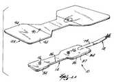
- FIG. 1is an exploded, perspective view of an integrated cable adult finger sensor including a sensor base, an optical assembly, two lenses, and a sensor cover;
- FIG. 1Ais a perspective view of the integrated cable adult finger sensor of FIG. 1 assembled and an adhesive attachment pad;
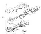
- FIG. 2is an exploded, perspective view of the integrated cable adult finger sensor of FIG. 1, viewed from the side of the sensor opposite that viewed in FIG. 1, showing the sensor cover, the two lenses, the optical assembly, and the sensor base;
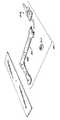
- FIG. 3is an exploded, perspective view of a detachable adult finger sensor including a sensor base, an optical assembly, two lenses, and a sensor cover;
- FIG. 3Ais a perspective view of the detachable adult finger sensor of FIG. 3 assembled and an adhesive attachment pad;
- FIG. 4is an exploded, perspective view of the detachable adult finger sensor of FIG. 3, viewed from the side of the sensor opposite that viewed in FIG. 3, showing the sensor cover, the two lenses, the optical assembly, and the sensor base;
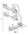
- FIG. 5is an exploded view of an integrated cable right-angle sensor for use on an infant, showing an optical assembly and the interior surfaces of a base and a cover;
- FIG. 5Ais a perspective view of the integrated cable right-angle infant sensor of FIG. 5 assembled and an adhesive attachment pad;
- FIG. 6is an exploded view of a detachable right-angle infant sensor, showing an optical assembly and the interior surfaces of a base and a cover;
- FIG. 6Ais a perspective view of the detachable right-angle infant sensor of FIG. 6 assembled and an adhesive attachment pad;
- FIG. 7is an integrated cable adult finger sensor shown in use on an adult finger.
- FIG. 8is a detachable right-angle infant sensor shown in use on an infant foot.
- FIGS. 1 through 8illustrate exploded views, taken in opposite directions, of an integrated cable adult finger sensor 10 .
- the integrated cable adult finger sensor 10includes a sensor body 14 and a sensor cable 12 (FIG. 1 A).
- the sensor body 14comprises a sensor base 18 , an optical assembly 20 , two lenses 22 , and a sensor cover 24 .
- the integrated cable adult finger sensor 10includes the sensor cable 12 affixed to the sensor body 14 as a single integrated unit (FIG. 1 A).
- the integrated cable adult finger sensor 10is affixed to a patient's finger, as shown in FIG. 7 .
- Mushroom-shaped mounting members 16 on an exterior surface 26 of the sensor base 18are inserted through apertures 90 in an adhesive pad 92 to connect the integrated cable adult finger sensor 10 to the adhesive pad 92 (FIG. 1 A).
- the integrated cable adult finger sensor 10is then folded over the fingertip of a patient and wings 94 of the adhesive pad 92 are wrapped around the patient's finger to secure the integrated cable adult finger sensor 10 in place (FIG. 7 ).
- FIGS. 1 and 2illustrate the integrated cable adult finger sensor 10 .
- FIGS. 1 and 2are also illustrative of an integrated cable pediatric finger sensor (not shown) for use on children, which differs from the integrated cable adult finger sensor 10 only in size.
- FIGS. 3, 3 A, and 4illustrate another embodiment of the present invention in the form of a detachable adult finger sensor 110 .
- the detachable adult finger sensor 110is similar to the integrated cable adult finger sensor 10 (FIGS. 1 and 2 ), except that, unlike the integrated cable adult finger sensor 10 , the sensor cable 12 is not included as an integrated part of the detachable adult finger sensor 110 . Instead, the detachable adult finger sensor 110 includes connection prongs 111 which allow it to be connected to an extension cable 113 which serves the same purpose as the sensor cable 12 integrated into the integrated cable adult finger sensor 10 .
- the detachable adult finger sensor 110allows for disposal of its sensor body 114 without requiring disposal of the reusable extension cable 113 (FIG. 3 A).
- the detachable adult finger sensor 110shown in FIGS. 3 and 4, is also illustrative of a detachable pediatric finger sensor (not shown) for use on children, which differs from the detachable adult finger sensor 110 only in size.
- FIGS. 5 and 6illustrate still additional embodiments of the present invention in the form of an integrated cable right-angle sensor 210 and a detachable right-angle sensor 310 , respectively.
- the difference between the integrated cable right-angle sensor 210 , shown in FIG. 5, and the detachable right-angle sensor 310 , shown in FIG. 6,is that the sensor body 314 of the detachable right-angle sensor 310 , shown in FIG. 6A, may be disposed of without simultaneously having to discard its extension cable 313 .
- disposal of the sensor body 214 of the integrated cable right-angle sensor 210requires disposal of the affixed sensor cable 213 .
- Right-angle sensors, as shown in FIGS. 5 and 6,are used on infants and newborns.
- finger sensorssuch as those shown in FIGS. 1 through 4 are unwieldy and impractical. Therefore, patient condition sensors are instead placed on a larger body part of an infant. As shown in FIG. 8, the detachable right-angle sensor 310 is placed on an infant's foot.
- Both the integrated cable right-angle sensor 210 , shown in FIGS. 5 and 5A, and the detachable right-angle sensor 310 , shown if FIGS. 6, 6 A and 8are for infants.
- right-angle sensors for neonatal usediffer from the right-angle sensors for infants 210 and 310 , shown in FIGS. 5, 5 A, 6 , 6 A, and 8 only in size.
- the sensor body 14includes the optical assembly 20 , two lenses 22 , and a sensor housing 15 comprising the sensor base 18 and the sensor cover 24 .
- the base 18 , optical assembly 20 , and cover 24are similarly shaped.
- the base 18includes a head portion 28 , an intermediate portion or link 30 , and a tail portion 32 .
- the optical assembly 20includes a head portion 34 , an intermediate portion or link 36 , and a tail portion 38 .
- the cover 24includes a head portion 40 , an intermediate portion or link 42 , and a tail portion 44 .
- the sensor base 18includes a channel 46 , as shown in FIG. 2, and the cover 24 includes a plateau 48 , as shown in FIG. 1 .
- the channel 46 and plateau 48are each shaped substantially like the sensor base 18 and cover 24 to include head 87 , 97 , tail 88 , 98 , and intermediate 89 , 99 portions which mate with each other to insure proper alignment and a tight fit of the base 18 and cover 24 when assembled.
- the optical assembly 20is shaped to nest within the channel 46 of the base 18 so that it too is properly aligned with the cover 24 and base 18 .
- the optical assembly 20is housed within an internal cavity of the sensor housing which is created when the plateau 48 of the cover 24 mates with the channel 46 of the sensor base 18 .
- This internal cavityincludes a head chamber, a tail chamber, and an intermediate chamber similarly shaped to, and resulting from the mating of, the head 87 , 97 , tail 88 , 98 , and intermediate 89 , 99 portions of the channel 46 and the plateau 48 .
- the internal cavity(with its head, tail, and intermediate chambers) could be formed in a one-piece housing, rather than a housing having a separate base 18 and cover 24 .
- the optical assembly 20includes a Kapton(V substrate 50 including a head portion 51 , a tail portion 55 , and an intermediate portion or link 53 , on which an LED assembly 52 , including a red emitting LED and an infrared emitting LED, and a photodetector 54 are mounted (FIG. 2 ).
- an LED assembly 52including a red emitting LED and an infrared emitting LED
- a photodetector 54are mounted
- the Kapton® substrate 50 of the optical assembly 20helps insure proper alignment of the various constituent parts.
- the head portion 34 and tail portion 38 of the optical assembly 20fit within the respective head portions 28 , 40 and tail portions 32 , 44 of the sensor base 18 and sensor cover 24 , respectively, and are wider than the intermediate portions 36 , 42 , 30 of the optical assembly 20 , cover 24 , and base 18 .
- the substrate 50 of the optical assembly 20has virtually no elasticity along its longitudinal axis 58 . Therefore, the substrate 50 serves as a “back bone” for the sensor body 14 around which the very flexible base 18 and cover 24 cannot longitudinally deform.
- the wider head portion 34 and tail portion 38 of the optical assembly 20with its longitudinally inelastic substrate 50 , prevent the sensor cover 24 and sensor base 18 from “sliding” longitudinally up and down the more narrow intermediate portion 36 of the optical assembly 20 . In this way, proper alignment of the various sensor parts is achieved and the LED assembly 52 and photodetector 54 remain positioned in line with the windows 56 in the sensor cover 24 when the sensor body 14 is assembled.
- the integrated cable adult finger sensor 10includes lugs 60 and posts 62 in the sensor base 18 (FIG. 2) which cooperate with rooms 64 and cover holes 66 in the sensor cover 24 (FIG. 1) to insure proper alignment of the base 18 relative to the cover 24 .
- the lugs 60 and posts 62also insure proper alignment of the optical assembly 20 relative to the sensor base 18 and sensor cover 24 .
- the lugs 60 in the sensor base 18fit within substrate notches 68 in the tail portion 38 of the optical assembly 20 preventing longitudinal movement of the optical assembly 20 within the channel 46 of the sensor base 18 .
- the lugs 60further mate with the rooms 64 in the sensor cover 24 when the sensor body 14 is assembled. Further, posts 62 in the sensor base 18 extend through substrate holes 70 in the head portion 34 of the optical assembly 20 and mate with the cover holes 66 in the sensor cover 24 , further preventing longitudinal misalignment of the sensor base 18 or sensor cover 24 with respect to the optical assembly 20 .
- the sensor cable 12is first threaded through an entryway 72 formed as an integral part of the sensor base 18 and out an interior aperture 74 in the base 18 (FIG. 2 ).
- wires 80 within the sensor cable 12are attached to electronic leads 76 on the substrate 50 .
- a Kevlar® strength member(not shown) within the sensor cable 12 is tied to the substrate 50 through a strengthening hole 78 in the substrate 50 so that forces acting between the optical assembly 20 and sensor cable 12 are not carried by the connection between wires 80 and electronic leads 76 , but are instead carried by the Kevlar® strength member.
- the two discrete silicon lenses 22are placed in wells 82 surrounding the windows 56 of the sensor cover 24 and are glued in place.
- the sensor cover 24with lenses 22 thus glued in place, is then positioned over the sensor base 18 , with included optical assembly 20 .
- the lugs 60 and posts 62are aligned and fitted into their respective rooms 64 and cover holes 66 , the plateau 48 is seated in the channel 46 , and a sealing ledge 25 of the cover 24 is glued to a sealing lip 19 of the base 18 .
- a seam 84is formed substantially around the outside of the resulting sensor body 14 on sidewalls 86 and 87 of the sensor body 14 , thereby providing a finished look.
- the seam 84does not extend to the entryway 72 .
- the entryway 72remains as an integral part of the sensor base 18 and has no connection seam. This lessens the possibility of delamination at the entryway 72 , which might otherwise exist if the entryway 72 were constructed of two parts with a seam between them.
- the detachable adult finger sensor 110contains various alignment and assembly features.
- the sensor body 114includes a sensor base 118 and optical assembly 120 , two lenses 122 and a sensor cover 124 .
- the sensor base 118 of the detachable adult finger sensor 110includes a channel 146 (FIG. 4) which cooperates with a plateau 148 in the sensor cover 124 (FIG. 3 ).
- the optical assembly 120is shaped to fit snuggly within the channel 146 in sensor base 118 .
- the detachable adult finger sensor 110is formed to include posts 162 (FIG. 4) which fit through substrate holes 170 and engage cover holes 166 in the sensor cover 124 (FIG. 3 ). In this way, the optical assembly is securely held between the channel 146 and the plateau 148 .
- the optical assembly 120comprises a substrate 150 on which an LED assembly 152 and photodetector 154 are mounted. Again, as with the integrated cable adult finger sensor 10 shown in FIGS. 1, 1 A and 2 , it is important that the LED assembly 152 and photodetector 154 are properly aligned with windows 156 in the sensor cover 124 . The cooperation of the posts 162 , substrate holes 170 , and cover holes 166 helps ensure this alignment. Additionally, alignment lugs 160 aid in guiding and aligning the optical assembly 120 by flanking the substrate 150 and fitting into lens wells 182 in the sensor cover 124 .
- the sensor base 118 and sensor cover 124house the entire optical assembly 120 except for connection prongs 111 formed in the substrate 150 which extend beyond the base 118 and cover 124 .
- the prongs 111fit within slots 188 to connect the sensor body 114 to the extension cable 113 in any suitable matter such as is disclosed in U.S. Pat. No. 6,061,584 to Lovejoy et al., the disclosure of which is incorporated herein by reference.
- a sensor base 218 and sensor cover 224 of the integrated cable right-angle sensor 210include similar features to the integrated cable adult finger sensor 10 shown in FIGS. 1, 1 A and 2 .
- Lugs 260 and posts 262 formed in sensor base 218cooperate with rooms 264 and cover holes 266 in sensor cover 224 and substrate notches 268 and substrate holes 270 formed in a substrate 250 to facilitate proper alignment and fit of the various assembled parts of the integrated cable right-angle sensor 210 .
- an LED assembly 252 and photodetector 254are positioned differently than in the integrated cable adult finger sensor 10 shown in FIGS. 1, 1 A and 2 .
- the LED assembly 252is positioned on a head portion 234 in the integrated cable right-angle sensor 210
- the photodetector 54is positioned on the head portion 34 in the integrated cable adult finger sensor 10 .
- the detachable right-angle sensor 310includes similar features to the detachable adult finger sensor 110 shown in FIGS. 3, 3 A and 4 , to ensure proper alignment and fit of the constituent parts of the detachable right-angle sensors 310 when assembled.
- an LED assembly 352 and photodetector 354are positioned differently than in the detachable adult finger sensor 110 shown in FIGS. 3, 3 A and 4 .
- the LED assembly 352is positioned on a head portion 334 in the detachable right-angle sensor 310
- the photodetector 154is positioned on a head portion 134 in the detachable adult finger sensor 110 .
- a channel 346 of a sensor base 318includes lugs 360 and posts 362 which cooperate with cover holes 366 and wells 382 to ensure a proper fit between the base 318 and cover 324 . Additionally, the posts 362 fit through substrate holes 370 and the lugs 360 straddle a substrate 350 of the optical assembly 320 to ensure that the optical assembly 320 is also properly aligned between the sensor base 318 and sensor cover 324 .
- the only substantial difference between the detachable right-angle sensor 310 and the integrated cable right-angle sensor 210is that the detachable right-angle 310 includes an extension arm 398 (FIG. 6A) while the integrated cable right-angle sensor 210 does not.
- the extension arm 398provides an extension to move the point of connection between the sensor body 314 and extension cable 313 away from the sight on the patient where a reading is being taken (FIG. 8 ).
- the integrated cable right-angle sensor 210does not require such an extension arm because the sensor cable 213 is integrated into the sensor body 214 , eliminating the bulky connection between the sensor body 314 and extension cable 313 found in the detachable right-angle sensor 310 .
- Each of the detachable adult finger sensor 110 , the integrated cable right-angle sensor 210 , and the detachable right-angle sensor 310includes various features which correspond to features found in the integrated cable adult finger sensor 10 , discussed above.
- the corresponding features of these various embodimentsoperate in the same way as they do with respect to the integrated cable adult finger sensor 10 .
- Each of the embodimentsensures proper fit and alignment and easy assembly of the constituent parts of the various sensor bodies.
Landscapes
- Health & Medical Sciences (AREA)
- Life Sciences & Earth Sciences (AREA)
- Physics & Mathematics (AREA)
- Medical Informatics (AREA)
- Surgery (AREA)
- Engineering & Computer Science (AREA)
- Biomedical Technology (AREA)
- Heart & Thoracic Surgery (AREA)
- Biophysics (AREA)
- Molecular Biology (AREA)
- Pathology (AREA)
- Animal Behavior & Ethology (AREA)
- General Health & Medical Sciences (AREA)
- Public Health (AREA)
- Veterinary Medicine (AREA)
- Spectroscopy & Molecular Physics (AREA)
- Optics & Photonics (AREA)
- Measurement Of The Respiration, Hearing Ability, Form, And Blood Characteristics Of Living Organisms (AREA)
Abstract
Description
Claims (32)
Priority Applications (1)
| Application Number | Priority Date | Filing Date | Title |
|---|---|---|---|
| US09/704,169US6519484B1 (en) | 2000-11-01 | 2000-11-01 | Pulse oximetry sensor |
Applications Claiming Priority (1)
| Application Number | Priority Date | Filing Date | Title |
|---|---|---|---|
| US09/704,169US6519484B1 (en) | 2000-11-01 | 2000-11-01 | Pulse oximetry sensor |
Publications (1)
| Publication Number | Publication Date |
|---|---|
| US6519484B1true US6519484B1 (en) | 2003-02-11 |
Family
ID=24828378
Family Applications (1)
| Application Number | Title | Priority Date | Filing Date |
|---|---|---|---|
| US09/704,169Expired - LifetimeUS6519484B1 (en) | 2000-11-01 | 2000-11-01 | Pulse oximetry sensor |
Country Status (1)
| Country | Link |
|---|---|
| US (1) | US6519484B1 (en) |
Cited By (84)
| Publication number | Priority date | Publication date | Assignee | Title |
|---|---|---|---|---|
| US20030156288A1 (en)* | 2002-02-20 | 2003-08-21 | Barnum P. T. | Sensor band for aligning an emitter and a detector |
| US20050197548A1 (en)* | 2004-03-05 | 2005-09-08 | Elekon Industries Usa, Inc. | Disposable/reusable flexible sensor |
| US20050277819A1 (en)* | 2002-01-08 | 2005-12-15 | Kiani Massi E | Physiological sensor combination |
| US20060000472A1 (en)* | 2001-12-31 | 2006-01-05 | Fenton Gustav R | Nasal devices including dilation and user communication and methods of using same |
| US20070032708A1 (en)* | 2005-08-08 | 2007-02-08 | Darius Eghbal | Compliant diaphragm medical sensor and technique for using the same |
| US20070073122A1 (en)* | 2005-09-29 | 2007-03-29 | Carine Hoarau | Medical sensor and technique for using the same |
| US20070123763A1 (en)* | 2005-11-29 | 2007-05-31 | Ammar Al-Ali | Optical sensor including disposable and reusable elements |
| US20080009691A1 (en)* | 1999-04-12 | 2008-01-10 | Masimo Corporation | Reusable pulse oximeter probe and disposable bandage apparatii |
| US20080081973A1 (en)* | 2006-09-28 | 2008-04-03 | Nellcor Puritan Bennett Incorporated | System and method for mitigating interference in pulse oximetry |
| WO2008039391A3 (en)* | 2006-09-22 | 2008-09-25 | Nellcor Puritan Bennett Llc | Medical sensor for reducing signal artifacts and technique for using the same |
| US7477924B2 (en) | 2006-05-02 | 2009-01-13 | Nellcor Puritan Bennett Llc | Medical sensor and technique for using the same |
| US7483731B2 (en) | 2005-09-30 | 2009-01-27 | Nellcor Puritan Bennett Llc | Medical sensor and technique for using the same |
| US7486979B2 (en) | 2005-09-30 | 2009-02-03 | Nellcor Puritan Bennett Llc | Optically aligned pulse oximetry sensor and technique for using the same |
| US7499740B2 (en) | 2004-02-25 | 2009-03-03 | Nellcor Puritan Bennett Llc | Techniques for detecting heart pulses and reducing power consumption in sensors |
| US7522948B2 (en) | 2006-05-02 | 2009-04-21 | Nellcor Puritan Bennett Llc | Medical sensor and technique for using the same |
| US7555327B2 (en) | 2005-09-30 | 2009-06-30 | Nellcor Puritan Bennett Llc | Folding medical sensor and technique for using the same |
| US7574245B2 (en) | 2006-09-27 | 2009-08-11 | Nellcor Puritan Bennett Llc | Flexible medical sensor enclosure |
| US7590439B2 (en) | 2005-08-08 | 2009-09-15 | Nellcor Puritan Bennett Llc | Bi-stable medical sensor and technique for using the same |
| US7650177B2 (en) | 2005-09-29 | 2010-01-19 | Nellcor Puritan Bennett Llc | Medical sensor for reducing motion artifacts and technique for using the same |
| US7657295B2 (en) | 2005-08-08 | 2010-02-02 | Nellcor Puritan Bennett Llc | Medical sensor and technique for using the same |
| US7658652B2 (en) | 2006-09-29 | 2010-02-09 | Nellcor Puritan Bennett Llc | Device and method for reducing crosstalk |
| US7676253B2 (en) | 2005-09-29 | 2010-03-09 | Nellcor Puritan Bennett Llc | Medical sensor and technique for using the same |
| US7680522B2 (en) | 2006-09-29 | 2010-03-16 | Nellcor Puritan Bennett Llc | Method and apparatus for detecting misapplied sensors |
| US7684842B2 (en) | 2006-09-29 | 2010-03-23 | Nellcor Puritan Bennett Llc | System and method for preventing sensor misuse |
| US20100081900A1 (en)* | 2008-09-30 | 2010-04-01 | Nellcor Puritan Bennett Llc | Medical Sensor |
| US7796403B2 (en) | 2006-09-28 | 2010-09-14 | Nellcor Puritan Bennett Llc | Means for mechanical registration and mechanical-electrical coupling of a faraday shield to a photodetector and an electrical circuit |
| US20100317936A1 (en)* | 2009-05-19 | 2010-12-16 | Masimo Corporation | Disposable components for reusable physiological sensor |
| US7869849B2 (en) | 2006-09-26 | 2011-01-11 | Nellcor Puritan Bennett Llc | Opaque, electrically nonconductive region on a medical sensor |
| US20110021893A1 (en)* | 2009-07-23 | 2011-01-27 | Oleg Gonopolskiy | Physiological sensor having a waist |
| US7880884B2 (en) | 2008-06-30 | 2011-02-01 | Nellcor Puritan Bennett Llc | System and method for coating and shielding electronic sensor components |
| US7881762B2 (en) | 2005-09-30 | 2011-02-01 | Nellcor Puritan Bennett Llc | Clip-style medical sensor and technique for using the same |
| US7887345B2 (en) | 2008-06-30 | 2011-02-15 | Nellcor Puritan Bennett Llc | Single use connector for pulse oximetry sensors |
| US7894869B2 (en) | 2007-03-09 | 2011-02-22 | Nellcor Puritan Bennett Llc | Multiple configuration medical sensor and technique for using the same |
| US20110046461A1 (en)* | 2009-08-19 | 2011-02-24 | Nellcor Puritan Bennett Llc | Nanofiber adhesives used in medical devices |
| US20110046463A1 (en)* | 2009-08-20 | 2011-02-24 | Oleg Gonopolskiy | Physiological sensor with a tail |
| US8062221B2 (en) | 2005-09-30 | 2011-11-22 | Nellcor Puritan Bennett Llc | Sensor for tissue gas detection and technique for using the same |
| US8068891B2 (en) | 2006-09-29 | 2011-11-29 | Nellcor Puritan Bennett Llc | Symmetric LED array for pulse oximetry |
| US8070508B2 (en) | 2007-12-31 | 2011-12-06 | Nellcor Puritan Bennett Llc | Method and apparatus for aligning and securing a cable strain relief |
| US8073518B2 (en) | 2006-05-02 | 2011-12-06 | Nellcor Puritan Bennett Llc | Clip-style medical sensor and technique for using the same |
| US8071935B2 (en) | 2008-06-30 | 2011-12-06 | Nellcor Puritan Bennett Llc | Optical detector with an overmolded faraday shield |
| US8092379B2 (en) | 2005-09-29 | 2012-01-10 | Nellcor Puritan Bennett Llc | Method and system for determining when to reposition a physiological sensor |
| US8092993B2 (en) | 2007-12-31 | 2012-01-10 | Nellcor Puritan Bennett Llc | Hydrogel thin film for use as a biosensor |
| USRE43169E1 (en) | 1998-10-15 | 2012-02-07 | Masimo Corporation | Universal modular pulse oximeter probe for use with reusable and disposable patient attachment devices |
| US8112375B2 (en) | 2008-03-31 | 2012-02-07 | Nellcor Puritan Bennett Llc | Wavelength selection and outlier detection in reduced rank linear models |
| US8133176B2 (en) | 1999-04-14 | 2012-03-13 | Tyco Healthcare Group Lp | Method and circuit for indicating quality and accuracy of physiological measurements |
| US8145288B2 (en) | 2006-08-22 | 2012-03-27 | Nellcor Puritan Bennett Llc | Medical sensor for reducing signal artifacts and technique for using the same |
| US8175671B2 (en) | 2006-09-22 | 2012-05-08 | Nellcor Puritan Bennett Llc | Medical sensor for reducing signal artifacts and technique for using the same |
| US8175667B2 (en) | 2006-09-29 | 2012-05-08 | Nellcor Puritan Bennett Llc | Symmetric LED array for pulse oximetry |
| US8199007B2 (en) | 2007-12-31 | 2012-06-12 | Nellcor Puritan Bennett Llc | Flex circuit snap track for a biometric sensor |
| US8219170B2 (en) | 2006-09-20 | 2012-07-10 | Nellcor Puritan Bennett Llc | System and method for practicing spectrophotometry using light emitting nanostructure devices |
| US8221319B2 (en) | 2009-03-25 | 2012-07-17 | Nellcor Puritan Bennett Llc | Medical device for assessing intravascular blood volume and technique for using the same |
| US8233954B2 (en) | 2005-09-30 | 2012-07-31 | Nellcor Puritan Bennett Llc | Mucosal sensor for the assessment of tissue and blood constituents and technique for using the same |
| US8260391B2 (en) | 2005-09-12 | 2012-09-04 | Nellcor Puritan Bennett Llc | Medical sensor for reducing motion artifacts and technique for using the same |
| US8265724B2 (en) | 2007-03-09 | 2012-09-11 | Nellcor Puritan Bennett Llc | Cancellation of light shunting |
| US8280469B2 (en) | 2007-03-09 | 2012-10-02 | Nellcor Puritan Bennett Llc | Method for detection of aberrant tissue spectra |
| US8311601B2 (en) | 2009-06-30 | 2012-11-13 | Nellcor Puritan Bennett Llc | Reflectance and/or transmissive pulse oximeter |
| USRE43860E1 (en) | 1998-10-15 | 2012-12-11 | Masimo Corporation | Reusable pulse oximeter probe and disposable bandage apparatus |
| US8346328B2 (en) | 2007-12-21 | 2013-01-01 | Covidien Lp | Medical sensor and technique for using the same |
| US8352004B2 (en) | 2007-12-21 | 2013-01-08 | Covidien Lp | Medical sensor and technique for using the same |
| US8364220B2 (en) | 2008-09-25 | 2013-01-29 | Covidien Lp | Medical sensor and technique for using the same |
| US8366613B2 (en) | 2007-12-26 | 2013-02-05 | Covidien Lp | LED drive circuit for pulse oximetry and method for using same |
| US8391941B2 (en) | 2009-07-17 | 2013-03-05 | Covidien Lp | System and method for memory switching for multiple configuration medical sensor |
| US8396527B2 (en) | 2006-09-22 | 2013-03-12 | Covidien Lp | Medical sensor for reducing signal artifacts and technique for using the same |
| US8417310B2 (en) | 2009-08-10 | 2013-04-09 | Covidien Lp | Digital switching in multi-site sensor |
| US8423112B2 (en) | 2008-09-30 | 2013-04-16 | Covidien Lp | Medical sensor and technique for using the same |
| US8433383B2 (en) | 2001-10-12 | 2013-04-30 | Covidien Lp | Stacked adhesive optical sensor |
| US8437822B2 (en) | 2008-03-28 | 2013-05-07 | Covidien Lp | System and method for estimating blood analyte concentration |
| US8442608B2 (en) | 2007-12-28 | 2013-05-14 | Covidien Lp | System and method for estimating physiological parameters by deconvolving artifacts |
| US8452366B2 (en) | 2009-03-16 | 2013-05-28 | Covidien Lp | Medical monitoring device with flexible circuitry |
| US8452364B2 (en) | 2007-12-28 | 2013-05-28 | Covidien LLP | System and method for attaching a sensor to a patient's skin |
| US8483790B2 (en) | 2002-10-18 | 2013-07-09 | Covidien Lp | Non-adhesive oximeter sensor for sensitive skin |
| US8505821B2 (en) | 2009-06-30 | 2013-08-13 | Covidien Lp | System and method for providing sensor quality assurance |
| US8509869B2 (en) | 2009-05-15 | 2013-08-13 | Covidien Lp | Method and apparatus for detecting and analyzing variations in a physiologic parameter |
| US8577434B2 (en) | 2007-12-27 | 2013-11-05 | Covidien Lp | Coaxial LED light sources |
| US8600467B2 (en) | 2006-11-29 | 2013-12-03 | Cercacor Laboratories, Inc. | Optical sensor including disposable and reusable elements |
| US8634891B2 (en) | 2009-05-20 | 2014-01-21 | Covidien Lp | Method and system for self regulation of sensor component contact pressure |
| US8649839B2 (en) | 1996-10-10 | 2014-02-11 | Covidien Lp | Motion compatible sensor for non-invasive optical blood analysis |
| US8897850B2 (en) | 2007-12-31 | 2014-11-25 | Covidien Lp | Sensor with integrated living hinge and spring |
| US8914088B2 (en) | 2008-09-30 | 2014-12-16 | Covidien Lp | Medical sensor and technique for using the same |
| US9010634B2 (en) | 2009-06-30 | 2015-04-21 | Covidien Lp | System and method for linking patient data to a patient and providing sensor quality assurance |
| US20170311473A1 (en)* | 2016-04-25 | 2017-10-26 | Asm Automation Sensorik Messtechnik Gmbh | Sensor housing |
| USD854186S1 (en)* | 2017-09-13 | 2019-07-16 | Precision Dynamics Corporation | CT gantry shield |
| US10402870B2 (en)* | 2013-11-05 | 2019-09-03 | Walmart Apollo, Llc | System and method for indicating queue characteristics of electronic terminals |
| US20210045684A1 (en)* | 2019-08-13 | 2021-02-18 | Tawaun Bell | Lower extremity diagnostic device |
Citations (6)
| Publication number | Priority date | Publication date | Assignee | Title |
|---|---|---|---|---|
| US5094240A (en)* | 1988-03-18 | 1992-03-10 | Nicolay Gmbh | Pulse/oxygen sensor and method of making |
| US5096669A (en)* | 1988-09-15 | 1992-03-17 | I-Stat Corporation | Disposable sensing device for real time fluid analysis |
| US5413099A (en)* | 1992-05-15 | 1995-05-09 | Hewlett-Packard Company | Medical sensor |
| US5429129A (en)* | 1991-08-22 | 1995-07-04 | Sensor Devices, Inc. | Apparatus for determining spectral absorption by a specific substance in a fluid |
| US5911689A (en)* | 1993-02-17 | 1999-06-15 | Utah Medical Products, Inc. | Subcutaneous radiation reflection probe |
| US6061584A (en) | 1998-10-28 | 2000-05-09 | Lovejoy; David A. | Pulse oximetry sensor |
- 2000
- 2000-11-01USUS09/704,169patent/US6519484B1/ennot_activeExpired - Lifetime
Patent Citations (6)
| Publication number | Priority date | Publication date | Assignee | Title |
|---|---|---|---|---|
| US5094240A (en)* | 1988-03-18 | 1992-03-10 | Nicolay Gmbh | Pulse/oxygen sensor and method of making |
| US5096669A (en)* | 1988-09-15 | 1992-03-17 | I-Stat Corporation | Disposable sensing device for real time fluid analysis |
| US5429129A (en)* | 1991-08-22 | 1995-07-04 | Sensor Devices, Inc. | Apparatus for determining spectral absorption by a specific substance in a fluid |
| US5413099A (en)* | 1992-05-15 | 1995-05-09 | Hewlett-Packard Company | Medical sensor |
| US5911689A (en)* | 1993-02-17 | 1999-06-15 | Utah Medical Products, Inc. | Subcutaneous radiation reflection probe |
| US6061584A (en) | 1998-10-28 | 2000-05-09 | Lovejoy; David A. | Pulse oximetry sensor |
Cited By (141)
| Publication number | Priority date | Publication date | Assignee | Title |
|---|---|---|---|---|
| US8649839B2 (en) | 1996-10-10 | 2014-02-11 | Covidien Lp | Motion compatible sensor for non-invasive optical blood analysis |
| USRE44823E1 (en) | 1998-10-15 | 2014-04-01 | Masimo Corporation | Universal modular pulse oximeter probe for use with reusable and disposable patient attachment devices |
| US8706179B2 (en) | 1998-10-15 | 2014-04-22 | Masimo Corporation | Reusable pulse oximeter probe and disposable bandage apparatii |
| USRE43169E1 (en) | 1998-10-15 | 2012-02-07 | Masimo Corporation | Universal modular pulse oximeter probe for use with reusable and disposable patient attachment devices |
| USRE43860E1 (en) | 1998-10-15 | 2012-12-11 | Masimo Corporation | Reusable pulse oximeter probe and disposable bandage apparatus |
| US20080009691A1 (en)* | 1999-04-12 | 2008-01-10 | Masimo Corporation | Reusable pulse oximeter probe and disposable bandage apparatii |
| US8175672B2 (en) | 1999-04-12 | 2012-05-08 | Masimo Corporation | Reusable pulse oximeter probe and disposable bandage apparatii |
| US8133176B2 (en) | 1999-04-14 | 2012-03-13 | Tyco Healthcare Group Lp | Method and circuit for indicating quality and accuracy of physiological measurements |
| US9265464B2 (en) | 2001-10-12 | 2016-02-23 | Covidien Lp | Stacked adhesive optical sensor |
| US8433383B2 (en) | 2001-10-12 | 2013-04-30 | Covidien Lp | Stacked adhesive optical sensor |
| US9351685B2 (en) | 2001-10-12 | 2016-05-31 | Covidien Lp | Stacked adhesive optical sensor |
| US20090000616A9 (en)* | 2001-12-31 | 2009-01-01 | Fenton Gustav R | Nasal devices including dilation and user communication and methods of using same |
| US20060000472A1 (en)* | 2001-12-31 | 2006-01-05 | Fenton Gustav R | Nasal devices including dilation and user communication and methods of using same |
| US9364181B2 (en)* | 2002-01-08 | 2016-06-14 | Masimo Corporation | Physiological sensor combination |
| US20050277819A1 (en)* | 2002-01-08 | 2005-12-15 | Kiani Massi E | Physiological sensor combination |
| US20030156288A1 (en)* | 2002-02-20 | 2003-08-21 | Barnum P. T. | Sensor band for aligning an emitter and a detector |
| US8483790B2 (en) | 2002-10-18 | 2013-07-09 | Covidien Lp | Non-adhesive oximeter sensor for sensitive skin |
| US7499740B2 (en) | 2004-02-25 | 2009-03-03 | Nellcor Puritan Bennett Llc | Techniques for detecting heart pulses and reducing power consumption in sensors |
| US20050197548A1 (en)* | 2004-03-05 | 2005-09-08 | Elekon Industries Usa, Inc. | Disposable/reusable flexible sensor |
| US7657296B2 (en) | 2005-08-08 | 2010-02-02 | Nellcor Puritan Bennett Llc | Unitary medical sensor assembly and technique for using the same |
| US7693559B2 (en) | 2005-08-08 | 2010-04-06 | Nellcor Puritan Bennett Llc | Medical sensor having a deformable region and technique for using the same |
| US7647084B2 (en) | 2005-08-08 | 2010-01-12 | Nellcor Puritan Bennett Llc | Medical sensor and technique for using the same |
| US8528185B2 (en) | 2005-08-08 | 2013-09-10 | Covidien Lp | Bi-stable medical sensor and technique for using the same |
| US7657295B2 (en) | 2005-08-08 | 2010-02-02 | Nellcor Puritan Bennett Llc | Medical sensor and technique for using the same |
| US7657294B2 (en) | 2005-08-08 | 2010-02-02 | Nellcor Puritan Bennett Llc | Compliant diaphragm medical sensor and technique for using the same |
| US20070032708A1 (en)* | 2005-08-08 | 2007-02-08 | Darius Eghbal | Compliant diaphragm medical sensor and technique for using the same |
| US8311602B2 (en) | 2005-08-08 | 2012-11-13 | Nellcor Puritan Bennett Llc | Compliant diaphragm medical sensor and technique for using the same |
| US7574244B2 (en) | 2005-08-08 | 2009-08-11 | Nellcor Puritan Bennett Llc | Compliant diaphragm medical sensor and technique for using the same |
| US7684843B2 (en) | 2005-08-08 | 2010-03-23 | Nellcor Puritan Bennett Llc | Medical sensor and technique for using the same |
| US7590439B2 (en) | 2005-08-08 | 2009-09-15 | Nellcor Puritan Bennett Llc | Bi-stable medical sensor and technique for using the same |
| US7738937B2 (en) | 2005-08-08 | 2010-06-15 | Nellcor Puritan Bennett Llc | Medical sensor and technique for using the same |
| US8260391B2 (en) | 2005-09-12 | 2012-09-04 | Nellcor Puritan Bennett Llc | Medical sensor for reducing motion artifacts and technique for using the same |
| US8600469B2 (en) | 2005-09-29 | 2013-12-03 | Covidien Lp | Medical sensor and technique for using the same |
| US7729736B2 (en) | 2005-09-29 | 2010-06-01 | Nellcor Puritan Bennett Llc | Medical sensor and technique for using the same |
| US8965473B2 (en) | 2005-09-29 | 2015-02-24 | Covidien Lp | Medical sensor for reducing motion artifacts and technique for using the same |
| US7899510B2 (en) | 2005-09-29 | 2011-03-01 | Nellcor Puritan Bennett Llc | Medical sensor and technique for using the same |
| US7676253B2 (en) | 2005-09-29 | 2010-03-09 | Nellcor Puritan Bennett Llc | Medical sensor and technique for using the same |
| US8060171B2 (en) | 2005-09-29 | 2011-11-15 | Nellcor Puritan Bennett Llc | Medical sensor for reducing motion artifacts and technique for using the same |
| US7869850B2 (en) | 2005-09-29 | 2011-01-11 | Nellcor Puritan Bennett Llc | Medical sensor for reducing motion artifacts and technique for using the same |
| US8092379B2 (en) | 2005-09-29 | 2012-01-10 | Nellcor Puritan Bennett Llc | Method and system for determining when to reposition a physiological sensor |
| US7904130B2 (en) | 2005-09-29 | 2011-03-08 | Nellcor Puritan Bennett Llc | Medical sensor and technique for using the same |
| US20070073122A1 (en)* | 2005-09-29 | 2007-03-29 | Carine Hoarau | Medical sensor and technique for using the same |
| US7650177B2 (en) | 2005-09-29 | 2010-01-19 | Nellcor Puritan Bennett Llc | Medical sensor for reducing motion artifacts and technique for using the same |
| US7555327B2 (en) | 2005-09-30 | 2009-06-30 | Nellcor Puritan Bennett Llc | Folding medical sensor and technique for using the same |
| US8352009B2 (en) | 2005-09-30 | 2013-01-08 | Covidien Lp | Medical sensor and technique for using the same |
| US8233954B2 (en) | 2005-09-30 | 2012-07-31 | Nellcor Puritan Bennett Llc | Mucosal sensor for the assessment of tissue and blood constituents and technique for using the same |
| US7881762B2 (en) | 2005-09-30 | 2011-02-01 | Nellcor Puritan Bennett Llc | Clip-style medical sensor and technique for using the same |
| US8352010B2 (en) | 2005-09-30 | 2013-01-08 | Covidien Lp | Folding medical sensor and technique for using the same |
| US8386002B2 (en) | 2005-09-30 | 2013-02-26 | Covidien Lp | Optically aligned pulse oximetry sensor and technique for using the same |
| US7483731B2 (en) | 2005-09-30 | 2009-01-27 | Nellcor Puritan Bennett Llc | Medical sensor and technique for using the same |
| US7486979B2 (en) | 2005-09-30 | 2009-02-03 | Nellcor Puritan Bennett Llc | Optically aligned pulse oximetry sensor and technique for using the same |
| US8062221B2 (en) | 2005-09-30 | 2011-11-22 | Nellcor Puritan Bennett Llc | Sensor for tissue gas detection and technique for using the same |
| US8548550B2 (en) | 2005-11-29 | 2013-10-01 | Cercacor Laboratories, Inc. | Optical sensor including disposable and reusable elements |
| WO2007064984A3 (en)* | 2005-11-29 | 2007-11-29 | Masimo Corp | Optical sensor including disposable and reusable elements |
| EP2374407A1 (en)* | 2005-11-29 | 2011-10-12 | Masimo Corporation | Optical sensor including disposable and reusable elements |
| US10420493B2 (en) | 2005-11-29 | 2019-09-24 | Masimo Corporation | Optical sensor including disposable and reusable elements |
| US20070123763A1 (en)* | 2005-11-29 | 2007-05-31 | Ammar Al-Ali | Optical sensor including disposable and reusable elements |
| US8233955B2 (en) | 2005-11-29 | 2012-07-31 | Cercacor Laboratories, Inc. | Optical sensor including disposable and reusable elements |
| US8868150B2 (en) | 2005-11-29 | 2014-10-21 | Cercacor Laboratories, Inc. | Optical sensor including disposable and reusable elements |
| US8073518B2 (en) | 2006-05-02 | 2011-12-06 | Nellcor Puritan Bennett Llc | Clip-style medical sensor and technique for using the same |
| US7477924B2 (en) | 2006-05-02 | 2009-01-13 | Nellcor Puritan Bennett Llc | Medical sensor and technique for using the same |
| US7522948B2 (en) | 2006-05-02 | 2009-04-21 | Nellcor Puritan Bennett Llc | Medical sensor and technique for using the same |
| US8437826B2 (en) | 2006-05-02 | 2013-05-07 | Covidien Lp | Clip-style medical sensor and technique for using the same |
| US8145288B2 (en) | 2006-08-22 | 2012-03-27 | Nellcor Puritan Bennett Llc | Medical sensor for reducing signal artifacts and technique for using the same |
| US8577436B2 (en) | 2006-08-22 | 2013-11-05 | Covidien Lp | Medical sensor for reducing signal artifacts and technique for using the same |
| US8219170B2 (en) | 2006-09-20 | 2012-07-10 | Nellcor Puritan Bennett Llc | System and method for practicing spectrophotometry using light emitting nanostructure devices |
| US8190224B2 (en) | 2006-09-22 | 2012-05-29 | Nellcor Puritan Bennett Llc | Medical sensor for reducing signal artifacts and technique for using the same |
| US8190225B2 (en) | 2006-09-22 | 2012-05-29 | Nellcor Puritan Bennett Llc | Medical sensor for reducing signal artifacts and technique for using the same |
| US8195264B2 (en) | 2006-09-22 | 2012-06-05 | Nellcor Puritan Bennett Llc | Medical sensor for reducing signal artifacts and technique for using the same |
| US8175671B2 (en) | 2006-09-22 | 2012-05-08 | Nellcor Puritan Bennett Llc | Medical sensor for reducing signal artifacts and technique for using the same |
| WO2008039391A3 (en)* | 2006-09-22 | 2008-09-25 | Nellcor Puritan Bennett Llc | Medical sensor for reducing signal artifacts and technique for using the same |
| US8396527B2 (en) | 2006-09-22 | 2013-03-12 | Covidien Lp | Medical sensor for reducing signal artifacts and technique for using the same |
| US7869849B2 (en) | 2006-09-26 | 2011-01-11 | Nellcor Puritan Bennett Llc | Opaque, electrically nonconductive region on a medical sensor |
| US8315685B2 (en) | 2006-09-27 | 2012-11-20 | Nellcor Puritan Bennett Llc | Flexible medical sensor enclosure |
| US7574245B2 (en) | 2006-09-27 | 2009-08-11 | Nellcor Puritan Bennett Llc | Flexible medical sensor enclosure |
| US7796403B2 (en) | 2006-09-28 | 2010-09-14 | Nellcor Puritan Bennett Llc | Means for mechanical registration and mechanical-electrical coupling of a faraday shield to a photodetector and an electrical circuit |
| US7890153B2 (en) | 2006-09-28 | 2011-02-15 | Nellcor Puritan Bennett Llc | System and method for mitigating interference in pulse oximetry |
| US8660626B2 (en) | 2006-09-28 | 2014-02-25 | Covidien Lp | System and method for mitigating interference in pulse oximetry |
| US20080081973A1 (en)* | 2006-09-28 | 2008-04-03 | Nellcor Puritan Bennett Incorporated | System and method for mitigating interference in pulse oximetry |
| US7680522B2 (en) | 2006-09-29 | 2010-03-16 | Nellcor Puritan Bennett Llc | Method and apparatus for detecting misapplied sensors |
| US8068891B2 (en) | 2006-09-29 | 2011-11-29 | Nellcor Puritan Bennett Llc | Symmetric LED array for pulse oximetry |
| US7794266B2 (en) | 2006-09-29 | 2010-09-14 | Nellcor Puritan Bennett Llc | Device and method for reducing crosstalk |
| US8175667B2 (en) | 2006-09-29 | 2012-05-08 | Nellcor Puritan Bennett Llc | Symmetric LED array for pulse oximetry |
| US7684842B2 (en) | 2006-09-29 | 2010-03-23 | Nellcor Puritan Bennett Llc | System and method for preventing sensor misuse |
| US7658652B2 (en) | 2006-09-29 | 2010-02-09 | Nellcor Puritan Bennett Llc | Device and method for reducing crosstalk |
| US9861304B2 (en) | 2006-11-29 | 2018-01-09 | Cercacor Laboratories, Inc. | Optical sensor including disposable and reusable elements |
| US9138182B2 (en) | 2006-11-29 | 2015-09-22 | Cercacor Laboratories, Inc. | Optical sensor including disposable and reusable elements |
| US8600467B2 (en) | 2006-11-29 | 2013-12-03 | Cercacor Laboratories, Inc. | Optical sensor including disposable and reusable elements |
| US10463284B2 (en) | 2006-11-29 | 2019-11-05 | Cercacor Laboratories, Inc. | Optical sensor including disposable and reusable elements |
| US8265724B2 (en) | 2007-03-09 | 2012-09-11 | Nellcor Puritan Bennett Llc | Cancellation of light shunting |
| US8280469B2 (en) | 2007-03-09 | 2012-10-02 | Nellcor Puritan Bennett Llc | Method for detection of aberrant tissue spectra |
| US7894869B2 (en) | 2007-03-09 | 2011-02-22 | Nellcor Puritan Bennett Llc | Multiple configuration medical sensor and technique for using the same |
| US8352004B2 (en) | 2007-12-21 | 2013-01-08 | Covidien Lp | Medical sensor and technique for using the same |
| US8346328B2 (en) | 2007-12-21 | 2013-01-01 | Covidien Lp | Medical sensor and technique for using the same |
| US8366613B2 (en) | 2007-12-26 | 2013-02-05 | Covidien Lp | LED drive circuit for pulse oximetry and method for using same |
| US8577434B2 (en) | 2007-12-27 | 2013-11-05 | Covidien Lp | Coaxial LED light sources |
| US8452364B2 (en) | 2007-12-28 | 2013-05-28 | Covidien LLP | System and method for attaching a sensor to a patient's skin |
| US8442608B2 (en) | 2007-12-28 | 2013-05-14 | Covidien Lp | System and method for estimating physiological parameters by deconvolving artifacts |
| US8199007B2 (en) | 2007-12-31 | 2012-06-12 | Nellcor Puritan Bennett Llc | Flex circuit snap track for a biometric sensor |
| US8092993B2 (en) | 2007-12-31 | 2012-01-10 | Nellcor Puritan Bennett Llc | Hydrogel thin film for use as a biosensor |
| US8070508B2 (en) | 2007-12-31 | 2011-12-06 | Nellcor Puritan Bennett Llc | Method and apparatus for aligning and securing a cable strain relief |
| US8897850B2 (en) | 2007-12-31 | 2014-11-25 | Covidien Lp | Sensor with integrated living hinge and spring |
| US8437822B2 (en) | 2008-03-28 | 2013-05-07 | Covidien Lp | System and method for estimating blood analyte concentration |
| US8112375B2 (en) | 2008-03-31 | 2012-02-07 | Nellcor Puritan Bennett Llc | Wavelength selection and outlier detection in reduced rank linear models |
| US7887345B2 (en) | 2008-06-30 | 2011-02-15 | Nellcor Puritan Bennett Llc | Single use connector for pulse oximetry sensors |
| US8071935B2 (en) | 2008-06-30 | 2011-12-06 | Nellcor Puritan Bennett Llc | Optical detector with an overmolded faraday shield |
| US7880884B2 (en) | 2008-06-30 | 2011-02-01 | Nellcor Puritan Bennett Llc | System and method for coating and shielding electronic sensor components |
| US8364220B2 (en) | 2008-09-25 | 2013-01-29 | Covidien Lp | Medical sensor and technique for using the same |
| US20100081900A1 (en)* | 2008-09-30 | 2010-04-01 | Nellcor Puritan Bennett Llc | Medical Sensor |
| US8914088B2 (en) | 2008-09-30 | 2014-12-16 | Covidien Lp | Medical sensor and technique for using the same |
| US8423112B2 (en) | 2008-09-30 | 2013-04-16 | Covidien Lp | Medical sensor and technique for using the same |
| US8417309B2 (en) | 2008-09-30 | 2013-04-09 | Covidien Lp | Medical sensor |
| US8452366B2 (en) | 2009-03-16 | 2013-05-28 | Covidien Lp | Medical monitoring device with flexible circuitry |
| US8221319B2 (en) | 2009-03-25 | 2012-07-17 | Nellcor Puritan Bennett Llc | Medical device for assessing intravascular blood volume and technique for using the same |
| US8509869B2 (en) | 2009-05-15 | 2013-08-13 | Covidien Lp | Method and apparatus for detecting and analyzing variations in a physiologic parameter |
| US11331042B2 (en) | 2009-05-19 | 2022-05-17 | Masimo Corporation | Disposable components for reusable physiological sensor |
| US12408869B2 (en) | 2009-05-19 | 2025-09-09 | Masimo Corporation | Disposable components for reusable physiological sensor |
| US10342487B2 (en) | 2009-05-19 | 2019-07-09 | Masimo Corporation | Disposable components for reusable physiological sensor |
| US20100317936A1 (en)* | 2009-05-19 | 2010-12-16 | Masimo Corporation | Disposable components for reusable physiological sensor |
| US8989831B2 (en) | 2009-05-19 | 2015-03-24 | Masimo Corporation | Disposable components for reusable physiological sensor |
| US9895107B2 (en) | 2009-05-19 | 2018-02-20 | Masimo Corporation | Disposable components for reusable physiological sensor |
| US8634891B2 (en) | 2009-05-20 | 2014-01-21 | Covidien Lp | Method and system for self regulation of sensor component contact pressure |
| US8311601B2 (en) | 2009-06-30 | 2012-11-13 | Nellcor Puritan Bennett Llc | Reflectance and/or transmissive pulse oximeter |
| US8505821B2 (en) | 2009-06-30 | 2013-08-13 | Covidien Lp | System and method for providing sensor quality assurance |
| US9010634B2 (en) | 2009-06-30 | 2015-04-21 | Covidien Lp | System and method for linking patient data to a patient and providing sensor quality assurance |
| US8391941B2 (en) | 2009-07-17 | 2013-03-05 | Covidien Lp | System and method for memory switching for multiple configuration medical sensor |
| US8965475B2 (en) | 2009-07-23 | 2015-02-24 | Covidien Lp | Physiological sensor having a waist |
| US20110021893A1 (en)* | 2009-07-23 | 2011-01-27 | Oleg Gonopolskiy | Physiological sensor having a waist |
| US8670812B2 (en)* | 2009-07-23 | 2014-03-11 | Covidien Lp | Physiological sensor having a waist |
| US8417310B2 (en) | 2009-08-10 | 2013-04-09 | Covidien Lp | Digital switching in multi-site sensor |
| US20110046461A1 (en)* | 2009-08-19 | 2011-02-24 | Nellcor Puritan Bennett Llc | Nanofiber adhesives used in medical devices |
| US8428675B2 (en)* | 2009-08-19 | 2013-04-23 | Covidien Lp | Nanofiber adhesives used in medical devices |
| US20110046463A1 (en)* | 2009-08-20 | 2011-02-24 | Oleg Gonopolskiy | Physiological sensor with a tail |
| US8560035B2 (en)* | 2009-08-20 | 2013-10-15 | Covidien Lp | Physiological sensor with a tail |
| US8831699B2 (en)* | 2009-08-20 | 2014-09-09 | Covidien Lp | Physiological sensor with a tail |
| US10402870B2 (en)* | 2013-11-05 | 2019-09-03 | Walmart Apollo, Llc | System and method for indicating queue characteristics of electronic terminals |
| US20170311473A1 (en)* | 2016-04-25 | 2017-10-26 | Asm Automation Sensorik Messtechnik Gmbh | Sensor housing |
| US10470328B2 (en)* | 2016-04-25 | 2019-11-05 | Asm Automation Sensorik Messtechnik Gmbh | Sensor housing |
| USD854186S1 (en)* | 2017-09-13 | 2019-07-16 | Precision Dynamics Corporation | CT gantry shield |
| US20210045684A1 (en)* | 2019-08-13 | 2021-02-18 | Tawaun Bell | Lower extremity diagnostic device |
| US11723599B2 (en)* | 2019-08-13 | 2023-08-15 | Tawaun Bell | Lower extremity diagnostic device |
Similar Documents
| Publication | Publication Date | Title |
|---|---|---|
| US6519484B1 (en) | Pulse oximetry sensor | |
| KR102555104B1 (en) | Patient Connector Assembly with Vertical Detents | |
| US5465714A (en) | Electro-optical sensor for spectrophotometric medical devices | |
| EP0959757B1 (en) | Infant/neonatal pulse oximeter sensor | |
| US20240215843A1 (en) | User-worn device for noninvasively measuring a physiological parameter of a user | |
| US6266547B1 (en) | Nasopharyngeal airway with reflectance pulse oximeter sensor | |
| US7706853B2 (en) | Near infrared spectroscopy device with reusable portion | |
| US7341559B2 (en) | Pulse oximetry ear sensor | |
| CN103200865B (en) | Disposable and removable sensors for continuous noninvasive arterial blood pressure monitoring | |
| US6505061B2 (en) | Pulse oximetry sensor with improved appendage cushion | |
| US7096052B2 (en) | Optical probe including predetermined emission wavelength based on patient type | |
| US8244325B2 (en) | Noninvasive oximetry optical sensor including disposable and reusable elements | |
| US9259185B2 (en) | Ear sensor | |
| US7280858B2 (en) | Pulse oximetry sensor | |
| US5851178A (en) | Instrumented laser diode probe connector | |
| US20020156354A1 (en) | Pulse oximetry sensor with improved spring | |
| US8251739B2 (en) | Method and apparatus for aligning and securing a cable strain relief | |
| US20100081900A1 (en) | Medical Sensor | |
| US20050228248A1 (en) | Clip-type sensor having integrated biasing and cushioning means | |
| EP1257191A1 (en) | Pacifier pulse oximeter sensor | |
| JPH1057353A (en) | Medical monitoring probe with modular device housing | |
| US20080064940A1 (en) | Sensor cable design for use with spectrophotometric sensors and method of using the same | |
| Kästle et al. | A new family of sensors for pulse oximetry | |
| WO2016135617A2 (en) | Multi-state clip-on fixation method for pulse oximeter | |
| US11678822B2 (en) | Sensor joint wrapping in a medical sensor |
Legal Events
| Date | Code | Title | Description |
|---|---|---|---|
| AS | Assignment | Owner name:GE MARQUETTE MEDICAL SYSTEMS, INC., WISCONSIN Free format text:ASSIGNMENT OF ASSIGNORS INTEREST;ASSIGNORS:LOVEJOY, DAVID ANTHONY;LANE, GEORGE ALEXANDER;REEL/FRAME:011268/0920 Effective date:20001025 | |
| AS | Assignment | Owner name:GE MARQUETTE MEDICAL SYSTEMS, INC., WISCONSIN Free format text:TO CORRECT PREVIOUS RECORDATION DUE TO THE INCORRECT NAME OF A CONVEYING PARTY ON THE RECORDATION COVER SHEET. THE ORIGINAL RECORDATION COVER SHEET AND ASSIGNMENT IS ATTACHED. THE ASSIGNMENT WAS RECORDED ON NOVEMBER 1, 2000 AT REEL 011268 AND FRAME 0920.;ASSIGNORS:LOVEJOY, DAVID ANTHONY;BYERS, GEORGE ALEXANDER;REEL/FRAME:011607/0347 Effective date:20001025 | |
| AS | Assignment | Owner name:GE MEDICAL SYSTEMS INFORMATION TECHNOLOGIES, INC., Free format text:CHANGE OF NAME;ASSIGNOR:GE MARQUETTE MEDICAL SYSTEMS, INC.;REEL/FRAME:011609/0711 Effective date:20001025 | |
| STCF | Information on status: patent grant | Free format text:PATENTED CASE | |
| CC | Certificate of correction | ||
| FEPP | Fee payment procedure | Free format text:PAYOR NUMBER ASSIGNED (ORIGINAL EVENT CODE: ASPN); ENTITY STATUS OF PATENT OWNER: LARGE ENTITY | |
| FPAY | Fee payment | Year of fee payment:4 | |
| FPAY | Fee payment | Year of fee payment:8 | |
| FPAY | Fee payment | Year of fee payment:12 |