US6519449B1 - Method and apparatus for a signal power control in a wireless communication system - Google Patents
Method and apparatus for a signal power control in a wireless communication systemDownload PDFInfo
- Publication number
- US6519449B1 US6519449B1US09/428,988US42898899AUS6519449B1US 6519449 B1US6519449 B1US 6519449B1US 42898899 AUS42898899 AUS 42898899AUS 6519449 B1US6519449 B1US 6519449B1
- Authority
- US
- United States
- Prior art keywords
- power
- signal
- station
- received
- control
- Prior art date
- Legal status (The legal status is an assumption and is not a legal conclusion. Google has not performed a legal analysis and makes no representation as to the accuracy of the status listed.)
- Expired - Lifetime
Links
- 238000000034methodMethods0.000titleclaimsabstractdescription80
- 238000004891communicationMethods0.000titleclaimsdescription26
- 238000011144upstream manufacturingMethods0.000claimsabstractdescription91
- 230000005540biological transmissionEffects0.000claimsabstractdescription35
- 230000006735deficitEffects0.000claimsabstractdescription20
- 230000007774longtermEffects0.000claimsdescription38
- 238000012935AveragingMethods0.000claimsdescription34
- 238000005070samplingMethods0.000claims2
- 230000000737periodic effectEffects0.000description20
- 238000012423maintenanceMethods0.000description13
- 230000008569processEffects0.000description13
- 230000004044responseEffects0.000description9
- 238000010586diagramMethods0.000description8
- 230000007246mechanismEffects0.000description8
- 230000007613environmental effectEffects0.000description5
- 230000001771impaired effectEffects0.000description5
- 230000001360synchronised effectEffects0.000description5
- 230000002238attenuated effectEffects0.000description3
- 230000009977dual effectEffects0.000description2
- 238000012546transferMethods0.000description2
- 230000008901benefitEffects0.000description1
- 230000001413cellular effectEffects0.000description1
- 238000013461designMethods0.000description1
- 238000005562fadingMethods0.000description1
- 230000014509gene expressionEffects0.000description1
- 238000012986modificationMethods0.000description1
- 230000004048modificationEffects0.000description1
- 230000002441reversible effectEffects0.000description1
- 238000012552reviewMethods0.000description1
Images


Classifications
- H—ELECTRICITY
- H04—ELECTRIC COMMUNICATION TECHNIQUE
- H04W—WIRELESS COMMUNICATION NETWORKS
- H04W52/00—Power management, e.g. Transmission Power Control [TPC] or power classes
- H04W52/04—Transmission power control [TPC]
- H04W52/30—Transmission power control [TPC] using constraints in the total amount of available transmission power
- H04W52/36—Transmission power control [TPC] using constraints in the total amount of available transmission power with a discrete range or set of values, e.g. step size, ramping or offsets
- H04W52/367—Power values between minimum and maximum limits, e.g. dynamic range
- H—ELECTRICITY
- H04—ELECTRIC COMMUNICATION TECHNIQUE
- H04W—WIRELESS COMMUNICATION NETWORKS
- H04W24/00—Supervisory, monitoring or testing arrangements
- H—ELECTRICITY
- H04—ELECTRIC COMMUNICATION TECHNIQUE
- H04W—WIRELESS COMMUNICATION NETWORKS
- H04W28/00—Network traffic management; Network resource management
- H04W28/16—Central resource management; Negotiation of resources or communication parameters, e.g. negotiating bandwidth or QoS [Quality of Service]
- H04W28/18—Negotiating wireless communication parameters
- H—ELECTRICITY
- H04—ELECTRIC COMMUNICATION TECHNIQUE
- H04W—WIRELESS COMMUNICATION NETWORKS
- H04W48/00—Access restriction; Network selection; Access point selection
- H04W48/08—Access restriction or access information delivery, e.g. discovery data delivery
- H—ELECTRICITY
- H04—ELECTRIC COMMUNICATION TECHNIQUE
- H04W—WIRELESS COMMUNICATION NETWORKS
- H04W52/00—Power management, e.g. Transmission Power Control [TPC] or power classes
- H04W52/04—Transmission power control [TPC]
- H04W52/06—TPC algorithms
- H04W52/08—Closed loop power control
- H—ELECTRICITY
- H04—ELECTRIC COMMUNICATION TECHNIQUE
- H04W—WIRELESS COMMUNICATION NETWORKS
- H04W52/00—Power management, e.g. Transmission Power Control [TPC] or power classes
- H04W52/04—Transmission power control [TPC]
- H04W52/06—TPC algorithms
- H04W52/16—Deriving transmission power values from another channel
- H—ELECTRICITY
- H04—ELECTRIC COMMUNICATION TECHNIQUE
- H04W—WIRELESS COMMUNICATION NETWORKS
- H04W52/00—Power management, e.g. Transmission Power Control [TPC] or power classes
- H04W52/04—Transmission power control [TPC]
- H04W52/18—TPC being performed according to specific parameters
- H04W52/22—TPC being performed according to specific parameters taking into account previous information or commands
- H04W52/225—Calculation of statistics, e.g. average or variance
Definitions
- the present inventionrelates to digital wireless communications systems and more particularly, to a method and apparatus for a signal power control in such systems.
- BWAbroadband wireless access
- a base transceiver stationBTS
- CPEcustomer premises equipment
- the BTSis usually fixed and designed with a single receiver for servicing all of the CPE units present in the cell.
- the CPE unitscan be designed to have fixed locations within the cell or alternatively be portable and free to roam.
- downstream directionthe direction of communication from the BTS to the CPE units is called the downstream direction and the reverse direction of communication is referred to as the upstream direction.
- upstream directionthe direction of communication from the BTS to the CPE units
- the datais usually multiplexed.
- multiplexing methodsused for downstream communications. For example, downstream data is often transmitted by frequency division multiple access (FDMA) by assigning a distinct downstream carrier frequency to each CPE unit.
- FDMAfrequency division multiple access
- downstream data destined for several CPE unitsis multiplexed in time and is transmitted at a common forward carrier frequency.
- Thiscan also apply to upstream communications with upstream data originating from several CPE units multiplexed in time and transmitted at another common carrier frequency.
- a cellular system that has these characteristicsis usually referred to as a time-division multiple access (TDMA) system.
- TDMAtime-division multiple access
- the time structure of a communications linkis divided into scheduling periods having a fixed number of time slots per scheduling period.
- the CPE unitscan only access the upstream link if an opportunity is granted in a scheduling period by the BTS.
- the CPE unitinitially notifies the BTS of the amount of upstream bandwidth it requires for its transmission. This bandwidth on-demand process causes upstream transmissions to occur in bursts.
- the upstream and downstream datais typically transmitted in dedicated frequency channels also referred to as radio links.
- radio link transmissionsare carried over air, channel conditions associated with radio links are much worse than those related to physical wires. Transmission impairments such as variable propagation path loss, impulse noise, fading, interference and most notably rain attenuation often occur as a result of environmental variations to corrupt and attenuate transmitted signals. These impairments dramatically reduce transmission reliability and in some situations may even cause link failures. As a result, the maintenance of reliable radio links is extremely important for a wireless system.
- a key aspect in maintaining a reliable radio link between CPE units and a BTS in a wireless systemis the ability to counteract signal power variations caused by transmission impairments.
- an automatic gain control (AGC) circuitwill generally be used in the BTS receiver to adjust the signal power received and compensate for variations caused by transmission impairments so that signals can be received at the BTS at a relatively constant power level.
- the BTS receiver AGCmust be designed to operate rapidly and on a burst-by-burst basis to efficiently service all of the CPE units present in the cell.
- AGCsare not well suited for high-frequency signals transmitted in bursts such as upstream radio signals transmitted from CPE units to a BTS.
- these burst signalstypically operate at high symbol rates in excess of 5 Megabauds with bursts of varying sizes and separated by idle periods of varying durations.
- Conventional AGCsare not suited for such high-frequency and bursty transmissions from different CPE units and would not be able to react quickly and adequately to counteract power variations in each signal burst received. Therefore, it would be desirable to provide a burst-to-burst signal power compensation scheme at the BTS to efficiently service all of the CPE units present in a cell.
- a large BTS receiver dynamic rangeis also desirable to address the well-known near-far design issue which arises as a result of large variations in propagation path loss caused by user mobility and changing distances between the CPE units and the BTS.
- transmit power controlsare used in various communications systems to help reduce the impact of transmission impairments and improve link reliability.
- a radio signal transmitted from a CPE unit to a BTSwhich is impaired or corrupted by changing environmental conditions, the signal power received at the BTS may fall outside the BTS receiver dynamic range well before the CPE transmit power can be adjusted to compensate. This is particularly true of radio signals transmitted at high frequencies which are more likely to suffer from environmental variations than low frequency signals.
- the present inventionaddresses these issues and to this end provides a methodology and apparatus to mitigate the present limitations in this art.
- the inventionprovides a signal power control method and apparatus for efficiently controlling in a wireless system the power level of a received signal transmitted over a radio link so as to counteract transmission impairments caused by environment variations and maintain the reliability of the radio link.
- the signal power control of this inventionserves to control the transmit power used for transmission and adjust the position of the receiver dynamic range so that the received signal can always be optimally received.
- the inventionis incorporated in a broadband wireless access (BWA) time division multiplex access (TDMA) system to maintain the reliability of an upstream radio link connecting a base transceiver station (BTS) with multiple customer premises equipment (CPE) units.
- BWAbroadband wireless access
- TDMAtime division multiplex access
- the signal power of upstream signals received at the BTSis controlled with two power control loops.
- a first control loopis used for adjusting the transmit power at each CPE unit and a second control loop is used to adjust the position of the BTS receiver dynamic range so that the upstream burst signals can all be received.
- each control looprelies on a communication protocol such as the international telecommunications union (ITU) R 112 local multipoint distribution service (LMSD) standard as a means to exchange power control messages between the BTS and the CPE units.
- a communication protocolsuch as the international telecommunications union (ITU) R 112 local multipoint distribution service (LMSD) standard as a means to exchange power control messages between the BTS and the CPE units.
- ITUinternational telecommunications union
- LMSDlocal multipoint distribution service
- the inventioncan effectively counteract impairments brought about by environmental changes which may afflict upstream signals during transmission.
- the upstream connectivity between the BTS and each CPE unitcan be reliably maintained.
- the inventioncan also be advantageously used for providing power control in wireless systems where receivers exhibit a narrow receive power dynamic range.
- Yet another advantage of using a CPE transmit control loop and a BTS receiver range control loopis that the received power of signals operating at high frequency and in bursts such as upstream signals in a BWA TDMA system can be efficiently controlled.
- FIG. 1is a block diagram of a typical broadband wireless access (BWA) time-division multiple access (TDMA) network featuring a base transceiver station (BTS) and multiple customer premises equipment (CPE) units;
- BWAbroadband wireless access
- TDMAtime-division multiple access
- BTSbase transceiver station
- CPEcustomer premises equipment
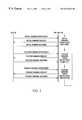
- FIG. 2is a diagram illustrating an international telecommunications union (ITU) R 112 local multipoint distribution service (LMSD) protocol (hereinafter the “R 112 protocol”) ranging process used in the BWA TDMA network of FIG. 1;
- ITUinternational telecommunications union
- LMSDlocal multipoint distribution service
- FIG. 3is a block diagram of a CPE unit and the BTS of FIG. 1 according to a preferred embodiment of the invention
- FIG. 4is a block diagram of the power estimating unit of the BTS shown in FIG. 3;
- FIG. 5is a block diagram of the control unit of the BTS shown in FIG. 3;
- FIG. 6is a block diagram of the power adjusting unit of the CPE unit shown in FIG. 3;
- FIG. 7is a flow chart illustrating a power control operation sequence during the R 112 initial ranging procedure according to the preferred embodiment of the invention.
- FIG. 8is a flow chart illustrating a power control operation sequence during the R 112 station ranging procedure according to the preferred embodiment of the invention.
- FIG. 9is a flow chart illustrating a power control operation sequence during the R 112 periodic ranging procedure according to the preferred embodiment of the invention.
- the inventionprovides a signal power control method and apparatus for efficiently controlling in a wireless system the power level of a received signal transmitted over a radio link so as to counteract transmission impairments caused by environment variations and maintain the reliability of the radio link.
- the signal power control of this inventionserves to control the transmit power used for transmission and adjust the position of the receiver dynamic range so that the received signal can be optimally received.
- the inventionis incorporated in a broadband wireless access (.BWA) time-division multiple access (TDMA) network to provide a fast and efficient power control for upstream transmissions between a base transceiver station (BTS) and multiple customer premises equipment (CPE) units.
- .BWAbroadband wireless access
- TDMAtime-division multiple access
- FIG. 1there is illustrated a block diagram of a BWA TDMA network generally indicated by 10 which consists of a BTS 30 connected to a plurality N of CPE units 40 , 50 , 60 (only three shown) via an upstream radio frequency link 12 and a downstream radio link 14 .
- the BTS 30has a transmitter 32 operable to transmit downstream data over the downstream radio link 14 and each of the CPE units 40 , 50 , 60 has a respective receiver 44 , 54 , 64 tuned to receive the downstream data transmitted by the BTS 30 .
- the CPE units 40 , 50 , 60have a respective transmitter 42 , 52 , 62 operable to transmit upstream data over the upstream radio link 12 and the BTS 30 has a receiver 34 of a defined dynamic range which can receive the upstream data transmitted from the CPE units 40 , 50 , 60 .
- each particular CPE unit 40 , 50 , 60must be synchronized with the BTS 30 .
- the BWA TDMA network 10uses a communication protocol which defines a synchronization or ranging process by which a CPE unit 40 , 50 , 60 can initially and periodically thereafter synchronize itself with the BTS 30 for upstream communications.
- the signal power received at the BTS 30 for each upstream signal transmitted by the CPE units 40 , 50 , 60is closely controlled to counteract transmission impairments and maintain the upstream link 12 reliable.
- the signal power of each upstream signal received at the BTS 30must be maintained within the BTS receiver dynamic range.
- the inventionprovides a transmit power control to adjust the transmit power used at each CPE unit 40 , 50 , 60 and a receiver range control to shift the position of the BTS receiver dynamic range to a location where all the upstream signals can be received.
- the BTS 30can rapidly and efficiently adjust the power of each received upstream signal on an individual basis. In this way, the received power of an upstream signal impaired or attenuated more than other upstream signals can be independently compensated without altering the signal power received on the other upstream signals which may not be impaired or attenuated to the same extent.
- the BTS 30controls the transmit power used at each CPE unit 40 , 50 , 60 by way of a transmitter (Tx) power control loop.
- Txtransmitter
- the BTS receiverinstructs the transmitting CPE unit 40 , 50 , 60 to adjust its transmit power such that the signal power received at the BTS receiver can be maintained at the optimal level.
- This transmit power controlprovides short-term adjustment of the upstream signal power receiver at the BTS 30 .
- the BTS 30can shift the BTS receiver dynamic range.
- the dynamic range limitation of the BTS receiveris used as a window that can be moved within the total range of the receiver to ensure that all the upstream signals can be received within the BTS receiver dynamic range.
- the BTS receiver dynamic range controlis also performed by way of a receiver (Rx) range control loop at the BTS 30 .
- the BTS receiver range controlis particularly useful in situations where all of the upstream signals are subject to the same transmission impairments such as for example, a rainfall over the cell in which the BWA TDMA network 10 is located. In these situations, all of the upstream signals would be subject to similar transmission impairments and be relatively impaired or attenuated at the same rate.
- the upstream signalscan be collectively compensated by the BTS 30 which can shift the BTS receiver dynamic range to a position where all of the upstream signals can be received.
- This BTS receiver dynamic range controlcan be viewed as a long-term power control.
- the BTS 30relies on the existing communication protocol used in the BWA TDMA network 10 to exchange power control messages with the CPE units 40 , 50 , 60 .
- ITUinternational telecommunications union
- LMSDlocal multipoint distribution service
- each particular CPE unit 40 , 50 , 60must be synchronized with the BTS 30 .
- the BWA TDMA network 10uses the R 112 communication protocol which defines a synchronization (ranging) process by which a new CPE unit 40 , 50 , 60 can initially and continuously thereafter synchronize itself with the BTS 30 for upstream communications.
- the BTS 30runs periodical checks to see if there is any new CPE unit 40 , 50 , 60 which has been powered up and is about to join the BWA TDMA network 10 . For this, the BTS provides ranging opportunities for new CPE units 40 , 50 , 60 , to join the BWA TDMA network 10 .
- the BTS 30receives an initial ranging request from a new CPE unit 40 , 50 , 60
- the BTS 30initiates a ranging process to synchronize the new PCE unit 40 , 50 , 60 with the BTS 30 .
- FIG. 2illustrates a R 112 ranging process in detail.
- the ranging process shown in this figureconsists of an initial ranging procedure, a station ranging procedure and a periodic ranging procedure.
- messagesare exchanged between the new CPE unit 40 , 50 , 60 and the BTS 30 to carry out the synchronization.
- the initial ranging procedureis initiated as the BTS receives an initial ranging request from a new CPE unit 40 , 50 , 60 .
- the BTS 30invites the new CPE unit 40 , 50 , 60 for an initial station maintenance.
- the BTS 30requests the new CPE unit 40 , 50 , 60 to nominally adjust its local timing base, upstream carrier frequency and upstream transmit power for TDMA operations over the upstream radio link 14 .
- the BTS 30transmits an initial ranging opportunity message to the new CPE unit 40 , 50 , 60 to schedule an initial maintenance period on the upstream radio link 12 .
- the new CPE unit 40 , 50 , 60transmits an initial ranging request message to the BTS 30 .
- the initial ranging request message received from the new CPE unit 40 , 50 , 60is used to measure and estimate nominal timing, frequency and power offsets for the new CPE unit 40 , 50 , 60 .
- the offsets calculatedare transmitted to the new CPE unit 40 , 50 , 60 in the form of an initial ranging response message.
- the offsets receivedare applied so that the new CPE unit 40 , 50 , 60 can be nominally synchronized to the BTS 30 .
- the BTS 30After this initial station maintenance, the BTS 30 enters into the station ranging procedure to further adjust the CPE local timing base, upstream carrier frequency and transmit power. Similarly to the initial station maintenance, three messages are also exchanged during the course of this ranging procedure. First, the BTS 30 transmits a station ranging opportunity message to the new CPE unit 40 , 50 , 60 to schedule a station maintenance period. Upon receiving the station ranging opportunity message, the new CPE unit 40 , 50 , 60 transmits a station ranging request message to the BTS 30 . Similarly, at the BTS 30 , the station ranging request message is used to measure and estimate the CPE local timing base, upstream carrier frequency and upstream transmit power offsets.
- the adjustmentsare transmitted to the new CPE unit 40 , 50 , 60 in the form of a station ranging response message and applied therein to better synchronize the new CPE unit 40 , 50 , 60 to the BTS 30 .
- the station ranging procedureis a fine adjustment procedure and may be repeated many times if necessary.
- the new CPE unit 40 , 50 , 60can begin to exchange upstream data with the BTS 30 via the upstream link 12 .
- the BTS 30In order to maintain synchronization of the new CPE unit 40 , 50 , 60 with the BTS 30 , the BTS 30 periodically enters into the periodic ranging procedure to periodically adjust of the TDMA timing, upstream carrier frequency and transmit power if necessary. Similarly to the initial station procedure and the station ranging procedure, three messages are also exchanged during the course of this periodic ranging procedure.
- the BTS 30transmits a periodic ranging opportunity message to the new CPE unit 40 , 50 , 60 to schedule a periodic ranging maintenance period.
- the new CPE unit 40 , 50 , 60transmits a periodic ranging request message to the BTS 30 .
- the periodic ranging request messageis used to periodically adjust the CPE local timing base, upstream carrier frequency and upstream transmit power offsets.
- the adjustmentsare transmitted to the new CPE unit 40 , 50 , 60 in the form of a periodic ranging response message and applied therein to better synchronize the new CPE unit 40 , 50 , 60 to the BTS 30 .
- the periodic ranging procedureis repeated periodically until the upstream link 12 fails to continuously synchronize the new CPE unit 40 , 50 , 60 to the BTS 30 . If the upstream link 12 fails, the BTS 30 returns to the initial ranging procedure to re-synchronize the new CPE unit 40 , 50 , 60 .
- the R 112 protocolis used to execute the ranging process and synchronize the CPE units 40 , 50 , 60 . It will be recalled that as part of the ranging process, the signal power received at the BTS 30 for each upstream.signal is controlled with a CPE Tx transmit power control loop and the BTS receiver dynamic range is also controlled with a Rx range control loop. According to the invention, each control loop uses the R 112 protocol as a means to exchange power control messages between the BTS 30 and the CPE units 40 , 50 , 60 for implementing both the CPE transmit control and the BTS range control.
- This dual power control mechanismeffectively counteracts transmission impairments caused by environmental changes which may affect upstream signals transmitted by the CPE units 40 , 50 , 60 .
- upstream connectivity between the BTS 30 and each CPE unit 40 , 50 , 60can be more reliably maintained.
- CPE transmit power control and BTS receiver range adjustmentas implemented in the BWA TDMA network 10 and more particularly as implemented in the BTS 30 and the CPE units 40 , 50 , 60 .
- the architecture and functionality necessary in each of the CPE units 40 , 50 , 60is identical and, except as otherwise noted below, is only be described with reference to the CPE unit 40 . It is to be understood however that this description is also equally applicable to the CPE units 50 and 60 .
- FIG. 3there is illustrated a more detailed block diagram of the architecture and functionality necessary to implement the CPE transmit power control and the BTS receiver range control in the CPE unit 40 and the BTS 30 .
- this dual control mechanismit will be recalled that two control loops are used. More specifically, a Tx power control loop is used to implement the CPE transmit power control mechanism and a Rx range control loop is used to implement the BTS receiver range control. With these two control loops, a transmit power control for the CPE unit 40 and a BTS receiver range control for the BTS 30 can be implemented to provide the necessary power control to counteract transmission impairments and ensure the reliability of the upstream connection between the BTS 30 and the CPE unit 40 .
- the Rx range control loopis internal to the BTS unit and is formed of the BTS receiver 34 , a power estimating unit 36 and a control unit 38 . More specifically, the BTS 30 has its receiver 34 internally connected to the power estimating unit 36 which is in turn connected to the control unit 38 . The control unit 38 is coupled to the BTS transmitter 32 but is also connected back to the BTS receiver 34 to complete the Rx range control loop.
- the Tx power control loopis formed of the same BTS components but also includes the CPE unit 40 . More specifically, the Tx power control loop is formed of the BTS receiver 34 , the power estimating unit 36 and the control unit 38 all connected in series with the BTS transmitter 32 . At the BTS transmitter 32 , the Tx power control loop extends over to the CPE unit 40 via the downstream radio link 14 to include the CPE receiver 44 , a power adjusting unit 46 and the CPE transmitter 42 all connected in series. The Tx power control loop is completed with the CPE transmitter 42 connected back to the BTS receiver 34 via the upstream radio link 12 .
- the BTS receiver 34receives the upstream signals transmitted from the CPE units 40 , 50 , 60 and operates to produce a mixed power sample sequence for the power estimating unit 36 .
- the mixed power sample sequencecontains interleaved power samples received from the CPE units 40 , 50 , 60 .
- the power estimating unit 36receives the mixed power sample sequence from the BTS receiver 34 and computes short-term and long-term power averages for each CPE unit 40 , 50 , 60 .
- the short-term power averagesare processed to determine whether the CPE transmit power used in each CPE unit 40 , 50 , 60 must be adjusted.
- the long-term power averagesare processed to adjust the BTS receive power window position optimally.
- FIG. 4illustrates in more detail the power estimating unit 36 shown in FIG. 3 .
- the power estimating unit 36includes a 1:N demultiplexer 100 connected externally to the BTS receiver 34 (see FIG. 3) to receive the mixed power sample sequence.
- the 1:N demultiplexer 100is connected to both a short-term averaging unit 102 and a long-term averaging unit 104 in parallel to produce thereto N power sample subsequences T 1 , 2 , T N each corresponding to a particular CPE unit 40 , 50 , 60 .
- the short-term averaging unit 102Based on the N power subsequences T 1 , T 2 , T N , the short-term averaging unit 102 produces N short-term power averages S 1 , S 2 , S N each corresponding to a particular CPE unit 40 , 50 , 60 .
- the long-term averaging unit 104produces N long-term power averages L 1 , L 2 , L N each corresponding to a particular CPE unit 40 , 50 , 60 .
- the short-term averaging unit 102calculates a short-term power average for a specified number of power samples received defining a short-term averaging window.
- T i (n)represents a power sample received from the CPE unit i at the n th ranging period and K is the normalized width of the short-term averaging window.
- the short-term power averages S 1 , S 2 , S N calculated for the CPE units 40 , 50 , 60are used in the control unit 38 to determine a CPE transmit control power offset for each particular CPE unit 40 , 50 , 60 .
- the long-term averaging unit 104calculates for each CPE unit 40 , 50 , 60 a long-term power average for another (larger) specified number of power samples received defining a long-term averaging window.
- T i (n)represents a power sample received from the CPE unit i at the n th ranging period and M is the normalized width of the long-term averaging window.
- the long-term power averages L 1 , L 2 , L N calculatedare forwarded to the control unit 38 to produce a power threshold for two purposes.
- the power thresholdis used to determine the CPE transmit control power offsets for the CPE units 40 , 50 , 60 .
- the second purpose for which the power threshold is producedis to determine an adjustment for the BTS receiver range window position.
- FIG. 5illustrates in more detail the control unit 38 of FIG. 3 .
- the control unit 38has a comparator 110 connected to receive the short-term power averages S 1 , S 2 , S N from the estimating unit 36 to produce N CPE transmit control power offsets each for a particular CPE unit 40 , 50 , 60 .
- the N CPE transmit power offsetsare multiplexed by a multiplexer 112 into a Tx power offset sequence and forwarded to the BTS transmitter 32 for transmission to the CPE units 40 , 50 , 60 via the downstream radio link 14 .
- the control unitalso has a Rx range estimator 114 connected to receive the long-term power averages L 1 , L 2 , L N from the estimating unit 36 to produce a power threshold against which the short-term power average S 1 , S 2 , S N are compared to produce the N CPE transmit power offsets.
- the CPE transmit power offsets producedare then multiplexed by the multiplexer 112 into a Tx power offset sequence so that they can be transmitted to the CPE units 40 , 50 , 60 via the BTS transmitter 32 .
- the control unit 38also has a control signal generator 118 connected to receive the power threshold produced by the Rx range estimator 114 through a quantizer 116 .
- the control signal generator 118produces a control signal to the BTS receiver 34 for adjusting the BTS receiver range window position.
- the short-term power averages S 1 , S 2 , S N calculated in the power estimating unit 36are used in the control unit 38 to determine a CPE transmit control power offset for each particular CPE unit 40 , 50 , 60 .
- the short-term power averages S 1 , S 2 , S Nare each compared in the comparator 110 to the power threshold generated by Rx range estimator 114 to produce a respective CPE transmit power offset.
- the comparator 110produces a resulting power offset ⁇ P i (n) which can be expressed as follows:
- Ref(n)represents the power threshold produced by the Rx range estimator 114 .
- the power threshold Ref(n) produced by the Rx range estimator 114is a function of all of the long-term power averages L 1 (n), L 2 (n) L N (n) produced.
- the power threshold Ref(n)can be generally expressed as:
- Ref ( n )f ( L 1 ( n ), L 2 ( n ) L N ( n ))
- the power threshold Ref(n)is a measure of the average power received from all of the CPE units 40 , 50 , 60 . According to the invention, the manner in which Ref(n) is calculated as a function of L 1 (n), L 2 (n) and L N (n) for determining the CPE transmit power offsets and the optimal position for the BTS receiver range window is not unique.
- the CPE transmit power offsets produced in the comparator 110are multiplexed by the multiplexer 112 into a Tx power offset sequence so that they can be transmitted to the CPE units 40 , 50 , 60 via the BTS transmitter 32 .
- the corresponding CPE transmit power offsetis retrieved and applied therein.
- the architecture and functionality required in each CPE unit 40 , 50 , 60 to receive and apply the CPE transmit power offsetsis identical and will now be described with reference to FIG. 6 only in relation to the CPE unit 40 .
- the CPE unit 40has connected between the CPE receiver 44 and the CPE transmitter 42 a quantizer 120 connected in series with a control signal generator 122 .
- the CPE receiver 44operates to retrieve from the Tx sequence the CPE transmit power offset intended for the CPE unit 40 .
- the CPE transmit power offset retrievedis quantized in the quantizer 120 .
- the quantizer 120produces a resulting quantized CPE transmit offset ⁇ T i (n) which can be expressed as follows:
- this quantized CPE transmit offset ⁇ Tx i (n)can be used in the control signal generator 122 to generate the appropriate control signal for adjusting the CPE transmit power used in the CPE transmitter 42 for the next ranging period:
- Tx i ( n +1)Tx i ( n )+ ⁇ Tx i ( n )
- the power threshold Ref(n)is also used in the control unit 38 to determine an adjustment for the BTS receiver range window position.
- the power threshold Ref(n)is quantized in the quantizing unit 116 to produce a quantized output RW(n) which can be generally expressed as follows:
- control signal generator 118can generate the appropriate control signal for adjusting the BTS receiver range window position.
- the BTS 30relies on the R 112 protocol to obtain power samples from the CPE units 40 , 50 , 60 and transmit CPE transmit power offsets to the CPE units 40 , 50 , 60 .
- These transactionstake the form of control messages which are exchanged during the ranging process of each-CPE unit 40 , 50 , 60 .
- the R 112 ranging processconsists of an initial ranging procedure, a station ranging procedure and a periodic ranging procedure.
- the BTS 30exchanges power control messages with each CPE unit 40 , 50 , 60 to monitor the upstream power received from each CPE unit 40 , 50 , 60 and adjust the CPE transmit power and the BTS receiver power range window position accordingly.
- FIG. 7there is illustrated a flow chart of the power control operation sequence during the R 112 initial ranging procedure of the CPE unit 40 .
- the BTS 30broadcasts a traffic control message (TCM) to the CPE unit 40 to schedule an initial maintenance period on the upstream radio link 12 .
- TCMtraffic control message
- the CPE unit 40transmits an initial power control request message to the BTS 30 .
- the initial power control request messageis used to estimate the upstream power received and compute a nominal upstream transmit power offset for the CPE unit 40 based on the upstream power received estimate without any short-term or long term averaging.
- the offset calculatedis then transmitted to the CPE unit 40 in the form of an initial power control response message.
- the offset receivedis applied in the manner described above so that the CPE transmit power can be nominally adjusted.
- the transmit power used by the CPE unit 40is not adequate.
- the power control request message sent by the CPE unit 40may not be received by the BTS 30 and the BTS 30 may not issue a power control response message. If the CPE unit 40 does not receive any power control response message within a specified time period, the CPE unit 40 will adjust its transmit power and wait for the next initial maintenance opportunity after a random back off time elapses to re-transmit its power control request.
- the CPE unit 40is in a position to nominally communicate with the BTS 30 .
- the BTS 30enters into the station ranging procedure.
- FIG. 8illustrates the power control operation sequence during the R 112 station ranging procedure for the CPE unit 40 .
- the BTSadds the CPE unit 40 , 50 , 60 to its station ranging poll list and sends a TCM message to the CPE unit 40 to schedule a station maintenance period.
- the CPE unit 40transmits a station power control request message to the BTS 30 .
- the station power control request messageis used to estimate the upstream power received and compute another upstream transmit power offset for the CPE unit 40 based on short-term averaging of the upstream power received.
- the offset calculatedis then transmitted to the CPE unit 40 in the form of a station power control response message.
- the offset receivedis applied in the manner described above so that the CPE transmit power can be finely adjusted.
- this fine adjustment processis repeated until the upstream power received at the BTS 30 falls at an optimum point within the BTS receiver dynamic range. More specifically, the BTS 30 may continue to issue TCM messages to receive additional station power control requests from the CPE unit 40 . As it receives additional requests, the BTS 30 can compute other upstream transmit power offsets for the CPE unit 40 based on further short-term averaging of the upstream power received. According to the invention, new transmit power offsets will be transmitted to the CPE unit 40 and applied therein until the upstream power transmitted can be optimally received at the BTS 30 .
- the BTSremoves the CPE unit 40 from its BTS poll list and the CPE unit 40 enters a data transfer CPE registration procedure to enable upstream data transfers to the BTS 30 .
- the CPE transmit power control procedurecan also be aborted in which case the BTS 30 would revert back to the initial ranging procedure described above.
- the CPE unit 40can begin to send upstream data to the BTS 30 via the upstream link 12 .
- the inventionuses the R 112 periodic ranging procedure to continuously monitor and adjust the CPE transmit power and the BTS receiver range window.
- the BTS 30transmits a TCM message to the CPE unit 40 to schedule a periodic ranging maintenance period.
- the CPE unit 40Upon receiving the TCM message, the CPE unit 40 transmits a periodic power control request message to the BTS 30 .
- the periodic power control request messageis used to estimate the upstream power received and compute an upstream transmit power offset.
- the transmit power offsetis calculated by first short-term averaging the upstream power received from the CPE unit 40 .
- the BTSlong-term averages the upstream power received from each CPE unit 40 , 50 , 60 (and not just the CPE unit 40 ) to produce a power threshold.
- the transmit power offsetis calculated comparing the short-term average obtained to the power threshold.
- the power thresholdis also used to shift the BTS receiver range window to a location where all of the upstream signals transmitted by the CPE units 40 , 50 , 60 can be optimally received.
- the BTS receiver range window positionis then shifted based on the power threshold calculated and the transmit power offset calculated is transmitted to the CPE unit 40 in the form of a periodic power control response message.
- the offset receivedis applied in the manner described above so that the CPE transmit power can be adjusted.
- the BTSremoves the CPE unit 40 from its periodic poll list until the next periodic ranging procedure. This control adjustment procedure is repeated periodically until the upstream link 12 fails. If the upstream link 12 fails, the BTS 30 returns return back to the initial ranging procedure described above.
- the inventionhas been described in relation to a BWA TDMA network. It is to be understood that the invention is also applicable to other types of BWA networks. Also, the invention is not restricted to upstream transmissions from a plurality of CPE units to a BTS and could also apply to downstream transmissions from the BTS to the CPE units.
- the inventionis applicable to any wireless network or system in which a signal is transmitted from one station to another station provided the transmit power used for transmitting the signal and the receiving station dynamic range can be both controlled in accordance with the principles described therein.
Landscapes
- Engineering & Computer Science (AREA)
- Computer Networks & Wireless Communication (AREA)
- Signal Processing (AREA)
- Mobile Radio Communication Systems (AREA)
Abstract
Description


Claims (39)
Priority Applications (1)
| Application Number | Priority Date | Filing Date | Title |
|---|---|---|---|
| US09/428,988US6519449B1 (en) | 1999-10-29 | 1999-10-29 | Method and apparatus for a signal power control in a wireless communication system |
Applications Claiming Priority (1)
| Application Number | Priority Date | Filing Date | Title |
|---|---|---|---|
| US09/428,988US6519449B1 (en) | 1999-10-29 | 1999-10-29 | Method and apparatus for a signal power control in a wireless communication system |
Publications (1)
| Publication Number | Publication Date |
|---|---|
| US6519449B1true US6519449B1 (en) | 2003-02-11 |
Family
ID=23701283
Family Applications (1)
| Application Number | Title | Priority Date | Filing Date |
|---|---|---|---|
| US09/428,988Expired - LifetimeUS6519449B1 (en) | 1999-10-29 | 1999-10-29 | Method and apparatus for a signal power control in a wireless communication system |
Country Status (1)
| Country | Link |
|---|---|
| US (1) | US6519449B1 (en) |
Cited By (72)
| Publication number | Priority date | Publication date | Assignee | Title |
|---|---|---|---|---|
| US20020123364A1 (en)* | 2001-02-12 | 2002-09-05 | Francesco Palmeri | Method for controlling the signal level from terminals to a node in a network in point to multi-point radio-communication systems having time division multiple access |
| US20030199284A1 (en)* | 2002-04-19 | 2003-10-23 | Christiansen Robert D. | Mobile device power modulation for detecting imaging device proximity |
| US20040006771A1 (en)* | 2002-07-02 | 2004-01-08 | Broadcom Corporation | Modified range requests enabling bandwidth requests and state of health reporting |
| US20040203968A1 (en)* | 2002-06-28 | 2004-10-14 | Nandu Gopalakrishnan | Method of uplink scheduling for data communication |
| US6877166B1 (en)* | 2000-01-18 | 2005-04-05 | Cisco Technology, Inc. | Intelligent power level adjustment for cable modems in presence of noise |
| US20050197171A1 (en)* | 2004-03-05 | 2005-09-08 | Samsung Electronics Co., Ltd. | System and method for periodic ranging in sleep mode in broadband wireless access communication system |
| WO2005088853A1 (en)* | 2004-03-09 | 2005-09-22 | Neocific Inc. | Methods and apparatus for random access in multi-carrier communication systems |
| US20050266896A1 (en)* | 2004-05-07 | 2005-12-01 | Samsung Electronics Co., Ltd. | System and method for periodic ranging in a sleep mode in a BWA communication system |
| WO2005060358A3 (en)* | 2003-12-22 | 2006-02-09 | Korea Electronics Telecomm | An apparatus and method for power saving in a subscriber station |
| KR100590584B1 (en) | 2004-03-16 | 2006-06-19 | 에스케이 텔레콤주식회사 | Transmission Power Control Method by Open-loop Automatic Gain Control in Broadband Wireless Access Networks |
| US20060182021A1 (en)* | 2003-01-31 | 2006-08-17 | Kristensen Tommy B | Output power control in multislot uplinks |
| WO2006016765A3 (en)* | 2004-08-09 | 2007-04-05 | Lg Electronics Inc | Periodic ranging in a wireless access system for mobile station in sleep mode |
| US20080137562A1 (en)* | 2004-05-01 | 2008-06-12 | Neocific, Inc. | Methods And Apparatus For Communication With Time-Division Duplexing |
| US20090219852A1 (en)* | 2005-11-11 | 2009-09-03 | Youn Ae Ran | Method of controlling relay communication |
| US20100184446A1 (en)* | 2009-01-20 | 2010-07-22 | Samsung Electronics Co., Ltd. | Apparatus and method for adjusting offset in a wireless communication system |
| US20100272066A1 (en)* | 2009-04-23 | 2010-10-28 | Interdigital Patent Holdings, Inc. | Base station assistance for random access performance improvement |
| US20110009156A1 (en)* | 2008-03-05 | 2011-01-13 | Telefonaktiebolaget L M Ericsson (Publ) | Wireless communication power control |
| CN101964679A (en)* | 2010-10-09 | 2011-02-02 | 杭州华三通信技术有限公司 | Ethernet over Coax equipment power control method and device thereof |
| USRE43308E1 (en)* | 1999-11-23 | 2012-04-10 | Auctnyc 7 Llc | Adjustment of period of real-time slow drift correction of alignment of handset's local oscillator for a cordless telephone |
| US8532492B2 (en) | 2009-02-03 | 2013-09-10 | Corning Cable Systems Llc | Optical fiber-based distributed antenna systems, components, and related methods for calibration thereof |
| US8639121B2 (en) | 2009-11-13 | 2014-01-28 | Corning Cable Systems Llc | Radio-over-fiber (RoF) system for protocol-independent wired and/or wireless communication |
| US8644844B2 (en) | 2007-12-20 | 2014-02-04 | Corning Mobileaccess Ltd. | Extending outdoor location based services and applications into enclosed areas |
| US8718478B2 (en) | 2007-10-12 | 2014-05-06 | Corning Cable Systems Llc | Hybrid wireless/wired RoF transponder and hybrid RoF communication system using same |
| US8831428B2 (en) | 2010-02-15 | 2014-09-09 | Corning Optical Communications LLC | Dynamic cell bonding (DCB) for radio-over-fiber (RoF)-based networks and communication systems and related methods |
| US8867919B2 (en) | 2007-07-24 | 2014-10-21 | Corning Cable Systems Llc | Multi-port accumulator for radio-over-fiber (RoF) wireless picocellular systems |
| US8873585B2 (en) | 2006-12-19 | 2014-10-28 | Corning Optical Communications Wireless Ltd | Distributed antenna system for MIMO technologies |
| US8983301B2 (en) | 2010-03-31 | 2015-03-17 | Corning Optical Communications LLC | Localization services in optical fiber-based distributed communications components and systems, and related methods |
| US9158864B2 (en) | 2012-12-21 | 2015-10-13 | Corning Optical Communications Wireless Ltd | Systems, methods, and devices for documenting a location of installed equipment |
| US9178635B2 (en) | 2014-01-03 | 2015-11-03 | Corning Optical Communications Wireless Ltd | Separation of communication signal sub-bands in distributed antenna systems (DASs) to reduce interference |
| US9185674B2 (en) | 2010-08-09 | 2015-11-10 | Corning Cable Systems Llc | Apparatuses, systems, and methods for determining location of a mobile device(s) in a distributed antenna system(s) |
| US9184843B2 (en) | 2011-04-29 | 2015-11-10 | Corning Optical Communications LLC | Determining propagation delay of communications in distributed antenna systems, and related components, systems, and methods |
| US9240835B2 (en) | 2011-04-29 | 2016-01-19 | Corning Optical Communications LLC | Systems, methods, and devices for increasing radio frequency (RF) power in distributed antenna systems |
| US9247543B2 (en) | 2013-07-23 | 2016-01-26 | Corning Optical Communications Wireless Ltd | Monitoring non-supported wireless spectrum within coverage areas of distributed antenna systems (DASs) |
| US9258052B2 (en) | 2012-03-30 | 2016-02-09 | Corning Optical Communications LLC | Reducing location-dependent interference in distributed antenna systems operating in multiple-input, multiple-output (MIMO) configuration, and related components, systems, and methods |
| US9357551B2 (en) | 2014-05-30 | 2016-05-31 | Corning Optical Communications Wireless Ltd | Systems and methods for simultaneous sampling of serial digital data streams from multiple analog-to-digital converters (ADCS), including in distributed antenna systems |
| US9385810B2 (en) | 2013-09-30 | 2016-07-05 | Corning Optical Communications Wireless Ltd | Connection mapping in distributed communication systems |
| US9420542B2 (en) | 2014-09-25 | 2016-08-16 | Corning Optical Communications Wireless Ltd | System-wide uplink band gain control in a distributed antenna system (DAS), based on per band gain control of remote uplink paths in remote units |
| US9419712B2 (en) | 2010-10-13 | 2016-08-16 | Ccs Technology, Inc. | Power management for remote antenna units in distributed antenna systems |
| US9455784B2 (en) | 2012-10-31 | 2016-09-27 | Corning Optical Communications Wireless Ltd | Deployable wireless infrastructures and methods of deploying wireless infrastructures |
| US9497706B2 (en) | 2013-02-20 | 2016-11-15 | Corning Optical Communications Wireless Ltd | Power management in distributed antenna systems (DASs), and related components, systems, and methods |
| US9509133B2 (en) | 2014-06-27 | 2016-11-29 | Corning Optical Communications Wireless Ltd | Protection of distributed antenna systems |
| US9525472B2 (en) | 2014-07-30 | 2016-12-20 | Corning Incorporated | Reducing location-dependent destructive interference in distributed antenna systems (DASS) operating in multiple-input, multiple-output (MIMO) configuration, and related components, systems, and methods |
| US9531452B2 (en) | 2012-11-29 | 2016-12-27 | Corning Optical Communications LLC | Hybrid intra-cell / inter-cell remote unit antenna bonding in multiple-input, multiple-output (MIMO) distributed antenna systems (DASs) |
| US9590733B2 (en) | 2009-07-24 | 2017-03-07 | Corning Optical Communications LLC | Location tracking using fiber optic array cables and related systems and methods |
| US9602210B2 (en) | 2014-09-24 | 2017-03-21 | Corning Optical Communications Wireless Ltd | Flexible head-end chassis supporting automatic identification and interconnection of radio interface modules and optical interface modules in an optical fiber-based distributed antenna system (DAS) |
| US9621293B2 (en) | 2012-08-07 | 2017-04-11 | Corning Optical Communications Wireless Ltd | Distribution of time-division multiplexed (TDM) management services in a distributed antenna system, and related components, systems, and methods |
| US9647758B2 (en) | 2012-11-30 | 2017-05-09 | Corning Optical Communications Wireless Ltd | Cabling connectivity monitoring and verification |
| US9648580B1 (en) | 2016-03-23 | 2017-05-09 | Corning Optical Communications Wireless Ltd | Identifying remote units in a wireless distribution system (WDS) based on assigned unique temporal delay patterns |
| US9653861B2 (en) | 2014-09-17 | 2017-05-16 | Corning Optical Communications Wireless Ltd | Interconnection of hardware components |
| US9661781B2 (en) | 2013-07-31 | 2017-05-23 | Corning Optical Communications Wireless Ltd | Remote units for distributed communication systems and related installation methods and apparatuses |
| US9673904B2 (en) | 2009-02-03 | 2017-06-06 | Corning Optical Communications LLC | Optical fiber-based distributed antenna systems, components, and related methods for calibration thereof |
| US9681313B2 (en) | 2015-04-15 | 2017-06-13 | Corning Optical Communications Wireless Ltd | Optimizing remote antenna unit performance using an alternative data channel |
| US9685782B2 (en) | 2010-11-24 | 2017-06-20 | Corning Optical Communications LLC | Power distribution module(s) capable of hot connection and/or disconnection for distributed antenna systems, and related power units, components, and methods |
| US9699723B2 (en) | 2010-10-13 | 2017-07-04 | Ccs Technology, Inc. | Local power management for remote antenna units in distributed antenna systems |
| US9715157B2 (en) | 2013-06-12 | 2017-07-25 | Corning Optical Communications Wireless Ltd | Voltage controlled optical directional coupler |
| US9729251B2 (en) | 2012-07-31 | 2017-08-08 | Corning Optical Communications LLC | Cooling system control in distributed antenna systems |
| US9730228B2 (en) | 2014-08-29 | 2017-08-08 | Corning Optical Communications Wireless Ltd | Individualized gain control of remote uplink band paths in a remote unit in a distributed antenna system (DAS), based on combined uplink power level in the remote unit |
| US9729267B2 (en) | 2014-12-11 | 2017-08-08 | Corning Optical Communications Wireless Ltd | Multiplexing two separate optical links with the same wavelength using asymmetric combining and splitting |
| US9775123B2 (en) | 2014-03-28 | 2017-09-26 | Corning Optical Communications Wireless Ltd. | Individualized gain control of uplink paths in remote units in a distributed antenna system (DAS) based on individual remote unit contribution to combined uplink power |
| US9781553B2 (en) | 2012-04-24 | 2017-10-03 | Corning Optical Communications LLC | Location based services in a distributed communication system, and related components and methods |
| US9785175B2 (en) | 2015-03-27 | 2017-10-10 | Corning Optical Communications Wireless, Ltd. | Combining power from electrically isolated power paths for powering remote units in a distributed antenna system(s) (DASs) |
| US9807700B2 (en) | 2015-02-19 | 2017-10-31 | Corning Optical Communications Wireless Ltd | Offsetting unwanted downlink interference signals in an uplink path in a distributed antenna system (DAS) |
| US9948349B2 (en) | 2015-07-17 | 2018-04-17 | Corning Optical Communications Wireless Ltd | IOT automation and data collection system |
| US9974074B2 (en) | 2013-06-12 | 2018-05-15 | Corning Optical Communications Wireless Ltd | Time-division duplexing (TDD) in distributed communications systems, including distributed antenna systems (DASs) |
| US10128951B2 (en) | 2009-02-03 | 2018-11-13 | Corning Optical Communications LLC | Optical fiber-based distributed antenna systems, components, and related methods for monitoring and configuring thereof |
| US10136200B2 (en) | 2012-04-25 | 2018-11-20 | Corning Optical Communications LLC | Distributed antenna system architectures |
| US10236924B2 (en) | 2016-03-31 | 2019-03-19 | Corning Optical Communications Wireless Ltd | Reducing out-of-channel noise in a wireless distribution system (WDS) |
| US10257056B2 (en) | 2012-11-28 | 2019-04-09 | Corning Optical Communications LLC | Power management for distributed communication systems, and related components, systems, and methods |
| US10455497B2 (en) | 2013-11-26 | 2019-10-22 | Corning Optical Communications LLC | Selective activation of communications services on power-up of a remote unit(s) in a wireless communication system (WCS) based on power consumption |
| US10560214B2 (en) | 2015-09-28 | 2020-02-11 | Corning Optical Communications LLC | Downlink and uplink communication path switching in a time-division duplex (TDD) distributed antenna system (DAS) |
| US10992484B2 (en) | 2013-08-28 | 2021-04-27 | Corning Optical Communications LLC | Power management for distributed communication systems, and related components, systems, and methods |
| US11296504B2 (en) | 2010-11-24 | 2022-04-05 | Corning Optical Communications LLC | Power distribution module(s) capable of hot connection and/or disconnection for wireless communication systems, and related power units, components, and methods |
Citations (4)
| Publication number | Priority date | Publication date | Assignee | Title |
|---|---|---|---|---|
| US5412686A (en)* | 1993-09-17 | 1995-05-02 | Motorola Inc. | Method and apparatus for power estimation in a communication system |
| US5542111A (en)* | 1993-03-19 | 1996-07-30 | Siemens Aktiengesellschaft | Method for transmission power control of a mobile station |
| US5669066A (en)* | 1993-05-14 | 1997-09-16 | Telefonaktiebolaget Lm Ericsson | Dynamic control of transmitting power at a transmitter and attenuation at a receiver |
| US6127975A (en)* | 1994-11-03 | 2000-10-03 | Ksi, Incorporated | Single station communications localization system |
- 1999
- 1999-10-29USUS09/428,988patent/US6519449B1/ennot_activeExpired - Lifetime
Patent Citations (4)
| Publication number | Priority date | Publication date | Assignee | Title |
|---|---|---|---|---|
| US5542111A (en)* | 1993-03-19 | 1996-07-30 | Siemens Aktiengesellschaft | Method for transmission power control of a mobile station |
| US5669066A (en)* | 1993-05-14 | 1997-09-16 | Telefonaktiebolaget Lm Ericsson | Dynamic control of transmitting power at a transmitter and attenuation at a receiver |
| US5412686A (en)* | 1993-09-17 | 1995-05-02 | Motorola Inc. | Method and apparatus for power estimation in a communication system |
| US6127975A (en)* | 1994-11-03 | 2000-10-03 | Ksi, Incorporated | Single station communications localization system |
Cited By (168)
| Publication number | Priority date | Publication date | Assignee | Title |
|---|---|---|---|---|
| USRE43308E1 (en)* | 1999-11-23 | 2012-04-10 | Auctnyc 7 Llc | Adjustment of period of real-time slow drift correction of alignment of handset's local oscillator for a cordless telephone |
| US6877166B1 (en)* | 2000-01-18 | 2005-04-05 | Cisco Technology, Inc. | Intelligent power level adjustment for cable modems in presence of noise |
| US7099683B2 (en)* | 2001-02-12 | 2006-08-29 | Telefonaktiebolaget Lm Ericsson (Publ) | Method for controlling the signal level from terminals to a node in a network in point to multi-point radio-communication systems having time division multiple access |
| US20020123364A1 (en)* | 2001-02-12 | 2002-09-05 | Francesco Palmeri | Method for controlling the signal level from terminals to a node in a network in point to multi-point radio-communication systems having time division multiple access |
| US20030199284A1 (en)* | 2002-04-19 | 2003-10-23 | Christiansen Robert D. | Mobile device power modulation for detecting imaging device proximity |
| US20040203968A1 (en)* | 2002-06-28 | 2004-10-14 | Nandu Gopalakrishnan | Method of uplink scheduling for data communication |
| US7356346B2 (en)* | 2002-06-28 | 2008-04-08 | Lucent Technologies Inc. | Method of uplink scheduling for data communication |
| US7729373B2 (en)* | 2002-07-02 | 2010-06-01 | Broadcom Corporation | Modified range requests enabling bandwidth requests and state of health reporting |
| US8300657B2 (en)* | 2002-07-02 | 2012-10-30 | Broadcom Corporation | Modified range requests enabling bandwidth requests and state of health reporting |
| US20040006771A1 (en)* | 2002-07-02 | 2004-01-08 | Broadcom Corporation | Modified range requests enabling bandwidth requests and state of health reporting |
| US20100198974A1 (en)* | 2002-07-02 | 2010-08-05 | Broadcom Corporation | Modified Range Requests Enabling Bandwidth Requests and State of Health Reporting |
| US7574229B2 (en)* | 2003-01-31 | 2009-08-11 | Nokia Corporation | Output power control in multislot uplinks |
| US20060182021A1 (en)* | 2003-01-31 | 2006-08-17 | Kristensen Tommy B | Output power control in multislot uplinks |
| WO2005060358A3 (en)* | 2003-12-22 | 2006-02-09 | Korea Electronics Telecomm | An apparatus and method for power saving in a subscriber station |
| US9198179B2 (en) | 2004-01-29 | 2015-11-24 | Neocific, Inc. | Methods and apparatus for subframe configuration and generation in a multi-carrier communication system |
| EP1571866A3 (en)* | 2004-03-05 | 2006-12-20 | Samsung Electronics Co., Ltd. | System and method for periodic ranging in sleep mode in broadband wireless access communication system |
| US20050197171A1 (en)* | 2004-03-05 | 2005-09-08 | Samsung Electronics Co., Ltd. | System and method for periodic ranging in sleep mode in broadband wireless access communication system |
| RU2336664C2 (en)* | 2004-03-05 | 2008-10-20 | Самсунг Электроникс Ко., Лтд. | System and method of periodic scaling in idle mode in broadband wireless communication system |
| WO2005088853A1 (en)* | 2004-03-09 | 2005-09-22 | Neocific Inc. | Methods and apparatus for random access in multi-carrier communication systems |
| US20080305822A1 (en)* | 2004-03-09 | 2008-12-11 | Neocific, Inc. | Methods and Apparatus for Random Access in Multi-Carrier Communication Systems |
| US12368624B2 (en) | 2004-03-09 | 2025-07-22 | Neo Wireless Llc | Methods and apparatus for random access in multi-carrier communication systems |
| US9565700B2 (en) | 2004-03-09 | 2017-02-07 | Neocific, Inc. | Methods and apparatus for random access in multi-carrier communication systems |
| US8467366B2 (en) | 2004-03-09 | 2013-06-18 | Neocific, Inc. | Methods and apparatus for random access in multi-carrier communication systems |
| US7995967B2 (en) | 2004-03-09 | 2011-08-09 | Neocific, Inc | Methods and apparatus for random access in multi-carrier communication systems |
| US11324049B2 (en) | 2004-03-09 | 2022-05-03 | Neo Wireless Llc | Methods and apparatus for random access in multi-carrier communication systems |
| US11502888B2 (en) | 2004-03-09 | 2022-11-15 | Neo Wireless Llc | Methods and apparatus for random access in multi-carrier communication systems |
| KR100590584B1 (en) | 2004-03-16 | 2006-06-19 | 에스케이 텔레콤주식회사 | Transmission Power Control Method by Open-loop Automatic Gain Control in Broadband Wireless Access Networks |
| US20080137562A1 (en)* | 2004-05-01 | 2008-06-12 | Neocific, Inc. | Methods And Apparatus For Communication With Time-Division Duplexing |
| US8014264B2 (en) | 2004-05-01 | 2011-09-06 | Neocific, Inc. | Methods and apparatus for communication with time-division duplexing |
| US8724443B2 (en) | 2004-05-01 | 2014-05-13 | Neocific, Inc. | Methods and apparatus for subframe configuration and generation in a multi-carrier communication system |
| US11503588B2 (en) | 2004-05-01 | 2022-11-15 | Guangdong Oppo Mobile Telecommunications Corp., Ltd. | Methods and apparatus for subframe configuration and generation in a multi-carrier communication system |
| US10959221B2 (en) | 2004-05-01 | 2021-03-23 | Guangdong Oppo Mobile Telecommunications Corp., Ltd. | Methods and apparatus for subframe configuration and generation in a multi-carrier communication system |
| US7603147B2 (en)* | 2004-05-07 | 2009-10-13 | Samsung Electronics Co., Ltd | System and method for periodic ranging in a sleep mode in a BWA communication system |
| US20050266896A1 (en)* | 2004-05-07 | 2005-12-01 | Samsung Electronics Co., Ltd. | System and method for periodic ranging in a sleep mode in a BWA communication system |
| WO2006016765A3 (en)* | 2004-08-09 | 2007-04-05 | Lg Electronics Inc | Periodic ranging in a wireless access system for mobile station in sleep mode |
| US7558605B2 (en) | 2004-08-09 | 2009-07-07 | Lg Electronics, Inc. | Periodic ranging in a wireless access system for mobile station in sleep mode |
| US7672696B2 (en) | 2004-08-09 | 2010-03-02 | Lg Electronics Inc. | Periodic ranging in a wireless access system for mobile station in sleep mode |
| AU2005272264B2 (en)* | 2004-08-09 | 2009-12-10 | Lg Electronics Inc. | Periodic ranging in a wireless access system for mobile station in sleep mode |
| US8135445B2 (en)* | 2004-08-09 | 2012-03-13 | Lg Electronics Inc. | Periodic ranging in a wireless access system for mobile station in sleep mode |
| US20090291716A1 (en)* | 2004-08-09 | 2009-11-26 | Chang-Jae Lee | Periodic ranging in a wireless access system for mobile station in sleep mode |
| US20090291715A1 (en)* | 2004-08-09 | 2009-11-26 | Chang-Jae Lee | Periodic ranging in a wireless access system for mobile station in sleep mode |
| US20090291717A1 (en)* | 2004-08-09 | 2009-11-26 | Chang-Jae Lee | Periodic ranging in a wireless access system for mobile station in sleep mode |
| US20070133451A1 (en)* | 2004-08-09 | 2007-06-14 | Chang-Jae Lee | Perodic ranging in a wireless access system for mobile station in sleep mode |
| US20090233654A1 (en)* | 2004-08-09 | 2009-09-17 | Chang-Jae Lee | Periodic ranging in a wireless access system for mobile station in sleep mode |
| US8379554B2 (en) | 2004-08-09 | 2013-02-19 | Lg Electronics Inc. | Periodic ranging in a wireless access system for mobile station in sleep mode |
| KR100885158B1 (en) | 2004-08-09 | 2009-02-23 | 엘지전자 주식회사 | Periodic ranging method of sleep mode terminal in broadband wireless access system |
| US8514757B2 (en) | 2004-08-09 | 2013-08-20 | Lg Electronics Inc. | Periodic ranging in a wireless access system for mobile station in sleep mode |
| US20090219852A1 (en)* | 2005-11-11 | 2009-09-03 | Youn Ae Ran | Method of controlling relay communication |
| US9059890B2 (en) | 2005-11-11 | 2015-06-16 | Lg Electronics Inc. | Method of controlling relay communication |
| US8284709B2 (en)* | 2005-11-11 | 2012-10-09 | Lg Electronics Inc. | Method of controlling relay communication |
| US9130613B2 (en) | 2006-12-19 | 2015-09-08 | Corning Optical Communications Wireless Ltd | Distributed antenna system for MIMO technologies |
| US8873585B2 (en) | 2006-12-19 | 2014-10-28 | Corning Optical Communications Wireless Ltd | Distributed antenna system for MIMO technologies |
| US8867919B2 (en) | 2007-07-24 | 2014-10-21 | Corning Cable Systems Llc | Multi-port accumulator for radio-over-fiber (RoF) wireless picocellular systems |
| US8718478B2 (en) | 2007-10-12 | 2014-05-06 | Corning Cable Systems Llc | Hybrid wireless/wired RoF transponder and hybrid RoF communication system using same |
| US8644844B2 (en) | 2007-12-20 | 2014-02-04 | Corning Mobileaccess Ltd. | Extending outdoor location based services and applications into enclosed areas |
| US8712463B2 (en)* | 2008-03-05 | 2014-04-29 | Telefonaktiebolaget L M Ericsson (Publ) | Wireless communication power control |
| US20110009156A1 (en)* | 2008-03-05 | 2011-01-13 | Telefonaktiebolaget L M Ericsson (Publ) | Wireless communication power control |
| US20100184446A1 (en)* | 2009-01-20 | 2010-07-22 | Samsung Electronics Co., Ltd. | Apparatus and method for adjusting offset in a wireless communication system |
| US8195178B2 (en)* | 2009-01-20 | 2012-06-05 | Samsung Electronics Co., Ltd. | Apparatus and method for adjusting offset in a wireless communication system |
| US9673904B2 (en) | 2009-02-03 | 2017-06-06 | Corning Optical Communications LLC | Optical fiber-based distributed antenna systems, components, and related methods for calibration thereof |
| US9112611B2 (en) | 2009-02-03 | 2015-08-18 | Corning Optical Communications LLC | Optical fiber-based distributed antenna systems, components, and related methods for calibration thereof |
| US10153841B2 (en) | 2009-02-03 | 2018-12-11 | Corning Optical Communications LLC | Optical fiber-based distributed antenna systems, components, and related methods for calibration thereof |
| US8532492B2 (en) | 2009-02-03 | 2013-09-10 | Corning Cable Systems Llc | Optical fiber-based distributed antenna systems, components, and related methods for calibration thereof |
| US10128951B2 (en) | 2009-02-03 | 2018-11-13 | Corning Optical Communications LLC | Optical fiber-based distributed antenna systems, components, and related methods for monitoring and configuring thereof |
| US9900097B2 (en) | 2009-02-03 | 2018-02-20 | Corning Optical Communications LLC | Optical fiber-based distributed antenna systems, components, and related methods for calibration thereof |
| CN102428741B (en)* | 2009-04-23 | 2015-04-01 | 交互数字专利控股公司 | Base station for assisted random access performance improvement |
| US20190116612A1 (en)* | 2009-04-23 | 2019-04-18 | Interdigital Patent Holdings, Inc. | Base station assistance for random access performance improvement |
| US20100272066A1 (en)* | 2009-04-23 | 2010-10-28 | Interdigital Patent Holdings, Inc. | Base station assistance for random access performance improvement |
| CN102428741A (en)* | 2009-04-23 | 2012-04-25 | 交互数字专利控股公司 | Base station for assisted random access performance improvement |
| US20160323913A1 (en)* | 2009-04-23 | 2016-11-03 | Interdigital Patent Holdings, Inc. | Base station assistance for random access performance improvement |
| US10159091B2 (en)* | 2009-04-23 | 2018-12-18 | Interdigital Patent Holdings, Inc. | Base station assistance for random access performance improvement |
| US10512104B2 (en)* | 2009-04-23 | 2019-12-17 | Interdigital Patent Holdings, Inc. | Base station assistance for random access performance improvement |
| US10070258B2 (en) | 2009-07-24 | 2018-09-04 | Corning Optical Communications LLC | Location tracking using fiber optic array cables and related systems and methods |
| US9590733B2 (en) | 2009-07-24 | 2017-03-07 | Corning Optical Communications LLC | Location tracking using fiber optic array cables and related systems and methods |
| US9485022B2 (en) | 2009-11-13 | 2016-11-01 | Corning Optical Communications LLC | Radio-over-fiber (ROF) system for protocol-independent wired and/or wireless communication |
| US9729238B2 (en) | 2009-11-13 | 2017-08-08 | Corning Optical Communications LLC | Radio-over-fiber (ROF) system for protocol-independent wired and/or wireless communication |
| US9219879B2 (en) | 2009-11-13 | 2015-12-22 | Corning Optical Communications LLC | Radio-over-fiber (ROF) system for protocol-independent wired and/or wireless communication |
| US8639121B2 (en) | 2009-11-13 | 2014-01-28 | Corning Cable Systems Llc | Radio-over-fiber (RoF) system for protocol-independent wired and/or wireless communication |
| US8831428B2 (en) | 2010-02-15 | 2014-09-09 | Corning Optical Communications LLC | Dynamic cell bonding (DCB) for radio-over-fiber (RoF)-based networks and communication systems and related methods |
| US9319138B2 (en) | 2010-02-15 | 2016-04-19 | Corning Optical Communications LLC | Dynamic cell bonding (DCB) for radio-over-fiber (RoF)-based networks and communication systems and related methods |
| US9967032B2 (en) | 2010-03-31 | 2018-05-08 | Corning Optical Communications LLC | Localization services in optical fiber-based distributed communications components and systems, and related methods |
| US8983301B2 (en) | 2010-03-31 | 2015-03-17 | Corning Optical Communications LLC | Localization services in optical fiber-based distributed communications components and systems, and related methods |
| US12160789B2 (en) | 2010-08-09 | 2024-12-03 | Corning Optical Communications LLC | Apparatuses, systems, and methods for determining location of a mobile device(s) in a distributed antenna system(s) |
| US10448205B2 (en) | 2010-08-09 | 2019-10-15 | Corning Optical Communications LLC | Apparatuses, systems, and methods for determining location of a mobile device(s) in a distributed antenna system(s) |
| US9913094B2 (en) | 2010-08-09 | 2018-03-06 | Corning Optical Communications LLC | Apparatuses, systems, and methods for determining location of a mobile device(s) in a distributed antenna system(s) |
| US11653175B2 (en) | 2010-08-09 | 2023-05-16 | Corning Optical Communications LLC | Apparatuses, systems, and methods for determining location of a mobile device(s) in a distributed antenna system(s) |
| US9185674B2 (en) | 2010-08-09 | 2015-11-10 | Corning Cable Systems Llc | Apparatuses, systems, and methods for determining location of a mobile device(s) in a distributed antenna system(s) |
| US10959047B2 (en) | 2010-08-09 | 2021-03-23 | Corning Optical Communications LLC | Apparatuses, systems, and methods for determining location of a mobile device(s) in a distributed antenna system(s) |
| CN101964679A (en)* | 2010-10-09 | 2011-02-02 | 杭州华三通信技术有限公司 | Ethernet over Coax equipment power control method and device thereof |
| US10045288B2 (en) | 2010-10-13 | 2018-08-07 | Corning Optical Communications LLC | Power management for remote antenna units in distributed antenna systems |
| US11178609B2 (en) | 2010-10-13 | 2021-11-16 | Corning Optical Communications LLC | Power management for remote antenna units in distributed antenna systems |
| US9419712B2 (en) | 2010-10-13 | 2016-08-16 | Ccs Technology, Inc. | Power management for remote antenna units in distributed antenna systems |
| US10425891B2 (en) | 2010-10-13 | 2019-09-24 | Corning Optical Communications LLC | Power management for remote antenna units in distributed antenna systems |
| US11671914B2 (en) | 2010-10-13 | 2023-06-06 | Corning Optical Communications LLC | Power management for remote antenna units in distributed antenna systems |
| US10420025B2 (en) | 2010-10-13 | 2019-09-17 | Corning Optical Communications LLC | Local power management for remote antenna units in distributed antenna systems |
| US10104610B2 (en) | 2010-10-13 | 2018-10-16 | Corning Optical Communications LLC | Local power management for remote antenna units in distributed antenna systems |
| US9699723B2 (en) | 2010-10-13 | 2017-07-04 | Ccs Technology, Inc. | Local power management for remote antenna units in distributed antenna systems |
| US11224014B2 (en) | 2010-10-13 | 2022-01-11 | Corning Optical Communications LLC | Power management for remote antenna units in distributed antenna systems |
| US11212745B2 (en) | 2010-10-13 | 2021-12-28 | Corning Optical Communications LLC | Power management for remote antenna units in distributed antenna systems |
| US10454270B2 (en) | 2010-11-24 | 2019-10-22 | Corning Optical Communicatons LLC | Power distribution module(s) capable of hot connection and/or disconnection for wireless communication systems, and related power units, components, and methods |
| US9685782B2 (en) | 2010-11-24 | 2017-06-20 | Corning Optical Communications LLC | Power distribution module(s) capable of hot connection and/or disconnection for distributed antenna systems, and related power units, components, and methods |
| US11114852B2 (en) | 2010-11-24 | 2021-09-07 | Corning Optical Communications LLC | Power distribution module(s) capable of hot connection and/or disconnection for wireless communication systems, and related power units, components, and methods |
| US11296504B2 (en) | 2010-11-24 | 2022-04-05 | Corning Optical Communications LLC | Power distribution module(s) capable of hot connection and/or disconnection for wireless communication systems, and related power units, components, and methods |
| US11715949B2 (en) | 2010-11-24 | 2023-08-01 | Corning Optical Communications LLC | Power distribution module(s) capable of hot connection and/or disconnection for wireless communication systems, and related power units, components, and methods |
| US9806797B2 (en) | 2011-04-29 | 2017-10-31 | Corning Optical Communications LLC | Systems, methods, and devices for increasing radio frequency (RF) power in distributed antenna systems |
| US9184843B2 (en) | 2011-04-29 | 2015-11-10 | Corning Optical Communications LLC | Determining propagation delay of communications in distributed antenna systems, and related components, systems, and methods |
| US9369222B2 (en) | 2011-04-29 | 2016-06-14 | Corning Optical Communications LLC | Determining propagation delay of communications in distributed antenna systems, and related components, systems, and methods |
| US9807722B2 (en) | 2011-04-29 | 2017-10-31 | Corning Optical Communications LLC | Determining propagation delay of communications in distributed antenna systems, and related components, systems, and methods |
| US9240835B2 (en) | 2011-04-29 | 2016-01-19 | Corning Optical Communications LLC | Systems, methods, and devices for increasing radio frequency (RF) power in distributed antenna systems |
| US10148347B2 (en) | 2011-04-29 | 2018-12-04 | Corning Optical Communications LLC | Systems, methods, and devices for increasing radio frequency (RF) power in distributed antenna systems |
| US9258052B2 (en) | 2012-03-30 | 2016-02-09 | Corning Optical Communications LLC | Reducing location-dependent interference in distributed antenna systems operating in multiple-input, multiple-output (MIMO) configuration, and related components, systems, and methods |
| US9813127B2 (en) | 2012-03-30 | 2017-11-07 | Corning Optical Communications LLC | Reducing location-dependent interference in distributed antenna systems operating in multiple-input, multiple-output (MIMO) configuration, and related components, systems, and methods |
| US9781553B2 (en) | 2012-04-24 | 2017-10-03 | Corning Optical Communications LLC | Location based services in a distributed communication system, and related components and methods |
| US10136200B2 (en) | 2012-04-25 | 2018-11-20 | Corning Optical Communications LLC | Distributed antenna system architectures |
| US10349156B2 (en) | 2012-04-25 | 2019-07-09 | Corning Optical Communications LLC | Distributed antenna system architectures |
| US9729251B2 (en) | 2012-07-31 | 2017-08-08 | Corning Optical Communications LLC | Cooling system control in distributed antenna systems |
| US9973968B2 (en) | 2012-08-07 | 2018-05-15 | Corning Optical Communications Wireless Ltd | Distribution of time-division multiplexed (TDM) management services in a distributed antenna system, and related components, systems, and methods |
| US9621293B2 (en) | 2012-08-07 | 2017-04-11 | Corning Optical Communications Wireless Ltd | Distribution of time-division multiplexed (TDM) management services in a distributed antenna system, and related components, systems, and methods |
| US9455784B2 (en) | 2012-10-31 | 2016-09-27 | Corning Optical Communications Wireless Ltd | Deployable wireless infrastructures and methods of deploying wireless infrastructures |
| US10999166B2 (en) | 2012-11-28 | 2021-05-04 | Corning Optical Communications LLC | Power management for distributed communication systems, and related components, systems, and methods |
| US10530670B2 (en) | 2012-11-28 | 2020-01-07 | Corning Optical Communications LLC | Power management for distributed communication systems, and related components, systems, and methods |
| US11665069B2 (en) | 2012-11-28 | 2023-05-30 | Corning Optical Communications LLC | Power management for distributed communication systems, and related components, systems, and methods |
| US10257056B2 (en) | 2012-11-28 | 2019-04-09 | Corning Optical Communications LLC | Power management for distributed communication systems, and related components, systems, and methods |
| US9531452B2 (en) | 2012-11-29 | 2016-12-27 | Corning Optical Communications LLC | Hybrid intra-cell / inter-cell remote unit antenna bonding in multiple-input, multiple-output (MIMO) distributed antenna systems (DASs) |
| US9647758B2 (en) | 2012-11-30 | 2017-05-09 | Corning Optical Communications Wireless Ltd | Cabling connectivity monitoring and verification |
| US10361782B2 (en) | 2012-11-30 | 2019-07-23 | Corning Optical Communications LLC | Cabling connectivity monitoring and verification |
| US9158864B2 (en) | 2012-12-21 | 2015-10-13 | Corning Optical Communications Wireless Ltd | Systems, methods, and devices for documenting a location of installed equipment |
| US9414192B2 (en) | 2012-12-21 | 2016-08-09 | Corning Optical Communications Wireless Ltd | Systems, methods, and devices for documenting a location of installed equipment |
| US9497706B2 (en) | 2013-02-20 | 2016-11-15 | Corning Optical Communications Wireless Ltd | Power management in distributed antenna systems (DASs), and related components, systems, and methods |
| US11792776B2 (en) | 2013-06-12 | 2023-10-17 | Corning Optical Communications LLC | Time-division duplexing (TDD) in distributed communications systems, including distributed antenna systems (DASs) |
| US9715157B2 (en) | 2013-06-12 | 2017-07-25 | Corning Optical Communications Wireless Ltd | Voltage controlled optical directional coupler |
| US9974074B2 (en) | 2013-06-12 | 2018-05-15 | Corning Optical Communications Wireless Ltd | Time-division duplexing (TDD) in distributed communications systems, including distributed antenna systems (DASs) |
| US11291001B2 (en) | 2013-06-12 | 2022-03-29 | Corning Optical Communications LLC | Time-division duplexing (TDD) in distributed communications systems, including distributed antenna systems (DASs) |
| US10292056B2 (en) | 2013-07-23 | 2019-05-14 | Corning Optical Communications LLC | Monitoring non-supported wireless spectrum within coverage areas of distributed antenna systems (DASs) |
| US9247543B2 (en) | 2013-07-23 | 2016-01-26 | Corning Optical Communications Wireless Ltd | Monitoring non-supported wireless spectrum within coverage areas of distributed antenna systems (DASs) |
| US9526020B2 (en) | 2013-07-23 | 2016-12-20 | Corning Optical Communications Wireless Ltd | Monitoring non-supported wireless spectrum within coverage areas of distributed antenna systems (DASs) |
| US9967754B2 (en) | 2013-07-23 | 2018-05-08 | Corning Optical Communications Wireless Ltd | Monitoring non-supported wireless spectrum within coverage areas of distributed antenna systems (DASs) |
| US9661781B2 (en) | 2013-07-31 | 2017-05-23 | Corning Optical Communications Wireless Ltd | Remote units for distributed communication systems and related installation methods and apparatuses |
| US11516030B2 (en) | 2013-08-28 | 2022-11-29 | Corning Optical Communications LLC | Power management for distributed communication systems, and related components, systems, and methods |
| US10992484B2 (en) | 2013-08-28 | 2021-04-27 | Corning Optical Communications LLC | Power management for distributed communication systems, and related components, systems, and methods |
| US9385810B2 (en) | 2013-09-30 | 2016-07-05 | Corning Optical Communications Wireless Ltd | Connection mapping in distributed communication systems |
| US10455497B2 (en) | 2013-11-26 | 2019-10-22 | Corning Optical Communications LLC | Selective activation of communications services on power-up of a remote unit(s) in a wireless communication system (WCS) based on power consumption |
| US9178635B2 (en) | 2014-01-03 | 2015-11-03 | Corning Optical Communications Wireless Ltd | Separation of communication signal sub-bands in distributed antenna systems (DASs) to reduce interference |
| US9775123B2 (en) | 2014-03-28 | 2017-09-26 | Corning Optical Communications Wireless Ltd. | Individualized gain control of uplink paths in remote units in a distributed antenna system (DAS) based on individual remote unit contribution to combined uplink power |
| US9357551B2 (en) | 2014-05-30 | 2016-05-31 | Corning Optical Communications Wireless Ltd | Systems and methods for simultaneous sampling of serial digital data streams from multiple analog-to-digital converters (ADCS), including in distributed antenna systems |
| US9807772B2 (en) | 2014-05-30 | 2017-10-31 | Corning Optical Communications Wireless Ltd. | Systems and methods for simultaneous sampling of serial digital data streams from multiple analog-to-digital converters (ADCs), including in distributed antenna systems |
| US9509133B2 (en) | 2014-06-27 | 2016-11-29 | Corning Optical Communications Wireless Ltd | Protection of distributed antenna systems |
| US9525472B2 (en) | 2014-07-30 | 2016-12-20 | Corning Incorporated | Reducing location-dependent destructive interference in distributed antenna systems (DASS) operating in multiple-input, multiple-output (MIMO) configuration, and related components, systems, and methods |
| US10256879B2 (en) | 2014-07-30 | 2019-04-09 | Corning Incorporated | Reducing location-dependent destructive interference in distributed antenna systems (DASS) operating in multiple-input, multiple-output (MIMO) configuration, and related components, systems, and methods |
| US9929786B2 (en) | 2014-07-30 | 2018-03-27 | Corning Incorporated | Reducing location-dependent destructive interference in distributed antenna systems (DASS) operating in multiple-input, multiple-output (MIMO) configuration, and related components, systems, and methods |
| US9730228B2 (en) | 2014-08-29 | 2017-08-08 | Corning Optical Communications Wireless Ltd | Individualized gain control of remote uplink band paths in a remote unit in a distributed antenna system (DAS), based on combined uplink power level in the remote unit |
| US10397929B2 (en) | 2014-08-29 | 2019-08-27 | Corning Optical Communications LLC | Individualized gain control of remote uplink band paths in a remote unit in a distributed antenna system (DAS), based on combined uplink power level in the remote unit |
| US9653861B2 (en) | 2014-09-17 | 2017-05-16 | Corning Optical Communications Wireless Ltd | Interconnection of hardware components |
| US9929810B2 (en) | 2014-09-24 | 2018-03-27 | Corning Optical Communications Wireless Ltd | Flexible head-end chassis supporting automatic identification and interconnection of radio interface modules and optical interface modules in an optical fiber-based distributed antenna system (DAS) |
| US9602210B2 (en) | 2014-09-24 | 2017-03-21 | Corning Optical Communications Wireless Ltd | Flexible head-end chassis supporting automatic identification and interconnection of radio interface modules and optical interface modules in an optical fiber-based distributed antenna system (DAS) |
| US9420542B2 (en) | 2014-09-25 | 2016-08-16 | Corning Optical Communications Wireless Ltd | System-wide uplink band gain control in a distributed antenna system (DAS), based on per band gain control of remote uplink paths in remote units |
| US9788279B2 (en) | 2014-09-25 | 2017-10-10 | Corning Optical Communications Wireless Ltd | System-wide uplink band gain control in a distributed antenna system (DAS), based on per-band gain control of remote uplink paths in remote units |
| US9729267B2 (en) | 2014-12-11 | 2017-08-08 | Corning Optical Communications Wireless Ltd | Multiplexing two separate optical links with the same wavelength using asymmetric combining and splitting |
| US10135561B2 (en) | 2014-12-11 | 2018-11-20 | Corning Optical Communications Wireless Ltd | Multiplexing two separate optical links with the same wavelength using asymmetric combining and splitting |
| US9807700B2 (en) | 2015-02-19 | 2017-10-31 | Corning Optical Communications Wireless Ltd | Offsetting unwanted downlink interference signals in an uplink path in a distributed antenna system (DAS) |
| US10292114B2 (en) | 2015-02-19 | 2019-05-14 | Corning Optical Communications LLC | Offsetting unwanted downlink interference signals in an uplink path in a distributed antenna system (DAS) |
| US9785175B2 (en) | 2015-03-27 | 2017-10-10 | Corning Optical Communications Wireless, Ltd. | Combining power from electrically isolated power paths for powering remote units in a distributed antenna system(s) (DASs) |
| US9681313B2 (en) | 2015-04-15 | 2017-06-13 | Corning Optical Communications Wireless Ltd | Optimizing remote antenna unit performance using an alternative data channel |
| US10009094B2 (en) | 2015-04-15 | 2018-06-26 | Corning Optical Communications Wireless Ltd | Optimizing remote antenna unit performance using an alternative data channel |
| US9948349B2 (en) | 2015-07-17 | 2018-04-17 | Corning Optical Communications Wireless Ltd | IOT automation and data collection system |
| US10560214B2 (en) | 2015-09-28 | 2020-02-11 | Corning Optical Communications LLC | Downlink and uplink communication path switching in a time-division duplex (TDD) distributed antenna system (DAS) |
| US9648580B1 (en) | 2016-03-23 | 2017-05-09 | Corning Optical Communications Wireless Ltd | Identifying remote units in a wireless distribution system (WDS) based on assigned unique temporal delay patterns |
| US10236924B2 (en) | 2016-03-31 | 2019-03-19 | Corning Optical Communications Wireless Ltd | Reducing out-of-channel noise in a wireless distribution system (WDS) |
Similar Documents
| Publication | Publication Date | Title |
|---|---|---|
| US6519449B1 (en) | Method and apparatus for a signal power control in a wireless communication system | |
| US7580673B2 (en) | Leader-follower power control | |
| US6704579B2 (en) | System and method of automatically calibrating the gain for a distributed wireless communication system | |
| KR100590486B1 (en) | Method and system for generating switching timing signal for separating transmission signal in optical repeater of mobile communication network using TD and OPM modulation method | |
| US9088392B2 (en) | Mobile user terminal, mobile communication system, base station, and communication method | |
| US7043199B2 (en) | Uplink power control system for satellite communication system employing on-board satellite processing and fade estimation | |
| JP4739514B2 (en) | Prediction parameter control method and apparatus using loop delay | |
| US5710765A (en) | Method and apparatus for increasing the system efficiency of a TDMA system by reducing time slot guard time | |
| KR100438824B1 (en) | Methods for compensating propagation delay in point-to-multipoint data communication networks | |
| US20060274777A1 (en) | Radio transceiver and radio transmitting method | |
| EP0969606B1 (en) | Dynamic power control with adaptive reference level | |
| KR20060005925A (en) | Method and system for generating switching timing signal for separating transmission signal in RF repeater of mobile communication network using TDF and ODF modulation | |
| WO1999004510A1 (en) | Synchronization of a mobile satellite system with satellite switching | |
| CN101527587A (en) | Method, system and relay equipment for power control | |
| KR20060038685A (en) | Signal Transition Delay Time Compensation Switching Timing Generation Method for Optical Repeater and Optical Repeater for Signal Delay Compensation Between Base Station and Repeater in OBD-TD WiBro System | |
| CA2301811A1 (en) | Apparatus and method for transmission delay based on channel condition | |
| EP0860057B1 (en) | Method and apparatus for power control in a telephone system | |
| JPH09214467A (en) | Base station and subscriber station used in code division multiple access wireless local loop system | |
| KR20060038686A (en) | Method for generating switching timing signal of RF repeater and RF repeater for signal propagation delay time compensation between base station and repeater in OBD-TD WiBro system | |
| AU1786100A (en) | Method for controlling the power of a transmitter by the signals received | |
| HK1109252B (en) | Weighted open loop power control in a time division duplex communication system |
Legal Events
| Date | Code | Title | Description |
|---|---|---|---|
| AS | Assignment | Owner name:NORTEL NETWORKS CORPORATION, CANADA Free format text:ASSIGNMENT OF ASSIGNORS INTEREST;ASSIGNORS:ZHANG, GENZAO G.;WU, KUANG-TSAN;ZHUANG, JIANDONG;AND OTHERS;REEL/FRAME:010373/0272;SIGNING DATES FROM 19991027 TO 19991028 | |
| AS | Assignment | Owner name:NORTEL NETWORKS LIMITED, CANADA Free format text:CHANGE OF NAME;ASSIGNOR:NORTEL NETWORKS CORPORATION;REEL/FRAME:011195/0706 Effective date:20000830 Owner name:NORTEL NETWORKS LIMITED,CANADA Free format text:CHANGE OF NAME;ASSIGNOR:NORTEL NETWORKS CORPORATION;REEL/FRAME:011195/0706 Effective date:20000830 | |
| STCF | Information on status: patent grant | Free format text:PATENTED CASE | |
| CC | Certificate of correction | ||
| FEPP | Fee payment procedure | Free format text:PAYOR NUMBER ASSIGNED (ORIGINAL EVENT CODE: ASPN); ENTITY STATUS OF PATENT OWNER: LARGE ENTITY | |
| FPAY | Fee payment | Year of fee payment:4 | |
| FPAY | Fee payment | Year of fee payment:8 | |
| AS | Assignment | Owner name:ROCKSTAR BIDCO, LP, NEW YORK Free format text:ASSIGNMENT OF ASSIGNORS INTEREST;ASSIGNOR:NORTEL NETWORKS LIMITED;REEL/FRAME:027164/0356 Effective date:20110729 | |
| AS | Assignment | Owner name:APPLE INC., CALIFORNIA Free format text:ASSIGNMENT OF ASSIGNORS INTEREST;ASSIGNOR:ROCKSTAR BIDCO, LP;REEL/FRAME:028643/0775 Effective date:20120511 | |
| FPAY | Fee payment | Year of fee payment:12 |