US6519388B1 - Tube-encased fiber grating - Google Patents
Tube-encased fiber gratingDownload PDFInfo
- Publication number
- US6519388B1 US6519388B1US09/455,865US45586599AUS6519388B1US 6519388 B1US6519388 B1US 6519388B1US 45586599 AUS45586599 AUS 45586599AUS 6519388 B1US6519388 B1US 6519388B1
- Authority
- US
- United States
- Prior art keywords
- tube
- fiber
- grating
- bragg grating
- encased
- Prior art date
- Legal status (The legal status is an assumption and is not a legal conclusion. Google has not performed a legal analysis and makes no representation as to the accuracy of the status listed.)
- Expired - Lifetime
Links
Images


Classifications
- G—PHYSICS
- G02—OPTICS
- G02B—OPTICAL ELEMENTS, SYSTEMS OR APPARATUS
- G02B6/00—Light guides; Structural details of arrangements comprising light guides and other optical elements, e.g. couplings
- G02B6/24—Coupling light guides
- G02B6/26—Optical coupling means
- G02B6/34—Optical coupling means utilising prism or grating
- G—PHYSICS
- G02—OPTICS
- G02B—OPTICAL ELEMENTS, SYSTEMS OR APPARATUS
- G02B6/00—Light guides; Structural details of arrangements comprising light guides and other optical elements, e.g. couplings
- G02B6/02—Optical fibres with cladding with or without a coating
- G02B6/02057—Optical fibres with cladding with or without a coating comprising gratings
- G02B6/02076—Refractive index modulation gratings, e.g. Bragg gratings
- G02B6/02195—Refractive index modulation gratings, e.g. Bragg gratings characterised by means for tuning the grating
- G02B6/022—Refractive index modulation gratings, e.g. Bragg gratings characterised by means for tuning the grating using mechanical stress, e.g. tuning by compression or elongation, special geometrical shapes such as "dog-bone" or taper
- G—PHYSICS
- G02—OPTICS
- G02B—OPTICAL ELEMENTS, SYSTEMS OR APPARATUS
- G02B6/00—Light guides; Structural details of arrangements comprising light guides and other optical elements, e.g. couplings
- G02B6/02—Optical fibres with cladding with or without a coating
- G02B6/02057—Optical fibres with cladding with or without a coating comprising gratings
- G02B6/02076—Refractive index modulation gratings, e.g. Bragg gratings
- G02B6/02171—Refractive index modulation gratings, e.g. Bragg gratings characterised by means for compensating environmentally induced changes
- G02B6/02176—Refractive index modulation gratings, e.g. Bragg gratings characterised by means for compensating environmentally induced changes due to temperature fluctuations
- G02B6/0218—Refractive index modulation gratings, e.g. Bragg gratings characterised by means for compensating environmentally induced changes due to temperature fluctuations using mounting means, e.g. by using a combination of materials having different thermal expansion coefficients
Definitions
- This inventionrelates to fiber gratings, and more particularly to a tube-encased fiber grating.
- Bragg gratings embedded in the fibermay be used to sense parameters such as temperature and strain, such as is described in U.S. Pat. No. 4,806,012, entitled “Distributed, Spatially Resolving Optical Fiber Strain Gauge”, to Meltz et al, and U.S. Pat. No. 4,996,419, entitled “Distributed Multiplexed Optical Fiber Bragg Grating Sensor Arrangement”, to Morey, which are incorporated herein by reference to the extent necessary to understand the present invention. It is also known that fiber gratings may be used in compression to act as a tunable filter or tunable fiber laser, as is described in U.S. Pat. No.
- Bragg gratings in optical fibersmay create unwanted coupling between the core and cladding modes of a fiber.
- Such couplingcreates unwanted optical losses in the fiber.
- Objects of the present inventioninclude provision of a fiber grating configuration that allows the grating to be used in compression without requiring sliding ferrules or a mechanical supporting structure and/or that is suitable for reducing core to cladding coupling.
- a tube-encased fiber optic Bragg gratingcomprises an optical fiber, having at least one Bragg grating embedded therein; and a tube, having the optical fiber and the Bragg grating encased therein along a longitudinal axis of the tube, the tube being fused to at least a portion of the fiber at a location where at least a portion of the Bragg grating is located.
- the tubeis made of a glass material. According flirther to the present invention the tube is fused to the optical fiber on opposite axial sides of the Bragg grating.
- the present inventionprovides a fiber grating encased in and fused to at least a portion of a capillary tube and a method for making same.
- the tubemay be made of a glass material for encasing a glass fiber.
- the encased gratingallows the grating to be compressed without buckling the fiber. Also, it allows the grating to be strain isolated from strains elsewhere on the fiber.
- the inventionmay also be used in numerous applications where fiber grating compression may be used, e.g.,parameter sensing or wavelength tuning. Also, the invention exhibits lower mode coupling from the fiber core to the cladding modes due to the effective increased diameter of the cladding where the tube is fused to the fiber where the grating is located.
- the gratingmay be embedded (or imprinted) in the fiber before or after the fiber is encased in the tube.
- the tubemay be heated and collapsed around the fiber.
- one or more gratings, fiber lasers, or a plurality of fibersmay be encased in the tube.
- the grating(s) or laser(s)are “encased” in the tube by having the tube fused to the fiber on the grating area and/or on opposite axial ends of the grating area adjacent to or a predetermined distance from the grating.
- the grating(s) or laser(s)may be fused within the tube or partially within or to the outer surface of the tube.
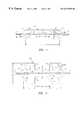
- FIG. 1is a side view of a tube-encased fiber grating, in accordance with the present invention.
- FIG. 2is a side view of a tube-encased fiber grating having an alternative geometry for the tube, in accordance with the present invention.
- FIG. 3is a side view of a tube-encased fiber grating having an alternative geometry for the tube, in accordance with the present invention.
- FIG. 4is a side view of a tube-encased fiber grating having an alternative geometry for the tube, in accordance with the present invention.
- FIG. 5is a side view of a glassencased fiber grating having more than one tube around the grating, in accordance with the present invention.
- FIG. 6is a side view of a tube-encased fiber grating where the tube is fused on opposite axial ends of the grating area, in accordance with the present invention.
- FIG. 7is a side view of an alternative tube-encased fiber grating where the tube is fused on opposite axial ends of the grating area, in accordance with the present invention.
- FIG. 8is a side view of a more than one grating on a fiber encased in a tube, in accordance with the present invention.
- FIG. 9is a side view of two fiber grating on two separate optical fibers encased in a common tube, in accordance with the present invention.
- FIG. 10is an end view of the embodiment of FIG. 9, in accordance with the present invention.
- FIG. 11is an end view of two fiber gratings on two separate optical fibers encased in a common tube and separated by distance, in accordance with the present invention.
- FIG. 12is a side view of a tube-encased fiber grating where the tube is fused on the fiber only over the length of the grating, in accordance with the present invention.
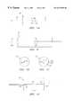
- FIG. 13is a diagram showing a process for encasing a fiber in a glass tube, in accordance with the present invention.
- FIG. 14is a side view of a tunable fiber DFB laser encased in a tube, in accordance with the present invention.
- FIG. 15is a graph of an optical transmission profile of a grating in a standard optical fiber showing cladding mode coupling, in accordance with the present invention.
- FIG. 16is a graph of an optical transmission profile of a tubeencased fiber grating showing reduced cladding mode coupling, in accordance with the present invention.
- a tube-encased fiber Bragg gratingcomprises a known optical waveguide 10 , e.g., a standard telecommunication single mode optical fiber, having a Bragg grating 12 impressed (or embedded or imprinted) in the fiber 10 .
- the fiber 10has an outer diameter of about 125 microns and comprises silica glass (SiO 2 ) having the appropriate dopants, as is known, to albw light 14 to propagate along the fiber 10 .
- the grating 12is similar to that described in U.S. Pat. Nos. 4,725,110, and 4,807,950, entitled “Method for Impressing Gratings Within Fiber Optics”, to Glenn et al; and U.S. Pat. No.
- the fiber 10may be made of any glass, e.g., silica, phosphate glass, or other glasses, or made of glass and plastic, or solely plastic. For high temperature applications, optical fiber made of a glass material is desirable. Also, the fiber 10 may have an outer diameter of 80 microns or other diameters. Further, instead of an optical fiber, any optical waveguide may be used, such as, a multi-mode, birefringent, polarization maintaining, polarizing, multi-core, or multicladding optical waveguide, or a flat or planar waveguide (where the waveguide is rectangular shaped), or other waveguides. As used herein the term “fiber” includes the above described waveguides.
- the light 14is incident on the grating 12 which reflects a portion thereof as indicated by a line 16 having a predetermined wavelength band of light centered at a reflection wavelength ⁇ b, and passes the remaining wavelengths of the incident light 14 (within a predetermined wavelength range), as indicated by a line 18 .
- the fiber 10 with the grating 12 thereinis encased within and fused to at least a portion of a cylindrical glass capillary tube 20 having an outer diameter dl of about 3 mm and a length L 1 of about 10 mm.
- the grating 12has a length Lg of about 5 mm.
- the length L 1 of the tube 20may be substantially the same length as the length Lg of the grating 12 , such as by the use of a longer grating, or a shorter tube. Other dimensions and lengths for the tube 20 and the grating 12 may be used.
- the fiber 10 and grating 12need not be fused in the center of the tube 20 but may be fused anywhere in the tube 20 .
- the tube 20need not be fused to the fiber 10 over the entire length L 1 of the tube 20 .
- the tube 20is made of a glass material, such as natural or synthetic quartz, fused silica, silica (SiO 2 ), Pyrex® by Corning (boro silicate), or Vycor® by Coming (about 95% silica and 5% other constituents such as Boron Oxide), or other glasses.
- a glass materialsuch as natural or synthetic quartz, fused silica, silica (SiO 2 ), Pyrex® by Corning (boro silicate), or Vycor® by Coming (about 95% silica and 5% other constituents such as Boron Oxide), or other glasses.
- the tubeshould be made of a material such that the tube 20 (or the inner diameter surface of a bore hole in the tube 20 ) can be fused to (i.e., create a molecular bond with, or melt together with) the outer surface (or cladding) of lie optical fiber 10 such that the interface surface between the inner diameter of the tube 20 and the outer diameter of the fiber 10 become substantially eliminated (i.e., the inner diameter of the tube 20 cannot be distinguished from the cladding of the fiber 10 ).
- the coefficient of thermal expansion (CTE) of the material of the tube 20should substantially match the CTE of the material of the fiber 10 , e.g.,fused silica tube and optical fiber.
- the lower the melting temperature of the glass materialthe higher the CTE.
- a silica fiberhaving a high melting temperature and low CTE
- a tube made of another glass materialsuch as Pyrex® or Vycor® (having a lower melting temperature and higher CTE) results in a thermal expansion mismatch between the tube 20 and the fiber 10 over temperature.
- the CTE of the fiber 10match the CTE of the tube 20 (discussed more hereinafter).
- the tube 20being made of a glass material
- other materialsmay be used provided the tube 20 can be fused to the fiber 10 .
- a tube made of a plastic materialmay be used for an optical fiber made of plastic.
- the axial ends of the tube 20 where the fiber 10 exits the tube 20may have an inner region 22 which is inwardly tapered (or flared) away from the fiber 10 to provide strain relief for the fiber 10 or for other reasons.
- an area 28 between the tube 20 and the fiber 10may be filled with a strain relief filler material, e.g., polyimide, silicone, or other materials.
- the tube 20may have tapered (or beveled or angled) outer comers or edges 24 to provide a seat for the tube 20 to mate with another part (not shown) and/or to adjust the force angles on the tube 20 , or for other reasons.
- the angle of the beveled corners 24are set to achieve the desired function.
- the tube 20may have cross-sectional shapes other than circular, such as square, rectangular, elliptical, clam-shell ,or other shapes, and may have side-view sectional shapes other than rectangular, such as circular, square, elliptical, clamshell, or other shapes.
- one or both of the axial ends of the tube 20 where the fiber 10 exits the tube 20may have an outer tapered (or fluted, conical, or nipple) section, shown as dashed lines 27 , which has an outer geometry that decreases down to the fiber 10 (discussed more hereinafter with FIG. 12 ).
- an outer tapered (or fluted, conical, or nipple) sectionshown as dashed lines 27 , which has an outer geometry that decreases down to the fiber 10 (discussed more hereinafter with FIG. 12 ).
- the fluted sections 27provides enhanced pull strength at and near the interface where the fiber 10 exits the tube 20 , e.g., 6 lbf or more, when the fiber 10 is pulled along its longitudinal axis.
- the fiber 10may have an external protective buffer layer 21 to protect the outer surface of the fiber 10 from damage.
- the buffer 21may be made of polyimide, silicone, Teflon® (polytetraflouroethylene), carbon, gold, and/or nickel, and have a thickness of about 25 microns. Other thicknesses and buffer materials for the buffer layer 21 may be used. If the inner tapered region 22 is used and is large enough, the buffer layer 21 may be inserted into the region 22 to provide a transition from the bare fiber to a buffered fiber. Alternatively, if the axial end of the tube 20 has the external taper 27 , the buffer 21 would begin where the fiber exits the tapered 27 portion of the tube 20 .
- the exposed bare portion of the fiber 10may be recoated with an additional buffer layer (not shown) which covers any bare fiber outside of the tube 20 and may also overlap with the buffer 21 and/or some of the tapered region 27 or other geometrically shaped axial end of the tube 20 .
- the tube 20may be heated, collapsed and fused around the grating 12 (or grating area) as discussed hereinafter.
- the Bragg grating 12may be impressed in the fiber 10 before or after the capillary tube 20 is encased around the fiber 10 and grating 12 .
- the fiber 10 and/or the grating 12may be fused to the tube 20 having an initial pre-strain on the fiber 10 and/or grating 12 (compression or tension) or no pre-strain.
- the fiber grating 12may be encased in the tube 20 in tension by putting the grating in tension during the tube heating and fusing process.
- the fiber grating 12may be encased in the tube 20 resulting in neither tension nor compression on the grating 12 .
- the grating 12may be written through the tube 20 into the fiber 10 as is described in copending U.S. patent application, Ser. No. 09/205,845, now U.S. Pat. No. 6,298,184, (Cidra Docket No. CC-0130), entitled “Method and Apparatus For Forming A Tube-Encased Bragg Grating”, filed Dec. 4, 1998, and incorporated herein by reference.
- the melting temperature of the capillary tube 20should be low enough to allow the glass tube 20 to become soft and fuse to the optical fiber 10 without significantly “bleaching out” (or annealing or weakening) the grating 12 reflectivity below the desired level, which may occur when a grating is exposed to high temperatures.
- Capillary tubing made of Pyrex® or equivalent glasshas a softening temperature lower than that of a quartz fiber and thus is suitable for this purpose.
- the grating 12is put in compression by the tube 20 .
- the fiber grating 12may be encased in the tube 20 in tension by putting the grating in tension during the tube heating and fusing process.
- the fiber grating 12may be encased in the tube 20 resulting in neither tension nor compression on the grating 12 .
- the capillary tube 20may have a varying geometry, depending on the application.
- the tube 20may have a “dogbone” shape having a narrow central section 30 and larger outer sections 32 .
- the narrow section 30has an outer diameter d 2 of about 2 mm, and a length L 2 of about 9.25 mm.
- the large sections 32have an outer diameter d 3 of about 4 mm and a length L 3 of about 6.35 mm.
- Other lengths L 2 ,L 3 of the sections 30 , 32may beused.
- the length L 3may be much more than 6.36 mm (e.g., greater than 25.4 mm long) or may be much less than 6.36 mm long.
- the dogbone shapemay be used to provide increased force to grating wavelength shift sensitivity when used in a compression-based force or pressure sensor application or for gripping the tube 20 in a tension configuration, such as is described in copending U.S. patent application, Ser. No. 09/455,867 (CiDRA Docket No. CC-0036B), entitled “Fiber Grating Pressure Sensor”, or a compression based tunable grating and laser application such as is described in Copending U.S. Pat. No. 6,229,827 (CiDRA Docket No. CC-0129B), entitled “Compression Tuned Fiber Grating and Laser”, filed contemporaneously herewith, or may be used for other applications.
- the dimensions for the dogboneare easily scalable to provide the desired amount of sensitivity.
- An inner transition region 33 of the large sections 32may be a sharp edge or may be curved as indicated by dashed lines 34 .
- a curved geometry 34has less stress risers than a sharp edge or comer and thus reduces the likelihood of breakage.
- the sections 32 of the tube 20may have the inner tapered regions 22 or the outer fluted sections 27 at the ends of the tube 20 , as discussed hereinbefore. Further, the sections 32 may have the tapered (or beveled) outer corners 24 as discussed hereinbefore.
- the dogbone geometrybe symmetric, e.g., the lengths L 3 of the two sections 32 may be different if desired.
- the dogbonemay be a single-sided dogbone, where instead of the having the two larger sections 32 , there may be only large section 32 on one side of the narrow section 30 and the other side may have a straight edge 37 which may have beveled comers 24 as discussed hereinbefore. In that case, the dogbone has the shape of a “T” on its side.
- Such a single-sided dogboneshall also be referred to herein as a “dogbone” shape.
- other geometriesthat provide enhanced strain sensitivity or adjust force angles on the tube 20 or provide other desirable characteristics may be used.
- an alternative geometry for the capillary tube 20may have other axial extending geometries.
- the left side of the tube 20may have an axial extended section 36 which may have the fluted section 27 at the end.
- the right side of the tube 20may have an axial extended section 51 (which may have the fluted section 27 at the end) that is longer than the other axial end 36 .
- the fiber 10 in one or both of the axial extended sections 36 , 51may have gratings 52 , 50 , respectively.
- L 6is about 26.7 mm
- L 7is about 11.66 mm
- L 8is about 12.7 mm
- L 9is about 2.29 mm
- d 7is about 0.813 mm
- d 2 ,d 3 and the other dimensions of the dogboneare as discussed hereinbefore.
- the long axial end 51may be made by the methods discussed herein for making the dogbone or other shapes for the tube 20 , or may be made by fusing the section 51 to the section 32 (before or after the fiber 10 is encased in the tube 20 ) at a point 53 or may be made.
- the tube 20 shown in FIG. 3 with the section 51may be formed by using two tubes, an inner tube with the length L 6 slid through a hole 58 in the dogbone sections 30 , 32 and fused to the sections 30 , 32 similar to that discussed hereinafter with FIG. 5 .
- the long axial end 51may be fused to the fiber 10 near where the grating 50 is located and not fused onto the fiber 10 at a region 90 near the end of the section 51 .
- the region 90may be filled with an epoxy or other filler discussed hereinbefore.
- the inner diameter d 6 of the tube 20 in the section 90is about 0.01 to 10 microns larger than the diameter of the optical fiber 10 , e.g., 125.01 to 135 microns. Other diameters and dimensions may be used if desired.
- the fiber 10may have the external protective buffer layer 21 to protect the outer surface of the fiber 10 from damage, as discussed hereinbefore.
- more than one concentric tubemay be fused together to form the tube 20 of the tube-encased grating of the present invention.
- a small inner capillary tube 180 having an outer diameter d 4 of about 0.5 mm (0.0197 in.)may be located within a larger outer capillary tube 182 , having the diameter d 1 discussed hereinbefore, and the two tubes 180 , 182 are fused together.
- One or both ends of the small tube 180may be shrunk down around the fiber 10 to form the fluted sections 27 .
- Other values for the diameters d 1 , d 4 , of the inner and outer tubes 180 , 182may be used if desired.
- more than two concentric capillary tubesmay be used.
- the material of the tubesmay be the same to minimize thermal expansion mismatch over temperature.
- the shape of the outer tube 182may have a dogbone shape as indicated by dashed lines 184 , or other shapes as discussed hereinbefore.
- the dogbone shapemay be created by fusing two separate tubes 188 , 190 onto the inner tube 180 on opposite axial sides of the grating 12 , as indicated by dashed lines 186 .
- regions 200 of the tube 20are fused to the fiber 10 and a central section 202 of the tube around the grating 12 is not fused to the fiber 10 .
- the region 202 around the grating 12may contain ambient air or be evacuated (or be at another pressure) or may be partially or totally filled with an adhesive, e.g., epoxy, or other filling material, e.g., a polymer or silicone, or another material.
- the inner diameter d 6 of the tube 20is about 0.01 to 10 microns larger than the diameter of the optical fiber 10 , e.g., 125.01 to 135 microns. Other diameters may be used; however, to help avoid fiber buckling when the tube 20 is axially compressed, the diameter d 6 should be as close as possible to the fiber 10 outer diameter. Also, the distance L 10 need not be symmetric around both sides of the grating 12 . Referring to FIG. 7, alternatively, the same result can be achieved by fusing two separate tubes 210 , 212 on opposite sides of the grating 12 and then fusing an outer tube 214 across the tubes 210 , 212 .
- the tubes 210 , 212may extend beyond the ends of the outer tube 214 as indicated by the dashed lines 216 .
- the tube 20may be a single piece with a shape indicative of the tubes 210 , 212 , 214 .
- two or more gratings 150 , 152may be embedded in the fiber 10 that is encased in the tube 20 .
- the gratings 150 , 152may have the same reflection wavelengths and/or profiles or different wavelengths and/or profiles.
- the multiple gratings 150 , 152may be used individually in a known Fabry Perot arrangement.
- one or more fiber laserssuch as that described in U.S. Pat. No. 5,513,913, entitled “Active Multipoint Fiber Laser Sensor”, U.S. Pat. No. 5,564,832, entitled “Birefringent Active Fiber Laser Sensor”, or U.S. Pat. No.
- “Compression Tuned Fiber Laser”may be embedded within the fiber 10 in the tube 20 , which are incorporated herein by reference to the extent necessary to understand the present invention.
- the gratings 150 , 152form an optical cavity and the fiber 10 at least between the gratings 150 , 152 (and may also include the gratings 150 , 152 and/or the fiber outside the gratings, if desired) would be doped with a rare earth dopant, e.g., erbium and/or ytterbium, etc.
- tunable fiber laseranother type of tunable fiber laser that may be used is a tunable distributed feedback (DFB) fiber laser, such as that described in V. C. Lauridsen, et al, “Design of DFB Fibre Lasers”, Electronic Letters, Oct. 15, 1998, Vol. 34, No. 21, pp 2028-2030; P. Varming, et al, “Erbium Doped Fiber DGB Laser With Permanent ⁇ /2 Phase-Shift Induced by UV Post-Processing”, IOOC'95, Tech. Digest, Vol. 5, PD1-3, 1995; U.S. Pat. No. 5,771,251, “Optical Fibre Distributed Feedback Laser”, to Kringlebotn et al; or U.S. Pat. No.
- DFBdistributed feedback
- the grating 12is written in a rare-earth doped fiber and configured to have a phase shift of ⁇ /2 (where ⁇ is the lasing wavelength) at a predetermined location 180 near the center of the grating 12 which provides a well defined resonance condition that may be continuously tuned in single longitudinal mode operation without mode hopping, as is known.
- the two gratings 150 , 152may be placed close enough to form a cavity having a length of (N+1 ⁇ 2) ⁇ where N is an integer (including 0) and the gratings 150 , 154 are in rare-earth doped fiber.
- two or more fibers 10 , 250may be encased within the tube 20 .
- the bore hole in the tube 20 prior to heating and fusing the tube 20would be large enough to house both fibers and may be other than circular, e.g., square, triangle, etc.
- the bore hole for the tube 20need not be centered along the center line of the tube 20 .
- the fibers 10 , 250may be spaced apart in the tube 20 by a predetermined distance.
- the distancemay be any desired distance between the fibers 10 , 250 and have any orientation within the outer diameter of the tube 20 .
- part or all of an optical fiber andlor gratingmay be fused within, partially within or on the outer surface of the tube 20 , as indicated by the fibers 500 , 502 , 504 , respectively.
- the tube 20may be fused onto the fiber 10 only where the grating 12 is located.
- the inner tapered or flared regions 22 discussed hereinbeforemay exist and the areas 28 between the tube 20 and the fiber 10 may be filled with a filler material, as discussed hereinbefore.
- one technique and configuration for fusing the tube 20 around the fiber 10is as follows.
- the tube 20is slid over the fiber 10 to a location where the grating 12 exists or will exist.
- the top end of the tube 20is connected to the bottom end of a rigid holding, alignment, and vacuum tube 350 having a gear 351 attached thereto.
- the top end of the tube 350is connected to one endof a vacuum connector 352 which has a rotating vacuum seal 354 .
- the other end of the vacuum connector 352is connected to one end of a flexible vacuum tube 356 .
- the other end of the vacuum tube 356is connected to a vacuum pump 358 .
- the vacuum pump 358creates a vacuum within the tube 20 to create a collapsing force on the tube 20 sufficient to cause the tube 20 to collapse onto the fiber 10 when heated.
- the tube 20is held in place and sealed by an epoxy seal 360 to hold a vacuum in the rigid tube 350 .
- the bottom end 361 of the tube 20may be plugged or sealed by the outer buffer layer 21 (FIG. 4) of the fiber 10 , by epoxy or by other means to allow the vacuum to exist in the tube 20 . Other seals may be used.
- the connector 352is attached to a rotating motor 362 that is connected to a gear 366 that meshes with the gear 351 attached to the vacuum tube 350 .
- the motor 362rotates, it rotates the gear 366 , that rotates the other gear 351 , that causes the tube 350 , the tube 20 , and the fiber 10 to rotate about the longitudinal axis of the fiber 10 and the tube 20 , as indicated by the arrow 367 .
- the tube 20 and fiber 10are rotated to provide even circumferential heating of the tube 20 and the fiber 10 .
- the connector 352is also attached to a moving member 368 of a vertical translation stage 370 that has a screw gear 372 that is attached to a second motor 371 .
- the gear 372meshes with and vertically moves the member 368 , the connector 352 , and the motor 362 up or down along the translation stage 370 as indcated by arrows 374 .
- Other configurations and hardwaremay be used to rotate and translate the tube 20 .
- a stationary heat source 380such as CO 2 laser, e.g., LC-50 laser by DeMaria Electro Optic Systems, provides a predetermined amount of heat to a locaized area 382 of the tube 20 (which performs a laser weld) and is configured to allow the tube to move vertically through the heating area 382 .
- the laser 380provides a laser beam 384 , having a 3 mm diameter with about 30 to 40 Watts of power at the tube 20 at a wavelength of about 10.6 microns. Other powers, beam sizes and shapes may be used provided that the appropriate amount of heat is applied to the tube 20 .
- the tube 20may be illuminated on multiple locations around the circumference of the tube 20 or completely around the tube 20 .
- flat or cylindrical mirrorsmay be used to slit and/or reflect the beam 384 simultaneously to desired regions around the circumference of the tube 20 .
- heating devices and/or heating techniquesmay be used if desired, such as a torch (e.g., a propane/oxygen or oxygen/hydrogen torch), a tungsten (or molybdenum) filament heater, another type of laser, tiny oven (e.g., filament wire within an insulated housing), or any other heating technique that provides sufficient heat to collapse the tube 20 onto the fiber 10 .
- a torche.g., a propane/oxygen or oxygen/hydrogen torch
- tungsten (or molybdenum) filament heatere.g., tungsten (or molybdenum) filament heater
- tiny ovene.g., filament wire within an insulated housing
- any other heating techniquethat provides sufficient heat to collapse the tube 20 onto the fiber 10 .
- the heat source 380applies heat evenly around the circumference of the fiber 10 and the tube 20 , the tube 20 and the fiber 10 may not need to be rotated about the longitudinal axis of the fiber 10 during heating.
- a vacuuminstead of a vacuum, other techniques may be used to create a collapsing force on the tube 20 .
- creating an external pressure on the tube 20while keeping the internal tube pressure below the external pressure.
- the external pressuremay be exerted by mechanical or hydraulic or other means.
- the inner diameter d 6 (FIGS. 4 , 6 ) of the tube 20is very close to the outer diameter of the fiber, e.g., about 1 micron larger (about 126 micron inner diameter), the tube 20 may collapse onto the fiber 10 under its own surface tension without the need for a vacuum or other collapsing force.
- an intermediate or filler material having a similar composition to that of the fiber 10 and the tube 20such as a fine glass powder or solder (e.g., silica powder), may be used between the fiber 10 and the tube 20 and which becomes fused to both the tube 20 and the fiber 10 to facilitate the fusing process.
- a fine glass powder or soldere.g., silica powder
- the tube 20may not collapse as much (or at all) as it fuses to the fiber 10 .
- the tube 20is heated and fused from the bottom-up (toward the vacuum source) using the heater 380 .
- the tube 20is heated at a predetermined temperature (e.g., about 1800 deg. C. for a quartz or fused silica tube) until the tube 20 is soft enough to collapse under the collapsing forces and fuse to the tube 20 , then the tube 20 is moved to the next section to be heated and fused.
- a predetermined temperaturee.g., about 1800 deg. C. for a quartz or fused silica tube
- the tube 20is moved to the next section to be heated and fused.
- the translation stagemoves the tube 20 vertically at a rate of about 0.06 mm/sec and the tube 20 is rotated at a rate of about 100 rpm. Other translation and rotation rates may be used if desired.
- the longitudinal axis of the tube 20 and fiber 10are oriented vertically during heating to minimize gravitational effects and optimize axial symmetry; however, other orientations may be used if desired. Also, instead of moving the tube 20 and fiber 10 , the heat source 56 may be moved vertically or both the heat source 380 and the fiber/tube may be moved.
- the fiber 10may be fused to the tube 20 , such as using a high temperature glass solder, e.g., a silica solder (powder or solid), such that the fiber 10 , the tube 20 and the solder all become fused to each other, or using laser welding/fusing or other fusing techniques.
- a high temperature glass soldere.g., a silica solder (powder or solid)
- the fibermay be fused within the tube or partially within or on the outer surface of the tube (discussed hereinafter with FIG. 11 ).
- the tube 20may be split longitudinally into two or more pieces and assembled together at the desired location of the grating 12 for fusing to the fiber 10 .
- the fluted sections 27may be formed in various ways, such as by heating the tube 20 and pulling the tube 20 and/or the fiber 10 .
- the fluted ends 27 of the tube 20may be formed using other glass formation techniques such as grinding, polishing or etching the axial ends of the capillary tube 20 .
- chemical etchinge.g., with hydrofluoric acid or other chemical etches
- laser etchingor laser enhanced chemical etching are some techniques which reduce the outer diameter without applying direct contact force as is required by grinding and polishing.
- Other techniquesmay be used to obtain the fluted ends 27 .
- the sections 27may be created before, during, or after the heating and fuising of the tube 20 to the fiber 10 .
- the inner tapered region 22may be created by numerous techniques. For example, not fusing the tube 20 to the fiber 10 in the regions 22 or to create a region 22 that is larger than the inner diameter of the tube 20 , the tube 20 may be heated in the desired region to be expanded and internal pressure applied to the tube 20 .
- the dogbone geometry discussed hereinbeforemay be formed by etching, grinding, or polishing the central section of the capillary tube 20 to obtain the narrow diameter d 2 and/or the beveled corners 24 , such as that described hereinbefore regarding the fluted sections 27 . Other techniques may be used to obtain the narrow diameter region 30 and corners 24 . After the dogbone (or other geometry) is formed in the tube 20 , the surface of the tube 20 may be fire polished to remove surface impurities, to enhance strength, or for other reasons.
- the fiber 10may be single-ended, i.e., only one end of the fiber 10 exits the tube 20 . In that case, one end of the fiber 10 would be at the exit point of the fiber 10 from the tube 20 or prior to the exit point.
- the term “tube” as used hereinmay also mean a block of material having the properties described herein.
- the present inventionalso reduces coupling between the core and cladding modes typically caused by a fiber grating, due to the increased end cross-sectional area between the core and cladding of the fiber 10 .
- a grating 12 written in the core of the optical fiber 10exhibits less optical transmission loss and a exhibits a cleaner optical profile than a conventional fiber grating because the large cladding region dissipates coupled cladding modes, thereby reducing the coupling of the core to the cladding modes.
- the greater the difference in cross-sectional area between the core and the claddingthe smaller the mode field overlap and the lower the coupling to the cladding modes.
- FIG. 15shows an optical transmission profile for a standard grating in an optical fiber having a 9 micron core diameter and 125 micron outer diameter. Such a grating exhibits coupling to the cladding modes as indicated by the spikes 100 .
- FIG. 15shows an optical transmission profile for a standard grating in an optical fiber having a 9 micron core diameter and 125 micron outer diameter. Such a grating exhibits coupling to the cladding modes as indicated by the spikes 100 .
- FIG. 16shows an optical transmission profile for a tube-encased grating described herein having a 9 micron core diameter and a 3 mm outer diameter tube 20 which exhibits greatly reduced coupling to the cladding modes as indicated by the lack of spikes on the profile.
- Other diameters of the fiber core and the tube 20may be used if desired such that the optical coupling tothe cladding modes is reduced to the desired levels.
Landscapes
- Physics & Mathematics (AREA)
- General Physics & Mathematics (AREA)
- Optics & Photonics (AREA)
- Light Guides In General And Applications Therefor (AREA)
- Lasers (AREA)
- Insulators (AREA)
- Semiconductor Lasers (AREA)
- Mechanical Coupling Of Light Guides (AREA)
- Preliminary Treatment Of Fibers (AREA)
- Yarns And Mechanical Finishing Of Yarns Or Ropes (AREA)
- Tires In General (AREA)
Abstract
Description
Claims (41)
Priority Applications (17)
| Application Number | Priority Date | Filing Date | Title |
|---|---|---|---|
| BR9915953-8ABR9915953A (en) | 1998-12-04 | 1999-12-06 | Fiber optic device enclosed in a tube, method for enclosing an optical reflective element in a tube, and optical reflective element enclosed in a tube |
| AU41644/00AAU757885B2 (en) | 1998-12-04 | 1999-12-06 | Tube-encased fiber grating |
| CA002353413ACA2353413C (en) | 1998-12-04 | 1999-12-06 | Tube-encased fiber grating |
| AT99972433TATE265055T1 (en) | 1998-12-04 | 1999-12-06 | TUBE CONVEYING FIBER GRID |
| PCT/US1999/028865WO2000039617A2 (en) | 1998-12-04 | 1999-12-06 | Tube-encased fiber grating |
| KR1020017006991AKR20010080687A (en) | 1998-12-04 | 1999-12-06 | Tube-encased fiber grating |
| CN99816041ACN1334929A (en) | 1998-12-04 | 1999-12-06 | Tube-encased fibre grating |
| DE69916659TDE69916659D1 (en) | 1998-12-04 | 1999-12-06 | PIPE CONVEYING FIBER GRID |
| EP99972433AEP1145059B1 (en) | 1998-12-04 | 1999-12-06 | Tube-encased fiber grating |
| US09/455,865US6519388B1 (en) | 1998-12-04 | 1999-12-06 | Tube-encased fiber grating |
| JP2000591459AJP2002533779A (en) | 1998-12-04 | 1999-12-06 | Fiber grating housed in a tube |
| NO20012681ANO20012681L (en) | 1998-12-04 | 2001-05-31 | Tube enclosed fiberglass |
| US10/098,890US6834142B2 (en) | 1998-12-04 | 2002-03-15 | Optical grating-based filter |
| US10/098,891US6996316B2 (en) | 1999-09-20 | 2002-03-18 | Large diameter D-shaped optical waveguide and coupler |
| US10/224,157US6763043B2 (en) | 1998-12-04 | 2002-08-20 | Tunable grating-based dispersion compensator |
| US10/226,944US6792009B2 (en) | 1998-12-04 | 2002-08-22 | Tunable grating-based channel filter parking device |
| US10/456,790US20030215185A1 (en) | 1999-12-06 | 2003-06-06 | Large diameter optical waveguide having long period grating therein |
Applications Claiming Priority (3)
| Application Number | Priority Date | Filing Date | Title |
|---|---|---|---|
| US20594398A | 1998-12-04 | 1998-12-04 | |
| US39949599A | 1999-09-20 | 1999-09-20 | |
| US09/455,865US6519388B1 (en) | 1998-12-04 | 1999-12-06 | Tube-encased fiber grating |
Related Parent Applications (1)
| Application Number | Title | Priority Date | Filing Date |
|---|---|---|---|
| US39949599AContinuation-In-Part | 1998-12-04 | 1999-09-20 |
Related Child Applications (4)
| Application Number | Title | Priority Date | Filing Date |
|---|---|---|---|
| US09/455,868Continuation-In-PartUS6982996B1 (en) | 1998-12-04 | 1999-12-06 | Large diameter optical waveguide, grating, and laser |
| US10/224,157Continuation-In-PartUS6763043B2 (en) | 1998-12-04 | 2002-08-20 | Tunable grating-based dispersion compensator |
| US10/226,944Continuation-In-PartUS6792009B2 (en) | 1998-12-04 | 2002-08-22 | Tunable grating-based channel filter parking device |
| US10/456,790ContinuationUS20030215185A1 (en) | 1999-12-06 | 2003-06-06 | Large diameter optical waveguide having long period grating therein |
Publications (1)
| Publication Number | Publication Date |
|---|---|
| US6519388B1true US6519388B1 (en) | 2003-02-11 |
Family
ID=27394874
Family Applications (1)
| Application Number | Title | Priority Date | Filing Date |
|---|---|---|---|
| US09/455,865Expired - LifetimeUS6519388B1 (en) | 1998-12-04 | 1999-12-06 | Tube-encased fiber grating |
Country Status (12)
| Country | Link |
|---|---|
| US (1) | US6519388B1 (en) |
| EP (1) | EP1145059B1 (en) |
| JP (1) | JP2002533779A (en) |
| KR (1) | KR20010080687A (en) |
| CN (1) | CN1334929A (en) |
| AT (1) | ATE265055T1 (en) |
| AU (1) | AU757885B2 (en) |
| BR (1) | BR9915953A (en) |
| CA (1) | CA2353413C (en) |
| DE (1) | DE69916659D1 (en) |
| NO (1) | NO20012681L (en) |
| WO (1) | WO2000039617A2 (en) |
Cited By (39)
| Publication number | Priority date | Publication date | Assignee | Title |
|---|---|---|---|---|
| US20020069676A1 (en)* | 2000-12-12 | 2002-06-13 | Kopp Victor Il?Apos;Ich | Apparatus and method of manufacturing chiral fiber bragg gratings |
| US20030121289A1 (en)* | 2002-01-02 | 2003-07-03 | Benda John A. | Long period fiber Bragg gratings written with alternate side IR laser illumination |
| US6626043B1 (en)* | 2000-01-31 | 2003-09-30 | Weatherford/Lamb, Inc. | Fluid diffusion resistant glass-encased fiber optic sensor |
| US20040129083A1 (en)* | 1998-12-04 | 2004-07-08 | Weatherford/Lamb, Inc. | Optical differential pressure sensor |
| US20040165834A1 (en)* | 2003-01-10 | 2004-08-26 | Bryant Rebecca S. | Low-loss large-diameter pigtail |
| US20040165841A1 (en)* | 2003-01-10 | 2004-08-26 | Fernald Mark R. | Large diameter optical waveguide splice |
| US20040179766A1 (en)* | 2001-12-14 | 2004-09-16 | Williams Forrest L. | Fiber optic mechanical/thermal tuner and isolator |
| US20040182166A1 (en)* | 2003-03-21 | 2004-09-23 | Jones Richard Todd | Optical differential pressure transducer utilizing a bellows and flexure system |
| US20040234200A1 (en)* | 2003-05-21 | 2004-11-25 | Jennings Robert M. | Apparatus and method for non-linear thermal compensation of optical waveguide gratings |
| US20050088660A1 (en)* | 2003-10-24 | 2005-04-28 | Erlend Ronnekleiv | Downhole optical sensor system with reference |
| US20050094129A1 (en)* | 2003-10-29 | 2005-05-05 | Macdougall Trevor | Combined Bragg grating wavelength interrogator and brillouin backscattering measuring instrument |
| US6982996B1 (en)* | 1999-12-06 | 2006-01-03 | Weatherford/Lamb, Inc. | Large diameter optical waveguide, grating, and laser |
| US20060034559A1 (en)* | 2004-08-10 | 2006-02-16 | Petroleo Brasileiro S.A. - Petrobras, Rio De Janerio, Rj | Optical transducer and method for the simultaneous measurement of pressure and temperature in oil and gas wells |
| US20060093275A1 (en)* | 2004-10-29 | 2006-05-04 | Michael Lagace | Optical connector assembly |
| US20070065071A1 (en)* | 2005-06-30 | 2007-03-22 | Infoscitex | Humidity sensor and method for monitoring moisture in concrete |
| US20070116402A1 (en)* | 2005-06-30 | 2007-05-24 | Infoscitex Corporation | Humidity sensor and method for monitoring moisture in concrete |
| US20070193362A1 (en)* | 2006-02-06 | 2007-08-23 | Ferguson Stephen K | Fiber optic strain gage |
| US7266180B1 (en)* | 2003-08-06 | 2007-09-04 | General Electric Company | Method of manufacturing a collimator mandrel having variable attenuation characteristics for a CT system |
| WO2008101657A1 (en)* | 2007-02-19 | 2008-08-28 | Hottinger Baldwin Messtechnik Gmbh | Optical strain gauge |
| US20080247718A1 (en)* | 2003-04-24 | 2008-10-09 | Dowd Edward M | Fiber optic cable systems and methods to prevent hydrogen ingress |
| US20090059211A1 (en)* | 2007-07-18 | 2009-03-05 | Sungkyunkwan University Foundation For Corporate Collaboration | Optical biosensor using spr phenomenon |
| US20090097222A1 (en)* | 2004-06-25 | 2009-04-16 | Wilfried Babutzka | Electrical Subassembly Comprising a Protective Sheathing |
| US20090126501A1 (en)* | 2007-11-15 | 2009-05-21 | Ferguson Stephen K | Fiber optic strain gage and carrier |
| WO2010150118A1 (en)* | 2009-06-08 | 2010-12-29 | Ramot At Tel Aviv University Ltd. | Single-waveguide bio-sensor based on propagating modes in a grating waveguide |
| US7891818B2 (en) | 2006-12-12 | 2011-02-22 | Evans & Sutherland Computer Corporation | System and method for aligning RGB light in a single modulator projector |
| US20110229071A1 (en)* | 2009-04-22 | 2011-09-22 | Lxdata Inc. | Pressure sensor arrangement using an optical fiber and methodologies for performing an analysis of a subterranean formation |
| US8077378B1 (en) | 2008-11-12 | 2011-12-13 | Evans & Sutherland Computer Corporation | Calibration system and method for light modulation device |
| US20120132008A1 (en)* | 2010-10-19 | 2012-05-31 | Way Donald R | Fiber optic load measurement device |
| US8358317B2 (en) | 2008-05-23 | 2013-01-22 | Evans & Sutherland Computer Corporation | System and method for displaying a planar image on a curved surface |
| US20140085626A1 (en)* | 2012-09-24 | 2014-03-27 | T&S Communications Co., Ltd. | Optical fiber grating tracker and method for detecting optical fiber line fault |
| US8702248B1 (en) | 2008-06-11 | 2014-04-22 | Evans & Sutherland Computer Corporation | Projection method for reducing interpixel gaps on a viewing surface |
| US20140327919A1 (en)* | 2013-05-06 | 2014-11-06 | Halliburton Energy Services. Inc. | Remote Seal for Pressure Sensor |
| US9641826B1 (en) | 2011-10-06 | 2017-05-02 | Evans & Sutherland Computer Corporation | System and method for displaying distant 3-D stereo on a dome surface |
| CN106898939A (en)* | 2017-04-18 | 2017-06-27 | 南京理工大学 | Low reflective grid and cladding light power stripper combination device in optical fiber laser |
| US9857250B2 (en)* | 2013-12-27 | 2018-01-02 | Cmiws Co., Ltd. | Strain sensor and method for installing strain sensor |
| CN107681420A (en)* | 2016-08-01 | 2018-02-09 | 南京理工大学 | Double clad fiber cladding photospallation heat abstractor based on chemical corrosion method |
| DE102017120062A1 (en)* | 2017-08-31 | 2019-02-28 | fos4X GmbH | Mounting method, fastening device, use of a fastening device and temperature sensor |
| CN112230327A (en)* | 2020-10-28 | 2021-01-15 | 胡仲春 | Full-glass packaging device and packaging method for fiber bragg grating |
| CN113790821A (en)* | 2021-08-24 | 2021-12-14 | 南京邮电大学 | A kind of high temperature fiber Bragg grating temperature sensor and manufacturing method |
Families Citing this family (43)
| Publication number | Priority date | Publication date | Assignee | Title |
|---|---|---|---|---|
| US6763043B2 (en) | 1998-12-04 | 2004-07-13 | Cidra Corporation | Tunable grating-based dispersion compensator |
| US6792009B2 (en) | 1998-12-04 | 2004-09-14 | Cidra Corporation | Tunable grating-based channel filter parking device |
| US6834142B2 (en) | 1998-12-04 | 2004-12-21 | Cidra Corporation | Optical grating-based filter |
| US7386204B1 (en) | 2000-08-26 | 2008-06-10 | Cidra Corporation | Optical filter having a shaped filter function |
| US6594410B2 (en) | 2000-08-26 | 2003-07-15 | Cidra Corporation | Wide range tunable optical filter |
| US6453108B1 (en) | 2000-09-30 | 2002-09-17 | Cidra Corporation | Athermal bragg grating package with course and fine mechanical tuning |
| US6681067B1 (en) | 2000-11-03 | 2004-01-20 | Cidra Corporation | Method for selective erasing/apodization of the index of refraction of an optical waveguide and an optical waveguide modified by the method |
| US6594288B1 (en) | 2000-11-06 | 2003-07-15 | Cidra Corporation | Tunable raman laser and amplifier |
| US6594081B2 (en) | 2000-12-29 | 2003-07-15 | Cidra Corporation | Actuator mechanism for tuning an optical device |
| WO2002075405A2 (en)* | 2001-03-16 | 2002-09-26 | Cidra Corporation | Multi-core waveguide |
| AU2002255914A1 (en)* | 2001-03-16 | 2002-10-03 | Cidra Corporation | Optical grating-based filter |
| US6778735B2 (en) | 2001-03-19 | 2004-08-17 | Micron Optics, Inc. | Tunable fiber Bragg gratings |
| US6915048B2 (en) | 2001-06-18 | 2005-07-05 | Cidra Corporation | Fabry-perot filter/resonator |
| US6898338B2 (en) | 2001-06-18 | 2005-05-24 | Weatherford/Lamb, Inc. | Fabry-Perot sensing element based on a large-diameter optical waveguide |
| FR2830086B1 (en)* | 2001-09-27 | 2004-08-27 | Cit Alcatel | TUNABLE FILTER COMPRISING AN OPTICAL FIBER AND METHOD THEREOF |
| KR100398047B1 (en)* | 2001-10-30 | 2003-09-19 | 한국전자통신연구원 | Cavity resonator for optical fiber lasers |
| US7349158B2 (en) | 2002-09-12 | 2008-03-25 | Cyvera Corporation | Diffraction grating-based encoded micro-particles for multiplexed experiments |
| US7508608B2 (en) | 2004-11-17 | 2009-03-24 | Illumina, Inc. | Lithographically fabricated holographic optical identification element |
| US7441703B2 (en) | 2002-08-20 | 2008-10-28 | Illumina, Inc. | Optical reader for diffraction grating-based encoded optical identification elements |
| US7619819B2 (en) | 2002-08-20 | 2009-11-17 | Illumina, Inc. | Method and apparatus for drug product tracking using encoded optical identification elements |
| US7092160B2 (en) | 2002-09-12 | 2006-08-15 | Illumina, Inc. | Method of manufacturing of diffraction grating-based optical identification element |
| AU2003267192A1 (en) | 2002-09-12 | 2004-04-30 | Cyvera Corporation | Method and apparatus for aligning elongated microbeads in order to interrogate the same |
| EP1558955A4 (en) | 2002-10-15 | 2006-04-19 | Micron Optics Inc | Waferless fiber fabry-perot filters |
| EP1583989A4 (en) | 2002-12-20 | 2006-07-05 | Micron Optics Inc | Temperature compensated ferrule holder for a fiber fabry-perot filter |
| US7433123B2 (en) | 2004-02-19 | 2008-10-07 | Illumina, Inc. | Optical identification element having non-waveguide photosensitive substrate with diffraction grating therein |
| ATE459933T1 (en) | 2004-11-16 | 2010-03-15 | Illumina Inc | METHOD AND APPARATUS FOR READING CODED MICROBALLS |
| US7604173B2 (en) | 2004-11-16 | 2009-10-20 | Illumina, Inc. | Holographically encoded elements for microarray and other tagging labeling applications, and method and apparatus for making and reading the same |
| WO2006055735A2 (en) | 2004-11-16 | 2006-05-26 | Illumina, Inc | Scanner having spatial light modulator |
| KR100647904B1 (en) | 2004-12-20 | 2006-11-23 | 한국전자통신연구원 | Method for manufacturing laser having optical Bragg grating external resonator and laser produced by |
| US7623624B2 (en) | 2005-11-22 | 2009-11-24 | Illumina, Inc. | Method and apparatus for labeling using optical identification elements characterized by X-ray diffraction |
| US7830575B2 (en) | 2006-04-10 | 2010-11-09 | Illumina, Inc. | Optical scanner with improved scan time |
| JP5402202B2 (en)* | 2009-04-20 | 2014-01-29 | 沖電気工業株式会社 | Fiber Bragg grating device |
| CN102466492A (en)* | 2010-11-08 | 2012-05-23 | 深圳市远舟科技实业有限公司 | Fiber grating sensor packaged by low-temperature glass powder |
| CN102169027A (en)* | 2011-01-13 | 2011-08-31 | 华中科技大学 | Quasi-distributed optical fiber temperature and stress sensor and detector |
| CN102095537A (en)* | 2011-02-16 | 2011-06-15 | 南京航空航天大学 | Fiber grating pressure sensor, manufacture method and method for monitoring load of asphalt pavement |
| PT2780664T (en)* | 2011-11-15 | 2018-01-02 | Hottinger Baldwin Messtechnik Gmbh | Fbg strain sensor for curved surfaces |
| CN103273183A (en)* | 2013-06-17 | 2013-09-04 | 南昌大学 | Capillary spot welding packaging process for applying prestressing force on fiber bragg grating |
| CN104089724A (en)* | 2014-07-25 | 2014-10-08 | 绵阳彬华科技有限公司 | Fiber bragg grating temperature sensor |
| CN104089725A (en)* | 2014-07-25 | 2014-10-08 | 绵阳彬华科技有限公司 | Temperature sensor stable in structure |
| JP2018004770A (en)* | 2016-06-28 | 2018-01-11 | 株式会社フジクラ | Optical device and laser apparatus |
| JP2018205387A (en)* | 2017-05-31 | 2018-12-27 | 矢崎総業株式会社 | Optical connector |
| CN108507714B (en)* | 2018-06-07 | 2024-02-27 | 广西大学 | Stress component, fiber bragg grating sensor, intelligent inhaul cable and manufacturing method |
| CN110411362A (en)* | 2019-06-25 | 2019-11-05 | 南安市全胤机械科技有限公司 | A kind of fiber grating feedback device for cavity semiconductor |
Citations (48)
| Publication number | Priority date | Publication date | Assignee | Title |
|---|---|---|---|---|
| WO1982004328A1 (en) | 1981-05-26 | 1982-12-09 | Inc Gould | Substrate ruggedized optical fiber apparatus |
| US4636031A (en) | 1983-10-28 | 1987-01-13 | Chevron Research Company | Process of tuning a grated optical fiber and the tuned optical fiber |
| US4704151A (en) | 1985-08-15 | 1987-11-03 | Corning Glass Works | Method for drawing fiber optic coupler |
| US4915467A (en) | 1988-09-12 | 1990-04-10 | Corning Incorporated | Method of making fiber coupler having integral precision connection wells |
| US4932263A (en) | 1989-06-26 | 1990-06-12 | General Motors Corporation | Temperature compensated fiber optic pressure sensor |
| US4948217A (en) | 1985-08-15 | 1990-08-14 | Corning Incorporated | Optic coupler |
| US5007705A (en) | 1989-12-26 | 1991-04-16 | United Technologies Corporation | Variable optical fiber Bragg filter arrangement |
| US5042898A (en) | 1989-12-26 | 1991-08-27 | United Technologies Corporation | Incorporated Bragg filter temperature compensated optical waveguide device |
| EP0162303B1 (en) | 1984-04-23 | 1991-12-27 | Polaroid Corporation | Polarization locked optical fiber and method |
| US5136677A (en) | 1989-12-21 | 1992-08-04 | Galileo Electro-Optics Corporation | Photorefractive effect in bulk chalcogenide glass and devices made therefrom |
| US5202939A (en) | 1992-07-21 | 1993-04-13 | Institut National D'optique | Fabry-perot optical sensing device for measuring a physical parameter |
| US5235659A (en) | 1992-05-05 | 1993-08-10 | At&T Bell Laboratories | Method of making an article comprising an optical waveguide |
| EP0302745B1 (en) | 1987-08-07 | 1994-03-30 | Corning Glass Works | Method of making an economical fiber coupler |
| US5367589A (en)* | 1993-10-22 | 1994-11-22 | At&T Bell Laboratories | Optical fiber package |
| US5399854A (en) | 1994-03-08 | 1995-03-21 | United Technologies Corporation | Embedded optical sensor capable of strain and temperature measurement using a single diffraction grating |
| WO1995030926A1 (en) | 1994-05-06 | 1995-11-16 | The University Of Sydney | Variable property light transmitting device |
| US5469520A (en) | 1994-09-30 | 1995-11-21 | United Technologies Corporation | Compression-tuned fiber grating |
| US5511083A (en) | 1995-03-02 | 1996-04-23 | United Technologies Corporation | Polarized fiber laser source |
| US5512078A (en) | 1994-03-24 | 1996-04-30 | Griffin; Stephen E. | Apparatus for making linearly tapered bores in quartz tubing with a controlled laser |
| US5519803A (en) | 1993-09-22 | 1996-05-21 | Shin-Etsu Chemical Co., Ltd. | Optical waveguide |
| US5537499A (en)* | 1994-08-18 | 1996-07-16 | Laser Peripherals, Inc. | Side-firing laser optical fiber probe and method of making same |
| GB2299203A (en) | 1995-03-20 | 1996-09-25 | Optoplan As | DFB fibre lasers |
| EP0409447B1 (en) | 1989-07-17 | 1996-11-20 | Corning Incorporated | Method of making fiber optic couplers |
| US5578106A (en) | 1993-11-29 | 1996-11-26 | Lucent Technologies Inc. | Method for making optical fiber preforms by collapsing a hollow glass tube upon a glass rod |
| US5594819A (en)* | 1995-07-26 | 1997-01-14 | Electric Power Research Institute | Field-mountable fiber optic sensors for long term strain monitoring in hostile environments |
| US5612778A (en) | 1995-10-18 | 1997-03-18 | Harris Corp. | Fiber optic sensor for multiple variables |
| US5682453A (en) | 1994-04-18 | 1997-10-28 | Gould Electronics Inc. | Method of securing optical fiber components, devices and fibers to the same or to mounting fixtures |
| US5684297A (en) | 1994-11-17 | 1997-11-04 | Alcatel Cable | Method of detecting and/or measuring physical magnitudes using a distributed sensor |
| US5691999A (en) | 1994-09-30 | 1997-11-25 | United Technologies Corporation | Compression-tuned fiber laser |
| US5721802A (en) | 1996-06-13 | 1998-02-24 | Corning Incorporated | Optical device and fusion seal |
| US5745626A (en) | 1996-06-20 | 1998-04-28 | Jds Fitel Inc. | Method for and encapsulation of an optical fiber |
| US5757540A (en)* | 1996-09-06 | 1998-05-26 | Lucent Technologies Inc. | Long-period fiber grating devices packaged for temperature stability |
| US5771251A (en) | 1994-05-06 | 1998-06-23 | University Of Southampton | Optical fibre distributed feedback laser |
| EP0855608A1 (en) | 1997-01-28 | 1998-07-29 | Nec Corporation | Optical device |
| US5841131A (en) | 1997-07-07 | 1998-11-24 | Schlumberger Technology Corporation | Fiber optic pressure transducers and pressure sensing system incorporating same |
| DE19724528A1 (en) | 1997-06-11 | 1998-12-24 | Inst Physikalische Hochtech Ev | Temperature-compensated, fibre=optic Bragg grating |
| NO305004B1 (en) | 1997-06-30 | 1999-03-15 | Optoplan As | Pressure Sensor |
| WO1999032911A1 (en) | 1997-12-05 | 1999-07-01 | Optoplan As | Sensor for measuring strain |
| US5926599A (en) | 1996-06-13 | 1999-07-20 | Corning Incorporated | Optical device and fusion seal |
| WO1999044026A1 (en) | 1998-02-27 | 1999-09-02 | Abb Research Ltd. | Pressure sensor with fibre-integrated bragg grating, comprising an integrated temperature sensor with fibre-integrated bragg grating |
| US6018534A (en) | 1998-07-13 | 2000-01-25 | E-Tek Dynamics, Inc. | Fiber bragg grating DFB-DBR interactive laser and related fiber laser sources |
| US6056436A (en)* | 1997-02-20 | 2000-05-02 | University Of Maryland | Simultaneous measurement of temperature and strain using optical sensors |
| US6058226A (en)* | 1997-10-24 | 2000-05-02 | D-Star Technologies Llc | Optical fiber sensors, tunable filters and modulators using long-period gratings |
| US6069988A (en)* | 1996-07-02 | 2000-05-30 | The Furukawa Electric Co., Ltd. | Optical fiber and its manufacturing method |
| US6125216A (en)* | 1997-06-19 | 2000-09-26 | British Aerospace Public Limited Company | Strain isolated optical fibre bragg grating sensor |
| US6301410B1 (en) | 1999-09-16 | 2001-10-09 | Corning Incorporated | Methods and apparatusses for packaging long-period fiber gratings |
| US6349165B1 (en) | 1999-12-13 | 2002-02-19 | Corning Incorporated | Methods and apparatus for cylindrical packaging of fiber gratings to provide temperature compensation |
| US6363089B1 (en)* | 1998-12-04 | 2002-03-26 | Cidra Corporation | Compression-tuned Bragg grating and laser |
- 1999
- 1999-12-06JPJP2000591459Apatent/JP2002533779A/enactivePending
- 1999-12-06DEDE69916659Tpatent/DE69916659D1/ennot_activeExpired - Lifetime
- 1999-12-06WOPCT/US1999/028865patent/WO2000039617A2/ennot_activeApplication Discontinuation
- 1999-12-06BRBR9915953-8Apatent/BR9915953A/ennot_activeIP Right Cessation
- 1999-12-06CACA002353413Apatent/CA2353413C/ennot_activeExpired - Lifetime
- 1999-12-06USUS09/455,865patent/US6519388B1/ennot_activeExpired - Lifetime
- 1999-12-06ATAT99972433Tpatent/ATE265055T1/ennot_activeIP Right Cessation
- 1999-12-06CNCN99816041Apatent/CN1334929A/enactivePending
- 1999-12-06EPEP99972433Apatent/EP1145059B1/ennot_activeExpired - Lifetime
- 1999-12-06KRKR1020017006991Apatent/KR20010080687A/ennot_activeWithdrawn
- 1999-12-06AUAU41644/00Apatent/AU757885B2/ennot_activeExpired
- 2001
- 2001-05-31NONO20012681Apatent/NO20012681L/ennot_activeApplication Discontinuation
Patent Citations (53)
| Publication number | Priority date | Publication date | Assignee | Title |
|---|---|---|---|---|
| WO1982004328A1 (en) | 1981-05-26 | 1982-12-09 | Inc Gould | Substrate ruggedized optical fiber apparatus |
| US4636031A (en) | 1983-10-28 | 1987-01-13 | Chevron Research Company | Process of tuning a grated optical fiber and the tuned optical fiber |
| EP0162303B1 (en) | 1984-04-23 | 1991-12-27 | Polaroid Corporation | Polarization locked optical fiber and method |
| US4704151A (en) | 1985-08-15 | 1987-11-03 | Corning Glass Works | Method for drawing fiber optic coupler |
| US4948217A (en) | 1985-08-15 | 1990-08-14 | Corning Incorporated | Optic coupler |
| EP0302745B1 (en) | 1987-08-07 | 1994-03-30 | Corning Glass Works | Method of making an economical fiber coupler |
| US4915467A (en) | 1988-09-12 | 1990-04-10 | Corning Incorporated | Method of making fiber coupler having integral precision connection wells |
| EP0359351B1 (en) | 1988-09-12 | 1992-09-23 | Corning Glass Works | Optical fibre coupler and method of making such a coupler |
| US4932263A (en) | 1989-06-26 | 1990-06-12 | General Motors Corporation | Temperature compensated fiber optic pressure sensor |
| EP0409447B1 (en) | 1989-07-17 | 1996-11-20 | Corning Incorporated | Method of making fiber optic couplers |
| US5136677A (en) | 1989-12-21 | 1992-08-04 | Galileo Electro-Optics Corporation | Photorefractive effect in bulk chalcogenide glass and devices made therefrom |
| US5042898A (en) | 1989-12-26 | 1991-08-27 | United Technologies Corporation | Incorporated Bragg filter temperature compensated optical waveguide device |
| US5007705A (en) | 1989-12-26 | 1991-04-16 | United Technologies Corporation | Variable optical fiber Bragg filter arrangement |
| US5235659A (en) | 1992-05-05 | 1993-08-10 | At&T Bell Laboratories | Method of making an article comprising an optical waveguide |
| US5202939A (en) | 1992-07-21 | 1993-04-13 | Institut National D'optique | Fabry-perot optical sensing device for measuring a physical parameter |
| US5392117A (en) | 1992-07-21 | 1995-02-21 | Institut National D'optique | Fabry-Perot optical sensing device for measuring a physical parameter |
| US5519803A (en) | 1993-09-22 | 1996-05-21 | Shin-Etsu Chemical Co., Ltd. | Optical waveguide |
| US5367589A (en)* | 1993-10-22 | 1994-11-22 | At&T Bell Laboratories | Optical fiber package |
| US5578106A (en) | 1993-11-29 | 1996-11-26 | Lucent Technologies Inc. | Method for making optical fiber preforms by collapsing a hollow glass tube upon a glass rod |
| US5399854A (en) | 1994-03-08 | 1995-03-21 | United Technologies Corporation | Embedded optical sensor capable of strain and temperature measurement using a single diffraction grating |
| US5512078A (en) | 1994-03-24 | 1996-04-30 | Griffin; Stephen E. | Apparatus for making linearly tapered bores in quartz tubing with a controlled laser |
| US5682453A (en) | 1994-04-18 | 1997-10-28 | Gould Electronics Inc. | Method of securing optical fiber components, devices and fibers to the same or to mounting fixtures |
| US5771251A (en) | 1994-05-06 | 1998-06-23 | University Of Southampton | Optical fibre distributed feedback laser |
| WO1995030926A1 (en) | 1994-05-06 | 1995-11-16 | The University Of Sydney | Variable property light transmitting device |
| US5537499A (en)* | 1994-08-18 | 1996-07-16 | Laser Peripherals, Inc. | Side-firing laser optical fiber probe and method of making same |
| US5469520A (en) | 1994-09-30 | 1995-11-21 | United Technologies Corporation | Compression-tuned fiber grating |
| US5691999A (en) | 1994-09-30 | 1997-11-25 | United Technologies Corporation | Compression-tuned fiber laser |
| US5684297A (en) | 1994-11-17 | 1997-11-04 | Alcatel Cable | Method of detecting and/or measuring physical magnitudes using a distributed sensor |
| US5511083A (en) | 1995-03-02 | 1996-04-23 | United Technologies Corporation | Polarized fiber laser source |
| GB2299203A (en) | 1995-03-20 | 1996-09-25 | Optoplan As | DFB fibre lasers |
| US5844927A (en) | 1995-03-20 | 1998-12-01 | Optoplan As | Optical fiber distributed feedback laser |
| US5594819A (en)* | 1995-07-26 | 1997-01-14 | Electric Power Research Institute | Field-mountable fiber optic sensors for long term strain monitoring in hostile environments |
| US5612778A (en) | 1995-10-18 | 1997-03-18 | Harris Corp. | Fiber optic sensor for multiple variables |
| US6122430A (en) | 1996-06-13 | 2000-09-19 | Corning Incorporated | Optical device and fusion seal |
| US5721802A (en) | 1996-06-13 | 1998-02-24 | Corning Incorporated | Optical device and fusion seal |
| US5926599A (en) | 1996-06-13 | 1999-07-20 | Corning Incorporated | Optical device and fusion seal |
| US5745626A (en) | 1996-06-20 | 1998-04-28 | Jds Fitel Inc. | Method for and encapsulation of an optical fiber |
| US6069988A (en)* | 1996-07-02 | 2000-05-30 | The Furukawa Electric Co., Ltd. | Optical fiber and its manufacturing method |
| US5757540A (en)* | 1996-09-06 | 1998-05-26 | Lucent Technologies Inc. | Long-period fiber grating devices packaged for temperature stability |
| EP0855608A1 (en) | 1997-01-28 | 1998-07-29 | Nec Corporation | Optical device |
| US6056436A (en)* | 1997-02-20 | 2000-05-02 | University Of Maryland | Simultaneous measurement of temperature and strain using optical sensors |
| DE19724528A1 (en) | 1997-06-11 | 1998-12-24 | Inst Physikalische Hochtech Ev | Temperature-compensated, fibre=optic Bragg grating |
| US6125216A (en)* | 1997-06-19 | 2000-09-26 | British Aerospace Public Limited Company | Strain isolated optical fibre bragg grating sensor |
| NO305004B1 (en) | 1997-06-30 | 1999-03-15 | Optoplan As | Pressure Sensor |
| US5841131A (en) | 1997-07-07 | 1998-11-24 | Schlumberger Technology Corporation | Fiber optic pressure transducers and pressure sensing system incorporating same |
| US6058226A (en)* | 1997-10-24 | 2000-05-02 | D-Star Technologies Llc | Optical fiber sensors, tunable filters and modulators using long-period gratings |
| WO1999032911A1 (en) | 1997-12-05 | 1999-07-01 | Optoplan As | Sensor for measuring strain |
| WO1999044026A1 (en) | 1998-02-27 | 1999-09-02 | Abb Research Ltd. | Pressure sensor with fibre-integrated bragg grating, comprising an integrated temperature sensor with fibre-integrated bragg grating |
| US6018534A (en) | 1998-07-13 | 2000-01-25 | E-Tek Dynamics, Inc. | Fiber bragg grating DFB-DBR interactive laser and related fiber laser sources |
| US6363089B1 (en)* | 1998-12-04 | 2002-03-26 | Cidra Corporation | Compression-tuned Bragg grating and laser |
| US6301410B1 (en) | 1999-09-16 | 2001-10-09 | Corning Incorporated | Methods and apparatusses for packaging long-period fiber gratings |
| US6307990B1 (en) | 1999-09-16 | 2001-10-23 | Corning Incorporated | Methods and apparatuses for packaging long-period fiber gratings |
| US6349165B1 (en) | 1999-12-13 | 2002-02-19 | Corning Incorporated | Methods and apparatus for cylindrical packaging of fiber gratings to provide temperature compensation |
Non-Patent Citations (6)
| Title |
|---|
| "Design of DFB Fibre lasers", V. C. Lauridsen et al, Electron. Lett., vol. 34, No. 21, pp. 2028-2030. 1998. |
| "Erbium doped fibre DFB laser with permanent pi/2 phase-shift induced by UV post-processing", P. Varming et al, IOOC 95, Tech. Digest, vol. 5, PD1-3, 1995. |
| "Erbium doped fibre DFB laser with permanent π/2 phase-shift induced by UV post-processing", P. Varming et al, IOOC 95, Tech. Digest, vol. 5, PD1-3, 1995. |
| "The Thickness-Shear Quartz Resonator: A Rugged, Precision Pressure Transducer" Product Feature from SENSORS, Jul. 1990. |
| M.G. Xu, . Geiger and J. P. Dakin for "Fibre grating pressure sensor with enhanced sensitivity using a glass-bubble housing"-Electronics Letters-Jan. 18th, 1996 vol. 32, No. 2. |
| Quartzdyne, Inc., Series QU-QG Spec Specification Sheet and p. 6, Section 1, General Information taken from Quartzdyne Pressure Transducers General Catalog and Operating Manual for Quartzdyne Downhole High Pressure Transducers (Series QU, QG, QL, TMC, 1XP and LP) Apr. 1, 1997. |
Cited By (83)
| Publication number | Priority date | Publication date | Assignee | Title |
|---|---|---|---|---|
| US20040129083A1 (en)* | 1998-12-04 | 2004-07-08 | Weatherford/Lamb, Inc. | Optical differential pressure sensor |
| US6820489B2 (en)* | 1998-12-04 | 2004-11-23 | Weatherford/Lamb, Inc. | Optical differential pressure sensor |
| US6982996B1 (en)* | 1999-12-06 | 2006-01-03 | Weatherford/Lamb, Inc. | Large diameter optical waveguide, grating, and laser |
| US8244088B2 (en) | 1999-12-06 | 2012-08-14 | Weatherford/Lamb, Inc. | Large diameter optical waveguide, grating and laser |
| US8111963B2 (en) | 1999-12-06 | 2012-02-07 | Weatherford/Lamb, Inc. | Large diameter optical waveguide, grating and laser |
| US20080317420A1 (en)* | 1999-12-06 | 2008-12-25 | Putnam Martin A | Large diameter optical waveguide, grating and laser |
| US7437043B2 (en) | 1999-12-06 | 2008-10-14 | Weatherford/Lamb, Inc. | Large diameter optical waveguide, grating and laser |
| US20060171646A1 (en)* | 1999-12-06 | 2006-08-03 | Weatherford/Lamb, Inc. | Large diameter optical waveguide, grating and laser |
| US6626043B1 (en)* | 2000-01-31 | 2003-09-30 | Weatherford/Lamb, Inc. | Fluid diffusion resistant glass-encased fiber optic sensor |
| US20020069676A1 (en)* | 2000-12-12 | 2002-06-13 | Kopp Victor Il?Apos;Ich | Apparatus and method of manufacturing chiral fiber bragg gratings |
| US20060165339A1 (en)* | 2001-12-14 | 2006-07-27 | Evans & Sutherland Computer Corporation | Thermally-controlled fiber optic tuning and isolating device |
| US7197200B2 (en) | 2001-12-14 | 2007-03-27 | Evans & Sutherland Computer Corporation | Tension-controlled fiber optic tuning and isolating device |
| US7110624B2 (en) | 2001-12-14 | 2006-09-19 | Evans & Sutherland Computer Corporation | Fiber optic mechanical/thermal tuner and isolator |
| US20060177171A1 (en)* | 2001-12-14 | 2006-08-10 | Evans & Sutherland Computer Corporation | Tension-controlled fiber optic tuning and isolating device |
| US20060177170A1 (en)* | 2001-12-14 | 2006-08-10 | Evans & Sutherland Computer Corporation | Method for tuning a fiber optic component |
| US7133583B2 (en) | 2001-12-14 | 2006-11-07 | Evans & Sutherland Computer Corporation | Fiber optic mechanical/thermal tuning and isolating device |
| US7215840B2 (en) | 2001-12-14 | 2007-05-08 | Evans & Sutherland Computer Corporation | Thermally-controlled fiber optic tuning and isolating device |
| US20040179766A1 (en)* | 2001-12-14 | 2004-09-16 | Williams Forrest L. | Fiber optic mechanical/thermal tuner and isolator |
| US20060165338A1 (en)* | 2001-12-14 | 2006-07-27 | Evans & Sutherland Computer Corporation | Fiber optic mechanical/thermal tuning and isolating device |
| US7327909B2 (en) | 2001-12-14 | 2008-02-05 | Evans & Sutherland Computer Corporation | Method for tuning a fiber optic component |
| US20030121289A1 (en)* | 2002-01-02 | 2003-07-03 | Benda John A. | Long period fiber Bragg gratings written with alternate side IR laser illumination |
| US7946137B2 (en)* | 2002-01-02 | 2011-05-24 | United Technologies Corporation | Long period fiber Bragg gratings written with alternate side IR laser illumination |
| US20050217321A1 (en)* | 2002-01-02 | 2005-10-06 | Benda John A | Long period fiber Bragg gratings written with alternate side IR laser illumination |
| US20050204779A1 (en)* | 2002-01-02 | 2005-09-22 | Benda John A | Long period fiber bragg gratings written with alternate side IR laser illumination |
| US8070369B2 (en) | 2003-01-10 | 2011-12-06 | Weatherford/Lamb, Inc. | Large diameter optical waveguide splice |
| US9477042B2 (en) | 2003-01-10 | 2016-10-25 | Weatherford Technology Holdings, Llc | Large diameter optical waveguide splice |
| US20040165834A1 (en)* | 2003-01-10 | 2004-08-26 | Bryant Rebecca S. | Low-loss large-diameter pigtail |
| US7430881B2 (en)* | 2003-01-10 | 2008-10-07 | Weatherford/Lamb, Inc. | Method of making an optical fiber attachment device |
| US20040165841A1 (en)* | 2003-01-10 | 2004-08-26 | Fernald Mark R. | Large diameter optical waveguide splice |
| US20040182166A1 (en)* | 2003-03-21 | 2004-09-23 | Jones Richard Todd | Optical differential pressure transducer utilizing a bellows and flexure system |
| US7047816B2 (en)* | 2003-03-21 | 2006-05-23 | Weatherford/Lamb, Inc. | Optical differential pressure transducer utilizing a bellows and flexure system |
| US7646953B2 (en)* | 2003-04-24 | 2010-01-12 | Weatherford/Lamb, Inc. | Fiber optic cable systems and methods to prevent hydrogen ingress |
| US20080247718A1 (en)* | 2003-04-24 | 2008-10-09 | Dowd Edward M | Fiber optic cable systems and methods to prevent hydrogen ingress |
| US20040234200A1 (en)* | 2003-05-21 | 2004-11-25 | Jennings Robert M. | Apparatus and method for non-linear thermal compensation of optical waveguide gratings |
| US7266180B1 (en)* | 2003-08-06 | 2007-09-04 | General Electric Company | Method of manufacturing a collimator mandrel having variable attenuation characteristics for a CT system |
| US7436933B2 (en) | 2003-08-06 | 2008-10-14 | General Electric Company | Method of manufacturing, and a collimator mandrel having variable attenuation characteristics for a CT system |
| US20080019484A1 (en)* | 2003-08-06 | 2008-01-24 | Rowland Saunders | Method of manufacturing, and a collimator mandrel having variable attenuation characteristics for a ct system |
| US20050088660A1 (en)* | 2003-10-24 | 2005-04-28 | Erlend Ronnekleiv | Downhole optical sensor system with reference |
| US7199869B2 (en) | 2003-10-29 | 2007-04-03 | Weatherford/Lamb, Inc. | Combined Bragg grating wavelength interrogator and Brillouin backscattering measuring instrument |
| US20050094129A1 (en)* | 2003-10-29 | 2005-05-05 | Macdougall Trevor | Combined Bragg grating wavelength interrogator and brillouin backscattering measuring instrument |
| US20090097222A1 (en)* | 2004-06-25 | 2009-04-16 | Wilfried Babutzka | Electrical Subassembly Comprising a Protective Sheathing |
| US20060034559A1 (en)* | 2004-08-10 | 2006-02-16 | Petroleo Brasileiro S.A. - Petrobras, Rio De Janerio, Rj | Optical transducer and method for the simultaneous measurement of pressure and temperature in oil and gas wells |
| US7308165B2 (en) | 2004-08-10 | 2007-12-11 | Petroleo Brasileiro S.A. - Petrobras | Optical transducer and method for the simultaneous measurement of pressure and temperature in oil and gas wells |
| US20070292082A1 (en)* | 2004-10-29 | 2007-12-20 | Michael Lagace | Optical connector assembly |
| US20060093275A1 (en)* | 2004-10-29 | 2006-05-04 | Michael Lagace | Optical connector assembly |
| US7844150B2 (en) | 2004-10-29 | 2010-11-30 | Weatherford/Lamb, Inc. | Optical connector assembly |
| US20080044138A1 (en)* | 2004-10-29 | 2008-02-21 | Michael Lagace | Optical connector assembly |
| US7264404B2 (en) | 2004-10-29 | 2007-09-04 | Weatherford/Lamb, Inc. | Optical connector assembly |
| US7703988B2 (en) | 2004-10-29 | 2010-04-27 | Weatherford/Lamb, Inc. | Optical connector assembly |
| US20070116402A1 (en)* | 2005-06-30 | 2007-05-24 | Infoscitex Corporation | Humidity sensor and method for monitoring moisture in concrete |
| US20070065071A1 (en)* | 2005-06-30 | 2007-03-22 | Infoscitex | Humidity sensor and method for monitoring moisture in concrete |
| US20070193362A1 (en)* | 2006-02-06 | 2007-08-23 | Ferguson Stephen K | Fiber optic strain gage |
| US7891818B2 (en) | 2006-12-12 | 2011-02-22 | Evans & Sutherland Computer Corporation | System and method for aligning RGB light in a single modulator projector |
| WO2008101657A1 (en)* | 2007-02-19 | 2008-08-28 | Hottinger Baldwin Messtechnik Gmbh | Optical strain gauge |
| US20100300209A1 (en)* | 2007-02-19 | 2010-12-02 | Manfred Kreuzer | Optical strain gauge |
| US8327716B2 (en) | 2007-02-19 | 2012-12-11 | Hottinger Baldwin Messtechnik Gmbh | Optical strain gauge |
| US7970245B2 (en)* | 2007-07-18 | 2011-06-28 | Sungkyunkwan University Foundation For Corporate Collaboration | Optical biosensor using SPR phenomenon |
| US20090059211A1 (en)* | 2007-07-18 | 2009-03-05 | Sungkyunkwan University Foundation For Corporate Collaboration | Optical biosensor using spr phenomenon |
| US20090126501A1 (en)* | 2007-11-15 | 2009-05-21 | Ferguson Stephen K | Fiber optic strain gage and carrier |
| US7856888B2 (en)* | 2007-11-15 | 2010-12-28 | Micron Optics Inc. | Fiber optic strain gage and carrier |
| US8358317B2 (en) | 2008-05-23 | 2013-01-22 | Evans & Sutherland Computer Corporation | System and method for displaying a planar image on a curved surface |
| US8702248B1 (en) | 2008-06-11 | 2014-04-22 | Evans & Sutherland Computer Corporation | Projection method for reducing interpixel gaps on a viewing surface |
| US8077378B1 (en) | 2008-11-12 | 2011-12-13 | Evans & Sutherland Computer Corporation | Calibration system and method for light modulation device |
| US20110229071A1 (en)* | 2009-04-22 | 2011-09-22 | Lxdata Inc. | Pressure sensor arrangement using an optical fiber and methodologies for performing an analysis of a subterranean formation |
| US10837274B2 (en) | 2009-04-22 | 2020-11-17 | Weatherford Canada Ltd. | Pressure sensor arrangement using an optical fiber and methodologies for performing an analysis of a subterranean formation |
| US10246989B2 (en) | 2009-04-22 | 2019-04-02 | Weatherford Technology Holdings, Llc | Pressure sensor arrangement using an optical fiber and methodologies for performing an analysis of a subterranean formation |
| US9347312B2 (en) | 2009-04-22 | 2016-05-24 | Weatherford Canada Partnership | Pressure sensor arrangement using an optical fiber and methodologies for performing an analysis of a subterranean formation |
| WO2010150118A1 (en)* | 2009-06-08 | 2010-12-29 | Ramot At Tel Aviv University Ltd. | Single-waveguide bio-sensor based on propagating modes in a grating waveguide |
| US20120132008A1 (en)* | 2010-10-19 | 2012-05-31 | Way Donald R | Fiber optic load measurement device |
| US10110876B1 (en) | 2011-10-06 | 2018-10-23 | Evans & Sutherland Computer Corporation | System and method for displaying images in 3-D stereo |
| US9641826B1 (en) | 2011-10-06 | 2017-05-02 | Evans & Sutherland Computer Corporation | System and method for displaying distant 3-D stereo on a dome surface |
| US9304258B2 (en)* | 2012-09-24 | 2016-04-05 | T&S Communications Co., Ltd. | Optical fiber grating tracker and method for detecting optical fiber line fault |
| US20140085626A1 (en)* | 2012-09-24 | 2014-03-27 | T&S Communications Co., Ltd. | Optical fiber grating tracker and method for detecting optical fiber line fault |
| US20140327919A1 (en)* | 2013-05-06 | 2014-11-06 | Halliburton Energy Services. Inc. | Remote Seal for Pressure Sensor |
| US9857250B2 (en)* | 2013-12-27 | 2018-01-02 | Cmiws Co., Ltd. | Strain sensor and method for installing strain sensor |
| CN107681420A (en)* | 2016-08-01 | 2018-02-09 | 南京理工大学 | Double clad fiber cladding photospallation heat abstractor based on chemical corrosion method |
| CN107681420B (en)* | 2016-08-01 | 2019-07-12 | 南京理工大学 | Double-clad optical fiber cladding light stripping heat dissipation device based on chemical etching method |
| CN106898939A (en)* | 2017-04-18 | 2017-06-27 | 南京理工大学 | Low reflective grid and cladding light power stripper combination device in optical fiber laser |
| DE102017120062A1 (en)* | 2017-08-31 | 2019-02-28 | fos4X GmbH | Mounting method, fastening device, use of a fastening device and temperature sensor |
| DE102017120062B4 (en) | 2017-08-31 | 2019-10-17 | fos4X GmbH | Mounting method, fastening device, use of a fastening device and temperature sensor |
| CN112230327A (en)* | 2020-10-28 | 2021-01-15 | 胡仲春 | Full-glass packaging device and packaging method for fiber bragg grating |
| CN112230327B (en)* | 2020-10-28 | 2022-05-24 | 胡仲春 | Full-glass packaging device and packaging method for fiber bragg grating |
| CN113790821A (en)* | 2021-08-24 | 2021-12-14 | 南京邮电大学 | A kind of high temperature fiber Bragg grating temperature sensor and manufacturing method |
Also Published As
| Publication number | Publication date |
|---|---|
| JP2002533779A (en) | 2002-10-08 |
| EP1145059B1 (en) | 2004-04-21 |
| CA2353413A1 (en) | 2000-07-06 |
| WO2000039617A3 (en) | 2001-05-10 |
| BR9915953A (en) | 2001-08-21 |
| WO2000039617A2 (en) | 2000-07-06 |
| CA2353413C (en) | 2007-05-15 |
| NO20012681D0 (en) | 2001-05-31 |
| EP1145059A2 (en) | 2001-10-17 |
| AU4164400A (en) | 2000-07-31 |
| KR20010080687A (en) | 2001-08-22 |
| CN1334929A (en) | 2002-02-06 |
| AU757885B2 (en) | 2003-03-13 |
| WO2000039617A9 (en) | 2001-07-12 |
| NO20012681L (en) | 2001-07-31 |
| ATE265055T1 (en) | 2004-05-15 |
| DE69916659D1 (en) | 2004-05-27 |
Similar Documents
| Publication | Publication Date | Title |
|---|---|---|
| US6519388B1 (en) | Tube-encased fiber grating | |
| EP1135701B1 (en) | Compression-tuned bragg grating and laser | |
| US8244088B2 (en) | Large diameter optical waveguide, grating and laser | |
| US6452667B1 (en) | Pressure-isolated bragg grating temperature sensor | |
| US6768825B2 (en) | Optical sensor device having creep-resistant optical fiber attachments | |
| EP1144969B1 (en) | Strain-isolated bragg grating temperature sensor | |
| EP2656129B1 (en) | Optical couplers and methods for making same | |
| WO2000037969A2 (en) | Compression-tuned bragg grating and laser | |
| US6865194B1 (en) | Strain-isolated Bragg grating temperature sensor | |
| US11294122B2 (en) | Polarization controller and method of manufacture | |
| JP4522588B2 (en) | Compression-tuned Bragg grating and laser | |
| MXPA01005330A (en) | Tube-encased fiber grating | |
| US20220143941A1 (en) | A method for forming a pressure sensor | |
| EP4189450A1 (en) | An optical system comprising a polarization controller and a method of operation |
Legal Events
| Date | Code | Title | Description |
|---|---|---|---|
| AS | Assignment | Owner name:CIDRA CORPORATION, CONNECTICUT Free format text:ASSIGNMENT OF ASSIGNORS INTEREST;ASSIGNORS:FERNALD, M.R.;BAILEY, T.J.;SULLIVAN, J.M.;AND OTHERS;REEL/FRAME:010622/0952;SIGNING DATES FROM 19991206 TO 19991219 | |
| STCF | Information on status: patent grant | Free format text:PATENTED CASE | |
| AS | Assignment | Owner name:WEATHERFORD/LAMB, INC., TEXAS Free format text:ASSIGNMENT OF ASSIGNORS INTEREST;ASSIGNOR:CIDRA CORPORATION;REEL/FRAME:015953/0070 Effective date:20040819 | |
| FPAY | Fee payment | Year of fee payment:4 | |
| FEPP | Fee payment procedure | Free format text:PAYOR NUMBER ASSIGNED (ORIGINAL EVENT CODE: ASPN); ENTITY STATUS OF PATENT OWNER: LARGE ENTITY | |
| FPAY | Fee payment | Year of fee payment:8 | |
| FPAY | Fee payment | Year of fee payment:12 | |
| AS | Assignment | Owner name:WEATHERFORD TECHNOLOGY HOLDINGS, LLC, TEXAS Free format text:ASSIGNMENT OF ASSIGNORS INTEREST;ASSIGNOR:WEATHERFORD/LAMB, INC.;REEL/FRAME:034526/0272 Effective date:20140901 | |
| AS | Assignment | Owner name:WEBSTER BANK, NATIONAL ASSOCIATION, CONNECTICUT Free format text:PATENT COLLATERAL ASSIGNMENT AND SECURITY AGREEMENT;ASSIGNOR:CIDRA CORPORATE SERVICES, INC.;REEL/FRAME:036818/0469 Effective date:20150902 | |
| AS | Assignment | Owner name:CIDRA CORPORATE SERVICES, INC., CONNECTICUT Free format text:RELEASE AND REASSIGNMENT OF PATENTS;ASSIGNOR:WEBSTER BANK, NATIONAL ASSOCIATION;REEL/FRAME:044097/0723 Effective date:20170929 |