US6519262B1 - Time division multiplex approach for multiple transmitter broadcasting - Google Patents
Time division multiplex approach for multiple transmitter broadcastingDownload PDFInfo
- Publication number
- US6519262B1 US6519262B1US09/095,486US9548698AUS6519262B1US 6519262 B1US6519262 B1US 6519262B1US 9548698 AUS9548698 AUS 9548698AUS 6519262 B1US6519262 B1US 6519262B1
- Authority
- US
- United States
- Prior art keywords
- tdm
- time
- communication system
- transmitters
- transmitter
- Prior art date
- Legal status (The legal status is an assumption and is not a legal conclusion. Google has not performed a legal analysis and makes no representation as to the accuracy of the status listed.)
- Expired - Lifetime
Links
- 238000013459approachMethods0.000titledescription7
- 238000004891communicationMethods0.000claimsabstractdescription77
- 230000005540biological transmissionEffects0.000description14
- 238000010586diagramMethods0.000description8
- 238000012546transferMethods0.000description7
- 230000000694effectsEffects0.000description5
- 238000000034methodMethods0.000description5
- 238000012937correctionMethods0.000description4
- 230000001934delayEffects0.000description3
- 230000005236sound signalEffects0.000description3
- 238000001228spectrumMethods0.000description3
- 230000001413cellular effectEffects0.000description2
- 230000000875corresponding effectEffects0.000description2
- 238000005562fadingMethods0.000description2
- 230000015556catabolic processEffects0.000description1
- 230000002596correlated effectEffects0.000description1
- 238000006731degradation reactionMethods0.000description1
- VJYFKVYYMZPMAB-UHFFFAOYSA-NethoprophosChemical compoundCCCSP(=O)(OCC)SCCCVJYFKVYYMZPMAB-UHFFFAOYSA-N0.000description1
- 238000010295mobile communicationMethods0.000description1
- 238000012986modificationMethods0.000description1
- 230000004048modificationEffects0.000description1
Images


Classifications
- H—ELECTRICITY
- H04—ELECTRIC COMMUNICATION TECHNIQUE
- H04B—TRANSMISSION
- H04B7/00—Radio transmission systems, i.e. using radiation field
- H04B7/14—Relay systems
- H04B7/15—Active relay systems
- H04B7/185—Space-based or airborne stations; Stations for satellite systems
- H04B7/1853—Satellite systems for providing telephony service to a mobile station, i.e. mobile satellite service
- H04B7/18532—Arrangements for managing transmission, i.e. for transporting data or a signalling message
Definitions
- This inventionrelates generally to a communication system and, more particularly, to a communication system utilizing a time division multiplex (TDM) approach for multiple transmitter broadcasting to mobile users.
- TDMtime division multiplex
- Communication systemsare also increasingly expected to be capacity efficient and heavy demands are currently required on many different types of digital communication channels.
- a relatively large amount of bit errorsmay occur because of the noted physical blockage in a relatively short period of time within a sequence of transmitted bits. Errors occurring in this manner are generally referred to as burst errors, and thus, such communication channels, particularly mobile communication channels, are typically referred to as bursty or fading channels.
- interleavingattempts to spread the effect of burst errors in time such that the bit errors are decorrelated and separated from one another. This repositioning of error bits tends to separate the error bits so that they can be processed in conjunction with an encoding and decoding communication system.
- a convolutional or block decoderis able to tolerate up to some fraction of its input bits degraded or erased, known as the decoder's erasure threshold, and still provide acceptable performance, measured by bit error probability. The purpose of the conventional interleaver is thus to reduce the probability that the decoder's erasure threshold is exceeded.
- the existing communication systems which use both satellite and terrestrial transmitterssuch as the European Eureka 147 System or the Global Star Cellular System, each employ a rake receiver which has its disadvantages.
- the satellite transmitters, as well as the terrestrial transmitterstransmit the identical digital data bits using identical RF carrier signals.
- the rake receiverdetects both RF carrier signals and synchronizes both signals to combine each into one robust signal containing the identical digital data.
- Such systemsdo provide for a more robust communication system.
- the simple retransmission of identical digital data bits using identical RF carrier signalsis not a flexible approach.
- rake receiversare also very complex and costly receivers.
- time division multiple access (TDMA) communication systemsusing a single frequency band have been used where the identical TDMA signals are broadcast from more than one transmitter.
- the receivermust select a single transmitter to receive from and then hand-off between transmitters when one transmitter signal becomes degraded.
- this techniqueis not a flexible and cost effective way for dealing with burst errors because the receiver may be blocked from receiving signals from a particular transmitter and must then be reconfigured to hand-off to a new transmitter which is not blocked, thereby requiring substantially complex and expensive hardware and software.
- this systemalso merely transmits the same data bits.
- a time division multiplex (TDM) communication systemfor broadcasting to users.
- the TDM communication systemutilizes two (2) levels of time division multiplexing, such that multiple transmitters transmit in a time division multiplexed manner to a receiver which is operable to receive the signals from each of the transmitters.
- a time division multiplex (TDM) communication systemfor broadcasting to users includes a first transmitter and a second transmitter.
- the first transmitteris operable to broadcast a first signal into a first coverage area and the second transmitter is operable to broadcast a second signal into a second coverage area, which at least partially overlaps the first coverage region.
- the first transmitteris allocated a first TDM time block having a first guard time and the second transmitter is allocated a second TDM time block having a second guard time.
- the first and second TDM time blocksform at least a portion of the TDM repeat interval such that the first transmitter broadcasts the first signal during the first TDM time block and the second transmitter broadcasts the second signal during the second TDM time block.
- a time division multiplex (TDM) communication systemfor broadcasting to users includes a plurality of transmitters and a receiver.
- Each of the transmittersis allocated a TDM time block in which to transmit a signal such that the TDM time blocks from the plurality of transmitters forms a TDM repeat interval.
- the receiveris operable to receive each of the signals from each of the transmitters during each of the TDM time blocks over the TDM repeat interval.
- a time division multiplex (TDM) communication systemfor broadcasting to users includes a channel coding device and a waveform generation device.
- the channel coding deviceincludes a plurality of first time multiplexers each of which is operable to receive a plurality of channels and operable to time multiplex the plurality of channels into a TDM channel data stream.
- the waveform generation deviceincludes a plurality of second time multiplexers. The plurality of second time multiplexers is operable to time multiplex each of the TDM channel data streams between a plurality of transmitters. Each of the transmitters is allocated a separate TDM time block forming a portion of a TDM repeat interval.
- the use of the present inventionprovides a communication system which utilizes a time division multiplex approach for multiple transmitter broadcasting to mobile users.
- a time division multiplex approachfor multiple transmitter broadcasting to mobile users.
- FIG. 1is an overall communication system block diagram according to the teachings of the present invention
- FIG. 2is a detailed schematic block diagram of a channel coding/transmission system according to the teachings of a first preferred embodiment of the present invention
- FIG. 3is a detailed schematic block diagram of a receiver according to the teachings of the first preferred embodiment of the present invention.
- FIG. 4is a TDM timeline setting forth the signals transmitted from the transmitters shown in FIGS. 2 and 3;
- FIG. 5is a detailed schematic block diagram of the channel coding/transmission system shown in FIG. 2 configured to operate with two satellite transmitters and one terrestrial transmitter which transmits national broadcast channels;
- FIG. 6is a detailed schematic block diagram of the channel coding/transmission system shown in FIG. 2 configured to operate with two satellite transmitters and one terrestrial transmitter which transmits both national and local broadcast channels;
- FIG. 7is a first example of the operation of the receiver of FIG. 3;
- FIG. 8is a second example of the operation of the receiver of FIG. 3;
- FIG. 9is a detailed schematic block diagram of a channel coding/transmission system according to the teachings of a second preferred embodiment of the present invention.
- FIG. 10is a detailed schematic block diagram of a receiver according to the teachings of the second preferred embodiment of the present invention.
- TDMtime division multiplex
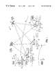
- the communication system 10includes a national system operation center 12 which transmits data signals to, multiple satellite transmitters and multiple terrestrial transmitters.
- the multiple satellite transmittersincludes a first bent pipeline satellite transmitter 14 and second bent pipeline satellite transmitter 16 .
- the terrestrial transmittersincludes a first terrestrial transmitter 18 , a second terrestrial transmitter 20 , and a third terrestrial transmitter 22 . While two (2) satellite transmitters 14 and 16 and three (3) terrestrial transmitters 18 to 22 are shown, it will be appreciated by those skilled in the art that various combinations or numbers of transmitters, including only satellite transmitters or terrestrial transmitters may be utilized.
- the system operation center 12preferably transmits audio data signals to the satellite transmitters 14 and 16 , via an antenna 24 , utilizing an RF carrier signal, such as C-band or X-band, which have a frequency range between about 5 GHz to about 12 GHz.
- Each satellite transmitter 14 and 16receives at antenna 26 , the modulated audio data signals, via an RF carrier signal relay 28 .
- the bent pipeline satellite transmitters 14 and 16will preferably down convert the RF carrier signal by mixing it with its own oscillating frequency to provide a RF broadcast carrier signal in S-band which has a frequency of about 2 GHz.
- the frequency bands set forth hereinare merely exemplary in nature and it will be understood that any type of frequency band available may be used.
- Each satellite transmitter 14 and 16retransmits or broadcasts the audio data signals received from the system operation center 12 into its corresponding overlapping coverage area or region 30 , via antennas 26 .
- Each overlapping coverage area 30 covered by each satellite transmitter 14 and 16is preferably the continental United States and the use of the two (2) satellite transmitters 14 and 16 provides redundancy substantially throughout the overlapping coverage areas 30 in order to provide for any unforeseen difficulties with either of the satellites 14 and 16 . Should different overlapping coverage areas be desired that are smaller or larger, a different number of satellites may be used for such coverage areas.
- the system operation center 12further transmits the audio data signals, preferably in digital form as opposed to an RF carrier signal, to each of the terrestrial transmitters 18 to 22 , via a relay 32 , using a digital fiberoptic link.
- point-to-point microwave transmissionmay also be utilized should the particular terrestrial transmitter be close enough in proximity to the system operation center 12 or any other appropriate transmission medium.
- Each terrestrial transmitter 18 to 22modulates the digital audio data signals on the same RF broadcast carrier signal or frequency band that the satellite transmitters 14 and 16 use, such as S-band (2 GHz).
- Each of the terrestrial transmitters 18 to 22may rebroadcast the audio data signals received from the system operation center 12 or audio data signals generated at a separate local system operation center where the particular terrestrial transmitter is located.
- Each of the terrestrial transmitters 18 to 22broadcasts into its respective coverage area 34 , 36 and 38 , which may be spatially separate from one another and all within the coverage areas 30 .
- Various mobile receivers 40 in vehicles 42 operating within coverage areas 30are operable to receive the modulated audio data signals from the satellite transmitters 14 and 16 , via antenna 44 .
- the mobile receivers 40are also operable to receive the modulated audio data signals from any of the terrestrial transmitters 18 to 22 , should the mobile receiver 40 be located in any of the coverage areas 34 to 38 .
- Each of the mobile receivers 40is operable to receive audio data signals from each of the transmitters substantially simultaneously in a time division multiplex (TDM) manner.
- TDMtime division multiplex
- the mobile receivers 40are each configured to receive three (3) transmitter signals substantially simultaneously over a TDM repeat interval, that each satellite transmitter 14 and 16 is configured to: transmit twenty (20) national broadcast audio channel signals, and each terrestrial transmitter 18 to 22 is configured to either broadcast five (5) local broadcast audio channel signals or the twenty (20) national broadcast audio channel signals.
- a 1 second receiver time block or TDM repeat intervalis divided into 3 separate transmitter time blocks, each of which is 0.333 seconds, with the first satellite transmitter 14 having a first transmitter time block S 1 , the second satellite transmitter 16 having a second transmitter time block S 2 and each of the terrestrial transmitters 18 to 22 having a third transmitter time block T n allocated or shared by all the terrestrial transmitters 18 to 22 which are shown spatially separated to allow for spectrum re-use.
- Receiver 40 in vehicle 42 within coverage area 34is operable to receive audio signals from satellite transmitter 14 , satellite transmitter 16 , and terrestrial transmitter 18 in a time division multiplex (TDM) matter.
- TDMtime division multiplex
- receiver time block 46audio data signals within TDM bursts or time blocks S 1 , S 2 and T 1 from satellite transmitter 14 , satellite transmitter 16 and terrestrial transmitter 18 , respectively, are shown being received by receiver 40 with a varying guard time 48 located at the beginning of each TDM burst or time block S 1 , S 2 and T 1 .
- the maximum guard time 48 showis equal to the maximum: time-of-arrival variation between the adjacent transmitters.
- time block S 1is shown farther to the left in the receiver time block 46 because satellite transmitter 14 is closer to mobile receiver 40 within coverage area 34 .
- Time block S 2is shown with a large guard time 48 between S 1 and S 2 because of the additional time it takes for mobile receiver 40 , within coverage area 34 , to receive the audio data signals (S 2 ) from satellite transmitter 16 .
- Time block T 1is shown with a smaller guard time 48 which varies depending on the location of the terrestrial transmitter 18 relative to the satellite transmitters 14 and 16 .
- receiver time block 50it can be seen that mobile receiver 40 , within coverage area 30 , only receives audio signals from the satellite transmitters 14 and 16 (S 1 and Here, the guard time 48 is larger before time block Si because of the additional time it takes for the audio data signals from satellite transmitter 14 to reach this mobile receiver 40 and the guard time 48 before time block S 2 is smaller because of the less time it takes for the audio data signals from satellite transmitter 16 to reach this mobile receiver 40 .
- time block Siis shown farther to the right which graphically shows the additional delay in the mobile receiver 40 receiving the audio data signals from satellite transmitter 14 , whereas the guard time 48 between time blocks S 1 and S 2 is very narrow in this location because of the positioning of satellite transmitter 16 which is in close proximity to the mobile receiver 40 in coverage area 36 .
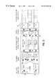
- FIG. 2a detailed schematic block diagram of a channel coding/transmission system 54 forming a portion of TDM communication system 10 according to a first preferred embodiment of the present invention as shown.
- the channel coding/transmission system 54may be located within the system operation center 12 , the satellite transmitters 14 and 16 or the terrestrial transmitters 18 to 22 depending on the particular configuration utilized and further discussed herein.
- the channel coding/transmission system 54includes a channel coding section 56 and a waveform generation section 58 which transmits the audio data signals, via transmitters 60 .
- the channel coding section 56includes a plurality of error correction encoders 62 .
- Each encoder 62includes an input 64 which receives a digital audio data signal and a plurality of outputs 66 , the number of which relate to the number of transmitters 60 being utilized substantially simultaneously.
- the error correction encoders 62are conventional error correction encoders which use error correction coding to expand the digital audio data signal or data bits received at input 64 by an encoder rate.
- a one-twelfth ( ⁇ fraction (1/12) ⁇ ) rate encoder 62is selected, such that each digital audio data bit through the encoder 62 will be expanded to twelve (12) audio code bits with four (4) of the code bits being delivered from each output 66 .
- the expanded code bitsare then applied to a plurality of first time multiplexers 68 , via inputs 70 , which time multiplex by channel.
- the number of time multiplexers 68depends on the number of transmitters 60 being used substantially simultaneously and the number of inputs 70 to the time multiplexers 68 depends on the number of encoders 62 or N channels being encoded.
- Each time multiplexer 68obtains four (4) code bits from each encoder 62 and adds them together in time to create a TDM channel data stream or first level of time division multiplexing (TDM) in the communication system 10 .
- TDMtime division multiplexing
- the time multiplexers 68each have a single output 72 that outputs the time division multiplexed audio code bits or TDM channel data stream which have been encoded, similar, to that shown in the TDM timeline of FIG. 4 (i.e. channel 1 , channel 2 . . . , channel N, channel 1 . . . , channel N).
- the time division multiplexed audio code bits from the channel coding section 56is applied to the waveform generation section 58 which includes a plurality of second time multiplexers 74 and a plurality of modulators 76 .
- the number of time multiplexers 74 and modulators 76depends on the number of transmitters 60 being utilized substantially simultaneously in the communication system 10 .
- the time multiplexers 74create the second level of time division multiplexing (TDM) in the communication system 10 .
- Each time multiplexer 74includes an input 78 which receives the encoded time division multiplexed audio channels or TDM channel data streams from time multiplexers 68 and an output 80 . Assuming that the audio code bits from each time multiplexer 68 is being received at a rate of one mega bit per second (1 Mbps), each time multiplexer 74 will multiply this rate by a predetermined value to increase the bit transfer rate.
- the output bit transfer rate of the time multiplexer 74will be three (3) times the input bit transfer rate in order to transmit all of the information in one-third the time.
- the time multiplexer 74will therefore, increase the output bit rate to 3 Mbps and send out a TDM burst of coded audio bits.
- each time multiplexer 74With a receiver time block of 1 second, each time multiplexer 74 will transfer its coded audio bits for 0.333 seconds, with each time multiplexer 74 operating on a one-third duty cycle.
- the first time multiplexer 74will thus be on for the first one-third second and will be able to transfer all of its coded audio bits because of the increased bit rate with the second and third time multiplexers 74 following thereafter.
- This relationshipis shown graphically to the right of FIG. 2 which shows each of the transmitters 60 transmitting TDM bursts of audio data in a time division multiplex manner with the audio data within the TDM bursts also being time division multiplexed, thereby creating two levels of time division multiplexing within the communication system 10 .
- Each modulator 76is a conventional modulator using a common modulation technique, such as PSK, FSK, QAM, etc.
- Each modulator 76takes the coded audio bits from the time multiplexers 74 and modulates the coded audio data bits onto an RF carrier signal in the particular signal format selected.
- the modulated RF carrier signalsare delivered to transmitters 60 , via outputs 84 .
- the RF carrier signalsare then transmitted or broadcast by the transmitters 60 which may include the satellite transmitters 14 and 16 or the terrestrial transmitters 18 to 22 , shown in FIG. 1 .
- Each modulator 76also inserts a synchronization field and a header field into each TDM burst or time block transmitted, further discussed herein.
- a TDM timeline 86is shown which identifies each TDM data burst 88 or time block from each of the transmitters 60 , shown in FIGS. 1 and 2.
- Each TDM burst 88 which forms the TDM repeat intervalincludes the guard time 48 which is a period when no data is sent.
- the maximum guard time 48is equal to the maximum time of arrival variation between adjacent transmitters. In other words, referring to FIG. 1, should satellite transmitter 14 be positioned on the west coast, and satellite transmitter 16 be positioned on the east coast, with the mobile receiver 40 being located on the west coast, the difference in time between receiving the data from the satellite transmitter 14 and the satellite transmitter 16 would be the maximum guard time 48 required for the communication system 10 .
- the guard time 48is preferably 9 milliseconds or +/ ⁇ 4.5 milliseconds on either end of the TDM burst 88 .
- the guard time 48will, of course, vary depending on the size of the coverage areas selected.
- the synchronization field 90is used by the mobile receiver 40 to synchronize both time and frequency with each of the transmitters 60 .
- the synchronization field 90includes phase and frequency information for each transmitter 60 .
- the header 92 of each TDM burst 88includes a transmitter ID, a pipeline queue and a data dimension.
- the transmitter IDidentifies the transmitter 60 (#1, #2, #3) from which the TDM burst 88 originated with.
- the pipeline queueidentifies where in a parallel pipeline or memory, the TDM burst 88 should be routed.
- the data dimensionidentifies the N number of audio channels and the number of times the N channels will repeat which is essentially the size of the TDM burst 88 .
- Portion 94diagrammatically identifies the time division multiplexed channel data or TDM channel data stream being transmitted by each transmitter 60 within the TDM burst 88 .
- the TDM bursts 88 or coded audio data bits from each of the transmitters 60may be redundant audio data or unique audio data. It should be noted that reference to redundant signals does not mean that the TDM data bursts 88 transmitted from each transmitter 60 are the same coded audio data bits, since the coded audio data bits from each channel are uniquely encoded and then time multiplexed by channel and by transmitter.
- the receiver 40uses a time division multiple access (TDMA) receiver 96 which receives the TDM bursts 88 from transmitters 60 , via antenna 44 .
- the TDMA receiver 96may be formed from any conventional TDMA receiver and is operable to receive time division multiplex signals from the multiple transmitters 60 in a time division multiplexed manner.
- the TDMA receiver 96receives the TDM bursts 88 on the modulated RF carrier signal and employs a conventional demodulator to strip or remove the RF carrier signal to convert the RF carrier signal containing the TDM burst 88 into only coded audio data bits.
- a portion of the coded audio data bitsare distributed in a symbol pipeline 98 , which is a memory buffer within the receiver 40 , via a switch or memory pointer 100 depending on which audio channel has been selected, via channel selection 102 .
- Switch 100allocates where the coded data bits will be routed in the parallel pipeline 98 , via queue selection 104 .
- Coded audio data bits from transmitter #1is put into a first parallel queue 106
- coded audio data bits from transmitter #2is put into a second parallel queue 108
- coded audio data bits from transmitter #3is put into a third parallel queue 110 .
- the switch or pointer 100selects where the TDM bursts 88 are routed depending on which pipeline queue is identified in the header portion 92 of the TDM burst 88 .
- the TDMA receiver 96when each TDM burst 88 is received by the TDMA receiver 96 , the TDMA receiver 96 will use the synchronization field 90 to time and frequency synchronize with the specific transmitter 60 .
- the TDMA receiver 96may also be configured to have an acquisition memory to retain the prior synchronization field for the particular transmitter. In this way, when a subsequent TDM burst 88 from a transmitter 60 is received, the TDMA receiver 96 will already be substantially in sync with the transmitter 60 .
- a decoder 112receives, at a continuous rate, a vector 114 of coded audio data bits representing a single audio data bit.
- the decoder 112decodes this vector 114 to generate the decoded audio data bits for the particular channel selected from a user, via selection 102 .
- the coded audio data bits in the symbol pipeline 98is only the coded audio data bits for the particular channel selected.
- the channel coding/transmission system 54is shown configured to encode and transmit N channels with three transmitters, two of which are the satellite transmitters 14 and 16 and one of which is the terrestrial transmitter 18 .
- the encoders 62 , time multiplexers 68 , and time multiplexers 74 and modulators 76 for the satellite transmitters 14 and 16are all located within the system operation center 12 .
- the relay to satellite transmitters 28are the RF carrier signals to the satellite transmitters 14 and 16 , via antenna 24 , and the relay to terrestrial transmitter 32 is preferably the digital fiberoptic link and, is therefore, transmitted digitally before being time multiplexed by time multiplexer 74 and modulated by modulator 76 located at terrestrial transmitter 18 .
- each satellite transmitter 14 and 16 and the terrestrial transmitter 18preferably transmits the same channels 1 to N which are national broadcast channels in overlapping coverage areas. Accordingly, the receiver 40 will receive redundant national broadcast station information, each of which is separately encoded and time division multiplexed at two levels, thereby providing for a more robust signal.
- Such a configurationwill generally be set up in an urban environment where tall buildings may block signals from the satellite transmitters 14 and 16 .
- the channel coding/transmission system 54is shown configured to encode both national broadcast channels and local broadcast channels and transmit the encoded channel data with the two satellite transmitters 14 and 16 and the terrestrial transmitter 18 .
- the encoders 62 , time multiplexers 68 , time multiplexers 74 and modulators 76 for the satellite transmitters 14 and 16are all located within the system operation center 12 .
- the relay to satellite transmitters 28are the RF carrier signals transmitted to satellite transmitters 14 and 16 , via antenna 24 and the relay to terrestrial transmitter 32 is preferably the: digital fiberoptic link and is thus transmitted digitally to a local system operation center 116 which houses terrestrial transmitter 18 .
- the local operation center 116also includes encoders 62 , time multiplexers 68 , time multiplexers 74 and a modulator 76 .
- the local operation center 116further includes a time multiplexer 118 which time multiplexes the channel set for the national channels and the channel set for the local channels together into channels 1 to M.
- the time multiplexers 74have delays 0 , D 1 and D 2 which vary depending on the number of multiplexed channel data to be transmitted.
- the time multiplexer 74 in the system operation center 12will need to transmit channels 1 to N while the time multiplexer 74 in the local operation center 116 will be required to transfer channels 1 to M which include channels 1 to N, therefore requiring a longer delay to D 2 .
- the rate and duty cyclewill also correspondingly change depending on the delays selected for each multiplexer 74 .
- the local operation center 116may either use an open loop or a closed loop synchronization.
- both the system operation center 12 : and the local operation center 116can predetermine the allocated time slots for its corresponding transmitters based upon a known timing system, such as the atomic standard time or the global positioning sensor (GPS) timing.
- a known timing systemsuch as the atomic standard time or the global positioning sensor (GPS) timing.
- the local operation center 116may also utilize a closed loop synchronization technique by utilizing a separate receiver to monitor the TDM bursts 88 from satellite transmitters 14 and 16 in order to determine when its time slot becomes available to transmit with the terrestrial transmitter 18 .
- the system 54may also be configured to transmit only local broadcasting channels from terrestrial transmitters broadcasting into overlapping local coverage areas. Such a versatile system 10 also will enable the system 10 to be brought up with only terrestrial transmitters initially where each transmitter will be a terrestrial transmitter and subsequently configured to include satellite transmitters, as the satellite transmitters are added to the system 10 which will be transparent to the receiver 40 .
- the mobile receiver 40is selecting a national broadcast channel, via selection 102 , and the transmitters include satellite transmitters 14 and 16 which are transmitting only the national broadcast signals and terrestrial transmitter 18 which is only broadcasting local stations.
- the TDMA receiver 96With the TDMA receiver 96 tuned to a national broadcast channel, the TDMA receiver 96 will only transfer the coded audio data bits for the channel selected to fill the first parallel queue 106 and the second parallel queue 108 of symbol pipeline 98 .
- the decoder 112thereby selects the vector 114 or column of data from the symbol pipeline 98 which includes coded data bits from satellite transmitters 14 and 16 which each carry redundant channel data or information that is encoded differently.
- the receiver 40is shown with the TDMA receiver 96 tuned to a local broadcast channel, via selection 102 , with transmitter #1 being the satellite transmitter 14 and transmitter #2 being the satellite transmitter 16 and transmitter #3 being the terrestrial transmitter 18 that is transmitting the local broadcast channels.
- the symbol pipeline 98is only filled with the local broadcast channel that is selected by selection 102 , which is dumped into the third parallel queue 110 , via switch 100 .
- the decoder 112selects the vector 114 as the parallel queue 110 fills to decode only the selected audio coded bits from the terrestrial transmitter 18 which still has redundancy since the data from the terrestrial transmitter 18 is also encoded.
- FIGS. 9 and 10the channel coding/transmission system 54 and the receiver 40 according to the teachings of a second preferred embodiment in the present invention are shown.
- the channel coding/transmission system 54 and the receiver 40are substantially similar with respect to the first preferred embodiment of the present invention, except that the channel coding/transmission system 54 includes weighted interleavers 120 and the receiver 40 includes weighted deinterleavers 122 .
- the weighted interleaver 120randomly or non-uniformly distributes the expanded data bits in time between a minimum delay and a maximum delay to provide optimum decorrelation. In other words, the weighted interleavers 120 will route the expanded data bits pseudo randomly according to a non-uniform probability distribution from a minimum delay to a maximum delay.
- the weighted interleavers 120 and the weighted deinterleavers 122are discussed in detail in application Ser. No. 08/864,774, filed May 29, 1997, entitled “COMMUNICATION SYSTEM FOR BROADCASTING TO MOBILE USERS”, naming as inventors Scott Adam Stephens, Terrence Raymond Smigla and Donald Ray Martin (TRW Docket No. 35-0005) and in U.S. Ser. No. 08/864,755, filed May 29, 1997, entitled “WEIGHTED INTERLEAVING FOR CORRELATED CHANNEL CODING”, also naming as inventors Scott Adam Stephens, Terrence Raymond Smigla and Donald Ray Martin (TRW Docket No. 35-004), each of which are hereby incorporated by reference.
- the interleavers 120 and deinterleavers 122may be conventional block or convolutional interleavers and deinterleavers.
- the weighted deinterleavers 122operates complimentary to the weighted interleavers 120 to unshuffle the coded data bits so that the coded data bits are aligned substantially similar to the coded data bits received by the weighted interleaver 120 . This is shown graphically in the symbol pipeline 98 where each parallel queue 106 , 108 and 110 are pseudo randomly filled, with the very right side of the symbol pipeline 98 or memory being filled prior to a vector 114 being decoded by the decoder 112 .
- the TDM communication system 10thus allocates a TDM time block to each transmitter having a guard time around each time block for propagation time delay variations between the transmitters utilized. This allows the same or different information to arrive at a single receiver from multiple transmitters broadcasting in overlapping coverage areas substantially simultaneously.
- a single time blockmay be allocated to all terrestrial transmitters which have spatially separated coverage areas from one another, thereby allowing spectrum reuse, while simultaneously reserving separate time blocks for the satellite transmitters having overlapping coverage areas which also overlap the terrestrial transmitter coverage areas.
- a receiver utilizing a single frequency bandcan for example, receive two (2) satellite signals and a local terrestrial broadcast signal simultaneously, each with possibly different content.
- the systemcould also be dynamic in its allocation of time blocks to each transmitter.
- the terrestrial transmittermay operate dynamically to transmit both national broadcast channels, as well as local broadcast channels when either of the particular channels are available.
- the terrestrial transmittersmay also be configured to transmit only local broadcast channels. Since the time synchronization and data stream information are contained in each TDM block header, the receiver is also able to operate even when all but one transmitter are not present.
- This systemprovides the advantage that separate frequency bands are not required for multiple transmitters to reach a single receiver, with each transmitter sending different information. Any broadcast scenario where multiple transmitters of the same or different information are employed can use this communication system. This is especially true of any system which may deploy transmitters at different times where the allocation of bandwidth is dynamic and the receiver does not require the entire spectrum to be filled for operation.
- one such communication systemmay consist of two satellite transmitters and many terrestrial transmitters broadcasting digital audio programming.
- the broadcastingmay initially start from only terrestrial transmitters in a few large cities having locally overlapping coverage areas.
- Each transmitter groupmay broadcast separate channels to local receivers, since these locally overlapping regions are spatially separate from other locally overlapping regions.
- each satelliteWhen the satellites become operational, each satellite may then be allocated a large portion of the available bandwidth for national broadcasting while a single time block can be reserved for the local terrestrial broadcasts.
- the terrestrial transmitterscan also serve another purpose. By dynamically allocating a portion of the national bandwidth for news or local programming or to retransmit part of the satellite information for information redundancy. This data is used by the receiver to form an audio stream with greater veracity, such as in urban environments where satellite signals may be degraded.
Landscapes
- Engineering & Computer Science (AREA)
- Physics & Mathematics (AREA)
- Astronomy & Astrophysics (AREA)
- Aviation & Aerospace Engineering (AREA)
- General Physics & Mathematics (AREA)
- Computer Networks & Wireless Communication (AREA)
- Signal Processing (AREA)
- Time-Division Multiplex Systems (AREA)
- Radio Relay Systems (AREA)
- Mobile Radio Communication Systems (AREA)
Abstract
Description
Claims (25)
Priority Applications (3)
| Application Number | Priority Date | Filing Date | Title |
|---|---|---|---|
| US09/095,486US6519262B1 (en) | 1998-06-10 | 1998-06-10 | Time division multiplex approach for multiple transmitter broadcasting |
| EP99110982AEP0977376B1 (en) | 1998-06-10 | 1999-06-09 | A time division multiplex approach for multiple transmitter broadcasting |
| DE69933622TDE69933622T2 (en) | 1998-06-10 | 1999-06-09 | A time division multiplex approach for broadcasting with multiple transmitters |
Applications Claiming Priority (1)
| Application Number | Priority Date | Filing Date | Title |
|---|---|---|---|
| US09/095,486US6519262B1 (en) | 1998-06-10 | 1998-06-10 | Time division multiplex approach for multiple transmitter broadcasting |
Publications (1)
| Publication Number | Publication Date |
|---|---|
| US6519262B1true US6519262B1 (en) | 2003-02-11 |
Family
ID=22252230
Family Applications (1)
| Application Number | Title | Priority Date | Filing Date |
|---|---|---|---|
| US09/095,486Expired - LifetimeUS6519262B1 (en) | 1998-06-10 | 1998-06-10 | Time division multiplex approach for multiple transmitter broadcasting |
Country Status (3)
| Country | Link |
|---|---|
| US (1) | US6519262B1 (en) |
| EP (1) | EP0977376B1 (en) |
| DE (1) | DE69933622T2 (en) |
Cited By (32)
| Publication number | Priority date | Publication date | Assignee | Title |
|---|---|---|---|---|
| US20020113801A1 (en)* | 2000-11-29 | 2002-08-22 | Maire Reavy | System and method for improving the readability of text |
| US20040032878A1 (en)* | 2002-08-13 | 2004-02-19 | Rockwell Collins, Inc. | Waveform for virtually simultaneous transmission and multiple receptions system and method |
| US20050021737A1 (en)* | 2003-05-01 | 2005-01-27 | Ellison Carl M. | Liveness protocol |
| US6879808B1 (en)* | 2000-11-15 | 2005-04-12 | Space Systems/Loral, Inc | Broadband communication systems and methods using low and high bandwidth request and broadcast links |
| US20050220147A1 (en)* | 2002-02-14 | 2005-10-06 | Harri Pekonen | Retransmission of a burst copy in a broadband digital network |
| US20060209756A1 (en)* | 2001-01-03 | 2006-09-21 | Zoran Kostic | Combined simulcasting and dedicated services in a wireless communication system |
| US7313358B1 (en)* | 2002-06-08 | 2007-12-25 | Christopher P Ricci | Communication system for redirecting communication with radio frequency devices |
| WO2008006246A1 (en)* | 2006-07-06 | 2008-01-17 | Daoben Li | A time division multiplexing method and system |
| US20090070833A1 (en)* | 1999-11-23 | 2009-03-12 | Gofigure, L.L.C.A Missouri Limited Liability Company | System and method for providing digital video to a wireless communications device |
| US7508887B1 (en) | 2005-09-06 | 2009-03-24 | Rockwell Collins, Inc. | Signal acquisition with transmit blanking compensation |
| US20100120417A1 (en)* | 2008-11-07 | 2010-05-13 | Qualcomm Incorporated | Regionalized delivery of hybrid mobile broadcast services or channels in a mobile broadcast network |
| US20100217523A1 (en)* | 2007-09-13 | 2010-08-26 | Cpmtomemta; Teves AG & Co. oHG | Safety-critical updating of maps via a data channel of a satellite navigation system |
| US7835427B1 (en) | 2007-03-30 | 2010-11-16 | Rockwell Collins, Inc. | Multiplexed architecture for simultaneous transmission and reception |
| US7839900B1 (en) | 2006-09-29 | 2010-11-23 | Rockwell Collins, Inc. | Method and architecture for TTNT symbol rate scaling modes |
| US20110065377A1 (en)* | 2009-09-11 | 2011-03-17 | Lazer Spots, Llc | Equipment, system and methodologies for segmentation of listening area into sub-areas enabling delivery of localized auxiliary information |
| US20110141918A1 (en)* | 2009-09-13 | 2011-06-16 | Research Institute Of Tsinghua University In Shenzhen | Time division multiplexing method and system |
| US7970947B1 (en) | 2005-03-10 | 2011-06-28 | Rockwell Collins, Inc. | Tactical targeting network technology small form factor user system |
| US20140372756A1 (en)* | 1999-09-20 | 2014-12-18 | Security First Corp. | Secure data parser method and system |
| US9009848B2 (en) | 2004-10-25 | 2015-04-14 | Security First Corp. | Secure data parser method and system |
| US9215218B2 (en) | 2008-02-22 | 2015-12-15 | Security First Corp. | Systems and methods for secure workgroup management and communication |
| US9213857B2 (en) | 2010-03-31 | 2015-12-15 | Security First Corp. | Systems and methods for securing data in motion |
| US9232481B1 (en) | 2009-09-11 | 2016-01-05 | Geo-Broadcast Solutions, Llc | Equipment, system and methodologies for robust coverage in a broadcast area |
| US9264224B2 (en) | 2010-09-20 | 2016-02-16 | Security First Corp. | Systems and methods for secure data sharing |
| US9411524B2 (en) | 2010-05-28 | 2016-08-09 | Security First Corp. | Accelerator system for use with secure data storage |
| US9516002B2 (en) | 2009-11-25 | 2016-12-06 | Security First Corp. | Systems and methods for securing data in motion |
| US9733849B2 (en) | 2014-11-21 | 2017-08-15 | Security First Corp. | Gateway for cloud-based secure storage |
| CN107637149A (en)* | 2015-04-10 | 2018-01-26 | 西格弗克斯公司 | Method for transmitting broadcast singal in a wireless communication system |
| US9881177B2 (en) | 2013-02-13 | 2018-01-30 | Security First Corp. | Systems and methods for a cryptographic file system layer |
| US10206196B2 (en) | 2014-10-23 | 2019-02-12 | At&T Intellectual Property I, L.P. | Dynamic wireless multicast orthogonal frequency division multiple access architecture |
| EP3437218A4 (en)* | 2016-03-29 | 2020-01-01 | GatesAir, Inc. | TIME MULTIPLEXED SPECTRATION |
| CN111698023A (en)* | 2015-07-02 | 2020-09-22 | 高通股份有限公司 | Method and apparatus for efficient data transmission in half-duplex communication system with large propagation delay |
| US12093412B2 (en) | 2005-11-18 | 2024-09-17 | Security First Innovations, Llc | Secure data parser method and system |
Families Citing this family (4)
| Publication number | Priority date | Publication date | Assignee | Title |
|---|---|---|---|---|
| EP1316233B1 (en) | 2000-08-02 | 2011-10-05 | ATC Technologies, LLC | Coordinated frequency reuse of a terrestrial and a satellite system. |
| US6859652B2 (en) | 2000-08-02 | 2005-02-22 | Mobile Satellite Ventures, Lp | Integrated or autonomous system and method of satellite-terrestrial frequency reuse using signal attenuation and/or blockage, dynamic assignment of frequencies and/or hysteresis |
| US7792488B2 (en) | 2000-12-04 | 2010-09-07 | Atc Technologies, Llc | Systems and methods for transmitting electromagnetic energy over a wireless channel having sufficiently weak measured signal strength |
| CN113131984B (en)* | 2019-12-31 | 2022-12-02 | 大唐移动通信设备有限公司 | Method and device for indicating satellite coverage information |
Citations (13)
| Publication number | Priority date | Publication date | Assignee | Title |
|---|---|---|---|---|
| US3927269A (en)* | 1972-12-29 | 1975-12-16 | Japan Broadcasting Corp | Time division multiplexing transmission system |
| US4245339A (en)* | 1978-04-29 | 1981-01-13 | Telefonbau Und Normalzeit, Gmbh | Telecommunication switching network having a multistage reversed trunking scheme |
| US5006855A (en)* | 1986-08-20 | 1991-04-09 | The Mitre Corporation | Ranging and processing system for mobile surveillance and data link |
| US5448621A (en)* | 1993-08-02 | 1995-09-05 | Motorola, Inc. | Dynamic reallocation of spectral capacity in cellular communication systems |
| US5483541A (en) | 1993-09-13 | 1996-01-09 | Trw Inc. | Permuted interleaver |
| US5539730A (en)* | 1994-01-11 | 1996-07-23 | Ericsson Ge Mobile Communications Inc. | TDMA/FDMA/CDMA hybrid radio access methods |
| US5584046A (en)* | 1994-11-04 | 1996-12-10 | Cornell Research Foundation, Inc. | Method and apparatus for spectrum sharing between satellite and terrestrial communication services using temporal and spatial synchronization |
| US5592471A (en) | 1995-04-21 | 1997-01-07 | Cd Radio Inc. | Mobile radio receivers using time diversity to avoid service outages in multichannel broadcast transmission systems |
| US5600672A (en)* | 1991-03-27 | 1997-02-04 | Matsushita Electric Industrial Co., Ltd. | Communication system |
| US5875214A (en)* | 1995-02-17 | 1999-02-23 | Alcatel Telspace | Device for initializing a viterbi decoder in a receiver for signals transmitted in the form of bursts, corresponding receiver and corresponding initialization method |
| US5966377A (en)* | 1996-05-20 | 1999-10-12 | Mitsubishi Denki Kabushiki Kaisha | Spread spectrum communication system |
| US5978366A (en)* | 1996-12-20 | 1999-11-02 | Ericsson Inc. | Methods and systems for reduced power operation of cellular mobile terminals |
| US6092165A (en)* | 1996-08-16 | 2000-07-18 | Unisys Corporation | Memory control unit using a programmable shift register for generating timed control signals |
Family Cites Families (3)
| Publication number | Priority date | Publication date | Assignee | Title |
|---|---|---|---|---|
| JPS61120538A (en)* | 1984-11-15 | 1986-06-07 | Nec Corp | Multi-direction multiplex communication equipment |
| FI91345C (en)* | 1992-06-24 | 1994-06-10 | Nokia Mobile Phones Ltd | A method for enhancing handover |
| JP2809179B2 (en)* | 1996-03-14 | 1998-10-08 | 日本電気株式会社 | Radio broadcast communication system |
- 1998
- 1998-06-10USUS09/095,486patent/US6519262B1/ennot_activeExpired - Lifetime
- 1999
- 1999-06-09DEDE69933622Tpatent/DE69933622T2/ennot_activeExpired - Fee Related
- 1999-06-09EPEP99110982Apatent/EP0977376B1/ennot_activeExpired - Lifetime
Patent Citations (13)
| Publication number | Priority date | Publication date | Assignee | Title |
|---|---|---|---|---|
| US3927269A (en)* | 1972-12-29 | 1975-12-16 | Japan Broadcasting Corp | Time division multiplexing transmission system |
| US4245339A (en)* | 1978-04-29 | 1981-01-13 | Telefonbau Und Normalzeit, Gmbh | Telecommunication switching network having a multistage reversed trunking scheme |
| US5006855A (en)* | 1986-08-20 | 1991-04-09 | The Mitre Corporation | Ranging and processing system for mobile surveillance and data link |
| US5600672A (en)* | 1991-03-27 | 1997-02-04 | Matsushita Electric Industrial Co., Ltd. | Communication system |
| US5448621A (en)* | 1993-08-02 | 1995-09-05 | Motorola, Inc. | Dynamic reallocation of spectral capacity in cellular communication systems |
| US5483541A (en) | 1993-09-13 | 1996-01-09 | Trw Inc. | Permuted interleaver |
| US5539730A (en)* | 1994-01-11 | 1996-07-23 | Ericsson Ge Mobile Communications Inc. | TDMA/FDMA/CDMA hybrid radio access methods |
| US5584046A (en)* | 1994-11-04 | 1996-12-10 | Cornell Research Foundation, Inc. | Method and apparatus for spectrum sharing between satellite and terrestrial communication services using temporal and spatial synchronization |
| US5875214A (en)* | 1995-02-17 | 1999-02-23 | Alcatel Telspace | Device for initializing a viterbi decoder in a receiver for signals transmitted in the form of bursts, corresponding receiver and corresponding initialization method |
| US5592471A (en) | 1995-04-21 | 1997-01-07 | Cd Radio Inc. | Mobile radio receivers using time diversity to avoid service outages in multichannel broadcast transmission systems |
| US5966377A (en)* | 1996-05-20 | 1999-10-12 | Mitsubishi Denki Kabushiki Kaisha | Spread spectrum communication system |
| US6092165A (en)* | 1996-08-16 | 2000-07-18 | Unisys Corporation | Memory control unit using a programmable shift register for generating timed control signals |
| US5978366A (en)* | 1996-12-20 | 1999-11-02 | Ericsson Inc. | Methods and systems for reduced power operation of cellular mobile terminals |
Non-Patent Citations (1)
| Title |
|---|
| Overview of Techniques for Mitigation of Fading and Shadowing in the Direct Broadcast Satellite Radio Environment, David Bell, John Gevargiz, Arvydas Vaisnys and David Julian. |
Cited By (70)
| Publication number | Priority date | Publication date | Assignee | Title |
|---|---|---|---|---|
| US20140372756A1 (en)* | 1999-09-20 | 2014-12-18 | Security First Corp. | Secure data parser method and system |
| US9298937B2 (en)* | 1999-09-20 | 2016-03-29 | Security First Corp. | Secure data parser method and system |
| US9449180B2 (en) | 1999-09-20 | 2016-09-20 | Security First Corp. | Secure data parser method and system |
| US9613220B2 (en) | 1999-09-20 | 2017-04-04 | Security First Corp. | Secure data parser method and system |
| US7778636B2 (en) | 1999-11-23 | 2010-08-17 | Gofigure Media, Llc | Mobile advertising systems and methods |
| US8843947B2 (en) | 1999-11-23 | 2014-09-23 | Gofigure Media, Llc | Digital media distribution system and method |
| US8385912B2 (en) | 1999-11-23 | 2013-02-26 | Gofigure Media, Llc | Digital media distribution system |
| US20090070833A1 (en)* | 1999-11-23 | 2009-03-12 | Gofigure, L.L.C.A Missouri Limited Liability Company | System and method for providing digital video to a wireless communications device |
| US20090076892A1 (en)* | 1999-11-23 | 2009-03-19 | Gofigure, L.L.C., A Missouri Limited Liability Company | System, method and device for playing recorded music on a wireless communications device |
| US6879808B1 (en)* | 2000-11-15 | 2005-04-12 | Space Systems/Loral, Inc | Broadband communication systems and methods using low and high bandwidth request and broadcast links |
| US20020113801A1 (en)* | 2000-11-29 | 2002-08-22 | Maire Reavy | System and method for improving the readability of text |
| US7496062B2 (en)* | 2001-01-03 | 2009-02-24 | At&T Corp. | Combined simulcasting and dedicated services in a wireless communication system |
| US9807731B2 (en) | 2001-01-03 | 2017-10-31 | At&T Intellectual Property Ii, L.P. | Combined simulcasting and dedicated services in a wireless communication system |
| US20060209756A1 (en)* | 2001-01-03 | 2006-09-21 | Zoran Kostic | Combined simulcasting and dedicated services in a wireless communication system |
| US20050220147A1 (en)* | 2002-02-14 | 2005-10-06 | Harri Pekonen | Retransmission of a burst copy in a broadband digital network |
| US7313358B1 (en)* | 2002-06-08 | 2007-12-25 | Christopher P Ricci | Communication system for redirecting communication with radio frequency devices |
| US20040032878A1 (en)* | 2002-08-13 | 2004-02-19 | Rockwell Collins, Inc. | Waveform for virtually simultaneous transmission and multiple receptions system and method |
| US7830781B2 (en)* | 2002-08-13 | 2010-11-09 | Rockwell Collins, Inc. | Waveform for virtually simultaneous transmission and multiple receptions system and method |
| US20050021737A1 (en)* | 2003-05-01 | 2005-01-27 | Ellison Carl M. | Liveness protocol |
| US9871770B2 (en) | 2004-10-25 | 2018-01-16 | Security First Corp. | Secure data parser method and system |
| US9906500B2 (en) | 2004-10-25 | 2018-02-27 | Security First Corp. | Secure data parser method and system |
| US11178116B2 (en) | 2004-10-25 | 2021-11-16 | Security First Corp. | Secure data parser method and system |
| US9992170B2 (en) | 2004-10-25 | 2018-06-05 | Security First Corp. | Secure data parser method and system |
| US9338140B2 (en) | 2004-10-25 | 2016-05-10 | Security First Corp. | Secure data parser method and system |
| US9985932B2 (en) | 2004-10-25 | 2018-05-29 | Security First Corp. | Secure data parser method and system |
| US9935923B2 (en) | 2004-10-25 | 2018-04-03 | Security First Corp. | Secure data parser method and system |
| US9294445B2 (en) | 2004-10-25 | 2016-03-22 | Security First Corp. | Secure data parser method and system |
| US9009848B2 (en) | 2004-10-25 | 2015-04-14 | Security First Corp. | Secure data parser method and system |
| US9047475B2 (en) | 2004-10-25 | 2015-06-02 | Security First Corp. | Secure data parser method and system |
| US9294444B2 (en) | 2004-10-25 | 2016-03-22 | Security First Corp. | Systems and methods for cryptographically splitting and storing data |
| US9135456B2 (en) | 2004-10-25 | 2015-09-15 | Security First Corp. | Secure data parser method and system |
| US9177159B2 (en) | 2004-10-25 | 2015-11-03 | Security First Corp. | Secure data parser method and system |
| US7970947B1 (en) | 2005-03-10 | 2011-06-28 | Rockwell Collins, Inc. | Tactical targeting network technology small form factor user system |
| US7508887B1 (en) | 2005-09-06 | 2009-03-24 | Rockwell Collins, Inc. | Signal acquisition with transmit blanking compensation |
| US12141299B2 (en) | 2005-11-18 | 2024-11-12 | Security First Innovations, Llc | Secure data parser method and system |
| US12093412B2 (en) | 2005-11-18 | 2024-09-17 | Security First Innovations, Llc | Secure data parser method and system |
| WO2008006246A1 (en)* | 2006-07-06 | 2008-01-17 | Daoben Li | A time division multiplexing method and system |
| CN101479973B (en)* | 2006-07-06 | 2012-06-27 | 北京清深技术开发中心有限公司 | A time division multiplexing method and system |
| US7839900B1 (en) | 2006-09-29 | 2010-11-23 | Rockwell Collins, Inc. | Method and architecture for TTNT symbol rate scaling modes |
| US7835427B1 (en) | 2007-03-30 | 2010-11-16 | Rockwell Collins, Inc. | Multiplexed architecture for simultaneous transmission and reception |
| US9091554B2 (en)* | 2007-09-13 | 2015-07-28 | Continental Teves Ag & Co. Ohg | Safety-critical updating of maps via a data channel of a satellite navigation system |
| US20100217523A1 (en)* | 2007-09-13 | 2010-08-26 | Cpmtomemta; Teves AG & Co. oHG | Safety-critical updating of maps via a data channel of a satellite navigation system |
| US9215218B2 (en) | 2008-02-22 | 2015-12-15 | Security First Corp. | Systems and methods for secure workgroup management and communication |
| US8792899B2 (en)* | 2008-11-07 | 2014-07-29 | Qualcomm Incorporated | Regionalized delivery of hybrid mobile broadcast services or channels in a mobile broadcast network |
| US20100120417A1 (en)* | 2008-11-07 | 2010-05-13 | Qualcomm Incorporated | Regionalized delivery of hybrid mobile broadcast services or channels in a mobile broadcast network |
| US8862048B2 (en)* | 2009-09-11 | 2014-10-14 | Geo-Broadcast Solutions, Llc | Equipment, system and methodologies for segmentation of listening area into sub-areas enabling delivery of localized auxiliary information |
| US20110065377A1 (en)* | 2009-09-11 | 2011-03-17 | Lazer Spots, Llc | Equipment, system and methodologies for segmentation of listening area into sub-areas enabling delivery of localized auxiliary information |
| US9232481B1 (en) | 2009-09-11 | 2016-01-05 | Geo-Broadcast Solutions, Llc | Equipment, system and methodologies for robust coverage in a broadcast area |
| US20110141918A1 (en)* | 2009-09-13 | 2011-06-16 | Research Institute Of Tsinghua University In Shenzhen | Time division multiplexing method and system |
| US9516002B2 (en) | 2009-11-25 | 2016-12-06 | Security First Corp. | Systems and methods for securing data in motion |
| US9213857B2 (en) | 2010-03-31 | 2015-12-15 | Security First Corp. | Systems and methods for securing data in motion |
| US10068103B2 (en) | 2010-03-31 | 2018-09-04 | Security First Corp. | Systems and methods for securing data in motion |
| US9589148B2 (en) | 2010-03-31 | 2017-03-07 | Security First Corp. | Systems and methods for securing data in motion |
| US9443097B2 (en) | 2010-03-31 | 2016-09-13 | Security First Corp. | Systems and methods for securing data in motion |
| US9411524B2 (en) | 2010-05-28 | 2016-08-09 | Security First Corp. | Accelerator system for use with secure data storage |
| US9264224B2 (en) | 2010-09-20 | 2016-02-16 | Security First Corp. | Systems and methods for secure data sharing |
| US9785785B2 (en) | 2010-09-20 | 2017-10-10 | Security First Corp. | Systems and methods for secure data sharing |
| US10402582B2 (en) | 2013-02-13 | 2019-09-03 | Security First Corp. | Systems and methods for a cryptographic file system layer |
| US9881177B2 (en) | 2013-02-13 | 2018-01-30 | Security First Corp. | Systems and methods for a cryptographic file system layer |
| US10206196B2 (en) | 2014-10-23 | 2019-02-12 | At&T Intellectual Property I, L.P. | Dynamic wireless multicast orthogonal frequency division multiple access architecture |
| US10031679B2 (en) | 2014-11-21 | 2018-07-24 | Security First Corp. | Gateway for cloud-based secure storage |
| US9733849B2 (en) | 2014-11-21 | 2017-08-15 | Security First Corp. | Gateway for cloud-based secure storage |
| CN107637149B (en)* | 2015-04-10 | 2021-04-30 | 西格弗克斯公司 | Method for transmitting broadcast signal in wireless communication system |
| CN107637149A (en)* | 2015-04-10 | 2018-01-26 | 西格弗克斯公司 | Method for transmitting broadcast singal in a wireless communication system |
| CN111698023A (en)* | 2015-07-02 | 2020-09-22 | 高通股份有限公司 | Method and apparatus for efficient data transmission in half-duplex communication system with large propagation delay |
| CN111698023B (en)* | 2015-07-02 | 2022-05-27 | 高通股份有限公司 | Method, apparatus, and medium for determining guard time for half-duplex transceiver |
| EP3437218A4 (en)* | 2016-03-29 | 2020-01-01 | GatesAir, Inc. | TIME MULTIPLEXED SPECTRATION |
| US10666369B2 (en) | 2016-03-29 | 2020-05-26 | Gatesair, Inc. | Adaptive processing in time-multiplexed signals |
| US11258525B2 (en) | 2016-03-29 | 2022-02-22 | Gatesair, Inc. | Adaptive processing in time-multiplexed signals |
| US11683108B2 (en) | 2016-03-29 | 2023-06-20 | Gatesair, Inc. | Adaptive processing in time-multiplexed signals |
Also Published As
| Publication number | Publication date |
|---|---|
| EP0977376B1 (en) | 2006-10-18 |
| EP0977376A3 (en) | 2003-06-25 |
| EP0977376A2 (en) | 2000-02-02 |
| DE69933622T2 (en) | 2007-02-01 |
| DE69933622D1 (en) | 2006-11-30 |
Similar Documents
| Publication | Publication Date | Title |
|---|---|---|
| US6519262B1 (en) | Time division multiplex approach for multiple transmitter broadcasting | |
| US5864546A (en) | System for formatting broadcast data for satellite transmission and radio reception | |
| US5912917A (en) | Digital broadcast system | |
| US6876623B1 (en) | Tuning scheme for code division multiplex broadcasting system | |
| AU612253B2 (en) | Multiplexed address control in a tdm communication system | |
| EP2127408B1 (en) | Techniques for providing broadcast services on spot beam satellites | |
| US6249514B1 (en) | Satellite direct radio broadcast system | |
| JP4017987B2 (en) | Method and apparatus for concatenated convolutional encoding and interleaving | |
| US6185265B1 (en) | System for time division multiplexing broadcast channels with R-1/2 or R-3/4 convolutional coding for satellite transmission via on-board baseband processing payload or transparent payload | |
| US5867490A (en) | Direct radio broadcast receiver for providing frame synchronization and correlation for time division multiplexed transmissions | |
| US8750088B2 (en) | Efficient layered coding technique to mitigate shadowing in satellite propagation channel | |
| US6115366A (en) | System for managing space segment usage among broadcast service providers | |
| EP1990966A2 (en) | System and method of transmitting and receiving satellite digital radio signals over an ODD number of frequency slots | |
| JP2000269876A (en) | Method and apparatus for communication | |
| US6975600B1 (en) | Multimode transmission system using TDMA | |
| EP0944967B1 (en) | Digital satellite direct broadcast system | |
| US6333922B1 (en) | Satellite payload processing system for switching uplink signals to time division multiplexed downlink signals | |
| EP1030463B1 (en) | Tuning scheme for code division multiplex broadcasting system | |
| US7953367B2 (en) | System and method for efficient frequency use in a hybrid multi-spot satellite broadcasting system | |
| US6542480B1 (en) | Satellite payload processing system using polyphase demultiplexing, quadrature phase shift keying demodulation and rate alignment | |
| JP2000201118A (en) | Code dividing multiple satellite broadcast system | |
| US20130201895A1 (en) | Method for Automatic Reconfiguration in a Hierarchical Modulation System | |
| US6108319A (en) | Satellite payload processing system providing on-board rate alignment | |
| KR20210113798A (en) | Satellite IoT terminal and effective and robust unidirectional data transmission methods therby | |
| KR100492256B1 (en) | Satellite broadcasting repeater |
Legal Events
| Date | Code | Title | Description |
|---|---|---|---|
| AS | Assignment | Owner name:TRW INC., CALIFORNIA Free format text:ASSIGNMENT OF ASSIGNORS INTEREST;ASSIGNORS:STEPHENS, SCOTT A.;SMIGLA, TERRENCE R.;REEL/FRAME:009241/0997 Effective date:19980610 | |
| STCF | Information on status: patent grant | Free format text:PATENTED CASE | |
| AS | Assignment | Owner name:NORTHROP GRUMMAN CORPORATION, CALIFORNIA Free format text:ASSIGNMENT OF ASSIGNORS INTEREST;ASSIGNOR:TRW, INC. N/K/A NORTHROP GRUMMAN SPACE AND MISSION SYSTEMS CORPORATION, AN OHIO CORPORATION;REEL/FRAME:013751/0849 Effective date:20030122 Owner name:NORTHROP GRUMMAN CORPORATION,CALIFORNIA Free format text:ASSIGNMENT OF ASSIGNORS INTEREST;ASSIGNOR:TRW, INC. N/K/A NORTHROP GRUMMAN SPACE AND MISSION SYSTEMS CORPORATION, AN OHIO CORPORATION;REEL/FRAME:013751/0849 Effective date:20030122 | |
| FPAY | Fee payment | Year of fee payment:4 | |
| FEPP | Fee payment procedure | Free format text:PAYOR NUMBER ASSIGNED (ORIGINAL EVENT CODE: ASPN); ENTITY STATUS OF PATENT OWNER: LARGE ENTITY | |
| AS | Assignment | Owner name:NORTHROP GRUMMAN SPACE & MISSION SYSTEMS CORP.,CAL Free format text:ASSIGNMENT OF ASSIGNORS INTEREST;ASSIGNOR:NORTHROP GRUMMAN CORPORTION;REEL/FRAME:023699/0551 Effective date:20091125 Owner name:NORTHROP GRUMMAN SPACE & MISSION SYSTEMS CORP., CA Free format text:ASSIGNMENT OF ASSIGNORS INTEREST;ASSIGNOR:NORTHROP GRUMMAN CORPORTION;REEL/FRAME:023699/0551 Effective date:20091125 | |
| AS | Assignment | Owner name:NORTHROP GRUMMAN SYSTEMS CORPORATION,CALIFORNIA Free format text:ASSIGNMENT OF ASSIGNORS INTEREST;ASSIGNOR:NORTHROP GRUMMAN SPACE & MISSION SYSTEMS CORP.;REEL/FRAME:023915/0446 Effective date:20091210 Owner name:NORTHROP GRUMMAN SYSTEMS CORPORATION, CALIFORNIA Free format text:ASSIGNMENT OF ASSIGNORS INTEREST;ASSIGNOR:NORTHROP GRUMMAN SPACE & MISSION SYSTEMS CORP.;REEL/FRAME:023915/0446 Effective date:20091210 | |
| FPAY | Fee payment | Year of fee payment:8 | |
| FPAY | Fee payment | Year of fee payment:12 |