US6519148B2 - Liquid cooling system for notebook computer - Google Patents
Liquid cooling system for notebook computerDownload PDFInfo
- Publication number
- US6519148B2 US6519148B2US09/796,563US79656301AUS6519148B2US 6519148 B2US6519148 B2US 6519148B2US 79656301 AUS79656301 AUS 79656301AUS 6519148 B2US6519148 B2US 6519148B2
- Authority
- US
- United States
- Prior art keywords
- heat
- tube
- liquid
- receiving head
- heat generation
- Prior art date
- Legal status (The legal status is an assumption and is not a legal conclusion. Google has not performed a legal analysis and makes no representation as to the accuracy of the status listed.)
- Expired - Lifetime
Links
Images


Classifications
- G—PHYSICS
- G06—COMPUTING OR CALCULATING; COUNTING
- G06F—ELECTRIC DIGITAL DATA PROCESSING
- G06F1/00—Details not covered by groups G06F3/00 - G06F13/00 and G06F21/00
- G06F1/16—Constructional details or arrangements
- G06F1/20—Cooling means
- G06F1/203—Cooling means for portable computers, e.g. for laptops
- G—PHYSICS
- G06—COMPUTING OR CALCULATING; COUNTING
- G06F—ELECTRIC DIGITAL DATA PROCESSING
- G06F1/00—Details not covered by groups G06F3/00 - G06F13/00 and G06F21/00
- G06F1/16—Constructional details or arrangements
- G06F1/1613—Constructional details or arrangements for portable computers
- G06F1/1615—Constructional details or arrangements for portable computers with several enclosures having relative motions, each enclosure supporting at least one I/O or computing function
- G06F1/1616—Constructional details or arrangements for portable computers with several enclosures having relative motions, each enclosure supporting at least one I/O or computing function with folding flat displays, e.g. laptop computers or notebooks having a clamshell configuration, with body parts pivoting to an open position around an axis parallel to the plane they define in closed position
- G—PHYSICS
- G06—COMPUTING OR CALCULATING; COUNTING
- G06F—ELECTRIC DIGITAL DATA PROCESSING
- G06F1/00—Details not covered by groups G06F3/00 - G06F13/00 and G06F21/00
- G06F1/16—Constructional details or arrangements
- G06F1/1613—Constructional details or arrangements for portable computers
- G06F1/1633—Constructional details or arrangements of portable computers not specific to the type of enclosures covered by groups G06F1/1615 - G06F1/1626
- G06F1/1675—Miscellaneous details related to the relative movement between the different enclosures or enclosure parts
- G06F1/1681—Details related solely to hinges
- G—PHYSICS
- G06—COMPUTING OR CALCULATING; COUNTING
- G06F—ELECTRIC DIGITAL DATA PROCESSING
- G06F2200/00—Indexing scheme relating to G06F1/04 - G06F1/32
- G06F2200/20—Indexing scheme relating to G06F1/20
- G06F2200/201—Cooling arrangements using cooling fluid
- G—PHYSICS
- G06—COMPUTING OR CALCULATING; COUNTING
- G06F—ELECTRIC DIGITAL DATA PROCESSING
- G06F2200/00—Indexing scheme relating to G06F1/04 - G06F1/32
- G06F2200/20—Indexing scheme relating to G06F1/20
- G06F2200/203—Heat conductive hinge
Definitions
- the present inventionrelates to a cooling art and an information processing apparatus. More particularly, the present invention relates to an art that is effective when applied to a cooling art, etc. for space-saving type personal computers, etc.
- a conventional art of a cooling system for electronic apparatusesis one to thermally connect a heat generation member in an electronic apparatus with a wall of a metal housing by interposing a metal plate or a heat pipe between the heat generation member and the wall of the metal housing. Consequently, the heat generated from the heat generation member is radiated from the wall of the metal housing.
- JP-A-7-142886 specificationdiscloses an art for liquid-cooling a heat generation member of an electronic apparatus.
- the heat generated from a heat generation member of a semiconductor element in the electronic apparatusis received by a heat receiving head, then cooling liquid in the heat receiving head is transferred to a heat radiating head provided at a metal housing of a display device through a flexible tube. Consequently, the heat generated from the heat generation member of the semiconductor element is radiated to the metal housing effectively from the heat radiating head via the cooling liquid.
- the specificationalso discloses another art that uses a heat pipe as the heat transfer device described above. According to this art, the heat generated from the semiconductor element is transferred to one end of the heat pipe via a metal heat receiving plate, then released from the other end of the heat pipe, attached directly to a wall surface of the metal housing, which functions as a heat radiating surface.
- a cooling system of a notebook personal computercomprising a body part having such electronic circuits as a keyboard, a CPU and a display part having a liquid crystal display device.
- a heat receiving headreceives the heat generated from the CPU and a heat radiating head radiates the heat via cooling liquid (that functions as a heat transfer medium) filled in a silicon-made flexible tube connected to the heat receiving head.
- the flexible tubeis led to the heat radiating head provided at the display part so as to form a circulating flow path of the cooling liquid.
- a cooling system with a heat receiving head receiving the heat generated from the CPU and a heat radiating head radiating the heat transferredis disclosed.
- each of the above known artsis a local heat radiating structure by means of a heat radiating head.
- a notebook personal computerwhich generates a heat from the CPU built in the body part, has a problem that the heat generated from the CPU makes circuit operations unstable. Sometimes, the heat might thermally deform the built-in mechanisms. Especially in recent years, in accompanied with even higher operation frequency of the CPU, an amount of heat generation largely increases. It has been desired to efficiently radiate the largely increased heat outside.
- the operation clock speedhas been improved for chip sets and display controllers so as to improve the display and memory access performances.
- the spindle rotation speedhas been improved so as to improve the disk access performance.
- electronic partshave been highly integrated for higher packing density.
- a liquid-cooling system for a notebook personal computer of the present inventioncomprises: a body part including a CPU and a chip set that are mounted on a mother board respectively and an HDD; and a display part rotatably supported by the body part, wherein a heat receiving head is fixed to at least one heat generation part including the CPU, and a tube filled with cooling liquid is connected to the heat receiving head, and the tube is then laid in a meandering or zigzag pattern between a liquid crystal panel of the display part and a housing of the display part, and the heat generated from the heat generation part is absorbed at a part of the tube and radiated from another part of the tube by using the cooling liquid circulating in the tube as a heat transfer medium.
- a liquid-cooling system for a notebook personal computer of the present inventioncomprises: a body part including a CPU and a chip set that are mounted on a mother board respectively and an HDD; and a display part rotatably supported by the body part, wherein a heat receiving head is fixed to at least one heat generation part including the CPU, and a tube filled with cooling liquid is connected to the heat receiving head, and the tube connected to the heat receiving head is arranged in series on at least one heat generation part including the chip set to collect the heat from the respective heat generation parts, and the tube is then laid in a meandering or zigzag pattern between a liquid crystal panel of the display part and a housing of the display part, and the heat generated from the heat generation part is absorbed at a part of the tube and radiated from another part of the tube by using the cooling liquid circulating in the tube as a heat transfer medium,
- a liquid-cooling system for a notebook personal computer of the present inventioncomprises: a body part including a CPU and a chip set that are mounted on a mother board respectively and an HDD; and a display part rotatably supported by the body part, wherein a heat receiving head is fixed to at least one heat generation part including the CPU, and a tube filled with cooling liquid is connected into the heat receiving head from a side surface of the head and is extended out of the heat receiving head from an opposite side surface of the head, and the tube is then led through left and right hinges between a liquid crystal panel of the display part and a housing of the display part and is laid in a meandering or zigzag pattern, and the heat generated from the heat generation part is absorbed at a part of the tube and radiated from another part of the tube by using the cooling liquid circulating in the tube as a heat transfer medium.
- FIG. 1is a view showing an entire structure of a liquid-cooling system for a notebook personal computer according to an embodiment of the present invention
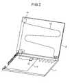
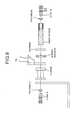
- FIG. 2is a view showing a cooling liquid circulating route of a liquid-cooling for a notebook personal computer according to an embodiment of the present invention
- FIG. 3is views showing a relationship between the cooling liquid circulating route and a plurality of heat generation parts of a notebook personal computer according to an embodiment of the present invention
- FIG. 4is a view showing a route for arranging a cooling liquid circulating tube in a notebook personal computer according to an embodiment of the present invention
- FIG. 5is a view showing a connection structure of a cooling liquid circulating tube and a heat receiving head according to an embodiment of the present invention
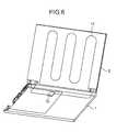
- FIG. 6is a view showing a relationship between a cooling liquid circulating tube and hinges of a liquid crystal display part of a notebook personal computer according to an embodiment of the present invention
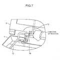
- FIG. 7is a view showing a relationship between hinges of a liquid crystal display part and a tube according to an embodiment of the present invention.
- FIG. 8is a view showing details of the structure shown in FIG. 7;
- FIG. 9is an exploded detailed view of a hinge part of a liquid crystal display part
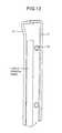
- FIG. 10is a view showing a reserve tank used to replenish a cooling liquid in the tube of an embodiment of the present invention.
- FIG. 11is a detailed structural view of the reserve tank shown in FIG. 10;
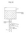
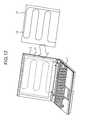
- FIG. 12is a schematic view of a structure in which a heat radiation plate is provided at the rear side of the display part according to an embodiment of the present invention.
- FIG. 13is a cross sectional view of the structure shown in FIG. 12.
- FIG. 14is views showing a detailed structure of the tube filled with cooling liquid.
- FIG. 1is a view showing an entire structure of a liquid-cooling system for a notebook personal computer according to an embodiment of the present invention.
- a notebook personal computeris structured by a body part 1 including a keyboard and a display part 2 including a liquid crystal panel rotatably supported by the body part 1 .
- a mother board (controlling circuit board) 3supported by a housing, etc.
- Various electric/electronic elements, integrated circuits, electronic circuit groups, etc. necessary for operating the personal computerare mounted on the mother board 3 .
- a CPU 4an electronic element, for example, a chip set 5 of IC and the like are also mounted on the mother board 3 , that become heat generating sources during operation of the personal computer. Further, other heat generating sources such as a HDD (Hard Disk Drive) 6 , a. battery part 7 , and a CD-ROM part 8 are housed in the body part 1 .
- the CPU 4is disposed under a W/J (Water Jacket used as a heat receiving head). The heat generated from the CPU 4 is effectively transferred to the heat receiving head.
- W/JWater Jacket used as a heat receiving head
- a heat receiving head (W/J) 10is fixed on the CPU 4 that is the biggest heat source in the body part 1 of the personal computer so that the heat generated from the CPU 4 is collected by cooling liquid circulating in the heat receiving head.
- a tube 12 connected to the heat receiving head 10 and filled with cooling liquidis led between a liquid crystal panel of the display part 2 and a front cover through right and left hinges 14 (see FIG. 7) of the display part 2 .
- the heatis radiated from the front cover or the housing.
- the cooling liquid used in this embodimentmay be pure water or water containing ethylene glycol or the like.
- the circulating means for circulating the cooling liquidis described as a tube, it is not limited only to the tube.
- the heat receiving head 10is provided only for the CPU 4 , which is the biggest heat source disposed in the body part 1 of the personal computer. And, for other heat sources such as the chip set 5 , the HDD 6 , etc., the tube is laid on each of them in a meandering or zigzagging pattern.
- the present inventiondoes not limit the cooling system structure only to that, however.
- a heat receiving headmay also be disposed on the chip set 5 by taking the size and heat radiating value thereof into consideration.
- the tubemay be connected thermally to the chip set 5 , the HDD 6 , etc., for example, with use of a heat transfer member so as to enable the cooling liquid circulating in the tube to absorb the heat.
- the tube connected to the heat receiving head and filled with cooling liquidforms a circulating route disposed in a meandering or zigzagging pattern at the rear side (in the structure shown in FIG. 1) of the liquid crystal panel.
- the tubemay be made not only of silicon or rubber, but also of such metals as Al, Mg, Cu, Ti, SUS, etc. or an alloy of them.
- the tube made of metal or metal alloyis high in heat radiating efficiency, so that it is suitably disposed at the rear side of the liquid crystal panel.
- the metal or metal alloy tubeis not flexible and it is degraded in assembly properties sometimes. In such a case, the metal or metal alloy tube may be combined with a silicon or a rubber flexible tube so as to form a cooling liquid circulating route.
- the tube fixed to the housing of the display part at the rear sideradiates the heat to the outside through the housing or the front cover in contact with the tube.
- the heat radiationis not a local heat radiation by means of heat radiating head as is seen in the prior arts.
- the heatis radiated from the tube laid on all over the housing surface of the display part. Consequently, the cooling liquid circulating tube must be made of a material whose heat radiating efficiency is high, and the housing of the display part at the rear side and the front cover must also be made of a material whose heat radiating efficiency is high.
- the housingmay be made not only of a metal material, but also of a plastic material whose heat radiating efficiency is high.
- the heat generated from the heat generation partis radiated from the rear side of the display part as follows.
- the display partis used in an erected state upon usage of the notebook personal computer.
- the heat radiated from the cooling liquid circulating tubeis transferred or conducted to the housing or the front cover and is transferred to the air outside the housing.
- the display partis in an erected state, a rising air current is resulted along the rear side of the display part, so that the heat transfer is more accelerated.
- the personal computeris operated while the display part is closed. Even in such a case, the heat can be radiated, since the rear side of the display part is in contact with the outside air.
- FIGS. 12 and 13it is possible to place a heat radiation plate for heat diffusion between the display part and the housing or the front cover, to lay the tube in a meandering or zigzagging pattern and to bring the tube in contact with,the heat radiation plate.
- FIG. 12is a view showing a general outline of an embodiment in which a heat radiation plate is provided.
- FIG. 13is a cross sectional view of the display part 2 in that state.
- the heat radiation plate 17 for heat diffusion(corresponding to a metal plate in FIG. 13) is placed inside the housing at the rear side of the liquid crystal panel and the tube is disposed in a meandering or zigzagging pattern so as to come in contact with the heat radiation plate.
- the heat radiation plateBy providing the heat radiation plate, the heat diffusion in the plane direction of the outside of the display part becomes easier. Consequently, the temperature distribution on the housing or the front cover becomes more uniform, thereby the heat radiating efficiency is improved significantly. At this time, in the case where the heat radiation plate is connected thermally to the housing o r the front cover, the heat radiating efficiency is improved more significantly.
- the heat radiating efficiencyis improved by providing the heat radiation plate, the heat radiating amount per unit length of the tube increases, thereby it is possible to reduce the length of the tube coming in contact with the heat radiation plate.
- the tubeis reduced in length, the circulating resistance of the cooling liquid in the tube is also reduced, thereby it is possible to reduce the capacity of the pump for the cooling liquid.
- the personal computercan thus be reduced in both size and power consumption. It goes without saying that the same effect can also be obtained in the case where the heat radiation p late is disposed at t he bottom of the housing and the tube is laid on the heat radiation plate.
- FIG. 2shows that the heat radiation can be effected from the bottom of the body part housing in the case where the tube connected to the heat receiving head (W/J) on the CPU 4 is laid in a meandering or zigzagging pattern at the bottom of the body part 1 .
- the heatis radiated from also the housing of the display part by laying the tube at the rear side of the display part after it passes the bottom of the body part as described above. In this case, the heat generated from the body part is radiated from the bottom of the body part to the desk on which the personal computer is placed, thereby the temperature of the cooling liquid in the tube becomes lower.
- the tubemay be laid only at the bottom according to the heat generation amount.
- a heat receiving headis disposed on the CPU 4 that generates much heat as a matter of course.
- a heat receiving headmay also be disposed on each of a plurality of heat generation parts such as the chip set, etc. so as to collect the heat from them.
- FIG. 3shows an explanatory view of a heat collecting route in those heat generation parts in such a case.
- the arrangement order of the heat generation parts and the cooling liquid flowing directionare decided as follows.
- the CPU 4 , the chip set 5 and the HDD 6are heat sources.
- the power consumption of each of those componentsis as follows; CPU 4 . . . 10 to 30W, chip set 5 . . . 2 to 3W, and HDD 6 . . . 1 to 5W.
- an average power consumption of the HDDis further reduced by save power control at non-access time.
- the allowable operation temperature of each of those devicesis as follows; CPU 4 and chip set 5 . . . 70 to 80° C., HDD 6 . . . 55° C.
- the cooling liquidis pressurized by the pump 11 and it is circulated in the HDD, the chip set, and the CPU sequentially as shown in FIG. 3 ( 2 ) in this embodiment.
- the circulating route decided such wayaims to appropriate the cooling liquid of which temperature is lowered by the heat radiation from the bottom of the body part (see FIG. 2) and the rear side of the display part (see FIG. 1) to cool the HDD, because the allowable operation temperature of the HDD is lower than those of other devices.
- the cooling liquid that has absorbed the heat generated from the HDDrises low in temperature thereof. There is a difference in temperature between the cooling liquid and the heat generation devices.
- the cooling liquidcan absorb the heat generated from the chip set and the CPU.
- the pump 11should be disposed at the downstream of the tube laid at the bottom of the body part and at the rear side of the display part that are located at the upstream of the heat generation part respectively as shown in FIG. 3 ( 1 ) or FIG. 3 ( 2 ). In other words, the pump 11 should be disposed at a place in the cooling liquid circulating route, where the temperature becomes the lowest.
- the cooling liquidmay be circulated in the reverse order of that shown in FIG. 3 ( 2 ), that is, in the order of the CPU, the chip set, and the HDD as shown in FIG. 3 ( 1 ).
- the temperature of the cooling liquidafter having absorbed the heat from the CPU and the chip set, must not exceed the allowable operation temperature of the HDD.
- the heat generated from the CPUcan be radiated via the chip set and the HDD.
- the chip set and the HDDcan release their heat to the cooling liquid when their power consumption is larger, and they absorb the heat from the cooling liquid when their heat generation amounts become lower in such a power saving mode as the standby/sleep, etc.
- FIG. 4shows a heat absorbing route formed by a metal tube, which is led to a palm rest part.
- a heat generation partfor example, the HDD or the like is disposed in a position in the housing, which corresponds to the palm rest. Therefore, when the surface of the housing under the palm rest is heated by the heat generated from the HDD or the like, hands put on the palm rest might feel hot.
- a tubeis laid under the palm rest so as to absorb the heat from the heat generation part located under the palm rest and prevent the temperature on the palm rest from rising.
- the cooling liquidcollects the heat generated from all the heat sources by knowing how much heat is generated from each of them so as to eliminate local high temperature portions from inside the body part so that the temperature of the body part is distributed in uniform, thereby radiating the heat from a wide ranged area of the personal computer.
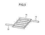
- FIG. 5shows a structure of a heat receiving head and how a tube in which cooling liquid circulates is laid in the heat receiving head in the liquid-cooling art according to an embodiment of the present invention.
- FIG. 5shows the heat receiving head to be placed on such a heat generation part as the CPU and both inlet and outlet pipes of the tube connected to the heat receiving head.
- the heat receiving headforms a zigzag cooling liquid circulating route so as to make the cooling liquid flow all the subject surfaces.
- inlet and output pipes of the heat receiving headare disposed symmetrically with an center of the heat receiving head (inlet and outlet ports connected to the heat receiving head are separated from each other at the longest distance therebetween in FIG. 5 ).
- those outlet and inlet pipe joint portsmay be provided at any positions on the side surfaces of the heat receiving head, which face each other and there is no need that they should be disposed symmetrically with a point therebetween.
- the cooling liquid circulating routeshould be decided so as to circulate the liquid in the tube all over the surface of the heat receiving head.
- FIG. 14shows a structure of the cooling liquid circulating tube according to an embodiment of the present invention.
- cooling liquidis filled in a tube.
- the tubeis made of silicon
- the water content in the cooling liquidmight permeate through the tube, thereby the quantity is reduced or air bubbles might enter the tube while the tube is used for a long time.
- electronic parts used in a personal computerare low in anti-humidity property, thereby the operating life and reliability of those parts might be degraded due to such the permeated water content.
- silicon tubesare excellent in flexibility, so that they are assembled easily and low in price. Therefore, permeation of such the water content is prevented as follows.
- One of such preventive methodsis to cover the surface of the subject tube with a film that does not permeate water content. With this structure, it is possible to prevent the water content in the cooling liquid from permeating. Instead of covering the tube with such a non-permeation film, it is also possible to form a metal film or coat such an oil as grease on the surface of the tube. Another method is to cover the tube to which metal pipes are connected with a cylindrical non-permeation film as shown in FIG. 14 ( 2 ). In this case, although water content of the cooling liquid permeates into a gap between the tube and the non-permeation film, the permeation will be saturated soon, since the area of the gap is very small. The water content permeation can thus be suppressed just to a very small quantity of water. With such structure, it is possible to keep the silicon tube flexibility and to prevent the water content of the cooling liquid from escaping as vapor.
- FIG. 6shows a route of the cooling liquid circulating tube that absorbs the heat from a heat generation part, led to the rear side of the liquid crystal panel of the display part through both right and left hinges (where the display part rotates with respect to the body part of the personal computer) of the display part.
- the inlet pipeis not disposed near the output pipe whose temperature rises due to the heat-absorbed cooling liquid in the structure of this embodiment shown in FIG. 5 .
- the output pipe and the inlet pipeare spaced apart from each other. The cooling liquid in the inlet pipe is therefore not affected by the heat from the outlet pipe while the cooling liquid is fed to the heat receiving head, thereby the thermal conversion is done efficiently in the heat receiving head.
- FIG. 6shows this structure.
- the inlet and outlet ports to the display part of the subject personal computerare disposed together on one side surface of the display part, which is near the heat generation part. This is because such disposition would result an advantage that the total pipe length is reduced.
- the single heat generation part(ex., CPU) is disposed in the top left portion of the body part
- the input pipeis disposed at the left side of a hinge of the display part and the outlet pipe is disposed at the right side of the hinge, and a space must be secured for the outlet pipe in the body part of the personal computer. And, this might arise a problem of downsizing in personal computers.
- the inlet and outlet pipes to the heat receiving headare laid on the same side surface and led to one hinge of the display part.
- the arrangement of the inlet and outlet pipes from the heat receiving headbecomes a characterizing feature coupled organically with the art for cooling a plurality of heat generation parts continuously.
- FIGS. 7, 8 and 9relationship between the hinges of the liquid crystal display part and the cooling liquid circulating tube according to an embodiment of the present invention is shown.
- the liquid crystal display part of the personal computeris provided with a plurality of hinges for rotational movement with respect to the body part of the personal computer and FIG. 7 shows only the left-end hinge.
- these hingesare used as part of the tube route.
- FIG. 7shown is a structure in which the hinge is hollow structure and the tube is passed through a hollow portion of the hinge. According to this tube passing structure, application of a rotational load to the tube accompanied with rotational movement of the display part never occur.
- FIG. 9shows a detailed structure of the hinge shown in FIG. 8 .
- FIGS. 8 and 9show a structure of the hinge to which the tube is fitted.
- Left and right ends of the hingeare structured by joints A and B, and by means provided between those joints A and B, mechanism for rotational movement is structured.
- the joints A and Bdo not rotate when the display part rotates, and a hollow structure is formed so that the cooling liquid filled in the tube flows between the joints A and B.
- ends of the tubesare respectively inserted into the joints A and B from right and left of the hinge, and the tubes are suitably fixed to the joints A and B so as to prevent leakage of the cooling liquid.
- FIGS. 8 and 9when the display part is rotated, the tube is prevented from receiving a rotational load, and the tube is prevented from being rotated together with the display part.
- FIGS. 10 and 11are views showing a configuration and a detailed structure of a reserve tank for replenishing the cooling liquid in the tube according to the embodiment of the present invention.
- the cooling liquid reserve tankis disposed in an upper left corner of the liquid crystal display part and the cooling liquid circulating route of the tube is branched (as shown by an arrow in FIG. 10) to the reserve tank.
- a check valveis provided at a joint between the cooling liquid circulating route and the reserve tank so that replenishment cooling liquid is supplied into the route from the reserve tank while no cooling liquid flows from the route to the reserve tank.
- the reserve tankis provided to cope with cases in which the cooling liquid in the tube leaks and the cooling liquid falls short due to evaporation and the like of the cooling liquid, and it keeps replenishment liquid therein and supplies the liquid into the circulating route at any time.
- a cap of the reserve tank provided at the topis removed to replenish the cooling liquid into the reserve tank while the liquid crystal panel display part is erected.
- the reserve tankis made of a transparent material and a part of the housing corresponding to a reserve tank disposed place is made of a transparent material.
- a bypass path for the reserve tankmay be provided as visible detection means of liquid amount so as to check the liquid level visually in the bypass path.
- the liquid-cooling system of the present inventioncan effectively radiate the heat generated from high heat generation sources such as a CPU, etc. disposed in the body part of a notebook personal computer to the outside, and can radiate the heat generated from heat generation sources such as an HDD and a chip set including the CPU, to the outside, and can achieve a uniform temperature environment all over the surface of the body part.
- high heat generation sourcessuch as a CPU, etc. disposed in the body part of a notebook personal computer to the outside
- heat generation sourcessuch as an HDD and a chip set including the CPU
Landscapes
- Engineering & Computer Science (AREA)
- Theoretical Computer Science (AREA)
- Computer Hardware Design (AREA)
- Physics & Mathematics (AREA)
- Human Computer Interaction (AREA)
- General Engineering & Computer Science (AREA)
- General Physics & Mathematics (AREA)
- Mathematical Physics (AREA)
- Cooling Or The Like Of Electrical Apparatus (AREA)
- Liquid Crystal (AREA)
- Devices For Indicating Variable Information By Combining Individual Elements (AREA)
Abstract
Description
Claims (19)
Priority Applications (1)
| Application Number | Priority Date | Filing Date | Title |
|---|---|---|---|
| US10/307,964US6791834B2 (en) | 2000-12-19 | 2002-12-03 | Liquid cooling system for notebook computer |
Applications Claiming Priority (2)
| Application Number | Priority Date | Filing Date | Title |
|---|---|---|---|
| JP2000-385728 | 2000-12-19 | ||
| JP2000385728AJP3607608B2 (en) | 2000-12-19 | 2000-12-19 | Liquid cooling system for notebook computers |
Related Child Applications (1)
| Application Number | Title | Priority Date | Filing Date |
|---|---|---|---|
| US10/307,964ContinuationUS6791834B2 (en) | 2000-12-19 | 2002-12-03 | Liquid cooling system for notebook computer |
Publications (2)
| Publication Number | Publication Date |
|---|---|
| US20020101716A1 US20020101716A1 (en) | 2002-08-01 |
| US6519148B2true US6519148B2 (en) | 2003-02-11 |
Family
ID=18852944
Family Applications (3)
| Application Number | Title | Priority Date | Filing Date |
|---|---|---|---|
| US09/796,449Expired - LifetimeUS6519147B2 (en) | 2000-12-19 | 2001-03-02 | Notebook computer having a liquid cooling device |
| US09/796,563Expired - LifetimeUS6519148B2 (en) | 2000-12-19 | 2001-03-02 | Liquid cooling system for notebook computer |
| US10/307,964Expired - Fee RelatedUS6791834B2 (en) | 2000-12-19 | 2002-12-03 | Liquid cooling system for notebook computer |
Family Applications Before (1)
| Application Number | Title | Priority Date | Filing Date |
|---|---|---|---|
| US09/796,449Expired - LifetimeUS6519147B2 (en) | 2000-12-19 | 2001-03-02 | Notebook computer having a liquid cooling device |
Family Applications After (1)
| Application Number | Title | Priority Date | Filing Date |
|---|---|---|---|
| US10/307,964Expired - Fee RelatedUS6791834B2 (en) | 2000-12-19 | 2002-12-03 | Liquid cooling system for notebook computer |
Country Status (3)
| Country | Link |
|---|---|
| US (3) | US6519147B2 (en) |
| JP (1) | JP3607608B2 (en) |
| TW (2) | TW550449B (en) |
Cited By (70)
| Publication number | Priority date | Publication date | Assignee | Title |
|---|---|---|---|---|
| US20020075645A1 (en)* | 2000-12-20 | 2002-06-20 | Makoto Kitano | Liquid cooling system and personal computer using thereof |
| US20030128511A1 (en)* | 2000-12-19 | 2003-07-10 | Hitachi, Ltd. | Liquid cooling system for all-in-one computer |
| US20040008485A1 (en)* | 2002-07-15 | 2004-01-15 | Takashi Naganawa | Electronic apparatus |
| US20040027801A1 (en)* | 2000-12-19 | 2004-02-12 | Tsuyoshi Nakagawa | Method of controlling cooling system for a personal computer and personal computer |
| US20040042174A1 (en)* | 2002-08-30 | 2004-03-04 | Kabushiki Kaisha Toshiba | Electronic apparatus |
| US20040070935A1 (en)* | 2002-10-15 | 2004-04-15 | Kabushiki Kaisha Toshiba | Electronic apparatus having a liquid-coolant circulation path and an electric-signal cable |
| US20040070940A1 (en)* | 2002-10-15 | 2004-04-15 | Kabushiki Kaisha Toshiba | Electronic apparatus having a circulation path of liquid coolant to cool a heat-generating component |
| US20040188069A1 (en)* | 2002-08-26 | 2004-09-30 | Kentaro Tomioka | Electronic apparatus having a circulating path of liquid coolant |
| US20040222517A1 (en)* | 2003-05-06 | 2004-11-11 | Robertson Michael F. | Two piece heat sink and device package |
| US20040250989A1 (en)* | 2003-02-11 | 2004-12-16 | Yun-Hyeok Im | Clothespin type heat dissipating apparatus for semiconductor module |
| US20050007739A1 (en)* | 2003-05-26 | 2005-01-13 | Yukihiko Hata | Electronic apparatus having a heat-radiating unit for radiating heat of heat-generating components |
| US20050045310A1 (en)* | 2003-08-29 | 2005-03-03 | Isao Okutsu | Heat pipe, cooling unit having the heat pipe, and electronic apparatus having the cooling unit |
| US20050052833A1 (en)* | 2003-09-04 | 2005-03-10 | Toshiyuki Tanaka | Interlocking mechanism for a display |
| US20050052834A1 (en)* | 2003-09-04 | 2005-03-10 | Toshiyuki Tanaka | Display support mechanism |
| US20050055487A1 (en)* | 2003-09-04 | 2005-03-10 | Toshiyuki Tanaka | Rotating docking station |
| US20050068732A1 (en)* | 2003-09-30 | 2005-03-31 | Hiroyuki Tsuji | Electronic apparatus with air cooling unit |
| US20050077031A1 (en)* | 2003-10-09 | 2005-04-14 | Yoshimitsu Inoue | Cooling system |
| US20050078450A1 (en)* | 2001-09-07 | 2005-04-14 | Shigeo Ohashi | Electronic apparatus |
| US20050105258A1 (en)* | 2003-11-18 | 2005-05-19 | Toshiyuki Tanaka | Apparatus for connecting a display to a body case of an electronic device |
| US20050104847A1 (en)* | 2003-11-18 | 2005-05-19 | Toshiyuki Tanaka | Multi-functional electronic device with a continuously accessible pointing device |
| US20050105263A1 (en)* | 2003-11-18 | 2005-05-19 | Toshiyuki Tanaka | Tablet interlocking mechanism |
| US20050105252A1 (en)* | 2003-11-18 | 2005-05-19 | Toshiyuki Tanaka | Mechanism for adjusting a display |
| US20050105273A1 (en)* | 2003-11-18 | 2005-05-19 | Toshiyuki Tanaka | Cooling apparatus for electronic apparatus |
| US20050117307A1 (en)* | 2003-11-28 | 2005-06-02 | Makoto Tanaka | Electronic apparatus |
| US20050155755A1 (en)* | 2003-12-25 | 2005-07-21 | Matsushita Electric Industrial Co., Ltd. | Liquid cooling device and electronic equipment provided with the same |
| US20050164624A1 (en)* | 2003-12-26 | 2005-07-28 | Kenichi Hisamatsu | Electronic apparatus |
| US20050206615A1 (en)* | 2004-03-22 | 2005-09-22 | Mitsuyoshi Tanimoto | Display support mechanism for an electronic apparatus |
| US20050217828A1 (en)* | 2004-04-02 | 2005-10-06 | Kentaro Tomioka | Pump, cooler, and electronic device |
| US20050241312A1 (en)* | 2004-04-28 | 2005-11-03 | Yukihiko Hata | Pump, electronic apparatus, and cooling system |
| US20050244292A1 (en)* | 2004-04-28 | 2005-11-03 | Kentaro Tomioka | Pump, cooler, and electronic device |
| US20050244291A1 (en)* | 2004-04-28 | 2005-11-03 | Kentaro Tomioka | Pump and electronic apparatus having this pump |
| US20050241809A1 (en)* | 2004-04-28 | 2005-11-03 | Kentaro Tomioka | Pump, cooling system, and electronic apparatus |
| US20050243510A1 (en)* | 2004-04-28 | 2005-11-03 | Kentaro Tomioka | Electronic apparatus with liquid cooling device |
| US20050243518A1 (en)* | 2004-04-28 | 2005-11-03 | Yukihiko Hata | Heat-receiving apparatus and electronic equipment |
| US20050265001A1 (en)* | 2004-05-31 | 2005-12-01 | Tomonori Saito | Cooling system and projection-type image display apparatus using the same |
| US20050264996A1 (en)* | 2004-06-01 | 2005-12-01 | Kentaro Tomioka | Pump, cooling unit and electronic apparatus including cooling unit |
| US20060023421A1 (en)* | 2004-07-30 | 2006-02-02 | Yukihiko Hata | Electronic apparatus with cooling device |
| WO2006047910A1 (en)* | 2004-11-08 | 2006-05-11 | Chunfu Liu | A repeatablely bending heat-conducting and heat-dissipating module with a flexible hinge |
| US20070211431A1 (en)* | 2004-06-04 | 2007-09-13 | Cooligy Inc. | Gimballed attachment for multiple heat exchangers |
| US20070227698A1 (en)* | 2006-03-30 | 2007-10-04 | Conway Bruce R | Integrated fluid pump and radiator reservoir |
| US7280357B2 (en) | 2004-04-28 | 2007-10-09 | Kabushiki Kaisha Toshiba | Pump and electronic device having the pump |
| US20070263356A1 (en)* | 2006-05-02 | 2007-11-15 | Raytheon Company | Method and Apparatus for Cooling Electronics with a Coolant at a Subambient Pressure |
| US20070273290A1 (en)* | 2004-11-29 | 2007-11-29 | Ian Ashdown | Integrated Modular Light Unit |
| US20080013278A1 (en)* | 2006-06-30 | 2008-01-17 | Fredric Landry | Reservoir for liquid cooling systems used to provide make-up fluid and trap gas bubbles |
| US20080024978A1 (en)* | 2006-07-25 | 2008-01-31 | Fujitsu Limited | Electronic apparatus |
| US20080024988A1 (en)* | 2006-07-25 | 2008-01-31 | Fujitsu Limited | Liquid cooling unit and heat receiver therefor |
| US20080023178A1 (en)* | 2006-07-25 | 2008-01-31 | Fujitsu Limited | Liquid cooling unit and heat exchanger therefor |
| US20080024987A1 (en)* | 2006-07-25 | 2008-01-31 | Fujitsu Limited | Liquid cooling unit and heat exchanger therefor |
| US20080024980A1 (en)* | 2006-07-25 | 2008-01-31 | Fujitsu Limited | Electronic apparatus including liquid cooling unit |
| US20080229780A1 (en)* | 2007-03-22 | 2008-09-25 | Raytheon Company | System and Method for Separating Components of a Fluid Coolant for Cooling a Structure |
| US20090009968A1 (en)* | 2006-02-28 | 2009-01-08 | Takeshi Hongo | Cooling device and electronic apparatus |
| US20090020266A1 (en)* | 2005-11-30 | 2009-01-22 | Raytheon Company | System and Method of Boiling Heat Transfer Using Self-Induced Coolant Transport and Impingements |
| US20090046423A1 (en)* | 2007-08-07 | 2009-02-19 | James Hom | Internal access mechanism for a server rack |
| US20090107663A1 (en)* | 2007-10-25 | 2009-04-30 | Raytheon Company | System and Method for Cooling Structures Having Both an Active State and an Inactive State |
| US20090218078A1 (en)* | 2008-02-28 | 2009-09-03 | International Business Machines Corporation | Variable flow computer cooling system for a data center and method of operation |
| US20090234705A1 (en)* | 2008-02-28 | 2009-09-17 | International Business Machines Corporation | Variable performance server system and method of operation |
| US7599184B2 (en) | 2006-02-16 | 2009-10-06 | Cooligy Inc. | Liquid cooling loops for server applications |
| US20090279258A1 (en)* | 2008-05-12 | 2009-11-12 | Moore David A | Hinge connector with liquid coolant path |
| WO2009114102A3 (en)* | 2008-03-10 | 2009-12-30 | Cooligy Inc. | Heat removal from an equipment rack by means of heat exchangers mounted to a door |
| US7672125B2 (en) | 2006-07-25 | 2010-03-02 | Fujitsu Limited | Electronic apparatus |
| US20100096993A1 (en)* | 2004-11-29 | 2010-04-22 | Ian Ashdown | Integrated Modular Lighting Unit |
| US7715194B2 (en) | 2006-04-11 | 2010-05-11 | Cooligy Inc. | Methodology of cooling multiple heat sources in a personal computer through the use of multiple fluid-based heat exchanging loops coupled via modular bus-type heat exchangers |
| US7934386B2 (en) | 2008-02-25 | 2011-05-03 | Raytheon Company | System and method for cooling a heat generating structure |
| US8050036B2 (en) | 2006-07-25 | 2011-11-01 | Fujitsu Limited | Liquid cooling unit and heat receiver therefor |
| US8157001B2 (en) | 2006-03-30 | 2012-04-17 | Cooligy Inc. | Integrated liquid to air conduction module |
| US20120171048A1 (en)* | 2010-12-30 | 2012-07-05 | Hon Hai Precision Industry Co., Ltd. | Electronic device with miniature heat dissipating structure |
| US8464781B2 (en) | 2002-11-01 | 2013-06-18 | Cooligy Inc. | Cooling systems incorporating heat exchangers and thermoelectric layers |
| CN106225390A (en)* | 2016-08-31 | 2016-12-14 | 北京瑞尔腾普科技有限公司 | A kind of gas medium high/low temperature heat transfer system |
| CN107333435A (en)* | 2017-06-26 | 2017-11-07 | 中国科学院空间应用工程与技术中心 | It is a kind of based on space liquid cooling cabinet of the aluminum honeycomb panel as base material |
| US11650641B2 (en) | 2021-01-26 | 2023-05-16 | Dell Products L.P. | Information handling system mass balancing thermal reservoirs |
Families Citing this family (51)
| Publication number | Priority date | Publication date | Assignee | Title |
|---|---|---|---|---|
| JP3607608B2 (en)* | 2000-12-19 | 2005-01-05 | 株式会社日立製作所 | Liquid cooling system for notebook computers |
| JP3452060B1 (en) | 2002-05-15 | 2003-09-29 | 松下電器産業株式会社 | Electronic equipment cooling device |
| JP3885679B2 (en)* | 2002-06-28 | 2007-02-21 | 株式会社日立製作所 | Electronics |
| JP4020725B2 (en)* | 2002-07-29 | 2007-12-12 | 富士通株式会社 | Electronic equipment with energy-saving cooling system |
| JP3609809B2 (en)* | 2002-08-30 | 2005-01-12 | 株式会社東芝 | Electronic device and method for cooling electronic device |
| JP2004139186A (en)* | 2002-10-15 | 2004-05-13 | Toshiba Corp | Electronics |
| WO2005061972A1 (en) | 2002-12-06 | 2005-07-07 | Nanocoolers, Inc. | Cooling of electronics by electrically conducting fluids |
| US7124775B2 (en)* | 2003-02-05 | 2006-10-24 | Neng-Chao Chang | Micro pump device with liquid tank |
| JP4126046B2 (en) | 2003-03-12 | 2008-07-30 | 富士通株式会社 | Electronic equipment cooling structure |
| JP2004348649A (en)* | 2003-05-26 | 2004-12-09 | Toshiba Corp | Electronics |
| US6999316B2 (en)* | 2003-09-10 | 2006-02-14 | Qnx Cooling Systems Inc. | Liquid cooling system |
| EP1531384A3 (en)* | 2003-11-14 | 2006-12-06 | LG Electronics Inc. | Cooling apparatus for portable computer |
| US7106590B2 (en)* | 2003-12-03 | 2006-09-12 | International Business Machines Corporation | Cooling system and method employing multiple dedicated coolant conditioning units for cooling multiple electronics subsystems |
| US7013639B2 (en)* | 2003-12-29 | 2006-03-21 | Qnk Cooling Systems Inc. | Heat differential power system |
| US20050160752A1 (en)* | 2004-01-23 | 2005-07-28 | Nanocoolers, Inc. | Apparatus and methodology for cooling of high power density devices by electrically conducting fluids |
| US20050189089A1 (en)* | 2004-02-27 | 2005-09-01 | Nanocoolers Inc. | Fluidic apparatus and method for cooling a non-uniformly heated power device |
| US20050269691A1 (en)* | 2004-06-04 | 2005-12-08 | Cooligy, Inc. | Counter flow micro heat exchanger for optimal performance |
| JP2006229142A (en)* | 2005-02-21 | 2006-08-31 | Toshiba Corp | Cooling device and electronic device having cooling device |
| JP4381998B2 (en) | 2005-02-24 | 2009-12-09 | 株式会社日立製作所 | Liquid cooling system |
| JP2006261457A (en)* | 2005-03-17 | 2006-09-28 | Fujitsu Ltd | Heat receiving body, heat receiving apparatus and electronic device |
| US20070109746A1 (en)* | 2005-11-15 | 2007-05-17 | Klein David A | Liquid cooling of electronic system and method |
| KR100659339B1 (en) | 2005-11-22 | 2006-12-19 | 주식회사 대우일렉트로닉스 | Display system cooling system |
| US8240359B2 (en)* | 2006-04-17 | 2012-08-14 | Gerald Garrett | Liquid storage and cooling computer case |
| US20080017355A1 (en)* | 2006-05-16 | 2008-01-24 | Hardcore Computer, Inc. | Case for a liquid submersion cooled electronic device |
| US7414845B2 (en) | 2006-05-16 | 2008-08-19 | Hardcore Computer, Inc. | Circuit board assembly for a liquid submersion cooled electronic device |
| US7403392B2 (en)* | 2006-05-16 | 2008-07-22 | Hardcore Computer, Inc. | Liquid submersion cooling system |
| US20080266798A1 (en)* | 2007-04-25 | 2008-10-30 | International Business Machines Corporation | System and method for liquid cooling of an electronic system |
| ES2316291B1 (en)* | 2007-07-26 | 2010-01-08 | Jose Fernando Santacreu Oliver | MIXED REFRIGERATOR FOR COMPUTERS AND ELECTRONIC CIRCUITS. |
| JP2008243201A (en)* | 2008-03-17 | 2008-10-09 | Fujitsu Ltd | Electronic equipment cooling structure |
| US20090323276A1 (en)* | 2008-06-25 | 2009-12-31 | Mongia Rajiv K | High performance spreader for lid cooling applications |
| KR20110027766A (en)* | 2008-07-09 | 2011-03-16 | 휴렛-팩커드 디벨롭먼트 컴퍼니, 엘.피. | Dedicated air intake and air outlet for computer chassis chamber |
| JP5169675B2 (en)* | 2008-09-22 | 2013-03-27 | 富士通株式会社 | Cooling unit and electronic equipment |
| CN102137586A (en)* | 2010-12-31 | 2011-07-27 | 鸿富锦精密工业(深圳)有限公司 | Electronic device |
| SG189562A1 (en)* | 2011-10-13 | 2013-05-31 | Tech Armory Pte Ltd | A heat management system |
| US20140262161A1 (en)* | 2013-03-12 | 2014-09-18 | David Lind Weigand | Method and apparatus for dynamically cooling electronic devices |
| JP6331771B2 (en)* | 2014-06-28 | 2018-05-30 | 日本電産株式会社 | Heat module |
| CN104216490B (en)* | 2014-09-10 | 2019-03-12 | 上海交通大学 | A computer chip liquid cooling system |
| CN104699209B (en)* | 2015-04-03 | 2017-11-21 | 陕西理工大学 | Computer spiral heat dissipation structure |
| US20160377356A1 (en)* | 2015-06-25 | 2016-12-29 | Asia Vital Components Co., Ltd. | Flexible and transformable water-cooling device |
| CN106594797A (en)* | 2017-01-24 | 2017-04-26 | 青岛工学院 | Intelligent electronic smoking quitting lighter for assisting in smoking quitting and use method |
| TWI647994B (en)* | 2017-05-15 | 2019-01-11 | 廣達電腦股份有限公司 | Electronic device with heat-dissipation structure |
| CN107704065B (en)* | 2017-12-06 | 2020-07-31 | 国家电网公司 | Cooling device for server |
| CN108509001B (en)* | 2018-04-02 | 2021-01-15 | 联想(北京)有限公司 | Electronic equipment and water-cooling server thereof |
| CN110134214A (en)* | 2019-05-29 | 2019-08-16 | 英业达科技有限公司 | Portable electronic devices |
| CN110418549B (en)* | 2019-06-18 | 2021-01-29 | 华为技术有限公司 | Heat dissipation assembly and electronic equipment |
| CN111443786B (en)* | 2020-02-28 | 2023-04-11 | 华为技术有限公司 | Heat dissipation pivot, cooling system and electronic equipment |
| CN112286323A (en)* | 2020-11-10 | 2021-01-29 | 上海英众信息科技有限公司 | Notebook computer water-cooling heat dissipation device and use method thereof |
| CN113347817B (en)* | 2021-06-11 | 2023-08-08 | Oppo广东移动通信有限公司 | Electronic device casing, manufacturing method thereof, and electronic device |
| WO2023000072A1 (en)* | 2021-07-22 | 2023-01-26 | Huawei Technologies Co., Ltd. | Heat dissipating element and cooling system for notebook computer and method of manufacturing the element |
| JP7175367B1 (en)* | 2021-10-18 | 2022-11-18 | レノボ・シンガポール・プライベート・リミテッド | Electronics |
| CN114415802B (en)* | 2021-11-23 | 2025-02-18 | 西安交通大学 | A notebook cooling system and method using internal and external two-phase cooling cycle coupling |
Citations (4)
| Publication number | Priority date | Publication date | Assignee | Title |
|---|---|---|---|---|
| JPH07142886A (en) | 1993-11-15 | 1995-06-02 | Hitachi Ltd | Electronic device cooling device |
| US5606341A (en)* | 1995-10-02 | 1997-02-25 | Ncr Corporation | Passive CPU cooling and LCD heating for a laptop computer |
| US6226178B1 (en)* | 1999-10-12 | 2001-05-01 | Dell Usa, L.P. | Apparatus for cooling a heat generating component in a computer |
| US6313990B1 (en)* | 2000-05-25 | 2001-11-06 | Kioan Cheon | Cooling apparatus for electronic devices |
Family Cites Families (7)
| Publication number | Priority date | Publication date | Assignee | Title |
|---|---|---|---|---|
| US5649114A (en)* | 1989-05-01 | 1997-07-15 | Credit Verification Corporation | Method and system for selective incentive point-of-sale marketing in response to customer shopping histories |
| CN101398871B (en)* | 1995-02-13 | 2011-05-18 | 英特特拉斯特技术公司 | Systems and methods for secure transaction management and electronic rights protection |
| JP3915139B2 (en)* | 1996-05-30 | 2007-05-16 | トヨタ自動車株式会社 | Fuel cell power generator |
| JP3067740B2 (en)* | 1997-08-20 | 2000-07-24 | 住友電気工業株式会社 | Ceramic filter module |
| US6307746B1 (en)* | 1999-12-06 | 2001-10-23 | Gateway, Inc. | Power adapter having a thermal cooling assembly for a digital information appliance |
| JP3607608B2 (en)* | 2000-12-19 | 2005-01-05 | 株式会社日立製作所 | Liquid cooling system for notebook computers |
| KR100685923B1 (en)* | 2002-03-25 | 2007-02-23 | 엘지.필립스 엘시디 주식회사 | Bonding device and manufacturing method of liquid crystal display device using the same |
- 2000
- 2000-12-19JPJP2000385728Apatent/JP3607608B2/ennot_activeExpired - Fee Related
- 2001
- 2001-03-02USUS09/796,449patent/US6519147B2/ennot_activeExpired - Lifetime
- 2001-03-02USUS09/796,563patent/US6519148B2/ennot_activeExpired - Lifetime
- 2001-03-06TWTW090105193Apatent/TW550449B/ennot_activeIP Right Cessation
- 2001-03-08TWTW090105429Apatent/TW502149B/ennot_activeIP Right Cessation
- 2002
- 2002-12-03USUS10/307,964patent/US6791834B2/ennot_activeExpired - Fee Related
Patent Citations (4)
| Publication number | Priority date | Publication date | Assignee | Title |
|---|---|---|---|---|
| JPH07142886A (en) | 1993-11-15 | 1995-06-02 | Hitachi Ltd | Electronic device cooling device |
| US5606341A (en)* | 1995-10-02 | 1997-02-25 | Ncr Corporation | Passive CPU cooling and LCD heating for a laptop computer |
| US6226178B1 (en)* | 1999-10-12 | 2001-05-01 | Dell Usa, L.P. | Apparatus for cooling a heat generating component in a computer |
| US6313990B1 (en)* | 2000-05-25 | 2001-11-06 | Kioan Cheon | Cooling apparatus for electronic devices |
Cited By (112)
| Publication number | Priority date | Publication date | Assignee | Title |
|---|---|---|---|---|
| US6798655B2 (en)* | 2000-12-19 | 2004-09-28 | Hitachi, Ltd. | Liquid cooling system for all-in-one computer |
| US20030128511A1 (en)* | 2000-12-19 | 2003-07-10 | Hitachi, Ltd. | Liquid cooling system for all-in-one computer |
| US6879485B2 (en)* | 2000-12-19 | 2005-04-12 | Hitachi, Ltd. | Method of controlling cooling system for a personal computer and personal computer |
| US20040027801A1 (en)* | 2000-12-19 | 2004-02-12 | Tsuyoshi Nakagawa | Method of controlling cooling system for a personal computer and personal computer |
| US6987668B2 (en) | 2000-12-20 | 2006-01-17 | Hitachi, Ltd. | Liquid cooling system and personal computer using thereof |
| US6741464B2 (en)* | 2000-12-20 | 2004-05-25 | Hitachi, Ltd. | Liquid cooling system and personal computer using thereof |
| US20020075645A1 (en)* | 2000-12-20 | 2002-06-20 | Makoto Kitano | Liquid cooling system and personal computer using thereof |
| US20040233635A1 (en)* | 2000-12-20 | 2004-11-25 | Makoto Kitano | Liquid cooling system and personal computer using thereof |
| US20050078450A1 (en)* | 2001-09-07 | 2005-04-14 | Shigeo Ohashi | Electronic apparatus |
| US20040008485A1 (en)* | 2002-07-15 | 2004-01-15 | Takashi Naganawa | Electronic apparatus |
| US20040188069A1 (en)* | 2002-08-26 | 2004-09-30 | Kentaro Tomioka | Electronic apparatus having a circulating path of liquid coolant |
| US7142425B2 (en)* | 2002-08-26 | 2006-11-28 | Kabushiki Kaisha Toshiba | Liquid cooling system including a liquid absorption and a leak detection device |
| US20040042174A1 (en)* | 2002-08-30 | 2004-03-04 | Kabushiki Kaisha Toshiba | Electronic apparatus |
| US20060012958A1 (en)* | 2002-08-30 | 2006-01-19 | Kabushiki Kaisha Toshiba | Electronic apparatus |
| US6845011B2 (en)* | 2002-10-15 | 2005-01-18 | Kabushiki Kaisha Toshiba | Electronic apparatus having a circulation path of liquid coolant to cool a heat-generating component |
| US20040070935A1 (en)* | 2002-10-15 | 2004-04-15 | Kabushiki Kaisha Toshiba | Electronic apparatus having a liquid-coolant circulation path and an electric-signal cable |
| US20040070940A1 (en)* | 2002-10-15 | 2004-04-15 | Kabushiki Kaisha Toshiba | Electronic apparatus having a circulation path of liquid coolant to cool a heat-generating component |
| US8464781B2 (en) | 2002-11-01 | 2013-06-18 | Cooligy Inc. | Cooling systems incorporating heat exchangers and thermoelectric layers |
| US20040250989A1 (en)* | 2003-02-11 | 2004-12-16 | Yun-Hyeok Im | Clothespin type heat dissipating apparatus for semiconductor module |
| US6864573B2 (en) | 2003-05-06 | 2005-03-08 | Daimlerchrysler Corporation | Two piece heat sink and device package |
| US20040222517A1 (en)* | 2003-05-06 | 2004-11-11 | Robertson Michael F. | Two piece heat sink and device package |
| US7273089B2 (en) | 2003-05-26 | 2007-09-25 | Kabushiki Kaisha Toshiba | Electronic apparatus having a heat-radiating unit for radiating heat of heat-generating components |
| US20070230120A1 (en)* | 2003-05-26 | 2007-10-04 | Yukihiko Hata | Electronic Apparatus Having a Heat-Radiating Unit for Radiating Heat of Heat-Generating Components |
| US20050007739A1 (en)* | 2003-05-26 | 2005-01-13 | Yukihiko Hata | Electronic apparatus having a heat-radiating unit for radiating heat of heat-generating components |
| US20050045310A1 (en)* | 2003-08-29 | 2005-03-03 | Isao Okutsu | Heat pipe, cooling unit having the heat pipe, and electronic apparatus having the cooling unit |
| US20050052834A1 (en)* | 2003-09-04 | 2005-03-10 | Toshiyuki Tanaka | Display support mechanism |
| US20050052833A1 (en)* | 2003-09-04 | 2005-03-10 | Toshiyuki Tanaka | Interlocking mechanism for a display |
| US7035090B2 (en) | 2003-09-04 | 2006-04-25 | Kabushiki Kaisha Toshiba | Interlocking mechanism for a display |
| US20050055487A1 (en)* | 2003-09-04 | 2005-03-10 | Toshiyuki Tanaka | Rotating docking station |
| US6961234B2 (en) | 2003-09-04 | 2005-11-01 | Kabushiki Kaisha Toshiba | Display support mechanism |
| US7203062B2 (en) | 2003-09-30 | 2007-04-10 | Kabushiki Kaisha Toshiba | Electronic apparatus with air cooling unit |
| US20050068732A1 (en)* | 2003-09-30 | 2005-03-31 | Hiroyuki Tsuji | Electronic apparatus with air cooling unit |
| US20050077031A1 (en)* | 2003-10-09 | 2005-04-14 | Yoshimitsu Inoue | Cooling system |
| US20050105263A1 (en)* | 2003-11-18 | 2005-05-19 | Toshiyuki Tanaka | Tablet interlocking mechanism |
| US7092246B2 (en) | 2003-11-18 | 2006-08-15 | Kabushiki Kaisha Toshiba | Apparatus for connecting a display to a body case of an electronic device |
| US20050105258A1 (en)* | 2003-11-18 | 2005-05-19 | Toshiyuki Tanaka | Apparatus for connecting a display to a body case of an electronic device |
| US7054145B2 (en) | 2003-11-18 | 2006-05-30 | Kabushiki Kaisha Toshiba | Mechanism for adjusting a display |
| US20050104847A1 (en)* | 2003-11-18 | 2005-05-19 | Toshiyuki Tanaka | Multi-functional electronic device with a continuously accessible pointing device |
| US7042711B2 (en) | 2003-11-18 | 2006-05-09 | Kabushiki Kaisha Toshiba | Multi-functional electronic device with a continuously accessible pointing device |
| US6980423B2 (en) | 2003-11-18 | 2005-12-27 | Kabushiki Kaisha Toshiba | Tablet interlocking mechanism |
| US20050105273A1 (en)* | 2003-11-18 | 2005-05-19 | Toshiyuki Tanaka | Cooling apparatus for electronic apparatus |
| US6958910B2 (en) | 2003-11-18 | 2005-10-25 | Kabushiki Kaisha Toshiba | Cooling apparatus for electronic apparatus |
| US20050105252A1 (en)* | 2003-11-18 | 2005-05-19 | Toshiyuki Tanaka | Mechanism for adjusting a display |
| US7170750B2 (en) | 2003-11-28 | 2007-01-30 | Kabushiki Kaisha Toshiba | Electronic apparatus |
| US20050117307A1 (en)* | 2003-11-28 | 2005-06-02 | Makoto Tanaka | Electronic apparatus |
| US20050155755A1 (en)* | 2003-12-25 | 2005-07-21 | Matsushita Electric Industrial Co., Ltd. | Liquid cooling device and electronic equipment provided with the same |
| US20050164624A1 (en)* | 2003-12-26 | 2005-07-28 | Kenichi Hisamatsu | Electronic apparatus |
| US20050206615A1 (en)* | 2004-03-22 | 2005-09-22 | Mitsuyoshi Tanimoto | Display support mechanism for an electronic apparatus |
| US20050217828A1 (en)* | 2004-04-02 | 2005-10-06 | Kentaro Tomioka | Pump, cooler, and electronic device |
| US7215546B2 (en) | 2004-04-28 | 2007-05-08 | Kabushiki Kaisha Toshiba | Pump, electronic apparatus, and cooling system |
| US20050244292A1 (en)* | 2004-04-28 | 2005-11-03 | Kentaro Tomioka | Pump, cooler, and electronic device |
| US7548425B2 (en) | 2004-04-28 | 2009-06-16 | Kabushiki Kaisha Toshiba | Heat-Receiving apparatus and electronic equipment |
| US7301771B2 (en) | 2004-04-28 | 2007-11-27 | Kabushiki Kaisha Toshiba | Heat-receiving apparatus and electronic equipment |
| US20050241312A1 (en)* | 2004-04-28 | 2005-11-03 | Yukihiko Hata | Pump, electronic apparatus, and cooling system |
| US20050243518A1 (en)* | 2004-04-28 | 2005-11-03 | Yukihiko Hata | Heat-receiving apparatus and electronic equipment |
| US20050243510A1 (en)* | 2004-04-28 | 2005-11-03 | Kentaro Tomioka | Electronic apparatus with liquid cooling device |
| US20050241809A1 (en)* | 2004-04-28 | 2005-11-03 | Kentaro Tomioka | Pump, cooling system, and electronic apparatus |
| US7280357B2 (en) | 2004-04-28 | 2007-10-09 | Kabushiki Kaisha Toshiba | Pump and electronic device having the pump |
| US20050244291A1 (en)* | 2004-04-28 | 2005-11-03 | Kentaro Tomioka | Pump and electronic apparatus having this pump |
| US20080259558A1 (en)* | 2004-04-28 | 2008-10-23 | Kabushiki Kaisha Toshiba | Heat-Receiving Apparatus and Electronic Equipment |
| US7275833B2 (en) | 2004-05-31 | 2007-10-02 | Kabushiki Kaisha Toshiba | Cooling system and projection-type image display apparatus using the same |
| US20050265001A1 (en)* | 2004-05-31 | 2005-12-01 | Tomonori Saito | Cooling system and projection-type image display apparatus using the same |
| US20050264996A1 (en)* | 2004-06-01 | 2005-12-01 | Kentaro Tomioka | Pump, cooling unit and electronic apparatus including cooling unit |
| US20070211431A1 (en)* | 2004-06-04 | 2007-09-13 | Cooligy Inc. | Gimballed attachment for multiple heat exchangers |
| US20060023421A1 (en)* | 2004-07-30 | 2006-02-02 | Yukihiko Hata | Electronic apparatus with cooling device |
| WO2006047910A1 (en)* | 2004-11-08 | 2006-05-11 | Chunfu Liu | A repeatablely bending heat-conducting and heat-dissipating module with a flexible hinge |
| US20100096993A1 (en)* | 2004-11-29 | 2010-04-22 | Ian Ashdown | Integrated Modular Lighting Unit |
| US20070273290A1 (en)* | 2004-11-29 | 2007-11-29 | Ian Ashdown | Integrated Modular Light Unit |
| US9383145B2 (en) | 2005-11-30 | 2016-07-05 | Raytheon Company | System and method of boiling heat transfer using self-induced coolant transport and impingements |
| US20090020266A1 (en)* | 2005-11-30 | 2009-01-22 | Raytheon Company | System and Method of Boiling Heat Transfer Using Self-Induced Coolant Transport and Impingements |
| US7599184B2 (en) | 2006-02-16 | 2009-10-06 | Cooligy Inc. | Liquid cooling loops for server applications |
| US20090009968A1 (en)* | 2006-02-28 | 2009-01-08 | Takeshi Hongo | Cooling device and electronic apparatus |
| US8157001B2 (en) | 2006-03-30 | 2012-04-17 | Cooligy Inc. | Integrated liquid to air conduction module |
| US20070227698A1 (en)* | 2006-03-30 | 2007-10-04 | Conway Bruce R | Integrated fluid pump and radiator reservoir |
| US7715194B2 (en) | 2006-04-11 | 2010-05-11 | Cooligy Inc. | Methodology of cooling multiple heat sources in a personal computer through the use of multiple fluid-based heat exchanging loops coupled via modular bus-type heat exchangers |
| US7908874B2 (en)* | 2006-05-02 | 2011-03-22 | Raytheon Company | Method and apparatus for cooling electronics with a coolant at a subambient pressure |
| US20070263356A1 (en)* | 2006-05-02 | 2007-11-15 | Raytheon Company | Method and Apparatus for Cooling Electronics with a Coolant at a Subambient Pressure |
| US20080013278A1 (en)* | 2006-06-30 | 2008-01-17 | Fredric Landry | Reservoir for liquid cooling systems used to provide make-up fluid and trap gas bubbles |
| US20080024978A1 (en)* | 2006-07-25 | 2008-01-31 | Fujitsu Limited | Electronic apparatus |
| US20080024988A1 (en)* | 2006-07-25 | 2008-01-31 | Fujitsu Limited | Liquid cooling unit and heat receiver therefor |
| US8289701B2 (en) | 2006-07-25 | 2012-10-16 | Fujistu Limited | Liquid cooling unit and heat receiver therefor |
| US20080023178A1 (en)* | 2006-07-25 | 2008-01-31 | Fujitsu Limited | Liquid cooling unit and heat exchanger therefor |
| US8050036B2 (en) | 2006-07-25 | 2011-11-01 | Fujitsu Limited | Liquid cooling unit and heat receiver therefor |
| US20080024987A1 (en)* | 2006-07-25 | 2008-01-31 | Fujitsu Limited | Liquid cooling unit and heat exchanger therefor |
| US7652884B2 (en) | 2006-07-25 | 2010-01-26 | Fujitsu Limited | Electronic apparatus including liquid cooling unit |
| US7672125B2 (en) | 2006-07-25 | 2010-03-02 | Fujitsu Limited | Electronic apparatus |
| US7701715B2 (en) | 2006-07-25 | 2010-04-20 | Fujitsu Limited | Electronic apparatus |
| US20080024980A1 (en)* | 2006-07-25 | 2008-01-31 | Fujitsu Limited | Electronic apparatus including liquid cooling unit |
| US7710722B2 (en) | 2006-07-25 | 2010-05-04 | Fujitsu Limited | Liquid cooling unit and heat exchanger therefor |
| US20080229780A1 (en)* | 2007-03-22 | 2008-09-25 | Raytheon Company | System and Method for Separating Components of a Fluid Coolant for Cooling a Structure |
| US8651172B2 (en) | 2007-03-22 | 2014-02-18 | Raytheon Company | System and method for separating components of a fluid coolant for cooling a structure |
| US7746634B2 (en) | 2007-08-07 | 2010-06-29 | Cooligy Inc. | Internal access mechanism for a server rack |
| US20090046423A1 (en)* | 2007-08-07 | 2009-02-19 | James Hom | Internal access mechanism for a server rack |
| US9644869B2 (en)* | 2007-10-25 | 2017-05-09 | Raytheon Company | System and method for cooling structures having both an active state and an inactive state |
| US20090107663A1 (en)* | 2007-10-25 | 2009-04-30 | Raytheon Company | System and Method for Cooling Structures Having Both an Active State and an Inactive State |
| US7934386B2 (en) | 2008-02-25 | 2011-05-03 | Raytheon Company | System and method for cooling a heat generating structure |
| US20090218078A1 (en)* | 2008-02-28 | 2009-09-03 | International Business Machines Corporation | Variable flow computer cooling system for a data center and method of operation |
| US20100241278A1 (en)* | 2008-02-28 | 2010-09-23 | International Business Machines Coporation | Variable flow computer cooling system for a data center and method of operation |
| US8004832B2 (en) | 2008-02-28 | 2011-08-23 | International Business Machines Corporation | Variable flow computer cooling system for a data center and method of operation |
| US7808780B2 (en)* | 2008-02-28 | 2010-10-05 | International Business Machines Corporation | Variable flow computer cooling system for a data center and method of operation |
| US8107234B2 (en) | 2008-02-28 | 2012-01-31 | International Business Machines Corporation | Variable flow computer cooling system for a data center and method of operation |
| US20100246117A1 (en)* | 2008-02-28 | 2010-09-30 | International Business Machines Coporation | Variable flow computer cooling system for a data center and method of operation |
| US20090234705A1 (en)* | 2008-02-28 | 2009-09-17 | International Business Machines Corporation | Variable performance server system and method of operation |
| US7866173B2 (en) | 2008-02-28 | 2011-01-11 | International Business Machines Corporation | Variable performance server system and method of operation |
| US8250877B2 (en) | 2008-03-10 | 2012-08-28 | Cooligy Inc. | Device and methodology for the removal of heat from an equipment rack by means of heat exchangers mounted to a door |
| WO2009114102A3 (en)* | 2008-03-10 | 2009-12-30 | Cooligy Inc. | Heat removal from an equipment rack by means of heat exchangers mounted to a door |
| US7791876B2 (en) | 2008-05-12 | 2010-09-07 | Hewlett-Packard Development Company, L.P. | Hinge connector with liquid coolant path |
| US20090279258A1 (en)* | 2008-05-12 | 2009-11-12 | Moore David A | Hinge connector with liquid coolant path |
| US20120171048A1 (en)* | 2010-12-30 | 2012-07-05 | Hon Hai Precision Industry Co., Ltd. | Electronic device with miniature heat dissipating structure |
| CN106225390A (en)* | 2016-08-31 | 2016-12-14 | 北京瑞尔腾普科技有限公司 | A kind of gas medium high/low temperature heat transfer system |
| CN107333435A (en)* | 2017-06-26 | 2017-11-07 | 中国科学院空间应用工程与技术中心 | It is a kind of based on space liquid cooling cabinet of the aluminum honeycomb panel as base material |
| US11650641B2 (en) | 2021-01-26 | 2023-05-16 | Dell Products L.P. | Information handling system mass balancing thermal reservoirs |
Also Published As
| Publication number | Publication date |
|---|---|
| US6791834B2 (en) | 2004-09-14 |
| JP3607608B2 (en) | 2005-01-05 |
| JP2002182797A (en) | 2002-06-26 |
| US20020101716A1 (en) | 2002-08-01 |
| US6519147B2 (en) | 2003-02-11 |
| TW550449B (en) | 2003-09-01 |
| US20020075643A1 (en) | 2002-06-20 |
| US20030081380A1 (en) | 2003-05-01 |
| TW502149B (en) | 2002-09-11 |
Similar Documents
| Publication | Publication Date | Title |
|---|---|---|
| US6519148B2 (en) | Liquid cooling system for notebook computer | |
| US8289701B2 (en) | Liquid cooling unit and heat receiver therefor | |
| EP1890217B1 (en) | Electronic apparatus with liquid cooling unit and heat exchanger | |
| CN101115373B (en) | Electronic apparatus including liquid cooling unit | |
| US7672125B2 (en) | Electronic apparatus | |
| CN101115375B (en) | Electronic apparatus | |
| KR100899368B1 (en) | Heat receiver for liquid cooling unit, liquid cooling unit and electronic apparatus | |
| TWI382300B (en) | Liquid cooling unit and heat exchanger therefor | |
| JP2003263244A (en) | Information processing equipment and cooling system | |
| JP2004127288A (en) | Cooling module in liquid cooling system of notebook type personal computer |
Legal Events
| Date | Code | Title | Description |
|---|---|---|---|
| AS | Assignment | Owner name:HITACHI, LTD., JAPAN Free format text:ASSIGNMENT OF ASSIGNORS INTEREST;ASSIGNORS:NAKAGAWA, TSUYOSHI;NEHO, YASUSHI;MATSUOKA, TATSUHIKO;AND OTHERS;REEL/FRAME:013344/0758;SIGNING DATES FROM 20010410 TO 20010411 | |
| STCF | Information on status: patent grant | Free format text:PATENTED CASE | |
| FEPP | Fee payment procedure | Free format text:PAYOR NUMBER ASSIGNED (ORIGINAL EVENT CODE: ASPN); ENTITY STATUS OF PATENT OWNER: LARGE ENTITY | |
| FPAY | Fee payment | Year of fee payment:4 | |
| FEPP | Fee payment procedure | Free format text:PAYOR NUMBER ASSIGNED (ORIGINAL EVENT CODE: ASPN); ENTITY STATUS OF PATENT OWNER: LARGE ENTITY Free format text:PAYER NUMBER DE-ASSIGNED (ORIGINAL EVENT CODE: RMPN); ENTITY STATUS OF PATENT OWNER: LARGE ENTITY | |
| FPAY | Fee payment | Year of fee payment:8 | |
| AS | Assignment | Owner name:HITACHI CONSUMER ELECTRONICS CO., LTD., JAPAN Free format text:ASSIGNMENT OF ASSIGNORS INTEREST;ASSIGNOR:HITACHI, LTD.;REEL/FRAME:030648/0217 Effective date:20130607 | |
| FPAY | Fee payment | Year of fee payment:12 | |
| AS | Assignment | Owner name:HITACHI MAXELL, LTD., JAPAN Free format text:ASSIGNMENT OF ASSIGNORS INTEREST;ASSIGNORS:HITACHI CONSUMER ELECTRONICS CO., LTD.;HITACHI CONSUMER ELECTRONICS CO, LTD.;REEL/FRAME:033694/0745 Effective date:20140826 | |
| AS | Assignment | Owner name:MAXELL, LTD., JAPAN Free format text:ASSIGNMENT OF ASSIGNORS INTEREST;ASSIGNOR:HITACHI MAXELL, LTD.;REEL/FRAME:045142/0208 Effective date:20171001 |