US6518691B1 - Area type light emitting device and manufacturing method thereof - Google Patents
Area type light emitting device and manufacturing method thereofDownload PDFInfo
- Publication number
- US6518691B1 US6518691B1US09/575,093US57509300AUS6518691B1US 6518691 B1US6518691 B1US 6518691B1US 57509300 AUS57509300 AUS 57509300AUS 6518691 B1US6518691 B1US 6518691B1
- Authority
- US
- United States
- Prior art keywords
- light guide
- guide component
- component
- reflection
- transparent light
- Prior art date
- Legal status (The legal status is an assumption and is not a legal conclusion. Google has not performed a legal analysis and makes no representation as to the accuracy of the status listed.)
- Expired - Fee Related
Links
Images


Classifications
- G—PHYSICS
- G02—OPTICS
- G02F—OPTICAL DEVICES OR ARRANGEMENTS FOR THE CONTROL OF LIGHT BY MODIFICATION OF THE OPTICAL PROPERTIES OF THE MEDIA OF THE ELEMENTS INVOLVED THEREIN; NON-LINEAR OPTICS; FREQUENCY-CHANGING OF LIGHT; OPTICAL LOGIC ELEMENTS; OPTICAL ANALOGUE/DIGITAL CONVERTERS
- G02F1/00—Devices or arrangements for the control of the intensity, colour, phase, polarisation or direction of light arriving from an independent light source, e.g. switching, gating or modulating; Non-linear optics
- G02F1/01—Devices or arrangements for the control of the intensity, colour, phase, polarisation or direction of light arriving from an independent light source, e.g. switching, gating or modulating; Non-linear optics for the control of the intensity, phase, polarisation or colour
- G02F1/13—Devices or arrangements for the control of the intensity, colour, phase, polarisation or direction of light arriving from an independent light source, e.g. switching, gating or modulating; Non-linear optics for the control of the intensity, phase, polarisation or colour based on liquid crystals, e.g. single liquid crystal display cells
- G02F1/133—Constructional arrangements; Operation of liquid crystal cells; Circuit arrangements
- G02F1/1333—Constructional arrangements; Manufacturing methods
- G02F1/1335—Structural association of cells with optical devices, e.g. polarisers or reflectors
- G—PHYSICS
- G02—OPTICS
- G02B—OPTICAL ELEMENTS, SYSTEMS OR APPARATUS
- G02B6/00—Light guides; Structural details of arrangements comprising light guides and other optical elements, e.g. couplings
- G02B6/0001—Light guides; Structural details of arrangements comprising light guides and other optical elements, e.g. couplings specially adapted for lighting devices or systems
- G02B6/0011—Light guides; Structural details of arrangements comprising light guides and other optical elements, e.g. couplings specially adapted for lighting devices or systems the light guides being planar or of plate-like form
- G02B6/0033—Means for improving the coupling-out of light from the light guide
- G02B6/0035—Means for improving the coupling-out of light from the light guide provided on the surface of the light guide or in the bulk of it
- G02B6/0036—2-D arrangement of prisms, protrusions, indentations or roughened surfaces
- G—PHYSICS
- G02—OPTICS
- G02B—OPTICAL ELEMENTS, SYSTEMS OR APPARATUS
- G02B6/00—Light guides; Structural details of arrangements comprising light guides and other optical elements, e.g. couplings
- G02B6/0001—Light guides; Structural details of arrangements comprising light guides and other optical elements, e.g. couplings specially adapted for lighting devices or systems
- G02B6/0011—Light guides; Structural details of arrangements comprising light guides and other optical elements, e.g. couplings specially adapted for lighting devices or systems the light guides being planar or of plate-like form
- G02B6/0033—Means for improving the coupling-out of light from the light guide
- G02B6/0035—Means for improving the coupling-out of light from the light guide provided on the surface of the light guide or in the bulk of it
- G02B6/0038—Linear indentations or grooves, e.g. arc-shaped grooves or meandering grooves, extending over the full length or width of the light guide
- G—PHYSICS
- G02—OPTICS
- G02B—OPTICAL ELEMENTS, SYSTEMS OR APPARATUS
- G02B6/00—Light guides; Structural details of arrangements comprising light guides and other optical elements, e.g. couplings
- G02B6/0001—Light guides; Structural details of arrangements comprising light guides and other optical elements, e.g. couplings specially adapted for lighting devices or systems
- G02B6/0011—Light guides; Structural details of arrangements comprising light guides and other optical elements, e.g. couplings specially adapted for lighting devices or systems the light guides being planar or of plate-like form
- G02B6/0065—Manufacturing aspects; Material aspects
- G—PHYSICS
- G02—OPTICS
- G02B—OPTICAL ELEMENTS, SYSTEMS OR APPARATUS
- G02B6/00—Light guides; Structural details of arrangements comprising light guides and other optical elements, e.g. couplings
- G02B6/0001—Light guides; Structural details of arrangements comprising light guides and other optical elements, e.g. couplings specially adapted for lighting devices or systems
- G02B6/0011—Light guides; Structural details of arrangements comprising light guides and other optical elements, e.g. couplings specially adapted for lighting devices or systems the light guides being planar or of plate-like form
- G02B6/0033—Means for improving the coupling-out of light from the light guide
- G02B6/005—Means for improving the coupling-out of light from the light guide provided by one optical element, or plurality thereof, placed on the light output side of the light guide
- G02B6/0051—Diffusing sheet or layer
- G—PHYSICS
- G02—OPTICS
- G02B—OPTICAL ELEMENTS, SYSTEMS OR APPARATUS
- G02B6/00—Light guides; Structural details of arrangements comprising light guides and other optical elements, e.g. couplings
- G02B6/0001—Light guides; Structural details of arrangements comprising light guides and other optical elements, e.g. couplings specially adapted for lighting devices or systems
- G02B6/0011—Light guides; Structural details of arrangements comprising light guides and other optical elements, e.g. couplings specially adapted for lighting devices or systems the light guides being planar or of plate-like form
- G02B6/0033—Means for improving the coupling-out of light from the light guide
- G02B6/005—Means for improving the coupling-out of light from the light guide provided by one optical element, or plurality thereof, placed on the light output side of the light guide
- G02B6/0055—Reflecting element, sheet or layer
- G—PHYSICS
- G02—OPTICS
- G02B—OPTICAL ELEMENTS, SYSTEMS OR APPARATUS
- G02B6/00—Light guides; Structural details of arrangements comprising light guides and other optical elements, e.g. couplings
- G02B6/0001—Light guides; Structural details of arrangements comprising light guides and other optical elements, e.g. couplings specially adapted for lighting devices or systems
- G02B6/0011—Light guides; Structural details of arrangements comprising light guides and other optical elements, e.g. couplings specially adapted for lighting devices or systems the light guides being planar or of plate-like form
- G02B6/0033—Means for improving the coupling-out of light from the light guide
- G02B6/0058—Means for improving the coupling-out of light from the light guide varying in density, size, shape or depth along the light guide
- G02B6/0061—Means for improving the coupling-out of light from the light guide varying in density, size, shape or depth along the light guide to provide homogeneous light output intensity
Definitions
- the present inventionrelates to an area type light emitting device and a manufacturing method thereof, which are used for a transmission type display unit that does not emit light for itself such as a liquid crystal display (LCD) unit.
- a transmission type display unitthat does not emit light for itself
- LCDliquid crystal display
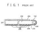
- FIG. 1is a sectional view of a conventional area type light emitting device.
- the conventional area type light emitting deviceconsists of a light source 100 , a reflector 102 , and a light guide unit 201 .
- the light guide unit 201consists of a light guide component 202 , a diffusion component 204 , a reflection component 206 , a reflection pattern 208 , and an adhesive 210 .
- the reflection pattern 208which makes emitted light from the light source 100 reflect irregularly or regularly, is formed by transferring a pattern used a screen printing on the reverse side (the side existing the reflection component 206 ) of the light guide component 202 .
- the reflection pattern 208is formed on the light guide component 202 by that the reflection pattern 208 is also formed in a molding die forming the light guide component 202 .
- the reflection component 206is fixed to the light guide component 202 by using the adhesive 210 such as a both sides adhesive tape on the edge sides of the reflection component 206 . Consequently, displacement, bending, and deformation of the reflection component 206 occur for the light guide component 202 under a high temperature environment. Therefore, this is not enough for keeping good quality.
- Japanese Patent Application Laid-Open No. HEI 4-191704discloses an area type light emitting device and a manufacturing method thereof
- a transparent pattern adhesive layerwhich is a reflection pattern whose reflection area becomes larger corresponding to farther the distance from a light source, is provided between a light guide component and a reflection component.
- this transparent pattern adhesive layerworks as the reflection pattern of the reverse side of the light guide component and also works as a means for fixing the reflection component to the light guide component. Therefore, this structure is effective for reducing a cost and for decreasing the non-uniformity of the brightness of the area type light emitting device.
- this area type light emitting deviceuses an adhesive means as a fixing means for fixing the reflection component to the light guide component, therefore, the non-uniformity of the brightness occurs depending on the condition of environment, that is, the problem at the conventional method is not solved completely.
- This conventional methoduses an adhesive whose main material is a resin as the transparent pattern adhesive layer. Consequently, for example, at a high temperature environment, this adhesive is softened and the reflection component is displaced or deformed by its own weight or its structure for the light guide component, as a result, a non-uniform gap occurs between the light guide component and the reflection component.
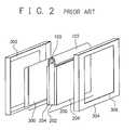
- FIG. 2is a perspective view of a disassembled LCD unit used an area type light emitting device.
- the LCD unitprovides a LCD panel unit 300 , a front bezel 302 , an area type light emitting device 200 , and a frame 304 , and the frame 304 has an opening part 306 .
- the frame 304 holding the area type light emitting device 200is formed as a rectangular frame. Therefore, the reflection component 206 is displaced or deformed in the opening part 306 of the frame 304 by a high temperature environment and this causes a problem that hazy nonuniformity or an extraordinary bright part being a bright spot state occurs on the LCD unit.
- this area type light emitting devicethere is a process to fix the reflection component 206 to the light guide component 202 by using an adhesive, or a process to form a reflection pattern by printing in addition to a process to fix the reflection component 206 to the light guide component 202 . Therefore, the manufacturing cost will not be reduced largely.
- a reflection componentis disposed on the reverse face of a transparent light guide component, and also a light source is disposed at the side of said transparent light guide component, makes light emit from the surface of said transparent light guide component by that emitted light from said light source is inputted to said transparent light guide component and said inputted light is reflected on said reflection component and said reflected light is passed through said surface of said transparent light guide component, at the time when a reflection pattern, which makes said emitted light from said light source reflect to said surface of said transparent light guide component, is formed on said reverse face of said transparent light guide component, said reverse face of said transparent light guide component and said reflection component are fixed by welding in a state that said reflection pattern is formed between said reverse face of said transparent light guide component and said reflection component. Therefore, said reflection component can be firmly fixed to said transparent light guide component, and the manufacturing cost can be reduced.
- a reflection componentis disposed on the reverse face of a transparent light guide component, and also a light source is disposed at the side of said transparent light guide component, makes light emit from the surface of said transparent light guide component by that emitted light from said light source is inputted to said transparent light guide component and said inputted light is reflected on said reflection component and said reflected light is passed through said surface of said transparent light guide component, at the same time when a reflection pattern, which makes said emitted light from said light source reflect to said surface of said transparent light guide component, is formed on said reverse face of said transparent light guide component, said reverse face of said transparent light guide component and said reflection component are fixed by welding in a state that said reflection pattern is formed between said reverse face of said transparent light guide component and said reflection component.
- a reflection componentis disposed on the reverse face of a transparent light guide component, and also a light source is disposed at the side of said transparent light guide component, makes light emit from the surface of said transparent light guide component by that emitted light from said light source is inputted to said transparent light guide component and said inputted light is reflected on said reflection component and said reflected light is passed through said surface of said transparent light guide component, at the same time when said transparent light guide component is molded, a reflection pattern, which makes said emitted light from said light source reflect to said surface of said transparent light guide component, is formed on said reverse face of said transparent light guide component, and said reverse face of said transparent light guide component and said reflection component are fixed by welding in a state that said reflection pattern contacts with said reflection component. Therefore, a process that said reflection pattern is formed on said reverse face of said transparent light guide component is not required, consequently the manufacturing cost can be reduced, and said reflection component can be firmly fixed to
- FIG. 1is a sectional view of a conventional area type light emitting device
- FIG. 2is a perspective view of a disassembled LCD unit used an area type light emitting device
- FIG. 3is a sectional view of a first embodiment of an area type light emitting device of the present invention.
- FIG. 4is a sectional view of a second embodiment of an area type light emitting device of the present invention.
- FIG. 3is a sectional view of a first embodiment of an area type light emitting device of the present invention.
- the area type light emitting device of the first embodiment of the present inventionconsists of a pole type light source 10 , a reflector 12 which reflects emitted light from the pole type light source 10 effectively, and a light guide unit 20 which makes light diffuse uniformly.
- the light guide unit 20consists of a transparent light guide component 22 , a diffusion component 24 , a reflection component 26 , and a reflection pattern 28 .
- the transparent light guide component 22is made of a transparent resin material.
- the reflection pattern 28being a dot type, or a line type, or a random satin finish, which makes the emitted light from the light source 10 that is disposed at the side of the transparent light guide component 22 reflect irregularly or regularly, is formed on the reverse face of the transparent light guide component 22 .
- This reflection pattern 28works so that the area type light emitting device has an uniformity and not uneven characteristic by that the reflection pattern 28 reflects and diffuses the light inputted to the transparent light guide component 22 from the light source 10 to the outputting side.
- the reflection component 26is disposed at a state that the pattern side of the reflection pattern 28 is jointed with the reflection component 26 .
- the diffusion component 24is disposed on the surface of the transparent light guide component 22 , that is, on the outputting side of reflected light from the reflection component 26 .
- the reflection component 26 and the diffusion component 24are a sheet type, or a film type, or a plate type resin material, and further the reflection component 26 has a glossy face, or a satin finish face, or a wrinkle face, or a foam surface of a white resin material or a metal film. And the diffusion component 24 works as a function diffusing light or collecting light depending on its object.
- the transparent light guide component 22 and the reflection component 26are welded by applying an ultrasonic wave or heat from the outside of the reflection component 26 , at the same time when the reflection pattern 28 is formed on the reverse face of the transparent light guide component 22 , by pressing a jig having the pattern of the reflection pattern 28 from the outside.
- the process that the transparent light guide component 22 and the reflection component 26 are jointed and the process the reflection pattern 28 is formedcan be unified and performed at the same time. Consequently, the reflection component 26 is fixed to the transparent light guide component 22 on the wide area. And at the jointing surface of the transparent light guide component 22 with the reflection component 26 , air layers between the transparent light guide component 22 and the reflection component 26 exist at the parts where the reflection pattern 28 for reflecting regularly or irregularly the emitted light is not formed. With these air layers, the emitted light reflects effectively.
- the manufacturing cost of the area type light emitting devicecan be reduced. Moreover, the bad effects caused by the displacement and peeling of the reflection component 26 for the transparent light guide component 22 can be avoided. Further, the inputted light to the transparent light guide component 22 from the light source 10 is not leaked from the transparent light guide component 22 , and the inputted light can be used effectively.
- the reflection component 26is fixed to the transparent light guide component 22 by welding from the outside of the reflection component 26 at the same time when the reflection pattern 28 is formed on the reverse face of the transparent light guide component 22 .
- the tightness and fixation of the reflection component 26 to the transparent light guide component 22 at the reflection pattern 28 (welding part)are improved largely.
- the ultrasonic wave weldingis a method in which the vibration generated by an ultrasonic wave is applied to a part by using a welding tool called horn, and the friction occurs at a part between the transparent light guide component 22 and the reflection component 26 , and the welding is performed by the heat generated by this friction.
- the heat weldingis a method in which the heat is generated by that a conductive or magnetic material and the transparent light guide component 22 and the reflection component 26 are placed in a high frequency magnetic field.
- the jig formed the pattern of the reflection pattern 28is pressed from the outside of the reflection component 26 at the same time when the transparent light guide component 22 and the reflection component 26 are welded, and after this, cooling is applied and the transparent light guide component 22 and the reflection component 26 are fixed.
- the other heat welding methodsthere are methods such as a heat plate welding, a heat seal welding, and an impulse seal welding. These methods use a heat element having a large electric resistance, and make this heat element contact and press directly the welding part. With this, the transparent light guide component 22 and the reflection component 26 are softened and welded, and at this state the transparent light guide component 22 and the reflection component 26 are pressed and jointed. At the manufacturing method of the first embodiment of the area type light emitting device of the present invention, the welding process is adopted, therefore, a strong joint between the transparent light guide component 22 and the reflection component 26 can be obtained.
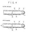
- FIG. 4is a sectional view of the second embodiment of the area type light emitting device of the present invention.
- the area type light emitting device of the second embodiment of the present inventionconsists of a pole type light source 10 , a reflector 12 which reflects emitted light from the pole type light source 10 effectively, and a light guide unit 30 which makes light diffuse uniformly.
- the light guide unit 30consists of a transparent light guide component 32 , a diffusion component 24 , a reflection component 36 , and a reflection pattern 34 .
- the reflection component 26is fixed to the transparent light guide component 22 by welding, at the same time when the reflection pattern 28 is formed on the transparent light guide component 22 .
- the reflection pattern 34is formed on the transparent light guide component 22 beforehand, and the reflection component 36 is fixed to the transparent light guide component 32 having the reflection pattern 34 by welding.
- the reflection pattern 34is formed on the reverse face of the transparent light guide component 32 beforehand. That is, the reflection pattern 34 is formed on the transparent light guide component 32 , at the same time when the transparent light guide component 32 is formed by molding. And the pattern of the reflection pattern 34 is a dot type, or a line type, or a satin finish, and has a slight height from a plane where the pattern does not exist.
- the reflection component 36is disposed so that the reflection component 36 contacts with the reflection pattern 34 , and this contacted part is softened and welded by the ultrasonic wave welding or the heat welding.
- the weldingis used to fix the reflection component 36 to the transparent light guide component 32 as a fixing means, and the reflection component 36 is fixed to the reflection pattern 34 which is formed at the same time when the transparent light guide component 32 is formed. Therefore, as the same as the first embodiment, at the second embodiment, the manufacturing cost is reduced, and bad effects such as the displacement and peeling of the reflection component 36 for the transparent light guide component 32 can be avoided. Further, the light inputted to the transparent light guide component 32 from the light source 10 does not leak at the transparent light guide component 32 and can be used effectively. Moreover, the reflection pattern 34 is formed on the transparent light guide component 32 beforehand, therefore a tool using for welding can be simplified. Therefore, the manufacturing cost at the welding is further reduced.
- an area type light emitting devicein which a reflection component is disposed on the reverse face of a transparent light guide component, and also a light source is disposed at the side of the transparent light guide component, makes light emit from the surface of the transparent light guide component by that emitted light from the light source is inputted to the transparent light guide component and the inputted light is reflected on the reflection component and the reflected light is passed through the surface of the transparent light guide component, at the time when a reflection pattern, which makes the emitted light from the light source reflect to the surface of the transparent light guide component, is formed on the reverse face of the transparent light guide component, the reverse face of the transparent light guide component and the reflection component are fixed by welding in a state that the reflection pattern is formed between the reverse face of the transparent light guide component and the reflection component. Therefore, the reflection component can be firmly fixed to the transparent light guide component, and the manufacturing cost can be reduced.
- a reflection componentis disposed on the reverse face of a transparent light guide component, and also a light source is disposed at the side of the transparent light guide component, makes light emit from the surface of the transparent light guide component by that emitted light from the light source is inputted to the transparent light guide component and the inputted light is reflected on the reflection component and the reflected light is passed through the surface of the transparent light guide component, at the same time when a reflection pattern, which makes the emitted light from the light source reflect to the surface of the transparent light guide component, is formed on the reverse face of the transparent light guide component, the reverse face of the transparent light guide component and the reflection component are fixed by welding in a state that the reflection pattern is formed between the reverse face of the transparent light guide component and the reflection component.
- a process that the reflection component is jointed with the transparent light guide component and a process that the reflection pattern is formed on the transparent light guide componentcan be unified, consequently, the manufacturing cost can be reduced and the reflection component can be firmly fixed to the transparent light guide component.
- a reflection componentis disposed on the reverse face of a transparent light guide component, and also a light source is disposed at the side of the transparent light guide component, makes light emit from the surface of the transparent light guide component by that emitted light from the light source is inputted to the transparent light guide component and the inputted light is reflected on the reflection component and the reflected light is passed through the surface of the transparent light guide component, at the same time when the transparent light guide component is molded, a reflection pattern, which makes the emitted light from the light source reflect to the surface of the transparent light guide component, is formed on the reverse face of the transparent light guide component, and the reverse face of the transparent light guide component and the reflection component are fixed by welding in a state that the reflection pattern contacts with the reflection component. Therefore, a process that the reflection pattern is formed on the reverse face of the transparent light guide component is not required, consequently the manufacturing cost can be reduced, and the reflection component can be firmly fixed to the transparent light guide component
Landscapes
- Physics & Mathematics (AREA)
- General Physics & Mathematics (AREA)
- Optics & Photonics (AREA)
- Engineering & Computer Science (AREA)
- Manufacturing & Machinery (AREA)
- Nonlinear Science (AREA)
- Mathematical Physics (AREA)
- Chemical & Material Sciences (AREA)
- Crystallography & Structural Chemistry (AREA)
- Planar Illumination Modules (AREA)
- Light Guides In General And Applications Therefor (AREA)
- Liquid Crystal (AREA)
Abstract
Description
Claims (3)
Applications Claiming Priority (2)
| Application Number | Priority Date | Filing Date | Title |
|---|---|---|---|
| JP11-153058 | 1999-05-31 | ||
| JP11153058AJP2000348516A (en) | 1999-05-31 | 1999-05-31 | Sheet-form light emitting device and manufacture thereof |
Publications (1)
| Publication Number | Publication Date |
|---|---|
| US6518691B1true US6518691B1 (en) | 2003-02-11 |
Family
ID=15554070
Family Applications (1)
| Application Number | Title | Priority Date | Filing Date |
|---|---|---|---|
| US09/575,093Expired - Fee RelatedUS6518691B1 (en) | 1999-05-31 | 2000-05-19 | Area type light emitting device and manufacturing method thereof |
Country Status (4)
| Country | Link |
|---|---|
| US (1) | US6518691B1 (en) |
| JP (1) | JP2000348516A (en) |
| KR (1) | KR100404352B1 (en) |
| TW (1) | TW461975B (en) |
Cited By (34)
| Publication number | Priority date | Publication date | Assignee | Title |
|---|---|---|---|---|
| US20040119668A1 (en)* | 2002-12-05 | 2004-06-24 | Kenji Homma | Light emitting device and apparatus using the same |
| US20050215166A1 (en)* | 2001-09-27 | 2005-09-29 | Lothar Hitzschke | Discharge lamp with stabilized discharge vessel plate |
| US20090243824A1 (en)* | 2008-03-31 | 2009-10-01 | Magna Mirrors Of America, Inc. | Interior rearview mirror system |
| WO2010097207A1 (en)* | 2009-02-27 | 2010-09-02 | Prettl, Rolf | Optical diffuser, light box, injection mould and use of an injection mould |
| US20110045172A1 (en)* | 1994-05-05 | 2011-02-24 | Donnelly Corporation | Method of forming a mirrored bent cut glass shape for vehicular exterior rearview mirror assembly |
| US20110084198A1 (en)* | 2002-09-20 | 2011-04-14 | Donnelly Corporation | Interior rearview mirror information display system for a vehicle |
| US20110096387A1 (en)* | 2002-09-20 | 2011-04-28 | Donnelly Corporation | Reflective mirror assembly |
| US20110128137A1 (en)* | 1994-05-05 | 2011-06-02 | Donnelly Corporation | Vehicular blind spot indicator mirror |
| US20110147570A1 (en)* | 2002-05-03 | 2011-06-23 | Donnelly Corporation | Vehicle rearview mirror system |
| US20110164135A1 (en)* | 1998-01-07 | 2011-07-07 | Donnelly Corporation | Interior rearview mirror system |
| US20110166779A1 (en)* | 1999-11-24 | 2011-07-07 | Donnelly Corporation | Interior rearview mirror system |
| US20110169956A1 (en)* | 1997-08-25 | 2011-07-14 | Donnelly Corporation | Interior rearview mirror system for a vehicle |
| EP2352045A1 (en)* | 2010-01-29 | 2011-08-03 | Zumtobel Lighting GmbH | Assembly for influencing light with a light conducting element and a reflector element |
| US8063753B2 (en) | 1997-08-25 | 2011-11-22 | Donnelly Corporation | Interior rearview mirror system |
| US8083386B2 (en) | 2001-01-23 | 2011-12-27 | Donnelly Corporation | Interior rearview mirror assembly with display device |
| US8095260B1 (en) | 2003-10-14 | 2012-01-10 | Donnelly Corporation | Vehicle information display |
| US8095310B2 (en) | 2000-03-02 | 2012-01-10 | Donnelly Corporation | Video mirror system for a vehicle |
| US8134117B2 (en) | 1998-01-07 | 2012-03-13 | Donnelly Corporation | Vehicular having a camera, a rain sensor and a single-ball interior electrochromic mirror assembly attached at an attachment element |
| US8162493B2 (en) | 1999-11-24 | 2012-04-24 | Donnelly Corporation | Interior rearview mirror assembly for vehicle |
| US8179586B2 (en) | 2003-10-02 | 2012-05-15 | Donnelly Corporation | Rearview mirror assembly for vehicle |
| US8179236B2 (en) | 2000-03-02 | 2012-05-15 | Donnelly Corporation | Video mirror system suitable for use in a vehicle |
| US8177376B2 (en) | 2002-06-06 | 2012-05-15 | Donnelly Corporation | Vehicular interior rearview mirror system |
| US8194133B2 (en) | 2000-03-02 | 2012-06-05 | Donnelly Corporation | Vehicular video mirror system |
| US8277059B2 (en) | 2002-09-20 | 2012-10-02 | Donnelly Corporation | Vehicular electrochromic interior rearview mirror assembly |
| US8282226B2 (en) | 2002-06-06 | 2012-10-09 | Donnelly Corporation | Interior rearview mirror system |
| US8288711B2 (en) | 1998-01-07 | 2012-10-16 | Donnelly Corporation | Interior rearview mirror system with forwardly-viewing camera and a control |
| US8294975B2 (en) | 1997-08-25 | 2012-10-23 | Donnelly Corporation | Automotive rearview mirror assembly |
| US8325055B2 (en) | 2003-05-19 | 2012-12-04 | Donnelly Corporation | Mirror assembly for vehicle |
| US20130027902A1 (en)* | 2010-04-07 | 2013-01-31 | Yazaki Corporation | Light guide plate and indicating instrument with the same |
| US8427288B2 (en) | 2000-03-02 | 2013-04-23 | Donnelly Corporation | Rear vision system for a vehicle |
| US8462204B2 (en) | 1995-05-22 | 2013-06-11 | Donnelly Corporation | Vehicular vision system |
| US8503062B2 (en) | 2005-05-16 | 2013-08-06 | Donnelly Corporation | Rearview mirror element assembly for vehicle |
| US8525703B2 (en) | 1998-04-08 | 2013-09-03 | Donnelly Corporation | Interior rearview mirror system |
| US8653959B2 (en) | 2001-01-23 | 2014-02-18 | Donnelly Corporation | Video mirror system for a vehicle |
Families Citing this family (5)
| Publication number | Priority date | Publication date | Assignee | Title |
|---|---|---|---|---|
| JP4987654B2 (en)* | 2007-09-27 | 2012-07-25 | ミネベア株式会社 | Surface lighting device |
| KR101054358B1 (en)* | 2009-03-26 | 2011-08-05 | 한울정보기술(주) | Emitting Capacitive Touch Sensor and Light Guide for Touch Sensor |
| JP2014082065A (en)* | 2012-10-15 | 2014-05-08 | Skg:Kk | Light guide member |
| JP6433330B2 (en)* | 2015-02-17 | 2018-12-05 | 三菱電機株式会社 | Light guide, illumination device, and image reading device |
| CN107831565A (en)* | 2017-12-18 | 2018-03-23 | 青岛海信电器股份有限公司 | The applying method of light guide plate and reflector plate, backlight module and display device |
Citations (4)
| Publication number | Priority date | Publication date | Assignee | Title |
|---|---|---|---|---|
| JPS6299932A (en) | 1985-10-25 | 1987-05-09 | Toppan Printing Co Ltd | Method for manufacturing optical recording media |
| US4702717A (en)* | 1987-01-30 | 1987-10-27 | Gte Products Corporation | Method of making electric lamp with internal conductive reflector |
| JPH04191704A (en) | 1990-11-26 | 1992-07-10 | Nissha Printing Co Ltd | Surface luminous device and its manufacture |
| WO1998054606A1 (en) | 1997-05-29 | 1998-12-03 | Kuraray Co., Ltd. | Lightguide |
- 1999
- 1999-05-31JPJP11153058Apatent/JP2000348516A/enactivePending
- 2000
- 2000-05-19USUS09/575,093patent/US6518691B1/ennot_activeExpired - Fee Related
- 2000-05-22TWTW089109824Apatent/TW461975B/ennot_activeIP Right Cessation
- 2000-05-30KRKR10-2000-0029269Apatent/KR100404352B1/ennot_activeExpired - Fee Related
Patent Citations (4)
| Publication number | Priority date | Publication date | Assignee | Title |
|---|---|---|---|---|
| JPS6299932A (en) | 1985-10-25 | 1987-05-09 | Toppan Printing Co Ltd | Method for manufacturing optical recording media |
| US4702717A (en)* | 1987-01-30 | 1987-10-27 | Gte Products Corporation | Method of making electric lamp with internal conductive reflector |
| JPH04191704A (en) | 1990-11-26 | 1992-07-10 | Nissha Printing Co Ltd | Surface luminous device and its manufacture |
| WO1998054606A1 (en) | 1997-05-29 | 1998-12-03 | Kuraray Co., Ltd. | Lightguide |
Cited By (119)
| Publication number | Priority date | Publication date | Assignee | Title |
|---|---|---|---|---|
| US20110128137A1 (en)* | 1994-05-05 | 2011-06-02 | Donnelly Corporation | Vehicular blind spot indicator mirror |
| US20110045172A1 (en)* | 1994-05-05 | 2011-02-24 | Donnelly Corporation | Method of forming a mirrored bent cut glass shape for vehicular exterior rearview mirror assembly |
| US8164817B2 (en) | 1994-05-05 | 2012-04-24 | Donnelly Corporation | Method of forming a mirrored bent cut glass shape for vehicular exterior rearview mirror assembly |
| US8511841B2 (en) | 1994-05-05 | 2013-08-20 | Donnelly Corporation | Vehicular blind spot indicator mirror |
| US8559093B2 (en) | 1995-04-27 | 2013-10-15 | Donnelly Corporation | Electrochromic mirror reflective element for vehicular rearview mirror assembly |
| US8462204B2 (en) | 1995-05-22 | 2013-06-11 | Donnelly Corporation | Vehicular vision system |
| US8100568B2 (en) | 1997-08-25 | 2012-01-24 | Donnelly Corporation | Interior rearview mirror system for a vehicle |
| US8294975B2 (en) | 1997-08-25 | 2012-10-23 | Donnelly Corporation | Automotive rearview mirror assembly |
| US8779910B2 (en) | 1997-08-25 | 2014-07-15 | Donnelly Corporation | Interior rearview mirror system |
| US8063753B2 (en) | 1997-08-25 | 2011-11-22 | Donnelly Corporation | Interior rearview mirror system |
| US8267559B2 (en) | 1997-08-25 | 2012-09-18 | Donnelly Corporation | Interior rearview mirror assembly for a vehicle |
| US8610992B2 (en) | 1997-08-25 | 2013-12-17 | Donnelly Corporation | Variable transmission window |
| US8309907B2 (en) | 1997-08-25 | 2012-11-13 | Donnelly Corporation | Accessory system suitable for use in a vehicle and accommodating a rain sensor |
| US20110169956A1 (en)* | 1997-08-25 | 2011-07-14 | Donnelly Corporation | Interior rearview mirror system for a vehicle |
| US8325028B2 (en) | 1998-01-07 | 2012-12-04 | Donnelly Corporation | Interior rearview mirror system |
| US8134117B2 (en) | 1998-01-07 | 2012-03-13 | Donnelly Corporation | Vehicular having a camera, a rain sensor and a single-ball interior electrochromic mirror assembly attached at an attachment element |
| US8288711B2 (en) | 1998-01-07 | 2012-10-16 | Donnelly Corporation | Interior rearview mirror system with forwardly-viewing camera and a control |
| US8094002B2 (en) | 1998-01-07 | 2012-01-10 | Donnelly Corporation | Interior rearview mirror system |
| US20110164135A1 (en)* | 1998-01-07 | 2011-07-07 | Donnelly Corporation | Interior rearview mirror system |
| US8884788B2 (en) | 1998-04-08 | 2014-11-11 | Donnelly Corporation | Automotive communication system |
| US9481306B2 (en) | 1998-04-08 | 2016-11-01 | Donnelly Corporation | Automotive communication system |
| US8525703B2 (en) | 1998-04-08 | 2013-09-03 | Donnelly Corporation | Interior rearview mirror system |
| US9221399B2 (en) | 1998-04-08 | 2015-12-29 | Magna Mirrors Of America, Inc. | Automotive communication system |
| US9019091B2 (en) | 1999-11-24 | 2015-04-28 | Donnelly Corporation | Interior rearview mirror system |
| US10144355B2 (en) | 1999-11-24 | 2018-12-04 | Donnelly Corporation | Interior rearview mirror system for vehicle |
| US8162493B2 (en) | 1999-11-24 | 2012-04-24 | Donnelly Corporation | Interior rearview mirror assembly for vehicle |
| US9278654B2 (en) | 1999-11-24 | 2016-03-08 | Donnelly Corporation | Interior rearview mirror system for vehicle |
| US20110166779A1 (en)* | 1999-11-24 | 2011-07-07 | Donnelly Corporation | Interior rearview mirror system |
| US9376061B2 (en) | 1999-11-24 | 2016-06-28 | Donnelly Corporation | Accessory system of a vehicle |
| US8271187B2 (en) | 2000-03-02 | 2012-09-18 | Donnelly Corporation | Vehicular video mirror system |
| US10131280B2 (en) | 2000-03-02 | 2018-11-20 | Donnelly Corporation | Vehicular video mirror system |
| US8194133B2 (en) | 2000-03-02 | 2012-06-05 | Donnelly Corporation | Vehicular video mirror system |
| US8676491B2 (en) | 2000-03-02 | 2014-03-18 | Magna Electronics Inc. | Driver assist system for vehicle |
| US10239457B2 (en) | 2000-03-02 | 2019-03-26 | Magna Electronics Inc. | Vehicular vision system |
| US10179545B2 (en) | 2000-03-02 | 2019-01-15 | Magna Electronics Inc. | Park-aid system for vehicle |
| US8427288B2 (en) | 2000-03-02 | 2013-04-23 | Donnelly Corporation | Rear vision system for a vehicle |
| US9315151B2 (en) | 2000-03-02 | 2016-04-19 | Magna Electronics Inc. | Driver assist system for vehicle |
| US9783114B2 (en) | 2000-03-02 | 2017-10-10 | Donnelly Corporation | Vehicular video mirror system |
| US9809168B2 (en) | 2000-03-02 | 2017-11-07 | Magna Electronics Inc. | Driver assist system for vehicle |
| US9019090B2 (en) | 2000-03-02 | 2015-04-28 | Magna Electronics Inc. | Vision system for vehicle |
| US10053013B2 (en) | 2000-03-02 | 2018-08-21 | Magna Electronics Inc. | Vision system for vehicle |
| US9809171B2 (en) | 2000-03-02 | 2017-11-07 | Magna Electronics Inc. | Vision system for vehicle |
| US8543330B2 (en) | 2000-03-02 | 2013-09-24 | Donnelly Corporation | Driver assist system for vehicle |
| US8095310B2 (en) | 2000-03-02 | 2012-01-10 | Donnelly Corporation | Video mirror system for a vehicle |
| US8179236B2 (en) | 2000-03-02 | 2012-05-15 | Donnelly Corporation | Video mirror system suitable for use in a vehicle |
| US8121787B2 (en) | 2000-03-02 | 2012-02-21 | Donnelly Corporation | Vehicular video mirror system |
| US9014966B2 (en) | 2000-03-02 | 2015-04-21 | Magna Electronics Inc. | Driver assist system for vehicle |
| US8908039B2 (en) | 2000-03-02 | 2014-12-09 | Donnelly Corporation | Vehicular video mirror system |
| US9352623B2 (en) | 2001-01-23 | 2016-05-31 | Magna Electronics Inc. | Trailer hitching aid system for vehicle |
| US8083386B2 (en) | 2001-01-23 | 2011-12-27 | Donnelly Corporation | Interior rearview mirror assembly with display device |
| US9694749B2 (en) | 2001-01-23 | 2017-07-04 | Magna Electronics Inc. | Trailer hitching aid system for vehicle |
| US8654433B2 (en) | 2001-01-23 | 2014-02-18 | Magna Mirrors Of America, Inc. | Rearview mirror assembly for vehicle |
| US8653959B2 (en) | 2001-01-23 | 2014-02-18 | Donnelly Corporation | Video mirror system for a vehicle |
| US10272839B2 (en) | 2001-01-23 | 2019-04-30 | Magna Electronics Inc. | Rear seat occupant monitoring system for vehicle |
| US7144290B2 (en)* | 2001-09-27 | 2006-12-05 | Patent-Treuhand-Gesellschaft Fuer Elektrische Gluehlampen Mbh | Discharge lamp with stabilized discharge vessel plate |
| US20050215166A1 (en)* | 2001-09-27 | 2005-09-29 | Lothar Hitzschke | Discharge lamp with stabilized discharge vessel plate |
| US8304711B2 (en) | 2002-05-03 | 2012-11-06 | Donnelly Corporation | Vehicle rearview mirror system |
| US20110147570A1 (en)* | 2002-05-03 | 2011-06-23 | Donnelly Corporation | Vehicle rearview mirror system |
| US8106347B2 (en) | 2002-05-03 | 2012-01-31 | Donnelly Corporation | Vehicle rearview mirror system |
| US8177376B2 (en) | 2002-06-06 | 2012-05-15 | Donnelly Corporation | Vehicular interior rearview mirror system |
| US8465163B2 (en) | 2002-06-06 | 2013-06-18 | Donnelly Corporation | Interior rearview mirror system |
| US8282226B2 (en) | 2002-06-06 | 2012-10-09 | Donnelly Corporation | Interior rearview mirror system |
| US8608327B2 (en) | 2002-06-06 | 2013-12-17 | Donnelly Corporation | Automatic compass system for vehicle |
| US8465162B2 (en) | 2002-06-06 | 2013-06-18 | Donnelly Corporation | Vehicular interior rearview mirror system |
| US8335032B2 (en) | 2002-09-20 | 2012-12-18 | Donnelly Corporation | Reflective mirror assembly |
| US9090211B2 (en) | 2002-09-20 | 2015-07-28 | Donnelly Corporation | Variable reflectance mirror reflective element for exterior mirror assembly |
| US8506096B2 (en) | 2002-09-20 | 2013-08-13 | Donnelly Corporation | Variable reflectance mirror reflective element for exterior mirror assembly |
| US10029616B2 (en) | 2002-09-20 | 2018-07-24 | Donnelly Corporation | Rearview mirror assembly for vehicle |
| US8727547B2 (en) | 2002-09-20 | 2014-05-20 | Donnelly Corporation | Variable reflectance mirror reflective element for exterior mirror assembly |
| US20110096387A1 (en)* | 2002-09-20 | 2011-04-28 | Donnelly Corporation | Reflective mirror assembly |
| US8797627B2 (en) | 2002-09-20 | 2014-08-05 | Donnelly Corporation | Exterior rearview mirror assembly |
| US10538202B2 (en) | 2002-09-20 | 2020-01-21 | Donnelly Corporation | Method of manufacturing variable reflectance mirror reflective element for exterior mirror assembly |
| US8400704B2 (en) | 2002-09-20 | 2013-03-19 | Donnelly Corporation | Interior rearview mirror system for a vehicle |
| US20110084198A1 (en)* | 2002-09-20 | 2011-04-14 | Donnelly Corporation | Interior rearview mirror information display system for a vehicle |
| US9545883B2 (en) | 2002-09-20 | 2017-01-17 | Donnelly Corporation | Exterior rearview mirror assembly |
| US8228588B2 (en) | 2002-09-20 | 2012-07-24 | Donnelly Corporation | Interior rearview mirror information display system for a vehicle |
| US9878670B2 (en) | 2002-09-20 | 2018-01-30 | Donnelly Corporation | Variable reflectance mirror reflective element for exterior mirror assembly |
| US10363875B2 (en) | 2002-09-20 | 2019-07-30 | Donnelly Corportion | Vehicular exterior electrically variable reflectance mirror reflective element assembly |
| US9073491B2 (en) | 2002-09-20 | 2015-07-07 | Donnelly Corporation | Exterior rearview mirror assembly |
| US10661716B2 (en) | 2002-09-20 | 2020-05-26 | Donnelly Corporation | Vehicular exterior electrically variable reflectance mirror reflective element assembly |
| US8277059B2 (en) | 2002-09-20 | 2012-10-02 | Donnelly Corporation | Vehicular electrochromic interior rearview mirror assembly |
| US9341914B2 (en) | 2002-09-20 | 2016-05-17 | Donnelly Corporation | Variable reflectance mirror reflective element for exterior mirror assembly |
| US20040119668A1 (en)* | 2002-12-05 | 2004-06-24 | Kenji Homma | Light emitting device and apparatus using the same |
| US7161567B2 (en)* | 2002-12-05 | 2007-01-09 | Omron Corporation | Light emitting device and apparatus using the same |
| US9557584B2 (en) | 2003-05-19 | 2017-01-31 | Donnelly Corporation | Rearview mirror assembly for vehicle |
| US8508384B2 (en) | 2003-05-19 | 2013-08-13 | Donnelly Corporation | Rearview mirror assembly for vehicle |
| US8325055B2 (en) | 2003-05-19 | 2012-12-04 | Donnelly Corporation | Mirror assembly for vehicle |
| US10449903B2 (en) | 2003-05-19 | 2019-10-22 | Donnelly Corporation | Rearview mirror assembly for vehicle |
| US11433816B2 (en) | 2003-05-19 | 2022-09-06 | Magna Mirrors Of America, Inc. | Vehicular interior rearview mirror assembly with cap portion |
| US10166927B2 (en) | 2003-05-19 | 2019-01-01 | Donnelly Corporation | Rearview mirror assembly for vehicle |
| US9783115B2 (en) | 2003-05-19 | 2017-10-10 | Donnelly Corporation | Rearview mirror assembly for vehicle |
| US10829052B2 (en) | 2003-05-19 | 2020-11-10 | Donnelly Corporation | Rearview mirror assembly for vehicle |
| US8179586B2 (en) | 2003-10-02 | 2012-05-15 | Donnelly Corporation | Rearview mirror assembly for vehicle |
| US8379289B2 (en) | 2003-10-02 | 2013-02-19 | Donnelly Corporation | Rearview mirror assembly for vehicle |
| US8705161B2 (en) | 2003-10-02 | 2014-04-22 | Donnelly Corporation | Method of manufacturing a reflective element for a vehicular rearview mirror assembly |
| US8355839B2 (en) | 2003-10-14 | 2013-01-15 | Donnelly Corporation | Vehicle vision system with night vision function |
| US8577549B2 (en) | 2003-10-14 | 2013-11-05 | Donnelly Corporation | Information display system for a vehicle |
| US8095260B1 (en) | 2003-10-14 | 2012-01-10 | Donnelly Corporation | Vehicle information display |
| US8170748B1 (en) | 2003-10-14 | 2012-05-01 | Donnelly Corporation | Vehicle information display system |
| US8282253B2 (en) | 2004-11-22 | 2012-10-09 | Donnelly Corporation | Mirror reflective element sub-assembly for exterior rearview mirror of a vehicle |
| US8503062B2 (en) | 2005-05-16 | 2013-08-06 | Donnelly Corporation | Rearview mirror element assembly for vehicle |
| US10829053B2 (en) | 2005-09-14 | 2020-11-10 | Magna Mirrors Of America, Inc. | Vehicular exterior rearview mirror assembly with blind spot indicator |
| US9694753B2 (en) | 2005-09-14 | 2017-07-04 | Magna Mirrors Of America, Inc. | Mirror reflective element sub-assembly for exterior rearview mirror of a vehicle |
| US11285879B2 (en) | 2005-09-14 | 2022-03-29 | Magna Mirrors Of America, Inc. | Vehicular exterior rearview mirror assembly with blind spot indicator element |
| US9758102B1 (en) | 2005-09-14 | 2017-09-12 | Magna Mirrors Of America, Inc. | Mirror reflective element sub-assembly for exterior rearview mirror of a vehicle |
| US10308186B2 (en) | 2005-09-14 | 2019-06-04 | Magna Mirrors Of America, Inc. | Vehicular exterior rearview mirror assembly with blind spot indicator |
| US9045091B2 (en) | 2005-09-14 | 2015-06-02 | Donnelly Corporation | Mirror reflective element sub-assembly for exterior rearview mirror of a vehicle |
| US11072288B2 (en) | 2005-09-14 | 2021-07-27 | Magna Mirrors Of America, Inc. | Vehicular exterior rearview mirror assembly with blind spot indicator element |
| US8833987B2 (en) | 2005-09-14 | 2014-09-16 | Donnelly Corporation | Mirror reflective element sub-assembly for exterior rearview mirror of a vehicle |
| US10150417B2 (en) | 2005-09-14 | 2018-12-11 | Magna Mirrors Of America, Inc. | Mirror reflective element sub-assembly for exterior rearview mirror of a vehicle |
| US11970113B2 (en) | 2005-11-01 | 2024-04-30 | Magna Electronics Inc. | Vehicular vision system |
| US11124121B2 (en) | 2005-11-01 | 2021-09-21 | Magna Electronics Inc. | Vehicular vision system |
| US8508383B2 (en) | 2008-03-31 | 2013-08-13 | Magna Mirrors of America, Inc | Interior rearview mirror system |
| US20090243824A1 (en)* | 2008-03-31 | 2009-10-01 | Magna Mirrors Of America, Inc. | Interior rearview mirror system |
| US8154418B2 (en) | 2008-03-31 | 2012-04-10 | Magna Mirrors Of America, Inc. | Interior rearview mirror system |
| US10175477B2 (en) | 2008-03-31 | 2019-01-08 | Magna Mirrors Of America, Inc. | Display system for vehicle |
| WO2010097207A1 (en)* | 2009-02-27 | 2010-09-02 | Prettl, Rolf | Optical diffuser, light box, injection mould and use of an injection mould |
| EP2352045A1 (en)* | 2010-01-29 | 2011-08-03 | Zumtobel Lighting GmbH | Assembly for influencing light with a light conducting element and a reflector element |
| US20130027902A1 (en)* | 2010-04-07 | 2013-01-31 | Yazaki Corporation | Light guide plate and indicating instrument with the same |
Also Published As
| Publication number | Publication date |
|---|---|
| JP2000348516A (en) | 2000-12-15 |
| KR20010039628A (en) | 2001-05-15 |
| KR100404352B1 (en) | 2003-11-01 |
| TW461975B (en) | 2001-11-01 |
Similar Documents
| Publication | Publication Date | Title |
|---|---|---|
| US6518691B1 (en) | Area type light emitting device and manufacturing method thereof | |
| US7542108B2 (en) | Liquid crystal display device | |
| US8107230B2 (en) | Display device and case for the same | |
| US20040228108A1 (en) | Reflector for back light assembly and back light assembly using the same | |
| US20080106667A1 (en) | Liquid crystal display apparatus | |
| JP2002311417A (en) | Liquid crystal display device | |
| CN113156709B (en) | Backlight module and display device | |
| JP6469583B2 (en) | Backlight device and display device | |
| TW201033660A (en) | Light guide plate combination | |
| US7033064B2 (en) | Area light source apparatus | |
| JP2001272509A (en) | Light diffusion material and liquid crystal display using the same | |
| JP2001043720A (en) | Surface light source device and display device | |
| EP4332670A1 (en) | Light-guiding plate assembly, backlight module and display device | |
| JP2001210127A (en) | LCD module | |
| JP2577303B2 (en) | Manufacturing method of light guide plate type light source | |
| JP3862627B2 (en) | Backlight device and liquid crystal display device | |
| JPH09211227A (en) | LCD module | |
| US20080093754A1 (en) | Apparatus and method of fabricating light guide panel | |
| JP2002055629A (en) | Display device bezel and display device using the same | |
| JP4299568B2 (en) | Front light unit and liquid crystal display device | |
| JP2004253367A (en) | Backlight unit and liquid crystal display | |
| TWI824781B (en) | Backlight module and display device | |
| JPH09230336A (en) | Liquid crystal display | |
| CN223284485U (en) | Display module, liquid crystal display device and electronic terminal | |
| JPH03175427A (en) | liquid crystal display device |
Legal Events
| Date | Code | Title | Description |
|---|---|---|---|
| AS | Assignment | Owner name:NEC CORPORATION, JAPAN Free format text:ASSIGNMENT OF ASSIGNORS INTEREST;ASSIGNOR:BABA, MASATAKE;REEL/FRAME:010816/0405 Effective date:20000515 | |
| AS | Assignment | Owner name:NEC LCD TECHNOLOGIES, LTD., JAPAN Free format text:ASSIGNMENT OF ASSIGNORS INTEREST;ASSIGNOR:NEC CORPORATION;REEL/FRAME:013578/0799 Effective date:20030401 | |
| FPAY | Fee payment | Year of fee payment:4 | |
| AS | Assignment | Owner name:NEC CORPORATION,JAPAN Free format text:ASSIGNMENT OF ASSIGNORS INTEREST;ASSIGNOR:NEC LCD TECHNOLOGIES, LTD.;REEL/FRAME:024492/0176 Effective date:20100301 Owner name:NEC CORPORATION, JAPAN Free format text:ASSIGNMENT OF ASSIGNORS INTEREST;ASSIGNOR:NEC LCD TECHNOLOGIES, LTD.;REEL/FRAME:024492/0176 Effective date:20100301 | |
| FPAY | Fee payment | Year of fee payment:8 | |
| FEPP | Fee payment procedure | Free format text:PAYOR NUMBER ASSIGNED (ORIGINAL EVENT CODE: ASPN); ENTITY STATUS OF PATENT OWNER: LARGE ENTITY Free format text:PAYER NUMBER DE-ASSIGNED (ORIGINAL EVENT CODE: RMPN); ENTITY STATUS OF PATENT OWNER: LARGE ENTITY | |
| AS | Assignment | Owner name:GETNER FOUNDATION LLC, DELAWARE Free format text:ASSIGNMENT OF ASSIGNORS INTEREST;ASSIGNOR:NEC CORPORATION;REEL/FRAME:026254/0381 Effective date:20110418 | |
| AS | Assignment | Owner name:NEC LCD TECHNOLOGIES, LTD., JAPAN Free format text:ASSIGNMENT OF ASSIGNORS INTEREST;ASSIGNOR:NEC CORPORATION;REEL/FRAME:027924/0207 Effective date:20030401 | |
| AS | Assignment | Owner name:NEC LCD TECHNOLOGIES, LTD., JAPAN Free format text:CONFIRMATORY ASSIGNMENT;ASSIGNOR:NEC CORPORATION;REEL/FRAME:028768/0792 Effective date:20110417 | |
| REMI | Maintenance fee reminder mailed | ||
| LAPS | Lapse for failure to pay maintenance fees | ||
| STCH | Information on status: patent discontinuation | Free format text:PATENT EXPIRED DUE TO NONPAYMENT OF MAINTENANCE FEES UNDER 37 CFR 1.362 | |
| FP | Lapsed due to failure to pay maintenance fee | Effective date:20150211 | |
| AS | Assignment | Owner name:VISTA PEAK VENTURES, LLC, TEXAS Free format text:ASSIGNMENT OF ASSIGNORS INTEREST;ASSIGNOR:GETNER FOUNDATION LLC;REEL/FRAME:045469/0164 Effective date:20180213 |