US6517782B1 - Reaction receptacle apparatus - Google Patents
Reaction receptacle apparatusDownload PDFInfo
- Publication number
- US6517782B1 US6517782B1US09/557,574US55757400AUS6517782B1US 6517782 B1US6517782 B1US 6517782B1US 55757400 AUS55757400 AUS 55757400AUS 6517782 B1US6517782 B1US 6517782B1
- Authority
- US
- United States
- Prior art keywords
- receptacles
- receptacle apparatus
- reaction
- receptacle
- tubular body
- Prior art date
- Legal status (The legal status is an assumption and is not a legal conclusion. Google has not performed a legal analysis and makes no representation as to the accuracy of the status listed.)
- Expired - Lifetime
Links
Images


Classifications
- B—PERFORMING OPERATIONS; TRANSPORTING
- B01—PHYSICAL OR CHEMICAL PROCESSES OR APPARATUS IN GENERAL
- B01L—CHEMICAL OR PHYSICAL LABORATORY APPARATUS FOR GENERAL USE
- B01L9/00—Supporting devices; Holding devices
- B01L9/06—Test-tube stands; Test-tube holders
- B—PERFORMING OPERATIONS; TRANSPORTING
- B01—PHYSICAL OR CHEMICAL PROCESSES OR APPARATUS IN GENERAL
- B01L—CHEMICAL OR PHYSICAL LABORATORY APPARATUS FOR GENERAL USE
- B01L9/00—Supporting devices; Holding devices
- B01L9/54—Supports specially adapted for pipettes and burettes
- B01L9/543—Supports specially adapted for pipettes and burettes for disposable pipette tips, e.g. racks or cassettes
- G—PHYSICS
- G01—MEASURING; TESTING
- G01N—INVESTIGATING OR ANALYSING MATERIALS BY DETERMINING THEIR CHEMICAL OR PHYSICAL PROPERTIES
- G01N33/00—Investigating or analysing materials by specific methods not covered by groups G01N1/00 - G01N31/00
- G01N33/48—Biological material, e.g. blood, urine; Haemocytometers
- G01N33/50—Chemical analysis of biological material, e.g. blood, urine; Testing involving biospecific ligand binding methods; Immunological testing
- G01N33/53—Immunoassay; Biospecific binding assay; Materials therefor
- G01N33/5302—Apparatus specially adapted for immunological test procedures
- G01N33/5304—Reaction vessels, e.g. agglutination plates
- G—PHYSICS
- G01—MEASURING; TESTING
- G01N—INVESTIGATING OR ANALYSING MATERIALS BY DETERMINING THEIR CHEMICAL OR PHYSICAL PROPERTIES
- G01N35/00—Automatic analysis not limited to methods or materials provided for in any single one of groups G01N1/00 - G01N33/00; Handling materials therefor
- G01N35/02—Automatic analysis not limited to methods or materials provided for in any single one of groups G01N1/00 - G01N33/00; Handling materials therefor using a plurality of sample containers moved by a conveyor system past one or more treatment or analysis stations
- G01N35/026—Automatic analysis not limited to methods or materials provided for in any single one of groups G01N1/00 - G01N33/00; Handling materials therefor using a plurality of sample containers moved by a conveyor system past one or more treatment or analysis stations having blocks or racks of reaction cells or cuvettes
- G—PHYSICS
- G01—MEASURING; TESTING
- G01N—INVESTIGATING OR ANALYSING MATERIALS BY DETERMINING THEIR CHEMICAL OR PHYSICAL PROPERTIES
- G01N35/00—Automatic analysis not limited to methods or materials provided for in any single one of groups G01N1/00 - G01N33/00; Handling materials therefor
- G01N2035/00178—Special arrangements of analysers
- G01N2035/00277—Special precautions to avoid contamination (e.g. enclosures, glove- boxes, sealed sample carriers, disposal of contaminated material)
- G—PHYSICS
- G01—MEASURING; TESTING
- G01N—INVESTIGATING OR ANALYSING MATERIALS BY DETERMINING THEIR CHEMICAL OR PHYSICAL PROPERTIES
- G01N35/00—Automatic analysis not limited to methods or materials provided for in any single one of groups G01N1/00 - G01N33/00; Handling materials therefor
- G01N35/10—Devices for transferring samples or any liquids to, in, or from, the analysis apparatus, e.g. suction devices, injection devices
- G01N2035/1027—General features of the devices
- G01N2035/103—General features of the devices using disposable tips
- G—PHYSICS
- G01—MEASURING; TESTING
- G01N—INVESTIGATING OR ANALYSING MATERIALS BY DETERMINING THEIR CHEMICAL OR PHYSICAL PROPERTIES
- G01N35/00—Automatic analysis not limited to methods or materials provided for in any single one of groups G01N1/00 - G01N33/00; Handling materials therefor
- G01N35/10—Devices for transferring samples or any liquids to, in, or from, the analysis apparatus, e.g. suction devices, injection devices
- G01N35/1081—Devices for transferring samples or any liquids to, in, or from, the analysis apparatus, e.g. suction devices, injection devices characterised by the means for relatively moving the transfer device and the containers in an horizontal plane
- G01N35/1083—Devices for transferring samples or any liquids to, in, or from, the analysis apparatus, e.g. suction devices, injection devices characterised by the means for relatively moving the transfer device and the containers in an horizontal plane with one horizontal degree of freedom
- G01N2035/1086—Cylindrical, e.g. variable angle
- Y—GENERAL TAGGING OF NEW TECHNOLOGICAL DEVELOPMENTS; GENERAL TAGGING OF CROSS-SECTIONAL TECHNOLOGIES SPANNING OVER SEVERAL SECTIONS OF THE IPC; TECHNICAL SUBJECTS COVERED BY FORMER USPC CROSS-REFERENCE ART COLLECTIONS [XRACs] AND DIGESTS
- Y10—TECHNICAL SUBJECTS COVERED BY FORMER USPC
- Y10T—TECHNICAL SUBJECTS COVERED BY FORMER US CLASSIFICATION
- Y10T436/00—Chemistry: analytical and immunological testing
- Y10T436/11—Automated chemical analysis
- Y10T436/113332—Automated chemical analysis with conveyance of sample along a test line in a container or rack
Definitions
- the present inventionrelates to reaction receptacles useful for containing chemical or biological substances.
- Reaction receptacles or test tubesare commonly used in the chemical and biological arts to perform a variety of types of assays in a contained space. Assays that commonly have one or more steps performed in reaction receptacles include chemical reactions, immunoassays, and nucleic acid-based assays. Examples of such reactions and assays are thoroughly described in the available literature and are well known to those skilled in the art. While reaction receptacles are generally manufactured and sold as individual units or test tubes, it is common for practitioners to use holding racks to conveniently and collectively organize a group of reaction receptacles for performing multiple assays simultaneously or sequentially. In some instances, multiple reaction receptacles are assembled as a unitary piece.
- a substance transfer deviceis used to dispense solutions into or remove solutions from reaction receptacles.
- the most familiar substance transfer devicesare pipettes and aspirators including one or more tubular elements through which fluids are dispensed or withdrawn.
- substance transfer devicesare used in conducting a group of independent assays at about the same time or in close proximity to one another, there is always the concern that a substance transfer device will inadvertently serve as a vehicle in transferring substances or contaminants between reaction receptacles. An additional concern is that the practitioner will improperly add substances into or remove substances from a reaction receptacle.
- One way to limit opportunities for cross-contaminationis to reduce the amount of surface area on the substance transfer device that can come into contact with the contents of a reaction receptacle.
- This objectivecan be achieved by using a contact-limiting element, such as a pipette tip, which essentially serves as a barrier between the outer surface of the pipette and the contents of a reaction receptacle.
- a contact-limiting elementsuch as a pipette tip, which essentially serves as a barrier between the outer surface of the pipette and the contents of a reaction receptacle.
- a contact-limiting elementsuch as a pipette tip, which essentially serves as a barrier between the outer surface of the pipette and the contents of a reaction receptacle.
- reaction receptaclesAnother problem presented by conventional reaction receptacles is that they come packaged as individual test tubes that are not amenable to manipulation by an automated assay instrument. Individual reaction receptacles hinder throughput efficiency since the practitioner and instrument must each handle the reaction receptacles separately. And because conventional reaction receptacles are not provided with any structure that permits them to be manipulated by an automated instrument, reaction receptacles are generally stationed at one situs within the instrument and are not afforded any automated mobility. This lack of movement imposes certain architectural limitations and assay inefficiencies since the instrument must be designed around the positioning of the reaction receptacles. Accordingly, there is a need for a reaction receptacle apparatus which can be manipulated by an automated assay instrument, where the apparatus may include one reaction receptacle or plurality of reaction receptacles coupled together as a single operative unit.
- a reaction receptacle apparatuscan be used to perform chemical or biological assays and comprises at least one reaction receptacle for containing substances used in performing such assays.
- the reaction receptacle apparatusincludes a plurality of reaction receptacles
- the reaction receptaclesare operatively coupled to one another, either directly or indirectly, and are capable of interacting with a substance transfer device that dispenses substances into or withdraws substances from some or all of the plurality of reaction receptacles making up the reaction receptacle apparatus.
- one embodiment of the present inventionprovides for one or more contact-limiting elements associated with the reaction receptacle apparatus.
- the contact-limiting elements of this embodimentare constructed and arranged to be operatively engaged by the substance transfer device to limit potentially contaminating contact between at least a portion of the substance transfer device and a potentially contaminating substance that is dispensed into or withdrawn from a reaction receptacle by the substance transfer device.
- One or more contact-limiting elementsare associated with each of one or more of the reaction receptacles of the reaction receptacle apparatus.
- the reaction receptacle apparatusis outfitted with one or more contact-limiting element holding structures, each contact-limiting element holding structure being preferably associated with a different contact-limiting element.
- Each of the contact-limiting element holding structuresis constructed and arranged to (i) receive and removably hold the associated contact-limiting element in an operative orientation in proximity to the associated receptacle so as to be operatively engageable by the substance transfer device, and (ii) allow the associated contact-limiting element to be removed from the associated contact-limiting element holding structure when the associated contact-limiting element is operatively engaged by the substance transfer device.
- an automated assay instrumentcan be constructed so that the substance transfer device avoids complex motions and conveniently engages the contact-limiting elements when the reaction receptacle apparatus is brought into an operative position within the instrument.
- An additional benefit of this embodimentis that the instrument does not have to be configured to receive a store of contact-limiting elements, and practitioners are spared having to monitor the volume of contact-limiting elements in an instrument while assays are being run.
- a further embodiment of the present inventionis a reaction receptacle apparatus including receptacle apparatus manipulating structure to permit manipulation of the apparatus by an automated reaction receptacle manipulating device.
- the receptacle apparatus manipulating structureis constructed and arranged to be engaged by an automated reaction receptacle manipulating device, so that the reaction receptacle apparatus can be robotically manipulated within an automated instrument.
- the reaction receptacle apparatus of this embodimentincludes at least one reaction receptacle and may optionally include the contact-limiting elements and associated contact-limiting element holding structures described above.
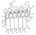
- FIG. 1is a perspective view of a first embodiment of a reaction receptacle apparatus and contact-limiting element in the form of a tiplet embodying aspects of the present invention
- FIG. 2is a side elevation of a contact-limiting tiplet
- FIG. 3is a partial bottom view of the reaction receptacle apparatus of FIG. 1 taken in the direction indicated by arrow “III” in FIG. 1;
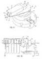
- FIG. 4is a side elevation of a first alternate embodiment of the reaction receptacle apparatus of the present invention.
- FIG. 5is a top view of the reaction receptacle apparatus of FIG. 4;
- FIG. 6is a cross-section in the direction “VI—VI” of FIG. 4;
- FIG. 7is a cross-section in the direction “VII—VIII” in FIG. 4;
- FIG. 8is a cross-section in the direction “VIII—VIII” in FIG. 4;
- FIG. 9is a perspective view of an exemplary reaction receptacle apparatus manipulating device for manipulating a reaction receptacle apparatus according to the present invention.
- FIG. 10is a side elevation, partially in cross-section, of the manipulating device of FIG. 9 with a reaction receptacle apparatus resident therein;
- FIG. 11is a side elevation, partially in cross-section, of an exemplary reaction receptacle apparatus processing device for processing a reaction receptacle apparatus according to the present invention
- FIG. 12is a partial side view of a reaction receptacle apparatus according to the present invention and a skewed wobbler plate for imparting an oscillatory vibration to the apparatus;
- FIG. 13is a cross-section showing a reaction receptacle apparatus according to the present invention carried by a receptacle carrier structure within a receptacle apparatus processing device with a tubular element of the processing device engaging a contact-limiting tiplet disposed within a contact-limiting holding structure of the apparatus of the present invention;
- FIG. 14is a cross-section showing the reaction receptacle apparatus disposed within the receptacle carrier structure with the tubular elements and the contact-limiting tiplet disposed on the end of the tubular element inserted into the apparatus;
- FIG. 15is a perspective view of a second alternate embodiment of a reaction receptacle apparatus of the present invention.
- FIG. 16is a perspective view of a third alternate embodiment of a reaction receptacle apparatus of the present invention.
- FIG. 17is a side elevation of an alternate embodiment of a contact-limiting tiplet engaged by a tubular element t of a substance transfer device.
- a preferred embodiment of a reaction receptacle apparatusis designated generally by the reference character 160 .
- the reaction receptacle apparatus 160preferably comprises a plurality of individual receptacles 162 .
- the reaction receptacle apparatus 160includes five individual receptacles 162 , but a reaction receptacle according to the present invention may include any number of receptacles 162 , as desired. Ten receptacles 162 are preferred and five receptacles 162 are most preferred.
- Each individual receptacle 162preferably has a construction similar to that of a conventional test-tube, i.e., a cylindrical body with a circular open mouth 161 and a rounded closed bottom end 163 .
- Each individual receptaclecan, however, have other shapes, such as rectangular, octagonal, etc., and may have an upper end equipped with a closable lid structure or the like.
- the reaction receptacleincludes a plurality of receptacles, the receptacles may have the same or different shapes and sizes.
- the receptacles 162are preferably oriented in an aligned arrangement comprising a single row of receptacles 162 and are connected to one another by a connecting rib structure 164 which defines a downwardly facing shoulder 165 extending longitudinally along either side of the reaction receptacle apparatus 160 .
- the receptacles 162may be oriented in a different nonlinear arrangement, or a single reaction receptacle apparatus may comprise more than one row of receptacles 162 .
- Reaction receptacle apparatus 160is preferably a single, integral piece formed of injection molded polypropylene.
- the most preferred polypropyleneis sold by Montell Polyolefins, of Wilmington, Del., product number PD701NW.
- the Montell materialis used because it is readily moldable and is chemically compatible with the preferred biological assays performed in the reaction receptacle apparatus.
- the Montell materialexperiences a limited number of static discharge events, which is important when the results of the assay performed in the reaction receptacle apparatus are determined by the detection of light emitted by the contents of the apparatus at the conclusion of the assay. Static discharge events can interfere with accurate detection or quantification of the light output.
- An arcuate shield structure 185 provided at one end of the reaction receptacle apparatus 160includes an upper portion 169 and a lower portion 173 .
- a receptacle apparatus manipulating structure 166adapted to be engaged by a reaction receptacle manipulating device, extends from the shield upper portion 169 .
- Receptacle apparatus manipulating structure 166comprises a laterally extending plate 168 extending from shield upper portion 169 with a transverse piece 167 on the opposite end of the plate 168 .
- a gusset wall 183extends downwardly from lateral plate 168 between shield lower portion 173 and transverse piece 167 .
- the shield lower portion 173 and transverse piece 167have mutually facing convex surfaces.
- the reaction receptacle apparatus 160is preferably engaged by manipulating devices and other components, as will be described below, by moving an engaging member of the manipulating device laterally (in the direction “A”) into a space 50 between the shield lower portion 173 and the transverse piece 167 .
- the convex surfaces of the shield lower portion 173 and transverse piece 167provide for wider points of entry for an engaging member undergoing a lateral relative motion into the space 50 .
- Vertically extending, raised arcuate ridges 171 , 172may be provided in the middle of the convex surfaces of the transverse piece 167 and shield lower portion 173 , respectively. The purpose of ridges 171 , 172 will be described below.
- a label-receiving structure 174 provided on an end of the reaction receptacle apparatus 160 opposite receptacle apparatus manipulating structure 166preferably includes an upper portion 71 and a lower portion 75 , which together present a flat label-receiving surface 175 .
- the label-receiving structure 174further includes a vertical gusset wall 78 extending between upper portion 71 and the endmost receptacle 162 to provide a brace for the upper portion 71 . As best shown in FIG.
- a gusset wall 80 of the label-receiving structure 174is oriented vertically and extends diagonally from a location proximate rib structure 164 toward a lower end of lower portion 75 to provide a brace for lower portion 75 .
- Labelssuch as machine-scannable bar codes, can be applied to the surface 175 to provide identifying and instructional information on the reaction receptacle apparatus 160 . Labels can be applied to surface 175 by any suitable means, such as, printing them onto surface 175 or adhering a label sheet, by means of an adhesive, to surface 175 .
- Substancescan be dispensed into or removed from the receptacles 162 through their open mouths 161 by means of a substance transfer device, such as a pipetting or aspirating apparatus (hereinafter referred to collectively as “pipetting apparatus” or “pipette”).
- the pipetting apparatusmay include a slender tubular element (see, e.g., tubular element 220 in FIG. 11) that is inserted into the receptacle 162 through the open mouth 161 and which may come into contact with the receptacle 162 itself, the substance contained in the receptacle 162 , and/or the substance being dispensed into the receptacle.
- a pipetting apparatusmay be used to dispense substances into and/or remove substances from multiple individual receptacles 162 . Accordingly, to reduce the likelihood of cross-contamination between individual receptacles 162 , it is desirable to limit the amount of the pipetting apparatus that comes into contact with the substance or walls of any receptacle 162 . Therefore, a contact-limiting element, which may take the form of a protective disposable tip, or tiplet, covers the end of the tubular element of the pipetting apparatus. One contact-limiting element is used to cover the end of the tubular element while the pipetting apparatus engages one individual receptacle to dispense substance into or withdraw substance from the receptacle. Before the pipetting apparatus moves to the next receptacle, that contact-limiting element is discarded or stored for later use with that receptacle, and a new contact-limiting element is engaged by the tubular element.
- a preferred embodiment of a contact-limiting elementcomprises a tiplet 170 .
- tiplet 170comprises a tubular body 179 having a peripheral flange 177 , preferably extending radially with respect to said tubular body 179 , and a thickened wall portion 178 , adjacent the peripheral flange 177 , having a generally larger diameter than a remaining portion of the tubular body 179 of the tiplet 170 .
- An axially extending inner bore 180passes through the tiplet 170 .
- Bore 180includes an outwardly flared end 181 , which facilitates insertion of a bottom free end of a tubular element of a pipetting apparatus into the bore 180 of tiplet 170 .
- the inner diameter of inner bore 180provides an interference fit with the outer diameter of the tubular element to frictionally secure tiplet 170 onto the tubular element when the bottom end of the tubular element is forced into the inner bore 180 .
- the tubular body 179 and inner bore 180are generally cylindrical in shape, consistent with the typically cylindrical shape of the tubular element of a substance transfer device, such as a pipetting or aspirating device.
- the present inventionis not limited, however, to contact-limiting elements having tubular bodies and inner bores that are cylindrical, as the tubular body and inner bore of the contact-limiting element may have a shape that is other than cylindrical to conform to non-cylindrical tubular elements of substance transfer devices.
- the bottom end of the tiplet 170preferably includes a beveled portion 182 .
- the beveled portion 182will prevent a vacuum from forming between the end of the tiplet 170 and the bottom 163 of the receptacle 162 .
- Tiplet 470comprises a tubular body 479 having a peripheral flange 477 , preferably extending radially with respect to said tubular body 479 , and a thickened wall portion 478 , adjacent the peripheral flange 477 , of generally larger diameter than a remaining portion of the tubular body 479 of the tiplet 470 .
- An axially extending inner bore 480passes through the tiplet 470 .
- Bore 480includes a bevelled end 481 , which facilitates insertion of an upper end 483 of the tubular body 479 into a bottom free end of a tubular element 420 .
- the outer diameter of upper end 483 of the tubular body 479provides an interference fit with the inner diameter of the tubular element 420 to frictionally secure tiplet 470 onto the tubular element 420 when the upper end 483 of the tubular body 479 is inserted into the bottom free end of the tubular element 420 .
- tubular body 479 and inner bore 480need not necessarily be generally cylindrical in shape, as illustrated in FIG. 17, may have a shape that is other than cylindrical to conform to non-cylindrical tubular elements of substance transfer devices.
- the bottom end of the tiplet 470preferably includes a beveled portion 482 .
- the beveled portion 482will prevent a vacuum from forming between the end of the tiplet 470 and the bottom 163 of the receptacle 162 .
- the reaction receptacle apparatus 160preferably includes contact-limiting element holding structures in the form of tiplet holding structures 176 adjacent the open mouth 161 of each respective receptacle 162 .
- Each tiplet holding structure 176provides an elongated orifice 150 , preferably generally cylindrical in shape, within which is received a contact-limiting tiplet 170 ( 470 ).
- An annular end face 152extends about the orifice 150 , and when the tiplet 170 ( 470 ) is inserted into a tiplet holding structure 176 , the peripheral flange 177 ( 477 ) contacts the end face 152 of tiplet holding structure 176 to limit the depth to which the tiplet 170 ( 470 ) can be inserted into the orifice 150 .
- the outside diameter of the thickened wall portion 178 ( 478 )is slightly larger than inside diameter of the orifice 150 .
- a plurality of small, raised ribs 154extend longitudinally along the inner wall of the orifice 150 at different circumferentially-spaced positions.
- the crests of the raised ribs 154define an inner diameter that is slightly smaller than the outer diameter of the thickened wall portion 178 ( 478 ). Accordingly, the tiplet holding structure 176 provides a sliding interference fit between the thickened wall portion 178 ( 478 ) and the inner diameter of the orifice 150 or between the thickened wall portion 178 ( 478 ) and the crests of the ribs 154 .
- tiplet 170 ( 470 )is held securely within the orifice 150 of the tiplet holding structure 176 so the tiplet 170 ( 470 ) is unlikely to dislodge from the tiplet holding structure 176 , even if the reaction receptacle apparatus 160 is inverted.
- the tiplet 170 ( 470 )is frictionally engaged by the tubular element of a pipetting apparatus while the tiplet 170 ( 470 ) is held in the tiplet holding structure 176 , the frictional hold between the tiplet 170 ( 470 ) and the tubular element is greater than the frictional hold between the tiplet 170 ( 470 ) and the tiplet holding structure 176 .
- the tiplet 170 ( 470 )should remain secured on the end of the tubular element when the tubular element is withdrawn in an axial direction from the orifice 150 of the tiplet holding structure 176 .
- tiplet 170the embodiment shown in FIG. 2
- tiplet 470the embodiment shown in FIG. 17
- FIGS. 4 and 5An alternate tiplet holding structure 76 is shown in FIGS. 4 and 5.
- Reaction receptacle apparatus 60includes a tiplet holding structure 76 that is different from the tiplet holding structure 176 of reaction receptacle apparatus 160 of FIG. 1 . In all other respects, however, reaction receptacle apparatus 60 is identical to reaction receptacle apparatus 160 .
- Tiplet holding structure 76includes a tiplet-receiving orifice 79 with an end face 77 surrounding orifice 79 and forming a partial annulus.
- a slot 78extends longitudinally along a wall of the tiplet holding structure 76 .
- Slot 78allows the tiplet holding structure 76 to expand when a tiplet 170 is inserted into the tiplet holding structure 76 , and the resiliency of the material of which the reaction receptacle apparatus 60 is formed provides a frictional fit between a tiplet 170 and the tiplet holding structure 76 .
- connecting rib structure 164extends along both sides of the reaction receptacle apparatus 160 and defines downwardly facing shoulders 165 with outer edges 192 along each side of the reaction receptacle apparatus 160 ( 60 ).
- the reaction receptacle apparatus 160 ( 60 )is operatively supported within a diagnostic instrument or the like by means of the shoulders 165 resting on parallel, horizontal flanges spaced apart from one another by a distance slightly greater than the width of the individual receptacle 162 , but less than the width of the rib structure 164 between edges 192 .
- Such flangesmay be defined by a slot extending from an edge of a reaction receptacle apparatus supporting plate.
- the reaction receptacle apparatusmay be inserted into and removed from a supporting structure by a reaction receptacle apparatus manipulating device.
- two upwardly angled portions 82provide upwardly angled shoulders 84 on both sides of the reaction receptacle apparatus 160 ( 60 ).
- the upwardly angled shoulders 84facilitate sliding of the reaction receptacle apparatus 160 ( 60 ) onto a supporting structure.
- FIGS. 9 and 10An exemplary device 20 for manipulating a reaction receptacle apparatus 160 ( 60 ) is shown in FIGS. 9 and 10.
- the device 20includes a base structure 22 attached to a mounting bracket or mounting plate of an instrument which processes the contents of numerous reaction receptacle apparatuses according to the present invention and may perform one or more assays within each reaction receptacle apparatus 160 .
- the manipulating device 20moves the reaction receptacle apparatuses from one location to another within the instrument.
- the manipulating device 20further includes a rotating transport carrier 28 which rotates about a shaft 25 by means of a stepper motor 24 which turns a pulley 29 attached to the shaft 25 via a drive belt 27 .
- the shaft 25 and pulley 29may be covered by a pulley housing 26 .
- the rotating transport carrier 28includes a base plate 30 covered by a housing 32 .
- the housing 32includes an opening 36 at one end thereof, and the base plate 30 includes a slot 31 formed therein.
- a manipulating hook 34is mounted for sliding translation in the slot 31 and is attached to a threaded drive screw 40 that is actuated by a stepper motor 38 to extend and retract the manipulating hook 34 within the slot 31 .
- the manipulating hook 34is extended to a forward position projecting from the opening 36 as shown in FIG. 9.
- a lateral translation of the manipulating hook 34is effected, such as by effecting a small rotation of the rotating transport carrier 28 , to place the manipulating hook 34 in the space 50 between the lower portion 173 of the arcuate shield structure 185 and the transverse piece 167 of the receptacle apparatus manipulating structure 166 .
- the stepper motor 38retracts the drive screw 40 , pulling the manipulating hook 34 and the reaction receptacle apparatus 160 back into the rotating transport carrier 28 .
- the downwardly facing shoulders 165 defined by the connecting rib structure 164 of the reaction receptacle apparatus 160are supported by the base plate 30 along opposite edges 42 of the slot 31 , thus supporting the reaction receptacle apparatus 160 in the rotating transport carrier 28 .
- the carrier 28With the reaction receptacle apparatus 160 secured within the rotating transport carrier 28 , the carrier 28 can be rotated by the stepper motor 24 to a different position at which the stepper motor 38 can extend the drive screw 40 and the manipulating hook 34 to push the reaction receptacle apparatus 160 out of the rotating transport carrier 28 and into a different location within the instrument.
- Processing device 200may represent one of many similar or related devices which together make up a reaction receptacle processing instrument.
- the processing device 200includes a housing 201 with an opening 202 formed therein.
- a reaction receptacle apparatus 160can be inserted into the processing device 200 through the opening 202 and removed through the opening 202 by a manipulating device such as the manipulating device 20 shown in FIGS. 9 and 10 and described above.
- a manipulating devicesuch as the manipulating device 20 shown in FIGS. 9 and 10 and described above.
- Inside the housing 201the reaction receptacle apparatus is supported by a receptacle carrier structure 206 having a base plate 204 (see also FIGS. 13 and 14) with a receptacle receiving slot (not shown) formed therein so that the reaction receptacle apparatus 160 can be supported by means of portions of the plate 204 along opposite edges of the slot supporting the connecting rib structure 164 of the reaction receptacle apparatus 160 .
- Processing device 200may be a mixing device for mixing the contents of the reaction receptacle apparatus 160 ; the processing device 200 may be a dispensing device for simultaneously dispensing substance into each of the individual receptacles 162 of the reaction receptacle apparatus 160 ; or the processing device 200 may be a device for simultaneously aspirating substance from each of the receptacles 162 of the reaction receptacle apparatus 160 .
- the processing device 200may perform any combination of two or more of the above functions.
- the receptacle carrier structure 206may be coupled to an orbital mixing assembly comprising a stepper motor 208 , a drive wheel 210 with an eccentric pin 212 extending therefrom, and an idler wheel 216 having an eccentric pin 218 and being coupled to the drive wheel 210 by means of a belt 214 .
- the stepper motor 208rotates the drive pulley 210 which in turn rotates the idler pulley 216
- the eccentric pins 212 and 218engage the receptacle carrier structure 206 thus moving the receptacle carrier structure and the reaction receptacle apparatus 160 carried thereby in an orbital path of motion. Movement at a sufficiently high frequency can cause sufficient agitation of the reaction receptacle apparatus 160 to mix the contents thereof.
- lateral ribs 190extend longitudinally along the outer walls of the receptacles 162 above the connecting rib structure 164 at diametrically opposed positions with respect to one another.
- the outer edges of the lateral ribs 190are generally co-planar with the outer edges 192 of the connecting rib structure 164 .
- the lateral ribsprovide additional strength and rigidity to the open mouth 161 of the receptacle 162 .
- the outer edges of the lateral ribs 190can engage the sidewalls of a receptacle carrier structure 206 , as shown in FIGS.
- lateral ribs 190be provided on each of the receptacles 162 , lateral ribs 190 , when included, can be provided on less than all of the receptacles 162 as well.
- the reaction receptacle apparatus 160can be engaged by a dispensing and/or aspirating system comprising an array of tubular elements 220 .
- the dispensing and/or aspirating systempreferably includes five tubular elements 220 oriented so as to correspond to the orientations of the individual receptacles 162 of the reaction receptacle apparatus 160 .
- the tubular elements 220are coupled to means for providing vertical movement of the free ends of the tubular elements 220 with respect to the reaction receptacle apparatus 160 to move the ends of the tubular elements 220 into and out of the individual receptacles 162 to aspirate and/or dispense substances.
- tubular elements 220are coupled to means, such as a fluid pump and fluid source or a vacuum pump, for delivering fluid to each of the tubular elements 220 or providing a suction at each of the tubular elements 220 .
- a contact-limiting tiplet 170be placed on the end of each tubular element 220 .
- the tubular elements 220are first lowered to simultaneously engage all of the tiplets 170 carried in their respective tiplet holding structures 176 .
- the array of tubular elements 220can be coupled to means for providing lateral translation of the tubular elements 220 for moving the tubular elements 220 to a position above the tiplet holding structures 176 .
- the receptacle carrier structure 206itself can be moved laterally to place the tiplet holding structures 176 below the respective tubular elements 220 .
- the stepper motor 208can move the assembly a limited number of steps, thus moving the receptacle carrier structure 206 and the reaction receptacle apparatus 160 a portion of one orbital path to place the tiplet holding structures 176 below the tubular elements 220 as shown in FIG. 13 .
- each of the respective tiplet holding structures 176 ( 76 )is preferably disposed at a position between adjacent receptacles 162 . Locating the tiplet holding structures 176 ( 76 ) between the adjacent receptacles 162 places the tubular elements 220 on the orbital paths of the contact-limiting element holding structures 176 ( 76 ) as the reaction receptacle apparatus 160 is moved with respect to the pipettes 220 . Thus, the orbital mixer assembly can be used to properly position the tiplet holding structures 176 ( 76 ) with respect to the tubular elements 220 , as described above.
- placing the tiplet holding structures 176 ( 76 ) between adjacent receptacles 162provides for a narrower profile of the reaction receptacle apparatus 160 ( 60 ) than if the tiplet holding structures 176 ( 76 ) were located on the outer portion of the receptacles 162 nearest the edge 192 of the connecting rib structure 164 .
- the processing device 200may also include an array of fixed nozzles 222 for dispensing substances into the receptacles 162 of the reaction receptacle apparatus 160 held in the receptacle carrier structure 206 .
- an alternate, oscillating mixing device 230comprises a skewed wobbler plate 232 disposed on a shaft 234 driven by a motor (not shown).
- the reaction receptacle apparatus 160carried by a carrier structure (not shown), is moved with respect to the oscillating mixing device 230 —or the oscillating mixing 230 is moved with respect to the reaction receptacle apparatus 160 —until the wobbler plate 232 is disposed in the space 50 between the lower portion 173 of the arcuate shield structure 185 and the transverse piece 167 of the receptacle apparatus manipulating structure 166 .
- the shaft 234rotates, the position of the portion of the wobbler plate 232 engaged with the receptacle apparatus 160 varies in a linearly oscillating manner to impart a linear oscillating motion to the reaction receptacle apparatus 160 .
- the raised ridges 171 , 172 provided in the middle of the convex surfaces of the transverse piece 167 and the lower portion 173 , respectively,can minimize the surface contact between the wobbler plate 232 and the convex surfaces, thus limiting friction therebetween. It has been determined, however, that raised ridges 171 , 172 can interfere with the engagement of the manipulating hook 34 of a manipulating device 20 with the apparatus manipulating structure 166 . Therefore, raised ridges 171 , 172 are preferably omitted.
- a linear array of individual receptacles 162are integrally coupled together by the connecting rib structure 164 .
- the broadest aspects of the present inventioncontemplate a reaction receptacle apparatus 260 , as shown in FIG. 15, which comprises a single receptacle 262 having an open-mouth 261 and a connected contact-limiting element holding structure, such as tiplet holding structure 276 , attached to the receptacle 262 .
- tiplet holding structure 276includes a tiplet receiving orifice 279 , a longitudinal slot 278 , and an end-face 277 forming a portion of an annulus.
- the contact-limiting element holding structuremay be in the form of tiplet holding structure 176 of FIG. 1, in which no longitudinal slot is formed therein and in which a plurality of longitudinally extending raised ribs 154 (see FIG. 3) are formed on the inner surface of the orifice 150 .
- reaction receptacle apparatus 360includes a plurality of individual receptacles 362 , each having an open receptacle mouth 361 .
- the most preferred embodiment of the reaction receptacle apparatus 360includes five individual receptacles 362 .
- Individual receptacles 362are connected to one another by a connecting rib structure 364 .
- Reaction receptacle apparatus 360is in most respects identical to the reaction receptacle apparatuses described above and shown in FIGS. 1, 4 , and 5 , except that reaction receptacle apparatus 360 does not include contact-limiting holding structures 176 ( 76 ) associated with each individual receptacle 362 . Nor does reaction receptacle apparatus 360 include a contact-limiting element, such as tiplet 170 , associated with each individual receptacle 362 .
- Reaction receptacle apparatus 360also preferably includes a label-receiving structure 374 having an upper portion 377 and a lower portion 375 cooperating so as to define a flat label-receiving surface 376 .
- a vertical gusset wall 378extends between the upper portion 377 of label-receiving structure 374 and the outer wall of the endmost individual receptacle 362 .
- reaction receptacle apparatus 360includes an arcuate shield structure 385 having an upper portion 369 and a lower portion 373 .
- a receptacle apparatus manipulating structure 366includes a transverse piece 367 connected to the arcuate shield structure 385 by means of a plate 368 extending between upper portion 369 of arcuate shield structure 385 and transverse piece 367 , and a gusset wall 383 extending between the lower portion 373 of the arcuate shield structure 385 and the transverse piece 367 of the receptacle apparatus manipulating structure 366 .
- the transverse piece 367 and the lower portion 373 of the arcuate shield structure 385preferably have mutually-facing convex surfaces, and the surfaces may include vertical arcuate ridges 371 and 372 , respectively.
- the receptacle apparatus manipulating structure 366 and the arcuate ridges 371 and 372 of the reaction receptacle apparatus 360serve the same function as the receptacle apparatus manipulating structure 166 and the raised arcuate ribs 171 and 172 described above.
- the reaction receptacle apparatus 360may further include connecting walls 380 extending between adjacent individual receptacles 362 at upper portions thereof above the connecting rib structure 364 .
- a gusset wall 382may be provided between the endmost individual receptacle 362 and the arcuate shield structure 385 .
- the reaction receptacle apparatus 360may further include lateral ribs 390 extending vertically along the outer surfaces of diametrically opposed positions of upper portions of the individual receptacles 362 .
- the lateral ridges 390 of the reaction receptacle apparatus 360serve the same function as do the lateral ribs 190 described above.
Landscapes
- Health & Medical Sciences (AREA)
- Chemical & Material Sciences (AREA)
- Immunology (AREA)
- Life Sciences & Earth Sciences (AREA)
- Chemical Kinetics & Catalysis (AREA)
- Engineering & Computer Science (AREA)
- Clinical Laboratory Science (AREA)
- Molecular Biology (AREA)
- Physics & Mathematics (AREA)
- Pathology (AREA)
- Hematology (AREA)
- General Physics & Mathematics (AREA)
- Biomedical Technology (AREA)
- Urology & Nephrology (AREA)
- General Health & Medical Sciences (AREA)
- Biochemistry (AREA)
- Analytical Chemistry (AREA)
- Biotechnology (AREA)
- Medicinal Chemistry (AREA)
- Food Science & Technology (AREA)
- Microbiology (AREA)
- Cell Biology (AREA)
- Automatic Analysis And Handling Materials Therefor (AREA)
- Apparatus Associated With Microorganisms And Enzymes (AREA)
- Feeding, Discharge, Calcimining, Fusing, And Gas-Generation Devices (AREA)
- Sampling And Sample Adjustment (AREA)
- Separation Using Semi-Permeable Membranes (AREA)
Abstract
Description
Claims (48)
Priority Applications (2)
| Application Number | Priority Date | Filing Date | Title |
|---|---|---|---|
| US09/557,574US6517782B1 (en) | 1997-05-02 | 2000-04-21 | Reaction receptacle apparatus |
| US09/802,648US6517783B2 (en) | 1997-05-02 | 2001-03-09 | Reaction receptacle apparatus |
Applications Claiming Priority (3)
| Application Number | Priority Date | Filing Date | Title |
|---|---|---|---|
| US4680097P | 1997-05-02 | 1997-05-02 | |
| US09/070,726US6086827A (en) | 1997-05-02 | 1998-05-01 | Reaction receptacle apparatus |
| US09/557,574US6517782B1 (en) | 1997-05-02 | 2000-04-21 | Reaction receptacle apparatus |
Related Parent Applications (1)
| Application Number | Title | Priority Date | Filing Date |
|---|---|---|---|
| US09/070,726ContinuationUS6086827A (en) | 1997-05-02 | 1998-05-01 | Reaction receptacle apparatus |
Related Child Applications (1)
| Application Number | Title | Priority Date | Filing Date |
|---|---|---|---|
| US09/802,648ContinuationUS6517783B2 (en) | 1997-05-02 | 2001-03-09 | Reaction receptacle apparatus |
Publications (1)
| Publication Number | Publication Date |
|---|---|
| US6517782B1true US6517782B1 (en) | 2003-02-11 |
Family
ID=21945462
Family Applications (3)
| Application Number | Title | Priority Date | Filing Date |
|---|---|---|---|
| US09/070,726Expired - LifetimeUS6086827A (en) | 1997-05-02 | 1998-05-01 | Reaction receptacle apparatus |
| US09/557,574Expired - LifetimeUS6517782B1 (en) | 1997-05-02 | 2000-04-21 | Reaction receptacle apparatus |
| US09/802,648Expired - LifetimeUS6517783B2 (en) | 1997-05-02 | 2001-03-09 | Reaction receptacle apparatus |
Family Applications Before (1)
| Application Number | Title | Priority Date | Filing Date |
|---|---|---|---|
| US09/070,726Expired - LifetimeUS6086827A (en) | 1997-05-02 | 1998-05-01 | Reaction receptacle apparatus |
Family Applications After (1)
| Application Number | Title | Priority Date | Filing Date |
|---|---|---|---|
| US09/802,648Expired - LifetimeUS6517783B2 (en) | 1997-05-02 | 2001-03-09 | Reaction receptacle apparatus |
Country Status (11)
| Country | Link |
|---|---|
| US (3) | US6086827A (en) |
| EP (1) | EP0979146B1 (en) |
| JP (3) | JP2001524214A (en) |
| KR (1) | KR20010012479A (en) |
| AT (2) | ATE224770T1 (en) |
| AU (1) | AU735267B2 (en) |
| CA (1) | CA2287962C (en) |
| DE (2) | DE69827678T2 (en) |
| DK (2) | DK0979146T3 (en) |
| ES (2) | ES2231589T3 (en) |
| WO (1) | WO1998050158A1 (en) |
Cited By (27)
| Publication number | Priority date | Publication date | Assignee | Title |
|---|---|---|---|---|
| US20010019826A1 (en)* | 1998-05-01 | 2001-09-06 | Gen-Probe Incorporated | Automated diagnostic analyzer and method |
| US20030129095A1 (en)* | 2002-01-04 | 2003-07-10 | Farina Edward Francis | Stackable aliquot vessel array |
| USD492419S1 (en) | 2002-09-20 | 2004-06-29 | Dade Behring Inc. | Stackable aliquot vessel array |
| US20060018802A1 (en)* | 2004-07-09 | 2006-01-26 | Greenway Roger B Jr | Method and apparatus for reconfiguring a labware storage system |
| US20060210433A1 (en)* | 2005-03-10 | 2006-09-21 | Gen-Probe Incorporated | Signal measuring system having a movable signal measuring device |
| US20080063573A1 (en)* | 1998-05-01 | 2008-03-13 | Gen-Probe Incorporated | Temperature-Controlled Incubator Having A Receptacle Mixing Mechanism |
| AU2006230729B2 (en)* | 1998-05-01 | 2008-04-03 | Gen-Probe Incorporated | Transport mechanism |
| US20080251490A1 (en)* | 2007-04-16 | 2008-10-16 | Bd Diagnostics | Pierceable cap |
| US20080251489A1 (en)* | 2007-04-16 | 2008-10-16 | Becton, Dickinson And Company | Pierceable cap |
| US20090208966A1 (en)* | 2001-03-09 | 2009-08-20 | Gen-Probe Incorporated | Method for removing a fluid substance from a closed system |
| USD675748S1 (en)* | 2012-03-07 | 2013-02-05 | Perkinelmer Health Services, Inc. | Testing rack |
| US20140014654A1 (en)* | 2011-03-18 | 2014-01-16 | Schott Schweiz Ag | Carrier plate and transporting and/or storing device for pharmaceutical containers |
| US8718948B2 (en) | 2011-02-24 | 2014-05-06 | Gen-Probe Incorporated | Systems and methods for distinguishing optical signals of different modulation frequencies in an optical signal detector |
| USD707847S1 (en)* | 2010-01-22 | 2014-06-24 | Biotix, Inc. | Anti-static pipette tip tray assembly |
| US9046507B2 (en) | 2010-07-29 | 2015-06-02 | Gen-Probe Incorporated | Method, system and apparatus for incorporating capacitive proximity sensing in an automated fluid transfer procedure |
| US9089845B2 (en) | 2009-01-23 | 2015-07-28 | Biotix, Inc. | Anti-static pipette tip trays |
| US9335338B2 (en) | 2013-03-15 | 2016-05-10 | Toshiba Medical Systems Corporation | Automated diagnostic analyzers having rear accessible track systems and related methods |
| US9400285B2 (en) | 2013-03-15 | 2016-07-26 | Abbot Laboratories | Automated diagnostic analyzers having vertically arranged carousels and related methods |
| US9513303B2 (en) | 2013-03-15 | 2016-12-06 | Abbott Laboratories | Light-blocking system for a diagnostic analyzer |
| US9632103B2 (en) | 2013-03-15 | 2017-04-25 | Abbott Laboraties | Linear track diagnostic analyzer |
| USD815753S1 (en) | 2014-12-10 | 2018-04-17 | Biotix, Inc. | Pipette tip sheet |
| US9993820B2 (en) | 2013-03-15 | 2018-06-12 | Abbott Laboratories | Automated reagent manager of a diagnostic analyzer system |
| US10001497B2 (en) | 2013-03-15 | 2018-06-19 | Abbott Laboratories | Diagnostic analyzers with pretreatment carousels and related methods |
| US10137453B2 (en) | 2014-12-10 | 2018-11-27 | Biotix, Inc. | Static-defeating apparatus for pipette tips |
| USD849962S1 (en) | 2014-12-10 | 2019-05-28 | Biotix, Inc. | Pipette tip retention sheet |
| USD865216S1 (en) | 2014-12-10 | 2019-10-29 | Biotix, Inc. | Pipette tip sheet |
| US10730053B2 (en) | 2014-12-10 | 2020-08-04 | Biotix, Inc. | Static-defeating apparatus for pipette tips |
Families Citing this family (87)
| Publication number | Priority date | Publication date | Assignee | Title |
|---|---|---|---|---|
| US6048734A (en) | 1995-09-15 | 2000-04-11 | The Regents Of The University Of Michigan | Thermal microvalves in a fluid flow method |
| DE69827678T2 (en)* | 1997-05-02 | 2005-10-06 | Gen-Probe Inc., San Diego | Reaction vessel apparatus |
| US6415669B1 (en)* | 1998-04-09 | 2002-07-09 | Ccs Packard, Inc. | Dispensing apparatus having means for loading pipette tips in a dispense head |
| JP2000046841A (en)* | 1998-07-31 | 2000-02-18 | Tosoh Corp | Automatic measuring device |
| DE60030310T2 (en)* | 1999-10-20 | 2007-08-23 | Gentra Systems Inc., Minneapolis | MIXING AND CASTING APPARATUS WITH ROTATABLE ARM AND ASSOCIATED VESSEL |
| US6846293B2 (en)* | 2000-12-05 | 2005-01-25 | Bradley S. Butler | Spinal fluid collection system |
| US6692700B2 (en) | 2001-02-14 | 2004-02-17 | Handylab, Inc. | Heat-reduction methods and systems related to microfluidic devices |
| US6852287B2 (en) | 2001-09-12 | 2005-02-08 | Handylab, Inc. | Microfluidic devices having a reduced number of input and output connections |
| US7829025B2 (en) | 2001-03-28 | 2010-11-09 | Venture Lending & Leasing Iv, Inc. | Systems and methods for thermal actuation of microfluidic devices |
| US7010391B2 (en) | 2001-03-28 | 2006-03-07 | Handylab, Inc. | Methods and systems for control of microfluidic devices |
| US8895311B1 (en) | 2001-03-28 | 2014-11-25 | Handylab, Inc. | Methods and systems for control of general purpose microfluidic devices |
| US7323140B2 (en) | 2001-03-28 | 2008-01-29 | Handylab, Inc. | Moving microdroplets in a microfluidic device |
| US7488303B1 (en)* | 2002-09-21 | 2009-02-10 | Glaukos Corporation | Ocular implant with anchor and multiple openings |
| US6626051B2 (en)* | 2001-08-14 | 2003-09-30 | Investigen Biotechnologies, Inc. | Lid for sample holder |
| DE10207847A1 (en)* | 2002-02-15 | 2003-08-28 | Zeiss Carl Jena Gmbh | Ejection device for a climate chamber, in particular for holding microtiter plates (MTP) |
| US7514270B2 (en)* | 2002-04-12 | 2009-04-07 | Instrumentation Laboratory Company | Immunoassay probe |
| US7211224B2 (en)* | 2002-05-23 | 2007-05-01 | Millipore Corporation | One piece filtration plate |
| US6808304B2 (en)* | 2002-08-27 | 2004-10-26 | Dade Behring Inc. | Method for mixing liquid samples using a linear oscillation stroke |
| US7046357B2 (en)* | 2003-01-30 | 2006-05-16 | Ciphergen Biosystems, Inc. | Apparatus for microfluidic processing and reading of biochip arrays |
| EP1443330A1 (en)* | 2003-02-03 | 2004-08-04 | Gilson Sas | Methods, rack and device for preparing samples for analysis |
| EP2407243B1 (en) | 2003-07-31 | 2020-04-22 | Handylab, Inc. | Multilayered microfluidic device |
| ITMI20040743A1 (en)* | 2004-04-15 | 2004-07-15 | Cs Automazione S R L | STORAGE SYSTEM HOMOGENIZATION AND DOSAGE |
| CA2994321C (en)* | 2004-05-03 | 2023-08-08 | Handylab, Inc. | A microfluidic device and methods for processing polynucleotide-containing samples |
| US8852862B2 (en) | 2004-05-03 | 2014-10-07 | Handylab, Inc. | Method for processing polynucleotide-containing samples |
| US8211386B2 (en) | 2004-06-08 | 2012-07-03 | Biokit, S.A. | Tapered cuvette and method of collecting magnetic particles |
| EP2348320B1 (en) | 2005-03-10 | 2024-05-01 | Gen-Probe Incorporated | Methods and systems for detecting multiple fluorescent emission signals |
| EP1895305A1 (en)* | 2005-05-17 | 2008-03-05 | Wako Pure Chemical Industries, Ltd. | Connected reagent container |
| JP2009511059A (en)* | 2005-10-11 | 2009-03-19 | ハンディーラブ インコーポレイテッド | Polynucleotide sample preparation device |
| GB0521851D0 (en)* | 2005-10-26 | 2005-12-07 | Genial Genetic Solutions Ltd | Biological apparatus |
| JP4548359B2 (en)* | 2006-02-20 | 2010-09-22 | 株式会社島津製作所 | Reaction kit processing equipment |
| US11806718B2 (en) | 2006-03-24 | 2023-11-07 | Handylab, Inc. | Fluorescence detector for microfluidic diagnostic system |
| US8088616B2 (en) | 2006-03-24 | 2012-01-03 | Handylab, Inc. | Heater unit for microfluidic diagnostic system |
| US10900066B2 (en) | 2006-03-24 | 2021-01-26 | Handylab, Inc. | Microfluidic system for amplifying and detecting polynucleotides in parallel |
| US7998708B2 (en) | 2006-03-24 | 2011-08-16 | Handylab, Inc. | Microfluidic system for amplifying and detecting polynucleotides in parallel |
| WO2007112114A2 (en) | 2006-03-24 | 2007-10-04 | Handylab, Inc. | Integrated system for processing microfluidic samples, and method of using same |
| US8883490B2 (en) | 2006-03-24 | 2014-11-11 | Handylab, Inc. | Fluorescence detector for microfluidic diagnostic system |
| WO2008061165A2 (en) | 2006-11-14 | 2008-05-22 | Handylab, Inc. | Microfluidic cartridge and method of making same |
| US9618139B2 (en) | 2007-07-13 | 2017-04-11 | Handylab, Inc. | Integrated heater and magnetic separator |
| US20090136385A1 (en)* | 2007-07-13 | 2009-05-28 | Handylab, Inc. | Reagent Tube |
| US8105783B2 (en) | 2007-07-13 | 2012-01-31 | Handylab, Inc. | Microfluidic cartridge |
| US9186677B2 (en) | 2007-07-13 | 2015-11-17 | Handylab, Inc. | Integrated apparatus for performing nucleic acid extraction and diagnostic testing on multiple biological samples |
| EP3222733B1 (en) | 2007-07-13 | 2021-04-07 | Handylab, Inc. | Polynucleotide capture materials, and methods of using same |
| USD621060S1 (en) | 2008-07-14 | 2010-08-03 | Handylab, Inc. | Microfluidic cartridge |
| US8133671B2 (en)* | 2007-07-13 | 2012-03-13 | Handylab, Inc. | Integrated apparatus for performing nucleic acid extraction and diagnostic testing on multiple biological samples |
| US8287820B2 (en) | 2007-07-13 | 2012-10-16 | Handylab, Inc. | Automated pipetting apparatus having a combined liquid pump and pipette head system |
| US8182763B2 (en) | 2007-07-13 | 2012-05-22 | Handylab, Inc. | Rack for sample tubes and reagent holders |
| USD632799S1 (en)* | 2008-05-15 | 2011-02-15 | The Automation Partnership | Cell dispenser |
| US20100009351A1 (en)* | 2008-07-11 | 2010-01-14 | Handylab, Inc. | Polynucleotide Capture Materials, and Method of Using Same |
| USD618820S1 (en)* | 2008-07-11 | 2010-06-29 | Handylab, Inc. | Reagent holder |
| USD787087S1 (en) | 2008-07-14 | 2017-05-16 | Handylab, Inc. | Housing |
| US8076126B2 (en) | 2008-07-18 | 2011-12-13 | Ortho-Clinical Diagnostics, Inc. | Single column immunological test elements |
| US20100219093A1 (en)* | 2009-01-13 | 2010-09-02 | Biotix, Inc. | Manufacture processes for assessing pipette tip quality |
| USD638953S1 (en) | 2009-05-12 | 2011-05-31 | Invitrogen Dynal As | Laboratory apparatus |
| CN102427885B (en) | 2009-05-15 | 2016-10-19 | 简·探针公司 | Method and apparatus for automatic movement of magnets in an apparatus for performing magnetic separation procedures |
| WO2010132885A2 (en) | 2009-05-15 | 2010-11-18 | Gen-Probe Incorporated | Method and apparatus for effecting transfer of reaction receptacles in an instrument for multi-step analytical procedures |
| US8372359B2 (en)* | 2009-11-19 | 2013-02-12 | Qiagen Gaithersburg, Inc. | Sample vial retainer |
| US10788504B2 (en)* | 2010-01-11 | 2020-09-29 | Waters Technologies Corporation | Apparatus for controlling sample position in a liquid chromatography system |
| DE102010022552B4 (en)* | 2010-06-02 | 2013-06-27 | Perkinelmer Chemagen Technologie Gmbh | Device and method for the complete absorption of liquids from vessels |
| CN106190806B (en) | 2011-04-15 | 2018-11-06 | 贝克顿·迪金森公司 | Scan real-time microfluid thermal cycler and the method for synchronous thermal cycle and scanning optical detection |
| CA2849917C (en) | 2011-09-30 | 2020-03-31 | Becton, Dickinson And Company | Unitized reagent strip |
| USD692162S1 (en) | 2011-09-30 | 2013-10-22 | Becton, Dickinson And Company | Single piece reagent holder |
| WO2013067202A1 (en) | 2011-11-04 | 2013-05-10 | Handylab, Inc. | Polynucleotide sample preparation device |
| EP2810080B1 (en) | 2012-02-03 | 2024-03-27 | Becton, Dickinson and Company | External files for distribution of molecular diagnostic tests and determination of compatibility between tests |
| AU2013202804A1 (en) | 2012-06-14 | 2014-01-16 | Gen-Probe Incorporated | Use of a fluorescent material to detect failure or deteriorated performance of a fluorometer |
| AU2013202808B2 (en) | 2012-07-31 | 2014-11-13 | Gen-Probe Incorporated | System and method for performing multiplex thermal melt analysis |
| US10058866B2 (en) | 2013-03-13 | 2018-08-28 | Abbott Laboratories | Methods and apparatus to mitigate bubble formation in a liquid |
| USD978375S1 (en) | 2013-03-13 | 2023-02-14 | Abbott Laboratories | Reagent container |
| USD962471S1 (en) | 2013-03-13 | 2022-08-30 | Abbott Laboratories | Reagent container |
| US9535082B2 (en) | 2013-03-13 | 2017-01-03 | Abbott Laboratories | Methods and apparatus to agitate a liquid |
| AU2013202778A1 (en) | 2013-03-14 | 2014-10-02 | Gen-Probe Incorporated | Systems, methods, and apparatuses for performing automated reagent-based assays |
| AU2013202805B2 (en) | 2013-03-14 | 2015-07-16 | Gen-Probe Incorporated | System and method for extending the capabilities of a diagnostic analyzer |
| US9868555B2 (en)* | 2014-04-28 | 2018-01-16 | Robert F. LiVolsi | Systems and methods for filling inoculations |
| USD782061S1 (en)* | 2015-06-25 | 2017-03-21 | Abbott Laboratories | Reagent kit with multiple bottles |
| USD782060S1 (en)* | 2015-06-25 | 2017-03-21 | Abbott Laboratories | Reagent kit with multiple bottles |
| USD782063S1 (en)* | 2015-06-25 | 2017-03-21 | Abbott Laboratories | Reagent kit with multiple bottles |
| USD782062S1 (en)* | 2015-06-25 | 2017-03-21 | Abbott Laboratories | Reagent kit with multiple bottles |
| CN105842466B (en)* | 2016-03-21 | 2017-11-14 | 长春赛诺迈德医学技术有限责任公司 | Reaction cup carrier mechanism and the means of delivery |
| CN106290818B (en)* | 2016-08-31 | 2018-07-06 | 成都恩普生医疗科技有限公司 | A kind of reaction cup assembly |
| CN106399054B (en)* | 2016-11-22 | 2019-01-04 | 安图实验仪器(郑州)有限公司 | For in-vitro diagnosis equipment and with the reaction warehouse of shaped open |
| CA3155871A1 (en) | 2017-07-10 | 2019-01-17 | Gen-Probe Incorporated | Analytical systems and methods for nucleic acid amplification using sample assigning parameters |
| CN111902213B (en) | 2018-01-29 | 2022-12-06 | 简·探针公司 | Analysis system and method |
| EP3820616A1 (en) | 2018-07-10 | 2021-05-19 | Gen-Probe Incorporated | Methods and systems for detecting and quantifying nucleic acids |
| JP7528111B2 (en) | 2019-03-07 | 2024-08-05 | ジェン-プローブ・インコーポレーテッド | Systems and methods for transporting and retaining consumables in processing equipment - Patents.com |
| CN118164173A (en) | 2019-05-03 | 2024-06-11 | 简·探针公司 | Container transport system for an analysis system |
| CN111366699A (en)* | 2020-04-01 | 2020-07-03 | 福建省东海检测技术有限公司 | Microorganism activity dissolved oxygen tester based on biological contact oxidation method |
| WO2024073659A1 (en) | 2022-09-30 | 2024-04-04 | Biotheranostics, Inc. | Biomarker assay to select breast cancer therapy |
| WO2024233375A1 (en) | 2023-05-05 | 2024-11-14 | Gen-Probe Incorporated | Method and system for improving specificity of analyte detection using real-time nucleic acid amplification |
Citations (49)
| Publication number | Priority date | Publication date | Assignee | Title |
|---|---|---|---|---|
| US3350946A (en) | 1964-12-29 | 1967-11-07 | Technicon Instr | Sample containers for analysis apparatus |
| US3676076A (en)* | 1970-09-24 | 1972-07-11 | Gradko Glass Lab Inc | Disposable container |
| US3684453A (en)* | 1969-03-26 | 1972-08-15 | Dassault Electronique | Specimen tube device |
| US3785773A (en) | 1972-03-02 | 1974-01-15 | Beckman Instruments Inc | Chemical analysis tube module |
| US3832135A (en)* | 1972-04-05 | 1974-08-27 | Becton Dickinson Co | Automatic clinical analyzer |
| US4287155A (en)* | 1980-06-16 | 1981-09-01 | Eastman Kodak Company | Sample tray and carrier for chemical analyzer |
| US4391780A (en) | 1981-07-06 | 1983-07-05 | Beckman Instruments, Inc. | Container for sample testing |
| USD273807S (en) | 1981-06-04 | 1984-05-08 | Abbott Laboratories | Sample cup or the like |
| US4478094A (en) | 1983-01-21 | 1984-10-23 | Cetus Corporation | Liquid sample handling system |
| US4554839A (en)* | 1983-10-14 | 1985-11-26 | Cetus Corporation | Multiple trough vessel for automated liquid handling apparatus |
| US4577760A (en) | 1984-09-14 | 1986-03-25 | Rainin Instrument Company, Inc. | Apparatus for supporting pipette tips |
| US4675299A (en) | 1984-12-12 | 1987-06-23 | Becton, Dickinson And Company | Self-contained reagent package device and an assay using same |
| US4690900A (en) | 1982-02-05 | 1987-09-01 | Kone Oy | Procedure for photometric measurement of liquids in reaction vessels, and reaction vessel |
| EP0246632A2 (en) | 1986-05-21 | 1987-11-25 | Tosoh Corporation | Pipetting device having an automatic mechanism for replacing nozzle tips |
| US4751186A (en) | 1984-02-15 | 1988-06-14 | Eppendorf Geratebau Netheler & Hinz Gmbh | Process for performing sample analyses and rack for performing the process |
| WO1988005541A1 (en) | 1987-01-19 | 1988-07-28 | Api System | Apparatus for dispensing means into receptacles arranged in groups on plates |
| EP0290018A2 (en) | 1987-05-08 | 1988-11-09 | Abbott Laboratories | Reagent pack and carousel |
| US4824641A (en) | 1986-06-20 | 1989-04-25 | Cetus Corporation | Carousel and tip |
| US4956148A (en)* | 1987-04-22 | 1990-09-11 | Abbott Laboratories | Locking rack and disposable sample cartridge |
| US4961350A (en)* | 1988-07-21 | 1990-10-09 | Firma Eppendorf-Netheler-Hinz Gmbh | Fittable pipette tip consisting of a vessel which is designed to fit a particularly conical fitting head of a pipette |
| US5009316A (en) | 1988-03-29 | 1991-04-23 | Klein David C | Test tube cassette system and cassettes for use therein |
| US5039615A (en) | 1987-04-11 | 1991-08-13 | Kabushiki Kaisha Kyoto Daiichi Kagaku | Method for chemically analyzing a test piece |
| EP0467301A2 (en) | 1990-07-20 | 1992-01-22 | Johnson & Johnson Clinical Diagnostics, Inc. | Cassette for a single row of test tubes or similar containers |
| USD332145S (en) | 1989-12-18 | 1992-12-29 | Kurashiki Boseki Kabushiki Kaisha | Centrifuge tube |
| US5240678A (en) | 1990-07-20 | 1993-08-31 | Eastman Kodak Company | Device for transporting containers filled with a liquid |
| US5252296A (en)* | 1990-05-15 | 1993-10-12 | Chiron Corporation | Method and apparatus for biopolymer synthesis |
| US5260028A (en) | 1988-02-22 | 1993-11-09 | Astle Thomas W | Method and apparatus for effecting solid phase extraction |
| US5270210A (en)* | 1992-07-16 | 1993-12-14 | Schiapparelli Biosystems, Inc. | Capacitive sensing system and wash/alignment station for a chemical analyzer |
| US5397542A (en) | 1992-07-14 | 1995-03-14 | Automed, Inc. | Specimen tube transfer carrier |
| US5456887A (en) | 1994-05-27 | 1995-10-10 | Coulter Corporation | Tube adapter |
| US5491067A (en) | 1993-07-15 | 1996-02-13 | Ortho Diagnostic Systems Inc. | Agglutination reaction and separation vessel |
| USD367714S (en) | 1993-07-09 | 1996-03-05 | Biotech Australia Pty Ltd. | Immunoassay test kit |
| US5518688A (en)* | 1992-07-01 | 1996-05-21 | Behring Diagnostics, Inc. | Automated analytical instrument having a fluid sample holding tray transport assembly |
| US5585068A (en)* | 1990-02-20 | 1996-12-17 | Biochemical Diagnostics, Inc. | Apparatus for automatically separating a compound from a plurality of discrete liquid specimens |
| US5589137A (en) | 1995-04-07 | 1996-12-31 | Lab-Interlink, Inc. | Specimen carrier |
| US5604101A (en)* | 1993-10-22 | 1997-02-18 | Abbott Laboratories | Method of minimizing contamination in amplification reactions using a reaction tube with a penetrable membrane |
| US5605665A (en)* | 1992-03-27 | 1997-02-25 | Abbott Laboratories | Reaction vessel |
| US5609822A (en) | 1995-07-07 | 1997-03-11 | Ciba Corning Diagnostics Corp. | Reagent handling system and reagent pack for use therein |
| US5639425A (en) | 1994-09-21 | 1997-06-17 | Hitachi, Ltd. | Analyzing apparatus having pipetting device |
| US5658532A (en) | 1994-09-30 | 1997-08-19 | Toa Medical Electronics Co., Ltd. | Cuvette and cuvette-transporting apparatus |
| US5665558A (en) | 1994-05-17 | 1997-09-09 | Gamma Biologicals, Inc. | Method and apparatus useful for detecting bloodgroup antigens and antibodies |
| US5665562A (en) | 1993-05-17 | 1997-09-09 | Amersham International Plc | Devices and methods for the measurement of cellular biochemical processes |
| US5700429A (en) | 1995-04-19 | 1997-12-23 | Roche Diagnostic Systems, Inc. | Vessel holder for automated analyzer |
| US5849247A (en) | 1994-11-07 | 1998-12-15 | Merck S.A. | Automatic apparatus for immunological assay |
| US5985671A (en) | 1994-08-17 | 1999-11-16 | Stratec Elektronik Gmbh | Measuring system and method for performing luminometric series analyses as well as multiple cuvette for receiving liquid samples therefor |
| US6010911A (en) | 1997-04-30 | 2000-01-04 | Medtronic, Inc. | Apparatus for performing a heparin-independent high sensitivity platelet function evaluation technique |
| US6143250A (en)* | 1995-07-31 | 2000-11-07 | Precision System Science Co., Ltd. | Multi-vessel container for testing fluids |
| US20010007643A1 (en) | 1997-05-02 | 2001-07-12 | Horner Glenn A. | Reaction receptacle apparatus |
| US6335166B1 (en) | 1998-05-01 | 2002-01-01 | Gen-Probe Incorporated | Automated process for isolating and amplifying a target nucleic acid sequence |
Family Cites Families (1)
| Publication number | Priority date | Publication date | Assignee | Title |
|---|---|---|---|---|
| ES2249818T3 (en)* | 1997-06-09 | 2006-04-01 | F. Hoffmann-La Roche Ag | DISPOSABLE DEVICE AFTER ITS USE IN A PROCESS. |
- 1998
- 1998-05-01DEDE69827678Tpatent/DE69827678T2/ennot_activeExpired - Lifetime
- 1998-05-01JPJP54817998Apatent/JP2001524214A/enactivePending
- 1998-05-01KRKR1019997010434Apatent/KR20010012479A/ennot_activeWithdrawn
- 1998-05-01CACA002287962Apatent/CA2287962C/ennot_activeExpired - Lifetime
- 1998-05-01WOPCT/US1998/008586patent/WO1998050158A1/ennot_activeApplication Discontinuation
- 1998-05-01DKDK98919968Tpatent/DK0979146T3/enactive
- 1998-05-01AUAU72641/98Apatent/AU735267B2/ennot_activeExpired
- 1998-05-01EPEP98919968Apatent/EP0979146B1/ennot_activeExpired - Lifetime
- 1998-05-01ESES02002408Tpatent/ES2231589T3/ennot_activeExpired - Lifetime
- 1998-05-01ESES98919968Tpatent/ES2182299T3/ennot_activeExpired - Lifetime
- 1998-05-01ATAT98919968Tpatent/ATE224770T1/ennot_activeIP Right Cessation
- 1998-05-01DEDE69808272Tpatent/DE69808272T2/ennot_activeExpired - Lifetime
- 1998-05-01USUS09/070,726patent/US6086827A/ennot_activeExpired - Lifetime
- 1998-05-01DKDK02002408Tpatent/DK1216754T3/enactive
- 1998-05-01ATAT02002408Tpatent/ATE282473T1/ennot_activeIP Right Cessation
- 2000
- 2000-04-21USUS09/557,574patent/US6517782B1/ennot_activeExpired - Lifetime
- 2001
- 2001-03-09USUS09/802,648patent/US6517783B2/ennot_activeExpired - Lifetime
- 2008
- 2008-04-23JPJP2008112801Apatent/JP4313420B2/ennot_activeExpired - Lifetime
- 2009
- 2009-04-10JPJP2009096523Apatent/JP2009156878A/ennot_activeWithdrawn
Patent Citations (51)
| Publication number | Priority date | Publication date | Assignee | Title |
|---|---|---|---|---|
| US3350946A (en) | 1964-12-29 | 1967-11-07 | Technicon Instr | Sample containers for analysis apparatus |
| US3684453A (en)* | 1969-03-26 | 1972-08-15 | Dassault Electronique | Specimen tube device |
| US3676076A (en)* | 1970-09-24 | 1972-07-11 | Gradko Glass Lab Inc | Disposable container |
| US3785773A (en) | 1972-03-02 | 1974-01-15 | Beckman Instruments Inc | Chemical analysis tube module |
| US3832135A (en)* | 1972-04-05 | 1974-08-27 | Becton Dickinson Co | Automatic clinical analyzer |
| US4287155A (en)* | 1980-06-16 | 1981-09-01 | Eastman Kodak Company | Sample tray and carrier for chemical analyzer |
| USD273807S (en) | 1981-06-04 | 1984-05-08 | Abbott Laboratories | Sample cup or the like |
| US4391780A (en) | 1981-07-06 | 1983-07-05 | Beckman Instruments, Inc. | Container for sample testing |
| US4690900A (en) | 1982-02-05 | 1987-09-01 | Kone Oy | Procedure for photometric measurement of liquids in reaction vessels, and reaction vessel |
| US4478094A (en) | 1983-01-21 | 1984-10-23 | Cetus Corporation | Liquid sample handling system |
| US4478094B1 (en) | 1983-01-21 | 1988-04-19 | ||
| US4554839A (en)* | 1983-10-14 | 1985-11-26 | Cetus Corporation | Multiple trough vessel for automated liquid handling apparatus |
| US4751186A (en) | 1984-02-15 | 1988-06-14 | Eppendorf Geratebau Netheler & Hinz Gmbh | Process for performing sample analyses and rack for performing the process |
| US4577760A (en) | 1984-09-14 | 1986-03-25 | Rainin Instrument Company, Inc. | Apparatus for supporting pipette tips |
| US4675299A (en) | 1984-12-12 | 1987-06-23 | Becton, Dickinson And Company | Self-contained reagent package device and an assay using same |
| EP0246632A2 (en) | 1986-05-21 | 1987-11-25 | Tosoh Corporation | Pipetting device having an automatic mechanism for replacing nozzle tips |
| US4824641A (en) | 1986-06-20 | 1989-04-25 | Cetus Corporation | Carousel and tip |
| WO1988005541A1 (en) | 1987-01-19 | 1988-07-28 | Api System | Apparatus for dispensing means into receptacles arranged in groups on plates |
| US5039615A (en) | 1987-04-11 | 1991-08-13 | Kabushiki Kaisha Kyoto Daiichi Kagaku | Method for chemically analyzing a test piece |
| US4956148A (en)* | 1987-04-22 | 1990-09-11 | Abbott Laboratories | Locking rack and disposable sample cartridge |
| EP0290018A2 (en) | 1987-05-08 | 1988-11-09 | Abbott Laboratories | Reagent pack and carousel |
| US5260028A (en) | 1988-02-22 | 1993-11-09 | Astle Thomas W | Method and apparatus for effecting solid phase extraction |
| US5009316A (en) | 1988-03-29 | 1991-04-23 | Klein David C | Test tube cassette system and cassettes for use therein |
| US4961350A (en)* | 1988-07-21 | 1990-10-09 | Firma Eppendorf-Netheler-Hinz Gmbh | Fittable pipette tip consisting of a vessel which is designed to fit a particularly conical fitting head of a pipette |
| USD332145S (en) | 1989-12-18 | 1992-12-29 | Kurashiki Boseki Kabushiki Kaisha | Centrifuge tube |
| US5585068A (en)* | 1990-02-20 | 1996-12-17 | Biochemical Diagnostics, Inc. | Apparatus for automatically separating a compound from a plurality of discrete liquid specimens |
| US5252296A (en)* | 1990-05-15 | 1993-10-12 | Chiron Corporation | Method and apparatus for biopolymer synthesis |
| EP0467301A2 (en) | 1990-07-20 | 1992-01-22 | Johnson & Johnson Clinical Diagnostics, Inc. | Cassette for a single row of test tubes or similar containers |
| US5240678A (en) | 1990-07-20 | 1993-08-31 | Eastman Kodak Company | Device for transporting containers filled with a liquid |
| US5605665A (en)* | 1992-03-27 | 1997-02-25 | Abbott Laboratories | Reaction vessel |
| US5518688A (en)* | 1992-07-01 | 1996-05-21 | Behring Diagnostics, Inc. | Automated analytical instrument having a fluid sample holding tray transport assembly |
| US5397542A (en) | 1992-07-14 | 1995-03-14 | Automed, Inc. | Specimen tube transfer carrier |
| US5270210A (en)* | 1992-07-16 | 1993-12-14 | Schiapparelli Biosystems, Inc. | Capacitive sensing system and wash/alignment station for a chemical analyzer |
| US5665562A (en) | 1993-05-17 | 1997-09-09 | Amersham International Plc | Devices and methods for the measurement of cellular biochemical processes |
| USD367714S (en) | 1993-07-09 | 1996-03-05 | Biotech Australia Pty Ltd. | Immunoassay test kit |
| US5491067A (en) | 1993-07-15 | 1996-02-13 | Ortho Diagnostic Systems Inc. | Agglutination reaction and separation vessel |
| US5604101A (en)* | 1993-10-22 | 1997-02-18 | Abbott Laboratories | Method of minimizing contamination in amplification reactions using a reaction tube with a penetrable membrane |
| US5665558A (en) | 1994-05-17 | 1997-09-09 | Gamma Biologicals, Inc. | Method and apparatus useful for detecting bloodgroup antigens and antibodies |
| US5456887A (en) | 1994-05-27 | 1995-10-10 | Coulter Corporation | Tube adapter |
| US5985671A (en) | 1994-08-17 | 1999-11-16 | Stratec Elektronik Gmbh | Measuring system and method for performing luminometric series analyses as well as multiple cuvette for receiving liquid samples therefor |
| US5639425A (en) | 1994-09-21 | 1997-06-17 | Hitachi, Ltd. | Analyzing apparatus having pipetting device |
| US5658532A (en) | 1994-09-30 | 1997-08-19 | Toa Medical Electronics Co., Ltd. | Cuvette and cuvette-transporting apparatus |
| US5849247A (en) | 1994-11-07 | 1998-12-15 | Merck S.A. | Automatic apparatus for immunological assay |
| US5589137A (en) | 1995-04-07 | 1996-12-31 | Lab-Interlink, Inc. | Specimen carrier |
| US5700429A (en) | 1995-04-19 | 1997-12-23 | Roche Diagnostic Systems, Inc. | Vessel holder for automated analyzer |
| US5609822A (en) | 1995-07-07 | 1997-03-11 | Ciba Corning Diagnostics Corp. | Reagent handling system and reagent pack for use therein |
| US6143250A (en)* | 1995-07-31 | 2000-11-07 | Precision System Science Co., Ltd. | Multi-vessel container for testing fluids |
| US6337053B1 (en) | 1995-07-31 | 2002-01-08 | Precision System Science Co., Ltd. | Multi-vessel container for testing fluids |
| US6010911A (en) | 1997-04-30 | 2000-01-04 | Medtronic, Inc. | Apparatus for performing a heparin-independent high sensitivity platelet function evaluation technique |
| US20010007643A1 (en) | 1997-05-02 | 2001-07-12 | Horner Glenn A. | Reaction receptacle apparatus |
| US6335166B1 (en) | 1998-05-01 | 2002-01-01 | Gen-Probe Incorporated | Automated process for isolating and amplifying a target nucleic acid sequence |
Cited By (129)
| Publication number | Priority date | Publication date | Assignee | Title |
|---|---|---|---|---|
| US8192992B2 (en) | 1998-05-01 | 2012-06-05 | Gen-Probe Incorporated | System and method for incubating the contents of a reaction receptacle |
| US20080063573A1 (en)* | 1998-05-01 | 2008-03-13 | Gen-Probe Incorporated | Temperature-Controlled Incubator Having A Receptacle Mixing Mechanism |
| US20010019826A1 (en)* | 1998-05-01 | 2001-09-06 | Gen-Probe Incorporated | Automated diagnostic analyzer and method |
| US20020137197A1 (en)* | 1998-05-01 | 2002-09-26 | Ammann Kelly G. | Automated diagnostic analyzer and method |
| US20020137194A1 (en)* | 1998-05-01 | 2002-09-26 | Gen-Probe Incorporated | Device for agitating the fluid contents of a container |
| US20030027206A1 (en)* | 1998-05-01 | 2003-02-06 | Ammann Kelly G. | Automated method for determining the presence of a target nucleic acid in a sample |
| US20030054542A1 (en)* | 1998-05-01 | 2003-03-20 | Burns Ralph E. | Multiple ring assembly for providing specimen to reaction receptacles within an automated analyzer |
| US8883455B2 (en) | 1998-05-01 | 2014-11-11 | Gen-Probe Incorporated | Method for detecting the presence of a nucleic acid in a sample |
| US8709814B2 (en) | 1998-05-01 | 2014-04-29 | Gen-Probe Incorporated | Method for incubating the contents of a receptacle |
| US9150908B2 (en) | 1998-05-01 | 2015-10-06 | Gen-Probe Incorporated | Method for detecting the presence of a nucleic acid in a sample |
| US8309358B2 (en) | 1998-05-01 | 2012-11-13 | Gen-Probe Incorporated | Method for introducing a fluid into a reaction receptacle contained within a temperature-controlled environment |
| US6890742B2 (en) | 1998-05-01 | 2005-05-10 | Gen-Probe Incorporated | Automated process for isolating and amplifying a target nucleic acid sequence |
| US20050130198A1 (en)* | 1998-05-01 | 2005-06-16 | Gen-Probe Incorporated | Automated process for isolating and amplifying a target nucleic acid sequence |
| US20050233370A1 (en)* | 1998-05-01 | 2005-10-20 | Gen-Probe Incorporated | Method for agitating the fluid contents of a container |
| US20060003373A1 (en)* | 1998-05-01 | 2006-01-05 | Gen-Probe Incorporated | Automated process for isolating and amplifying a target nucleic acid sequence |
| US8569020B2 (en) | 1998-05-01 | 2013-10-29 | Gen-Probe Incorporated | Method for simultaneously performing multiple amplification reactions |
| US7033820B2 (en) | 1998-05-01 | 2006-04-25 | Gen-Probe Incorporated | Automated system for isolating and amplifying a target nucleic acid sequence |
| US8569019B2 (en) | 1998-05-01 | 2013-10-29 | Gen-Probe Incorporated | Method for performing an assay with a nucleic acid present in a specimen |
| US7118892B2 (en) | 1998-05-01 | 2006-10-10 | Gen-Probe Incorporated | Automated process for preparing and amplifying a target nucleic acid sequence |
| US8546110B2 (en) | 1998-05-01 | 2013-10-01 | Gen-Probe Incorporated | Method for detecting the presence of a nucleic acid in a sample |
| US7135145B2 (en) | 1998-05-01 | 2006-11-14 | Gen-Probe Incorporated | Device for agitating the fluid contents of a container |
| US9598723B2 (en) | 1998-05-01 | 2017-03-21 | Gen-Probe Incorporated | Automated analyzer for performing a nucleic acid-based assay |
| US8337753B2 (en) | 1998-05-01 | 2012-12-25 | Gen-Probe Incorporated | Temperature-controlled incubator having a receptacle mixing mechanism |
| US7267795B2 (en) | 1998-05-01 | 2007-09-11 | Gen-Probe Incorporated | Incubator for use in an automated diagnostic analyzer |
| US8318500B2 (en) | 1998-05-01 | 2012-11-27 | Gen-Probe, Incorporated | Method for agitating the contents of a reaction receptacle within a temperature-controlled environment |
| US8012419B2 (en) | 1998-05-01 | 2011-09-06 | Gen-Probe Incorporated | Temperature-controlled incubator having rotatable door |
| AU2006230729B2 (en)* | 1998-05-01 | 2008-04-03 | Gen-Probe Incorporated | Transport mechanism |
| US20080089818A1 (en)* | 1998-05-01 | 2008-04-17 | Gen-Probe Incorporated | System and Method for Incubating the Contents of A Reaction Receptacle |
| US20080096214A1 (en)* | 1998-05-01 | 2008-04-24 | Gen-Probe Incorporated | Method for Agitating the Fluid Contents of A Container |
| US20080102527A1 (en)* | 1998-05-01 | 2008-05-01 | Gen-Probe Incorporated | Method for Introducing A Fluid Into A Reaction Receptacle Contained Within A Temperature-Controlled Environment |
| US7384600B2 (en) | 1998-05-01 | 2008-06-10 | Gen-Probe Incorporated | Multiple ring assembly for providing specimen to reaction receptacles within an automated analyzer |
| US7396509B2 (en) | 1998-05-01 | 2008-07-08 | Gen-Probe Incorporated | Instrument for detecting light emitted by the contents of a reaction receptacle |
| US20080241837A1 (en)* | 1998-05-01 | 2008-10-02 | Gen-Probe Incorporated | Automated Method for Determining the Presence of a Target Nucleic Acid in a Sample |
| US8221682B2 (en) | 1998-05-01 | 2012-07-17 | Gen-Probe Incorporated | System for incubating the contents of a reaction receptacle |
| US6764649B2 (en)* | 1998-05-01 | 2004-07-20 | Gen-Probe Incorporated | Transport mechanism |
| US7482143B2 (en) | 1998-05-01 | 2009-01-27 | Gen-Probe Incorporated | Automated process for detecting the presence of a target nucleic acid in a sample |
| US20090029352A1 (en)* | 1998-05-01 | 2009-01-29 | Gen-Probe Incorporated | Method for detecting the Presence of A Nucleic Acid in A Sample |
| US20090029871A1 (en)* | 1998-05-01 | 2009-01-29 | Gen-Probe Incorporated | Method for simultaneously performing multiple amplification reactions |
| US20090029877A1 (en)* | 1998-05-01 | 2009-01-29 | Gen-Probe Incorporated | Automated System for Isolating, Amplifying, and Detecting a Target Nucleic Acid Sequence Present in a Fluid Sample |
| US20090067280A1 (en)* | 1998-05-01 | 2009-03-12 | Gen-Probe Incorporated | Method for Agitating the Contents of A Reaction Receptacle Within A Temperature-Controlled Environment |
| US7524652B2 (en) | 1998-05-01 | 2009-04-28 | Gen-Probe Incorporated | Automated process for detecting the presence of a target nucleic acid in a sample |
| US20020028489A1 (en)* | 1998-05-01 | 2002-03-07 | Gen-Probe Incorporated | Automated process for isolating and amplifying a target nucleic acid sequence |
| US7560256B2 (en) | 1998-05-01 | 2009-07-14 | Gen-Probe Incorporated | Automated process for detecting the presence of a target nucleic acid in a sample |
| US7560255B2 (en) | 1998-05-01 | 2009-07-14 | Gen-Probe Incorporated | Automated process for detecting the presence of a target nucleic acid in a sample |
| US20020098117A1 (en)* | 1998-05-01 | 2002-07-25 | Gen-Probe Incorporated | Incubator for use in an automated diagnostic analyzer |
| US7638337B2 (en) | 1998-05-01 | 2009-12-29 | Gen-Probe Incorporated | System for agitating the fluid contents of a container |
| US7666681B2 (en) | 1998-05-01 | 2010-02-23 | Gen-Probe Incorporated | Method for agitating the fluid contents of a container |
| US7666602B2 (en) | 1998-05-01 | 2010-02-23 | Gen-Probe Incorporated | Method for agitating the fluid contents of a container |
| US8137620B2 (en) | 1998-05-01 | 2012-03-20 | Gen-Probe Incorporated | Temperature-controlled incubator having an arcuate closure panel |
| US8052944B2 (en) | 2001-03-09 | 2011-11-08 | Gen-Probe Incorporated | Penetrable cap |
| USRE45194E1 (en) | 2001-03-09 | 2014-10-14 | Gen-Probe Incorporated | Penetrable cap |
| US7824922B2 (en) | 2001-03-09 | 2010-11-02 | Gen-Probe Incorporated | Method for removing a fluid substance from a closed system |
| US8685347B2 (en) | 2001-03-09 | 2014-04-01 | Gen-Probe Incorporated | Penetrable cap |
| US20100190215A1 (en)* | 2001-03-09 | 2010-07-29 | Gen-Probe Incorporated | Penetrable cap |
| US20090208966A1 (en)* | 2001-03-09 | 2009-08-20 | Gen-Probe Incorporated | Method for removing a fluid substance from a closed system |
| US8057762B2 (en) | 2001-03-09 | 2011-11-15 | Gen-Probe Incorporated | Penetrable cap |
| US7691332B2 (en) | 2001-03-09 | 2010-04-06 | Gen-Probe Incorporated | Penetrable cap |
| US20030129095A1 (en)* | 2002-01-04 | 2003-07-10 | Farina Edward Francis | Stackable aliquot vessel array |
| US6752967B2 (en) | 2002-01-04 | 2004-06-22 | Dade Behring Inc. | Stackable aliquot vessel array |
| USD492419S1 (en) | 2002-09-20 | 2004-06-29 | Dade Behring Inc. | Stackable aliquot vessel array |
| US20060018802A1 (en)* | 2004-07-09 | 2006-01-26 | Greenway Roger B Jr | Method and apparatus for reconfiguring a labware storage system |
| US10006862B2 (en) | 2005-03-10 | 2018-06-26 | Gen-Probe Incorporated | Continuous process for performing multiple nucleic acid amplification assays |
| US9372156B2 (en) | 2005-03-10 | 2016-06-21 | Gen-Probe Incorporated | System for processing contents of a receptacle to detect an optical signal emitted by the contents |
| US20100075336A1 (en)* | 2005-03-10 | 2010-03-25 | Gen-Probe, Inc. | System for performing multi-formatted assays |
| US20110147610A1 (en)* | 2005-03-10 | 2011-06-23 | Gen-Probe Incorporated | System for continuous mode processing of the contents of multiple reaction receptacles in a real-time amplification assay |
| US7547516B2 (en) | 2005-03-10 | 2009-06-16 | Gen-Probe Incorporated | Method for reducing the presence of amplification inhibitors in a reaction receptacle |
| US7964413B2 (en) | 2005-03-10 | 2011-06-21 | Gen-Probe Incorporated | Method for continuous mode processing of multiple reaction receptacles in a real-time amplification assay |
| US20070243600A1 (en)* | 2005-03-10 | 2007-10-18 | Gen-Probe Incorporated | System for performing multi-formatted assays |
| US20070004028A1 (en)* | 2005-03-10 | 2007-01-04 | Gen-Probe Incorporated | Signal measuring system for conducting real-time amplification assays |
| US8349564B2 (en) | 2005-03-10 | 2013-01-08 | Gen-Probe Incorporated | Method for continuous mode processing of the contents of multiple reaction receptacles in a real-time amplification assay |
| US9726607B2 (en) | 2005-03-10 | 2017-08-08 | Gen-Probe Incorporated | Systems and methods for detecting multiple optical signals |
| US20060276972A1 (en)* | 2005-03-10 | 2006-12-07 | Gen-Probe Incorporated | Method for determining the amount of an analyte in a sample |
| US8008066B2 (en) | 2005-03-10 | 2011-08-30 | Gen-Probe Incorporated | System for performing multi-formatted assays |
| US8501461B2 (en) | 2005-03-10 | 2013-08-06 | Gen-Probe Incorporated | System for performing multi-formatted assays |
| US20060234263A1 (en)* | 2005-03-10 | 2006-10-19 | Gen-Probe Incorporated | Method for reducing the presence of amplification inhibitors in a reaction receptacle |
| US20060210433A1 (en)* | 2005-03-10 | 2006-09-21 | Gen-Probe Incorporated | Signal measuring system having a movable signal measuring device |
| US7932081B2 (en) | 2005-03-10 | 2011-04-26 | Gen-Probe Incorporated | Signal measuring system for conducting real-time amplification assays |
| US8615368B2 (en) | 2005-03-10 | 2013-12-24 | Gen-Probe Incorporated | Method for determining the amount of an analyte in a sample |
| US20110053169A1 (en)* | 2005-03-10 | 2011-03-03 | Gen-Probe Incorporated | Method for continuous mode processing of the contents of multiple reaction receptacles in a real-time amplification assay |
| US8663922B2 (en) | 2005-03-10 | 2014-03-04 | Gen-Probe Incorporated | Systems and methods for detecting multiple optical signals |
| US7897337B2 (en) | 2005-03-10 | 2011-03-01 | Gen-Probe Incorporated | Method for performing multi-formatted assays |
| US20100240063A1 (en)* | 2005-03-10 | 2010-09-23 | Gen-Probe Incorporated | Systems and methods for detecting multiple optical signals |
| US7794659B2 (en) | 2005-03-10 | 2010-09-14 | Gen-Probe Incorporated | Signal measuring system having a movable signal measuring device |
| US20080251490A1 (en)* | 2007-04-16 | 2008-10-16 | Bd Diagnostics | Pierceable cap |
| US20080251489A1 (en)* | 2007-04-16 | 2008-10-16 | Becton, Dickinson And Company | Pierceable cap |
| US8387811B2 (en) | 2007-04-16 | 2013-03-05 | Bd Diagnostics | Pierceable cap having piercing extensions |
| US8387810B2 (en) | 2007-04-16 | 2013-03-05 | Becton, Dickinson And Company | Pierceable cap having piercing extensions for a sample container |
| US10300488B2 (en) | 2009-01-23 | 2019-05-28 | Biotix, Inc. | Anti-static pipette tip trays |
| US9878330B2 (en) | 2009-01-23 | 2018-01-30 | Biotix, Inc. | Anti-static pipette tip trays |
| US9089845B2 (en) | 2009-01-23 | 2015-07-28 | Biotix, Inc. | Anti-static pipette tip trays |
| USD707847S1 (en)* | 2010-01-22 | 2014-06-24 | Biotix, Inc. | Anti-static pipette tip tray assembly |
| US9046507B2 (en) | 2010-07-29 | 2015-06-02 | Gen-Probe Incorporated | Method, system and apparatus for incorporating capacitive proximity sensing in an automated fluid transfer procedure |
| US10641707B2 (en) | 2011-02-24 | 2020-05-05 | Gen-Probe Incorporated | Systems and methods for distinguishing optical signals of different modulation frequencies in an optical signal detector |
| US9915613B2 (en) | 2011-02-24 | 2018-03-13 | Gen-Probe Incorporated | Systems and methods for distinguishing optical signals of different modulation frequencies in an optical signal detector |
| US8718948B2 (en) | 2011-02-24 | 2014-05-06 | Gen-Probe Incorporated | Systems and methods for distinguishing optical signals of different modulation frequencies in an optical signal detector |
| US8800800B2 (en)* | 2011-03-18 | 2014-08-12 | Schott Schweiz Ag | Carrier plate and transporting and/or storing device for pharmaceutical containers |
| US20140014654A1 (en)* | 2011-03-18 | 2014-01-16 | Schott Schweiz Ag | Carrier plate and transporting and/or storing device for pharmaceutical containers |
| USD675748S1 (en)* | 2012-03-07 | 2013-02-05 | Perkinelmer Health Services, Inc. | Testing rack |
| US10197585B2 (en) | 2013-03-15 | 2019-02-05 | Abbott Laboratories | Automated diagnostic analyzers having vertically arranged carousels and related methods |
| US11125766B2 (en) | 2013-03-15 | 2021-09-21 | Abbott Laboratories | Automated diagnostic analyzers having rear accessible track systems and related methods |
| US9993820B2 (en) | 2013-03-15 | 2018-06-12 | Abbott Laboratories | Automated reagent manager of a diagnostic analyzer system |
| US10001497B2 (en) | 2013-03-15 | 2018-06-19 | Abbott Laboratories | Diagnostic analyzers with pretreatment carousels and related methods |
| US9632103B2 (en) | 2013-03-15 | 2017-04-25 | Abbott Laboraties | Linear track diagnostic analyzer |
| US12228583B2 (en) | 2013-03-15 | 2025-02-18 | Abbott Laboratories | Automated diagnostic analyzers having vertically arranged carousels and related methods |
| US12007403B2 (en) | 2013-03-15 | 2024-06-11 | Abbott Laboratories | Automated diagnostic analyzers having rear accessible track systems and related methods |
| US11536739B2 (en) | 2013-03-15 | 2022-12-27 | Abbott Laboratories | Automated diagnostic analyzers having vertically arranged carousels and related methods |
| US9513303B2 (en) | 2013-03-15 | 2016-12-06 | Abbott Laboratories | Light-blocking system for a diagnostic analyzer |
| US11435372B2 (en) | 2013-03-15 | 2022-09-06 | Abbott Laboratories | Diagnostic analyzers with pretreatment carousels and related methods |
| US10267818B2 (en) | 2013-03-15 | 2019-04-23 | Abbott Laboratories | Automated diagnostic analyzers having rear accessible track systems and related methods |
| US9400285B2 (en) | 2013-03-15 | 2016-07-26 | Abbot Laboratories | Automated diagnostic analyzers having vertically arranged carousels and related methods |
| US10775398B2 (en) | 2013-03-15 | 2020-09-15 | Abbott Laboratories | Automated diagnostic analyzers having vertically arranged carousels and related methods |
| US10330691B2 (en) | 2013-03-15 | 2019-06-25 | Abbott Laboratories | Light-blocking system for a diagnostic analyzer |
| US9335338B2 (en) | 2013-03-15 | 2016-05-10 | Toshiba Medical Systems Corporation | Automated diagnostic analyzers having rear accessible track systems and related methods |
| USD956999S1 (en) | 2014-12-10 | 2022-07-05 | Biotix, Inc. | Pipette tip sheet assembly |
| US10258992B2 (en) | 2014-12-10 | 2019-04-16 | Biotix, Inc. | Static-defeating apparatus for pipette tips |
| US10730053B2 (en) | 2014-12-10 | 2020-08-04 | Biotix, Inc. | Static-defeating apparatus for pipette tips |
| USD849962S1 (en) | 2014-12-10 | 2019-05-28 | Biotix, Inc. | Pipette tip retention sheet |
| USD905272S1 (en) | 2014-12-10 | 2020-12-15 | Biotix, Inc. | Pipette tip retention sheet assembly |
| USD922610S1 (en) | 2014-12-10 | 2021-06-15 | Biotix, Inc. | Pipette tip sheet assembly |
| USD865216S1 (en) | 2014-12-10 | 2019-10-29 | Biotix, Inc. | Pipette tip sheet |
| US11040351B2 (en) | 2014-12-10 | 2021-06-22 | Biotix, Inc. | Method for dispensing fluid |
| USD875968S1 (en) | 2014-12-10 | 2020-02-18 | Biotix, Inc. | Pipette tip sheet assembly |
| USD815753S1 (en) | 2014-12-10 | 2018-04-17 | Biotix, Inc. | Pipette tip sheet |
| US10137453B2 (en) | 2014-12-10 | 2018-11-27 | Biotix, Inc. | Static-defeating apparatus for pipette tips |
| USD833031S1 (en) | 2014-12-10 | 2018-11-06 | Biotix, Inc. | Pipette tip sheet |
| US12011721B2 (en) | 2014-12-10 | 2024-06-18 | Biotix, Inc. | Pipette tip static-defeating device |
| USD1060723S1 (en) | 2014-12-10 | 2025-02-04 | Biotix, Inc. | Pipette tip sheet assembly |
| USD824535S1 (en) | 2014-12-10 | 2018-07-31 | Biotix, Inc. | Pipette tip sheet |
| US12403480B2 (en) | 2014-12-10 | 2025-09-02 | Biotix, Inc. | Method for dispensing fluid |
Also Published As
| Publication number | Publication date |
|---|---|
| AU7264198A (en) | 1998-11-27 |
| CA2287962A1 (en) | 1998-11-12 |
| ATE282473T1 (en) | 2004-12-15 |
| ATE224770T1 (en) | 2002-10-15 |
| JP2001524214A (en) | 2001-11-27 |
| JP2008261863A (en) | 2008-10-30 |
| ES2182299T3 (en) | 2003-03-01 |
| DK0979146T3 (en) | 2002-12-02 |
| JP4313420B2 (en) | 2009-08-12 |
| WO1998050158A1 (en) | 1998-11-12 |
| DE69808272T2 (en) | 2003-07-31 |
| ES2231589T3 (en) | 2005-05-16 |
| DE69827678T2 (en) | 2005-10-06 |
| AU735267B2 (en) | 2001-07-05 |
| US6086827A (en) | 2000-07-11 |
| DE69808272D1 (en) | 2002-10-31 |
| KR20010012479A (en) | 2001-02-15 |
| CA2287962C (en) | 2007-01-02 |
| EP0979146A1 (en) | 2000-02-16 |
| DK1216754T3 (en) | 2005-03-14 |
| DE69827678D1 (en) | 2004-12-23 |
| JP2009156878A (en) | 2009-07-16 |
| US20010007643A1 (en) | 2001-07-12 |
| US6517783B2 (en) | 2003-02-11 |
| EP0979146B1 (en) | 2002-09-25 |
Similar Documents
| Publication | Publication Date | Title |
|---|---|---|
| US6517782B1 (en) | Reaction receptacle apparatus | |
| US9796521B2 (en) | Bellows type dispensing tip, bellows type dispensing apparatus and method of bellows type dispensing processing | |
| JP3229498B2 (en) | Automatic sample analysis method and apparatus | |
| US5213761A (en) | Automatic chemical analyzer having an improved delivery mechanism | |
| US9279760B2 (en) | Analyzer and agitating apparatus | |
| JP2007178435A (en) | Sample tube holder | |
| US5264182A (en) | Sample and reagent delivery device with a probe and probe supporting member for preventing contamination | |
| EP1216754B1 (en) | Reaction receptacle apparatus | |
| EP1225450A1 (en) | Reagent dispensing or filling apparatus and holder | |
| US5307933A (en) | Device for packaging and distributing sterile objects | |
| JPH0666812A (en) | Automated clinical analyzer, whose temperature can be controlled | |
| AU761965B2 (en) | Reaction receptacle apparatus | |
| EP0565166A2 (en) | Sample tube tray and magnetic conveyor | |
| JPH1019901A (en) | Automatic analyzer | |
| US5265655A (en) | Device for moving a cup holder within an analyzer | |
| JPH09511069A (en) | Reagent segment | |
| JP3347179B2 (en) | Supply device for sampling probe | |
| JPH02170055A (en) | Pre-positioning reaction segment for | |
| JP2003156490A (en) | Protein chip holder | |
| JPH05861Y2 (en) | ||
| WO2020262361A1 (en) | Automatic analysis device | |
| JPH1062436A (en) | Liquid dispensing method and device | |
| JPH0640848U (en) | Cuvette |
Legal Events
| Date | Code | Title | Description |
|---|---|---|---|
| STCF | Information on status: patent grant | Free format text:PATENTED CASE | |
| CC | Certificate of correction | ||
| FPAY | Fee payment | Year of fee payment:4 | |
| FPAY | Fee payment | Year of fee payment:8 | |
| AS | Assignment | Owner name:GOLDMAN SACHS BANK USA, NEW YORK Free format text:SECURITY AGREEMENT;ASSIGNORS:HOLOGIC, INC.;BIOLUCENT, LLC;CYTYC CORPORATION;AND OTHERS;REEL/FRAME:028810/0745 Effective date:20120801 | |
| FPAY | Fee payment | Year of fee payment:12 | |
| AS | Assignment | Owner name:CYTYC SURGICAL PRODUCTS, LIMITED PARTNERSHIP, MASSACHUSETTS Free format text:SECURITY INTEREST RELEASE REEL/FRAME 028810/0745;ASSIGNOR:GOLDMAN SACHS BANK USA, AS COLLATERAL AGENT;REEL/FRAME:035820/0239 Effective date:20150529 Owner name:THIRD WAVE TECHNOLOGIES, INC., MASSACHUSETTS Free format text:SECURITY INTEREST RELEASE REEL/FRAME 028810/0745;ASSIGNOR:GOLDMAN SACHS BANK USA, AS COLLATERAL AGENT;REEL/FRAME:035820/0239 Effective date:20150529 Owner name:CYTYC SURGICAL PRODUCTS, LIMITED PARTNERSHIP, MASS Free format text:SECURITY INTEREST RELEASE REEL/FRAME 028810/0745;ASSIGNOR:GOLDMAN SACHS BANK USA, AS COLLATERAL AGENT;REEL/FRAME:035820/0239 Effective date:20150529 Owner name:CYTYC CORPORATION, MASSACHUSETTS Free format text:SECURITY INTEREST RELEASE REEL/FRAME 028810/0745;ASSIGNOR:GOLDMAN SACHS BANK USA, AS COLLATERAL AGENT;REEL/FRAME:035820/0239 Effective date:20150529 Owner name:GEN-PROBE INCORPORATED, MASSACHUSETTS Free format text:SECURITY INTEREST RELEASE REEL/FRAME 028810/0745;ASSIGNOR:GOLDMAN SACHS BANK USA, AS COLLATERAL AGENT;REEL/FRAME:035820/0239 Effective date:20150529 Owner name:SUROS SURGICAL SYSTEMS, INC., MASSACHUSETTS Free format text:SECURITY INTEREST RELEASE REEL/FRAME 028810/0745;ASSIGNOR:GOLDMAN SACHS BANK USA, AS COLLATERAL AGENT;REEL/FRAME:035820/0239 Effective date:20150529 Owner name:BIOLUCENT, LLC, MASSACHUSETTS Free format text:SECURITY INTEREST RELEASE REEL/FRAME 028810/0745;ASSIGNOR:GOLDMAN SACHS BANK USA, AS COLLATERAL AGENT;REEL/FRAME:035820/0239 Effective date:20150529 Owner name:HOLOGIC, INC., MASSACHUSETTS Free format text:SECURITY INTEREST RELEASE REEL/FRAME 028810/0745;ASSIGNOR:GOLDMAN SACHS BANK USA, AS COLLATERAL AGENT;REEL/FRAME:035820/0239 Effective date:20150529 | |
| AS | Assignment | Owner name:BANK OF AMERICA, N.A., AS COLLATERAL AGENT, NORTH CAROLINA Free format text:SECURITY AGREEMENT;ASSIGNORS:HOLOGIC, INC.;BIOLUCENT, LLC;CYTYC CORPORATION;AND OTHERS;REEL/FRAME:036307/0199 Effective date:20150529 Owner name:BANK OF AMERICA, N.A., AS COLLATERAL AGENT, NORTH Free format text:SECURITY AGREEMENT;ASSIGNORS:HOLOGIC, INC.;BIOLUCENT, LLC;CYTYC CORPORATION;AND OTHERS;REEL/FRAME:036307/0199 Effective date:20150529 | |
| AS | Assignment | Owner name:CYTYC SURGICAL PRODUCTS, LIMITED PARTNERSHIP, MASSACHUSETTS Free format text:CORRECTIVE ASSIGNMENT TO CORRECT THE INCORRECT PATENT NO. 8081301 PREVIOUSLY RECORDED AT REEL: 035820 FRAME: 0239. ASSIGNOR(S) HEREBY CONFIRMS THE SECURITY INTEREST RELEASE;ASSIGNOR:GOLDMAN SACHS BANK USA, AS COLLATERAL AGENT;REEL/FRAME:044727/0529 Effective date:20150529 Owner name:GOLDMAN SACHS BANK USA, NEW YORK Free format text:CORRECTIVE ASSIGNMENT TO CORRECT THE INCORRECT PATENT NO. 8081301 PREVIOUSLY RECORDED AT REEL: 028810 FRAME: 0745. ASSIGNOR(S) HEREBY CONFIRMS THE SECURITY AGREEMENT;ASSIGNORS:HOLOGIC, INC.;BIOLUCENT, LLC;CYTYC CORPORATION;AND OTHERS;REEL/FRAME:044432/0565 Effective date:20120801 Owner name:THIRD WAVE TECHNOLOGIES, INC., MASSACHUSETTS Free format text:CORRECTIVE ASSIGNMENT TO CORRECT THE INCORRECT PATENT NO. 8081301 PREVIOUSLY RECORDED AT REEL: 035820 FRAME: 0239. ASSIGNOR(S) HEREBY CONFIRMS THE SECURITY INTEREST RELEASE;ASSIGNOR:GOLDMAN SACHS BANK USA, AS COLLATERAL AGENT;REEL/FRAME:044727/0529 Effective date:20150529 Owner name:SUROS SURGICAL SYSTEMS, INC., MASSACHUSETTS Free format text:CORRECTIVE ASSIGNMENT TO CORRECT THE INCORRECT PATENT NO. 8081301 PREVIOUSLY RECORDED AT REEL: 035820 FRAME: 0239. ASSIGNOR(S) HEREBY CONFIRMS THE SECURITY INTEREST RELEASE;ASSIGNOR:GOLDMAN SACHS BANK USA, AS COLLATERAL AGENT;REEL/FRAME:044727/0529 Effective date:20150529 Owner name:BIOLUCENT, LLC, MASSACHUSETTS Free format text:CORRECTIVE ASSIGNMENT TO CORRECT THE INCORRECT PATENT NO. 8081301 PREVIOUSLY RECORDED AT REEL: 035820 FRAME: 0239. ASSIGNOR(S) HEREBY CONFIRMS THE SECURITY INTEREST RELEASE;ASSIGNOR:GOLDMAN SACHS BANK USA, AS COLLATERAL AGENT;REEL/FRAME:044727/0529 Effective date:20150529 Owner name:HOLOGIC, INC., MASSACHUSETTS Free format text:CORRECTIVE ASSIGNMENT TO CORRECT THE INCORRECT PATENT NO. 8081301 PREVIOUSLY RECORDED AT REEL: 035820 FRAME: 0239. ASSIGNOR(S) HEREBY CONFIRMS THE SECURITY INTEREST RELEASE;ASSIGNOR:GOLDMAN SACHS BANK USA, AS COLLATERAL AGENT;REEL/FRAME:044727/0529 Effective date:20150529 Owner name:GEN-PROBE INCORPORATED, MASSACHUSETTS Free format text:CORRECTIVE ASSIGNMENT TO CORRECT THE INCORRECT PATENT NO. 8081301 PREVIOUSLY RECORDED AT REEL: 035820 FRAME: 0239. ASSIGNOR(S) HEREBY CONFIRMS THE SECURITY INTEREST RELEASE;ASSIGNOR:GOLDMAN SACHS BANK USA, AS COLLATERAL AGENT;REEL/FRAME:044727/0529 Effective date:20150529 Owner name:CYTYC SURGICAL PRODUCTS, LIMITED PARTNERSHIP, MASS Free format text:CORRECTIVE ASSIGNMENT TO CORRECT THE INCORRECT PATENT NO. 8081301 PREVIOUSLY RECORDED AT REEL: 035820 FRAME: 0239. ASSIGNOR(S) HEREBY CONFIRMS THE SECURITY INTEREST RELEASE;ASSIGNOR:GOLDMAN SACHS BANK USA, AS COLLATERAL AGENT;REEL/FRAME:044727/0529 Effective date:20150529 Owner name:CYTYC CORPORATION, MASSACHUSETTS Free format text:CORRECTIVE ASSIGNMENT TO CORRECT THE INCORRECT PATENT NO. 8081301 PREVIOUSLY RECORDED AT REEL: 035820 FRAME: 0239. ASSIGNOR(S) HEREBY CONFIRMS THE SECURITY INTEREST RELEASE;ASSIGNOR:GOLDMAN SACHS BANK USA, AS COLLATERAL AGENT;REEL/FRAME:044727/0529 Effective date:20150529 |