US6517478B2 - Apparatus and method for calibrating an endoscope - Google Patents
Apparatus and method for calibrating an endoscopeDownload PDFInfo
- Publication number
- US6517478B2 US6517478B2US09/821,916US82191601AUS6517478B2US 6517478 B2US6517478 B2US 6517478B2US 82191601 AUS82191601 AUS 82191601AUS 6517478 B2US6517478 B2US 6517478B2
- Authority
- US
- United States
- Prior art keywords
- endoscope
- pattern
- tracking
- lens
- image
- Prior art date
- Legal status (The legal status is an assumption and is not a legal conclusion. Google has not performed a legal analysis and makes no representation as to the accuracy of the status listed.)
- Expired - Lifetime, expires
Links
Images


Classifications
- A—HUMAN NECESSITIES
- A61—MEDICAL OR VETERINARY SCIENCE; HYGIENE
- A61B—DIAGNOSIS; SURGERY; IDENTIFICATION
- A61B1/00—Instruments for performing medical examinations of the interior of cavities or tubes of the body by visual or photographical inspection, e.g. endoscopes; Illuminating arrangements therefor
- A61B1/00002—Operational features of endoscopes
- A61B1/00004—Operational features of endoscopes characterised by electronic signal processing
- A61B1/00009—Operational features of endoscopes characterised by electronic signal processing of image signals during a use of endoscope
- A—HUMAN NECESSITIES
- A61—MEDICAL OR VETERINARY SCIENCE; HYGIENE
- A61B—DIAGNOSIS; SURGERY; IDENTIFICATION
- A61B1/00—Instruments for performing medical examinations of the interior of cavities or tubes of the body by visual or photographical inspection, e.g. endoscopes; Illuminating arrangements therefor
- A61B1/00002—Operational features of endoscopes
- A61B1/00057—Operational features of endoscopes provided with means for testing or calibration
- A—HUMAN NECESSITIES
- A61—MEDICAL OR VETERINARY SCIENCE; HYGIENE
- A61B—DIAGNOSIS; SURGERY; IDENTIFICATION
- A61B1/00—Instruments for performing medical examinations of the interior of cavities or tubes of the body by visual or photographical inspection, e.g. endoscopes; Illuminating arrangements therefor
- A61B1/00163—Optical arrangements
- A61B1/00188—Optical arrangements with focusing or zooming features
- A—HUMAN NECESSITIES
- A61—MEDICAL OR VETERINARY SCIENCE; HYGIENE
- A61B—DIAGNOSIS; SURGERY; IDENTIFICATION
- A61B34/00—Computer-aided surgery; Manipulators or robots specially adapted for use in surgery
- A61B34/20—Surgical navigation systems; Devices for tracking or guiding surgical instruments, e.g. for frameless stereotaxis
- A—HUMAN NECESSITIES
- A61—MEDICAL OR VETERINARY SCIENCE; HYGIENE
- A61B—DIAGNOSIS; SURGERY; IDENTIFICATION
- A61B90/00—Instruments, implements or accessories specially adapted for surgery or diagnosis and not covered by any of the groups A61B1/00 - A61B50/00, e.g. for luxation treatment or for protecting wound edges
- A61B90/36—Image-producing devices or illumination devices not otherwise provided for
- A—HUMAN NECESSITIES
- A61—MEDICAL OR VETERINARY SCIENCE; HYGIENE
- A61B—DIAGNOSIS; SURGERY; IDENTIFICATION
- A61B17/00—Surgical instruments, devices or methods
- A61B2017/00681—Aspects not otherwise provided for
- A61B2017/00725—Calibration or performance testing
- A—HUMAN NECESSITIES
- A61—MEDICAL OR VETERINARY SCIENCE; HYGIENE
- A61B—DIAGNOSIS; SURGERY; IDENTIFICATION
- A61B34/00—Computer-aided surgery; Manipulators or robots specially adapted for use in surgery
- A61B34/20—Surgical navigation systems; Devices for tracking or guiding surgical instruments, e.g. for frameless stereotaxis
- A61B2034/2046—Tracking techniques
- A61B2034/2055—Optical tracking systems
- A—HUMAN NECESSITIES
- A61—MEDICAL OR VETERINARY SCIENCE; HYGIENE
- A61B—DIAGNOSIS; SURGERY; IDENTIFICATION
- A61B90/00—Instruments, implements or accessories specially adapted for surgery or diagnosis and not covered by any of the groups A61B1/00 - A61B50/00, e.g. for luxation treatment or for protecting wound edges
- A61B90/36—Image-producing devices or illumination devices not otherwise provided for
- A61B2090/364—Correlation of different images or relation of image positions in respect to the body
- A61B2090/365—Correlation of different images or relation of image positions in respect to the body augmented reality, i.e. correlating a live optical image with another image
- A—HUMAN NECESSITIES
- A61—MEDICAL OR VETERINARY SCIENCE; HYGIENE
- A61B—DIAGNOSIS; SURGERY; IDENTIFICATION
- A61B90/00—Instruments, implements or accessories specially adapted for surgery or diagnosis and not covered by any of the groups A61B1/00 - A61B50/00, e.g. for luxation treatment or for protecting wound edges
- A61B90/36—Image-producing devices or illumination devices not otherwise provided for
- A61B90/361—Image-producing devices, e.g. surgical cameras
- A—HUMAN NECESSITIES
- A61—MEDICAL OR VETERINARY SCIENCE; HYGIENE
- A61B—DIAGNOSIS; SURGERY; IDENTIFICATION
- A61B90/00—Instruments, implements or accessories specially adapted for surgery or diagnosis and not covered by any of the groups A61B1/00 - A61B50/00, e.g. for luxation treatment or for protecting wound edges
- A61B90/50—Supports for surgical instruments, e.g. articulated arms
Definitions
- the present inventionrelates to an apparatus method for calibrating lens position and field of view in an endoscope, with respect to a tracking element on the endoscope.
- Computer-assisted methodsnow provide real-time navigation during surgical procedures, including analysis and inspection of three-dimensional (3-D) diagnostic images from magnetic resonance (MR) and computed tomography (CT) data (Viergaver).
- Endoscopic technologyhas also undergone rapid development, providing lightweight endoscopes able to be used in small body cavities. Endoscopes are however able to display only visible surfaces, and are also limited by their inability to provide views of the interior of opaque tissue.
- the combination of both endoscopic and computer-generated 3-D imageshas the potential to provide the previously unavailable capability of overlaying volumetrically reconstructed patient images onto the endoscopic view of the surgical field.
- the inventionincludes, in one aspect, apparatus for use in calibrating lens position and field of view in an endoscope having an elongate shaft and a distal-end lens.
- the apparatusincludes a plurality of tracking elements mounted at fixed positions on the endoscope's shaft, a holder having a guide in which the endoscope can be received to align the endoscope shaft in the holder and position the endoscope lens for viewing a three-dimensional object contained at a target area in the holder, positional elements mounted on the holder at known positions with respect to the guide and three-dimensional object or pattern, and a sensing device for sensing the tracking and positional elements. These elements are used in viewing a known three-dimensional object at known object and endoscope positions in space.
- a processor in the apparatusis operably connected to the sensing device and to a display device for carrying out the following operations: (i) determining the positions of the tracking and positional elements, with the endoscope shaft received in the holder guide, (ii) using the determined positions of the tracking and positional elements to place the endoscope and the holder in a common frame of reference, (iii) projecting on the display device, a video image of the three-dimensional holder object as seen by the endoscope with the endoscope shaft received in the holder guide, (iv) projecting a model image of the three dimensional object on the display device, representing the three dimensional object as seen from a known lens position and field of view, and (v) using information about the relative sizes, positions, and orientations of the two images to calculate the coordinates of the endoscope lens with respect to the tracking elements, and the field of the view of the lens.
- using information about the relative sizes, positions, and orientations of the two imagesincludes manually matching the endoscopic and model images, by translating, rotating and/or scaling one or both images, and from the direction and extent of such adjustments, determining the coordinates of the endoscopic lens with respect to the tracking elements, and the field of view of the lens.
- the informationmay be further used to correct for lens distortion.
- the holderincludes a structure, such as a bore, for receiving the endoscope therein or thereon, to place the endoscope at a known axial position with respect to the holder, and preferably includes a stop for arresting the axial position of the endoscope in the holder structure at a known, selected endoscope position.
- the apparatusis used in calibrating lens position and field of view in the endoscope, in accordance with another aspect of the invention.
- the methodincludes the steps of (a) positioning the endoscope in a holder of the type described above, and (b) employing a sensing device to sense the positions of the endoscope tracking and holder positional elements, with the endoscope shaft received in the holder.
- a processor operatively connected to the sensing device and to a display devicefunctions to (i) determine from input provided by the sensing device, the positions of the tracking and positional elements, with the endoscope shaft received in the holder guide, (ii) use the determined positions of the tracking and positional elements to place the endoscope and the holder in a common frame of reference, (iii) project on a display device, a video image of the three dimensional holder object as seen by the endoscope with the endoscope shaft received in the holder guide, and (iv) project a model image of the three dimensional object on the display device, representing the three dimensional object as seen from a known lens position and field of view, and (v) use information about the relative sizes, positions, and orientations of the two images to calculate the coordinates of the endoscope lens with respect to the tracking elements, and the field of the view of the lens.
- the two imagesare aligned by the user, and from the alignment adjustments, the processor calculates the coordinates of the endoscope lens with respect to the tracking elements, and the field of the view of the lens.
- the display devicemay include a split screen or two screens for displaying the video and model images separately on first and second screen regions, and the aligning steps may include: (i) rotating one of the images to the rotational position of approximate orientation of the other image, (ii) sizing one of the images to the approximate size of the other image, (iii) superimposing the two images, and (iv) making final adjustments in image orientation and size until the two images overlap.
- the calibration apparatusis designed for automated calibration of endoscope lens position, field of view and, optionally, view vector and/or lens distortion.
- the apparatusincludes a plurality of tracking elements mounted at fixed positions on the endoscope's shaft, a pattern support having a feature pattern contained in a target region of the holder, positional elements mounted on the pattern support at known positions with respect to said pattern, and a sensing device for sensing the tracking and positional elements.
- a processor in the apparatusfunctions to (i) determine the positions of the tracking and positional elements, with the endoscope placed at a selected position for viewing features in said pattern in three dimensions, (ii) use the determined positions of the tracking and positional elements to place the endoscope and the holder in a common frame of reference, (iii) determine the image coordinates of features in the pattern, as seen by the endoscope at the selected position, and (iv) use a lens projection algorithm to calculate from the image coordinates of the pattern features, and the known positions of the pattern features in said common reference frame, the coordinates of the endoscopic lens with respect to said tracking elements and the lens' field of view.
- the processormay be further operable to correct for lens distortion effects, such that the endoscope image displayed on the display device is a true perspective image.
- the apparatusmay include a user control which, when activated, simultaneously signals the sensing device to sense the tracking and positional elements, and the processor, to record the image seen by the endoscope.
- This controlallows the user to place an endoscope at a selected viewing position with respect to the holder and take a simultaneous snapshot of the endoscope view and endoscope and holder positions, whether or not the endoscope is physically held in the holder.
- the endoscope view vectorshould be at least about 30° off the normal to the pattern plane, to provide view depth information to the processor.
- the holdermay include a curved surface, such as a hemispherical shell, on which the pattern is placed, such that the pattern provides pattern depth information at any selected position at which the endoscope can view the pattern.
- An exemplary patternconsists of an array of relatively small and relatively large spots, arranged so that each region of the array can be uniquely identified by the pattern of small and large spots therein.
- the inventionincludes a method for automated calibration of endoscope lens position, field of view and, optionally, view vector and/or lens distortion, employing the above apparatus.
- the methodincludes the steps of (a) positioning the endoscope at a selected position with respect to a pattern support, and (b) employing a sensing device to sense the positions of the endoscope tracking and holder positional elements, with the endoscope positioned at the selected position.
- a processor operatively connected to the sensing device and to a display deviceoperates in the method to: (i) determine the positions of the tracking and positional elements, with the endoscope placed at a selected position for viewing features in said pattern in three dimensions, (ii) use the determined positions of the tracking and positional elements to place the endoscope and the holder in a common frame of reference, (iii) determine the image coordinates of features in the pattern, as seen by the endoscope at the selected position, and (iv) use a camera calibration algorithm to calculate from the image coordinates of the pattern features, and the known positions of the pattern features in the common reference frame, the coordinates of the endoscopic lens with respect to said tracking elements and the lens' field of view.
- FIGS. 1A and 1Billustrate an endoscope-calibration apparatus constructed according to a first general embodiment of the invention, shown in use with an endoscope before ( 1 A) and after ( 1 B) placement of the endoscope in the holder in the apparatus,
- FIG. 1Cillustrates the endoscope-sheath assembly angle within the guide;
- FIGS. 2A and 2Billustrate a solid object provided by the apparatus holder and as seen by endoscope when positioned in the holder;
- FIGS. 3A-3Eillustrate various exemplary images during a matching of model and video images, in accordance with the method of the invention
- FIG. 4is a flowchart of the image matching steps of FIGS. 3A-3E;
- FIG. 5is a flowchart of the calibration operations carried out by the apparatus, in the first embodiment
- FIG. 6illustrates an endoscope-calibration apparatus constructed according to another general embodiment of the invention, shown with an endoscope shaft cradled in a holder in the apparatus;
- FIGS. 7A and 7Billustrate a planar dot pattern provided by the apparatus holder ( 7 A) and as seen by the endoscope ( 7 B) when positioned in the holder to view the pattern at an angle of greater than about 30°;
- FIGS. 8A and 8Billustrate a hemispherical dot pattern ( 8 A) provided by the apparatus holder, in another embodiment, as seen by endoscope when positioned in the holder ( 8 B);
- FIG. 9is a flowchart of the calibration operations carried out by the apparatus, in the second embodiment.
- FIG. 10is a flowchart of an additional step in the calibration operation for adjusting the FOV, if no lens distortion correction is desired.
- the apparatus and method of the inventionwill be described with reference to two general embodiments.
- the first embodimentemploys image matching, e.g., by the user, to align an actual endoscopic image with a model image.
- the endoscope imageis of a three-dimensional object provided by an endoscope holder, as seen by the endoscope when the latter is held in the holder at a selected orientation and position.
- the model imageis a displayed image of the three-dimensional object as it would be seen by an endoscope having a known field of view and positioned at a given distance from the object.
- a processorcalibrates the endoscope's lens coordinates and rotational coordinates with respect to tracking elements on the endoscope, and the endoscope's field of view and optionally, lens distortion.
- This general embodimentis referred to herein as First Calibration Apparatus and Method.
- the holderprovides a feature pattern that can be viewed in three dimensions, e.g., with depth features, when the endoscope is placed at a selected position with respect to the holder.
- the endoscope image of the patternis then matched by a camera calibration algorithm with a model pattern, as seen from a given endoscope position and orientation, to calibrate endoscope lens position and orientation with respect to tracking elements on the endoscope, and endoscope field of view and lens distortion.
- This embodimentis also referred to herein as Second Calibration Apparatus and Method.
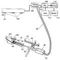
- FIGS. 1A and 1Billustrate an endoscope calibration apparatus constructed in accordance with the invention.
- An exemplary endoscope 8has an elongate shaft 16 defining a central axis 10 , and a distal lens 12 whose view vector, i.e., the direction of view, is aligned with axis 10 .
- the calibration procedureinvolves, in part, establishing a geometric relationship between a positional tracking assembly 14 attached to the endoscope, and shaft 16 and the tip 18 of the endoscope.
- a tracking system 20tracks the position and orientation of the tracking assembly only. Therefore, the relative position between tracking assembly 14 and the shaft and tip of the endoscope must be determined before use of the endoscope in order to (1) correctly select the position, orientation, and field-of-view (FOV) angle of the 3D volumetric perspective image to be displayed and (2) correctly fuse actual images obtained from the endoscope with 3D volumetric perspective images obtained from the pre-operative 2D scans.
- FOVfield-of-view
- FIGS. 1A and 1Bshow tracking assembly 14 attached to endoscope 8 .
- the assemblycan be attached by use of a detachable device such as a clip 22 .
- the assemblyis preferably attached to a proximal end 24 of endoscope 8 , e.g., to a handle 26 of the endoscope.
- the assemblyprovides at least three linear tracking elements 28 , such as light emitting diodes (LEDs), located at fixed linear positions on the assembly.
- the tracking elementsare arranged non-colinearly in a plane, as shown in FIGS. 1A and 1B. This arrangement is exemplary only.
- tracking assembliescapable of providing information relating to movement of a device having six degrees of freedom are suitable, so as to determine the three-dimensional coordinates of the device as well as the angle of attack ⁇ 2 and the angle of twist ⁇ of the attached endoscope (as described below).
- tracking elements 28emit continuous streams of pulsed infrared signals which are sensed by a plurality of infrared detectors 30 mounted in a sensing device 32 in view of endoscope 8 .
- the endoscope and the sensing deviceare both in communication with a tracking controller 31 which controls the timing and synchronization of the pulse emissions by the LEDs and the recording and processing of the infrared signals received by the detectors 30 .
- the tracking controlleris in communication with a CPU 34 which processes the digital signals received from the tracking controller.
- Tracking device 14 , sensing device 32 and tracking controller 31form part of an optical tracking system (OTS).
- OTSoptical tracking system
- the OTSmay be controlled by software which resides in memory 56 and is executed by the CPU for processing the incoming signals from the tracking controller to generate data and images indicating the location and orientation of the endoscope.
- the OTScan generate location and orientation data on a continuous, real-time basis, so that during calibration, as described herein, or as endoscope 8 is moved during surgery, its position and orientation are continually tracked by sensing device 32 and recorded in memory 56 .
- the OTSmay be of the type known as the “FlashPoint 3-D Optical Localizer,” which is commercially available from Image Guided Technologies of Boulder, Colo., similar to the systems described in U.S. Pat. Nos. 5,617,857 and 5,622,170.
- the inventionis not limited to any particular OTS; other position tracking systems, such as sonic position detecting systems, magnetic tracking systems, or radio transmitters, may also be utilized.
- FIGS. 1A and 1Bthere is also shown a holder 36 including a base plate 38 .
- the holderincludes positional elements 40 , which may be in the form of LEDs, mounted at known positions with respect to a guide 42 .
- the guidehas a channel 44 therethrough for slidably receiving the endoscope, as shown in FIG. 1 A.
- endoscope 8is held within guide 42 , as in FIG. 1B, a selected reference point on the endoscope is placed at a known position within guide 42 .
- the location of its tip 18becomes a known reference point.
- This positioncan be established, for example, by including a stop in the holder which arrests axial movement of the endoscope at a selected position, or by placing a ring or other stop member on the endoscope, to likewise arrest axial movement of the endoscope within the holder guide.
- the instrumentfit snugly in the guide so that the tip or other reference point on the instrument is fixed relative to positional elements 40 .
- the instrument tipis centered within the guide.
- the channelmay be of a dedicated-diameter in order to accommodate a specific instrument or type of instrument.
- the channel holdermay have a variable diameter that may be adjusted manually (e.g., with a screw, chuck or equivalent device) or automatically (e.g., with a motor-gear assembly).
- the channelmay be of a fixed diameter large enough to accommodate many different types of medical instruments which require calibration.
- a smaller-diameter instrumentmay be calibrated using a larger-diameter channel holder by employing a sheath or the like over the endoscope shaft.
- a sheathwould have an outer diameter just less than the diameter of the holder channel and an inner diameter just greater than the diameter of the endoscope shaft.
- the endoscope-sheath assemblyis inserted into guide 42 in the direction of arrow 48 and is snugly retained within the guide at an angle ⁇ 2 which has been predefined in relation to positional elements 40 .
- the angle of attack ⁇ 2is shown in FIG. 1C, in which endoscope 8 is represented by an arrow 50 within a coordinate system.
- the calibration procedureis initiated by user command which can be implemented by any convenient input device 54 such as a foot pedal, voice command, mouse, stylus, or keyboard.
- the endoscopeDuring calibration, the endoscope remains seated within guide 42 , during which time the LEDs 28 and 40 are tracked by detectors 30 mounted overhead on sensing device 32 in view of both positional elements 40 and tracking device 14 on the endoscope. These signals are then relayed to the tracking controller, which is in communication with sensing device 32 as shown in FIGS. 1 and 2, where the relative positions and orientations of tracking device 14 and positional elements 40 are determined. More specifically, the tracking controller or the CPU determines the relative positions and orientations of the tracking and positional elements 28 and 40 respectively, and determines from these relative positions, the positions of tracking elements 28 with respect to the reference point on endoscope 8 .
- the tracking system or CPUdetermines the position and orientation of tracking device 14 in relation to the position of tip 18 and the orientation of shaft 16 of the endoscope. These relationships are stored in memory 56 for later use during surgery.
- the geometric data relating the tracking device and the endoscopeis stored in computer memory 56 and remains invariant throughout the subsequent surgical procedure. If the same tracking device 14 is removed and placed on another medical instrument, then another calibration procedure is performed.
- Calibrating the medical instrumentnot only enables more accurate tracking of the instrument during a subsequent surgical procedure, but also improves a process of establishing the FOV angle ⁇ 1 of the endoscope lens 12 to enable accurate fusing during the surgical procedure of the endoscopic image with 3D perspective volumetric images constructed from preoperative or intraoperative scan data. In fusing these two types of images, it is important to use the same FOV angle by both the endoscope and the computer generated images so that the images can be registered together.
- holder 36includes a three-dimensional calibration pattern or object 60 —here a regular pyramid—supported on a stage 62 in the holder, for viewing by endoscope lens 12 when the endoscope is placed in holder 38 .
- the object or patternis positioned in a cavity formed at the base of the channel and is preferably centered so that it is aligned with central axis 10 of the inserted endoscope when it is inserted in channel 44 and aimed at the pattern whose position and orientation is precisely known in relation to positional elements 40 .
- the objectis a three-dimensional geometric object, such as a regular pyramid.
- the objectis a grid of raised objects. In either case, the endoscopic image of the object has three-dimensional of depth features.
- FIG. 2Ais a top view of a regular pyramid 60 supported on the stage 62 , as the object would be seen by the endoscope, when placed at a selected position within holder.
- the image as seen by the lenscalled the “video image” or “endoscope image” is shown at 60 a in FIG. 2 B.
- this video imageis displayed on one screen A of a two-screen display device, that is either a single split screen with split regions A and B, or two separate display screens A and B.
- a model image 65 a of the same objectis displayed on a second screen or screen portion B, and is a screen image of the same object as viewed through a lens with a known field of view, and at a known lens position with respect to the object, and known view vector (typically aligned the endoscope shaft).
- known view vectortypically aligned the endoscope shaft.
- These manipulationwill involve (i) translating one or both images, i.e., moving the images in a side-to-side (x) or up/down (y) direction; (ii) rotating one or both images about a fixed axis; and (iii) scaling one or both images, e.g., to expand or contract the images in either or both of the x and y directions.
- the extent of adjustments made to both images to bring them into alignmentis then used to determine appropriate transforms for position, rotation, and field-of-view transforms between the model image and video image, thus to determine the lens position and endoscope rotational position with respect to the tracking elements and the endoscope lens field of view, as will be described with reference to FIGS. 4 and 5.
- FIGS. 3A-3Eillustrate the types of image adjustments employed by the user to align a video image 60 a with a model image 65 a.
- the video imagesuch as shown in FIG. 3A
- the imageis moved by x,y adjustments toward the center of the screen, as in FIG. 3 B.
- the imageis then expanded to fill a large portion of the screen, indicated by the expanded image 60 a′ in FIG. 3 C.
- Screen B in FIG. 3Dshows a model image 65 a at the center of the screen, and at a given rotational position.
- the userrotates this image to a position like that of image 60 a′ in FIG. 3C, then expands the image to approximate the size of image 60 a , giving the rotated expanded image 65 a′ seen in FIG. 3 E.
- the two imageswhich are now roughly matched in x,y position, rotational position, and scale, are superimposed, allowing the user to make final position and scaling adjustments to bring the two images into alignment, as indicated in the figure.
- FIG. 4The image matching operations just described are shown in flow diagram form in FIG. 4 .
- the video imagecentered, as at 82 , by controlling x,y adjustments in screen (FIGS. 3 A and 3 B), then scaled to maximize the video field, as at 84 , and illustrated in FIG. 3 C.
- One of the two imagesin this case, the model image, is then rotated to match the other, as at 86 , scaled as at 88 to give the two images roughly the size, and translated, as at 90 , to place the two images in the center of the screen.
- the two imageswhich now have roughly the same screen position, size and orientation, are now superimposed, as at 92 , allowing further fine adjustment until the two images are precisely aligned.
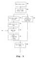
- FIG. 5illustrates steps in carrying out the calibration method, employing the apparatus of the invention.
- calibrationincluding determination of the FOV angle, are performed at the same time along with any other such pre-surgical instrument adjustment procedures, while the endoscope is retain in holder 36 .
- the positions of the tracking elements on the endoscope and the position elements on the holderare recorded by the sensing device and stored in the CPU (or processor), as at 68 .
- the endoscopecaptures an image of the pattern which is transmitted to the CPU through an appropriate video cable schematically shown in FIG. 1 A.
- This video imageis processed and displayed on a display screen 62 side-by-side with a computer-generated model of the same object or pattern, as described above, and indicated at 72 in FIG. 5 .
- the model imagesimulates a camera image in which optical properties, such as focal length, FOV angle, and distance to the pattern or object can be varied.
- the data for the computer-generated perspective modelis retrieved from computer memory 56 .
- An example of a suitable display deviceis a CRT monitor 64 , as shown in FIG. 1 A.
- the two imagesare adjusted, as at 74 , following the method described above and illustrated with respect to FIGS. 3 and 4. From these adjustments, the x,y position of the lens, the field of view, and optionally, lens distortion are calculated, as at 76 , for use by an image reconstruction system, as at 78 , for reconstructing images as would be seen by an endoscope having the calculated x,y coordinates and FOV angle.
- the positions of the tracking and position elements recorded by the sensing deviceare used to determine the z position of the endoscope lens (the position along the endoscope axis), as at 80 . From the amount of rotation needed to bring the video image into alignment with the model image, the rotational position of the endoscope of with respect to the tracking elements is also determined. The view vector, if it is not aligned with the endoscope shaft can also be determined with respect to the tracking elements.
- the systemnow know the endoscope lens coordinates, rotational position, and view vector with respect to the endoscope tracking elements, and the field of view of the endoscope lens.
- the systemcan reconstruct a virtual image, e.g., a subsurface image, as this would be seen by the endoscope, based on the known, calibrated lens coordinates, rotational position, view vector, and field of view of the endoscope.
- the image matchingcan be performed manually or can include automated procedures, as described with respect to the Second Apparatus and Method below.
- manual matching of the imagesinvolves changing the FOV angle of the simulated camera, such that the video appears the same size as the model image.
- Automatic matchinginvolves a calculation or counting by the CPU of the number of grids visible in image and a determination of the FOV angle based on the number of grids and the distance between the pattern and the endoscope. After the matching, the FOV angle of the 3D perspective image is determined and is stored in memory 56 , and is applied to all appropriate subsequently displayed 3D perspective images.
- the CPUis further operable, by user matching of the size and orientation of the two images, to correct for endoscope lens distortion effects, such that endoscope image displayed is a true perspective image. It is known, for example, that the images produced by all real lenses are spherically distorted due to the curved surface of the lens.
- the image 60 obtained by endoscopic lens 12may appear distorted in ways such as fish eye distortion or pincushion distortion.
- 3D perspective imagecan be modified morphed so that it matches distorted image 60 obtained by the endoscope 8 .
- 3D perspective imageis adjusted to match the video image produced by the endoscope.
- image 6 o produced by the endoscopecan itself be adjusted by image processing means known to those skilled in the art.
- the image obtained by the endoscopecan be adjusted to minimize or eliminate spherical distortion, e.g., to appear as seen in a Gaussian coordinate system (planar image), prior to matching with the 3D perspective image.
- the lens distortion correctionmay be performed by determining and recording the coordinates of each of the grid points in image 60 , and by iteratively minimizing a cost function for the updated distortion model.
- the cost functionmay be the root-mean-squared (RMS) value of the error between the recorded coordinates and predicted coordinates for the current distortion model.
- RMSroot-mean-squared
- a distortion modelmay include radial distortion, astigmatism distortion, angular distortion, etc.
- aspects of the inventionmay be implemented by a program of instructions (e.g., software) executed by CPU 34 .
- One such aspectincludes processing user input data and the data to determine the relative positions and orientations of the tracking and positional elements 28 and 40 respectively, and to determine from these relative positions, the positions of the tracking elements 28 with respect to the reference point (i.e., the tip 18 ) on the endoscope.
- Another aspect of the inventionwhich may be software-implemented is the processing of data to generate and render images in connection with the determination of the FOV angle ⁇ 1 and the distortion and offset compensation procedures.
- the software for such task(s)may be fetched for execution by the CPU from memory 56 which is in communication with the CPU and which may include random-access memory (RAM) and/or read-only memory (ROM).
- RAMrandom-access memory
- ROMread-only memory
- the softwaremay be conveyed to the memory, or alternatively may be transmitted directly to the CPU for execution, through an appropriate disk drive, modem or the like in communication with CPU 34 .
- the softwaremay be conveyed by any medium that is readable by the CPU.
- Such mediamay include, for example, various magnetic media such as disks or tapes, various optical media such as compact disks, as well as various communication paths throughout the electromagnetic spectrum including signals transmitted through a network or the internet including a carrier wave encoded to transmit the software.
- the above-described aspects of the inventionmay be implemented with functionally equivalent hardware using discrete components, application specific integrated circuits (ASICs), digital signal processing circuits, or the like.
- ASICsapplication specific integrated circuits
- Such hardwaremay be physically integrated with the CPU or may be a separate element which may be embodied on a computer card that can be inserted into an available card slot in the computer.
- FIG. 6shows an endoscope calibration apparatus constructed according to another general embodiment of the invention, for calibrating the lens position, orientation, field of view and optionally, lens distortion, of an endoscope 82 .
- endoscope 82includes an elongate shaft 84 terminating at a distal-end lens 86 which may be mounted for viewing along the endoscope shaft axis, or may have an angled view vector, e.g., angled 30° with respect to the shaft axis.
- the endoscopecan be calibrated without being physically connected to the holder when the view vector is aligned with the shaft axis.
- a handle 88 in the endoscopeis used to guide the scope, conventionally, and includes a control button (not shown) that the user activates to initiate a calibration operation, when the endoscope is placed on the apparatus or held by the user at a selected position with respect to the apparatus. This button connects to control elements of the apparatus as shown.
- the endoscopeincludes a tracking assembly 90 having four tracking elements, such as elements 95 , for tracking the position of the endoscope in the coordinate system of the surgical environment, as described above. As above, at least three-non-linear tracking elements are required.
- Apparatus 80includes, in addition to the just-mentioned endoscope tracking assembly, a holder 94 which provides a cradle 96 in which the shaft of the endoscope can be placed, for holding the shaft at a known orientation with respect to the holder, and a feature pattern 98 which is the calibration pattern used in the method, similar to the three-dimensional object employed in the first embodiment.
- a holder 94which provides a cradle 96 in which the shaft of the endoscope can be placed, for holding the shaft at a known orientation with respect to the holder
- a feature pattern 98which is the calibration pattern used in the method, similar to the three-dimensional object employed in the first embodiment.
- the patternpreferably has an array of features, such as a pattern of dots or different sizes, that allows any region of the pattern to be uniquely identified by the pattern in that region, and (ii) the pattern is viewed by the endoscope lens so as to provide pattern depth information.
- thismay be accomplished by viewing a planar pattern (FIGS. 7A and 7B) at an angle, or by viewing a pattern formed on a curved surface, such as a hemispherical shell (FIGS. 8 A and 8 B).
- Holder 94is also provided with a tracking assembly 100 having four positional elements, such as elements 102 , for tracking the position of the holder in the coordinate system of the surgical environment, also as described above.
- the positions of the holder and endoscopeare tracked, during an endoscope-calibration operation, by sensing device 104 which is secured at a fixed position suitable for receiving signals form or emitting signals to the two tracking assemblies, as described for the first embodiment of the invention.
- the sensing deviceis operably connected to a tacking controller 106 which in turn is operably connected to a processor 106 having a CPU 108 and memory 108 , and connected to a display device or monitor 114 , and receiving selected user inputs from input devices 112 .
- the operational features of the processor, in carrying out the calibration method of the inventionwill be apparent from the method operation described below.
- FIG. 7Ashows a planar feature pattern 120 suitable for use in the invention, and supported on a planar surface in a holder of the type described above.
- the patternis carried on a planar surface at an angle preferably at least about 30° from the axis of the endoscope's view vector, when the endoscope shaft is placed in the holder cradle.
- the axis of the handlemakes an angle of at least about 30° with a line normal to the pattern surface.
- the patternis composed of an array of relatively small dots or spots 122 , and relatively large dots 124 , it being recognized that the two classes of dots may be characterized by different sizes (as shown), different colors, or different shapes.
- FIG. 7Bshows the same pattern 120 a of large and small dots 124 a , 122 a , respectively, as seen through an endoscope lens, e.g., when an endoscope is cradled in the holder and the view vector is aligned with the endoscope shaft.
- the pattern of small and large dotsallows each the particular region being viewed, and each pattern spot being viewed, to be identified with a particular dot in the planar pattern.
- the spacing between adjacent dotsprovides both pattern-depth and lens distortion information, as will be seen.
- FIG. 8Ashows a feature pattern 130 formed on the interior of a hemispherical shell 132 in a holder.
- the patternconsists of large and small dots, such as dots 134 , 136 , having a unique arrangement of the two different sized dots in each region of the pattern.
- the correspondence between each dot in the pattern and dot spot in the imagecan be readily determined, and thus the distance relationships between and among dots in the image, as seen through the endoscope lens, and also as affected by lens distortion, can be readily quantitated.
- FIG. 9is a flow diagram of the steps in the method of the invention, as carried out by the user and processor in the apparatus.
- the userplaces the endoscope at a selected position with respect to the holder, as at 150 , for endoscope viewing of the feature pattern in the holder.
- the view vectoris aligned with the endoscope shaft, it is not necessary to place the endoscope shaft in the cradle of the holder, only to place the endoscope for viewing the holder pattern at a position which provides depth information.
- the endoscopeshould be positioned at an angle of at least 30° with respect to a line normal to the pattern plane; for a pattern formed on a curved surface, a variety of view angles may be selected.
- the endoscope shaftshould be placed in the holder cradle, to provide a known endoscope shaft orientation.
- the usersignals the apparatus to record the positions of the endoscope tracker elements and holder positional elements, as at 152 , and at the same time, record the endoscope image at the recorded position, as at 154 .
- the video image producedsuch as indicated in FIGS. 7A and 8B, may be automatically enhanced by the processor, as at 156 , and the processor than records the size (feature detection) and x,y coordinates of each of the dots in the image, as at 158 .
- the signalingmay also be designed to occur when the endoscope and holder are held at fixed calibration position for some given period of time.
- the video imageis processed, by a processor camera-calibration algorithm indicated at 160 , to determine (i) the x,y,z coordinates of the endoscope lens and the orientation of the endoscope view vector with respect to the endoscope tracking elements, and (ii) the field of view and optionally, lens distortion in the endoscope lens.
- the algorithm usedis a so-called camera-calibration algorithm, such as the one reported by Tsai (Tsai).
- the input parameters to the algorithmare the world coordinates (x, y, z) of a set of known points and their corresponding u, v coordinates in the endoscope video image.
- the featuresare identified in the camera image and mapped to the reference pattern; in this way, the real-world coordinates of the features can be found.
- the best resultsare obtained when the collection of points are distributed across x, y, and z in world coordinates, and fill as much of the camera image as possible.
- the world coordinates of the dotsare defined with respect to a tracking tool rigidly attached to the calibration unit.
- the endoscope, equipped with the universal tracker,is then placed into the holder with its lens a selected distance, e.g., 15 mm, from the center of the pattern.
- the telescope lens view directionis constrained to an angle of 30° from the normal of the pattern plane.
- the algorithmfirst calculates a number of camera parameters in the camera coordinate system, as at 160 .
- the lens coordinates and viewing directionare then placed in the coordinate system of the tracking system, as at 162 .
- the angle of the viewing vector with the pattern normalis calculated, and if less than 30°, (for a planar pattern) the user the user may have the choice of a second recording to achieve a more accurate and reliable calibration.
- the calibration information from the systemis then supplied to the image system for use in an image-guided endoscopic procedure that allows 3-D image reconstruction from the position and FOV of the endoscope.
- lens distortion parameter ⁇ 1a coefficient of the cubic radial lens distortion model. Incorporating this nonlinear model into the 3D perspective rendering engine results in a drop in performance; if this lens distortion compensation is omitted, a choice has to be made about the effective FOV of the virtual endoscope. If this FOV is set to match that of the physical endoscope, the result is that the center part of the virtual image is smaller than that in the video image. This effect is undesirable because this is the primary region of interest for the surgeon.
- An alternative method, here named “constant-radius linear compensation”is to scale the virtual FOV such that the radii of the region of interest in each image are made equal.
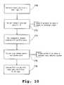
- FIG. 10is a flow chart showing steps in the linear compensation method.
- the userfinds a point P 1 closest to the center of the image, as at 170 , then selects a circle within the image field that represents the image area of main interest for the endoscopic images, as at 172 , and a second point P 2 closest to the edge of the circle. For example, one may locate a point P 2 whose distance from P 1 is about half the total radius of the image.
- the calibration algorithmis used to calculate the physical position of the camera, and from this the angle between the camera and the two selected physical points, as at 176 .
- the endoscopic field of viewis then calculated as the ratio of the full image radius/R times twice the calculated angle, as at 178 .
- the initially calculated FOVis 60°
- the radius of the full imageis 10 inches
- that of the condensed image5 inches
- the FOV between points P 1 and P 2is 12°.
- the corrected or compensated FOVis thus 10/5 times 24°, or 48°.
- an endoscopeis readily calibrated so that (i) its position is space, as determined by tracking elements, can be accurately correlated with the three-dimensional coordinates of the lens, the view angle and twist of the endoscope, and the lens' FOV.
- Thisallows a physician, using a 3-D image reconstruction system of the type described, to view reconstructed surface of subsurface images as these would be seen by the endoscope, with the endoscope positioned and oriented at a desired view location, either outside the body or within a body orifice.
- the separate endoscopic and virtual imagescan be superimposed or viewed side-by-side, allowing the user to use virtual surface images to augment or replace endoscopic images, when the endoscope lens is clouded or blocked, and to “see beyond” an actual endoscopic view with subsurface views, e.g., perspective views as would be seen by the endoscope through x-ray vision. Further, both embodiments allow for lens distortion correction, to more accurately fit endoscopic and virtual views, particularly at the center region of the field of view.
- the second embodimentprovides several unique advantages which facilitate and speed up the calibration process.
- the methodis rapid and requires little of no user input, e.g., for image matching, in order to determine all six lens coordinates, view vector, FOV, and lens distortion effects.
- the endoscopedoes not have to be placed in a holder, e.g., holder cavity or cradle, that constrains two of its rotational coordinates (if the endoscope view vector is aligned with the shaft axis) or to be placed against a spot in the holder that constrains its z position.
- a holdere.g., holder cavity or cradle
- the usercan simply hold the endoscope in one hand, the holder in the other, and bring the two into a desired view relationship, for initiating the calibration process.
- Correcting for lens distortion effects, particularly in the central region of the imageis readily accomplished by using FOV adjustments from the algorithm at full view and a reduced-field view.
Landscapes
- Health & Medical Sciences (AREA)
- Life Sciences & Earth Sciences (AREA)
- Surgery (AREA)
- Engineering & Computer Science (AREA)
- Animal Behavior & Ethology (AREA)
- Public Health (AREA)
- Nuclear Medicine, Radiotherapy & Molecular Imaging (AREA)
- Veterinary Medicine (AREA)
- General Health & Medical Sciences (AREA)
- Molecular Biology (AREA)
- Medical Informatics (AREA)
- Biomedical Technology (AREA)
- Heart & Thoracic Surgery (AREA)
- Pathology (AREA)
- Physics & Mathematics (AREA)
- Radiology & Medical Imaging (AREA)
- Biophysics (AREA)
- Optics & Photonics (AREA)
- Signal Processing (AREA)
- Robotics (AREA)
- Oral & Maxillofacial Surgery (AREA)
- Endoscopes (AREA)
- Instruments For Viewing The Inside Of Hollow Bodies (AREA)
Abstract
Description
Claims (9)
Priority Applications (1)
| Application Number | Priority Date | Filing Date | Title |
|---|---|---|---|
| US09/821,916US6517478B2 (en) | 2000-03-30 | 2001-03-30 | Apparatus and method for calibrating an endoscope |
Applications Claiming Priority (2)
| Application Number | Priority Date | Filing Date | Title |
|---|---|---|---|
| US19320900P | 2000-03-30 | 2000-03-30 | |
| US09/821,916US6517478B2 (en) | 2000-03-30 | 2001-03-30 | Apparatus and method for calibrating an endoscope |
Publications (2)
| Publication Number | Publication Date |
|---|---|
| US20010051761A1 US20010051761A1 (en) | 2001-12-13 |
| US6517478B2true US6517478B2 (en) | 2003-02-11 |
Family
ID=26888780
Family Applications (1)
| Application Number | Title | Priority Date | Filing Date |
|---|---|---|---|
| US09/821,916Expired - LifetimeUS6517478B2 (en) | 2000-03-30 | 2001-03-30 | Apparatus and method for calibrating an endoscope |
Country Status (1)
| Country | Link |
|---|---|
| US (1) | US6517478B2 (en) |
Cited By (66)
| Publication number | Priority date | Publication date | Assignee | Title |
|---|---|---|---|---|
| US20020077544A1 (en)* | 2000-09-23 | 2002-06-20 | Ramin Shahidi | Endoscopic targeting method and system |
| US20020183590A1 (en)* | 2001-05-30 | 2002-12-05 | Olympus Optical Co., Ltd. | Measuring endoscope apparatus |
| US20030060681A1 (en)* | 2001-08-31 | 2003-03-27 | Olympus Optical Co., Ltd. | Instrumentation endoscope apparatus |
| US20030125717A1 (en)* | 2001-12-04 | 2003-07-03 | Whitman Michael P. | System and method for calibrating a surgical instrument |
| US20030209096A1 (en)* | 2001-01-30 | 2003-11-13 | Z-Kat, Inc. | Tool calibrator and tracker system |
| US20040034300A1 (en)* | 2002-08-19 | 2004-02-19 | Laurent Verard | Method and apparatus for virtual endoscopy |
| US20050131426A1 (en)* | 2003-12-10 | 2005-06-16 | Moctezuma De La Barrera Jose L. | Adapter for surgical navigation trackers |
| US20050261551A1 (en)* | 2004-05-18 | 2005-11-24 | Scimed Life Systems, Inc. | Serialization of single use endoscopes |
| US20070100325A1 (en)* | 2005-11-03 | 2007-05-03 | Sebastien Jutras | Multifaceted tracker device for computer-assisted surgery |
| US20070135789A1 (en)* | 2004-04-21 | 2007-06-14 | Acclarent, Inc. | Use of mechanical dilator devices to enlarge ostia of paranasal sinuses and other passages in the ear, nose, throat and paranasal sinuses |
| US20070142707A1 (en)* | 2005-12-15 | 2007-06-21 | Microvision, Inc. | Method and apparatus for calibrating an endoscope system |
| US20080076965A1 (en)* | 2005-03-09 | 2008-03-27 | Fukashi Yoshizawa | Body-Insertable Apparatus and Body-Insertable Apparatus System |
| US20080097156A1 (en)* | 2006-10-23 | 2008-04-24 | Pentax Corporation | Camera calibration for endoscope navigation system |
| US20080204000A1 (en)* | 2007-02-26 | 2008-08-28 | General Electric Company | Universal instrument calibration system and method of use |
| US20090005763A1 (en)* | 2004-08-04 | 2009-01-01 | Exploramed Nc1, Inc. | Implantable Devices and Methods for Delivering Drugs and Other Substances to Treat Sinusitis and Other Disorders |
| US20090088630A1 (en)* | 2003-12-10 | 2009-04-02 | Skryker Leibinger Gmbh & Co., Kg | Surgical navigation tracker, system and method |
| US20090154293A1 (en)* | 2007-12-18 | 2009-06-18 | Anandraj Sengupta | System and method for augmented reality inspection and data visualization |
| US20100217075A1 (en)* | 2007-12-28 | 2010-08-26 | Olympus Medical Systems Corp. | Medical apparatus system |
| US8052598B2 (en) | 2006-10-12 | 2011-11-08 | General Electric Company | Systems and methods for calibrating an endoscope |
| US8080000B2 (en) | 2004-04-21 | 2011-12-20 | Acclarent, Inc. | Methods and apparatus for treating disorders of the ear nose and throat |
| US8088101B2 (en) | 2004-04-21 | 2012-01-03 | Acclarent, Inc. | Devices, systems and methods for treating disorders of the ear, nose and throat |
| US8100933B2 (en) | 2002-09-30 | 2012-01-24 | Acclarent, Inc. | Method for treating obstructed paranasal frontal sinuses |
| US8114113B2 (en) | 2005-09-23 | 2012-02-14 | Acclarent, Inc. | Multi-conduit balloon catheter |
| US8114062B2 (en) | 2004-04-21 | 2012-02-14 | Acclarent, Inc. | Devices and methods for delivering therapeutic substances for the treatment of sinusitis and other disorders |
| US8118757B2 (en) | 2007-04-30 | 2012-02-21 | Acclarent, Inc. | Methods and devices for ostium measurement |
| US8142422B2 (en) | 2004-04-21 | 2012-03-27 | Acclarent, Inc. | Devices, systems and methods for diagnosing and treating sinusitis and other disorders of the ears, nose and/or throat |
| US8146400B2 (en) | 2004-04-21 | 2012-04-03 | Acclarent, Inc. | Endoscopic methods and devices for transnasal procedures |
| DE102010042540A1 (en)* | 2010-10-15 | 2012-04-19 | Scopis Gmbh | Method and apparatus for calibrating an optical system, distance determining device and optical system |
| US8172828B2 (en) | 2004-04-21 | 2012-05-08 | Acclarent, Inc. | Apparatus and methods for dilating and modifying ostia of paranasal sinuses and other intranasal or paranasal structures |
| US8182432B2 (en) | 2008-03-10 | 2012-05-22 | Acclarent, Inc. | Corewire design and construction for medical devices |
| US8190389B2 (en)* | 2006-05-17 | 2012-05-29 | Acclarent, Inc. | Adapter for attaching electromagnetic image guidance components to a medical device |
| US8388642B2 (en) | 2005-01-18 | 2013-03-05 | Acclarent, Inc. | Implantable devices and methods for treating sinusitis and other disorders |
| US8414473B2 (en) | 2004-04-21 | 2013-04-09 | Acclarent, Inc. | Methods and apparatus for treating disorders of the ear nose and throat |
| US8435290B2 (en) | 2009-03-31 | 2013-05-07 | Acclarent, Inc. | System and method for treatment of non-ventilating middle ear by providing a gas pathway through the nasopharynx |
| US8439687B1 (en) | 2006-12-29 | 2013-05-14 | Acclarent, Inc. | Apparatus and method for simulated insertion and positioning of guidewares and other interventional devices |
| US8485199B2 (en) | 2007-05-08 | 2013-07-16 | Acclarent, Inc. | Methods and devices for protecting nasal turbinate during surgery |
| US8702626B1 (en) | 2004-04-21 | 2014-04-22 | Acclarent, Inc. | Guidewires for performing image guided procedures |
| US8740929B2 (en) | 2001-02-06 | 2014-06-03 | Acclarent, Inc. | Spacing device for releasing active substances in the paranasal sinus |
| US8747389B2 (en) | 2004-04-21 | 2014-06-10 | Acclarent, Inc. | Systems for treating disorders of the ear, nose and throat |
| US8764729B2 (en) | 2004-04-21 | 2014-07-01 | Acclarent, Inc. | Frontal sinus spacer |
| US8864787B2 (en) | 2004-04-21 | 2014-10-21 | Acclarent, Inc. | Ethmoidotomy system and implantable spacer devices having therapeutic substance delivery capability for treatment of paranasal sinusitis |
| US8894614B2 (en) | 2004-04-21 | 2014-11-25 | Acclarent, Inc. | Devices, systems and methods useable for treating frontal sinusitis |
| US8932276B1 (en) | 2004-04-21 | 2015-01-13 | Acclarent, Inc. | Shapeable guide catheters and related methods |
| US8951225B2 (en) | 2005-06-10 | 2015-02-10 | Acclarent, Inc. | Catheters with non-removable guide members useable for treatment of sinusitis |
| US8979888B2 (en) | 2008-07-30 | 2015-03-17 | Acclarent, Inc. | Paranasal ostium finder devices and methods |
| US9072626B2 (en) | 2009-03-31 | 2015-07-07 | Acclarent, Inc. | System and method for treatment of non-ventilating middle ear by providing a gas pathway through the nasopharynx |
| US9089258B2 (en) | 2004-04-21 | 2015-07-28 | Acclarent, Inc. | Endoscopic methods and devices for transnasal procedures |
| US9101384B2 (en) | 2004-04-21 | 2015-08-11 | Acclarent, Inc. | Devices, systems and methods for diagnosing and treating sinusitis and other disorders of the ears, Nose and/or throat |
| US9107574B2 (en) | 2004-04-21 | 2015-08-18 | Acclarent, Inc. | Endoscopic methods and devices for transnasal procedures |
| US9155492B2 (en) | 2010-09-24 | 2015-10-13 | Acclarent, Inc. | Sinus illumination lightwire device |
| US9265407B2 (en) | 2004-04-21 | 2016-02-23 | Acclarent, Inc. | Endoscopic methods and devices for transnasal procedures |
| US9351750B2 (en) | 2004-04-21 | 2016-05-31 | Acclarent, Inc. | Devices and methods for treating maxillary sinus disease |
| US9399121B2 (en) | 2004-04-21 | 2016-07-26 | Acclarent, Inc. | Systems and methods for transnasal dilation of passageways in the ear, nose or throat |
| US9433437B2 (en) | 2013-03-15 | 2016-09-06 | Acclarent, Inc. | Apparatus and method for treatment of ethmoid sinusitis |
| US9468362B2 (en) | 2004-04-21 | 2016-10-18 | Acclarent, Inc. | Endoscopic methods and devices for transnasal procedures |
| US9629684B2 (en) | 2013-03-15 | 2017-04-25 | Acclarent, Inc. | Apparatus and method for treatment of ethmoid sinusitis |
| US9820688B2 (en) | 2006-09-15 | 2017-11-21 | Acclarent, Inc. | Sinus illumination lightwire device |
| US9913573B2 (en) | 2003-04-01 | 2018-03-13 | Boston Scientific Scimed, Inc. | Endoscopic imaging system |
| US20180161090A1 (en)* | 2016-12-12 | 2018-06-14 | Amandeep Singh Pabla | Navigated bipolar forceps |
| US10188413B1 (en) | 2004-04-21 | 2019-01-29 | Acclarent, Inc. | Deflectable guide catheters and related methods |
| US10206821B2 (en) | 2007-12-20 | 2019-02-19 | Acclarent, Inc. | Eustachian tube dilation balloon with ventilation path |
| US10223589B2 (en) | 2015-03-03 | 2019-03-05 | Cognex Corporation | Vision system for training an assembly system through virtual assembly of objects |
| US10524814B2 (en) | 2009-03-20 | 2020-01-07 | Acclarent, Inc. | Guide system with suction |
| US11065061B2 (en) | 2004-04-21 | 2021-07-20 | Acclarent, Inc. | Systems and methods for performing image guided procedures within the ear, nose, throat and paranasal sinuses |
| US11529502B2 (en) | 2004-04-21 | 2022-12-20 | Acclarent, Inc. | Apparatus and methods for dilating and modifying ostia of paranasal sinuses and other intranasal or paranasal structures |
| US11690680B2 (en) | 2019-03-19 | 2023-07-04 | Mako Surgical Corp. | Trackable protective packaging for tools and methods for calibrating tool installation using the same |
Families Citing this family (35)
| Publication number | Priority date | Publication date | Assignee | Title |
|---|---|---|---|---|
| JP4800591B2 (en)* | 2004-05-26 | 2011-10-26 | オリンパス株式会社 | Shooting system |
| US9002432B2 (en)* | 2004-11-15 | 2015-04-07 | Brainlab Ag | Method and device for calibrating a medical instrument |
| EP1667067B1 (en)* | 2004-11-15 | 2008-10-01 | BrainLAB AG | Method and apparatus for calibrating a medical instrument |
| US7680373B2 (en) | 2006-09-13 | 2010-03-16 | University Of Washington | Temperature adjustment in scanning beam devices |
| US7738762B2 (en) | 2006-12-15 | 2010-06-15 | University Of Washington | Attaching optical fibers to actuator tubes with beads acting as spacers and adhesives |
| US7447415B2 (en) | 2006-12-15 | 2008-11-04 | University Of Washington | Attaching optical fibers to actuator tubes with beads acting as spacers and adhesives |
| US8305432B2 (en) | 2007-01-10 | 2012-11-06 | University Of Washington | Scanning beam device calibration |
| US7583872B2 (en) | 2007-04-05 | 2009-09-01 | University Of Washington | Compact scanning fiber device |
| US7608842B2 (en) | 2007-04-26 | 2009-10-27 | University Of Washington | Driving scanning fiber devices with variable frequency drive signals |
| US8212884B2 (en) | 2007-05-22 | 2012-07-03 | University Of Washington | Scanning beam device having different image acquisition modes |
| US7522813B1 (en) | 2007-10-04 | 2009-04-21 | University Of Washington | Reducing distortion in scanning fiber devices |
| US7995798B2 (en)* | 2007-10-15 | 2011-08-09 | Given Imaging Ltd. | Device, system and method for estimating the size of an object in a body lumen |
| US8411922B2 (en) | 2007-11-30 | 2013-04-02 | University Of Washington | Reducing noise in images acquired with a scanning beam device |
| US20090177042A1 (en)* | 2008-01-09 | 2009-07-09 | University Of Washington | Color image acquisition with scanning laser beam devices |
| US8382657B1 (en)* | 2009-10-05 | 2013-02-26 | Integrated Medical Systems International, Inc | Endoscope testing device and method of using same |
| DE102011078212B4 (en) | 2011-06-28 | 2017-06-29 | Scopis Gmbh | Method and device for displaying an object |
| US9351782B2 (en)* | 2012-11-09 | 2016-05-31 | Orthosensor Inc. | Medical device motion and orientation tracking system |
| US9723972B2 (en) | 2013-03-04 | 2017-08-08 | Boston Scientific Scimed, Inc. | Methods and apparatus for calibration of a sensor associated with an endoscope |
| US20150097968A1 (en)* | 2013-10-09 | 2015-04-09 | United Sciences, Llc. | Integrated calibration cradle |
| JP5889495B2 (en)* | 2014-02-14 | 2016-03-22 | オリンパス株式会社 | Endoscope system |
| EP3122232B1 (en)* | 2014-03-28 | 2020-10-21 | Intuitive Surgical Operations Inc. | Alignment of q3d models with 3d images |
| WO2015149043A1 (en) | 2014-03-28 | 2015-10-01 | Dorin Panescu | Quantitative three-dimensional imaging and printing of surgical implants |
| KR102373714B1 (en) | 2014-03-28 | 2022-03-15 | 인튜어티브 서지컬 오퍼레이션즈 인코포레이티드 | Quantitative three-dimensional imaging of surgical scenes from multiport perspectives |
| WO2015149044A1 (en) | 2014-03-28 | 2015-10-01 | Dorin Panescu | Surgical system with haptic feedback based upon quantitative three-dimensional imaging |
| WO2015149040A1 (en) | 2014-03-28 | 2015-10-01 | Dorin Panescu | Quantitative three-dimensional imaging of surgical scenes |
| CN106456267B (en) | 2014-03-28 | 2020-04-03 | 直观外科手术操作公司 | Quantitative 3D visualization of instruments in the field of view |
| DE102014206289A1 (en)* | 2014-04-02 | 2015-10-08 | Robert Bosch Gmbh | Hand tool system, method of operation |
| USD820983S1 (en)* | 2016-12-22 | 2018-06-19 | Leila KHERADPIR | Calibration apparatus |
| WO2018125218A1 (en)* | 2016-12-30 | 2018-07-05 | Barco Nv | System and method for camera calibration |
| US11344180B2 (en) | 2017-06-15 | 2022-05-31 | Children's National Medical Center | System, apparatus, and method for calibrating oblique-viewing rigid endoscope |
| US11298001B2 (en)* | 2018-03-29 | 2022-04-12 | Canon U.S.A., Inc. | Calibration tool for rotating endoscope |
| CN111759462B (en)* | 2020-07-31 | 2024-11-15 | 北京柏惠维康科技股份有限公司 | Calibration device, system, method and storage medium |
| US20230329789A1 (en)* | 2022-04-18 | 2023-10-19 | Ix Innovation Llc | Apparatus, system, and method for implanting surgical material |
| CN115299843B (en)* | 2022-06-17 | 2023-04-07 | 中山市微视医用科技有限公司 | Endoscope lens flatness adjusting system and using method thereof |
| CN115252129A (en)* | 2022-08-10 | 2022-11-01 | 上海微创微航机器人有限公司 | Instrument pose control method and device, computer equipment and storage medium |
Citations (5)
| Publication number | Priority date | Publication date | Assignee | Title |
|---|---|---|---|---|
| US5704897A (en)* | 1992-07-31 | 1998-01-06 | Truppe; Michael J. | Apparatus and method for registration of points of a data field with respective points of an optical image |
| US5820547A (en)* | 1996-09-25 | 1998-10-13 | Karl Storz Gmbh & Co. | Endoscope optics tester |
| US6081336A (en)* | 1997-09-26 | 2000-06-27 | Picker International, Inc. | Microscope calibrator |
| US6306126B1 (en)* | 1998-09-18 | 2001-10-23 | Stryker Leibinger Gmbh & Co Kg | Calibrating device |
| US6388742B1 (en)* | 2000-05-03 | 2002-05-14 | Karl Storz Endovision | Method and apparatus for evaluating the performance characteristics of endoscopes |
- 2001
- 2001-03-30USUS09/821,916patent/US6517478B2/ennot_activeExpired - Lifetime
Patent Citations (5)
| Publication number | Priority date | Publication date | Assignee | Title |
|---|---|---|---|---|
| US5704897A (en)* | 1992-07-31 | 1998-01-06 | Truppe; Michael J. | Apparatus and method for registration of points of a data field with respective points of an optical image |
| US5820547A (en)* | 1996-09-25 | 1998-10-13 | Karl Storz Gmbh & Co. | Endoscope optics tester |
| US6081336A (en)* | 1997-09-26 | 2000-06-27 | Picker International, Inc. | Microscope calibrator |
| US6306126B1 (en)* | 1998-09-18 | 2001-10-23 | Stryker Leibinger Gmbh & Co Kg | Calibrating device |
| US6388742B1 (en)* | 2000-05-03 | 2002-05-14 | Karl Storz Endovision | Method and apparatus for evaluating the performance characteristics of endoscopes |
Non-Patent Citations (8)
| Title |
|---|
| Asari, K.V. et al., "Technique of distortion correction in endoscopic images using a polynomial expansion", Med. Biol. Comput., 37:8-12, 1999. |
| Khadem, R. et al., "Comparative Tracking Error Analysis of Five Different Optical Tracking Systems", Computer Aided Surgery, 5:98-107, 2000. |
| Krotkov, E., et al., "Stereo Ranging with Verging Cameras", IEEE Transactions on Pattern Analysis and Machine Intelligence, 12(12):1200-1205, 1990. |
| Shahidi, R., "Applications on virtual reality in stereotactic procedures: volumetric image navigation via a surgical microscope", Ph.D. Dissertation, Rutgers University, Rutgers, NJ, abstract only, 1995. |
| Tsai, R.Y., "An Efficient and Accurate Camera Calibration Technique for 3D Machine Vision", Proceedings of IEEE Conference on Computer Vision and Pattern Recognition, pp. 364-374, 1986. |
| Viergever, M.A. (ed.), "Image Guidance of Therapy", IEEE Transactions on Midical Image, 17(5):669-685, 1998. |
| Vining, D. J., "Virtual Endoscopy: Is It Reality?", Radiology, 200:30-31, 1996. |
| Weng, J. et al., "Camera Calibration with Distortion Models and Accuracy Evaluation", IEEE Transactions on Pattern Analysis and Machine Intelligence, 14(10):965-980, 1992. |
Cited By (173)
| Publication number | Priority date | Publication date | Assignee | Title |
|---|---|---|---|---|
| US20020077544A1 (en)* | 2000-09-23 | 2002-06-20 | Ramin Shahidi | Endoscopic targeting method and system |
| US6850794B2 (en)* | 2000-09-23 | 2005-02-01 | The Trustees Of The Leland Stanford Junior University | Endoscopic targeting method and system |
| US20030209096A1 (en)* | 2001-01-30 | 2003-11-13 | Z-Kat, Inc. | Tool calibrator and tracker system |
| US7043961B2 (en)* | 2001-01-30 | 2006-05-16 | Z-Kat, Inc. | Tool calibrator and tracker system |
| US8740929B2 (en) | 2001-02-06 | 2014-06-03 | Acclarent, Inc. | Spacing device for releasing active substances in the paranasal sinus |
| US6890296B2 (en)* | 2001-05-30 | 2005-05-10 | Olympus Corporation | Measuring endoscope apparatus |
| US20020183590A1 (en)* | 2001-05-30 | 2002-12-05 | Olympus Optical Co., Ltd. | Measuring endoscope apparatus |
| US6945930B2 (en)* | 2001-08-31 | 2005-09-20 | Olympus Corporation | Environment adaptable measurement endoscope |
| US20030060681A1 (en)* | 2001-08-31 | 2003-03-27 | Olympus Optical Co., Ltd. | Instrumentation endoscope apparatus |
| US20100324541A1 (en)* | 2001-12-04 | 2010-12-23 | Power Medical Interventions, Llc | System and method for calibrating a surgical instrument |
| US20030125717A1 (en)* | 2001-12-04 | 2003-07-03 | Whitman Michael P. | System and method for calibrating a surgical instrument |
| US7803151B2 (en)* | 2001-12-04 | 2010-09-28 | Power Medical Interventions, Llc | System and method for calibrating a surgical instrument |
| US10758225B2 (en) | 2001-12-04 | 2020-09-01 | Covidien Lp | System and method for calibrating a surgical instrument |
| US9743927B2 (en) | 2001-12-04 | 2017-08-29 | Covidien Lp | System and method for calibrating a surgical instrument |
| US6892090B2 (en) | 2002-08-19 | 2005-05-10 | Surgical Navigation Technologies, Inc. | Method and apparatus for virtual endoscopy |
| US20040034300A1 (en)* | 2002-08-19 | 2004-02-19 | Laurent Verard | Method and apparatus for virtual endoscopy |
| US20050143651A1 (en)* | 2002-08-19 | 2005-06-30 | Laurent Verard | Method and apparatus for virtual endoscopy |
| US9457175B2 (en) | 2002-09-30 | 2016-10-04 | Acclarent, Inc. | Balloon catheters and methods for treating paranasal sinuses |
| US8764786B2 (en) | 2002-09-30 | 2014-07-01 | Acclarent, Inc. | Balloon catheters and methods for treating paranasal sinuses |
| US8317816B2 (en) | 2002-09-30 | 2012-11-27 | Acclarent, Inc. | Balloon catheters and methods for treating paranasal sinuses |
| US8100933B2 (en) | 2002-09-30 | 2012-01-24 | Acclarent, Inc. | Method for treating obstructed paranasal frontal sinuses |
| US11324395B2 (en) | 2003-04-01 | 2022-05-10 | Boston Scientific Scimed, Inc. | Endoscopic imaging system |
| US9913573B2 (en) | 2003-04-01 | 2018-03-13 | Boston Scientific Scimed, Inc. | Endoscopic imaging system |
| US10765307B2 (en) | 2003-04-01 | 2020-09-08 | Boston Scientific Scimed, Inc. | Endoscopic imaging system |
| US20050131426A1 (en)* | 2003-12-10 | 2005-06-16 | Moctezuma De La Barrera Jose L. | Adapter for surgical navigation trackers |
| US7873400B2 (en)* | 2003-12-10 | 2011-01-18 | Stryker Leibinger Gmbh & Co. Kg. | Adapter for surgical navigation trackers |
| US20090088630A1 (en)* | 2003-12-10 | 2009-04-02 | Skryker Leibinger Gmbh & Co., Kg | Surgical navigation tracker, system and method |
| US7771436B2 (en) | 2003-12-10 | 2010-08-10 | Stryker Leibinger Gmbh & Co. Kg. | Surgical navigation tracker, system and method |
| US10098652B2 (en) | 2004-04-21 | 2018-10-16 | Acclarent, Inc. | Systems and methods for transnasal dilation of passageways in the ear, nose or throat |
| US9167961B2 (en) | 2004-04-21 | 2015-10-27 | Acclarent, Inc. | Methods and apparatus for treating disorders of the ear nose and throat |
| US11957318B2 (en) | 2004-04-21 | 2024-04-16 | Acclarent, Inc. | Methods and apparatus for treating disorders of the ear nose and throat |
| US11864725B2 (en) | 2004-04-21 | 2024-01-09 | Acclarent, Inc. | Devices, systems and methods for diagnosing and treating sinusitis and other disorders of the ears, nose and/or throat |
| US11589742B2 (en) | 2004-04-21 | 2023-02-28 | Acclarent, Inc. | Methods and apparatus for treating disorders of the ear nose and throat |
| US11529502B2 (en) | 2004-04-21 | 2022-12-20 | Acclarent, Inc. | Apparatus and methods for dilating and modifying ostia of paranasal sinuses and other intranasal or paranasal structures |
| US11511090B2 (en) | 2004-04-21 | 2022-11-29 | Acclarent, Inc. | Devices, systems and methods useable for treating sinusitis |
| US8080000B2 (en) | 2004-04-21 | 2011-12-20 | Acclarent, Inc. | Methods and apparatus for treating disorders of the ear nose and throat |
| US8088101B2 (en) | 2004-04-21 | 2012-01-03 | Acclarent, Inc. | Devices, systems and methods for treating disorders of the ear, nose and throat |
| US8090433B2 (en) | 2004-04-21 | 2012-01-03 | Acclarent, Inc. | Methods and apparatus for treating disorders of the ear nose and throat |
| US11202644B2 (en) | 2004-04-21 | 2021-12-21 | Acclarent, Inc. | Shapeable guide catheters and related methods |
| US11065061B2 (en) | 2004-04-21 | 2021-07-20 | Acclarent, Inc. | Systems and methods for performing image guided procedures within the ear, nose, throat and paranasal sinuses |
| US8114062B2 (en) | 2004-04-21 | 2012-02-14 | Acclarent, Inc. | Devices and methods for delivering therapeutic substances for the treatment of sinusitis and other disorders |
| US11020136B2 (en) | 2004-04-21 | 2021-06-01 | Acclarent, Inc. | Deflectable guide catheters and related methods |
| US8123722B2 (en) | 2004-04-21 | 2012-02-28 | Acclarent, Inc. | Devices, systems and methods for treating disorders of the ear, nose and throat |
| US8142422B2 (en) | 2004-04-21 | 2012-03-27 | Acclarent, Inc. | Devices, systems and methods for diagnosing and treating sinusitis and other disorders of the ears, nose and/or throat |
| US8146400B2 (en) | 2004-04-21 | 2012-04-03 | Acclarent, Inc. | Endoscopic methods and devices for transnasal procedures |
| US11019989B2 (en) | 2004-04-21 | 2021-06-01 | Acclarent, Inc. | Methods and apparatus for treating disorders of the ear nose and throat |
| US8172828B2 (en) | 2004-04-21 | 2012-05-08 | Acclarent, Inc. | Apparatus and methods for dilating and modifying ostia of paranasal sinuses and other intranasal or paranasal structures |
| US10874838B2 (en) | 2004-04-21 | 2020-12-29 | Acclarent, Inc. | Systems and methods for transnasal dilation of passageways in the ear, nose or throat |
| US10856727B2 (en) | 2004-04-21 | 2020-12-08 | Acclarent, Inc. | Endoscopic methods and devices for transnasal procedures |
| US10806477B2 (en) | 2004-04-21 | 2020-10-20 | Acclarent, Inc. | Systems and methods for transnasal dilation of passageways in the ear, nose or throat |
| US10779752B2 (en) | 2004-04-21 | 2020-09-22 | Acclarent, Inc. | Guidewires for performing image guided procedures |
| US10702295B2 (en) | 2004-04-21 | 2020-07-07 | Acclarent, Inc. | Methods and apparatus for treating disorders of the ear nose and throat |
| US10695080B2 (en) | 2004-04-21 | 2020-06-30 | Acclarent, Inc. | Devices, systems and methods for diagnosing and treating sinusitis and other disorders of the ears, nose and/or throat |
| US10631756B2 (en) | 2004-04-21 | 2020-04-28 | Acclarent, Inc. | Guidewires for performing image guided procedures |
| US8414473B2 (en) | 2004-04-21 | 2013-04-09 | Acclarent, Inc. | Methods and apparatus for treating disorders of the ear nose and throat |
| US8425457B2 (en) | 2004-04-21 | 2013-04-23 | Acclarent, Inc. | Devices, systems and methods for diagnosing and treating sinusitus and other disorder of the ears, nose and/or throat |
| US10500380B2 (en) | 2004-04-21 | 2019-12-10 | Acclarent, Inc. | Devices, systems and methods useable for treating sinusitis |
| US10492810B2 (en) | 2004-04-21 | 2019-12-03 | Acclarent, Inc. | Devices, systems and methods for diagnosing and treating sinusitis and other disorders of the ears, nose and/or throat |
| US10441758B2 (en) | 2004-04-21 | 2019-10-15 | Acclarent, Inc. | Frontal sinus spacer |
| US10188413B1 (en) | 2004-04-21 | 2019-01-29 | Acclarent, Inc. | Deflectable guide catheters and related methods |
| US20070135789A1 (en)* | 2004-04-21 | 2007-06-14 | Acclarent, Inc. | Use of mechanical dilator devices to enlarge ostia of paranasal sinuses and other passages in the ear, nose, throat and paranasal sinuses |
| US8702626B1 (en) | 2004-04-21 | 2014-04-22 | Acclarent, Inc. | Guidewires for performing image guided procedures |
| US8715169B2 (en) | 2004-04-21 | 2014-05-06 | Acclarent, Inc. | Devices, systems and methods useable for treating sinusitis |
| US8721591B2 (en) | 2004-04-21 | 2014-05-13 | Acclarent, Inc. | Apparatus and methods for dilating and modifying ostia of paranasal sinuses and other intranasal or paranasal structures |
| US10034682B2 (en) | 2004-04-21 | 2018-07-31 | Acclarent, Inc. | Devices, systems and methods useable for treating frontal sinusitis |
| US8747389B2 (en) | 2004-04-21 | 2014-06-10 | Acclarent, Inc. | Systems for treating disorders of the ear, nose and throat |
| US9826999B2 (en) | 2004-04-21 | 2017-11-28 | Acclarent, Inc. | Methods and apparatus for treating disorders of the ear nose and throat |
| US8764709B2 (en) | 2004-04-21 | 2014-07-01 | Acclarent, Inc. | Devices, systems and methods for treating disorders of the ear, nose and throat |
| US8764729B2 (en) | 2004-04-21 | 2014-07-01 | Acclarent, Inc. | Frontal sinus spacer |
| US8764726B2 (en) | 2004-04-21 | 2014-07-01 | Acclarent, Inc. | Devices, systems and methods useable for treating sinusitis |
| US8777926B2 (en) | 2004-04-21 | 2014-07-15 | Acclarent, Inc. | Apparatus and methods for dilating and modifying ostia of paranasal sinuses and other intranasel or paranasal structures |
| US9649477B2 (en) | 2004-04-21 | 2017-05-16 | Acclarent, Inc. | Frontal sinus spacer |
| US8828041B2 (en) | 2004-04-21 | 2014-09-09 | Acclarent, Inc. | Devices, systems and methods useable for treating sinusitis |
| US8852143B2 (en) | 2004-04-21 | 2014-10-07 | Acclarent, Inc. | Devices, systems and methods for treating disorders of the ear, nose and throat |
| US8858586B2 (en) | 2004-04-21 | 2014-10-14 | Acclarent, Inc. | Methods for enlarging ostia of paranasal sinuses |
| US8864787B2 (en) | 2004-04-21 | 2014-10-21 | Acclarent, Inc. | Ethmoidotomy system and implantable spacer devices having therapeutic substance delivery capability for treatment of paranasal sinusitis |
| US8870893B2 (en) | 2004-04-21 | 2014-10-28 | Acclarent, Inc. | Devices, systems and methods for diagnosing and treating sinusitis and other disorders of the ears, nose and/or throat |
| US8894614B2 (en) | 2004-04-21 | 2014-11-25 | Acclarent, Inc. | Devices, systems and methods useable for treating frontal sinusitis |
| US8905922B2 (en) | 2004-04-21 | 2014-12-09 | Acclarent, Inc. | Devices, systems and methods for diagnosing and treating sinusitis and other disorders of the ears, nose and/or throat |
| US8932276B1 (en) | 2004-04-21 | 2015-01-13 | Acclarent, Inc. | Shapeable guide catheters and related methods |
| US8945088B2 (en) | 2004-04-21 | 2015-02-03 | Acclarent, Inc. | Apparatus and methods for dilating and modifying ostia of paranasal sinuses and other intranasal or paranasal structures |
| US9610428B2 (en) | 2004-04-21 | 2017-04-04 | Acclarent, Inc. | Devices, systems and methods useable for treating frontal sinusitis |
| US8961495B2 (en) | 2004-04-21 | 2015-02-24 | Acclarent, Inc. | Devices, systems and methods for treating disorders of the ear, nose and throat |
| US8961398B2 (en) | 2004-04-21 | 2015-02-24 | Acclarent, Inc. | Methods and apparatus for treating disorders of the ear, nose and throat |
| US9554691B2 (en) | 2004-04-21 | 2017-01-31 | Acclarent, Inc. | Endoscopic methods and devices for transnasal procedures |
| US9468362B2 (en) | 2004-04-21 | 2016-10-18 | Acclarent, Inc. | Endoscopic methods and devices for transnasal procedures |
| US9399121B2 (en) | 2004-04-21 | 2016-07-26 | Acclarent, Inc. | Systems and methods for transnasal dilation of passageways in the ear, nose or throat |
| US9370649B2 (en) | 2004-04-21 | 2016-06-21 | Acclarent, Inc. | Devices, systems and methods useable for treating sinusitis |
| US9351750B2 (en) | 2004-04-21 | 2016-05-31 | Acclarent, Inc. | Devices and methods for treating maxillary sinus disease |
| US9055965B2 (en) | 2004-04-21 | 2015-06-16 | Acclarent, Inc. | Devices, systems and methods useable for treating sinusitis |
| US9265407B2 (en) | 2004-04-21 | 2016-02-23 | Acclarent, Inc. | Endoscopic methods and devices for transnasal procedures |
| US9241834B2 (en) | 2004-04-21 | 2016-01-26 | Acclarent, Inc. | Devices, systems and methods for treating disorders of the ear, nose and throat |
| US9220879B2 (en) | 2004-04-21 | 2015-12-29 | Acclarent, Inc. | Devices, systems and methods useable for treating sinusitis |
| US9089258B2 (en) | 2004-04-21 | 2015-07-28 | Acclarent, Inc. | Endoscopic methods and devices for transnasal procedures |
| US9101384B2 (en) | 2004-04-21 | 2015-08-11 | Acclarent, Inc. | Devices, systems and methods for diagnosing and treating sinusitis and other disorders of the ears, Nose and/or throat |
| US9107574B2 (en) | 2004-04-21 | 2015-08-18 | Acclarent, Inc. | Endoscopic methods and devices for transnasal procedures |
| US20080076967A1 (en)* | 2004-05-18 | 2008-03-27 | Scimed Life Systems, Inc. | Serialization of single use endoscopes |
| US10226163B2 (en) | 2004-05-18 | 2019-03-12 | Boston Scientific Scimed, Inc. | Serialization of single-use endoscopes |
| US11116386B2 (en) | 2004-05-18 | 2021-09-14 | Boston Scientific Scimed, Inc. | Serialization of single-use endoscopes |
| US9230324B2 (en) | 2004-05-18 | 2016-01-05 | Boston Scientific Scimed, Inc. | Serialization of single use endoscopes |
| US7303528B2 (en) | 2004-05-18 | 2007-12-04 | Scimed Life Systems, Inc. | Serialization of single use endoscopes |
| US20050261551A1 (en)* | 2004-05-18 | 2005-11-24 | Scimed Life Systems, Inc. | Serialization of single use endoscopes |
| US9084876B2 (en) | 2004-08-04 | 2015-07-21 | Acclarent, Inc. | Implantable devices and methods for delivering drugs and other substances to treat sinusitis and other disorders |
| US20090005763A1 (en)* | 2004-08-04 | 2009-01-01 | Exploramed Nc1, Inc. | Implantable Devices and Methods for Delivering Drugs and Other Substances to Treat Sinusitis and Other Disorders |
| US9039657B2 (en) | 2004-08-04 | 2015-05-26 | Acclarent, Inc. | Implantable devices and methods for delivering drugs and other substances to treat sinusitis and other disorders |
| US9039680B2 (en) | 2004-08-04 | 2015-05-26 | Acclarent, Inc. | Implantable devices and methods for delivering drugs and other substances to treat sinusitis and other disorders |
| US8388642B2 (en) | 2005-01-18 | 2013-03-05 | Acclarent, Inc. | Implantable devices and methods for treating sinusitis and other disorders |
| US9308361B2 (en) | 2005-01-18 | 2016-04-12 | Acclarent, Inc. | Implantable devices and methods for treating sinusitis and other disorders |
| US8257248B2 (en)* | 2005-03-09 | 2012-09-04 | Olympus Corporation | Body-insertable apparatus and body-insertable apparatus system |
| US20080076965A1 (en)* | 2005-03-09 | 2008-03-27 | Fukashi Yoshizawa | Body-Insertable Apparatus and Body-Insertable Apparatus System |
| US10124154B2 (en) | 2005-06-10 | 2018-11-13 | Acclarent, Inc. | Catheters with non-removable guide members useable for treatment of sinusitis |
| US8951225B2 (en) | 2005-06-10 | 2015-02-10 | Acclarent, Inc. | Catheters with non-removable guide members useable for treatment of sinusitis |
| US10842978B2 (en) | 2005-06-10 | 2020-11-24 | Acclarent, Inc. | Catheters with non-removable guide members useable for treatment of sinusitis |
| US8968269B2 (en) | 2005-09-23 | 2015-03-03 | Acclarent, Inc. | Multi-conduit balloon catheter |
| US10639457B2 (en) | 2005-09-23 | 2020-05-05 | Acclarent, Inc. | Multi-conduit balloon catheter |
| US9999752B2 (en) | 2005-09-23 | 2018-06-19 | Acclarent, Inc. | Multi-conduit balloon catheter |
| US8114113B2 (en) | 2005-09-23 | 2012-02-14 | Acclarent, Inc. | Multi-conduit balloon catheter |
| US9050440B2 (en) | 2005-09-23 | 2015-06-09 | Acclarent, Inc. | Multi-conduit balloon catheter |
| CN101299971B (en)* | 2005-11-03 | 2012-09-26 | 奥索瑟夫特公司 | Multifaceted tracker device for computer-assisted surgery |
| US20070100325A1 (en)* | 2005-11-03 | 2007-05-03 | Sebastien Jutras | Multifaceted tracker device for computer-assisted surgery |
| WO2007051304A1 (en)* | 2005-11-03 | 2007-05-10 | Orthosoft Inc. | Multifaceted tracker device for computer-assisted surgery |
| US8386022B2 (en) | 2005-11-03 | 2013-02-26 | Orthosoft Inc. | Multifaceted tracker device for computer-assisted surgery |
| US7547277B2 (en)* | 2005-12-15 | 2009-06-16 | Microvision, Inc. | Method and apparatus for calibrating an endoscope system |
| US20070142707A1 (en)* | 2005-12-15 | 2007-06-21 | Microvision, Inc. | Method and apparatus for calibrating an endoscope system |
| US9629656B2 (en) | 2006-05-17 | 2017-04-25 | Acclarent, Inc. | Adapter for attaching electromagnetic image guidance components to a medical device |
| US9198736B2 (en) | 2006-05-17 | 2015-12-01 | Acclarent, Inc. | Adapter for attaching electromagnetic image guidance components to a medical device |
| US8190389B2 (en)* | 2006-05-17 | 2012-05-29 | Acclarent, Inc. | Adapter for attaching electromagnetic image guidance components to a medical device |
| US9820688B2 (en) | 2006-09-15 | 2017-11-21 | Acclarent, Inc. | Sinus illumination lightwire device |
| US10716629B2 (en) | 2006-09-15 | 2020-07-21 | Acclarent, Inc. | Methods and devices for facilitating visualization in a surgical environment |
| US9603506B2 (en) | 2006-09-15 | 2017-03-28 | Acclarent, Inc. | Methods and devices for facilitating visualization in a surgical environment |
| US9572480B2 (en) | 2006-09-15 | 2017-02-21 | Acclarent, Inc. | Methods and devices for facilitating visualization in a surgical environment |
| US9179823B2 (en) | 2006-09-15 | 2015-11-10 | Acclarent, Inc. | Methods and devices for facilitating visualization in a surgical environment |
| US8052598B2 (en) | 2006-10-12 | 2011-11-08 | General Electric Company | Systems and methods for calibrating an endoscope |
| US7892165B2 (en)* | 2006-10-23 | 2011-02-22 | Hoya Corporation | Camera calibration for endoscope navigation system |
| US20080097156A1 (en)* | 2006-10-23 | 2008-04-24 | Pentax Corporation | Camera calibration for endoscope navigation system |
| US8439687B1 (en) | 2006-12-29 | 2013-05-14 | Acclarent, Inc. | Apparatus and method for simulated insertion and positioning of guidewares and other interventional devices |
| US8067726B2 (en)* | 2007-02-26 | 2011-11-29 | General Electric Company | Universal instrument calibration system and method of use |
| US20080204000A1 (en)* | 2007-02-26 | 2008-08-28 | General Electric Company | Universal instrument calibration system and method of use |
| US8118757B2 (en) | 2007-04-30 | 2012-02-21 | Acclarent, Inc. | Methods and devices for ostium measurement |
| US9615775B2 (en) | 2007-04-30 | 2017-04-11 | Acclarent, Inc. | Methods and devices for ostium measurements |
| US8485199B2 (en) | 2007-05-08 | 2013-07-16 | Acclarent, Inc. | Methods and devices for protecting nasal turbinate during surgery |
| US9463068B2 (en) | 2007-05-08 | 2016-10-11 | Acclarent, Inc. | Methods and devices for protecting nasal turbinates |
| US8485038B2 (en) | 2007-12-18 | 2013-07-16 | General Electric Company | System and method for augmented reality inspection and data visualization |
| US20090154293A1 (en)* | 2007-12-18 | 2009-06-18 | Anandraj Sengupta | System and method for augmented reality inspection and data visualization |
| US11311419B2 (en) | 2007-12-20 | 2022-04-26 | Acclarent, Inc. | Eustachian tube dilation balloon with ventilation path |
| US10206821B2 (en) | 2007-12-20 | 2019-02-19 | Acclarent, Inc. | Eustachian tube dilation balloon with ventilation path |
| US11850120B2 (en) | 2007-12-20 | 2023-12-26 | Acclarent, Inc. | Eustachian tube dilation balloon with ventilation path |
| US8556803B2 (en)* | 2007-12-28 | 2013-10-15 | Olympus Medical Systems Corp. | Medical apparatus system |
| US20100217075A1 (en)* | 2007-12-28 | 2010-08-26 | Olympus Medical Systems Corp. | Medical apparatus system |
| US8182432B2 (en) | 2008-03-10 | 2012-05-22 | Acclarent, Inc. | Corewire design and construction for medical devices |
| US9861793B2 (en) | 2008-03-10 | 2018-01-09 | Acclarent, Inc. | Corewire design and construction for medical devices |
| US11116392B2 (en) | 2008-07-30 | 2021-09-14 | Acclarent, Inc. | Paranasal ostium finder devices and methods |
| US10271719B2 (en) | 2008-07-30 | 2019-04-30 | Acclarent, Inc. | Paranasal ostium finder devices and methods |
| US8979888B2 (en) | 2008-07-30 | 2015-03-17 | Acclarent, Inc. | Paranasal ostium finder devices and methods |
| US9750401B2 (en) | 2008-07-30 | 2017-09-05 | Acclarent, Inc. | Paranasal ostium finder devices and methods |
| US12303154B2 (en) | 2009-03-20 | 2025-05-20 | Acclarent, Inc. | Guide system with suction |
| US10524814B2 (en) | 2009-03-20 | 2020-01-07 | Acclarent, Inc. | Guide system with suction |
| US11207087B2 (en) | 2009-03-20 | 2021-12-28 | Acclarent, Inc. | Guide system with suction |
| US8435290B2 (en) | 2009-03-31 | 2013-05-07 | Acclarent, Inc. | System and method for treatment of non-ventilating middle ear by providing a gas pathway through the nasopharynx |
| US10376416B2 (en) | 2009-03-31 | 2019-08-13 | Acclarent, Inc. | System and method for treatment of non-ventilating middle ear by providing a gas pathway through the nasopharynx |
| US9072626B2 (en) | 2009-03-31 | 2015-07-07 | Acclarent, Inc. | System and method for treatment of non-ventilating middle ear by providing a gas pathway through the nasopharynx |
| US9636258B2 (en) | 2009-03-31 | 2017-05-02 | Acclarent, Inc. | System and method for treatment of non-ventilating middle ear by providing a gas pathway through the nasopharynx |
| US9155492B2 (en) | 2010-09-24 | 2015-10-13 | Acclarent, Inc. | Sinus illumination lightwire device |
| DE102010042540A1 (en)* | 2010-10-15 | 2012-04-19 | Scopis Gmbh | Method and apparatus for calibrating an optical system, distance determining device and optical system |
| DE102010042540B4 (en)* | 2010-10-15 | 2014-09-04 | Scopis Gmbh | Method and apparatus for calibrating a distance determining device of an optical system |
| US9068820B2 (en) | 2010-10-15 | 2015-06-30 | Scopis Gmbh | Method and device for calibrating an optical system, distance determining device, and optical system |
| US9629684B2 (en) | 2013-03-15 | 2017-04-25 | Acclarent, Inc. | Apparatus and method for treatment of ethmoid sinusitis |
| US9433437B2 (en) | 2013-03-15 | 2016-09-06 | Acclarent, Inc. | Apparatus and method for treatment of ethmoid sinusitis |
| US10524869B2 (en) | 2013-03-15 | 2020-01-07 | Acclarent, Inc. | Apparatus and method for treatment of ethmoid sinusitis |
| US10223589B2 (en) | 2015-03-03 | 2019-03-05 | Cognex Corporation | Vision system for training an assembly system through virtual assembly of objects |
| US20180161090A1 (en)* | 2016-12-12 | 2018-06-14 | Amandeep Singh Pabla | Navigated bipolar forceps |
| US11690680B2 (en) | 2019-03-19 | 2023-07-04 | Mako Surgical Corp. | Trackable protective packaging for tools and methods for calibrating tool installation using the same |
| US12408990B2 (en) | 2019-03-19 | 2025-09-09 | Mako Surgical Corp. | Trackable protective packaging for tools and methods for calibrating tool installation using the same |
Also Published As
| Publication number | Publication date |
|---|---|
| US20010051761A1 (en) | 2001-12-13 |
Similar Documents
| Publication | Publication Date | Title |
|---|---|---|
| US6517478B2 (en) | Apparatus and method for calibrating an endoscope | |
| US6511418B2 (en) | Apparatus and method for calibrating and endoscope | |
| US11717376B2 (en) | System and method for dynamic validation, correction of registration misalignment for surgical navigation between the real and virtual images | |
| US6850794B2 (en) | Endoscopic targeting method and system | |
| US10130430B2 (en) | No-touch surgical navigation method and system thereof | |
| EP0501993B1 (en) | Probe-correlated viewing of anatomical image data | |
| CA2140786C (en) | Process for imaging the interior of bodies | |
| US5230338A (en) | Interactive image-guided surgical system for displaying images corresponding to the placement of a surgical tool or the like | |
| US7912532B2 (en) | Method and instrument for surgical navigation | |
| US7097357B2 (en) | Method and system for improved correction of registration error in a fluoroscopic image | |
| JP2950340B2 (en) | Registration system and registration method for three-dimensional data set | |
| EP3445267B1 (en) | Method and system for registration verification | |
| EP0700269B1 (en) | System for locating relative positions of objects | |
| US7885441B2 (en) | Systems and methods for implant virtual review | |
| US9320569B2 (en) | Systems and methods for implant distance measurement | |
| US8131031B2 (en) | Systems and methods for inferred patient annotation | |
| CN119344642A (en) | Computerized tomographic image correction using position and orientation tracking assistance | |
| US20080118115A1 (en) | Medical navigation system with tool and/or implant integration into fluoroscopic image projections and method of use | |
| JP2001061861A (en) | System and medical workstation with image capturing means | |
| US20240081921A1 (en) | System and method for verification of conversion of locations between coordinate systems | |
| US12161296B2 (en) | Augmented-reality visualization of an ophthalmic surgical tool | |
| WO2025103076A1 (en) | Navigation method for endoscopic spine surgery, electronic device, and navigation system | |
| Bax et al. | Image-enhanced endoscopy calibration and image registration accuracy testing | |
| Watson | Development of an interactive image-guided neurosurgical system |
Legal Events
| Date | Code | Title | Description |
|---|---|---|---|
| AS | Assignment | Owner name:CBYON, INC., CALIFORNIA Free format text:ASSIGNMENT OF ASSIGNORS INTEREST;ASSIGNOR:KHADEM, RASOOL;REEL/FRAME:012034/0066 Effective date:20010716 | |
| STCF | Information on status: patent grant | Free format text:PATENTED CASE | |
| AS | Assignment | Owner name:GENERAL ELECTRIC COMPANY, WISCONSIN Free format text:ASSIGNMENT OF ASSIGNORS INTEREST;ASSIGNOR:CBYON, INC.;REEL/FRAME:015251/0840 Effective date:20040206 | |
| FPAY | Fee payment | Year of fee payment:4 | |
| FPAY | Fee payment | Year of fee payment:8 | |
| FEPP | Fee payment procedure | Free format text:PAT HOLDER NO LONGER CLAIMS SMALL ENTITY STATUS, ENTITY STATUS SET TO UNDISCOUNTED (ORIGINAL EVENT CODE: STOL); ENTITY STATUS OF PATENT OWNER: LARGE ENTITY | |
| FPAY | Fee payment | Year of fee payment:12 | |
| AS | Assignment | Owner name:GENERAL ELECTRIC COMPANY, NEW YORK Free format text:CORRECTIVE ASSIGNMENT TO CORRECT THE RECEIVING PARTY ADDRESS PREVIOUSLY RECORDED AT REEL: 015251 FRAME: 0840. ASSIGNOR(S) HEREBY CONFIRMS THE ASSIGNMENT;ASSIGNOR:CBYON, INC.;REEL/FRAME:044322/0732 Effective date:20040206 | |
| AS | Assignment | Owner name:STRYKER EUROPEAN HOLDINGS I, LLC, MICHIGAN Free format text:ASSIGNMENT OF ASSIGNORS INTEREST;ASSIGNOR:GENERAL ELECTRIC COMPANY;REEL/FRAME:046020/0621 Effective date:20171206 | |
| AS | Assignment | Owner name:STRYKER EUROPEAN HOLDINGS III, LLC, DELAWARE Free format text:NUNC PRO TUNC ASSIGNMENT;ASSIGNOR:STRYKER EUROPEAN HOLDINGS I, LLC;REEL/FRAME:056969/0771 Effective date:20210219 Owner name:STRYKER EUROPEAN OPERATIONS HOLDINGS LLC, MICHIGAN Free format text:CHANGE OF NAME;ASSIGNOR:STRYKER EUROPEAN HOLDINGS III, LLC;REEL/FRAME:056969/0893 Effective date:20190226 |