US6517266B2 - Systems and methods for hand-held printing on a surface or medium - Google Patents
Systems and methods for hand-held printing on a surface or mediumDownload PDFInfo
- Publication number
- US6517266B2 US6517266B2US09/854,592US85459201AUS6517266B2US 6517266 B2US6517266 B2US 6517266B2US 85459201 AUS85459201 AUS 85459201AUS 6517266 B2US6517266 B2US 6517266B2
- Authority
- US
- United States
- Prior art keywords
- marking mechanism
- print head
- marking
- sensing
- whiteboard
- Prior art date
- Legal status (The legal status is an assumption and is not a legal conclusion. Google has not performed a legal analysis and makes no representation as to the accuracy of the status listed.)
- Expired - Lifetime
Links
- 238000007639printingMethods0.000titleclaimsabstractdescription30
- 238000000034methodMethods0.000titleclaimsdescription50
- 230000007246mechanismEffects0.000claimsabstractdescription129
- 238000004891communicationMethods0.000claimsdescription15
- 238000002604ultrasonographyMethods0.000claimsdescription8
- 230000011218segmentationEffects0.000claimsdescription4
- 238000013500data storageMethods0.000claims1
- 239000012530fluidSubstances0.000claims1
- 238000005516engineering processMethods0.000description10
- 230000003287optical effectEffects0.000description4
- 239000003086colorantSubstances0.000description3
- 238000010586diagramMethods0.000description3
- 238000003491arrayMethods0.000description2
- 230000010354integrationEffects0.000description2
- 238000012986modificationMethods0.000description2
- 230000004048modificationEffects0.000description2
- 230000008569processEffects0.000description2
- 235000008733Citrus aurantifoliaNutrition0.000description1
- 235000011941Tilia x europaeaNutrition0.000description1
- 230000004913activationEffects0.000description1
- 230000008859changeEffects0.000description1
- 238000010276constructionMethods0.000description1
- 239000000835fiberSubstances0.000description1
- 238000007667floatingMethods0.000description1
- 230000006870functionEffects0.000description1
- 238000005286illuminationMethods0.000description1
- 230000002452interceptive effectEffects0.000description1
- 239000004571limeSubstances0.000description1
- 238000005259measurementMethods0.000description1
- 238000012545processingMethods0.000description1
- 238000010845search algorithmMethods0.000description1
- 239000000758substrateSubstances0.000description1
Images


Classifications
- H—ELECTRICITY
- H04—ELECTRIC COMMUNICATION TECHNIQUE
- H04N—PICTORIAL COMMUNICATION, e.g. TELEVISION
- H04N1/00—Scanning, transmission or reproduction of documents or the like, e.g. facsimile transmission; Details thereof
- H04N1/04—Scanning arrangements, i.e. arrangements for the displacement of active reading or reproducing elements relative to the original or reproducing medium, or vice versa
- H04N1/047—Detection, control or error compensation of scanning velocity or position
- H—ELECTRICITY
- H04—ELECTRIC COMMUNICATION TECHNIQUE
- H04N—PICTORIAL COMMUNICATION, e.g. TELEVISION
- H04N1/00—Scanning, transmission or reproduction of documents or the like, e.g. facsimile transmission; Details thereof
- H04N1/04—Scanning arrangements, i.e. arrangements for the displacement of active reading or reproducing elements relative to the original or reproducing medium, or vice versa
- H04N1/10—Scanning arrangements, i.e. arrangements for the displacement of active reading or reproducing elements relative to the original or reproducing medium, or vice versa using flat picture-bearing surfaces
- H04N1/107—Scanning arrangements, i.e. arrangements for the displacement of active reading or reproducing elements relative to the original or reproducing medium, or vice versa using flat picture-bearing surfaces with manual scanning
- H—ELECTRICITY
- H04—ELECTRIC COMMUNICATION TECHNIQUE
- H04N—PICTORIAL COMMUNICATION, e.g. TELEVISION
- H04N2201/00—Indexing scheme relating to scanning, transmission or reproduction of documents or the like, and to details thereof
- H04N2201/04—Scanning arrangements
- H04N2201/047—Detection, control or error compensation of scanning velocity or position
- H04N2201/04701—Detection of scanning velocity or position
- H04N2201/0471—Detection of scanning velocity or position using dedicated detectors
- H04N2201/04712—Detection of scanning velocity or position using dedicated detectors using unbroken arrays of detectors, i.e. detectors mounted on the same substrate
- H—ELECTRICITY
- H04—ELECTRIC COMMUNICATION TECHNIQUE
- H04N—PICTORIAL COMMUNICATION, e.g. TELEVISION
- H04N2201/00—Indexing scheme relating to scanning, transmission or reproduction of documents or the like, and to details thereof
- H04N2201/04—Scanning arrangements
- H04N2201/047—Detection, control or error compensation of scanning velocity or position
- H04N2201/04701—Detection of scanning velocity or position
- H04N2201/04715—Detection of scanning velocity or position by detecting marks or the like, e.g. slits
- H04N2201/04717—Detection of scanning velocity or position by detecting marks or the like, e.g. slits on the scanned sheet, e.g. a reference sheet
- H—ELECTRICITY
- H04—ELECTRIC COMMUNICATION TECHNIQUE
- H04N—PICTORIAL COMMUNICATION, e.g. TELEVISION
- H04N2201/00—Indexing scheme relating to scanning, transmission or reproduction of documents or the like, and to details thereof
- H04N2201/04—Scanning arrangements
- H04N2201/047—Detection, control or error compensation of scanning velocity or position
- H04N2201/04701—Detection of scanning velocity or position
- H04N2201/04734—Detecting at frequent intervals, e.g. once per line for sub-scan control
Definitions
- the present inventionrelates to systems and methods for handed-held printing a stored image on a surface or medium.
- Image displaygenerally involves printing a stored image on a desired surface or medium, or displaying the stored image on a display device, such as a monitor or projection screen.
- a desktop printer or portable printerFor printing a stored image on a desired medium such as paper, a desktop printer or portable printer is typically employed.
- the mediumis fed past a ink-jet head, laser or other printing mechanism within the device so that image data is reproduced on the medium.
- printersmay be portable, such devices are not suitable for printing on surfaces that cannot be fed through the device.
- a hand-held printeris disclosed in U.S. Pat. No. 5,927,872 to Yamada.
- This printerhas optical sensors for tracking positions of the hand-held printer relative to the surface of a print medium during a printing process. The change in position of the hand-held printer during the printing process is monitored in real time using navigation information generated by the optical sensors. Images of the surface of the print medium are captured at fixed time intervals.
- the optical sensorsmay detect printed features or slight pattern variations on the print medium, such as papers fibers or illumination patterns from reflective features and shadowed areas between raised features. Such features are used as references for determining the movement of the hand-held printer.
- This inventionprovides systems and methods for hand-held printing a stored image on a surface or medium.
- This inventionseparately provides systems and methods for hand-held printing using an absolute coordinate system.
- This inventionseparately provides systems and methods for hand-held printing using global tracking or position information.
- This inventionseparately provides systems and methods for hand-held printing using a combination of global and local tracking or position information.
- This inventionseparately provides systems and methods for hand-held printing with a relatively low-tech appearance and operation.
- This inventionseparately provides systems and methods for hand-held printing of a stored image onto a whiteboard.
- This inventionseparately provides systems and methods for an interface between electronic and/or computer technology and conventional whiteboard technology.
- This inventionseparately provides systems and methods for hand-held printing of a stored image using dry-erase ink.
- This inventionseparately provides systems and methods for hand-held printing of a stored image based on image data and position information.
- a printer systemcomprises a hand-held device usable to print images onto a surface or medium. Global position information of the hand-held device relative to the surface or medium is detected and used to determine a portion of the image that is printed on the surface or medium.
- an imageis stored as pixel data.
- global position sensing technologyis used to sense where the marking mechanism is located on the surface.
- the position of the marking mechanismis compared with the pixel data of the stored image, and ink is printed onto the surface to reproduce the stored image.
- an inkjet-style print baris used.
- the print barmay contain a row of ink nozzles that each eject ink under computer control.
- the hand-held devicemay print an image in conventional dry-erase ink and may be used to print on a conventional whiteboard.
- a marking mechanismis moved over a surface or medium.
- a global position of the marking mechanism relative to the surface or mediumis sensed as the marking mechanism changes location.
- a control signalis transmitted to the marking mechanism based on image data of a stored image and the sensed position. The control signal causes the marking mechanism to print the stored image onto the surface or medium.
- a local position sensing systemsenses a motion of the at least one print head relative to the surface or medium.
- the local position sensing systemmay comprise a video-based system including a plurality of glyph marks on the surface or medium and at least one video camera associated with the at least one print head.
- FIG. 1is a block diagram representing an exemplary embodiment of a whiteboard printer system according to this invention
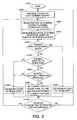
- FIG. 2is a flowchart of one exemplary embodiment of a method for controlling the control mechanism according to this invention
- FIG. 3is a perspective view of a first exemplary embodiment of a marking mechanism and a part of a position sensing system according to this invention
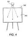
- FIG. 4is schematic representation of another part of the position sensing system according to the first embodiment of FIG. 3;
- FIG. 5is a plan view of a part of the position sensing system of a second exemplary embodiment of a marking mechanism and a part of a position sensing system according to this invention
- FIG. 6is a partial bottom view of a marking mechanism and another part of the position sensing system according to the second embodiment of FIG. 5;
- FIG. 7is a perspective view of a third exemplary embodiment of a marking mechanism and a part of a position sensing system according to this invention.
- FIG. 8is plan view of another part of the position sensing system according to the third embodiment of FIG. 7 .
- a whiteboard printing systemcomprises a marking mechanism that is moved over a surface of a whiteboard.
- a position sensing systemsenses a position of the marking mechanism relative to the whiteboard as the marking mechanism changes position.
- a control mechanismis used to actuate the marking mechanism.
- a stored image comprising image datais stored in a storage device.
- An image data signalis generated by the control mechanism for the image data based on the sensed position of the marking mechanism.
- the sensed positionis supplied to the control mechanism and the image data signal is supplied to the marking mechanism by a communication system based on the image stored in the storage device.
- the marking mechanismis thus actuated by the control mechanism based on the image data signal so that the stored image is printed onto the whiteboard.
- the marking mechanismcomprises a print head having a linear array of ink nozzles similar to those used in commercial inkjet printers.
- a print headhaving a linear array of ink nozzles similar to those used in commercial inkjet printers.
- the requirements of the whiteboard printer systems and methodsare somewhat different from ink-jet printers designed to print on a medium such as paper.
- the print headmust be designed to work with a form of dry-erase ink, and the print resolution need only be approximately 30 spots/inch instead of the 300 spots/inch required of standard ink-jet printers.
- the position of the marking mechanism and/or the print head on the whiteboardis determined in real time as the user performs a swipe.
- Various technologiesmay be employed to accomplish position sensing as further described below.
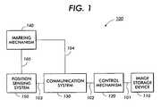
- FIG. 1shows a block diagram representing an exemplary embodiment of a whiteboard printer system 100 according to this invention.
- the whiteboard printer system 100may be used with a conventional whiteboard (not shown).
- the whiteboard printer system 100includes an image storage device 110 , a control mechanism 120 , a communication system 130 , a marking mechanism 140 and a position sensing system 150 . It should be understood that, while these elements are represented separately in the block diagram of FIG. 1, these elements are not necessarily separate and distinct components.
- Image data of an imageis stored by the image storage device 110 .
- the image storage device 110may be any suitable device, either known or hereafter developed, that is capable of at least temporarily storing image data in any known or later developed format.
- the image storage device 110may be a hard disk drive, a floppy disk or computer memory on/in which image data such as a portable digital document (PDD) may be stored in various formats, such as portable document format (PDF), or any known or later developed page-description language (PDL), graphics interchange format (GIF), joint photographic experts group format (JPEG), or JPEG file interchange format (JFIF).
- PDFportable document format
- GIFgraphics interchange format
- JPEGjoint photographic experts group format
- JFIFJPEG file interchange format
- the marking mechanism 140may be any suitable device, either known or hereafter developed, that is capable of reproducing the image or producing a representation of the image on the surface of the whiteboard.
- the marking mechanism 140comprises a print head, such as an ink-jet print head.
- the marking mechanismgenerally may be any suitable device, either known or hereafter developed, that is capable of reproducing the image or producing a representation of the image on a desired surface.
- the position sensing system 150may comprise any suitable device or arrangement of devices, either known or hereafter developed, that is capable of determining a position of the marking mechanism 140 relative to the whiteboard, or other desired surface, as the marking mechanism 140 is moved across the surface of the whiteboard, or other surface. In other words, the position sensing system 150 determines the location of the marking mechanism 140 on the surface of the whiteboard, or other surface, and tracks the marking mechanism 140 as it moves. Examples of suitable arrangements for the position sensing system 150 are described further below.
- the control mechanism 120may be any device or software structure that is capable of accessing the image data from the image storage device 110 and providing instructions to the marking mechanism 140 to reproduce the image, or at least a representation of the image. As described further below, the control mechanism 120 uses position information from the position sensing system 150 to determine the portion of the image data that is to be reproduced/represented on each corresponding portion of the whiteboard surface. The control mechanism 120 thus provides instructions to actuate the marking mechanism 140 appropriately as the marking mechanism 140 is moved over the surface of the whiteboard.
- the image storage device 110 , the control mechanism 120 , the communication system 130 , the marking mechanism 140 and the position sensing system 150are interconnected by links 101 , 102 , 103 , 104 and 105 .
- the links 101 - 105can be wired or wireless links or any other known or later developed element or elements that are capable of supplying electronic data to and from the connected elements 110 - 150 .
- the communication system 130may comprise any suitable device or arrangement of devices, either known or hereafter developed, that is capable of supplying electronic data from the position sensing system 150 to the control mechanism 120 and from the control mechanism 120 to the marking mechanism 140 .
- the communication system 130may comprise a distributed network, such as an intranet, an extranet, a local area network, a metropolitan area network, a wide area network, a satellite communication network, an infrared communication network, the Internet, the World Wide Web, or any other known or later developed distributed network.
- the communication system 130may also comprise wired or wireless links.
- the control mechanism 120may be operated by any suitable method either known or hereafter developed.
- the method illustrated in the exemplary flowchart of FIG. 2may be used to operate the control mechanism 120 so that each element of the marking mechanism 140 is actuated as required to print the stored image.
- the methodbegins in step S 100 , and continues to step S 200 , where the starting location, orientation and length of the marking mechanism 140 are initialized in a global coordinate system using fixed units having given origin and axes with respect to the stored image.
- the global coordinate systemmay be conveniently defined to be measured in inches, originating at an upper left comer of the stored image, with the x axis extending horizontally to the right across top edge of the stored image, and the y axis extending vertically downward along the left edge of the stored image.
- the initial location of the marking mechanism 140will be along the y axis. Since this invention employs global position sensing, the marking mechanism 140 may assume any starting location.
- the initial location of the marking mechanism 140will be “off” of the image, so that each marking element state is initialized to “white_pixel” (no printing) and each marking element last location is initialized to “off_the_image”.
- step S 300the motion of the marking mechanism 140 is tracked as the marking mechanism 140 is moved over the surface of the whiteboard.
- the position sensing system 150estimates the absolute x-y position of a pair of sensors relative to the initial location of the sensors, measurements can be referred to as “top_x, top_y” and “bottom_x, bottom_y”.
- the absolute x-y positionis thus expressed in the global coordinate system. If sensors of the position sensing system 150 provide velocity information about the marking mechanism 140 , then absolute position estimates can be obtained by numerical integration.
- each arraymay contain one entry for each marking element of the marking mechanism 140 , indexed sequentially from one end.
- One arrayis a current-state-array, where each entry has a white-pixel, black-pixel-need-to-fire, or black-pixel value.
- the other two arraysare a last-fired-x-array and a last-fired-y-array, where each entry has a floating value in the global coordinate system.
- a coordinate transformis performed to determine the location of the marking mechanism 140 in a stored image field pixel coordinate system based on the position of a given marking element of the marking mechanism 140 in the global coordinate system.
- step S 500a determination is made whether a pixel at that location in the stored image is black. If not, control continues to step S 600 . Otherwise, control jumps to step S 700 .
- step S 600the marking element state is set to “white_pixel”. Control then jumps to step S 100 .
- step S 700a determination is made whether the marking element state is set to “white_pixel”. If so, control proceeds to step S 800 . Otherwise, control jumps to step S 1000 .
- step S 800a determination is made whether the current location of the marking element is greater than a threshold distance from the location at which the marking element was last located.
- step S 900If the current location of the marking element is greater than a threshold distance from the location at which the marking element was last located, control continues to step S 900 . Otherwise control again jumps to step S 1000 .
- step S 900the marking element state is set to “black_need_to_fire” and the last location of the element is set to the current location of the marking element. Control then jumps to step S 1100 .
- step S 1000the marking element state is set to “black_pixel”. Control then continues to step S 1100 .
- step S 1100a determination is made whether the coordinate transform has been applied to all of the marking elements. If so, control returns to step S 200 . If not, control returns to step S 300 .
- the strategy of the methodis to look up the desired pixel in the stored image for each location of each marking element to determine if the individual marking elements are to be actuated to eject ink or otherwise mark the surface. Each time a marking element is actuated, the position of that marking element in the global coordinate system is stored. A marking element is not actuated if its current location is within a preset threshold distance from the location at which it was previously actuated, i.e., the stored position. This strategy leads to relatively uniform ink application regardless of the velocity or trajectory of the marking mechanism 140 , up to a maximum velocity depending on the cycle time required to address each of the marking elements.
- FIGS. 3 and 4show a first exemplary embodiment of a marking mechanism 240 and a position sensing system 250 , corresponding to the marking mechanism 140 and the position sensing system 150 .
- the marking mechanism 240comprises a hand-held device that resembles a squeegee.
- the marking mechanism 240includes a handle portion 242 and a print head portion 244 .
- the handle portion 242facilitates movement of the marking mechanism 240 across a whiteboard 260 , shown in FIG. 4, while keeping the print head portion 244 adjacent to a surface 262 of the whiteboard 260 .
- the print head portion 244includes a linear array of ink nozzles (not shown) that are capable of ejecting a dry-erase ink onto the surface 262 of the whiteboard 260 .
- ink-jet print head technologymay be modified to meet the particular requirements of the dry-erase ink used and the resolution desired.
- a tether 246is connected to the handle portion 242 of the marking mechanism 240 .
- the tether 246may comprise a wired link, as part of the communication system 130 , that carries electronic signals to and/or from the marking mechanism 240 .
- the tether 246also may comprise a wire that carries power to the print head portion 244 of the marking mechanism 240 .
- the tether 246also may comprise a flexible tube that carries ink to the print head portion 244 .
- a wireless linkmay be used instead of the tether 246 to transmit electronic signals to and/or from the marking mechanism 240 .
- a wireless linkmay employ radio frequency or infrared technology.
- infrared receivers and/or transmittersmay be located on the marking mechanism 240 .
- the communication system 130accordingly may comprise an infrared communication station, for example, mounted on the whiteboard 260 .
- the position sensing system 250is based on computer vision technology. This technology basically involves locating and tracking.
- a color video camera 252is positioned to view the whiteboard 260 and objects adjacent the surface 262 .
- the camera 252may be mounted above the whiteboard 260 and suspended from the ceiling.
- the camera 252is calibrated such that locations expressed in the coordinate system of the camera image can be translated to the coordinate system of the whiteboard 260 using well-known mathematics of projective geometry.
- the print head portion 244 of the marking mechanism 240can be colored or painted on a back surface, i.e., the surface facing away from the whiteboard 260 , with a pattern of distinctively colored and/or patterned fiducial markings 254 and 256 unlikely to be found elsewhere on the whiteboard, such as, for example, a lime green triangle 254 and a fluorescent pink circle 256 .
- the distinctive markings 254 and 256facilitate very fast locating and tracking of the marking mechanism 240 within the field of vision of the camera 252 using one or more segmentation techniques that are wellknown in the art.
- all pixels of the camera image that do not fall within the extreme range of the color space representing the distinctively colored markings 254 and 256 on the marking mechanism 240are set to black.
- the remaining “ON” pixels, those not set to black,are clustered.
- the centroid and first moment of inertiaare used to determine a location and orientation estimate of the print head portion 244 of the marking mechanism 240 within the camera image.
- a search algorithmis used to find the known elements of the colored pattern, the brightly colored markings 254 and 256 , and to fit these known elements to a geometric model reflecting their known arrangement on the print head portion 244 of the marking mechanism 240 .
- fast trackingis performed by searching the incoming video stream of the camera 252 for the fiducial markings 254 and 256 in a small region of the captured image predicted based on the last known position and determined motion of the marking mechanism 240 .
- fast tracking of known patternshas been demonstrated by Hager et al. For example, see The XVision System: A General-Purpose Substrate for Portable Real-Time Vision Applications , Computer Vision and Image Understanding 69(1) pp. 23-37.
- the well-known method of Kalman filtersmay be used to estimate both the position and velocity of the moving marking mechanism 240 .
- a mechanical techniquemay be used to augment the image-based information about the position of the marking mechanism 240 .
- one or more wheels 258may be mounted on the print head portion 244 of the marking mechanism 240 .
- a pair of wheels 258may be mounted at opposite ends of the print head portion 244 .
- the print head portion 244is supported on the wheels 258 in contact with the surface 262 of the whiteboard 260 .
- the wheels 258turn as the marking mechanism 240 moves across the whiteboard 260 and maintain a desired height of the print nozzles (not shown) above the surface 262 of the whiteboard 260 .
- the wheels 258may be instrumented with suitable rotary encoders capable of measuring the rotation of the wheels 258 with great precision. Since there may be a slight delay in the processing of image-based information by the camera 252 and delivery to the control mechanism, rotation information from the rotary encoders should help to improve the estimate of the instantaneous position of the marking mechanism 240 as it is swiped across the whiteboard 260 .
- FIGS. 5 and 6show a second exemplary embodiment of a marking mechanism 340 and a position sensing system 350 , corresponding to the marking mechanism 140 and the position sensing system 150 .
- a surface 362 of a whiteboard 360may be provided with glyph marks 370 .
- the glyph marks 370may be printed or otherwise applied to the surface 362 in such a way that they do not interfere with normal use of the whiteboard 360 , including printing according to this invention. While the glyph marks 370 are shown as placed on only a portion of the surface 362 , it should be understood that the glyph marks 370 may cover as much or as little of the whiteboard 360 as needed to provide accurate position information for the marking mechanism 340 .
- the glyph marks 370encode global position information that may be embedded in a glyph pattern including data glyphs, such as described in U.S. Pat. No. 5,939,703 to Hecht et al., incorporated herein by reference in its entirety.
- the glyph patternmay be represented by slash-like symbols 374 . These symbols 374 provide a generally homogeneous, unobtrusive appearance when viewed by the unaided eye under normal viewing conditions.
- each symbol 374may be read as a “1” or a “0” depending on its orientation.
- a front side, i.e., facing the whiteboard 360 , of a print head portion 344 of the marking mechanism 340includes a plurality of small video cameras 354 as part of the position sensing system 350 .
- the marking mechanism 340also may include one or more wheels 358 as described with respect to the first exemplary embodiment.
- the glyph marks 370may themselves augment the global positioning information by also providing local position information.
- the video cameras 354image the symbols 374 of the glyph marks 370 as the marking mechanism 340 moves over the surface 362 of the whiteboard 360 .
- a suitable controller(not shown) decodes or interprets the images of the video cameras 354 to determine the global position of the marking mechanism 340 relative to the whiteboard 360 .
- the plurality of video cameras 354allow the orientation of the marking mechanism 340 to be determined. Also, consecutive images may be used to provide additional information, such as direction and/or velocity, and/or local position information may be decoded from the glyph marks 370 .
- FIGS. 7 and 8show a third exemplary embodiment of a marking mechanism 440 and a position sensing system 450 , corresponding to the marking mechanism 140 and the position sensing system 150 .
- a plurality of ultrasound transducers 456are provided on a whiteboard 460 .
- four transducers 456may be used, one in each corner of the whiteboard 460 .
- a print head portion 442 of the marking mechanism 440includes at least one ultrasound transmitter 454 .
- the transmitter(s) 454 and transducers 456triangulate the position of the marking mechanism 440 on the whiteboard 460 .
- Any suitable combination of transmitter and transducers, either known or hereafter developed, and any suitable arrangement combination of the transmitter and the transducers,may be used.
- the marking mechanism 440also may include one or more wheels 458 as described with respect to the first exemplary embodiment.
- This inventionalso contemplates using optical scanning technology with laser position sensors, such as discussed in U.S. Pat. No. 5,585,605 to Williams et al., incorporated herein by reference in its entirety.
- the control mechanism 120uses the position information from the position sensing system 150 to determine which nozzles of the marking mechanism 140 to actuate. For example, given 2-D coordinates (x, y, ⁇ ) of the print head portion of the marking mechanism 140 on the whiteboard as the marking mechanism 140 moves, the control mechanism 120 looks up the colors of the pixel desired to be printed under each ink nozzle at a suitable time step or frequency, referring to the image data of the stored image. Since there may be a slight delay from the time pixel colors are looked up to the time they are printed, it may be necessary to “look ahead” and index pixels of the image data slightly ahead of the current location of each ink nozzle using the motion of the marking mechanism 140 as determined by the position sensing system 150 . The parameters of the look-ahead are determined by the actual performance of the whiteboard printer system 100 that is implemented.
- the whiteboard printer system 100 described abovemight be used in conjunction with a whiteboard image capture device in certain applications.
- a user of the whiteboard printer system 100may prepare for a meeting by preparing a detailed agenda in a text editor and recalling an engineering drawing from a CAD tool before the meeting starts.
- the userprints the agenda and drawing on the whiteboard in the meeting room using the using the whiteboard printer system 100 .
- the printed agendamay be modified by crossing out items, erasing items, and printing additional items, using conventional whiteboard eraser and markers.
- the engineering drawingmay be similarly modified.
- the whiteboardmay be scanned with a camera-based whiteboard scanner or other whiteboard image capture device.
- the image of the modified meeting agendamay then be emailed to all participants for their records.
- the marked-up engineering drawingmay be printed out and used for reference by a drafter who updates the CAD drawing.
- An additional exampleillustrates further possible application of the whiteboard printer system 100 for interactive editing of a whiteboard's contents on a several-minute time scale.
- the initial agendamay be modified, for example, using proofreader markup symbols.
- the image of the agendais scanned and the proofreader markings are interpreted by image understanding software to generate a new, modified agenda image.
- the updated agenda imagemay then be printed onto the whiteboard using the whiteboard printer system 100 .
- a diagrammatic user interfacecould be used to incrementally modify whiteboard images on a several-minute time scale, to permit functions such as: moving and scaling items on the whiteboard; rearranging list items; editing engineering drawings and schematics; removing ink of certain colors (e.g., text in black and annotations in red such that the annotations may be removed).
- the ability to print ink on a whiteboardopens a host of new uses for whiteboards in integration with electronic documents and electronic document services.
Landscapes
- Engineering & Computer Science (AREA)
- Multimedia (AREA)
- Signal Processing (AREA)
- Printers Characterized By Their Purpose (AREA)
- Ink Jet (AREA)
- Drawing Aids And Blackboards (AREA)
- Accessory Devices And Overall Control Thereof (AREA)
Abstract
Description
Claims (29)
Priority Applications (4)
| Application Number | Priority Date | Filing Date | Title |
|---|---|---|---|
| US09/854,592US6517266B2 (en) | 2001-05-15 | 2001-05-15 | Systems and methods for hand-held printing on a surface or medium |
| EP02253147.9AEP1259058B1 (en) | 2001-05-15 | 2002-05-03 | Hand-held printing system |
| JP2002132232AJP4898065B2 (en) | 2001-05-15 | 2002-05-08 | Hand-held printer system for whiteboard |
| BRPI0201808-0ABR0201808B1 (en) | 2001-05-15 | 2002-05-15 | portable printer system and method for marking on a surface using a portable printer. |
Applications Claiming Priority (1)
| Application Number | Priority Date | Filing Date | Title |
|---|---|---|---|
| US09/854,592US6517266B2 (en) | 2001-05-15 | 2001-05-15 | Systems and methods for hand-held printing on a surface or medium |
Publications (2)
| Publication Number | Publication Date |
|---|---|
| US20020171731A1 US20020171731A1 (en) | 2002-11-21 |
| US6517266B2true US6517266B2 (en) | 2003-02-11 |
Family
ID=25319105
Family Applications (1)
| Application Number | Title | Priority Date | Filing Date |
|---|---|---|---|
| US09/854,592Expired - LifetimeUS6517266B2 (en) | 2001-05-15 | 2001-05-15 | Systems and methods for hand-held printing on a surface or medium |
Country Status (4)
| Country | Link |
|---|---|
| US (1) | US6517266B2 (en) |
| EP (1) | EP1259058B1 (en) |
| JP (1) | JP4898065B2 (en) |
| BR (1) | BR0201808B1 (en) |
Cited By (92)
| Publication number | Priority date | Publication date | Assignee | Title |
|---|---|---|---|---|
| US20020190956A1 (en)* | 2001-05-02 | 2002-12-19 | Universal Electronics Inc. | Universal remote control with display and printer |
| US20030098897A1 (en)* | 2001-11-28 | 2003-05-29 | Fuji Photo Film Co., Ltd. | Scanning printing apparatus and printing method used therein |
| WO2003068515A1 (en)* | 2002-02-13 | 2003-08-21 | Silverbrook Research Pty. Ltd. | Manually moveable printer with speed sensor |
| US20030209369A1 (en)* | 2002-05-10 | 2003-11-13 | Rafi Holtzman | Methods and apparatus for configuring a writing surface |
| US20040027414A1 (en)* | 2002-08-12 | 2004-02-12 | Miguel Boleda | Printing on surfaces |
| US20040027443A1 (en)* | 2002-08-12 | 2004-02-12 | Trent Jonathan Louis | Hand held electronic paint brush |
| US20040109034A1 (en)* | 2002-10-18 | 2004-06-10 | Hewlett-Packard Development Company, Lp. | Hybrid printing/pointing device |
| US6773177B2 (en)* | 2001-09-14 | 2004-08-10 | Fuji Xerox Co., Ltd. | Method and system for position-aware freeform printing within a position-sensed area |
| US20040175042A1 (en)* | 2003-03-03 | 2004-09-09 | Wallace Kroeker | System and method for capturing images of a target area on which information is recorded |
| US20040263888A1 (en)* | 2003-06-30 | 2004-12-30 | Tecu Kirk S. | Apparatus and method for printing an image on a print medium |
| US20050022686A1 (en)* | 2003-07-28 | 2005-02-03 | Dreampatch, Llc | Apparatus, method, and computer program product for animation pad transfer |
| US20050025532A1 (en)* | 2003-07-28 | 2005-02-03 | Dreampatch, Llc, A California Limited Liability Corporation | Apparatus and method for image capture and pad transfer |
| US20050025555A1 (en)* | 2003-07-28 | 2005-02-03 | Dreampatch, Llc | Apparatus, method, and computer program product for pad transfer |
| US20050100680A1 (en)* | 2002-01-24 | 2005-05-12 | Burkhard Bustgens | Method for applying paints and varnishes |
| US20050135857A1 (en)* | 2003-12-18 | 2005-06-23 | Xerox Corporation | Hand-propelled wand printer |
| WO2005070684A1 (en) | 2004-01-15 | 2005-08-04 | Koninklijke Philips Electronics, N.V. | Electronic paint brush scanner and dispensers |
| US20050193292A1 (en)* | 2004-01-06 | 2005-09-01 | Microsoft Corporation | Enhanced approach of m-array decoding and error correction |
| US20050196543A1 (en)* | 2004-02-02 | 2005-09-08 | Morton John S. | Cost effective automated preparation and coating methodology for large surfaces |
| US6952880B2 (en)* | 2001-08-27 | 2005-10-11 | Hewlett-Packard Development Company, L.P. | Measurement and marking device |
| US20050259084A1 (en)* | 2004-05-21 | 2005-11-24 | Popovich David G | Tiled touch system |
| US20060016357A1 (en)* | 2004-07-13 | 2006-01-26 | Man Roland Druckmaschinen Ag | Web-fed rotary printing unit |
| US20060133648A1 (en)* | 2004-12-17 | 2006-06-22 | Xerox Corporation. | Identifying objects tracked in images using active device |
| US20060182309A1 (en)* | 2002-10-31 | 2006-08-17 | Microsoft Corporation | Passive embedded interaction coding |
| US20060190818A1 (en)* | 2005-02-18 | 2006-08-24 | Microsoft Corporation | Embedded interaction code document |
| US7101097B2 (en) | 2003-07-28 | 2006-09-05 | Wessells Philip G | Apparatus and method for pad printing |
| US20060215913A1 (en)* | 2005-03-24 | 2006-09-28 | Microsoft Corporation | Maze pattern analysis with image matching |
| US20060221403A1 (en)* | 2003-01-23 | 2006-10-05 | Francois Bancel | Device for printing an image on a large surface |
| US20060242562A1 (en)* | 2005-04-22 | 2006-10-26 | Microsoft Corporation | Embedded method for embedded interaction code array |
| US20060274948A1 (en)* | 2005-06-02 | 2006-12-07 | Microsoft Corporation | Stroke localization and binding to electronic document |
| US20070041654A1 (en)* | 2005-08-17 | 2007-02-22 | Microsoft Corporation | Embedded interaction code enabled surface type identification |
| US20070042165A1 (en)* | 2005-08-17 | 2007-02-22 | Microsoft Corporation | Embedded interaction code enabled display |
| US20070092325A1 (en)* | 2005-10-21 | 2007-04-26 | Studer Anthony D | Hand-held printing device |
| US20070092324A1 (en)* | 2005-10-21 | 2007-04-26 | Studer Anthony D | Device and method for printing |
| US20070165007A1 (en)* | 2006-01-13 | 2007-07-19 | Gerald Morrison | Interactive input system |
| US20070205994A1 (en)* | 2006-03-02 | 2007-09-06 | Taco Van Ieperen | Touch system and method for interacting with the same |
| US20070263062A1 (en)* | 2006-05-09 | 2007-11-15 | Noe Gary L | Handheld Printing with Reference Indicia |
| US20070263063A1 (en)* | 2006-05-10 | 2007-11-15 | Lexmark International, Inc. | Handheld printer minimizing printing defects |
| US20080025612A1 (en)* | 2004-01-16 | 2008-01-31 | Microsoft Corporation | Strokes Localization by m-Array Decoding and Fast Image Matching |
| US20080068352A1 (en)* | 2004-02-17 | 2008-03-20 | Smart Technologies Inc. | Apparatus for detecting a pointer within a region of interest |
| US20080215286A1 (en)* | 2007-03-02 | 2008-09-04 | Mealy James | Apparatus and method for determining the position of a device |
| US20080213018A1 (en)* | 2007-03-02 | 2008-09-04 | Mealy James | Hand-propelled scrapbooking printer |
| US20080259053A1 (en)* | 2007-04-11 | 2008-10-23 | John Newton | Touch Screen System with Hover and Click Input Methods |
| US20080284733A1 (en)* | 2004-01-02 | 2008-11-20 | Smart Technologies Inc. | Pointer tracking across multiple overlapping coordinate input sub-regions defining a generally contiguous input region |
| US20090027241A1 (en)* | 2005-05-31 | 2009-01-29 | Microsoft Corporation | Fast error-correcting of embedded interaction codes |
| US20090058833A1 (en)* | 2007-08-30 | 2009-03-05 | John Newton | Optical Touchscreen with Improved Illumination |
| US20090067743A1 (en)* | 2005-05-25 | 2009-03-12 | Microsoft Corporation | Preprocessing for information pattern analysis |
| US20090146973A1 (en)* | 2004-04-29 | 2009-06-11 | Smart Technologies Ulc | Dual mode touch systems |
| US20090146972A1 (en)* | 2004-05-05 | 2009-06-11 | Smart Technologies Ulc | Apparatus and method for detecting a pointer relative to a touch surface |
| US20090160801A1 (en)* | 2003-03-11 | 2009-06-25 | Smart Technologies Ulc | System and method for differentiating between pointers used to contact touch surface |
| US20090207144A1 (en)* | 2008-01-07 | 2009-08-20 | Next Holdings Limited | Position Sensing System With Edge Positioning Enhancement |
| US20090213094A1 (en)* | 2008-01-07 | 2009-08-27 | Next Holdings Limited | Optical Position Sensing System and Optical Position Sensor Assembly |
| US20090213093A1 (en)* | 2008-01-07 | 2009-08-27 | Next Holdings Limited | Optical position sensor using retroreflection |
| US7599560B2 (en) | 2005-04-22 | 2009-10-06 | Microsoft Corporation | Embedded interaction code recognition |
| US20090277697A1 (en)* | 2008-05-09 | 2009-11-12 | Smart Technologies Ulc | Interactive Input System And Pen Tool Therefor |
| US20090277694A1 (en)* | 2008-05-09 | 2009-11-12 | Smart Technologies Ulc | Interactive Input System And Bezel Therefor |
| US20090278794A1 (en)* | 2008-05-09 | 2009-11-12 | Smart Technologies Ulc | Interactive Input System With Controlled Lighting |
| US7619607B2 (en) | 2005-06-30 | 2009-11-17 | Microsoft Corporation | Embedding a pattern design onto a liquid crystal display |
| US7619617B2 (en) | 2002-11-15 | 2009-11-17 | Smart Technologies Ulc | Size/scale and orientation determination of a pointer in a camera-based touch system |
| US20090313547A1 (en)* | 2005-10-21 | 2009-12-17 | Bebo, Inc. | Multi-media tool for creating and transmitting artistic works |
| US20090309839A1 (en)* | 2008-06-13 | 2009-12-17 | Polyvision Corporation | Eraser assemblies and methods of manufacturing same |
| US7639885B2 (en) | 2002-10-31 | 2009-12-29 | Microsoft Corporation | Decoding and error correction in 2-D arrays |
| US7643006B2 (en) | 2003-09-16 | 2010-01-05 | Smart Technologies Ulc | Gesture recognition method and touch system incorporating the same |
| US20100079385A1 (en)* | 2008-09-29 | 2010-04-01 | Smart Technologies Ulc | Method for calibrating an interactive input system and interactive input system executing the calibration method |
| US20100090985A1 (en)* | 2003-02-14 | 2010-04-15 | Next Holdings Limited | Touch screen signal processing |
| US20100110005A1 (en)* | 2008-11-05 | 2010-05-06 | Smart Technologies Ulc | Interactive input system with multi-angle reflector |
| US20100207911A1 (en)* | 2003-02-14 | 2010-08-19 | Next Holdings Limited | Touch screen Signal Processing With Single-Point Calibration |
| US20100225588A1 (en)* | 2009-01-21 | 2010-09-09 | Next Holdings Limited | Methods And Systems For Optical Detection Of Gestures |
| US20100229090A1 (en)* | 2009-03-05 | 2010-09-09 | Next Holdings Limited | Systems and Methods for Interacting With Touch Displays Using Single-Touch and Multi-Touch Gestures |
| US7826074B1 (en) | 2005-02-25 | 2010-11-02 | Microsoft Corporation | Fast embedded interaction code printing with custom postscript commands |
| US20110057869A1 (en)* | 2009-09-08 | 2011-03-10 | Parc | Mobile writer for erasable media |
| US20110095977A1 (en)* | 2009-10-23 | 2011-04-28 | Smart Technologies Ulc | Interactive input system incorporating multi-angle reflecting structure |
| US20110199387A1 (en)* | 2009-11-24 | 2011-08-18 | John David Newton | Activating Features on an Imaging Device Based on Manipulations |
| US20110205189A1 (en)* | 2008-10-02 | 2011-08-25 | John David Newton | Stereo Optical Sensors for Resolving Multi-Touch in a Touch Detection System |
| US20110205151A1 (en)* | 2009-12-04 | 2011-08-25 | John David Newton | Methods and Systems for Position Detection |
| US20110221666A1 (en)* | 2009-11-24 | 2011-09-15 | Not Yet Assigned | Methods and Apparatus For Gesture Recognition Mode Control |
| US20110234542A1 (en)* | 2010-03-26 | 2011-09-29 | Paul Marson | Methods and Systems Utilizing Multiple Wavelengths for Position Detection |
| USRE42794E1 (en) | 1999-12-27 | 2011-10-04 | Smart Technologies Ulc | Information-inputting device inputting contact point of object on recording surfaces as information |
| US8055022B2 (en) | 2000-07-05 | 2011-11-08 | Smart Technologies Ulc | Passive touch system and method of detecting user input |
| US8079765B1 (en)* | 2007-03-02 | 2011-12-20 | Marvell International Ltd. | Hand-propelled labeling printer |
| USRE43084E1 (en) | 1999-10-29 | 2012-01-10 | Smart Technologies Ulc | Method and apparatus for inputting information including coordinate data |
| US8094137B2 (en) | 2007-07-23 | 2012-01-10 | Smart Technologies Ulc | System and method of detecting contact on a display |
| US8096713B1 (en)* | 2007-03-02 | 2012-01-17 | Marvell International Ltd. | Managing project information with a hand-propelled device |
| US8123349B2 (en) | 2007-01-31 | 2012-02-28 | Hewlett-Packard Development Company, L.P. | Automatic image color and contrast optimization system based on cartridge identification |
| US8149221B2 (en) | 2004-05-07 | 2012-04-03 | Next Holdings Limited | Touch panel display system with illumination and detection provided from a single edge |
| US8156153B2 (en) | 2005-04-22 | 2012-04-10 | Microsoft Corporation | Global metadata embedding and decoding |
| US8384693B2 (en) | 2007-08-30 | 2013-02-26 | Next Holdings Limited | Low profile touch panel systems |
| US8456418B2 (en) | 2003-10-09 | 2013-06-04 | Smart Technologies Ulc | Apparatus for determining the location of a pointer within a region of interest |
| US8456447B2 (en) | 2003-02-14 | 2013-06-04 | Next Holdings Limited | Touch screen signal processing |
| US8692768B2 (en) | 2009-07-10 | 2014-04-08 | Smart Technologies Ulc | Interactive input system |
| US8705117B1 (en) | 2007-06-18 | 2014-04-22 | Marvell International Ltd. | Hand-held printing device and method for tuning ink jet color for printing on colored paper |
| US9442607B2 (en) | 2006-12-04 | 2016-09-13 | Smart Technologies Inc. | Interactive input system and method |
| US11858277B2 (en) | 2019-04-29 | 2024-01-02 | Hewlett-Packard Development Company, L.P. | Rotating housing with sensor |
Families Citing this family (14)
| Publication number | Priority date | Publication date | Assignee | Title |
|---|---|---|---|---|
| US20020196482A1 (en)* | 2001-06-26 | 2002-12-26 | Hoberock Tim M. | Dry erase printer presentation board |
| SE527211C2 (en)* | 2002-03-11 | 2006-01-17 | Printdreams Europ Ab | Sensor and print head unit of a hand operated handwriting device |
| US20040018345A1 (en)* | 2002-07-26 | 2004-01-29 | Athorn-Telep Yvonne K. | Dry-erase ink marking media |
| US7876472B2 (en)* | 2006-10-12 | 2011-01-25 | Ricoh Co. Ltd. | Handheld printer and method of operation |
| WO2008109557A1 (en)* | 2007-03-02 | 2008-09-12 | Marvell World Trade Ltd. | Dynamic image dithering |
| US20080219737A1 (en)* | 2007-03-07 | 2008-09-11 | Michael David Stilz | Hand Held Printer Having A Doppler Position Sensor |
| TW200919298A (en)* | 2007-08-01 | 2009-05-01 | Silverbrook Res Pty Ltd | Interactive handheld scanner |
| EP2259928B1 (en) | 2008-03-18 | 2013-12-25 | Marvell World Trade Ltd. | Handheld mobile printing device capable of real-time in-line tagging of print surfaces |
| KR101599876B1 (en)* | 2009-04-15 | 2016-03-14 | 삼성전자주식회사 | Handheld printer and printing method thereof |
| FR2952450B1 (en)* | 2009-11-12 | 2012-06-08 | Commissariat Energie Atomique | PORTABLE DEVICE AND METHOD FOR PRINTING AN IMAGE, RECORDING MEDIUM, PEN AND TERMINAL FOR THIS DEVICE |
| JP6330531B2 (en)* | 2014-07-08 | 2018-05-30 | 株式会社リコー | Image recording system and image recording method |
| JP6384262B2 (en)* | 2014-10-20 | 2018-09-05 | 株式会社リコー | Printing apparatus, method and program |
| US10369781B2 (en) | 2015-01-08 | 2019-08-06 | Hewlett-Packard Development Company, L.P. | Mobile printers |
| UA129580U (en)* | 2018-03-05 | 2018-11-12 | Джеспер Денніс Шліманн | MANUAL PORTABLE DRAWING PLOTER |
Citations (13)
| Publication number | Priority date | Publication date | Assignee | Title |
|---|---|---|---|---|
| JPS6129563A (en)* | 1984-07-20 | 1986-02-10 | Hitachi Ltd | small manual printer |
| US4814552A (en) | 1987-12-02 | 1989-03-21 | Xerox Corporation | Ultrasound position input device |
| US5585605A (en) | 1993-11-05 | 1996-12-17 | Microfield Graphics, Inc. | Optical-scanning system employing laser and laser safety control |
| US5825995A (en)* | 1996-03-11 | 1998-10-20 | Intermec Technologies, Inc. | Printer with motion detection |
| US5829893A (en)* | 1996-07-16 | 1998-11-03 | Brother Kogyo Kabushiki Kaisha | Portable printing device |
| US5927872A (en)* | 1997-08-08 | 1999-07-27 | Hewlett-Packard Company | Handy printer system |
| US5939703A (en) | 1995-01-03 | 1999-08-17 | Xerox Corporation | Distributed dimensional labeling for dimensional characterization of embedded data blocks |
| US6000946A (en)* | 1998-03-09 | 1999-12-14 | Hewlett-Packard Company | Collaborative drawing device |
| US6202096B1 (en)* | 1997-04-15 | 2001-03-13 | Hewlett-Packard Company | Method and apparatus for device interaction by protocol |
| US6229565B1 (en)* | 1997-08-15 | 2001-05-08 | Howard H. Bobry | Hand-held electronic camera with integral printer |
| US6318825B1 (en)* | 1998-10-23 | 2001-11-20 | Hewlett-Packard Company | Dry erase electronic whiteboard with page-wide-array inkjet printer |
| US6357939B1 (en)* | 2001-02-02 | 2002-03-19 | Hewlett-Packard Company | Method of and apparatus for handheld printing of images on a media |
| US6368002B1 (en)* | 1999-11-29 | 2002-04-09 | Xerox Corporation | Parking mechanism for storing and exchanging end effectors used in a system for performing actions over vertical surfaces |
Family Cites Families (5)
| Publication number | Priority date | Publication date | Assignee | Title |
|---|---|---|---|---|
| JPH06178366A (en)* | 1992-12-04 | 1994-06-24 | Canon Inc | Image forming system |
| JPH1035029A (en)* | 1996-07-23 | 1998-02-10 | Brother Ind Ltd | Manual printing device |
| US6618078B1 (en)* | 1998-04-17 | 2003-09-09 | Hewlett-Packard Development Company, L.P. | Digital camera capable of printing captured images in various sizes |
| JP2001043173A (en)* | 1999-08-03 | 2001-02-16 | Konica Corp | Information equipment, information processor, and method for generating layout map of information equipment |
| JP2001253121A (en)* | 2000-03-09 | 2001-09-18 | Seiko Epson Corp | Manual printing device |
- 2001
- 2001-05-15USUS09/854,592patent/US6517266B2/ennot_activeExpired - Lifetime
- 2002
- 2002-05-03EPEP02253147.9Apatent/EP1259058B1/ennot_activeExpired - Lifetime
- 2002-05-08JPJP2002132232Apatent/JP4898065B2/ennot_activeExpired - Fee Related
- 2002-05-15BRBRPI0201808-0Apatent/BR0201808B1/ennot_activeIP Right Cessation
Patent Citations (13)
| Publication number | Priority date | Publication date | Assignee | Title |
|---|---|---|---|---|
| JPS6129563A (en)* | 1984-07-20 | 1986-02-10 | Hitachi Ltd | small manual printer |
| US4814552A (en) | 1987-12-02 | 1989-03-21 | Xerox Corporation | Ultrasound position input device |
| US5585605A (en) | 1993-11-05 | 1996-12-17 | Microfield Graphics, Inc. | Optical-scanning system employing laser and laser safety control |
| US5939703A (en) | 1995-01-03 | 1999-08-17 | Xerox Corporation | Distributed dimensional labeling for dimensional characterization of embedded data blocks |
| US5825995A (en)* | 1996-03-11 | 1998-10-20 | Intermec Technologies, Inc. | Printer with motion detection |
| US5829893A (en)* | 1996-07-16 | 1998-11-03 | Brother Kogyo Kabushiki Kaisha | Portable printing device |
| US6202096B1 (en)* | 1997-04-15 | 2001-03-13 | Hewlett-Packard Company | Method and apparatus for device interaction by protocol |
| US5927872A (en)* | 1997-08-08 | 1999-07-27 | Hewlett-Packard Company | Handy printer system |
| US6229565B1 (en)* | 1997-08-15 | 2001-05-08 | Howard H. Bobry | Hand-held electronic camera with integral printer |
| US6000946A (en)* | 1998-03-09 | 1999-12-14 | Hewlett-Packard Company | Collaborative drawing device |
| US6318825B1 (en)* | 1998-10-23 | 2001-11-20 | Hewlett-Packard Company | Dry erase electronic whiteboard with page-wide-array inkjet printer |
| US6368002B1 (en)* | 1999-11-29 | 2002-04-09 | Xerox Corporation | Parking mechanism for storing and exchanging end effectors used in a system for performing actions over vertical surfaces |
| US6357939B1 (en)* | 2001-02-02 | 2002-03-19 | Hewlett-Packard Company | Method of and apparatus for handheld printing of images on a media |
Non-Patent Citations (1)
| Title |
|---|
| The XVision System: A General-Purpose Substrate for Portable Real-Time Vision Applications, Gregory D. Hager et al. Computer Vision and Image Understanding 69 (1) pp. 23-37. |
Cited By (154)
| Publication number | Priority date | Publication date | Assignee | Title |
|---|---|---|---|---|
| USRE43084E1 (en) | 1999-10-29 | 2012-01-10 | Smart Technologies Ulc | Method and apparatus for inputting information including coordinate data |
| USRE42794E1 (en) | 1999-12-27 | 2011-10-04 | Smart Technologies Ulc | Information-inputting device inputting contact point of object on recording surfaces as information |
| US8203535B2 (en) | 2000-07-05 | 2012-06-19 | Smart Technologies Ulc | Passive touch system and method of detecting user input |
| US8055022B2 (en) | 2000-07-05 | 2011-11-08 | Smart Technologies Ulc | Passive touch system and method of detecting user input |
| US8378986B2 (en) | 2000-07-05 | 2013-02-19 | Smart Technologies Ulc | Passive touch system and method of detecting user input |
| US20020190956A1 (en)* | 2001-05-02 | 2002-12-19 | Universal Electronics Inc. | Universal remote control with display and printer |
| US6859197B2 (en)* | 2001-05-02 | 2005-02-22 | Universal Electronics Inc. | Universal remote control with display and printer |
| US6952880B2 (en)* | 2001-08-27 | 2005-10-11 | Hewlett-Packard Development Company, L.P. | Measurement and marking device |
| US6773177B2 (en)* | 2001-09-14 | 2004-08-10 | Fuji Xerox Co., Ltd. | Method and system for position-aware freeform printing within a position-sensed area |
| US20030098897A1 (en)* | 2001-11-28 | 2003-05-29 | Fuji Photo Film Co., Ltd. | Scanning printing apparatus and printing method used therein |
| US6709085B2 (en)* | 2001-11-28 | 2004-03-23 | Fuji Photo Film Co., Ltd. | Scanning printing apparatus and printing method used therein |
| US7981462B2 (en)* | 2002-01-24 | 2011-07-19 | Burkhard Büstgens | Method for applying paints and varnishes |
| US20050100680A1 (en)* | 2002-01-24 | 2005-05-12 | Burkhard Bustgens | Method for applying paints and varnishes |
| US8029130B2 (en) | 2002-02-13 | 2011-10-04 | Silverbrook Research Pty Ltd | Hand-held printer with capping device |
| US20090058922A1 (en)* | 2002-02-13 | 2009-03-05 | Silverbrook Research Pty Ltd | Handheld printer with movement sensor and body including elongate molding with recess |
| US7252379B2 (en) | 2002-02-13 | 2007-08-07 | Silverbrook Research Pty Ltd | Manually moveable printer with speed sensor |
| WO2003068515A1 (en)* | 2002-02-13 | 2003-08-21 | Silverbrook Research Pty. Ltd. | Manually moveable printer with speed sensor |
| US20050104914A1 (en)* | 2002-02-13 | 2005-05-19 | Kia Silverbrook | Manually moveable printer with speed sensor |
| US20090115813A1 (en)* | 2002-02-13 | 2009-05-07 | Silverbrook Research Pty Ltd | Hand-held printer with capping device |
| US20070182805A1 (en)* | 2002-02-13 | 2007-08-09 | Silverbrook Research Pty Ltd | Hand-Held Printer With Movement Sensor |
| US7470021B2 (en) | 2002-02-13 | 2008-12-30 | Silverbrook Research Pty Ltd | Hand-held printer with movement sensor |
| US20030209369A1 (en)* | 2002-05-10 | 2003-11-13 | Rafi Holtzman | Methods and apparatus for configuring a writing surface |
| US6875933B2 (en)* | 2002-05-10 | 2005-04-05 | Luidia Inc. | Methods and apparatus for configuring a writing surface |
| US6942335B2 (en)* | 2002-08-12 | 2005-09-13 | Jonathan Louis Trent | Hand held electronic paint brush |
| US20040027414A1 (en)* | 2002-08-12 | 2004-02-12 | Miguel Boleda | Printing on surfaces |
| US20040027443A1 (en)* | 2002-08-12 | 2004-02-12 | Trent Jonathan Louis | Hand held electronic paint brush |
| US20040109034A1 (en)* | 2002-10-18 | 2004-06-10 | Hewlett-Packard Development Company, Lp. | Hybrid printing/pointing device |
| US7639885B2 (en) | 2002-10-31 | 2009-12-29 | Microsoft Corporation | Decoding and error correction in 2-D arrays |
| US20060182309A1 (en)* | 2002-10-31 | 2006-08-17 | Microsoft Corporation | Passive embedded interaction coding |
| US7684618B2 (en) | 2002-10-31 | 2010-03-23 | Microsoft Corporation | Passive embedded interaction coding |
| US8228304B2 (en) | 2002-11-15 | 2012-07-24 | Smart Technologies Ulc | Size/scale orientation determination of a pointer in a camera-based touch system |
| US7619617B2 (en) | 2002-11-15 | 2009-11-17 | Smart Technologies Ulc | Size/scale and orientation determination of a pointer in a camera-based touch system |
| US20100060613A1 (en)* | 2002-11-15 | 2010-03-11 | Smart Technologies Ulc | Size/scale orientation determination of a pointer in a camera-based touch system |
| US20060221403A1 (en)* | 2003-01-23 | 2006-10-05 | Francois Bancel | Device for printing an image on a large surface |
| US8466885B2 (en) | 2003-02-14 | 2013-06-18 | Next Holdings Limited | Touch screen signal processing |
| US20100207911A1 (en)* | 2003-02-14 | 2010-08-19 | Next Holdings Limited | Touch screen Signal Processing With Single-Point Calibration |
| US8289299B2 (en) | 2003-02-14 | 2012-10-16 | Next Holdings Limited | Touch screen signal processing |
| US8456447B2 (en) | 2003-02-14 | 2013-06-04 | Next Holdings Limited | Touch screen signal processing |
| US20100090985A1 (en)* | 2003-02-14 | 2010-04-15 | Next Holdings Limited | Touch screen signal processing |
| US8508508B2 (en) | 2003-02-14 | 2013-08-13 | Next Holdings Limited | Touch screen signal processing with single-point calibration |
| US20040175042A1 (en)* | 2003-03-03 | 2004-09-09 | Wallace Kroeker | System and method for capturing images of a target area on which information is recorded |
| US8103057B2 (en) | 2003-03-03 | 2012-01-24 | Smart Technologies Ulc | System and method for capturing images of a target area on which information is recorded |
| US7684624B2 (en) | 2003-03-03 | 2010-03-23 | Smart Technologies Ulc | System and method for capturing images of a target area on which information is recorded |
| US20100149349A1 (en)* | 2003-03-03 | 2010-06-17 | Smart Technologies Ulc | System and method for capturing images of a target area on which information is recorded |
| US8456451B2 (en) | 2003-03-11 | 2013-06-04 | Smart Technologies Ulc | System and method for differentiating between pointers used to contact touch surface |
| US20090160801A1 (en)* | 2003-03-11 | 2009-06-25 | Smart Technologies Ulc | System and method for differentiating between pointers used to contact touch surface |
| US20040263888A1 (en)* | 2003-06-30 | 2004-12-30 | Tecu Kirk S. | Apparatus and method for printing an image on a print medium |
| US20050025555A1 (en)* | 2003-07-28 | 2005-02-03 | Dreampatch, Llc | Apparatus, method, and computer program product for pad transfer |
| US20050025532A1 (en)* | 2003-07-28 | 2005-02-03 | Dreampatch, Llc, A California Limited Liability Corporation | Apparatus and method for image capture and pad transfer |
| US6971806B2 (en) | 2003-07-28 | 2005-12-06 | Wessells Philip G | Apparatus, method, and computer program product for pad transfer |
| US20050022686A1 (en)* | 2003-07-28 | 2005-02-03 | Dreampatch, Llc | Apparatus, method, and computer program product for animation pad transfer |
| US6975827B2 (en) | 2003-07-28 | 2005-12-13 | Wessells Philip G | Apparatus and method for image capture and pad transfer |
| US7101097B2 (en) | 2003-07-28 | 2006-09-05 | Wessells Philip G | Apparatus and method for pad printing |
| US7643006B2 (en) | 2003-09-16 | 2010-01-05 | Smart Technologies Ulc | Gesture recognition method and touch system incorporating the same |
| US8456418B2 (en) | 2003-10-09 | 2013-06-04 | Smart Technologies Ulc | Apparatus for determining the location of a pointer within a region of interest |
| US20050135857A1 (en)* | 2003-12-18 | 2005-06-23 | Xerox Corporation | Hand-propelled wand printer |
| US7246958B2 (en) | 2003-12-18 | 2007-07-24 | Xerox Corporation | Hand-propelled wand printer |
| US20080284733A1 (en)* | 2004-01-02 | 2008-11-20 | Smart Technologies Inc. | Pointer tracking across multiple overlapping coordinate input sub-regions defining a generally contiguous input region |
| US8089462B2 (en) | 2004-01-02 | 2012-01-03 | Smart Technologies Ulc | Pointer tracking across multiple overlapping coordinate input sub-regions defining a generally contiguous input region |
| US20050193292A1 (en)* | 2004-01-06 | 2005-09-01 | Microsoft Corporation | Enhanced approach of m-array decoding and error correction |
| US7583842B2 (en) | 2004-01-06 | 2009-09-01 | Microsoft Corporation | Enhanced approach of m-array decoding and error correction |
| WO2005070684A1 (en) | 2004-01-15 | 2005-08-04 | Koninklijke Philips Electronics, N.V. | Electronic paint brush scanner and dispensers |
| US7815305B2 (en) | 2004-01-15 | 2010-10-19 | Koninklijke Philips Electronics N.V. | Electronic paint brush with scanner and dispensers |
| US20090141112A1 (en)* | 2004-01-15 | 2009-06-04 | Koninklijke Philips Electronics N V | Electronic paint brush with scanner and dispensers |
| US20080025612A1 (en)* | 2004-01-16 | 2008-01-31 | Microsoft Corporation | Strokes Localization by m-Array Decoding and Fast Image Matching |
| US7570813B2 (en) | 2004-01-16 | 2009-08-04 | Microsoft Corporation | Strokes localization by m-array decoding and fast image matching |
| US20050196543A1 (en)* | 2004-02-02 | 2005-09-08 | Morton John S. | Cost effective automated preparation and coating methodology for large surfaces |
| US7934467B2 (en) | 2004-02-02 | 2011-05-03 | John Stephen Morton | Cost effective automated preparation and coating methodology for large surfaces |
| US20080068352A1 (en)* | 2004-02-17 | 2008-03-20 | Smart Technologies Inc. | Apparatus for detecting a pointer within a region of interest |
| US8274496B2 (en) | 2004-04-29 | 2012-09-25 | Smart Technologies Ulc | Dual mode touch systems |
| US20090146973A1 (en)* | 2004-04-29 | 2009-06-11 | Smart Technologies Ulc | Dual mode touch systems |
| US20090146972A1 (en)* | 2004-05-05 | 2009-06-11 | Smart Technologies Ulc | Apparatus and method for detecting a pointer relative to a touch surface |
| US8149221B2 (en) | 2004-05-07 | 2012-04-03 | Next Holdings Limited | Touch panel display system with illumination and detection provided from a single edge |
| US20050259084A1 (en)* | 2004-05-21 | 2005-11-24 | Popovich David G | Tiled touch system |
| US8120596B2 (en) | 2004-05-21 | 2012-02-21 | Smart Technologies Ulc | Tiled touch system |
| US20060016357A1 (en)* | 2004-07-13 | 2006-01-26 | Man Roland Druckmaschinen Ag | Web-fed rotary printing unit |
| US7540239B2 (en)* | 2004-07-13 | 2009-06-02 | Manroland Ag | Web-fed rotary printing unit |
| US20060133648A1 (en)* | 2004-12-17 | 2006-06-22 | Xerox Corporation. | Identifying objects tracked in images using active device |
| US7505607B2 (en) | 2004-12-17 | 2009-03-17 | Xerox Corporation | Identifying objects tracked in images using active device |
| US20060190818A1 (en)* | 2005-02-18 | 2006-08-24 | Microsoft Corporation | Embedded interaction code document |
| US7607076B2 (en)* | 2005-02-18 | 2009-10-20 | Microsoft Corporation | Embedded interaction code document |
| US7826074B1 (en) | 2005-02-25 | 2010-11-02 | Microsoft Corporation | Fast embedded interaction code printing with custom postscript commands |
| US20060215913A1 (en)* | 2005-03-24 | 2006-09-28 | Microsoft Corporation | Maze pattern analysis with image matching |
| US7599560B2 (en) | 2005-04-22 | 2009-10-06 | Microsoft Corporation | Embedded interaction code recognition |
| US8156153B2 (en) | 2005-04-22 | 2012-04-10 | Microsoft Corporation | Global metadata embedding and decoding |
| US20060242562A1 (en)* | 2005-04-22 | 2006-10-26 | Microsoft Corporation | Embedded method for embedded interaction code array |
| US20090067743A1 (en)* | 2005-05-25 | 2009-03-12 | Microsoft Corporation | Preprocessing for information pattern analysis |
| US7920753B2 (en) | 2005-05-25 | 2011-04-05 | Microsoft Corporation | Preprocessing for information pattern analysis |
| US20090027241A1 (en)* | 2005-05-31 | 2009-01-29 | Microsoft Corporation | Fast error-correcting of embedded interaction codes |
| US7729539B2 (en) | 2005-05-31 | 2010-06-01 | Microsoft Corporation | Fast error-correcting of embedded interaction codes |
| US20060274948A1 (en)* | 2005-06-02 | 2006-12-07 | Microsoft Corporation | Stroke localization and binding to electronic document |
| US7580576B2 (en) | 2005-06-02 | 2009-08-25 | Microsoft Corporation | Stroke localization and binding to electronic document |
| US7619607B2 (en) | 2005-06-30 | 2009-11-17 | Microsoft Corporation | Embedding a pattern design onto a liquid crystal display |
| US20070042165A1 (en)* | 2005-08-17 | 2007-02-22 | Microsoft Corporation | Embedded interaction code enabled display |
| US7622182B2 (en) | 2005-08-17 | 2009-11-24 | Microsoft Corporation | Embedded interaction code enabled display |
| US20070041654A1 (en)* | 2005-08-17 | 2007-02-22 | Microsoft Corporation | Embedded interaction code enabled surface type identification |
| US7817816B2 (en) | 2005-08-17 | 2010-10-19 | Microsoft Corporation | Embedded interaction code enabled surface type identification |
| US20070092325A1 (en)* | 2005-10-21 | 2007-04-26 | Studer Anthony D | Hand-held printing device |
| US20090313547A1 (en)* | 2005-10-21 | 2009-12-17 | Bebo, Inc. | Multi-media tool for creating and transmitting artistic works |
| US20070092324A1 (en)* | 2005-10-21 | 2007-04-26 | Studer Anthony D | Device and method for printing |
| US20070165007A1 (en)* | 2006-01-13 | 2007-07-19 | Gerald Morrison | Interactive input system |
| US20070205994A1 (en)* | 2006-03-02 | 2007-09-06 | Taco Van Ieperen | Touch system and method for interacting with the same |
| US7748839B2 (en) | 2006-05-09 | 2010-07-06 | Lexmark International, Inc. | Handheld printing with reference indicia |
| US20100149556A1 (en)* | 2006-05-09 | 2010-06-17 | Gary Lee Noe | Handheld Printing With Reference Indicia |
| US20070263062A1 (en)* | 2006-05-09 | 2007-11-15 | Noe Gary L | Handheld Printing with Reference Indicia |
| US20070263063A1 (en)* | 2006-05-10 | 2007-11-15 | Lexmark International, Inc. | Handheld printer minimizing printing defects |
| US7682017B2 (en) | 2006-05-10 | 2010-03-23 | Lexmark International, Inc. | Handheld printer minimizing printing defects |
| US9442607B2 (en) | 2006-12-04 | 2016-09-13 | Smart Technologies Inc. | Interactive input system and method |
| US8123349B2 (en) | 2007-01-31 | 2012-02-28 | Hewlett-Packard Development Company, L.P. | Automatic image color and contrast optimization system based on cartridge identification |
| US20080215286A1 (en)* | 2007-03-02 | 2008-09-04 | Mealy James | Apparatus and method for determining the position of a device |
| US8297858B1 (en) | 2007-03-02 | 2012-10-30 | Marvell International Ltd. | Managing project information with a hand-propelled device |
| US20080213018A1 (en)* | 2007-03-02 | 2008-09-04 | Mealy James | Hand-propelled scrapbooking printer |
| US8485743B1 (en) | 2007-03-02 | 2013-07-16 | Marvell International Ltd. | Managing project information with a hand-propelled device |
| US8079765B1 (en)* | 2007-03-02 | 2011-12-20 | Marvell International Ltd. | Hand-propelled labeling printer |
| US8083422B1 (en)* | 2007-03-02 | 2011-12-27 | Marvell International Ltd. | Handheld tattoo printer |
| US8121809B2 (en) | 2007-03-02 | 2012-02-21 | Marvell International Ltd. | Apparatus and method for determining the position of a device |
| US8096713B1 (en)* | 2007-03-02 | 2012-01-17 | Marvell International Ltd. | Managing project information with a hand-propelled device |
| US8115753B2 (en) | 2007-04-11 | 2012-02-14 | Next Holdings Limited | Touch screen system with hover and click input methods |
| US20080259053A1 (en)* | 2007-04-11 | 2008-10-23 | John Newton | Touch Screen System with Hover and Click Input Methods |
| US8705117B1 (en) | 2007-06-18 | 2014-04-22 | Marvell International Ltd. | Hand-held printing device and method for tuning ink jet color for printing on colored paper |
| US9111201B1 (en) | 2007-06-18 | 2015-08-18 | Marvell International Ltd. | Hand-held printing device and method for tuning ink jet color for printing on colored paper |
| US8094137B2 (en) | 2007-07-23 | 2012-01-10 | Smart Technologies Ulc | System and method of detecting contact on a display |
| US8432377B2 (en) | 2007-08-30 | 2013-04-30 | Next Holdings Limited | Optical touchscreen with improved illumination |
| US8384693B2 (en) | 2007-08-30 | 2013-02-26 | Next Holdings Limited | Low profile touch panel systems |
| US20090058833A1 (en)* | 2007-08-30 | 2009-03-05 | John Newton | Optical Touchscreen with Improved Illumination |
| US20090213093A1 (en)* | 2008-01-07 | 2009-08-27 | Next Holdings Limited | Optical position sensor using retroreflection |
| US20090213094A1 (en)* | 2008-01-07 | 2009-08-27 | Next Holdings Limited | Optical Position Sensing System and Optical Position Sensor Assembly |
| US20090207144A1 (en)* | 2008-01-07 | 2009-08-20 | Next Holdings Limited | Position Sensing System With Edge Positioning Enhancement |
| US20090237376A1 (en)* | 2008-01-07 | 2009-09-24 | Next Holdings Limited | Optical Position Sensing System and Optical Position Sensor Assembly with Convex Imaging Window |
| US8405637B2 (en) | 2008-01-07 | 2013-03-26 | Next Holdings Limited | Optical position sensing system and optical position sensor assembly with convex imaging window |
| US8405636B2 (en) | 2008-01-07 | 2013-03-26 | Next Holdings Limited | Optical position sensing system and optical position sensor assembly |
| US20090277697A1 (en)* | 2008-05-09 | 2009-11-12 | Smart Technologies Ulc | Interactive Input System And Pen Tool Therefor |
| US20090278794A1 (en)* | 2008-05-09 | 2009-11-12 | Smart Technologies Ulc | Interactive Input System With Controlled Lighting |
| US8902193B2 (en) | 2008-05-09 | 2014-12-02 | Smart Technologies Ulc | Interactive input system and bezel therefor |
| US20090277694A1 (en)* | 2008-05-09 | 2009-11-12 | Smart Technologies Ulc | Interactive Input System And Bezel Therefor |
| US20090309839A1 (en)* | 2008-06-13 | 2009-12-17 | Polyvision Corporation | Eraser assemblies and methods of manufacturing same |
| US8243028B2 (en) | 2008-06-13 | 2012-08-14 | Polyvision Corporation | Eraser assemblies and methods of manufacturing same |
| US20100079385A1 (en)* | 2008-09-29 | 2010-04-01 | Smart Technologies Ulc | Method for calibrating an interactive input system and interactive input system executing the calibration method |
| US20110205189A1 (en)* | 2008-10-02 | 2011-08-25 | John David Newton | Stereo Optical Sensors for Resolving Multi-Touch in a Touch Detection System |
| US20100110005A1 (en)* | 2008-11-05 | 2010-05-06 | Smart Technologies Ulc | Interactive input system with multi-angle reflector |
| US8339378B2 (en) | 2008-11-05 | 2012-12-25 | Smart Technologies Ulc | Interactive input system with multi-angle reflector |
| US20100225588A1 (en)* | 2009-01-21 | 2010-09-09 | Next Holdings Limited | Methods And Systems For Optical Detection Of Gestures |
| US20100229090A1 (en)* | 2009-03-05 | 2010-09-09 | Next Holdings Limited | Systems and Methods for Interacting With Touch Displays Using Single-Touch and Multi-Touch Gestures |
| US8692768B2 (en) | 2009-07-10 | 2014-04-08 | Smart Technologies Ulc | Interactive input system |
| US9285834B2 (en) | 2009-09-08 | 2016-03-15 | Palo Alto Research Center, Incorporated | Mobile writer for erasable media |
| US20110057869A1 (en)* | 2009-09-08 | 2011-03-10 | Parc | Mobile writer for erasable media |
| US20110095977A1 (en)* | 2009-10-23 | 2011-04-28 | Smart Technologies Ulc | Interactive input system incorporating multi-angle reflecting structure |
| US20110199387A1 (en)* | 2009-11-24 | 2011-08-18 | John David Newton | Activating Features on an Imaging Device Based on Manipulations |
| US20110221666A1 (en)* | 2009-11-24 | 2011-09-15 | Not Yet Assigned | Methods and Apparatus For Gesture Recognition Mode Control |
| US20110205185A1 (en)* | 2009-12-04 | 2011-08-25 | John David Newton | Sensor Methods and Systems for Position Detection |
| US20110205151A1 (en)* | 2009-12-04 | 2011-08-25 | John David Newton | Methods and Systems for Position Detection |
| US20110205155A1 (en)* | 2009-12-04 | 2011-08-25 | John David Newton | Methods and Systems for Position Detection Using an Interactive Volume |
| US20110234542A1 (en)* | 2010-03-26 | 2011-09-29 | Paul Marson | Methods and Systems Utilizing Multiple Wavelengths for Position Detection |
| US11858277B2 (en) | 2019-04-29 | 2024-01-02 | Hewlett-Packard Development Company, L.P. | Rotating housing with sensor |
Also Published As
| Publication number | Publication date |
|---|---|
| BR0201808A (en) | 2003-03-11 |
| JP4898065B2 (en) | 2012-03-14 |
| EP1259058A3 (en) | 2004-02-04 |
| EP1259058B1 (en) | 2018-11-21 |
| US20020171731A1 (en) | 2002-11-21 |
| BR0201808B1 (en) | 2010-11-03 |
| JP2003048343A (en) | 2003-02-18 |
| EP1259058A2 (en) | 2002-11-20 |
Similar Documents
| Publication | Publication Date | Title |
|---|---|---|
| US6517266B2 (en) | Systems and methods for hand-held printing on a surface or medium | |
| US6357939B1 (en) | Method of and apparatus for handheld printing of images on a media | |
| US5927872A (en) | Handy printer system | |
| EP1543981B1 (en) | Hand-held printer | |
| US7108370B2 (en) | Hand held printing of text and images for preventing skew and cutting of printed images | |
| US7336388B2 (en) | Hand held printer correlated to fill-out transition print areas | |
| US6952284B2 (en) | Manually operated digital printing device | |
| US7328996B2 (en) | Sensor and ink-jet print-head assembly and method related to same | |
| US7815305B2 (en) | Electronic paint brush with scanner and dispensers | |
| US20040109034A1 (en) | Hybrid printing/pointing device | |
| US20110007331A1 (en) | Handheld printer | |
| EP2104055B1 (en) | Information management system | |
| DE60045250D1 (en) | METHOD AND SYSTEM FOR INSTRUCTING A COMPUTER | |
| WO2000025293A1 (en) | Pen-input device | |
| US20080075512A1 (en) | Guiding a Hand-operated Printer | |
| JPH04503271A (en) | How to map scanned pixel data | |
| KR20130139225A (en) | Dot code pattern for absolute position and other information using an optical pen, process of printing the dot code, process of reading the dot code | |
| JP4301524B2 (en) | Printing system and information processing apparatus | |
| US20080075511A1 (en) | Method for Position Acquisition for Use with a Hand-operated Printer | |
| JP2003308163A (en) | Electronic pen with erase function | |
| JP4292927B2 (en) | Pen-type data input device and program | |
| EP1227432A1 (en) | Printing mouse | |
| JP2006134105A (en) | Form reader | |
| JP2005092436A (en) | Code information reading device, program thereof, and pen-type data input device using the same | |
| JP2005073095A (en) | White board eraser |
Legal Events
| Date | Code | Title | Description |
|---|---|---|---|
| AS | Assignment | Owner name:XEROX CORPORATION, CONNECTICUT Free format text:ASSIGNMENT OF ASSIGNORS INTEREST;ASSIGNOR:SAUND, ERIC;REEL/FRAME:011816/0396 Effective date:20010502 | |
| AS | Assignment | Owner name:BANK ONE, NA, AS ADMINISTRATIVE AGENT, ILLINOIS Free format text:SECURITY AGREEMENT;ASSIGNOR:XEROX CORPORATION;REEL/FRAME:013111/0001 Effective date:20020621 Owner name:BANK ONE, NA, AS ADMINISTRATIVE AGENT,ILLINOIS Free format text:SECURITY AGREEMENT;ASSIGNOR:XEROX CORPORATION;REEL/FRAME:013111/0001 Effective date:20020621 | |
| STCF | Information on status: patent grant | Free format text:PATENTED CASE | |
| AS | Assignment | Owner name:JPMORGAN CHASE BANK, AS COLLATERAL AGENT, TEXAS Free format text:SECURITY AGREEMENT;ASSIGNOR:XEROX CORPORATION;REEL/FRAME:015134/0476 Effective date:20030625 Owner name:JPMORGAN CHASE BANK, AS COLLATERAL AGENT,TEXAS Free format text:SECURITY AGREEMENT;ASSIGNOR:XEROX CORPORATION;REEL/FRAME:015134/0476 Effective date:20030625 | |
| FPAY | Fee payment | Year of fee payment:4 | |
| FPAY | Fee payment | Year of fee payment:8 | |
| FPAY | Fee payment | Year of fee payment:12 | |
| AS | Assignment | Owner name:XEROX CORPORATION, CONNECTICUT Free format text:RELEASE BY SECURED PARTY;ASSIGNOR:JPMORGAN CHASE BANK, N.A. AS SUCCESSOR-IN-INTEREST ADMINISTRATIVE AGENT AND COLLATERAL AGENT TO BANK ONE, N.A.;REEL/FRAME:061388/0388 Effective date:20220822 Owner name:XEROX CORPORATION, CONNECTICUT Free format text:RELEASE BY SECURED PARTY;ASSIGNOR:JPMORGAN CHASE BANK, N.A. AS SUCCESSOR-IN-INTEREST ADMINISTRATIVE AGENT AND COLLATERAL AGENT TO JPMORGAN CHASE BANK;REEL/FRAME:066728/0193 Effective date:20220822 |