US6516914B1 - Integrated vehicle suspension, axle and frame assembly - Google Patents
Integrated vehicle suspension, axle and frame assemblyDownload PDFInfo
- Publication number
- US6516914B1 US6516914B1US09/635,791US63579100AUS6516914B1US 6516914 B1US6516914 B1US 6516914B1US 63579100 AUS63579100 AUS 63579100AUS 6516914 B1US6516914 B1US 6516914B1
- Authority
- US
- United States
- Prior art keywords
- plates
- plate
- side plate
- mounting
- suspension
- Prior art date
- Legal status (The legal status is an assumption and is not a legal conclusion. Google has not performed a legal analysis and makes no representation as to the accuracy of the status listed.)
- Expired - Lifetime
Links
- 239000000725suspensionSubstances0.000titleclaimsabstractdescription48
- 239000006096absorbing agentSubstances0.000claimsabstractdescription8
- 230000035939shockEffects0.000claimsabstractdescription8
- 238000005452bendingMethods0.000abstract1
- 239000002184metalSubstances0.000abstract1
- 230000005484gravityEffects0.000description5
- 230000000712assemblyEffects0.000description4
- 238000000429assemblyMethods0.000description4
- 239000000356contaminantSubstances0.000description2
- XLYOFNOQVPJJNP-UHFFFAOYSA-NwaterSubstancesOXLYOFNOQVPJJNP-UHFFFAOYSA-N0.000description2
- 230000005540biological transmissionEffects0.000description1
- 230000006835compressionEffects0.000description1
- 238000007906compressionMethods0.000description1
- 210000005069earsAnatomy0.000description1
- 238000009434installationMethods0.000description1
- 238000012986modificationMethods0.000description1
- 230000004048modificationEffects0.000description1
- 230000036316preloadEffects0.000description1
- 230000000087stabilizing effectEffects0.000description1
- 239000000126substanceSubstances0.000description1
Images


Classifications
- B—PERFORMING OPERATIONS; TRANSPORTING
- B60—VEHICLES IN GENERAL
- B60G—VEHICLE SUSPENSION ARRANGEMENTS
- B60G3/00—Resilient suspensions for a single wheel
- B60G3/18—Resilient suspensions for a single wheel with two or more pivoted arms, e.g. parallelogram
- B60G3/20—Resilient suspensions for a single wheel with two or more pivoted arms, e.g. parallelogram all arms being rigid
- B60G3/24—Resilient suspensions for a single wheel with two or more pivoted arms, e.g. parallelogram all arms being rigid a rigid arm being formed by the live axle
- B—PERFORMING OPERATIONS; TRANSPORTING
- B60—VEHICLES IN GENERAL
- B60G—VEHICLE SUSPENSION ARRANGEMENTS
- B60G11/00—Resilient suspensions characterised by arrangement, location or kind of springs
- B60G11/14—Resilient suspensions characterised by arrangement, location or kind of springs having helical, spiral or coil springs only
- B—PERFORMING OPERATIONS; TRANSPORTING
- B60—VEHICLES IN GENERAL
- B60G—VEHICLE SUSPENSION ARRANGEMENTS
- B60G3/00—Resilient suspensions for a single wheel
- B60G3/18—Resilient suspensions for a single wheel with two or more pivoted arms, e.g. parallelogram
- B60G3/20—Resilient suspensions for a single wheel with two or more pivoted arms, e.g. parallelogram all arms being rigid
- B—PERFORMING OPERATIONS; TRANSPORTING
- B60—VEHICLES IN GENERAL
- B60G—VEHICLE SUSPENSION ARRANGEMENTS
- B60G7/00—Pivoted suspension arms; Accessories thereof
- B—PERFORMING OPERATIONS; TRANSPORTING
- B60—VEHICLES IN GENERAL
- B60G—VEHICLE SUSPENSION ARRANGEMENTS
- B60G7/00—Pivoted suspension arms; Accessories thereof
- B60G7/02—Attaching arms to sprung part of vehicle
- B—PERFORMING OPERATIONS; TRANSPORTING
- B60—VEHICLES IN GENERAL
- B60K—ARRANGEMENT OR MOUNTING OF PROPULSION UNITS OR OF TRANSMISSIONS IN VEHICLES; ARRANGEMENT OR MOUNTING OF PLURAL DIVERSE PRIME-MOVERS IN VEHICLES; AUXILIARY DRIVES FOR VEHICLES; INSTRUMENTATION OR DASHBOARDS FOR VEHICLES; ARRANGEMENTS IN CONNECTION WITH COOLING, AIR INTAKE, GAS EXHAUST OR FUEL SUPPLY OF PROPULSION UNITS IN VEHICLES
- B60K7/00—Disposition of motor in, or adjacent to, traction wheel
- B60K7/0007—Disposition of motor in, or adjacent to, traction wheel the motor being electric
- F—MECHANICAL ENGINEERING; LIGHTING; HEATING; WEAPONS; BLASTING
- F16—ENGINEERING ELEMENTS AND UNITS; GENERAL MEASURES FOR PRODUCING AND MAINTAINING EFFECTIVE FUNCTIONING OF MACHINES OR INSTALLATIONS; THERMAL INSULATION IN GENERAL
- F16F—SPRINGS; SHOCK-ABSORBERS; MEANS FOR DAMPING VIBRATION
- F16F1/00—Springs
- F16F1/36—Springs made of rubber or other material having high internal friction, e.g. thermoplastic elastomers
- F16F1/38—Springs made of rubber or other material having high internal friction, e.g. thermoplastic elastomers with a sleeve of elastic material between a rigid outer sleeve and a rigid inner sleeve or pin, i.e. bushing-type
- B—PERFORMING OPERATIONS; TRANSPORTING
- B60—VEHICLES IN GENERAL
- B60G—VEHICLE SUSPENSION ARRANGEMENTS
- B60G2200/00—Indexing codes relating to suspension types
- B60G2200/10—Independent suspensions
- B60G2200/14—Independent suspensions with lateral arms
- B60G2200/144—Independent suspensions with lateral arms with two lateral arms forming a parallelogram
- B—PERFORMING OPERATIONS; TRANSPORTING
- B60—VEHICLES IN GENERAL
- B60G—VEHICLE SUSPENSION ARRANGEMENTS
- B60G2200/00—Indexing codes relating to suspension types
- B60G2200/40—Indexing codes relating to the wheels in the suspensions
- B60G2200/422—Driving wheels or live axles
- B—PERFORMING OPERATIONS; TRANSPORTING
- B60—VEHICLES IN GENERAL
- B60G—VEHICLE SUSPENSION ARRANGEMENTS
- B60G2200/00—Indexing codes relating to suspension types
- B60G2200/40—Indexing codes relating to the wheels in the suspensions
- B60G2200/44—Indexing codes relating to the wheels in the suspensions steerable
- B—PERFORMING OPERATIONS; TRANSPORTING
- B60—VEHICLES IN GENERAL
- B60G—VEHICLE SUSPENSION ARRANGEMENTS
- B60G2202/00—Indexing codes relating to the type of spring, damper or actuator
- B60G2202/10—Type of spring
- B60G2202/12—Wound spring
- B—PERFORMING OPERATIONS; TRANSPORTING
- B60—VEHICLES IN GENERAL
- B60G—VEHICLE SUSPENSION ARRANGEMENTS
- B60G2202/00—Indexing codes relating to the type of spring, damper or actuator
- B60G2202/10—Type of spring
- B60G2202/13—Torsion spring
- B60G2202/135—Stabiliser bar and/or tube
- B—PERFORMING OPERATIONS; TRANSPORTING
- B60—VEHICLES IN GENERAL
- B60G—VEHICLE SUSPENSION ARRANGEMENTS
- B60G2202/00—Indexing codes relating to the type of spring, damper or actuator
- B60G2202/30—Spring/Damper and/or actuator Units
- B60G2202/31—Spring/Damper and/or actuator Units with the spring arranged around the damper, e.g. MacPherson strut
- B60G2202/312—The spring being a wound spring
- B—PERFORMING OPERATIONS; TRANSPORTING
- B60—VEHICLES IN GENERAL
- B60G—VEHICLE SUSPENSION ARRANGEMENTS
- B60G2204/00—Indexing codes related to suspensions per se or to auxiliary parts
- B60G2204/10—Mounting of suspension elements
- B60G2204/12—Mounting of springs or dampers
- B60G2204/122—Mounting of torsion springs
- B60G2204/1222—Middle mounts of stabiliser on vehicle body or chassis
- B—PERFORMING OPERATIONS; TRANSPORTING
- B60—VEHICLES IN GENERAL
- B60G—VEHICLE SUSPENSION ARRANGEMENTS
- B60G2204/00—Indexing codes related to suspensions per se or to auxiliary parts
- B60G2204/10—Mounting of suspension elements
- B60G2204/12—Mounting of springs or dampers
- B60G2204/122—Mounting of torsion springs
- B60G2204/1224—End mounts of stabiliser on wheel suspension
- B—PERFORMING OPERATIONS; TRANSPORTING
- B60—VEHICLES IN GENERAL
- B60G—VEHICLE SUSPENSION ARRANGEMENTS
- B60G2204/00—Indexing codes related to suspensions per se or to auxiliary parts
- B60G2204/10—Mounting of suspension elements
- B60G2204/12—Mounting of springs or dampers
- B60G2204/124—Mounting of coil springs
- B—PERFORMING OPERATIONS; TRANSPORTING
- B60—VEHICLES IN GENERAL
- B60G—VEHICLE SUSPENSION ARRANGEMENTS
- B60G2204/00—Indexing codes related to suspensions per se or to auxiliary parts
- B60G2204/10—Mounting of suspension elements
- B60G2204/14—Mounting of suspension arms
- B60G2204/143—Mounting of suspension arms on the vehicle body or chassis
- B—PERFORMING OPERATIONS; TRANSPORTING
- B60—VEHICLES IN GENERAL
- B60G—VEHICLE SUSPENSION ARRANGEMENTS
- B60G2204/00—Indexing codes related to suspensions per se or to auxiliary parts
- B60G2204/10—Mounting of suspension elements
- B60G2204/15—Mounting of subframes
- B—PERFORMING OPERATIONS; TRANSPORTING
- B60—VEHICLES IN GENERAL
- B60G—VEHICLE SUSPENSION ARRANGEMENTS
- B60G2204/00—Indexing codes related to suspensions per se or to auxiliary parts
- B60G2204/40—Auxiliary suspension parts; Adjustment of suspensions
- B60G2204/41—Elastic mounts, e.g. bushings
- B—PERFORMING OPERATIONS; TRANSPORTING
- B60—VEHICLES IN GENERAL
- B60G—VEHICLE SUSPENSION ARRANGEMENTS
- B60G2204/00—Indexing codes related to suspensions per se or to auxiliary parts
- B60G2204/40—Auxiliary suspension parts; Adjustment of suspensions
- B60G2204/416—Ball or spherical joints
- B—PERFORMING OPERATIONS; TRANSPORTING
- B60—VEHICLES IN GENERAL
- B60G—VEHICLE SUSPENSION ARRANGEMENTS
- B60G2204/00—Indexing codes related to suspensions per se or to auxiliary parts
- B60G2204/40—Auxiliary suspension parts; Adjustment of suspensions
- B60G2204/43—Fittings, brackets or knuckles
- B—PERFORMING OPERATIONS; TRANSPORTING
- B60—VEHICLES IN GENERAL
- B60G—VEHICLE SUSPENSION ARRANGEMENTS
- B60G2204/00—Indexing codes related to suspensions per se or to auxiliary parts
- B60G2204/40—Auxiliary suspension parts; Adjustment of suspensions
- B60G2204/43—Fittings, brackets or knuckles
- B60G2204/4302—Fittings, brackets or knuckles for fixing suspension arm on the vehicle body or chassis
- B—PERFORMING OPERATIONS; TRANSPORTING
- B60—VEHICLES IN GENERAL
- B60G—VEHICLE SUSPENSION ARRANGEMENTS
- B60G2206/00—Indexing codes related to the manufacturing of suspensions: constructional features, the materials used, procedures or tools
- B60G2206/01—Constructional features of suspension elements, e.g. arms, dampers, springs
- B60G2206/011—Modular constructions
- B60G2206/0114—Independent suspensions on subframes
- B—PERFORMING OPERATIONS; TRANSPORTING
- B60—VEHICLES IN GENERAL
- B60G—VEHICLE SUSPENSION ARRANGEMENTS
- B60G2206/00—Indexing codes related to the manufacturing of suspensions: constructional features, the materials used, procedures or tools
- B60G2206/01—Constructional features of suspension elements, e.g. arms, dampers, springs
- B60G2206/10—Constructional features of arms
- B60G2206/124—Constructional features of arms the arm having triangular or Y-shape, e.g. wishbone
- B—PERFORMING OPERATIONS; TRANSPORTING
- B60—VEHICLES IN GENERAL
- B60G—VEHICLE SUSPENSION ARRANGEMENTS
- B60G2206/00—Indexing codes related to the manufacturing of suspensions: constructional features, the materials used, procedures or tools
- B60G2206/01—Constructional features of suspension elements, e.g. arms, dampers, springs
- B60G2206/50—Constructional features of wheel supports or knuckles, e.g. steering knuckles, spindle attachments
- B—PERFORMING OPERATIONS; TRANSPORTING
- B60—VEHICLES IN GENERAL
- B60G—VEHICLE SUSPENSION ARRANGEMENTS
- B60G2206/00—Indexing codes related to the manufacturing of suspensions: constructional features, the materials used, procedures or tools
- B60G2206/01—Constructional features of suspension elements, e.g. arms, dampers, springs
- B60G2206/60—Subframe construction
- B—PERFORMING OPERATIONS; TRANSPORTING
- B60—VEHICLES IN GENERAL
- B60G—VEHICLE SUSPENSION ARRANGEMENTS
- B60G2300/00—Indexing codes relating to the type of vehicle
- B60G2300/02—Trucks; Load vehicles
- B—PERFORMING OPERATIONS; TRANSPORTING
- B60—VEHICLES IN GENERAL
- B60G—VEHICLE SUSPENSION ARRANGEMENTS
- B60G2300/00—Indexing codes relating to the type of vehicle
- B60G2300/02—Trucks; Load vehicles
- B60G2300/026—Heavy duty trucks
- B—PERFORMING OPERATIONS; TRANSPORTING
- B60—VEHICLES IN GENERAL
- B60G—VEHICLE SUSPENSION ARRANGEMENTS
- B60G2300/00—Indexing codes relating to the type of vehicle
- B60G2300/07—Off-road vehicles
- B—PERFORMING OPERATIONS; TRANSPORTING
- B60—VEHICLES IN GENERAL
- B60G—VEHICLE SUSPENSION ARRANGEMENTS
- B60G2300/00—Indexing codes relating to the type of vehicle
- B60G2300/14—Buses
- B—PERFORMING OPERATIONS; TRANSPORTING
- B60—VEHICLES IN GENERAL
- B60G—VEHICLE SUSPENSION ARRANGEMENTS
- B60G2300/00—Indexing codes relating to the type of vehicle
- B60G2300/38—Low or lowerable bed vehicles
Definitions
- the present inventionrelates to large vehicles having independent suspensions, such as those which are typically used in military applications and in large municipal vehicles, such as fire trucks.
- the inventionrelates to a frame and independent suspension assembly which allows a vehicle to have better stability by lowering the center of gravity, and better visibility, because a lower drivetrain and hoodline are made possible by providing more room beteween the main longitudinal members of the vehicle frame.
- the vehiclesmust be capable of driving over or through obstacles which only a tactical or emergency operator would attempt.
- the vehiclesmust be able to endure corrosive, partially submerged and frequently dirty environments, such as standing water, chemicals or deep mud.
- the present inventionprovides a vehicle with a lower center of gravity, both with respect to vehicle components and with respect to cargo areas. These and other advantages are accomplished by using weldments which attach to and reach under the main frame members.
- the weldmentsinclude opposing side plates. Each side plate has two buttress-type end plates which support a main side plate member.
- the main side plate membersare comprised of four generally rectilinerally oriented and integrally formed plates. Small buttress plates are used to define pockets for suspension components, such as a suspension spring and shock absorber.
- the weldmentsmay include a pocket for a sway bar bushing and an opening which allows a sway bar to pass through the pair of weldments.
- a non-contact spring guidemay be mounted inside a suspension coil spring.
- the spring and spring guideare mounted between a lower control arm and a bearing plate carried by the front weldment of the present invention.
- the spring guidecooperates with a spring guide bushing, which is also carried by the bearing plate and which extends into the interior of tie coil spring,
- FIG. 1is a perspective view of a pair of front weldments and portions of a front axle constructed in accordance with the present invention
- FIG. 2is a second perspective view of the weldments shown in FIG. 1 with other suspension components shown adjacent thereto;
- FIG. 3is a third perspective view of the weldments shown in FIGS. 1 and 2;
- FIG. 4is a side-elevational view of a front left-hand weldment of the present invention, as configured with no anti-sway bar,
- FIG. 5is an end view of the weldment shown in FIG. 4;
- FIG. 6is a top plan view of the weldment shown in FIGS. 4 and 5;
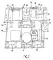
- FIG. 7is side-elevational view of a rear left-hand weldment of the present invention, as configured for use with an anti-sway bar;
- FIG. 8is an end view of the weldment shown in FIG. 7;
- FIG. 9is a top plan view of the weldment shown in FIGS. 7 and 8;
- FIG. 10is an exploded perspective view of a lower control arm constructed in accordance with the present invention.
- FIG. 11is a cross-sectional view of a bushing assembly of the control arm of the present invention taken along line 11 — 11 in FIG. 11A;
- FIG. 11Ais a top view of a bushing assembly of the control arm of the present invention.
- FIG. 12is an exploded perspective view of an anti-sway bar assembly made in accordance with the present invention.
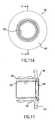
- FIG. 13is an end view of the spring guide bushing shown in FIG. 14, made in accordance with the present invention.
- FIG. 14is a cross-sectional view taken along line 14 — 14 in FIG. 13 and showing a bushing for a spring guide;
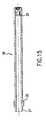
- FIG. 15is a longitudinal cross-section through a spring guide made in accordance with the present invention.
- FIG. 16is a perspective view of a suspension assembly in which electric motors are held between two side plates of the suspension assembly.
- FIG. 1shows the front portion of a vehicle and its suspension support in relation to a frame rail 2 of a vehicle.
- a left-hand or first side plate 10is mounted beneath a left-hand frame rail (not shown), and a right-hand or second side plate 12 is mounted beneath a right-hand frame rail 2 .
- a differential 15 with a differential drive connection 14is connected to each of the side plates 10 and 12 .
- the side plates 10 and 12are rigidly joined together by the lower plate 20 , bar 22 and differential 15 at the lower portions of the side plates 10 and 12 .
- This connection with lower plate 20 and bar 22form a direct and rigid connection between the two side plates 10 and 12 .
- the side plates shown in FIGS. 1 through 6are for a suspension that is not equipped with an anti-sway bar.
- first plate 10it is comprised of three main components which are welded together. Those components are: a longitudinally extending main plate member 51 ; a leading end plate 48 ; and a trailing end plate 50 .
- Longitudinally extending plate member 51is a single stamping that includes four sections: an upper vertical plate section 52 ; a horizontal plate section 54 , also referred to as a connecting plate; a lower vertical plate section 56 ; and a lower lip 58 .
- the upper vertical plate section 52 and the lower vertical plate section 56are in an off-set and generally parallel relationship, whereas upper vertical plate section 52 and lower vertical plate section 56 may be referred to as first and second mounting plates.
- a lifting lug 44may be welded to the bearing plate 47 for use in lifting the complete vehicle.
- the lower vertical plate section 56has an opening 70 so that a driveshaft, in the form of a halfshaft 16 , can extend from the differential 15 to the wheel end 18 (see FIG. 1 ).
- the elements of the suspension systemare connected to the outer portions of the first side plate 10 .
- the shock absorber 24extends from the bearing plate 42 to the lower control arm 32 .
- the suspension coil spring 26extends from the lower control arm 32 to the bearing plate 47 .
- a spring guide 28extends from the lower control arm 32 into the spring guide bushing 30 which is bolted to the coil spring bearing plate 47 .
- An upper control arm 34is connected by a ball joint 37 to an upper portion of the steering knuckle 41 .
- the upper and lower control arms 34 and 32are held in place by four control arm mounting assemblies 94 , an example of which is more clearly shown in FIG. 10 discussed below.
- control arm mounting assemblies for a left-hand side plate 10can best be seen in FIG. 4 wherein upper control arm attachment locations 68 and lower control arm attachment locations 66 are at upper and lower portions of the vertical mounting plate 56 .
- An ear 78is used to support various system lines, i.e., hoses and wires, etc., which lead to the wheel end 18 .
- a stiffening flange 60extends from the outer edge of the end plate 50 to provide the plate 50 with increased resistance to buckling.
- FIGS. 7, 8 and 9show a left-hand side plate 10 a for use with an anti-sway bar.
- the same reference numerals used to indicate portions of the non anti-sway bar front side plate 10are used for components which are the same.
- a coil spring bearing plate 47extends between an end plate 48 and a gusset 46 to define a pocket 39 for a coil spring (not shown in FIG. 7 ).
- the left-hand side plate 10 aincludes upper control arm mounting locations 68 and lower control arm mounting locations 66 .
- Gusset plates 40 and shock absorber bearing plate 42define a shock absorber pocket 38 .
- FIGS. 6 and 9further illustrate an opening 72 that allows for the coil spring and spring guide movement.
- FIG. 10is an exploded view of a lower control arm assembly.
- the lower control arm 32has two control arm mounting assemblies 94 , one of which is shown in exploded form on the left side of FIG. 10 .
- the control arm mounting assembly 94includes a pin 96 and two bushing assemblies 98 (more detail of which is shown in FIG. 11 ).
- the ends of the pin 96are clamped by the blocks 36 as the blocks 36 are attached to the lower vertical plate section 56 of a side plate.
- a thrust washer 108is disposed between each bushing assembly 98 and a block 36 .
- a screw 110 and washer 111are used to properly pre-load the bushing assembly 98 before installation.
- the lower control arm 32includes a spring mount 90 through which there extends a spring pivot pin 91 and a sleeve bearing 95 .
- a spring seat 84with a threaded hole 85 for receiving the spring guide 28 , straddles the spring mount 90 .
- a small dowel pin 89retains the spring pivot pin 91 in the spring seat 84 , and causes the spring seat 84 to rotate the spring pivot pin 91 within the sleeve bearing 95 .
- a pair of seals 93prevent contaminants from entering the sleeve bearing 95 within the spring mount 90 .
- FIG. 10also shows a ball joint assembly 82 , which is housed within a socket 80 on the outer end of the lower control arm 32 .
- FIG. 11is an enlarged cross-sectional view of the bushing assembly 98 which is part of the control arm mounting assembly 94 .
- the bushing assembly 98includes an inner sleeve bearing 106 , an intermediate sleeve 104 and an outer elastomeric sleeve 102 which has a flange 107 at one end and annular ribs and grooves on the outside surface thereof.
- a seal 100engages a shoulder formed on the outer edge of the intermediate sleeve 104 .
- the bushing assembly 98fits snugly into a bore formed at the inside end of each leg of the lower control arm 32 .
- a slot in each block 36 of a control arm mounting assemblyallows for easy removal of a pin 96 from the assembly 94 . Arranging the slots 97 so that they face down makes it harder for water and mud to flow into the pin/block joint.
- FIG. 12shows the anti-sway assembly which forms a part of the present invention.
- An anti-sway bar 112has a splined end 114 and extends through the opening 74 in the upper vertical plate section 52 of a rear side plate 10 a .
- the anti-sway bar 112is supported by a bushing 116 .
- the bushing 116is contained in a pocket 76 , the top portion of which is formed by a removable plate 124 .
- One end of the plate 124is inserted into a slot 77 formed in a gusset plate 40 , and the other end of the plate 124 is held in place by bolts.
- a pair of collars 118maintain the position of the anti-sway bar 112 in the bushing 116 .
- a pair of seals 119prevent contaminants from entering the bushing 116 .
- the splined end 114 of the anti-sway bar 112is engaged in and clamped by an end of the arm 120 .
- a vertical link 122connects an end of the arm 120 to the steering knuckle 41 .
- FIGS. 13 and 14show the spring guide bushing 30 which is attached to the coil spring bearing plate 47 on the front side plates 10 and 12 .
- the spring guide bushing 30includes a tapered bore or opening 31 through which a spring guide 28 extends. The taper allows the spring guide 28 to articulate slightly within the bushing 30 .
- Mounting ears 33facilitate the connection of the bushing 30 to the bearing plate 47 .
- the bushing 30is mounted in the orientation shown in FIG. 2 so that the narrower end of the tapered opening 31 is upward, i.e., the bushing 30 extends down into and through the opening in the bearing plate 47 .
- the rear springis stable enough by itself not to need a guide.
- the spring guide 28is shown in FIG. 15 .
- the spring guide 28has a threaded end 27 which threads into the threaded hole 85 in the spring seat 84 . (See FIG. 10.)
- a stop 35is welded to the body of the spring guide 28 to limit the threaded engagement of the treaded end 27 and the spring seat 84 .
- a drive socket 29is incorporated to facilitate the threaded engagement of the spring guide 28 into the spring seat 84 with a common wrench.
- the diameter of the spring guide 28is substantially smaller than inside diameter of the coil spring 26 through which it extends. The result is a non-contact spring guide.
- the spring guide 28is free to slide within the tapered opening 31 in the spring guide bushing 30 as the wheel of a vehicle moves up and down. The alignment of the spring seat 84 , however, is maintained so that buckling of the coil spring 26 is prevented, even in instances where there is a large compression of the spring as a result of relative movement of the wheel and the frame.
- FIG. 16is a perspective view of a suspension assembly in which two elecric motors 160 and 162 are mounted between side plates 10 b and 12 b , rather than a more traditional differential as shown in earlier described embodiments of the invention.
- the letter bis used in conjunction with the same reference numerals they correspond to as shown in FIGS. 1-3. This arrangement allows each of the motors to drive one half-shaft and one wheel. In the particular example shown in FIG. 16, the motors directly drive the half-shafts (not shown).
- the housings of the motors 160 and 162may be rigidly connected to one another.
- a 90 degree drive boxmay be inserted and the motors mounted in positions in which they are not disposed between the side plates, but are axially offset with respect to one another.
- the wheelsare held in aligned positions relative to the frame by stabilizing bars 164 and 166 , although the assembly shown is equally applicable to pairs of wheels which are steered wheels.
Landscapes
- Engineering & Computer Science (AREA)
- Mechanical Engineering (AREA)
- General Engineering & Computer Science (AREA)
- Chemical & Material Sciences (AREA)
- Combustion & Propulsion (AREA)
- Transportation (AREA)
- Vehicle Body Suspensions (AREA)
Abstract
Description
Claims (13)
Priority Applications (5)
| Application Number | Priority Date | Filing Date | Title |
|---|---|---|---|
| US09/635,791US6516914B1 (en) | 1993-04-14 | 2000-08-11 | Integrated vehicle suspension, axle and frame assembly |
| GB0415369AGB2400590B (en) | 2000-08-08 | 2001-08-08 | Vehicle suspension |
| GB0119374AGB2365829B (en) | 2000-08-08 | 2001-08-08 | Mounting assembly for a vehicle suspension arm |
| GB0415366AGB2400589B (en) | 2000-08-08 | 2001-08-08 | Vehicle suspension |
| GB0414193AGB2400588B (en) | 2000-08-08 | 2001-08-08 | Non-contact spring guide |
Applications Claiming Priority (6)
| Application Number | Priority Date | Filing Date | Title |
|---|---|---|---|
| US4662393A | 1993-04-14 | 1993-04-14 | |
| US08/421,995US5538274A (en) | 1993-04-14 | 1995-04-14 | Modular Independent coil spring suspension |
| US08/681,239US5820150A (en) | 1993-04-14 | 1996-07-22 | Independent suspensions for lowering height of vehicle frame |
| US12380498A | 1998-07-28 | 1998-07-28 | |
| US09/232,596US6105984A (en) | 1993-04-14 | 1999-01-19 | Independent coil spring suspension for driven wheels |
| US09/635,791US6516914B1 (en) | 1993-04-14 | 2000-08-11 | Integrated vehicle suspension, axle and frame assembly |
Related Parent Applications (1)
| Application Number | Title | Priority Date | Filing Date |
|---|---|---|---|
| US09/232,596Continuation-In-PartUS6105984A (en) | 1993-04-14 | 1999-01-19 | Independent coil spring suspension for driven wheels |
Publications (1)
| Publication Number | Publication Date |
|---|---|
| US6516914B1true US6516914B1 (en) | 2003-02-11 |
Family
ID=27534952
Family Applications (1)
| Application Number | Title | Priority Date | Filing Date |
|---|---|---|---|
| US09/635,791Expired - LifetimeUS6516914B1 (en) | 1993-04-14 | 2000-08-11 | Integrated vehicle suspension, axle and frame assembly |
Country Status (1)
| Country | Link |
|---|---|
| US (1) | US6516914B1 (en) |
Cited By (114)
| Publication number | Priority date | Publication date | Assignee | Title |
|---|---|---|---|---|
| US6764085B1 (en)* | 2000-08-09 | 2004-07-20 | Oshkosh Truck Corporation | Non-contact spring guide |
| US20040222031A1 (en)* | 2003-05-09 | 2004-11-11 | Norman Szalony | Independent rear suspension and support assembly |
| US20060055162A1 (en)* | 2001-11-27 | 2006-03-16 | Detlev Beckmann | Modular chassis for commercial vehicles |
| US20060065451A1 (en)* | 2004-09-28 | 2006-03-30 | Oshkosh Truck Corporation | Self-contained axle module |
| US20060070776A1 (en)* | 2004-09-28 | 2006-04-06 | Oshkosh Truck Corporation | Power takeoff for an electric vehicle |
| WO2006041441A1 (en)* | 2004-09-23 | 2006-04-20 | Axletech International, Inc. | Independent suspension with adjustable sub-frame |
| EP1627762A3 (en)* | 2004-08-17 | 2006-06-28 | AGCO GmbH | Agricultural tractor |
| US20060261570A1 (en)* | 2005-05-20 | 2006-11-23 | Arvinmeritor Technology, Llc | Six link independent suspension for a drive axle |
| US20070170682A1 (en)* | 2006-01-20 | 2007-07-26 | Takeshi Kinugasa | All terrain vehicle |
| EP1826100A3 (en)* | 2006-02-28 | 2008-05-21 | MAN Nutzfahrzeuge Österreich AG | Cross member arrangment for a utility vehicle with pneumatic suspension |
| US7380831B2 (en)* | 2000-12-28 | 2008-06-03 | Dana Heavy Vehicle Systems Group, Llc | Modular cast independent front suspension subframe |
| US20090174158A1 (en)* | 2005-02-28 | 2009-07-09 | Oshkosh Corporation | Suspension system |
| US7559403B2 (en) | 2006-04-05 | 2009-07-14 | Schmitz Geoffrey W | Modular, central frame, offset, dual control arm independent suspension and suspension retrofit |
| US20100116569A1 (en)* | 2004-09-28 | 2010-05-13 | Oshkosh Corporation | Self-contained axle module |
| AU2007242944B2 (en)* | 2007-01-26 | 2010-07-08 | Honda Motor Co., Ltd. | Suspension arm and cushion arm structure for vehicle |
| US20100307842A1 (en)* | 2009-06-09 | 2010-12-09 | International Truck Intellectual Property Company, Llc | Chassis Mounted Electric, Independent, Steering Axle of a Vehicle |
| US20110079978A1 (en)* | 2009-10-01 | 2011-04-07 | Oshkosh Corporation | Axle assembly |
| US8262112B1 (en) | 2011-07-08 | 2012-09-11 | Hendrickson Usa, L.L.C. | Vehicle suspension and improved method of assembly |
| US8302988B2 (en) | 2008-03-10 | 2012-11-06 | Hendrickson Usa, L.L.C. | Suspension assembly with tie-plate |
| USD672287S1 (en) | 2010-09-05 | 2012-12-11 | Hendrickson Usa, L.L.C. | Frame-hanger-to-frame-hanger tie-plate |
| USD672286S1 (en) | 2010-09-05 | 2012-12-11 | Hendrickson Usa, L.L.C. | Suspension assembly |
| EP2581240A1 (en)* | 2011-10-10 | 2013-04-17 | AxleTech International IP Holdings, LLC | Modular independent suspension and method of producing the same |
| US20130147145A1 (en)* | 2011-12-09 | 2013-06-13 | Hwashin Co. Ltd | Structure of vehicle subframe |
| EP2631094A2 (en) | 2012-02-23 | 2013-08-28 | ArvinMeritor Technology, LLC | Suspension module for a vehicle and a method of manufacture |
| US8596648B2 (en) | 2010-10-22 | 2013-12-03 | Oshkosh Corporation | Pump for vehicle suspension system |
| US8651222B2 (en)* | 2011-01-14 | 2014-02-18 | Bayerische Motoren Werke Aktiengesellschaft | Support of an axle transmission in the rear region of a passenger vehicle |
| USD699637S1 (en) | 2012-07-06 | 2014-02-18 | Hendrickson Usa, L.L.C. | Shear spring for a suspension |
| USD700113S1 (en) | 2012-07-06 | 2014-02-25 | Hendrickson Usa, L.L.C. | Suspension assembly |
| US8657315B2 (en) | 2011-07-08 | 2014-02-25 | Hendrickson Usa, L.L.C. | Vehicle suspension and improved method of assembly |
| US20140209397A1 (en)* | 2011-09-09 | 2014-07-31 | Zf Friedrichshafen Ag | Drive unit for an electric vehicle and method for defining a drive unit in an electric vehicle |
| US20140367951A1 (en)* | 2013-06-12 | 2014-12-18 | Arvinmeritor Technology, Llc | Suspension Module Having a Skidplate |
| US8925941B2 (en) | 2011-10-13 | 2015-01-06 | Axletech International Ip Holdings, Llc | Modular independent suspension and method of producing the same |
| US8991834B2 (en) | 2010-08-31 | 2015-03-31 | Oshkosh Defense, Llc | Gas spring assembly for a vehicle suspension system |
| US9004512B2 (en) | 2011-07-08 | 2015-04-14 | Hendrickson Usa, L.L.C. | Shear spring useful for vehicle suspension |
| US20150114735A1 (en)* | 2012-05-08 | 2015-04-30 | Ksm Castings Group Gmbh | Modular axle concept for a motor vehicle with electric drive |
| US9085212B2 (en) | 2013-03-15 | 2015-07-21 | Hendrickson Usa, L.L.C. | Vehicle suspension |
| US9127738B2 (en) | 2011-03-14 | 2015-09-08 | Oshkosh Defense, Llc | Damper assembly |
| US9150071B2 (en) | 2013-07-25 | 2015-10-06 | Hendrickson Usa, L.L.C. | Frame hanger for vehicle suspension |
| US9174686B1 (en) | 2012-02-22 | 2015-11-03 | Oshkosh Defense, Llc | Military vehicle |
| US9302129B1 (en) | 2014-11-24 | 2016-04-05 | Oshkosh Corporation | Turntable assembly for a fire apparatus |
| US9492695B2 (en) | 2014-11-24 | 2016-11-15 | Oshkosh Corporation | Pedestal and torque box assembly for a fire apparatus |
| US9504863B2 (en) | 2014-11-24 | 2016-11-29 | Oshkosh Corporation | Quint configuration fire apparatus |
| US9580962B2 (en) | 2014-11-24 | 2017-02-28 | Oshkosh Corporation | Outrigger assembly for a fire apparatus |
| US9579530B2 (en) | 2014-11-24 | 2017-02-28 | Oshkosh Corporation | Ladder assembly for a fire apparatus |
| US9580960B2 (en) | 2014-11-24 | 2017-02-28 | Oshkosh Corporation | Aerial ladder for a fire apparatus |
| US9651120B2 (en) | 2015-02-17 | 2017-05-16 | Oshkosh Corporation | Multi-mode electromechanical variable transmission |
| US9650032B2 (en) | 2015-02-17 | 2017-05-16 | Oshkosh Corporation | Multi-mode electromechanical variable transmission |
| US9656659B2 (en) | 2015-02-17 | 2017-05-23 | Oshkosh Corporation | Multi-mode electromechanical variable transmission |
| US9656640B1 (en) | 2012-03-26 | 2017-05-23 | Oshkosh Defense, Llc | Military vehicle |
| WO2017109009A1 (en)* | 2015-12-23 | 2017-06-29 | Technology Investments Limited | A rolling chassis assembly for a vehicle |
| US9809080B2 (en) | 2012-03-26 | 2017-11-07 | Oshkosh Defense, Llc | Position dependent damper for a vehicle suspension system |
| EP2668416A4 (en)* | 2011-01-28 | 2017-11-15 | Hendrickson USA, L.L.C. | Shock mount support assembly for heavy-duty vehicles |
| DE102016216219A1 (en) | 2016-08-29 | 2018-03-01 | Zf Friedrichshafen Ag | axle |
| USD814979S1 (en) | 2016-06-06 | 2018-04-10 | Axletech International Ip Holdings, Llc | Suspension axle |
| CN108238103A (en)* | 2016-12-27 | 2018-07-03 | 沃尔沃汽车公司 | Subframe component |
| CN108327525A (en)* | 2018-02-28 | 2018-07-27 | 北京汽车研究总院有限公司 | A kind of main reducing gear fixing bracket and vehicle |
| US10144389B2 (en) | 2015-04-20 | 2018-12-04 | Oshkosh Corporation | Response vehicle systems and methods |
| US10239403B2 (en) | 2014-03-03 | 2019-03-26 | Oshkosh Corporation | Concrete mixer vehicle having vertically-positioned CNG fuel tanks |
| US10286239B2 (en) | 2017-02-08 | 2019-05-14 | Oshkosh Corporation | Fire apparatus piercing tip ranging and alignment system |
| US10414067B2 (en) | 2016-06-17 | 2019-09-17 | Oshkosh Corporation | Concrete drum control, property prediction, and monitoring systems and methods |
| US10421350B2 (en) | 2015-10-20 | 2019-09-24 | Oshkosh Corporation | Inline electromechanical variable transmission system |
| US10525781B2 (en)* | 2018-01-22 | 2020-01-07 | Honda Motor Co., Ltd. | Mounting assembly for a suspension and wheel assembly of a vehicle, and vehicle including same |
| US10532772B2 (en)* | 2018-01-22 | 2020-01-14 | Honda Motor Co., Ltd. | Mounting assembly for a suspension and wheel assembly of a vehicle, and vehicle including same |
| US10578195B2 (en) | 2015-02-17 | 2020-03-03 | Oshkosh Corporation | Inline electromechanical variable transmission system |
| US10584775B2 (en) | 2015-02-17 | 2020-03-10 | Oshkosh Corporation | Inline electromechanical variable transmission system |
| USD907544S1 (en) | 2019-03-12 | 2021-01-12 | Oshkosh Corporation | Vehicle front bumper |
| US10934145B2 (en) | 2016-04-08 | 2021-03-02 | Oshkosh Corporation | Leveling system for lift device |
| US10953939B2 (en) | 2018-03-08 | 2021-03-23 | Oshkosh Corporation | Load span tag axle system |
| US10974724B1 (en) | 2019-10-11 | 2021-04-13 | Oshkosh Corporation | Operational modes for hybrid fire fighting vehicle |
| US10982736B2 (en) | 2015-02-17 | 2021-04-20 | Oshkosh Corporation | Multi-mode electromechanical variable transmission |
| US11001135B2 (en) | 2019-07-31 | 2021-05-11 | Oshkosh Corporation | Refuse vehicle with independently operational accessory system |
| US11001440B2 (en) | 2019-05-03 | 2021-05-11 | Oshkosh Corporation | Carry can for refuse vehicle |
| US11097617B2 (en) | 2019-05-03 | 2021-08-24 | Oshkosh Corporation | Auxiliary power system for electric refuse vehicle |
| US11110977B2 (en) | 2017-12-19 | 2021-09-07 | Oshkosh Corporation | Off-road vehicle |
| US11137053B2 (en) | 2019-07-15 | 2021-10-05 | Oshkosh Corporation | Three planetary inline emivt |
| US11136187B1 (en) | 2020-09-28 | 2021-10-05 | Oshkosh Corporation | Control system for a refuse vehicle |
| US11148880B1 (en) | 2020-04-17 | 2021-10-19 | Oshkosh Corporation | Refuse vehicle control systems |
| US11161415B1 (en) | 2020-09-28 | 2021-11-02 | Oshkosh Corporation | System and method for electronic power take-off controls |
| US20220024291A1 (en)* | 2017-07-28 | 2022-01-27 | Dana Heavy Vehicle Systems Group, Llc | Cradle assembly for an electric axle assembly |
| US11254498B1 (en) | 2020-09-28 | 2022-02-22 | Oshkosh Corporation | Electric power take-off for a refuse vehicle |
| US11351825B2 (en) | 2019-06-10 | 2022-06-07 | Oshkosh Corporation | Stabilization system for a vehicle |
| US11376990B1 (en) | 2021-08-13 | 2022-07-05 | Oshkosh Defense, Llc | Electrified military vehicle |
| US20220242183A1 (en)* | 2021-02-03 | 2022-08-04 | GM Global Technology Operations LLC | Multi-tiered body frame integral structure for off road vehicles |
| US11433757B2 (en)* | 2019-08-01 | 2022-09-06 | Autonomous Tractor Corporation | Electric wheel drive system and hybrid vehicle |
| US11447020B2 (en) | 2019-04-05 | 2022-09-20 | Oshkosh Corporation | Battery management systems and methods |
| US11465838B2 (en) | 2020-04-17 | 2022-10-11 | Oshkosh Corporation | Lighting system for a refuse vehicle |
| US11465698B2 (en) | 2020-03-09 | 2022-10-11 | Oshkosh Corporation | Stabilizer bar for a load span tag axle |
| US11472308B2 (en) | 2019-04-05 | 2022-10-18 | Oshkosh Corporation | Electric concrete vehicle systems and methods |
| USD966958S1 (en) | 2011-09-27 | 2022-10-18 | Oshkosh Corporation | Grille element |
| US11498409B1 (en) | 2021-08-13 | 2022-11-15 | Oshkosh Defense, Llc | Electrified military vehicle |
| US11521385B2 (en) | 2018-04-23 | 2022-12-06 | Oshkosh Corporation | Refuse vehicle control system |
| US11597638B2 (en) | 2019-04-05 | 2023-03-07 | Oshkosh Corporation | Oscillating axle for lift device |
| US11630201B2 (en) | 2020-04-17 | 2023-04-18 | Oshkosh Corporation | Refuse vehicle with spatial awareness |
| US11701959B2 (en) | 2015-02-17 | 2023-07-18 | Oshkosh Corporation | Inline electromechanical variable transmission system |
| US11899460B2 (en) | 2020-04-17 | 2024-02-13 | Oshkosh Corporation | Automated alignment and dumping of refuse cans |
| US11922736B2 (en) | 2020-04-17 | 2024-03-05 | Oshkosh Corporation | Systems and methods for automatic system checks |
| US12007793B2 (en) | 2020-04-17 | 2024-06-11 | Oshkosh Corporation | Denial of service systems and methods |
| US12030479B1 (en) | 2021-08-13 | 2024-07-09 | Oshkosh Defense, Llc | Prioritized charging of an energy storage system of a military vehicle |
| US12049136B2 (en) | 2019-07-31 | 2024-07-30 | Oshkosh Corporation | Refuse vehicle with range extension |
| US12060053B1 (en) | 2021-08-13 | 2024-08-13 | Oshkosh Defense, Llc | Military vehicle with control modes |
| US12078231B2 (en) | 2015-02-17 | 2024-09-03 | Oshkosh Corporation | Inline electromechanical variable transmission system |
| US12083995B1 (en) | 2021-08-13 | 2024-09-10 | Oshkosh Defense, Llc | Power export system for a military vehicle |
| US12130122B1 (en) | 2021-08-13 | 2024-10-29 | Oshkosh Defense, Llc | Military vehicle with battery armor |
| US12162679B2 (en) | 2020-09-28 | 2024-12-10 | Oshkosh Corporation | Control system for a refuse vehicle |
| US12231824B2 (en) | 2020-04-17 | 2025-02-18 | Oshkosh Corporation | Systems and methods for spatial awareness of a refuse vehicle |
| US12234135B2 (en) | 2014-11-24 | 2025-02-25 | Oshkosh Corporation | Fire apparatus |
| US12311754B1 (en) | 2021-08-13 | 2025-05-27 | Oshkosh Defense, Llc | Power export system for a military vehicle |
| US12319160B1 (en) | 2021-08-13 | 2025-06-03 | Oshkosh Defense, Llc | Convoy operations for electrified military vehicles |
| US12335807B2 (en) | 2020-04-17 | 2025-06-17 | Oshkosh Corporation | Active truck tracking and alerts for residential refuse can collection |
| US12351034B2 (en) | 2019-08-01 | 2025-07-08 | Autonomous Tractor Corporation | Directly supported electric drive wheel system and hybrid vehicle |
| US12351028B1 (en) | 2021-08-13 | 2025-07-08 | Oshkosh Defense, Llc | Military vehicle with modular battery units |
| US12358361B1 (en) | 2021-08-13 | 2025-07-15 | Oshkosh Defense, Llc | Electrified military vehicle with electric weaponry support system |
| US12427820B2 (en)* | 2024-02-01 | 2025-09-30 | Toyota Jidosha Kabushiki Kaisha | Attachment structure for upper arm of double wishbone shock absorber |
| US12441177B1 (en) | 2024-03-11 | 2025-10-14 | Oshkosh Defense, Llc | Electrified military vehicle |
Citations (7)
| Publication number | Priority date | Publication date | Assignee | Title |
|---|---|---|---|---|
| US2278303A (en)* | 1941-04-05 | 1942-03-31 | Theodore L W Matter | Wheel suspension for motor vehicles |
| US3243007A (en)* | 1961-05-09 | 1966-03-29 | Koehring Co | Wheel suspension for driven steerable wheels |
| US3441289A (en)* | 1966-09-02 | 1969-04-29 | Chrysler Corp | Drop out front cross member |
| US4813704A (en)* | 1988-06-20 | 1989-03-21 | Chrysler Motors Corporation | Dual strut wheel suspension |
| US4848789A (en)* | 1987-04-07 | 1989-07-18 | Technology Investments Limited | Vehicle chassis tranverse structural member |
| US4943081A (en)* | 1989-02-10 | 1990-07-24 | Rancho Industries, Inc. | Vehicle suspension assembly |
| US5915727A (en)* | 1996-05-31 | 1999-06-29 | Dana Corporation | Mounting structure for vehicle frame assembly |
- 2000
- 2000-08-11USUS09/635,791patent/US6516914B1/ennot_activeExpired - Lifetime
Patent Citations (7)
| Publication number | Priority date | Publication date | Assignee | Title |
|---|---|---|---|---|
| US2278303A (en)* | 1941-04-05 | 1942-03-31 | Theodore L W Matter | Wheel suspension for motor vehicles |
| US3243007A (en)* | 1961-05-09 | 1966-03-29 | Koehring Co | Wheel suspension for driven steerable wheels |
| US3441289A (en)* | 1966-09-02 | 1969-04-29 | Chrysler Corp | Drop out front cross member |
| US4848789A (en)* | 1987-04-07 | 1989-07-18 | Technology Investments Limited | Vehicle chassis tranverse structural member |
| US4813704A (en)* | 1988-06-20 | 1989-03-21 | Chrysler Motors Corporation | Dual strut wheel suspension |
| US4943081A (en)* | 1989-02-10 | 1990-07-24 | Rancho Industries, Inc. | Vehicle suspension assembly |
| US5915727A (en)* | 1996-05-31 | 1999-06-29 | Dana Corporation | Mounting structure for vehicle frame assembly |
Cited By (298)
| Publication number | Priority date | Publication date | Assignee | Title |
|---|---|---|---|---|
| US20050001400A1 (en)* | 2000-08-09 | 2005-01-06 | Oshkosh Truck Corporation | Mounting assembly for a vehicle suspension arm |
| US6976688B2 (en) | 2000-08-09 | 2005-12-20 | Oshkosh Truck Corporation | Mounting assembly for a vehicle suspension arm |
| US6764085B1 (en)* | 2000-08-09 | 2004-07-20 | Oshkosh Truck Corporation | Non-contact spring guide |
| US7380831B2 (en)* | 2000-12-28 | 2008-06-03 | Dana Heavy Vehicle Systems Group, Llc | Modular cast independent front suspension subframe |
| US7207600B2 (en)* | 2001-11-27 | 2007-04-24 | Daimlerchrysler Ag | Modular chassis for commercial vehicles |
| US20060055162A1 (en)* | 2001-11-27 | 2006-03-16 | Detlev Beckmann | Modular chassis for commercial vehicles |
| US20040222031A1 (en)* | 2003-05-09 | 2004-11-11 | Norman Szalony | Independent rear suspension and support assembly |
| GB2417226B (en)* | 2004-08-17 | 2008-09-17 | Agco Gmbh & Co | Agricultural tractor |
| EP1627762A3 (en)* | 2004-08-17 | 2006-06-28 | AGCO GmbH | Agricultural tractor |
| WO2006041441A1 (en)* | 2004-09-23 | 2006-04-20 | Axletech International, Inc. | Independent suspension with adjustable sub-frame |
| US20080258417A1 (en)* | 2004-09-23 | 2008-10-23 | Gerard Cordier | Independent Suspension with Adjustable Sub-Frame |
| US20110221154A1 (en)* | 2004-09-23 | 2011-09-15 | Axletech International Ip Holdings, Llc | Independent Suspension With Adjustable Sub-Frame |
| US7850181B2 (en) | 2004-09-23 | 2010-12-14 | Axletech International Ip Holdings, Llc | Independent suspension with adjustable sub-frame |
| US8096567B2 (en) | 2004-09-23 | 2012-01-17 | Axletech International Ip Holdings, Llc | Independent suspension with adjustable sub-frame |
| US7448460B2 (en) | 2004-09-28 | 2008-11-11 | Oshkosh Corporation | Power takeoff for an electric vehicle |
| US20060065451A1 (en)* | 2004-09-28 | 2006-03-30 | Oshkosh Truck Corporation | Self-contained axle module |
| US20060070776A1 (en)* | 2004-09-28 | 2006-04-06 | Oshkosh Truck Corporation | Power takeoff for an electric vehicle |
| US7931103B2 (en) | 2004-09-28 | 2011-04-26 | Oshkosh Corporation | Electric vehicle with power takeoff |
| US7357203B2 (en) | 2004-09-28 | 2008-04-15 | Oshkosh Truck Corporation | Self-contained axle module |
| US8561735B2 (en) | 2004-09-28 | 2013-10-22 | Oshkosh Corporation | Self-contained axle module |
| US20080150350A1 (en)* | 2004-09-28 | 2008-06-26 | Oshkosh Corporation | Self-contained axle module |
| US20100116569A1 (en)* | 2004-09-28 | 2010-05-13 | Oshkosh Corporation | Self-contained axle module |
| US20090174158A1 (en)* | 2005-02-28 | 2009-07-09 | Oshkosh Corporation | Suspension system |
| US7819411B2 (en)* | 2005-05-20 | 2010-10-26 | Arvinmeritor Technology, Llc | Six link independent suspension for a drive axle |
| US20060261570A1 (en)* | 2005-05-20 | 2006-11-23 | Arvinmeritor Technology, Llc | Six link independent suspension for a drive axle |
| US7661689B2 (en)* | 2006-01-20 | 2010-02-16 | Yamaha Hatsudoki Kabushiki Kaisha | All terrain vehicle |
| US20070170682A1 (en)* | 2006-01-20 | 2007-07-26 | Takeshi Kinugasa | All terrain vehicle |
| EP1826100A3 (en)* | 2006-02-28 | 2008-05-21 | MAN Nutzfahrzeuge Österreich AG | Cross member arrangment for a utility vehicle with pneumatic suspension |
| US7559403B2 (en) | 2006-04-05 | 2009-07-14 | Schmitz Geoffrey W | Modular, central frame, offset, dual control arm independent suspension and suspension retrofit |
| AU2007242944B2 (en)* | 2007-01-26 | 2010-07-08 | Honda Motor Co., Ltd. | Suspension arm and cushion arm structure for vehicle |
| US8302988B2 (en) | 2008-03-10 | 2012-11-06 | Hendrickson Usa, L.L.C. | Suspension assembly with tie-plate |
| US8720937B2 (en) | 2008-03-10 | 2014-05-13 | Hendrickson Usa, L.L.C. | Load cushion for vehicle suspension |
| US20100307842A1 (en)* | 2009-06-09 | 2010-12-09 | International Truck Intellectual Property Company, Llc | Chassis Mounted Electric, Independent, Steering Axle of a Vehicle |
| US7980350B2 (en)* | 2009-06-09 | 2011-07-19 | Navistar Canada, Inc. | Chassis mounted electric, independent, steering axle of a vehicle |
| US20110169240A1 (en)* | 2009-10-01 | 2011-07-14 | Oshkosh Corporation | Axle assembly |
| US20110079978A1 (en)* | 2009-10-01 | 2011-04-07 | Oshkosh Corporation | Axle assembly |
| US8402878B2 (en) | 2009-10-01 | 2013-03-26 | Oshkosh Corporation | Axle assembly |
| US9688112B2 (en) | 2010-08-31 | 2017-06-27 | Oshkosh Defense, Llc | Gas spring assembly for a vehicle suspension system |
| US12115826B2 (en) | 2010-08-31 | 2024-10-15 | Oshkosh Defense, Llc | Gas spring assembly for a vehicle suspension system |
| US10421332B2 (en) | 2010-08-31 | 2019-09-24 | Oshkosh Defense, Llc | Gas spring assembly for a vehicle suspension system |
| US8991834B2 (en) | 2010-08-31 | 2015-03-31 | Oshkosh Defense, Llc | Gas spring assembly for a vehicle suspension system |
| US11225119B2 (en) | 2010-08-31 | 2022-01-18 | Oshkosh Defense, Llc | Gas spring assembly for a vehicle suspension system |
| US11225120B2 (en) | 2010-08-31 | 2022-01-18 | Oshkosh Defense, Llc | Gas spring assembly for a vehicle suspension system |
| USD672287S1 (en) | 2010-09-05 | 2012-12-11 | Hendrickson Usa, L.L.C. | Frame-hanger-to-frame-hanger tie-plate |
| USD672286S1 (en) | 2010-09-05 | 2012-12-11 | Hendrickson Usa, L.L.C. | Suspension assembly |
| US8596648B2 (en) | 2010-10-22 | 2013-12-03 | Oshkosh Corporation | Pump for vehicle suspension system |
| US9581153B2 (en) | 2010-10-22 | 2017-02-28 | Oshkosh Corporation | Pump for vehicle suspension system |
| US8821130B2 (en) | 2010-10-22 | 2014-09-02 | Oshkosh Corporation | Pump for vehicle suspension system |
| US8651222B2 (en)* | 2011-01-14 | 2014-02-18 | Bayerische Motoren Werke Aktiengesellschaft | Support of an axle transmission in the rear region of a passenger vehicle |
| EP2668416A4 (en)* | 2011-01-28 | 2017-11-15 | Hendrickson USA, L.L.C. | Shock mount support assembly for heavy-duty vehicles |
| US11378148B2 (en) | 2011-03-14 | 2022-07-05 | Oshkosh Defense, Llc | Damper assembly |
| US11209067B2 (en) | 2011-03-14 | 2021-12-28 | Oshkosh Defense, Llc | Damper assembly |
| US9765841B2 (en) | 2011-03-14 | 2017-09-19 | Oshkosh Defense, Llc | Damper assembly |
| US10422403B2 (en) | 2011-03-14 | 2019-09-24 | Oshkosh Defense, Llc | Damper assembly |
| US9127738B2 (en) | 2011-03-14 | 2015-09-08 | Oshkosh Defense, Llc | Damper assembly |
| US8276927B1 (en) | 2011-07-08 | 2012-10-02 | Hendrickson Usa, L.L.C. | Vehicle suspension and improved method of assembly |
| US9004512B2 (en) | 2011-07-08 | 2015-04-14 | Hendrickson Usa, L.L.C. | Shear spring useful for vehicle suspension |
| US8262112B1 (en) | 2011-07-08 | 2012-09-11 | Hendrickson Usa, L.L.C. | Vehicle suspension and improved method of assembly |
| US8342566B1 (en) | 2011-07-08 | 2013-01-01 | Hendrickson Usa, L.L.C. | Shear spring for vehicle suspension |
| US8657315B2 (en) | 2011-07-08 | 2014-02-25 | Hendrickson Usa, L.L.C. | Vehicle suspension and improved method of assembly |
| US20140209397A1 (en)* | 2011-09-09 | 2014-07-31 | Zf Friedrichshafen Ag | Drive unit for an electric vehicle and method for defining a drive unit in an electric vehicle |
| USD843281S1 (en) | 2011-09-27 | 2019-03-19 | Oshkosh Corporation | Vehicle hood |
| USD966958S1 (en) | 2011-09-27 | 2022-10-18 | Oshkosh Corporation | Grille element |
| USD1008127S1 (en) | 2011-09-27 | 2023-12-19 | Oshkosh Corporation | Vehicle fender |
| EP2581240A1 (en)* | 2011-10-10 | 2013-04-17 | AxleTech International IP Holdings, LLC | Modular independent suspension and method of producing the same |
| US8925941B2 (en) | 2011-10-13 | 2015-01-06 | Axletech International Ip Holdings, Llc | Modular independent suspension and method of producing the same |
| US20130147145A1 (en)* | 2011-12-09 | 2013-06-13 | Hwashin Co. Ltd | Structure of vehicle subframe |
| US8616568B2 (en)* | 2011-12-09 | 2013-12-31 | Hyundai Motor Company | Structure of vehicle subframe |
| US9707869B1 (en) | 2012-02-22 | 2017-07-18 | Oshkosh Defense, Llc | Military vehicle |
| US9174686B1 (en) | 2012-02-22 | 2015-11-03 | Oshkosh Defense, Llc | Military vehicle |
| US8579308B2 (en) | 2012-02-23 | 2013-11-12 | Arvinmeritor Technology, Llc | Suspension module for a vehicle and a method of manufacture |
| EP2631094A2 (en) | 2012-02-23 | 2013-08-28 | ArvinMeritor Technology, LLC | Suspension module for a vehicle and a method of manufacture |
| USD856860S1 (en) | 2012-03-26 | 2019-08-20 | Oshkosh Corporation | Grille element |
| US10434995B2 (en) | 2012-03-26 | 2019-10-08 | Oshkosh Defense, Llc | Military vehicle |
| US11135890B2 (en) | 2012-03-26 | 2021-10-05 | Oshkosh Defense, Llc | Position dependent damper for a vehicle suspension system |
| US12420752B1 (en) | 2012-03-26 | 2025-09-23 | Oshkosh Defense, Llc | Military vehicle |
| US9656640B1 (en) | 2012-03-26 | 2017-05-23 | Oshkosh Defense, Llc | Military vehicle |
| USD929913S1 (en) | 2012-03-26 | 2021-09-07 | Oshkosh Corporation | Grille element |
| US11260835B2 (en) | 2012-03-26 | 2022-03-01 | Oshkosh Defense, Llc | Military vehicle |
| US11273805B2 (en) | 2012-03-26 | 2022-03-15 | Oshkosh Defense, Llc | Military vehicle |
| US12384337B1 (en) | 2012-03-26 | 2025-08-12 | Oshkosh Defense, Llc | Military vehicle |
| US11273804B2 (en) | 2012-03-26 | 2022-03-15 | Oshkosh Defense, Llc | Military vehicle |
| USD949069S1 (en) | 2012-03-26 | 2022-04-19 | Oshkosh Corporation | Vehicle hood |
| US9809080B2 (en) | 2012-03-26 | 2017-11-07 | Oshkosh Defense, Llc | Position dependent damper for a vehicle suspension system |
| US11332104B2 (en) | 2012-03-26 | 2022-05-17 | Oshkosh Defense, Llc | Military vehicle |
| US11338781B2 (en) | 2012-03-26 | 2022-05-24 | Oshkosh Defense, Llc | Military vehicle |
| US11364882B2 (en) | 2012-03-26 | 2022-06-21 | Oshkosh Defense, Llc | Military vehicle |
| US12377824B1 (en) | 2012-03-26 | 2025-08-05 | Oshkosh Defense, Llc | Military vehicle |
| US12370860B1 (en) | 2012-03-26 | 2025-07-29 | Oshkosh Defense, Llc | Position dependent damper |
| USD1085958S1 (en) | 2012-03-26 | 2025-07-29 | Oshkosh Corporation | Grille element |
| US11535212B2 (en) | 2012-03-26 | 2022-12-27 | Oshkosh Defense, Llc | Military vehicle |
| US12351149B1 (en) | 2012-03-26 | 2025-07-08 | Oshkosh Defense, Llc | Military vehicle |
| USD1076745S1 (en) | 2012-03-26 | 2025-05-27 | Oshkosh Corporation | Set of vehicle doors |
| US11541851B2 (en) | 2012-03-26 | 2023-01-03 | Oshkosh Defense, Llc | Military vehicle |
| USD1064940S1 (en) | 2012-03-26 | 2025-03-04 | Oshkosh Corporation | Grille element |
| US11685219B2 (en) | 2012-03-26 | 2023-06-27 | Oshkosh Defense, Llc | Position dependent damper for a vehicle suspension system |
| US11840208B2 (en) | 2012-03-26 | 2023-12-12 | Oshkosh Defense, Llc | Military vehicle |
| USD909934S1 (en) | 2012-03-26 | 2021-02-09 | Oshkosh Corporation | Vehicle hood |
| US11866018B2 (en) | 2012-03-26 | 2024-01-09 | Oshkosh Defense, Llc | Military vehicle |
| US12054027B1 (en) | 2012-03-26 | 2024-08-06 | Oshkosh Defense, Llc | Vehicle with a position dependent damper |
| US10369860B2 (en) | 2012-03-26 | 2019-08-06 | Oshkosh Corporation | Position dependent damper for a vehicle suspension system |
| USD930862S1 (en) | 2012-03-26 | 2021-09-14 | Oshkosh Corporation | Vehicle hood |
| US12036966B2 (en) | 2012-03-26 | 2024-07-16 | Oshkosh Defense, Llc | Military vehicle |
| USD898632S1 (en) | 2012-03-26 | 2020-10-13 | Oshkosh Corporation | Grille element |
| US12036967B2 (en) | 2012-03-26 | 2024-07-16 | Oshkosh Defense, Llc | Military vehicle |
| USD892002S1 (en) | 2012-03-26 | 2020-08-04 | Oshkosh Corporation | Grille element |
| US12434672B1 (en) | 2012-03-26 | 2025-10-07 | Oshkosh Defense, Llc | Military vehicle |
| USD863144S1 (en) | 2012-03-26 | 2019-10-15 | Oshkosh Corporation | Grille element |
| USD871283S1 (en) | 2012-03-26 | 2019-12-31 | Oshkosh Corporation | Vehicle hood |
| USD888629S1 (en) | 2012-03-26 | 2020-06-30 | Oshkosh Corporation | Vehicle hood |
| US11958457B2 (en) | 2012-03-26 | 2024-04-16 | Oshkosh Defense, Llc | Military vehicle |
| US11878669B2 (en) | 2012-03-26 | 2024-01-23 | Oshkosh Defense, Llc | Military vehicle |
| US11866019B2 (en) | 2012-03-26 | 2024-01-09 | Oshkosh Defense, Llc | Military vehicle |
| US9669873B2 (en)* | 2012-05-08 | 2017-06-06 | Ksm Castings Group Gmbh | Modular axle concept for a motor vehicle with electric drive |
| US20150114735A1 (en)* | 2012-05-08 | 2015-04-30 | Ksm Castings Group Gmbh | Modular axle concept for a motor vehicle with electric drive |
| USD699637S1 (en) | 2012-07-06 | 2014-02-18 | Hendrickson Usa, L.L.C. | Shear spring for a suspension |
| USD700113S1 (en) | 2012-07-06 | 2014-02-25 | Hendrickson Usa, L.L.C. | Suspension assembly |
| US9085212B2 (en) | 2013-03-15 | 2015-07-21 | Hendrickson Usa, L.L.C. | Vehicle suspension |
| US9242524B2 (en)* | 2013-03-15 | 2016-01-26 | Hendrickson Usa, L.L.C. | Vehicle suspension |
| US9221496B2 (en)* | 2013-06-12 | 2015-12-29 | Arvinmeritor Technology, Llc | Suspension module having a skidplate |
| US20140367951A1 (en)* | 2013-06-12 | 2014-12-18 | Arvinmeritor Technology, Llc | Suspension Module Having a Skidplate |
| US9150071B2 (en) | 2013-07-25 | 2015-10-06 | Hendrickson Usa, L.L.C. | Frame hanger for vehicle suspension |
| US10239403B2 (en) | 2014-03-03 | 2019-03-26 | Oshkosh Corporation | Concrete mixer vehicle having vertically-positioned CNG fuel tanks |
| US9492695B2 (en) | 2014-11-24 | 2016-11-15 | Oshkosh Corporation | Pedestal and torque box assembly for a fire apparatus |
| US9579530B2 (en) | 2014-11-24 | 2017-02-28 | Oshkosh Corporation | Ladder assembly for a fire apparatus |
| US12263365B2 (en) | 2014-11-24 | 2025-04-01 | Oshkosh Corporation | Quint configuration fire apparatus |
| US12378102B2 (en) | 2014-11-24 | 2025-08-05 | Oshkosh Corporation | Support structure for a ladder assembly of a fire apparatus |
| US9504863B2 (en) | 2014-11-24 | 2016-11-29 | Oshkosh Corporation | Quint configuration fire apparatus |
| US9814915B2 (en) | 2014-11-24 | 2017-11-14 | Oshkosh Corporation | Quint configuration fire apparatus |
| US9580962B2 (en) | 2014-11-24 | 2017-02-28 | Oshkosh Corporation | Outrigger assembly for a fire apparatus |
| US12365571B2 (en) | 2014-11-24 | 2025-07-22 | Oshkosh Corporation | Ladder and turntable assembly for a fire apparatus |
| US9580960B2 (en) | 2014-11-24 | 2017-02-28 | Oshkosh Corporation | Aerial ladder for a fire apparatus |
| US9677334B2 (en) | 2014-11-24 | 2017-06-13 | Oshkosh Corporation | Aerial ladder for a fire apparatus |
| US12234135B2 (en) | 2014-11-24 | 2025-02-25 | Oshkosh Corporation | Fire apparatus |
| US11813488B2 (en) | 2014-11-24 | 2023-11-14 | Oshkosh Corporation | Quint configuration fire apparatus |
| US11975223B2 (en) | 2014-11-24 | 2024-05-07 | Oshkosh Corporation | Quint configuration fire apparatus |
| US9302129B1 (en) | 2014-11-24 | 2016-04-05 | Oshkosh Corporation | Turntable assembly for a fire apparatus |
| US9597536B1 (en) | 2014-11-24 | 2017-03-21 | Oshkosh Corporation | Quint configuration fire apparatus |
| US9650032B2 (en) | 2015-02-17 | 2017-05-16 | Oshkosh Corporation | Multi-mode electromechanical variable transmission |
| US10974713B2 (en) | 2015-02-17 | 2021-04-13 | Oshkosh Corporation | Multi-mode electromechanical variable transmission |
| US9651120B2 (en) | 2015-02-17 | 2017-05-16 | Oshkosh Corporation | Multi-mode electromechanical variable transmission |
| US10160438B2 (en) | 2015-02-17 | 2018-12-25 | Oshkosh Corporation | Multi-mode electromechanical variable transmission |
| US10267390B2 (en) | 2015-02-17 | 2019-04-23 | Oshkosh Corporation | Multi-mode electromechanical variable transmission |
| US9656659B2 (en) | 2015-02-17 | 2017-05-23 | Oshkosh Corporation | Multi-mode electromechanical variable transmission |
| US9970515B2 (en) | 2015-02-17 | 2018-05-15 | Oshkosh Corporation | Multi-mode electromechanical variable transmission |
| US10578195B2 (en) | 2015-02-17 | 2020-03-03 | Oshkosh Corporation | Inline electromechanical variable transmission system |
| US12078231B2 (en) | 2015-02-17 | 2024-09-03 | Oshkosh Corporation | Inline electromechanical variable transmission system |
| US10967728B2 (en) | 2015-02-17 | 2021-04-06 | Oshkosh Corporation | Multi-mode electromechanical variable transmission |
| US11701959B2 (en) | 2015-02-17 | 2023-07-18 | Oshkosh Corporation | Inline electromechanical variable transmission system |
| US12228195B2 (en) | 2015-02-17 | 2025-02-18 | Oshkosh Corporation | Driveline for electrified vehicle |
| US11009104B2 (en) | 2015-02-17 | 2021-05-18 | Oshkosh Corporation | Inline electromechanical variable transmission system |
| US10584775B2 (en) | 2015-02-17 | 2020-03-10 | Oshkosh Corporation | Inline electromechanical variable transmission system |
| US10029555B2 (en) | 2015-02-17 | 2018-07-24 | Oshkosh Corporation | Multi-mode electromechanical variable transmission |
| US9908520B2 (en) | 2015-02-17 | 2018-03-06 | Oshkosh Corporation | Multi-mode electromechanical variable transmission |
| US10989279B2 (en) | 2015-02-17 | 2021-04-27 | Oshkosh Corporation | Multi-mode electromechanical variable transmission |
| US10982736B2 (en) | 2015-02-17 | 2021-04-20 | Oshkosh Corporation | Multi-mode electromechanical variable transmission |
| US10935112B2 (en) | 2015-02-17 | 2021-03-02 | Oshkosh Corporation | Inline electromechanical variable transmission system |
| US12384328B2 (en) | 2015-04-20 | 2025-08-12 | Oshkosh Corporation | Response vehicle systems and methods |
| US10144389B2 (en) | 2015-04-20 | 2018-12-04 | Oshkosh Corporation | Response vehicle systems and methods |
| US10981538B2 (en) | 2015-04-20 | 2021-04-20 | Oshkosh Corporation | Response vehicle systems and methods |
| US12227144B2 (en) | 2015-04-20 | 2025-02-18 | Oshkosh Corporation | Automatic vehicle braking in response to operator egress |
| US11577689B2 (en) | 2015-04-20 | 2023-02-14 | Oshkosh Corporation | Response vehicle systems and methods |
| US12049190B2 (en) | 2015-04-20 | 2024-07-30 | Oshkosh Corporation | Response vehicle systems and methods |
| US11007860B2 (en) | 2015-10-20 | 2021-05-18 | Oshkosh Corporation | Inline electromechanical variable transmission system |
| US10421350B2 (en) | 2015-10-20 | 2019-09-24 | Oshkosh Corporation | Inline electromechanical variable transmission system |
| WO2017109009A1 (en)* | 2015-12-23 | 2017-06-29 | Technology Investments Limited | A rolling chassis assembly for a vehicle |
| US11565920B2 (en) | 2016-04-08 | 2023-01-31 | Oshkosh Corporation | Leveling system for lift device |
| US10934145B2 (en) | 2016-04-08 | 2021-03-02 | Oshkosh Corporation | Leveling system for lift device |
| US12091298B2 (en) | 2016-04-08 | 2024-09-17 | Oshkosh Corporation | Leveling system for lift device |
| US11111120B2 (en) | 2016-04-08 | 2021-09-07 | Oshkosh Corporation | Leveling system for lift device |
| US11679967B2 (en) | 2016-04-08 | 2023-06-20 | Oshkosh Corporation | Leveling system for lift device |
| USD814979S1 (en) | 2016-06-06 | 2018-04-10 | Axletech International Ip Holdings, Llc | Suspension axle |
| US11858172B2 (en) | 2016-06-17 | 2024-01-02 | Oshkosh Corporation | Concrete drum control, property prediction, and monitoring systems and methods |
| US12240147B2 (en) | 2016-06-17 | 2025-03-04 | Oshkosh Corporation | Concrete drum control, property prediction, and monitoring systems and methods |
| US10414067B2 (en) | 2016-06-17 | 2019-09-17 | Oshkosh Corporation | Concrete drum control, property prediction, and monitoring systems and methods |
| US11806896B2 (en) | 2016-06-17 | 2023-11-07 | Oshkosh Corporation | Concrete drum control, property prediction, and monitoring systems and methods |
| US10987829B2 (en) | 2016-06-17 | 2021-04-27 | Oshkosh Corporation | Concrete drum control, property prediction, and monitoring systems and methods |
| US11413787B2 (en) | 2016-06-17 | 2022-08-16 | Oshkosh Corporation | Concrete drum control, property prediction, and monitoring systems and methods |
| US11992970B2 (en) | 2016-06-17 | 2024-05-28 | Oshkosh Corporation | Concrete drum control, property prediction, and monitoring system and methods |
| DE102016216219A1 (en) | 2016-08-29 | 2018-03-01 | Zf Friedrichshafen Ag | axle |
| EP3342614A1 (en)* | 2016-12-27 | 2018-07-04 | Volvo Car Corporation | Subframe assembly |
| CN108238103A (en)* | 2016-12-27 | 2018-07-03 | 沃尔沃汽车公司 | Subframe component |
| US11524193B2 (en) | 2017-02-08 | 2022-12-13 | Oshkosh Corporation | Fire apparatus piercing tip ranging and alignment system |
| US10286239B2 (en) | 2017-02-08 | 2019-05-14 | Oshkosh Corporation | Fire apparatus piercing tip ranging and alignment system |
| US11878578B2 (en)* | 2017-07-28 | 2024-01-23 | Dana Heavy Vehicle Systems Group, Llc | Cradle assembly for an electric axle assembly |
| US20220024291A1 (en)* | 2017-07-28 | 2022-01-27 | Dana Heavy Vehicle Systems Group, Llc | Cradle assembly for an electric axle assembly |
| US12054199B2 (en) | 2017-12-19 | 2024-08-06 | Oshkosh Corporation | Off-road vehicle |
| US11110977B2 (en) | 2017-12-19 | 2021-09-07 | Oshkosh Corporation | Off-road vehicle |
| US10525781B2 (en)* | 2018-01-22 | 2020-01-07 | Honda Motor Co., Ltd. | Mounting assembly for a suspension and wheel assembly of a vehicle, and vehicle including same |
| US10532772B2 (en)* | 2018-01-22 | 2020-01-14 | Honda Motor Co., Ltd. | Mounting assembly for a suspension and wheel assembly of a vehicle, and vehicle including same |
| CN108327525A (en)* | 2018-02-28 | 2018-07-27 | 北京汽车研究总院有限公司 | A kind of main reducing gear fixing bracket and vehicle |
| US11433960B2 (en) | 2018-03-08 | 2022-09-06 | Oshkosh Corporation | Load span tag axle system |
| US10953939B2 (en) | 2018-03-08 | 2021-03-23 | Oshkosh Corporation | Load span tag axle system |
| US12039777B2 (en) | 2018-04-23 | 2024-07-16 | Oshkosh Corporation | Refuse vehicle control system |
| US12333805B2 (en) | 2018-04-23 | 2025-06-17 | Oshkosh Corporation | Refuse vehicle control system |
| US11521385B2 (en) | 2018-04-23 | 2022-12-06 | Oshkosh Corporation | Refuse vehicle control system |
| USD907544S1 (en) | 2019-03-12 | 2021-01-12 | Oshkosh Corporation | Vehicle front bumper |
| US12091304B2 (en) | 2019-04-05 | 2024-09-17 | Oshkosh Corporation | Oscillating axle for lift device |
| US12083922B2 (en) | 2019-04-05 | 2024-09-10 | Oshkosh Corporation | Electric vehicle with accessory module |
| US11447020B2 (en) | 2019-04-05 | 2022-09-20 | Oshkosh Corporation | Battery management systems and methods |
| US12280674B2 (en) | 2019-04-05 | 2025-04-22 | Oshkosh Corporation | Battery management systems and methods |
| US11597638B2 (en) | 2019-04-05 | 2023-03-07 | Oshkosh Corporation | Oscillating axle for lift device |
| US11472308B2 (en) | 2019-04-05 | 2022-10-18 | Oshkosh Corporation | Electric concrete vehicle systems and methods |
| US12172546B2 (en) | 2019-04-05 | 2024-12-24 | Oshkosh Corporation | Electric concrete vehicle systems and methods |
| US11872895B2 (en) | 2019-04-05 | 2024-01-16 | Oshkosh Corporation | Battery management systems and methods |
| US11511642B2 (en) | 2019-04-05 | 2022-11-29 | Oshkosh Corporation | Electric concrete vehicle systems and methods |
| US11649111B2 (en) | 2019-05-03 | 2023-05-16 | Oshkosh Corporation | Carry can for refuse vehicle |
| US11001440B2 (en) | 2019-05-03 | 2021-05-11 | Oshkosh Corporation | Carry can for refuse vehicle |
| US11964566B2 (en) | 2019-05-03 | 2024-04-23 | Oshkosh Corporation | Auxiliary power system for electric refuse vehicle |
| US11097617B2 (en) | 2019-05-03 | 2021-08-24 | Oshkosh Corporation | Auxiliary power system for electric refuse vehicle |
| US11505403B2 (en) | 2019-05-03 | 2022-11-22 | Oshkosh Corporation | Carry can for refuse vehicle |
| US11351825B2 (en) | 2019-06-10 | 2022-06-07 | Oshkosh Corporation | Stabilization system for a vehicle |
| US11137053B2 (en) | 2019-07-15 | 2021-10-05 | Oshkosh Corporation | Three planetary inline emivt |
| US11635123B2 (en) | 2019-07-15 | 2023-04-25 | Oshkosh Corporation | Drive system for a vehicle |
| US12036868B2 (en) | 2019-07-31 | 2024-07-16 | Oshkosh Corporation | Refuse vehicle with independently operational accessory system |
| US12384239B2 (en) | 2019-07-31 | 2025-08-12 | Oshkosh Corporation | Refuse vehicle with range extension |
| US11648834B2 (en) | 2019-07-31 | 2023-05-16 | Oshkosh Corporation | Refuse vehicle with independently operational accessory system |
| US11007863B2 (en) | 2019-07-31 | 2021-05-18 | Oshkosh Corporation | Refuse vehicle with independently operational accessory system |
| US12384238B2 (en) | 2019-07-31 | 2025-08-12 | Oshkosh Corporation | Refuse vehicle with independently operational accessory system |
| US12049136B2 (en) | 2019-07-31 | 2024-07-30 | Oshkosh Corporation | Refuse vehicle with range extension |
| US11001135B2 (en) | 2019-07-31 | 2021-05-11 | Oshkosh Corporation | Refuse vehicle with independently operational accessory system |
| US11433757B2 (en)* | 2019-08-01 | 2022-09-06 | Autonomous Tractor Corporation | Electric wheel drive system and hybrid vehicle |
| US12351034B2 (en) | 2019-08-01 | 2025-07-08 | Autonomous Tractor Corporation | Directly supported electric drive wheel system and hybrid vehicle |
| US10974724B1 (en) | 2019-10-11 | 2021-04-13 | Oshkosh Corporation | Operational modes for hybrid fire fighting vehicle |
| US11541863B2 (en) | 2019-10-11 | 2023-01-03 | Oshkosh Corporation | Energy management for hybrid fire fighting vehicle |
| US11639167B2 (en) | 2019-10-11 | 2023-05-02 | Oshkosh Corporation | Operational modes for hybrid fire fighting vehicle |
| US10981024B1 (en) | 2019-10-11 | 2021-04-20 | Oshkosh Corporation | Hybrid fire fighting vehicle |
| US12286091B2 (en) | 2019-10-11 | 2025-04-29 | Oshkosh Corporation | Energy management for electrified fire fighting vehicle |
| US12128868B2 (en) | 2019-10-11 | 2024-10-29 | Oshkosh Corporation | Hybrid fire fighting vehicle |
| US12151667B2 (en) | 2019-10-11 | 2024-11-26 | Oshkosh Corporation | Electrified fire fighting vehicle |
| US12030478B2 (en) | 2019-10-11 | 2024-07-09 | Oshkosh Corporation | Operational modes for electrified fire fighting vehicle |
| US11794716B2 (en) | 2019-10-11 | 2023-10-24 | Oshkosh Corporation | Electrified fire fighting vehicle |
| US12311910B2 (en) | 2019-10-11 | 2025-05-27 | Oshkosh Corporation | Vehicle with accessory drive |
| US11230278B2 (en) | 2019-10-11 | 2022-01-25 | Oshkosh Corporation | Vehicle with accessory drive |
| US11919502B2 (en) | 2019-10-11 | 2024-03-05 | Oshkosh Corporation | Energy management for electrified fire fighting vehicle |
| US11465698B2 (en) | 2020-03-09 | 2022-10-11 | Oshkosh Corporation | Stabilizer bar for a load span tag axle |
| US12223781B2 (en) | 2020-04-17 | 2025-02-11 | Oshkosh Corporation | Systems and methods for automatic system checks |
| US11922736B2 (en) | 2020-04-17 | 2024-03-05 | Oshkosh Corporation | Systems and methods for automatic system checks |
| US12335807B2 (en) | 2020-04-17 | 2025-06-17 | Oshkosh Corporation | Active truck tracking and alerts for residential refuse can collection |
| US11465838B2 (en) | 2020-04-17 | 2022-10-11 | Oshkosh Corporation | Lighting system for a refuse vehicle |
| US11630201B2 (en) | 2020-04-17 | 2023-04-18 | Oshkosh Corporation | Refuse vehicle with spatial awareness |
| US11745943B2 (en) | 2020-04-17 | 2023-09-05 | Oshkosh Corporation | Refuse vehicle control systems |
| US12017849B2 (en) | 2020-04-17 | 2024-06-25 | Oshkosh Corporation | Lighting system for a refuse vehicle |
| US11899460B2 (en) | 2020-04-17 | 2024-02-13 | Oshkosh Corporation | Automated alignment and dumping of refuse cans |
| US12007793B2 (en) | 2020-04-17 | 2024-06-11 | Oshkosh Corporation | Denial of service systems and methods |
| US12231824B2 (en) | 2020-04-17 | 2025-02-18 | Oshkosh Corporation | Systems and methods for spatial awareness of a refuse vehicle |
| US12122599B2 (en) | 2020-04-17 | 2024-10-22 | Oshkosh Corporation | Refuse vehicle control systems |
| US12365535B2 (en) | 2020-04-17 | 2025-07-22 | Oshkosh Corporation | Lighting system for a refuse vehicle |
| US11148880B1 (en) | 2020-04-17 | 2021-10-19 | Oshkosh Corporation | Refuse vehicle control systems |
| US12162679B2 (en) | 2020-09-28 | 2024-12-10 | Oshkosh Corporation | Control system for a refuse vehicle |
| US11794584B2 (en) | 2020-09-28 | 2023-10-24 | Oshkosh Corporation | System and method for electronic power take-off controls |
| US11136187B1 (en) | 2020-09-28 | 2021-10-05 | Oshkosh Corporation | Control system for a refuse vehicle |
| US11161415B1 (en) | 2020-09-28 | 2021-11-02 | Oshkosh Corporation | System and method for electronic power take-off controls |
| US12084276B2 (en) | 2020-09-28 | 2024-09-10 | Oshkosh Corporation | Control system for a refuse vehicle |
| US12077375B2 (en) | 2020-09-28 | 2024-09-03 | Oshkosh Corporation | Electric power take-off for a refuse vehicle |
| US11254498B1 (en) | 2020-09-28 | 2022-02-22 | Oshkosh Corporation | Electric power take-off for a refuse vehicle |
| US11702283B2 (en) | 2020-09-28 | 2023-07-18 | Oshkosh Corporation | Electric power take-off for a refuse vehicle |
| US12194863B2 (en) | 2020-09-28 | 2025-01-14 | Oshkosh Corporation | System and method for electronic power take-off controls |
| US20220242183A1 (en)* | 2021-02-03 | 2022-08-04 | GM Global Technology Operations LLC | Multi-tiered body frame integral structure for off road vehicles |
| US11505021B2 (en)* | 2021-02-03 | 2022-11-22 | GM Global Technology Operations LLC | Multi-tiered body frame integral structure for off road vehicles |
| US12319160B1 (en) | 2021-08-13 | 2025-06-03 | Oshkosh Defense, Llc | Convoy operations for electrified military vehicles |
| US12351028B1 (en) | 2021-08-13 | 2025-07-08 | Oshkosh Defense, Llc | Military vehicle with modular battery units |
| US11987128B2 (en) | 2021-08-13 | 2024-05-21 | Oshkosh Defense, Llc | Electrified military vehicle |
| US11981340B1 (en) | 2021-08-13 | 2024-05-14 | Oshkosh Defense, Llc | Electrified military vehicle |
| US11958361B2 (en) | 2021-08-13 | 2024-04-16 | Oshkosh Defense, Llc | Electrified military vehicle |
| US11890940B2 (en) | 2021-08-13 | 2024-02-06 | Oshkosh Defense, Llc | Electrified military vehicle |
| US11865921B2 (en) | 2021-08-13 | 2024-01-09 | Oshkosh Defense, Llc | Electrified military vehicle |
| US12252017B1 (en) | 2021-08-13 | 2025-03-18 | Oshkosh Defense, Llc | Electrified military vehicle |
| US12005783B2 (en) | 2021-08-13 | 2024-06-11 | Oshkosh Defense, Llc | Electrified military vehicle |
| US12179598B2 (en) | 2021-08-13 | 2024-12-31 | Oshkosh Defense, Llc | Electrified military vehicle |
| US11697338B2 (en) | 2021-08-13 | 2023-07-11 | Oshkosh Defense, Llc | Electrified military vehicle |
| US11607946B2 (en) | 2021-08-13 | 2023-03-21 | Oshkosh Defense, Llc | Electrified military vehicle |
| US11608050B1 (en) | 2021-08-13 | 2023-03-21 | Oshkosh Defense, Llc | Electrified military vehicle |
| US12311754B1 (en) | 2021-08-13 | 2025-05-27 | Oshkosh Defense, Llc | Power export system for a military vehicle |
| US12090856B2 (en) | 2021-08-13 | 2024-09-17 | Oshkosh Defense, Llc | Electrified military vehicle |
| US11597399B1 (en) | 2021-08-13 | 2023-03-07 | Oshkosh Defense, Llc | Electrified military vehicle |
| US11511613B1 (en) | 2021-08-13 | 2022-11-29 | Oshkosh Defense, Llc | Electrified military vehicle |
| US11505062B1 (en) | 2021-08-13 | 2022-11-22 | Oshkosh Defense, Llc | Electrified military vehicle |
| US12179599B2 (en) | 2021-08-13 | 2024-12-31 | Oshkosh Defense, Llc | Electrified military vehicle |
| US11993152B2 (en) | 2021-08-13 | 2024-05-28 | Oshkosh Defense, Llc | Electrified military vehicle |
| US12358361B1 (en) | 2021-08-13 | 2025-07-15 | Oshkosh Defense, Llc | Electrified military vehicle with electric weaponry support system |
| US12365234B1 (en) | 2021-08-13 | 2025-07-22 | Oshkosh Defense, Llc | Electrified military vehicle |
| US11498409B1 (en) | 2021-08-13 | 2022-11-15 | Oshkosh Defense, Llc | Electrified military vehicle |
| US11485228B1 (en) | 2021-08-13 | 2022-11-01 | Oshkosh Defense, Llc | Electrified military vehicle |
| US11465486B1 (en) | 2021-08-13 | 2022-10-11 | Oshkosh Defense, Llc | Electrified military vehicle |
| US12030479B1 (en) | 2021-08-13 | 2024-07-09 | Oshkosh Defense, Llc | Prioritized charging of an energy storage system of a military vehicle |
| US11383694B1 (en) | 2021-08-13 | 2022-07-12 | Oshkosh Defense, Llc | Electrified military vehicle |
| US11376943B1 (en) | 2021-08-13 | 2022-07-05 | Oshkosh Defense, Llc | Electrified military vehicle |
| US11376958B1 (en) | 2021-08-13 | 2022-07-05 | Oshkosh Defense, Llc | Electrified military vehicle |
| US11377089B1 (en) | 2021-08-13 | 2022-07-05 | Oshkosh Defense, Llc | Electrified military vehicle |
| US11376990B1 (en) | 2021-08-13 | 2022-07-05 | Oshkosh Defense, Llc | Electrified military vehicle |
| US12060053B1 (en) | 2021-08-13 | 2024-08-13 | Oshkosh Defense, Llc | Military vehicle with control modes |
| US12130122B1 (en) | 2021-08-13 | 2024-10-29 | Oshkosh Defense, Llc | Military vehicle with battery armor |
| US12083995B1 (en) | 2021-08-13 | 2024-09-10 | Oshkosh Defense, Llc | Power export system for a military vehicle |
| US12427847B1 (en) | 2021-08-13 | 2025-09-30 | Oshkosh Defense, Llc | Electrified military vehicle |
| US12427820B2 (en)* | 2024-02-01 | 2025-09-30 | Toyota Jidosha Kabushiki Kaisha | Attachment structure for upper arm of double wishbone shock absorber |
| US12441177B1 (en) | 2024-03-11 | 2025-10-14 | Oshkosh Defense, Llc | Electrified military vehicle |
| US12441151B1 (en) | 2024-09-16 | 2025-10-14 | Oshkosh Defense, Llc | Gas spring assembly for a vehicle suspension system |
Similar Documents
| Publication | Publication Date | Title |
|---|---|---|
| US6516914B1 (en) | Integrated vehicle suspension, axle and frame assembly | |
| US6520494B1 (en) | Anti-sway bar assembly | |
| US6976688B2 (en) | Mounting assembly for a vehicle suspension arm | |
| US6561718B1 (en) | Mounting assembly for a vehicle suspension arm | |
| GB2400590A (en) | Vehicle suspension assembly | |
| DE69334210T2 (en) | axle suspension | |
| DE19781757B4 (en) | suspension system | |
| US7048286B2 (en) | Rear axle of a passenger vehicle with five individual links | |
| CA2389140C (en) | Suspension structure | |
| US6357768B1 (en) | Straight line linkage mechanism | |
| EP1254790B1 (en) | A modular ball-joint assembly | |
| US4168086A (en) | Radius arm support for a driving axle | |
| US7523951B2 (en) | Wheel suspension arm mounting structure of vehicle | |
| EP1667859B1 (en) | Steer axle suspension | |
| GB2365829A (en) | An integrated vehicle suspension, axle and frame assembly | |
| CA1226879A (en) | Rear independent wheel suspension | |
| CA2489580A1 (en) | Front suspension | |
| US20040104553A1 (en) | Steer axle suspension | |
| US20030205879A1 (en) | Suspension and axle assembly | |
| US7328908B2 (en) | Steer axle and method of making the same | |
| US7188850B2 (en) | Beam axle suspension with diagonal link | |
| CA2500571A1 (en) | Vehicle frame | |
| US4200165A (en) | Integral swing arm | |
| KR100316958B1 (en) | Mounting structure of lower arm and ball joint arm of suspension for vehicle | |
| KR200149004Y1 (en) | Jointing device of control arm and ball joint for a vehicle |
Legal Events
| Date | Code | Title | Description |
|---|---|---|---|
| AS | Assignment | Owner name:OSHKOSH TRUCK CORPORATION, WISCONSIN Free format text:ASSIGNMENT OF ASSIGNORS INTEREST;ASSIGNORS:ANDERSEN, GORDON K.;ANDERSON, BRIAN K.;YATES, CHRISTOPHER K.;AND OTHERS;REEL/FRAME:011041/0571;SIGNING DATES FROM 20000714 TO 20000726 | |
| AS | Assignment | Owner name:BANK OF AMERICA N.A. (AS AGENT), (F/K/A) BANK OF A Free format text:SECOND REAFFIRMATION & AMENDMENT AGREEMENT;ASSIGNOR:OSHKOSH TRUCK CORPORATION;REEL/FRAME:012153/0505 Effective date:20010723 | |
| STCF | Information on status: patent grant | Free format text:PATENTED CASE | |
| FEPP | Fee payment procedure | Free format text:PAYOR NUMBER ASSIGNED (ORIGINAL EVENT CODE: ASPN); ENTITY STATUS OF PATENT OWNER: LARGE ENTITY | |
| CC | Certificate of correction | ||
| CC | Certificate of correction | ||
| AS | Assignment | Owner name:OSHKOSH TRUCK CORPORATION, WISCONSIN Free format text:RELEASE OF SECURITY INTEREST RECORDED UNDER REEL AND FRAME 012153/0505;ASSIGNOR:BANK OF AMERICA N.A. (F/K/A BANK OF AMERICA NATIONAL TRUST AND SAVINGS ASSOCIATION);REEL/FRAME:015209/0770 Effective date:20040929 | |
| FPAY | Fee payment | Year of fee payment:4 | |
| FPAY | Fee payment | Year of fee payment:8 | |
| FPAY | Fee payment | Year of fee payment:12 |