US6515851B1 - Switch inlet unit and entertainment system - Google Patents
Switch inlet unit and entertainment systemDownload PDFInfo
- Publication number
- US6515851B1 US6515851B1US09/655,212US65521200AUS6515851B1US 6515851 B1US6515851 B1US 6515851B1US 65521200 AUS65521200 AUS 65521200AUS 6515851 B1US6515851 B1US 6515851B1
- Authority
- US
- United States
- Prior art keywords
- power
- switch
- case
- inlet
- terminal
- Prior art date
- Legal status (The legal status is an assumption and is not a legal conclusion. Google has not performed a legal analysis and makes no representation as to the accuracy of the status listed.)
- Expired - Lifetime, expires
Links
Images


Classifications
- H—ELECTRICITY
- H01—ELECTRIC ELEMENTS
- H01R—ELECTRICALLY-CONDUCTIVE CONNECTIONS; STRUCTURAL ASSOCIATIONS OF A PLURALITY OF MUTUALLY-INSULATED ELECTRICAL CONNECTING ELEMENTS; COUPLING DEVICES; CURRENT COLLECTORS
- H01R13/00—Details of coupling devices of the kinds covered by groups H01R12/70 or H01R24/00 - H01R33/00
- H01R13/66—Structural association with built-in electrical component
- H01R13/70—Structural association with built-in electrical component with built-in switch
Definitions
- the present inventionrelates to a switch inlet unit comprising a power switch and an inlet accommodated in a case.
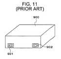
- an inlet 902 of AC power supplyis provided on the main body of the entertainment system 900 .
- the entertainment system 900is provided with a power switch 901 , it is normally provided independently of the AC inlet 902 . The appearance of such a state is shown in FIG. 11 .
- the switch 901 and inlet 902are mounted separately, and thus wiring has to be carried out separately as well. As a consequent, it requires much time and effort in assembling.
- the wiring in the entertainment systemshould be provided with an undesirable radiation restraining element such as a ferrite core.
- an undesirable radiation restraining elementsuch as a ferrite core.
- the undesirable radiation restraining elementhas to be mounted on the wiring in the entertainment system after the switch is mounted and when the power wiring is carried out. Therefore, there is a case where the mounted undesirable radiation restraining element obstructs the assembly operation.
- the flexibility in arrangement of components within the enclosureis decreased.
- the first object of the present inventionis to provide a switch inlet unit comprising a switch and an inlet that can be easily mounted to the entertainment system.
- the second object of the present inventionis to provide the switch inlet unit of a structure that can be easily assembled.
- the third object of the present inventionis to provide a switch inlet unit that eliminates the need for providing an undesirable radiation restraining element at some midpoint of wiring.
- the switch inlet unit for achieving the first object of the inventionis a switch inlet unit to be mounted on electronic equipment comprising a power switch, an inlet, and a case for receiving the power switch and the inlet, wherein a terminal of the power switch and a terminal of the inlet are electrically connected in the case, and a switching lever of the power switch and an inserting hole of the inlet are aligned on the same surface of the case.
- the switch inlet unit for achieving the second object of the inventionis a switch inlet unit according to the switch inlet unit, wherein the case comprises a case body and a cover that is detachable to the case body, and the power switch and the inlet are held within the case body.
- the switch inlet unit for achieving the third object of the inventionis a switch inlet unit according to the switch inlet unit, wherein the cover has a through hole for passing a power distribution cable through, the power distribution cable passes through the through hole, the cover is provided with a projection for mounting an undesirable radiation restraining element, and the projection is passed through the through hole.
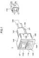
- FIG. 1is a front perspective view of the switch inlet unit according to the present invention
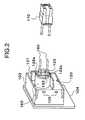
- FIG. 2is a back perspective view of the switch inlet unit according to the present invention.
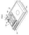
- FIG. 3is a perspective view showing a structure of the cover of the switch inlet unit according to the present invention.
- FIG. 4is a back view showing the state within the case of the switch inlet unit according to the present invention.
- FIG. 5is a back perspective view showing the state within the case of the switch inlet unit according to the present invention.
- FIG. 6is a cross section taken along the line A—A′ of the switch inlet unit according to the present invention.
- FIG. 7is a cross section taken along the line B—B′ of the switch inlet unit according to the present invention.
- FIG. 8is an explanatory drawing illustrating the state where the switch inlet unit according to the present invention is mounted in the entertainment system
- FIG. 9is an explanatory drawing illustrating the interior structure of the entertainment system when the switch inlet unit according to the present invention is mounted.
- FIG. 10is an explanatory drawing illustrating the interior structure of the entertainment system when the ferrite core is mounted on the wiring.
- FIG. 11is a drawing showing the arrangement of the power switch and AC inlet according to the conventional art.
- FIG. 1is a front perspective view of the switch inlet unit 1 (hereinafter referred to simply as “unit”).
- FIG. 2is a back perspective view of the case.
- the unit 1comprises a case 100 formed of an insulating material, a power switch 101 (hereinafter referred to simply as “switch”), and an inlet 102 . It is also possible to provide a switch inlet unit 1 by connecting extension cables 150 to the unit 1 in advance.
- the case 100comprises a case body 103 and a cover 120 for being detachably mounted on the backside of the case body 103 .
- the switch 101 and the inlet 102are received within the case 100 . More specifically, a switching lever 119 of the switch 101 and an inserting hole 112 of the inlet 102 are arranged on the front side of the case body 103 .
- the mounting plate 104 m ybe formed integrally with the case body 103 . 103 when the cover 120 is removed from the case 100 .
- a pair of terminals 111 a and 111 bare provided on the back surface of the switch 101 , each of which is to be connected with each of distribution cable 150 and a pair of terminals 112 a and 112 b, each of which is to be connected with the inlet 103 .
- a pair of terminals 113 a and 113 bare led through the through hole 123 provided on the projection 122 of the cover 120 to the outside of the unit 1 .
- the terminals 112 a and 112 b of the switch and the terminals 113 a and 113 b of the inletare respectively connected by metallic members 114 a and 114 b .
- the joints between the terminals 112 a and 112 b , 113 a and 113 b and the metallic members 114 a and 114 bare soldered.
- FIG. 6is a cross section taken along the line A—A′ of FIG. 4 .
- the terminals 112 a and 112 b , 113 a and 113 b and the conductive members 114 a and 114 bare fixed by solder 115 .
- Each of the metallic members 114 a and 114 bis formed in the shape of a plate.
- FIG. 7is a cross section taken along the line B—B′ of FIG. 4 .
- the terminals 111 a and 111 bare held within the projection 122 and protected thereby.
- FIG. 3shows the state of the cover 120 when detached from the case body 103 .
- the cover 120comprises locking portions 106 on the side surface for locking to the case body 103 , a projection 122 on the backside, and a protective wall 121 .
- the projection 122is provided with through holes 123 for leading the power distribution cables 150 out.
- the each through holes 123is provided with a terminal 111 a and 111 b held therein.
- the cover 120is formed of an insulating material, and the outer shape and dimension of the projection 122 are such that an undesirable radiation restraining element of a hollow cylindrical shape, for example a ferrite core 160 , may be mounted thereon.
- the projection 122is also provided with locking portions 122 a for locking the ferrite core 160 on the tip thereof.
- FIG. 1 and FIG. 2show the state where the cover 120 is locked on the case body 103 by the locking portion 106 .
- a socket 170 to be connected to other equipmentis connected to the tip of the cables 150 .
- the projection 122is provided with the ferrite core 160 thereon.
- the ferrite core 160may be attached on the projection 122 by adhesives or the like, or may be detachably locked by means of the locking portions 122 a provided on the projection 122 .
- the ferrite core 160 mounted on the cover 120is protected by the protective wall 121 .
- FIG. 8shows the appearance an entertainment system 300 when the unit 1 is mounted thereto.
- the unit 1is mounted on the enclosure 301 of the entertainment system 300 on the backside thereof so that the switching lever 119 of the switch 101 and the inserting hole 112 of the inlet 102 are exposed.
- FIG. 9is an internal structure of the entertainment system 300 in the same state as FIG. 8 .
- the entertainment system 300comprises at least an enclosure 301 , a unit 1 mounted on the enclosure 301 , a power unit 302 , a connector unit 303 , a disc unit 304 , and an exhaust fan 305 .
- the unit 1 and the power unit 302are interconnected by the cables 150 .
- the switch inlet unit 1 of the present inventioncomprises the switch 101 , the inlet 102 received in the case 100 , and the wiring already carried out in advance. Therefore, it is not necessary to mount the switch and the inlet independently to the entertainment system and carry out wiring after that. Therefore, the mounting operation can be easily done.
- the switching lever of the switch and the inserting hole of the inletare arranged on the same surface of the case, so that the user of the entertainment system 300 can operate it easily when the unit 1 is mounted onto the entertainment system.
- the case 100 of the unit 1comprises two parts, that is, a case body 103 and a cover 120 . Therefore, since the number of the components that constitute the unit 1 is small, it is easy to assemble.
- the terminals of the switch 111are standing substantially perpendicular to the back surface of the case and received within the projection 122 of the cover 120 .
- the distribution cables 150are connected and led through the through holes 123 of the projection 122 to the outside.
- FIG. 10shows the unit 1 according to the present embodiment illustrating the case where the ferrite core 160 is mounted on the distribution cable 150 .
- the ferrite core 160since the ferrite core 160 is not fixed to the cover 120 , the ferrite core 160 exists somewhere on the cable 150 . Therefore, assembly operation of the entertainment system 300 requires time and effort. In contrast to it, when the ferrite core 160 is fixed to the cover 120 as shown in FIG. 9, assembly operation of the entertainment system 300 can be performed easily.
- what is to be consideredis only the arrangement of the unit 1 , whereby flexibility of the design increases.
- a switch inlet unitcomprising a switch and an inlet for facilitating assembly operation of the entertainment system is provided.
- a switch inlet unithaving a structure in which the assembly can be carried out easily is provided.
- a switch inlet unit having a detachable undesirable radiation retaining elementis provided.
Landscapes
- Switch Cases, Indication, And Locking (AREA)
- Switches With Compound Operations (AREA)
- Details Of Connecting Devices For Male And Female Coupling (AREA)
Abstract
Description
Claims (6)
Applications Claiming Priority (2)
| Application Number | Priority Date | Filing Date | Title |
|---|---|---|---|
| JP11-252265 | 1999-09-06 | ||
| JP25226599AJP3593285B2 (en) | 1999-09-06 | 1999-09-06 | Switch / inlet unit and entertainment device |
Publications (1)
| Publication Number | Publication Date |
|---|---|
| US6515851B1true US6515851B1 (en) | 2003-02-04 |
Family
ID=17234842
Family Applications (1)
| Application Number | Title | Priority Date | Filing Date |
|---|---|---|---|
| US09/655,212Expired - LifetimeUS6515851B1 (en) | 1999-09-06 | 2000-09-05 | Switch inlet unit and entertainment system |
Country Status (11)
| Country | Link |
|---|---|
| US (1) | US6515851B1 (en) |
| EP (1) | EP1150396A4 (en) |
| JP (1) | JP3593285B2 (en) |
| KR (1) | KR20010089389A (en) |
| CN (1) | CN1327624A (en) |
| AU (1) | AU6872400A (en) |
| BR (1) | BR0007080A (en) |
| CA (1) | CA2350024A1 (en) |
| HK (1) | HK1042167A1 (en) |
| RU (1) | RU2001115130A (en) |
| WO (1) | WO2001018917A1 (en) |
Cited By (7)
| Publication number | Priority date | Publication date | Assignee | Title |
|---|---|---|---|---|
| US20030160513A1 (en)* | 2002-02-25 | 2003-08-28 | Bramble Matthew Forbes | Power supply arrangements |
| US6657852B2 (en)* | 2001-12-13 | 2003-12-02 | Weidmuller Interface Gmbh & Co. | Junction box and distributor assembly |
| US20050250360A1 (en)* | 2004-05-10 | 2005-11-10 | Eastman Kodak Company | Multiuse power entry module |
| US7394035B1 (en)* | 2007-06-18 | 2008-07-01 | Fsp Technology Inc. | Anti-switch on/off device |
| US20080194151A1 (en)* | 2005-03-07 | 2008-08-14 | Achim Gleissner | Plug-In Socket Provided with a Voltage Converter |
| US20090090608A1 (en)* | 2007-10-09 | 2009-04-09 | Kathleen Kyser Van Dyne | Electrical receptical |
| US20100175978A1 (en)* | 2009-01-09 | 2010-07-15 | Delta Electronics, Inc. | Electric power socket module |
Families Citing this family (4)
| Publication number | Priority date | Publication date | Assignee | Title |
|---|---|---|---|---|
| JP4241805B2 (en) | 2006-11-22 | 2009-03-18 | 船井電機株式会社 | Power switch mounting structure for thin display devices |
| DE102009022075A1 (en)* | 2009-05-20 | 2010-11-25 | Epcos Ag | Device installation device and method of manufacture |
| CN107230566B (en)* | 2017-07-28 | 2019-04-02 | 京东方科技集团股份有限公司 | Switch the assemble method of package assembly, display device and the package assembly |
| DE102019211904B4 (en)* | 2019-08-08 | 2021-02-18 | Ellenberger & Poensgen Gmbh | Plug module with a mounting plate |
Citations (18)
| Publication number | Priority date | Publication date | Assignee | Title |
|---|---|---|---|---|
| US4266266A (en)* | 1978-12-21 | 1981-05-05 | Sanner George E | Electrical fixture intended primarily for outdoor use and designed to protect an electrical device housed therein from the elements |
| DE3302192A1 (en) | 1983-01-24 | 1984-07-26 | Siemens AG, 1000 Berlin und 8000 München | Apparatus plug with an integrated electrical suppression filter |
| US4482789A (en)* | 1982-09-27 | 1984-11-13 | Mcvey Jack L | Apparatus for preventing unauthorized use of electrically powered equipment |
| US4488201A (en) | 1983-02-15 | 1984-12-11 | Corcom, Inc. | A.C. Power entry module |
| JPH048278A (en) | 1990-04-27 | 1992-01-13 | Asahi Glass Co Ltd | Tobacco leaf and method for treating the same |
| JPH0485347A (en) | 1990-07-30 | 1992-03-18 | Okura Ind Co Ltd | Cellulosic molding composition and preparation thereof |
| US5434740A (en) | 1993-07-08 | 1995-07-18 | Corcom, Inc. | Power entry module |
| US5444601A (en)* | 1992-01-10 | 1995-08-22 | Kabushiki Kaisha Toshiba | Personal computer having an expansion board connector restrained by a wall and supporting a circuit board |
| DE4437288A1 (en) | 1994-10-18 | 1995-09-14 | Siemens Nixdorf Inf Syst | Mains input module for electronic apparatus |
| EP0684057A1 (en) | 1994-05-27 | 1995-11-29 | Sony Corporation | Game apparatus with memory function |
| US5595494A (en)* | 1994-10-05 | 1997-01-21 | Damac Products Inc | Universally mounted power strip |
| US5604661A (en)* | 1994-12-28 | 1997-02-18 | Fujitsu Limited | Structure for mounting switch or the like to electric apparatus |
| US5819912A (en)* | 1995-01-31 | 1998-10-13 | Itw Switches Asia Ltd. | Slide selector switch and inlet outlet device |
| JPH1154226A (en) | 1997-08-06 | 1999-02-26 | Soogo:Kk | Extension code |
| US5949640A (en)* | 1997-08-19 | 1999-09-07 | Statpower Technologies Corp. | Power inverter with re-orientable display panel and AC port modules |
| US6201197B1 (en)* | 1999-07-26 | 2001-03-13 | Alps Electric Co., Ltd. | Switch device with AC inlet |
| US6313420B1 (en)* | 2000-04-13 | 2001-11-06 | Alps Electric Co., Ltd. | Slide switch |
| US6344619B1 (en)* | 1999-07-16 | 2002-02-05 | Matsushita Electric Industrial Co., Ltd. | Multi-directional operating switch and multi-directional operating device using the same |
Family Cites Families (2)
| Publication number | Priority date | Publication date | Assignee | Title |
|---|---|---|---|---|
| JPH048278U (en)* | 1990-05-07 | 1992-01-24 | ||
| JPH0485347U (en)* | 1990-11-29 | 1992-07-24 |
- 1999
- 1999-09-06JPJP25226599Apatent/JP3593285B2/ennot_activeExpired - Fee Related
- 2000
- 2000-09-05USUS09/655,212patent/US6515851B1/ennot_activeExpired - Lifetime
- 2000-09-06EPEP00956973Apatent/EP1150396A4/ennot_activeWithdrawn
- 2000-09-06BRBR0007080-7Apatent/BR0007080A/ennot_activeApplication Discontinuation
- 2000-09-06AUAU68724/00Apatent/AU6872400A/ennot_activeAbandoned
- 2000-09-06CNCN00802277Apatent/CN1327624A/enactivePending
- 2000-09-06HKHK02101861.2Apatent/HK1042167A1/enunknown
- 2000-09-06KRKR1020017005520Apatent/KR20010089389A/ennot_activeWithdrawn
- 2000-09-06CACA002350024Apatent/CA2350024A1/ennot_activeAbandoned
- 2000-09-06WOPCT/JP2000/006062patent/WO2001018917A1/ennot_activeApplication Discontinuation
- 2000-09-06RURU2001115130/09Apatent/RU2001115130A/ennot_activeApplication Discontinuation
Patent Citations (18)
| Publication number | Priority date | Publication date | Assignee | Title |
|---|---|---|---|---|
| US4266266A (en)* | 1978-12-21 | 1981-05-05 | Sanner George E | Electrical fixture intended primarily for outdoor use and designed to protect an electrical device housed therein from the elements |
| US4482789A (en)* | 1982-09-27 | 1984-11-13 | Mcvey Jack L | Apparatus for preventing unauthorized use of electrically powered equipment |
| DE3302192A1 (en) | 1983-01-24 | 1984-07-26 | Siemens AG, 1000 Berlin und 8000 München | Apparatus plug with an integrated electrical suppression filter |
| US4488201A (en) | 1983-02-15 | 1984-12-11 | Corcom, Inc. | A.C. Power entry module |
| JPH048278A (en) | 1990-04-27 | 1992-01-13 | Asahi Glass Co Ltd | Tobacco leaf and method for treating the same |
| JPH0485347A (en) | 1990-07-30 | 1992-03-18 | Okura Ind Co Ltd | Cellulosic molding composition and preparation thereof |
| US5444601A (en)* | 1992-01-10 | 1995-08-22 | Kabushiki Kaisha Toshiba | Personal computer having an expansion board connector restrained by a wall and supporting a circuit board |
| US5434740A (en) | 1993-07-08 | 1995-07-18 | Corcom, Inc. | Power entry module |
| EP0684057A1 (en) | 1994-05-27 | 1995-11-29 | Sony Corporation | Game apparatus with memory function |
| US5595494A (en)* | 1994-10-05 | 1997-01-21 | Damac Products Inc | Universally mounted power strip |
| DE4437288A1 (en) | 1994-10-18 | 1995-09-14 | Siemens Nixdorf Inf Syst | Mains input module for electronic apparatus |
| US5604661A (en)* | 1994-12-28 | 1997-02-18 | Fujitsu Limited | Structure for mounting switch or the like to electric apparatus |
| US5819912A (en)* | 1995-01-31 | 1998-10-13 | Itw Switches Asia Ltd. | Slide selector switch and inlet outlet device |
| JPH1154226A (en) | 1997-08-06 | 1999-02-26 | Soogo:Kk | Extension code |
| US5949640A (en)* | 1997-08-19 | 1999-09-07 | Statpower Technologies Corp. | Power inverter with re-orientable display panel and AC port modules |
| US6344619B1 (en)* | 1999-07-16 | 2002-02-05 | Matsushita Electric Industrial Co., Ltd. | Multi-directional operating switch and multi-directional operating device using the same |
| US6201197B1 (en)* | 1999-07-26 | 2001-03-13 | Alps Electric Co., Ltd. | Switch device with AC inlet |
| US6313420B1 (en)* | 2000-04-13 | 2001-11-06 | Alps Electric Co., Ltd. | Slide switch |
Cited By (11)
| Publication number | Priority date | Publication date | Assignee | Title |
|---|---|---|---|---|
| US6657852B2 (en)* | 2001-12-13 | 2003-12-02 | Weidmuller Interface Gmbh & Co. | Junction box and distributor assembly |
| US20030160513A1 (en)* | 2002-02-25 | 2003-08-28 | Bramble Matthew Forbes | Power supply arrangements |
| US7663265B2 (en)* | 2002-02-25 | 2010-02-16 | Audio Partnership Plc | Power supply arrangements |
| US20050250360A1 (en)* | 2004-05-10 | 2005-11-10 | Eastman Kodak Company | Multiuse power entry module |
| US20080194151A1 (en)* | 2005-03-07 | 2008-08-14 | Achim Gleissner | Plug-In Socket Provided with a Voltage Converter |
| US8777639B2 (en)* | 2005-03-07 | 2014-07-15 | Sennheiser Electronic Gmbh & Co. Kg | Plug-in socket provided with a voltage converter |
| US7394035B1 (en)* | 2007-06-18 | 2008-07-01 | Fsp Technology Inc. | Anti-switch on/off device |
| US20090090608A1 (en)* | 2007-10-09 | 2009-04-09 | Kathleen Kyser Van Dyne | Electrical receptical |
| US7527519B2 (en)* | 2007-10-09 | 2009-05-05 | Kathleen Kyser Van Dyne | Electrical receptical |
| US20100175978A1 (en)* | 2009-01-09 | 2010-07-15 | Delta Electronics, Inc. | Electric power socket module |
| US7772511B2 (en)* | 2009-01-09 | 2010-08-10 | Delta Electronics, Inc. | Electric power socket module |
Also Published As
| Publication number | Publication date |
|---|---|
| WO2001018917A1 (en) | 2001-03-15 |
| CN1327624A (en) | 2001-12-19 |
| BR0007080A (en) | 2001-07-31 |
| HK1042167A1 (en) | 2002-08-02 |
| CA2350024A1 (en) | 2001-03-15 |
| KR20010089389A (en) | 2001-10-06 |
| EP1150396A1 (en) | 2001-10-31 |
| JP2001076566A (en) | 2001-03-23 |
| EP1150396A4 (en) | 2002-12-04 |
| RU2001115130A (en) | 2003-06-27 |
| JP3593285B2 (en) | 2004-11-24 |
| AU6872400A (en) | 2001-04-10 |
Similar Documents
| Publication | Publication Date | Title |
|---|---|---|
| US6515851B1 (en) | Switch inlet unit and entertainment system | |
| US7292130B2 (en) | Fusible link and battery fuse unit containing the fusible link | |
| US6592400B2 (en) | Easily assembled fan structure feasible for hot swap | |
| US6297982B1 (en) | Rectifying device outputting multiple power signals | |
| JP2000156924A (en) | Electrical connection box | |
| US10840617B2 (en) | Electronic device | |
| JPH0751746Y2 (en) | Circuit board connection device | |
| JP2001101908A (en) | Lighting device | |
| JP4076183B2 (en) | Switch device-Printed wiring board-Combination | |
| JP5128179B2 (en) | Electrical junction box | |
| KR100766996B1 (en) | Automotive Fuses and Relay Boxes | |
| US6249438B1 (en) | Electrical device having a plug outlet | |
| JPH0611282U (en) | Connector mounting structure for CATV equipment | |
| JP3538986B2 (en) | Wiring board assembly structure | |
| JP3451798B2 (en) | AC inlet | |
| JPH0688076U (en) | Input/Output Connectors | |
| JP2596552Y2 (en) | CATV equipment housing | |
| JPS59149B2 (en) | Electronic device housing assembly | |
| KR100433983B1 (en) | The feeding structure of mobile phone antenna | |
| JP2023026023A (en) | Distribution board and breaker | |
| JPH10310003A (en) | In-vehicle unit | |
| KR200165038Y1 (en) | Outer case structure of power supply in electromechatronics | |
| JPH08116192A (en) | Coaxial cable shield structure | |
| JPH10335915A (en) | Antenna device | |
| JPH08306437A (en) | Connecting device |
Legal Events
| Date | Code | Title | Description |
|---|---|---|---|
| AS | Assignment | Owner name:SONY COMPUTER ENTERTAINMENT INC., JAPAN Free format text:ASSIGNMENT OF ASSIGNORS INTEREST;ASSIGNORS:OOTORI, YASUHIRO;MURASAWA, OSAMU;REEL/FRAME:011374/0133;SIGNING DATES FROM 20001128 TO 20001130 | |
| FEPP | Fee payment procedure | Free format text:PAYOR NUMBER ASSIGNED (ORIGINAL EVENT CODE: ASPN); ENTITY STATUS OF PATENT OWNER: LARGE ENTITY | |
| STCF | Information on status: patent grant | Free format text:PATENTED CASE | |
| FPAY | Fee payment | Year of fee payment:4 | |
| FEPP | Fee payment procedure | Free format text:PAYER NUMBER DE-ASSIGNED (ORIGINAL EVENT CODE: RMPN); ENTITY STATUS OF PATENT OWNER: LARGE ENTITY Free format text:PAYOR NUMBER ASSIGNED (ORIGINAL EVENT CODE: ASPN); ENTITY STATUS OF PATENT OWNER: LARGE ENTITY | |
| FPAY | Fee payment | Year of fee payment:8 | |
| AS | Assignment | Owner name:SONY NETWORK ENTERTAINMENT PLATFORM INC., JAPAN Free format text:CHANGE OF NAME;ASSIGNOR:SONY COMPUTER ENTERTAINMENT INC.;REEL/FRAME:027437/0369 Effective date:20100401 | |
| AS | Assignment | Owner name:SONY COMPUTER ENTERTAINMENT INC., JAPAN Free format text:ASSIGNMENT OF ASSIGNORS INTEREST;ASSIGNOR:SONY NETWORK ENTERTAINMENT PLATFORM INC.;REEL/FRAME:027449/0108 Effective date:20100401 | |
| FPAY | Fee payment | Year of fee payment:12 | |
| AS | Assignment | Owner name:DROPBOX INC, CALIFORNIA Free format text:ASSIGNMENT OF ASSIGNORS INTEREST;ASSIGNOR:SONY ENTERTAINNMENT INC;REEL/FRAME:035532/0507 Effective date:20140401 | |
| AS | Assignment | Owner name:JPMORGAN CHASE BANK, N.A., AS COLLATERAL AGENT, NE Free format text:SECURITY INTEREST;ASSIGNOR:DROPBOX, INC.;REEL/FRAME:042254/0001 Effective date:20170403 Owner name:JPMORGAN CHASE BANK, N.A., AS COLLATERAL AGENT, NEW YORK Free format text:SECURITY INTEREST;ASSIGNOR:DROPBOX, INC.;REEL/FRAME:042254/0001 Effective date:20170403 | |
| AS | Assignment | Owner name:JPMORGAN CHASE BANK, N.A., AS COLLATERAL AGENT, NEW YORK Free format text:PATENT SECURITY AGREEMENT;ASSIGNOR:DROPBOX, INC.;REEL/FRAME:055670/0219 Effective date:20210305 | |
| AS | Assignment | Owner name:DROPBOX, INC., CALIFORNIA Free format text:RELEASE BY SECURED PARTY;ASSIGNOR:JPMORGAN CHASE BANK, N.A., AS COLLATERAL AGENT;REEL/FRAME:069613/0744 Effective date:20241211 | |
| AS | Assignment | Owner name:DROPBOX, INC., CALIFORNIA Free format text:RELEASE BY SECURED PARTY;ASSIGNOR:JPMORGAN CHASE BANK, N.A., AS COLLATERAL AGENT;REEL/FRAME:069635/0332 Effective date:20241211 |