US6515635B2 - Adaptive antenna for use in wireless communication systems - Google Patents
Adaptive antenna for use in wireless communication systemsDownload PDFInfo
- Publication number
- US6515635B2 US6515635B2US09/846,693US84669301AUS6515635B2US 6515635 B2US6515635 B2US 6515635B2US 84669301 AUS84669301 AUS 84669301AUS 6515635 B2US6515635 B2US 6515635B2
- Authority
- US
- United States
- Prior art keywords
- antenna
- antenna elements
- directive
- elements
- switch
- Prior art date
- Legal status (The legal status is an assumption and is not a legal conclusion. Google has not performed a legal analysis and makes no representation as to the accuracy of the status listed.)
- Expired - Lifetime
Links
Images


Classifications
- H—ELECTRICITY
- H01—ELECTRIC ELEMENTS
- H01Q—ANTENNAS, i.e. RADIO AERIALS
- H01Q3/00—Arrangements for changing or varying the orientation or the shape of the directional pattern of the waves radiated from an antenna or antenna system
- H01Q3/24—Arrangements for changing or varying the orientation or the shape of the directional pattern of the waves radiated from an antenna or antenna system varying the orientation by switching energy from one active radiating element to another, e.g. for beam switching
- H01Q3/242—Circumferential scanning
- H—ELECTRICITY
- H01—ELECTRIC ELEMENTS
- H01Q—ANTENNAS, i.e. RADIO AERIALS
- H01Q19/00—Combinations of primary active antenna elements and units with secondary devices, e.g. with quasi-optical devices, for giving the antenna a desired directional characteristic
- H01Q19/28—Combinations of primary active antenna elements and units with secondary devices, e.g. with quasi-optical devices, for giving the antenna a desired directional characteristic using a secondary device in the form of two or more substantially straight conductive elements
- H01Q19/32—Combinations of primary active antenna elements and units with secondary devices, e.g. with quasi-optical devices, for giving the antenna a desired directional characteristic using a secondary device in the form of two or more substantially straight conductive elements the primary active element being end-fed and elongated
- H—ELECTRICITY
- H01—ELECTRIC ELEMENTS
- H01Q—ANTENNAS, i.e. RADIO AERIALS
- H01Q21/00—Antenna arrays or systems
- H01Q21/06—Arrays of individually energised antenna units similarly polarised and spaced apart
- H01Q21/20—Arrays of individually energised antenna units similarly polarised and spaced apart the units being spaced along or adjacent to a curvilinear path
- H01Q21/205—Arrays of individually energised antenna units similarly polarised and spaced apart the units being spaced along or adjacent to a curvilinear path providing an omnidirectional coverage
Definitions
- This inventionrelates to cellular communication systems, and, more particularly, to an apparatus for use by mobile subscriber units to provide directional transmitting and receiving capabilities.
- the bulk of existing cellular antenna technologybelongs to a low- to medium-gain omni-directional class.
- An example of a unidirectional antennais the Yagi antenna shown in FIG. 1 .
- the Yagi antenna 100includes reflective antenna elements 105 , active antenna element 110 , and transmissive antenna elements 115 .
- both the reflective and transmissive antenna elements 105 , 115are electromagnetically coupled to the active antenna element 110 .
- Both the reflective antenna elements 105 and the transmissive antenna elements 115re-radiate the electromagnetic energy radiating from the active antenna element 110 .
- the reflective antenna elements 105are longer than the active antenna element 110 and spaced appropriately from the active antenna element 110 , the reflective antenna elements 105 serve as an electromagnetic reflector, causing the radiation from the active antenna element 110 to be directed in the antenna beam direction 120 , as indicated. Because the transmissive antenna elements 115 are shorter than the active antenna element 110 and spaced appropriately from the active antenna element 110 , electromagnetic radiation is allowed to propagate (i.e., transmit) past them. Due to its size, the Yagi antenna 100 is typically found on large structures and is unsuitable for mobile systems.
- phased arrays with RF combining networkshave fast scanning directive beams.
- the feed network loss and mutual coupling loss in a conventional phased arraytend to cancel out any benefits hoped to be achieved unless very costly alternatives, such as digital beam forming techniques, are used.
- an adjustable array antennahaving a central, fixed, active, antenna element and multiple, passive, antenna elements, which are reflective (i.e., re-radiates RF energy)—is taught.
- Active control of the passive elementsis provided through the use of switches and various, selectable, impedance elements. A portion of the re-radiated energy from the passive elements is picked up by the active antenna, and the phase with which the re-radiated energy is received by the active antenna is controllable.
- the present inventionprovides an inexpensive, electronically scanned, antenna array apparatus with low loss, low cost, medium directivity, and low back-lobe, as required by high transmission speed cellular systems operating in a dense multi-path environment.
- the enabling technology for the inventionis an electronic reflector array that works well in a densely packed array environment.
- the inventionis suitable for any communication system that requires indoor and outdoor communication capabilities.
- the antenna array apparatusis used with a subscriber unit.
- the antenna apparatuscan be any form of phased array antenna.
- the directive antennaincludes multiple antenna elements in an antenna assemblage.
- a feed network connected to the antenna elementsincludes at least one switch to select a state of one of the antenna elements to be in an active state in response to a control signal.
- the other antenna elementsare in a passive state, electrically coupled to an impedance to be in a reflective state.
- the antenna elements in the passive stateare electromagnetically coupled to the selected active antenna element, allowing the antenna assemblage to directionally transmit and receive signals.
- U.S. Pat. No. 5,905,473which has at least one central, fixed, active, antenna element, the present invention selects one passive antenna element to be in an active state, receiving re-radiated energy from the antenna elements remaining in the passive state.
- the directive antennamay further include an assisting switch associated with each antenna element to assist coupling the antenna elements, while in the passive state, to the respective impedances.
- the impedancesare composed of impedance components.
- the impedance componentsinclude a delay line, lumped impedance, or combination thereof.
- the lumped impedanceincludes inductive or capacitive elements.
- the switchis preferably a solid state switch or a micro-electro machined switch (MEMS).
- MEMSmicro-electro machined switch
- the antenna assemblagemay be circular for a 360° discrete scan in N directions, where N is the number of antenna elements. At least one antenna element may be a sub-assemblage of antenna elements.
- the antenna elementsmay also be telescoping antenna elements and/or have adjustable radial widths.
- the passive antenna elementsmay also be adjustable in distance from the active antenna elements.
- the impedance to which the antenna elements are coupled in the passive stateare typically selectable from among plural impedances.
- a selectable impedanceis composed of impedance components, switchably coupled to the associated antenna element, where the impedance component includes a delay line, lumped impedance, or combination thereof.
- the lumped impedancemay be a varactor for analog selection, or capacitor or inductor for predetermined values of impedance.
- the directive antennais suitable for use in a high data rate network having greater than 50 kbits per second data transfer rates.
- the high data rate networkmay use CDMA2000, 1eV-DO, 1Extreme, or other such protocol.
- FIG. 1is a prior art directional antenna
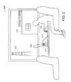
- FIG. 2is an illustration of an environment in which the present invention directive antenna may be employed
- FIG. 3is a mechanical diagram of the directive antenna of FIG. 2 operated by a feed network
- FIG. 4is a schematic diagram of an embodiment of the feed network having a switch used to control the directive antenna of FIG. 3;
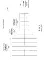
- FIG. 5is a schematic diagram of a solid state switch having losses exceeding an acceptable level for use in the circuit of FIG. 4;
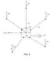
- FIG. 6is a schematic diagram of an alternative embodiment of the feed network used to control the directive antenna of FIG. 3;
- FIG. 7is a schematic diagram of an alternative embodiment of the feed network of FIG. 6;
- FIG. 8is a schematic diagram of yet another alternative embodiment of the feed network of FIG. 6;
- FIG. 9is a schematic diagram of an alternative embodiment of the feed network of FIG. 4;
- FIG. 10is a schematic diagram of an alternative embodiment of the directive antenna of FIG. 3 having an omni-directional mode
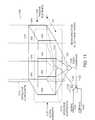
- FIG. 11is a schematic diagram of yet another alternative embodiment of the directive antenna of FIG. 3.
- FIG. 12is a flow diagram of an embodiment of a process used to operate the directive antenna of FIG. 3 .
- FIG. 2is an environment in which a directive antenna, also referred to as an adaptive antenna, is useful for a subscriber unit (i.e., mobile station).
- the environment 200shows a passenger 205 on a train using a personal computer 210 to perform wireless data communication tasks.
- the personal computer 210is connected to a directive antenna 215 .
- the directive antenna 215produces a directive beam 220 for communicating with an antenna tower 225 having an associated base station (not shown).
- the angle between the directive antenna 215 and the antenna tower 225changes. As the angle changes, it is desirable that the directive antenna 215 change the angle of the directive beam 220 to stay on target with the antenna tower 225 . By staying directed toward the antenna tower 225 , the directive beam 220 maximizes its gain in the direction of the antenna tower 225 . By having a high gain between the antenna tower 225 and the directive antenna 215 , the data communications have a high signal-to-noise ratio (SNR).
- SNRsignal-to-noise ratio
- the subscriber unitmay optimize the forward link beam pattern based on a received pilot signal.
- the reverse link beam patternmay be based on a signal quality of a given received signal via a feedback metric over the forward link.
- the subscriber unitmay steer a reverse beam in the direction of a maximum received power of a forward beam from a given base station, while optimizing a forward beam on a best signal-to-noise (SNR) or carrier-to-interference (C/I) level.
- SNRsignal-to-noise
- C/Icarrier-to-interference
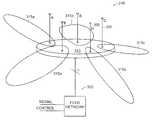
- FIG. 3is a close-up view of an embodiment of the directive antenna 215 .
- the directive antenna 215is an antenna assemblage having five antenna elements 305 .
- the antenna elements 305are labeled A-E.
- the antenna elements 305are mechanically coupled to a base 310 , which includes a ground plane on the upper surface of the base.
- the directive antenna 215can scan discretely in 360 , at 72 intervals, as indicated by beams 315 a , 315 b , . . . , 315 e corresponding to antenna elements 305 (A-E).
- one antenna element 305is active at any one time as provided by feed network 300 .
- antenna Ais active, then a respective antenna beam 315 a is produced, since antenna elements B-E are in a reflective mode while antenna A is active.
- the other antenna elements 305produce beams, when active, in a direction away from the reflective antenna elements. It should be understood that the directive antenna is merely exemplary in antenna element count and configuration and that more or fewer antenna elements 305 and configuration changes may be employed without departing from the principles of the present invention.
- the low loss of the directive antenna 215is realized by using practically lossless reflective elements, and only one active element, which is selectable by a switch, as later described. Low cost is achieved by changing from the conventional RF combining network concept, which employs power dividers and costly phase shifters, to a passive reflector array. Medium directivity and low back lobe are made possible by keeping the element spacing to a small fraction of a wavelength. The close spacing normally means high loss, due to excess mutual coupling. But, in a reflective mode, the coupled power is re-radiated rather than lost.
- Electronic scanningis implemented through a relatively low loss, single-pole, multi-throw switch, in one embodiment. Continuous scanning, if opted, is achieved through perturbing the phases of antenna elements in the reflective mode.
- the directive antenna 215typically has 7 to 8 dBi of gain, which is an improvement over the 4 to 5 dBi found in comparable conventionally fed phased arrays.
- Various embodiments of the directive antenna 215 and feed network 300are described below.
- FIG. 4is a schematic diagram of the directive antenna 215 having an embodiment of a feed network comprising a single switch to control which antenna element 315 is active.
- the switch 400is a single-pole, multiple-throw switch having the pole 402 connected to a transmitter/receiver (Tx/Rx) (not shown).
- the switch 400has a switching element 410 that electrically connects the pole 402 to one of five terminals 405 .
- the terminals 405are electrically connected to respective antenna elements 305 via transmission lines 415 .
- the transmission linesare 50-ohm and have the same length, L, spanning from the switch 400 to the antenna elements 305 .
- the switch 400is shown as being a mechanical type of switch. Although possible to use a mechanical switch, a mechanical switch tends to be larger in physical dimensions than desirable, plus not typically robust for many operations and slow. Therefore, switches of other types of technologies are preferably employed. No matter the type of switch technology chosen, the performance should be high impedance in the ‘open’ state, and provide excellent transmittance (i.e., low impedance) in the ‘closed’ state.
- MEMSmicro-electro machine switch
- gallium arsenideprovides a solid-state switch technology that, when high-enough quality, can provide the necessary performance.
- the concern with solid-state technologyis consistency and low-loss reflectivity from port-to-port and chip-to-chip. Good quality characteristics allow for high quantity production rates yielding consistent antenna characteristics having improved directive gain.
- Another solid state technology embodimentincludes the use of a pin diode having a 0.1 dB loss, as discussed below in reference to FIG. 6 .
- a controller(not shown) provides control signals to control lines 420 that control the state of the switch 400 .
- the controllermay be any processing unit, digital or analog, capable of performing typical processing and control functions.
- a binary coded decimal (BCD) representation of the control signaldetermines which antenna element 305 is active in the antenna array.
- the active antennaagain, determines the direction in which the directive beam is directed.
- the switch 400couples the Tx/Rx to antenna A. If the switch 400 were coupled to more than eight antenna elements, then more than three control lines 420 would be necessary (e.g., four control lines can select sixteen different switch states).
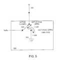
- FIG. 5is an example of a solid state switch 500 that has been found less optimal than a switch providing a hard open.
- the solid state switch 500has a single-pole, double-throw configuration.
- the switch 500In the closed-state as shown, the switch 500 has a pole 505 providing signals from the Tx/Rx to the antenna 305 . However, in the closed-state, there is electrical coupling from the pole 505 to a ground terminal 510 .
- the electrical couplingis due to the fact the solid-state technology (e.g., CMOS) does not provide complete isolation from the pole 505 to the ground terminal 510 in the state shown. As a result, there is a ⁇ 1.5 dB loss in the direction from the pole 505 to the ground terminal 510 , and a reflected loss of ⁇ 1.5 dB from the ground terminal 510 back to the pole 505 . The cumulative loss is ⁇ 3 dB. In other words, the advantage gained by using the directive antenna 215 is lost due to the electrical characteristics of this solid state switch 500 . In the other switch embodiments described herein, the losses described with respect to this solid state switch 500 are not found, and, therefore, offer viable switching solutions.
- the solid-state technologye.g., CMOS
- FIG. 6is a schematic diagram of an alternative five element antenna array 215 .
- the antenna array 215is fed by a single-path network 605 .
- the network 605includes five 50-ohm transmission lines 610 , each being connected to a respective antenna element 305 .
- the other end of each transmission line 610is connected respectively to a switching diode 615 .
- Each diode 615is connected, in turn, to one of five additional 50 ohm transmission lines 620 .
- the transmission lines 620are also connected to a 50-ohm transmission line 625 at a junction 630 .
- the transmission line 625is connected to the junction 630 and an output 635 .
- diodes 615In use, four of the five diodes 615 are normally open.
- the open diodesserve as open-circuit terminations for the four associated antenna elements so that these antenna elements are in a reflective mode.
- the remaining diodeis conducting, thus connecting the fifth antenna to the output 635 and making the respective antenna active.
- All the transmission lines 610have the same impedance because there is no power combining; there is only power switching. Selection of the state of the diodes is made through the use of respective DC control lines (not shown).
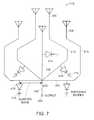
- FIG. 7Another embodiment, shown in FIG. 7, has the antenna array 215 having five antenna elements 305 , each being connected to one of five transmission lines 610 .
- Each of the transmission lines 610is connected, in turn, to a switching diode 615 and a quarter-wave line 705 connecting at a junction 630 .
- the quarter-wave lines 705are connected to an output 635 through an output line 625 .
- each diode 615appears as an open circuit when viewed from the junction 630 . This is the dual of the circuit discussed above in reference to FIG. 6, so that the impedance shown to the reflective antenna elements 305 is a short circuit. It is further observed that the lengths of the transmission lines 610 connecting the diodes 615 to the antenna elements 305 can be sized to adjust the amount of phase delay between the diodes 615 and antenna elements 305 .
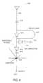
- FIG. 8is yet another embodiment of a feed network for controlling the antenna array 215 . Shown is a single branch 800 of the feed network, where the single branch 800 provides continuous scanning rather than mere step scanning, as in the case of the branches of the previous network 605 . The continuous scanning is achieved by providing individual phase control to the reflective elements.
- each branch 800There are three diodes on each branch 800 .
- One diodeis a first switching diode 615 , located closest to the junction 630 , which is used for the selection of the antenna element 305 that is to be active.
- the second diodeis a varactor 805 , which provides the continuously variable phase to the antenna element 305 when in a reflective mode.
- the third diodeis another switching diode 615 , which adds one digital phase bit to the antenna element 305 when in the reflective mode, where the phase bit is typically 180°.
- the phaseis added by the delay loop 810 , which is coupled to both anode and cathode of the second switching diode 615 .
- the phase bitis used to supplement the range of the varactor 805 .
- the capacitors 815are used to pass the RF signal and inhibit passage of the DC control signals used to enable and disable the diodes 615 .
- FIG. 9is yet another embodiment in which one of the antenna elements 305 is in active mode, and four of the five antenna elements 305 are in reflective modes.
- a central switch 400directs a signal to one of the five antenna elements 305 in response to a control signal on the control lines 420 . As shown, the switch 400 is directing the signal to antenna A via the respective transmission line 415 .
- the transmission line 415is connected at the distal end from the switch 400 to an assisting switch 905 , which is a single-pole, double-throw switch.
- the assisting switch 905connects the antenna element 305 to either the transmission line 415 to receive the signal or to an inductive element 910 .
- the antenna element 305When coupled to the inductive element 910 , the antenna element 305 has an effective length increase, causing the antenna element 305 to be in the reflective mode. This effective length increase makes the antenna element 305 appear as a reflective antenna element 105 (FIG. 1 ), as described in reference to the Yagi antenna.
- the extra switches 905 and inductive elements 910assist the feed network in coupling the antenna elements 305 to an inductive element, rather than using the transmission line 415 in combination with the open circuit of the central switch 400 to provide the inductance.
- the assisting switch 905is used, in particular, when the central switch 400 is lossy or varies in performance from port-to-port when open circuited.
- a typical assisting switch 905has a ⁇ 0.5 dB loss, which is more efficient than the ⁇ 3 dB loss of the central switch 500 (FIG. 5 ).
- the inductive elementcan be any form of impedance, predetermined or dynamically varied. Impedances can be a delay line or lumped impedance where the lumped impedance, includes inductive and/or capacitive elements. It should also be understood that the assisting switches 905 , as in the case of the central switch 400 , can be solid state switches, micro-electro machined switches (MEMS), pin diodes, or other forms of switches that provide the open and closed circuit characteristics required for active and passive performance characteristics by the antenna elements 305 .
- MEMSmicro-electro machined switches
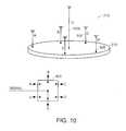
- FIG. 10is an alternative embodiment of the antenna assembly 215 of FIG. 3 .
- the same five antenna elements 305are included on the base 310 .
- This embodimentalso includes a longer antenna element (antenna O) 1000 , which is used for omni-directional mode.
- the switch 400includes a sixth terminal to which antenna O is connected.
- antenna Ois connected to antenna O.
- the other antenna elements 305are in reflective mode.
- the extended length of the omni-directional antenna, antenna Ofacilitates transmitting and receiving signals over the other antenna elements 305 .
- Antenna Omay be telescoping, so as to allow a user to keep antenna O short unless omni-directional mode is desired.
- FIG. 11is an alternative embodiment of the antenna assembly 215 (FIG. 3) that may be operated by teachings of the present invention.
- an antenna assembly 1100is formed in the shape of a rectangular assembly 1102 .
- the antenna elements 305are located vertically on the sides of the assembly 1102 .
- Transmission lines 1120each have the same length and 50-ohm impedance and electrically connect the antenna elements 305 to fixed combiners 1125 .
- the fixed combiners 1125are electrically connected to a single-pole, single-throw switch 1135 .
- the switch 1135is controlled by a control signal 1145 and transmits RF signals 1140 to, or receives RF signals 1140 from, the antenna elements 305 .
- the embodiment of FIG. 11has the antenna elements 305 arranged in two arrays: one array on the front of the assembly 1102 and a second array on the rear of the assembly 1102 .
- the switch 1135determines which array of antenna elements 305 is in reflective mode and which array is in active mode.
- the antenna elements on the front of the assembly 1102are active elements 1110
- the antenna elements 305 on the rear of the assembly 1102are passive elements 1105 .
- the arraysare separated by, for example, one-quarter wavelengths, thus electromagnetically coupling the active elements 1110 and passive elements 1105 together to cause the passive elements 1105 to re-radiate electromagnetic energy.
- the passive antenna elements 1105have effective elongation 1115 above and below the assembly 1102 recall the Yagi antenna 100 (FIG. 1 ).
- the switch 1135has the same performance characteristics as the central switch 40 , as described above. Further, similar feed network arrangements as those described above could be employed in the embodiment of FIG. 12 without departing from the principles of the present invention. Also, it should be noted that (i) the transmission lines 1120 spanning between the antenna elements 305 and the fixed combiners 1125 are the same lengths and (ii) the transmission lines 1130 spanning from the switch 1135 to the fixed combiners 1125 are the same lengths. In this way, the antenna patterns fore and aft of the assembly 1100 are the same, both when the antenna elements on the front of the assembly 1100 are active and when the antenna elements 305 at the back of the assembly 1100 are active.
- FIG. 12is a flow diagram of an embodiment of a process 1200 used when operating the directive antenna 215 .
- the process 1200begins in step 1205 .
- the process 1200determines if a control signal has been received. If a control signal has been received, then, in step 1215 , the process 1200 , in response to the control signal, selects the state of one of the antenna elements 305 , or antenna assemblages in an embodiment such as shown in FIG. 11, to be in an active state while the other antenna elements 305 are in a passive state. In the passive state, the antenna elements 305 are electrically coupled to a predetermined impedance and electromagnetically coupled to the active antenna element, thereby enabling the active antenna. If, in step 1210 , the process 1200 determines that a control signal has not been received, the process 1200 loops back to step 1210 and waits for a control signal to be received.
- the process 1200 and the various mechanical and electrical embodiments described aboveare suitable for use with high data rate networks having greater than 50 kbits per second data transfer rates.
- the high data rate networkmay use an CDMA2000, 1eV-DO, 1Extreme, or other such protocol.
Landscapes
- Variable-Direction Aerials And Aerial Arrays (AREA)
Abstract
Description
Claims (28)
Priority Applications (1)
| Application Number | Priority Date | Filing Date | Title |
|---|---|---|---|
| US09/846,693US6515635B2 (en) | 2000-09-22 | 2001-05-01 | Adaptive antenna for use in wireless communication systems |
Applications Claiming Priority (2)
| Application Number | Priority Date | Filing Date | Title |
|---|---|---|---|
| US23461000P | 2000-09-22 | 2000-09-22 | |
| US09/846,693US6515635B2 (en) | 2000-09-22 | 2001-05-01 | Adaptive antenna for use in wireless communication systems |
Publications (2)
| Publication Number | Publication Date |
|---|---|
| US20020036595A1 US20020036595A1 (en) | 2002-03-28 |
| US6515635B2true US6515635B2 (en) | 2003-02-04 |
Family
ID=26928117
Family Applications (1)
| Application Number | Title | Priority Date | Filing Date |
|---|---|---|---|
| US09/846,693Expired - LifetimeUS6515635B2 (en) | 2000-09-22 | 2001-05-01 | Adaptive antenna for use in wireless communication systems |
Country Status (1)
| Country | Link |
|---|---|
| US (1) | US6515635B2 (en) |
Cited By (231)
| Publication number | Priority date | Publication date | Assignee | Title |
|---|---|---|---|---|
| US20030030594A1 (en)* | 2001-07-30 | 2003-02-13 | Thomas Larry | Small controlled parasitic antenna system and method for controlling same to optimally improve signal quality |
| US20030184492A1 (en)* | 2001-11-09 | 2003-10-02 | Tantivy Communications, Inc. | Dual band phased array employing spatial second harmonics |
| WO2003077358A3 (en)* | 2002-03-08 | 2003-12-18 | Tantivy Comm Inc | Adaptive receive and omnidirectional transmit antenna array |
| US20040032370A1 (en)* | 2001-07-25 | 2004-02-19 | Hideo Ito | Portable radio-use antenna |
| US20040033817A1 (en)* | 2002-03-01 | 2004-02-19 | Tantivy Communications, Inc. | Intelligent interface for controlling an adaptive antenna array |
| US20040046694A1 (en)* | 2002-03-14 | 2004-03-11 | Tantivy Communications, Inc. | Mobile communication handset with adaptive antenna array |
| WO2003107577A3 (en)* | 2002-06-17 | 2004-04-29 | Tantivy Comm Inc | Antenna steering scheduler for mobile station in wireless local area network |
| US20040125036A1 (en)* | 2002-09-17 | 2004-07-01 | Tantivy Communications, Inc. | Low cost multiple pattern antenna for use with multiple receiver systems |
| US20040135649A1 (en)* | 2002-05-15 | 2004-07-15 | Sievenpiper Daniel F | Single-pole multi-throw switch having low parasitic reactance, and an antenna incorporating the same |
| US20040227668A1 (en)* | 2003-05-12 | 2004-11-18 | Hrl Laboratories, Llc | Steerable leaky wave antenna capable of both forward and backward radiation |
| US20040227667A1 (en)* | 2003-05-12 | 2004-11-18 | Hrl Laboratories, Llc | Meta-element antenna and array |
| US20040227678A1 (en)* | 2003-05-12 | 2004-11-18 | Hrl Laboratories, Llc | Compact tunable antenna |
| US20040227583A1 (en)* | 2003-05-12 | 2004-11-18 | Hrl Laboratories, Llc | RF MEMS switch with integrated impedance matching structure |
| US20040259597A1 (en)* | 1998-09-21 | 2004-12-23 | Gothard Griffin K. | Adaptive antenna for use in wireless communication systems |
| US20040257292A1 (en)* | 2003-06-20 | 2004-12-23 | Wang Electro-Opto Corporation | Broadband/multi-band circular array antenna |
| US20040263408A1 (en)* | 2003-05-12 | 2004-12-30 | Hrl Laboratories, Llc | Adaptive beam forming antenna system using a tunable impedance surface |
| US20050063340A1 (en)* | 2003-06-19 | 2005-03-24 | Ipr Licensing, Inc. | Antenna steering for an access point based upon spatial diversity |
| US20050063343A1 (en)* | 2003-06-19 | 2005-03-24 | Ipr Licensing, Inc. | Antenna steering for an access point based upon control frames |
| US20050075142A1 (en)* | 2003-06-19 | 2005-04-07 | Ipr Licensing, Inc. | Antenna steering and hidden node recognition for an access point |
| US20050075141A1 (en)* | 2003-06-19 | 2005-04-07 | Ipr Licensing, Inc. | Antenna steering for an access point based upon probe signals |
| US20050088358A1 (en)* | 2002-07-29 | 2005-04-28 | Toyon Research Corporation | Reconfigurable parasitic control for antenna arrays and subarrays |
| US20050093646A1 (en)* | 2003-10-29 | 2005-05-05 | Mitsubishi Denki Kabushiki Kaisha | High frequency switch |
| US20050176469A1 (en)* | 2004-02-05 | 2005-08-11 | Interdigital Technology Corporation | Method for identifying pre-candidate cells for a mobile unit operating with a switched beam antenna in a wireless communication system, and corresponding system |
| US20050176385A1 (en)* | 2004-02-05 | 2005-08-11 | Interdigital Technology Corporation | Method for performing measurements for handoff of a mobile unit operating with a switched beam antenna in a wireless communication system, and corresponding system |
| US20050176468A1 (en)* | 2004-02-07 | 2005-08-11 | Interdigital Technology Corporation | Wireless communication method and apparatus for selecting and reselecting cells based on measurements performed using directional beams and an omni-directional beam pattern |
| US20050181733A1 (en)* | 2004-02-06 | 2005-08-18 | Interdigital Technology Corporation | Method and apparatus for measuring channel quality using a smart antenna in a wireless transmit/receive unit |
| US20050202859A1 (en)* | 2003-11-24 | 2005-09-15 | Interdigital Technology Corporation | Method and apparatus for utilizing a directional beam antenna in a wireless transmit/receive unit |
| US20050239464A1 (en)* | 2004-02-05 | 2005-10-27 | Interdigital Technology Corporation | Measurement opportunities for a mobile unit operating with a switched beam antenna in a CDMA system |
| US20050237258A1 (en)* | 2002-03-27 | 2005-10-27 | Abramov Oleg Y | Switched multi-beam antenna |
| US20050285810A1 (en)* | 2002-08-01 | 2005-12-29 | Koninklijke Philips Electronics N.V. | Directional dual frequency antenna arrangement |
| US20060024061A1 (en)* | 2004-02-12 | 2006-02-02 | Adaptive Optics Associates, Inc. | Wavefront sensing system employing active updating of reference positions and subaperture locations on wavefront sensor |
| US7154451B1 (en) | 2004-09-17 | 2006-12-26 | Hrl Laboratories, Llc | Large aperture rectenna based on planar lens structures |
| US20070040760A1 (en)* | 2005-08-22 | 2007-02-22 | Nagaev Farid I | Directional antenna system with multi-use elements |
| US20070063917A1 (en)* | 2005-09-20 | 2007-03-22 | Young Lawrence G | Antenna array method and apparatus |
| US20070109194A1 (en)* | 2005-11-15 | 2007-05-17 | Clearone Communications, Inc. | Planar anti-reflective interference antennas with extra-planar element extensions |
| US20070152893A1 (en)* | 2002-02-01 | 2007-07-05 | Ipr Licensing, Inc. | Aperiodic array antenna |
| US20070189325A1 (en)* | 2002-09-30 | 2007-08-16 | Ipr Licensing, Inc. | Method and apparatus for antenna steering for WLAN |
| US20070210974A1 (en)* | 2002-09-17 | 2007-09-13 | Chiang Bing A | Low cost multiple pattern antenna for use with multiple receiver systems |
| US7298228B2 (en) | 2002-05-15 | 2007-11-20 | Hrl Laboratories, Llc | Single-pole multi-throw switch having low parasitic reactance, and an antenna incorporating the same |
| US7307589B1 (en) | 2005-12-29 | 2007-12-11 | Hrl Laboratories, Llc | Large-scale adaptive surface sensor arrays |
| US20070285313A1 (en)* | 2003-09-15 | 2007-12-13 | Lee Hyo J | Beam switching antenna system and method and apparatus for controlling the same |
| US20080122729A1 (en)* | 2006-07-07 | 2008-05-29 | Iti Scotland Limited | Antenna arrangement |
| US7406295B1 (en) | 2003-09-10 | 2008-07-29 | Sprint Spectrum L.P. | Method for dynamically directing a wireless repeater |
| US20080198003A1 (en)* | 2004-11-22 | 2008-08-21 | Anthony Ronald Nix | Marine Personal Locator Apparatus |
| US20080246684A1 (en)* | 2005-12-21 | 2008-10-09 | Matsushita Electric Industrial Co., Ltd. | Variable-directivity antenna |
| US7456803B1 (en) | 2003-05-12 | 2008-11-25 | Hrl Laboratories, Llc | Large aperture rectenna based on planar lens structures |
| US7480486B1 (en) | 2003-09-10 | 2009-01-20 | Sprint Spectrum L.P. | Wireless repeater and method for managing air interface communications |
| US20090109092A1 (en)* | 2007-10-25 | 2009-04-30 | Sony Corporation | Antenna apparatus |
| US20090171832A1 (en)* | 2007-12-28 | 2009-07-02 | Cunningham Trading Systems, Llc | Method for displaying multiple markets |
| US20090309805A1 (en)* | 2006-07-11 | 2009-12-17 | Centre National De La Recherche Scientifique-Cnrs- | Method and Device for the Transmission of Waves |
| US20090313897A1 (en)* | 2005-11-25 | 2009-12-24 | Bircher Reglomat Ag | Sensor element for opening of doors and gates |
| US20100145844A1 (en)* | 2007-01-17 | 2010-06-10 | Steidlmayer Pete | Method for scheduling future orders on an electronic commodity trading system |
| US20100241588A1 (en)* | 2009-03-17 | 2010-09-23 | Andrew Busby | System and method for determining confidence levels for a market depth in a commodities market |
| US20100295743A1 (en)* | 2009-05-20 | 2010-11-25 | Ta-Chun Pu | Antenna Structure With Reconfigurable Pattern And Manufacturing Method Thereof |
| US7868829B1 (en) | 2008-03-21 | 2011-01-11 | Hrl Laboratories, Llc | Reflectarray |
| US20110312276A1 (en)* | 2009-03-03 | 2011-12-22 | Thomson Licensing | Method for calibrating a terminal with a multi-sector antenna, and mesh network terminal |
| US20120319901A1 (en)* | 2011-06-15 | 2012-12-20 | Raytheon Company | Multi-Aperture Electronically Scanned Arrays and Methods of Use |
| US8422540B1 (en) | 2012-06-21 | 2013-04-16 | CBF Networks, Inc. | Intelligent backhaul radio with zero division duplexing |
| US8436785B1 (en) | 2010-11-03 | 2013-05-07 | Hrl Laboratories, Llc | Electrically tunable surface impedance structure with suppressed backward wave |
| US8467363B2 (en) | 2011-08-17 | 2013-06-18 | CBF Networks, Inc. | Intelligent backhaul radio and antenna system |
| US20130249761A1 (en)* | 2010-09-27 | 2013-09-26 | Tian Hong Loh | Smart Antenna for Wireless Communications |
| US8830132B1 (en) | 2010-03-23 | 2014-09-09 | Rockwell Collins, Inc. | Parasitic antenna array design for microwave frequencies |
| US8982011B1 (en) | 2011-09-23 | 2015-03-17 | Hrl Laboratories, Llc | Conformal antennas for mitigation of structural blockage |
| US8994609B2 (en) | 2011-09-23 | 2015-03-31 | Hrl Laboratories, Llc | Conformal surface wave feed |
| US9312919B1 (en) | 2014-10-21 | 2016-04-12 | At&T Intellectual Property I, Lp | Transmission device with impairment compensation and methods for use therewith |
| US9379449B2 (en) | 2012-01-09 | 2016-06-28 | Utah State University | Reconfigurable antennas utilizing parasitic pixel layers |
| US9461706B1 (en) | 2015-07-31 | 2016-10-04 | At&T Intellectual Property I, Lp | Method and apparatus for exchanging communication signals |
| US9467870B2 (en) | 2013-11-06 | 2016-10-11 | At&T Intellectual Property I, L.P. | Surface-wave communications and methods thereof |
| US9466887B2 (en) | 2010-11-03 | 2016-10-11 | Hrl Laboratories, Llc | Low cost, 2D, electronically-steerable, artificial-impedance-surface antenna |
| US9479266B2 (en) | 2013-12-10 | 2016-10-25 | At&T Intellectual Property I, L.P. | Quasi-optical coupler |
| US9490869B1 (en) | 2015-05-14 | 2016-11-08 | At&T Intellectual Property I, L.P. | Transmission medium having multiple cores and methods for use therewith |
| US9503189B2 (en) | 2014-10-10 | 2016-11-22 | At&T Intellectual Property I, L.P. | Method and apparatus for arranging communication sessions in a communication system |
| US9509415B1 (en) | 2015-06-25 | 2016-11-29 | At&T Intellectual Property I, L.P. | Methods and apparatus for inducing a fundamental wave mode on a transmission medium |
| US9520945B2 (en) | 2014-10-21 | 2016-12-13 | At&T Intellectual Property I, L.P. | Apparatus for providing communication services and methods thereof |
| US9525210B2 (en) | 2014-10-21 | 2016-12-20 | At&T Intellectual Property I, L.P. | Guided-wave transmission device with non-fundamental mode propagation and methods for use therewith |
| US9525524B2 (en) | 2013-05-31 | 2016-12-20 | At&T Intellectual Property I, L.P. | Remote distributed antenna system |
| US9531427B2 (en) | 2014-11-20 | 2016-12-27 | At&T Intellectual Property I, L.P. | Transmission device with mode division multiplexing and methods for use therewith |
| US9559422B2 (en) | 2014-04-23 | 2017-01-31 | Industrial Technology Research Institute | Communication device and method for designing multi-antenna system thereof |
| US9564947B2 (en) | 2014-10-21 | 2017-02-07 | At&T Intellectual Property I, L.P. | Guided-wave transmission device with diversity and methods for use therewith |
| US9577306B2 (en) | 2014-10-21 | 2017-02-21 | At&T Intellectual Property I, L.P. | Guided-wave transmission device and methods for use therewith |
| US9608692B2 (en) | 2015-06-11 | 2017-03-28 | At&T Intellectual Property I, L.P. | Repeater and methods for use therewith |
| US9608740B2 (en) | 2015-07-15 | 2017-03-28 | At&T Intellectual Property I, L.P. | Method and apparatus for launching a wave mode that mitigates interference |
| US9615269B2 (en) | 2014-10-02 | 2017-04-04 | At&T Intellectual Property I, L.P. | Method and apparatus that provides fault tolerance in a communication network |
| US9628116B2 (en) | 2015-07-14 | 2017-04-18 | At&T Intellectual Property I, L.P. | Apparatus and methods for transmitting wireless signals |
| US9628854B2 (en) | 2014-09-29 | 2017-04-18 | At&T Intellectual Property I, L.P. | Method and apparatus for distributing content in a communication network |
| US9640850B2 (en) | 2015-06-25 | 2017-05-02 | At&T Intellectual Property I, L.P. | Methods and apparatus for inducing a non-fundamental wave mode on a transmission medium |
| US9653770B2 (en) | 2014-10-21 | 2017-05-16 | At&T Intellectual Property I, L.P. | Guided wave coupler, coupling module and methods for use therewith |
| US9654173B2 (en) | 2014-11-20 | 2017-05-16 | At&T Intellectual Property I, L.P. | Apparatus for powering a communication device and methods thereof |
| US9667317B2 (en) | 2015-06-15 | 2017-05-30 | At&T Intellectual Property I, L.P. | Method and apparatus for providing security using network traffic adjustments |
| US9680670B2 (en) | 2014-11-20 | 2017-06-13 | At&T Intellectual Property I, L.P. | Transmission device with channel equalization and control and methods for use therewith |
| US9685992B2 (en) | 2014-10-03 | 2017-06-20 | At&T Intellectual Property I, L.P. | Circuit panel network and methods thereof |
| US9692101B2 (en) | 2014-08-26 | 2017-06-27 | At&T Intellectual Property I, L.P. | Guided wave couplers for coupling electromagnetic waves between a waveguide surface and a surface of a wire |
| US9699785B2 (en) | 2012-12-05 | 2017-07-04 | At&T Intellectual Property I, L.P. | Backhaul link for distributed antenna system |
| US9705571B2 (en) | 2015-09-16 | 2017-07-11 | At&T Intellectual Property I, L.P. | Method and apparatus for use with a radio distributed antenna system |
| US9705561B2 (en) | 2015-04-24 | 2017-07-11 | At&T Intellectual Property I, L.P. | Directional coupling device and methods for use therewith |
| US9722318B2 (en) | 2015-07-14 | 2017-08-01 | At&T Intellectual Property I, L.P. | Method and apparatus for coupling an antenna to a device |
| US9729197B2 (en) | 2015-10-01 | 2017-08-08 | At&T Intellectual Property I, L.P. | Method and apparatus for communicating network management traffic over a network |
| US9735833B2 (en) | 2015-07-31 | 2017-08-15 | At&T Intellectual Property I, L.P. | Method and apparatus for communications management in a neighborhood network |
| US9742462B2 (en) | 2014-12-04 | 2017-08-22 | At&T Intellectual Property I, L.P. | Transmission medium and communication interfaces and methods for use therewith |
| US9749053B2 (en) | 2015-07-23 | 2017-08-29 | At&T Intellectual Property I, L.P. | Node device, repeater and methods for use therewith |
| US9748626B2 (en) | 2015-05-14 | 2017-08-29 | At&T Intellectual Property I, L.P. | Plurality of cables having different cross-sectional shapes which are bundled together to form a transmission medium |
| US9749013B2 (en) | 2015-03-17 | 2017-08-29 | At&T Intellectual Property I, L.P. | Method and apparatus for reducing attenuation of electromagnetic waves guided by a transmission medium |
| US9755697B2 (en) | 2014-09-15 | 2017-09-05 | At&T Intellectual Property I, L.P. | Method and apparatus for sensing a condition in a transmission medium of electromagnetic waves |
| US9762289B2 (en) | 2014-10-14 | 2017-09-12 | At&T Intellectual Property I, L.P. | Method and apparatus for transmitting or receiving signals in a transportation system |
| US9769128B2 (en) | 2015-09-28 | 2017-09-19 | At&T Intellectual Property I, L.P. | Method and apparatus for encryption of communications over a network |
| US9769020B2 (en) | 2014-10-21 | 2017-09-19 | At&T Intellectual Property I, L.P. | Method and apparatus for responding to events affecting communications in a communication network |
| US9780834B2 (en) | 2014-10-21 | 2017-10-03 | At&T Intellectual Property I, L.P. | Method and apparatus for transmitting electromagnetic waves |
| US9793955B2 (en) | 2015-04-24 | 2017-10-17 | At&T Intellectual Property I, Lp | Passive electrical coupling device and methods for use therewith |
| US9793951B2 (en) | 2015-07-15 | 2017-10-17 | At&T Intellectual Property I, L.P. | Method and apparatus for launching a wave mode that mitigates interference |
| US9793954B2 (en) | 2015-04-28 | 2017-10-17 | At&T Intellectual Property I, L.P. | Magnetic coupling device and methods for use therewith |
| US9800327B2 (en) | 2014-11-20 | 2017-10-24 | At&T Intellectual Property I, L.P. | Apparatus for controlling operations of a communication device and methods thereof |
| US9820146B2 (en) | 2015-06-12 | 2017-11-14 | At&T Intellectual Property I, L.P. | Method and apparatus for authentication and identity management of communicating devices |
| US9838896B1 (en) | 2016-12-09 | 2017-12-05 | At&T Intellectual Property I, L.P. | Method and apparatus for assessing network coverage |
| US9836957B2 (en) | 2015-07-14 | 2017-12-05 | At&T Intellectual Property I, L.P. | Method and apparatus for communicating with premises equipment |
| US9847850B2 (en) | 2014-10-14 | 2017-12-19 | At&T Intellectual Property I, L.P. | Method and apparatus for adjusting a mode of communication in a communication network |
| US9847566B2 (en) | 2015-07-14 | 2017-12-19 | At&T Intellectual Property I, L.P. | Method and apparatus for adjusting a field of a signal to mitigate interference |
| US9853342B2 (en) | 2015-07-14 | 2017-12-26 | At&T Intellectual Property I, L.P. | Dielectric transmission medium connector and methods for use therewith |
| US9860075B1 (en) | 2016-08-26 | 2018-01-02 | At&T Intellectual Property I, L.P. | Method and communication node for broadband distribution |
| US9865911B2 (en) | 2015-06-25 | 2018-01-09 | At&T Intellectual Property I, L.P. | Waveguide system for slot radiating first electromagnetic waves that are combined into a non-fundamental wave mode second electromagnetic wave on a transmission medium |
| US9866309B2 (en) | 2015-06-03 | 2018-01-09 | At&T Intellectual Property I, Lp | Host node device and methods for use therewith |
| US9871282B2 (en) | 2015-05-14 | 2018-01-16 | At&T Intellectual Property I, L.P. | At least one transmission medium having a dielectric surface that is covered at least in part by a second dielectric |
| US9871283B2 (en) | 2015-07-23 | 2018-01-16 | At&T Intellectual Property I, Lp | Transmission medium having a dielectric core comprised of plural members connected by a ball and socket configuration |
| US9876570B2 (en) | 2015-02-20 | 2018-01-23 | At&T Intellectual Property I, Lp | Guided-wave transmission device with non-fundamental mode propagation and methods for use therewith |
| US9876264B2 (en) | 2015-10-02 | 2018-01-23 | At&T Intellectual Property I, Lp | Communication system, guided wave switch and methods for use therewith |
| US9876605B1 (en) | 2016-10-21 | 2018-01-23 | At&T Intellectual Property I, L.P. | Launcher and coupling system to support desired guided wave mode |
| US9882257B2 (en) | 2015-07-14 | 2018-01-30 | At&T Intellectual Property I, L.P. | Method and apparatus for launching a wave mode that mitigates interference |
| US9882277B2 (en) | 2015-10-02 | 2018-01-30 | At&T Intellectual Property I, Lp | Communication device and antenna assembly with actuated gimbal mount |
| US9893795B1 (en) | 2016-12-07 | 2018-02-13 | At&T Intellectual Property I, Lp | Method and repeater for broadband distribution |
| US9906269B2 (en) | 2014-09-17 | 2018-02-27 | At&T Intellectual Property I, L.P. | Monitoring and mitigating conditions in a communication network |
| US9904535B2 (en) | 2015-09-14 | 2018-02-27 | At&T Intellectual Property I, L.P. | Method and apparatus for distributing software |
| US9912381B2 (en) | 2015-06-03 | 2018-03-06 | At&T Intellectual Property I, Lp | Network termination and methods for use therewith |
| US9913139B2 (en) | 2015-06-09 | 2018-03-06 | At&T Intellectual Property I, L.P. | Signal fingerprinting for authentication of communicating devices |
| US9911020B1 (en) | 2016-12-08 | 2018-03-06 | At&T Intellectual Property I, L.P. | Method and apparatus for tracking via a radio frequency identification device |
| US9912027B2 (en) | 2015-07-23 | 2018-03-06 | At&T Intellectual Property I, L.P. | Method and apparatus for exchanging communication signals |
| US9912419B1 (en) | 2016-08-24 | 2018-03-06 | At&T Intellectual Property I, L.P. | Method and apparatus for managing a fault in a distributed antenna system |
| US9917341B2 (en) | 2015-05-27 | 2018-03-13 | At&T Intellectual Property I, L.P. | Apparatus and method for launching electromagnetic waves and for modifying radial dimensions of the propagating electromagnetic waves |
| US9927517B1 (en) | 2016-12-06 | 2018-03-27 | At&T Intellectual Property I, L.P. | Apparatus and methods for sensing rainfall |
| US9948354B2 (en) | 2015-04-28 | 2018-04-17 | At&T Intellectual Property I, L.P. | Magnetic coupling device with reflective plate and methods for use therewith |
| US9948333B2 (en) | 2015-07-23 | 2018-04-17 | At&T Intellectual Property I, L.P. | Method and apparatus for wireless communications to mitigate interference |
| US9954287B2 (en) | 2014-11-20 | 2018-04-24 | At&T Intellectual Property I, L.P. | Apparatus for converting wireless signals and electromagnetic waves and methods thereof |
| US9967173B2 (en) | 2015-07-31 | 2018-05-08 | At&T Intellectual Property I, L.P. | Method and apparatus for authentication and identity management of communicating devices |
| US9973940B1 (en) | 2017-02-27 | 2018-05-15 | At&T Intellectual Property I, L.P. | Apparatus and methods for dynamic impedance matching of a guided wave launcher |
| US9991580B2 (en) | 2016-10-21 | 2018-06-05 | At&T Intellectual Property I, L.P. | Launcher and coupling system for guided wave mode cancellation |
| US9997819B2 (en) | 2015-06-09 | 2018-06-12 | At&T Intellectual Property I, L.P. | Transmission medium and method for facilitating propagation of electromagnetic waves via a core |
| US9999038B2 (en) | 2013-05-31 | 2018-06-12 | At&T Intellectual Property I, L.P. | Remote distributed antenna system |
| US9998870B1 (en) | 2016-12-08 | 2018-06-12 | At&T Intellectual Property I, L.P. | Method and apparatus for proximity sensing |
| US10009067B2 (en) | 2014-12-04 | 2018-06-26 | At&T Intellectual Property I, L.P. | Method and apparatus for configuring a communication interface |
| US10009063B2 (en) | 2015-09-16 | 2018-06-26 | At&T Intellectual Property I, L.P. | Method and apparatus for use with a radio distributed antenna system having an out-of-band reference signal |
| US10009901B2 (en) | 2015-09-16 | 2018-06-26 | At&T Intellectual Property I, L.P. | Method, apparatus, and computer-readable storage medium for managing utilization of wireless resources between base stations |
| US10009065B2 (en) | 2012-12-05 | 2018-06-26 | At&T Intellectual Property I, L.P. | Backhaul link for distributed antenna system |
| US10020587B2 (en) | 2015-07-31 | 2018-07-10 | At&T Intellectual Property I, L.P. | Radial antenna and methods for use therewith |
| US10020844B2 (en) | 2016-12-06 | 2018-07-10 | T&T Intellectual Property I, L.P. | Method and apparatus for broadcast communication via guided waves |
| US10027397B2 (en) | 2016-12-07 | 2018-07-17 | At&T Intellectual Property I, L.P. | Distributed antenna system and methods for use therewith |
| US10033108B2 (en) | 2015-07-14 | 2018-07-24 | At&T Intellectual Property I, L.P. | Apparatus and methods for generating an electromagnetic wave having a wave mode that mitigates interference |
| US10033107B2 (en) | 2015-07-14 | 2018-07-24 | At&T Intellectual Property I, L.P. | Method and apparatus for coupling an antenna to a device |
| US10044409B2 (en) | 2015-07-14 | 2018-08-07 | At&T Intellectual Property I, L.P. | Transmission medium and methods for use therewith |
| US10051629B2 (en) | 2015-09-16 | 2018-08-14 | At&T Intellectual Property I, L.P. | Method and apparatus for use with a radio distributed antenna system having an in-band reference signal |
| US10051483B2 (en) | 2015-10-16 | 2018-08-14 | At&T Intellectual Property I, L.P. | Method and apparatus for directing wireless signals |
| US10069535B2 (en) | 2016-12-08 | 2018-09-04 | At&T Intellectual Property I, L.P. | Apparatus and methods for launching electromagnetic waves having a certain electric field structure |
| US10074890B2 (en) | 2015-10-02 | 2018-09-11 | At&T Intellectual Property I, L.P. | Communication device and antenna with integrated light assembly |
| US10079661B2 (en) | 2015-09-16 | 2018-09-18 | At&T Intellectual Property I, L.P. | Method and apparatus for use with a radio distributed antenna system having a clock reference |
| US10090594B2 (en) | 2016-11-23 | 2018-10-02 | At&T Intellectual Property I, L.P. | Antenna system having structural configurations for assembly |
| US10090606B2 (en) | 2015-07-15 | 2018-10-02 | At&T Intellectual Property I, L.P. | Antenna system with dielectric array and methods for use therewith |
| US10103422B2 (en) | 2016-12-08 | 2018-10-16 | At&T Intellectual Property I, L.P. | Method and apparatus for mounting network devices |
| US10103801B2 (en) | 2015-06-03 | 2018-10-16 | At&T Intellectual Property I, L.P. | Host node device and methods for use therewith |
| US10135147B2 (en) | 2016-10-18 | 2018-11-20 | At&T Intellectual Property I, L.P. | Apparatus and methods for launching guided waves via an antenna |
| US10135145B2 (en) | 2016-12-06 | 2018-11-20 | At&T Intellectual Property I, L.P. | Apparatus and methods for generating an electromagnetic wave along a transmission medium |
| US10135146B2 (en) | 2016-10-18 | 2018-11-20 | At&T Intellectual Property I, L.P. | Apparatus and methods for launching guided waves via circuits |
| US10136434B2 (en) | 2015-09-16 | 2018-11-20 | At&T Intellectual Property I, L.P. | Method and apparatus for use with a radio distributed antenna system having an ultra-wideband control channel |
| US10142086B2 (en) | 2015-06-11 | 2018-11-27 | At&T Intellectual Property I, L.P. | Repeater and methods for use therewith |
| US10139820B2 (en) | 2016-12-07 | 2018-11-27 | At&T Intellectual Property I, L.P. | Method and apparatus for deploying equipment of a communication system |
| US10148016B2 (en) | 2015-07-14 | 2018-12-04 | At&T Intellectual Property I, L.P. | Apparatus and methods for communicating utilizing an antenna array |
| US10144036B2 (en) | 2015-01-30 | 2018-12-04 | At&T Intellectual Property I, L.P. | Method and apparatus for mitigating interference affecting a propagation of electromagnetic waves guided by a transmission medium |
| US10154493B2 (en) | 2015-06-03 | 2018-12-11 | At&T Intellectual Property I, L.P. | Network termination and methods for use therewith |
| US10168695B2 (en) | 2016-12-07 | 2019-01-01 | At&T Intellectual Property I, L.P. | Method and apparatus for controlling an unmanned aircraft |
| US10170840B2 (en) | 2015-07-14 | 2019-01-01 | At&T Intellectual Property I, L.P. | Apparatus and methods for sending or receiving electromagnetic signals |
| US10178445B2 (en) | 2016-11-23 | 2019-01-08 | At&T Intellectual Property I, L.P. | Methods, devices, and systems for load balancing between a plurality of waveguides |
| US10205655B2 (en) | 2015-07-14 | 2019-02-12 | At&T Intellectual Property I, L.P. | Apparatus and methods for communicating utilizing an antenna array and multiple communication paths |
| US10225025B2 (en) | 2016-11-03 | 2019-03-05 | At&T Intellectual Property I, L.P. | Method and apparatus for detecting a fault in a communication system |
| US10224634B2 (en) | 2016-11-03 | 2019-03-05 | At&T Intellectual Property I, L.P. | Methods and apparatus for adjusting an operational characteristic of an antenna |
| US10243270B2 (en) | 2016-12-07 | 2019-03-26 | At&T Intellectual Property I, L.P. | Beam adaptive multi-feed dielectric antenna system and methods for use therewith |
| US10243784B2 (en) | 2014-11-20 | 2019-03-26 | At&T Intellectual Property I, L.P. | System for generating topology information and methods thereof |
| US10264586B2 (en) | 2016-12-09 | 2019-04-16 | At&T Mobility Ii Llc | Cloud-based packet controller and methods for use therewith |
| US10291334B2 (en) | 2016-11-03 | 2019-05-14 | At&T Intellectual Property I, L.P. | System for detecting a fault in a communication system |
| US10291311B2 (en) | 2016-09-09 | 2019-05-14 | At&T Intellectual Property I, L.P. | Method and apparatus for mitigating a fault in a distributed antenna system |
| US10298293B2 (en) | 2017-03-13 | 2019-05-21 | At&T Intellectual Property I, L.P. | Apparatus of communication utilizing wireless network devices |
| US10305190B2 (en) | 2016-12-01 | 2019-05-28 | At&T Intellectual Property I, L.P. | Reflecting dielectric antenna system and methods for use therewith |
| US10312567B2 (en) | 2016-10-26 | 2019-06-04 | At&T Intellectual Property I, L.P. | Launcher with planar strip antenna and methods for use therewith |
| US10320586B2 (en) | 2015-07-14 | 2019-06-11 | At&T Intellectual Property I, L.P. | Apparatus and methods for generating non-interfering electromagnetic waves on an insulated transmission medium |
| US10326494B2 (en) | 2016-12-06 | 2019-06-18 | At&T Intellectual Property I, L.P. | Apparatus for measurement de-embedding and methods for use therewith |
| US10326689B2 (en) | 2016-12-08 | 2019-06-18 | At&T Intellectual Property I, L.P. | Method and system for providing alternative communication paths |
| US10341142B2 (en) | 2015-07-14 | 2019-07-02 | At&T Intellectual Property I, L.P. | Apparatus and methods for generating non-interfering electromagnetic waves on an uninsulated conductor |
| US10340600B2 (en) | 2016-10-18 | 2019-07-02 | At&T Intellectual Property I, L.P. | Apparatus and methods for launching guided waves via plural waveguide systems |
| US10340573B2 (en) | 2016-10-26 | 2019-07-02 | At&T Intellectual Property I, L.P. | Launcher with cylindrical coupling device and methods for use therewith |
| US10340603B2 (en) | 2016-11-23 | 2019-07-02 | At&T Intellectual Property I, L.P. | Antenna system having shielded structural configurations for assembly |
| US10340601B2 (en) | 2016-11-23 | 2019-07-02 | At&T Intellectual Property I, L.P. | Multi-antenna system and methods for use therewith |
| US10340983B2 (en) | 2016-12-09 | 2019-07-02 | At&T Intellectual Property I, L.P. | Method and apparatus for surveying remote sites via guided wave communications |
| US10348391B2 (en) | 2015-06-03 | 2019-07-09 | At&T Intellectual Property I, L.P. | Client node device with frequency conversion and methods for use therewith |
| US10355367B2 (en) | 2015-10-16 | 2019-07-16 | At&T Intellectual Property I, L.P. | Antenna structure for exchanging wireless signals |
| US10361489B2 (en) | 2016-12-01 | 2019-07-23 | At&T Intellectual Property I, L.P. | Dielectric dish antenna system and methods for use therewith |
| US10359749B2 (en) | 2016-12-07 | 2019-07-23 | At&T Intellectual Property I, L.P. | Method and apparatus for utilities management via guided wave communication |
| US10374316B2 (en) | 2016-10-21 | 2019-08-06 | At&T Intellectual Property I, L.P. | System and dielectric antenna with non-uniform dielectric |
| US10382976B2 (en) | 2016-12-06 | 2019-08-13 | At&T Intellectual Property I, L.P. | Method and apparatus for managing wireless communications based on communication paths and network device positions |
| US10389037B2 (en) | 2016-12-08 | 2019-08-20 | At&T Intellectual Property I, L.P. | Apparatus and methods for selecting sections of an antenna array and use therewith |
| US10389029B2 (en) | 2016-12-07 | 2019-08-20 | At&T Intellectual Property I, L.P. | Multi-feed dielectric antenna system with core selection and methods for use therewith |
| US10396887B2 (en) | 2015-06-03 | 2019-08-27 | At&T Intellectual Property I, L.P. | Client node device and methods for use therewith |
| US10411356B2 (en) | 2016-12-08 | 2019-09-10 | At&T Intellectual Property I, L.P. | Apparatus and methods for selectively targeting communication devices with an antenna array |
| US10439675B2 (en) | 2016-12-06 | 2019-10-08 | At&T Intellectual Property I, L.P. | Method and apparatus for repeating guided wave communication signals |
| US10446936B2 (en) | 2016-12-07 | 2019-10-15 | At&T Intellectual Property I, L.P. | Multi-feed dielectric antenna system and methods for use therewith |
| US10498044B2 (en) | 2016-11-03 | 2019-12-03 | At&T Intellectual Property I, L.P. | Apparatus for configuring a surface of an antenna |
| US10530505B2 (en) | 2016-12-08 | 2020-01-07 | At&T Intellectual Property I, L.P. | Apparatus and methods for launching electromagnetic waves along a transmission medium |
| US10535928B2 (en) | 2016-11-23 | 2020-01-14 | At&T Intellectual Property I, L.P. | Antenna system and methods for use therewith |
| US10547348B2 (en) | 2016-12-07 | 2020-01-28 | At&T Intellectual Property I, L.P. | Method and apparatus for switching transmission mediums in a communication system |
| US10601494B2 (en) | 2016-12-08 | 2020-03-24 | At&T Intellectual Property I, L.P. | Dual-band communication device and method for use therewith |
| US10637149B2 (en) | 2016-12-06 | 2020-04-28 | At&T Intellectual Property I, L.P. | Injection molded dielectric antenna and methods for use therewith |
| US10650940B2 (en) | 2015-05-15 | 2020-05-12 | At&T Intellectual Property I, L.P. | Transmission medium having a conductive material and methods for use therewith |
| US10665942B2 (en) | 2015-10-16 | 2020-05-26 | At&T Intellectual Property I, L.P. | Method and apparatus for adjusting wireless communications |
| US10679767B2 (en) | 2015-05-15 | 2020-06-09 | At&T Intellectual Property I, L.P. | Transmission medium having a conductive material and methods for use therewith |
| US10694379B2 (en) | 2016-12-06 | 2020-06-23 | At&T Intellectual Property I, L.P. | Waveguide system with device-based authentication and methods for use therewith |
| US10720714B1 (en)* | 2013-03-04 | 2020-07-21 | Ethertronics, Inc. | Beam shaping techniques for wideband antenna |
| US10727599B2 (en) | 2016-12-06 | 2020-07-28 | At&T Intellectual Property I, L.P. | Launcher with slot antenna and methods for use therewith |
| US10755542B2 (en) | 2016-12-06 | 2020-08-25 | At&T Intellectual Property I, L.P. | Method and apparatus for surveillance via guided wave communication |
| US10777873B2 (en) | 2016-12-08 | 2020-09-15 | At&T Intellectual Property I, L.P. | Method and apparatus for mounting network devices |
| US10784670B2 (en) | 2015-07-23 | 2020-09-22 | At&T Intellectual Property I, L.P. | Antenna support for aligning an antenna |
| US10811767B2 (en) | 2016-10-21 | 2020-10-20 | At&T Intellectual Property I, L.P. | System and dielectric antenna with convex dielectric radome |
| US10819035B2 (en) | 2016-12-06 | 2020-10-27 | At&T Intellectual Property I, L.P. | Launcher with helical antenna and methods for use therewith |
| WO2020240073A1 (en)* | 2019-05-28 | 2020-12-03 | Corehw Semiconductor Oy | An antenna switching solution |
| US10916969B2 (en) | 2016-12-08 | 2021-02-09 | At&T Intellectual Property I, L.P. | Method and apparatus for providing power using an inductive coupling |
| US10938108B2 (en) | 2016-12-08 | 2021-03-02 | At&T Intellectual Property I, L.P. | Frequency selective multi-feed dielectric antenna system and methods for use therewith |
| US11032819B2 (en) | 2016-09-15 | 2021-06-08 | At&T Intellectual Property I, L.P. | Method and apparatus for use with a radio distributed antenna system having a control channel reference signal |
| US12315997B2 (en)* | 2021-12-01 | 2025-05-27 | Commissariat à l'Energie Atomique et aux Energies Alternatives | Controlled-radiation antenna system |
Families Citing this family (34)
| Publication number | Priority date | Publication date | Assignee | Title |
|---|---|---|---|---|
| US6762722B2 (en)* | 2001-05-18 | 2004-07-13 | Ipr Licensing, Inc. | Directional antenna |
| JP2004158911A (en)* | 2002-11-01 | 2004-06-03 | Murata Mfg Co Ltd | Sector antenna system and on-vehicle transmitter-receiver |
| US7389295B2 (en)* | 2004-06-25 | 2008-06-17 | Searete Llc | Using federated mote-associated logs |
| WO2005099289A2 (en)* | 2004-03-31 | 2005-10-20 | Searete Llc | Mote-associated index creation |
| US7599696B2 (en)* | 2004-06-25 | 2009-10-06 | Searete, Llc | Frequency reuse techniques in mote-appropriate networks |
| US20050267960A1 (en)* | 2004-05-12 | 2005-12-01 | Searete Llc, A Limited Liability Corporation Of The State Of Delaware | Mote-associated log creation |
| US20060079285A1 (en)* | 2004-03-31 | 2006-04-13 | Jung Edward K Y | Transmission of mote-associated index data |
| US7929914B2 (en)* | 2004-03-31 | 2011-04-19 | The Invention Science Fund I, Llc | Mote networks using directional antenna techniques |
| US7317898B2 (en)* | 2004-03-31 | 2008-01-08 | Searete Llc | Mote networks using directional antenna techniques |
| US7536388B2 (en) | 2004-03-31 | 2009-05-19 | Searete, Llc | Data storage for distributed sensor networks |
| US9261383B2 (en) | 2004-07-30 | 2016-02-16 | Triplay, Inc. | Discovery of occurrence-data |
| US7580730B2 (en)* | 2004-03-31 | 2009-08-25 | Searete, Llc | Mote networks having directional antennas |
| US8200744B2 (en) | 2004-03-31 | 2012-06-12 | The Invention Science Fund I, Llc | Mote-associated index creation |
| US8275824B2 (en)* | 2004-03-31 | 2012-09-25 | The Invention Science Fund I, Llc | Occurrence data detection and storage for mote networks |
| US7457834B2 (en)* | 2004-07-30 | 2008-11-25 | Searete, Llc | Aggregation and retrieval of network sensor data |
| US9062992B2 (en)* | 2004-07-27 | 2015-06-23 | TriPlay Inc. | Using mote-associated indexes |
| US8335814B2 (en)* | 2004-03-31 | 2012-12-18 | The Invention Science Fund I, Llc | Transmission of aggregated mote-associated index data |
| US20050265388A1 (en)* | 2004-05-12 | 2005-12-01 | Searete Llc, A Limited Liability Corporation Of The State Of Delaware | Aggregating mote-associated log data |
| US7941188B2 (en) | 2004-03-31 | 2011-05-10 | The Invention Science Fund I, Llc | Occurrence data detection and storage for generalized sensor networks |
| US8161097B2 (en)* | 2004-03-31 | 2012-04-17 | The Invention Science Fund I, Llc | Aggregating mote-associated index data |
| US20060004888A1 (en)* | 2004-05-21 | 2006-01-05 | Searete Llc, A Limited Liability Corporation Of The State Delaware | Using mote-associated logs |
| US8346846B2 (en)* | 2004-05-12 | 2013-01-01 | The Invention Science Fund I, Llc | Transmission of aggregated mote-associated log data |
| US20060064402A1 (en)* | 2004-07-27 | 2006-03-23 | Jung Edward K Y | Using federated mote-associated indexes |
| US7366544B2 (en)* | 2004-03-31 | 2008-04-29 | Searete, Llc | Mote networks having directional antennas |
| GB2422516B (en)* | 2005-01-21 | 2007-09-26 | Toshiba Res Europ Ltd | Wireless communications system and method |
| US7925270B1 (en)* | 2007-01-19 | 2011-04-12 | Sprint Communications Company L.P. | Antenna-to-base station selection system |
| EP2110953B1 (en)* | 2008-02-29 | 2010-08-25 | Research In Motion Limited | Mobile wireless communications device with selective load switching for antennas and related methods |
| EP2838162A1 (en)* | 2013-07-17 | 2015-02-18 | Thomson Licensing | Multi-sector directive antenna |
| TWI514787B (en)* | 2014-03-06 | 2015-12-21 | Wistron Neweb Corp | Radio-frequency transceiver system |
| JP6988816B2 (en)* | 2016-11-14 | 2022-01-05 | 住友電気工業株式会社 | Antenna device for in-vehicle mobile station and in-vehicle mobile station |
| EP3735716A1 (en)* | 2018-01-05 | 2020-11-11 | Wispry, Inc. | Hybrid high gain antenna systems, devices, and methods |
| US10862543B2 (en)* | 2019-01-17 | 2020-12-08 | Capital One Services, Llc | Apparatus and method for wireless communication with improved reliability |
| CN114679204B (en)* | 2020-12-24 | 2024-04-12 | 上海华为技术有限公司 | Antenna device, data transmission method, related equipment and storage medium |
| CN114628919B (en)* | 2022-03-11 | 2023-08-29 | 上海旷通科技有限公司 | 5G active antenna assembly |
Citations (23)
| Publication number | Priority date | Publication date | Assignee | Title |
|---|---|---|---|---|
| US3560978A (en) | 1968-11-01 | 1971-02-02 | Itt | Electronically controlled antenna system |
| US3725938A (en) | 1970-10-05 | 1973-04-03 | Sperry Rand Corp | Direction finder system |
| US3846799A (en) | 1972-08-16 | 1974-11-05 | Int Standard Electric Corp | Electronically step-by-step rotated directive radiation beam antenna |
| US3950753A (en) | 1973-12-13 | 1976-04-13 | Chisholm John P | Stepped cardioid bearing system |
| US4021813A (en) | 1974-07-01 | 1977-05-03 | The United States Of America As Represented By The Secretary Of The Navy | Geometrically derived beam circular antenna array |
| US4099184A (en) | 1976-11-29 | 1978-07-04 | Motorola, Inc. | Directive antenna with reflectors and directors |
| US4260994A (en) | 1978-11-09 | 1981-04-07 | International Telephone And Telegraph Corporation | Antenna pattern synthesis and shaping |
| US4387378A (en) | 1978-06-28 | 1983-06-07 | Harris Corporation | Antenna having electrically positionable phase center |
| US4631546A (en) | 1983-04-11 | 1986-12-23 | Rockwell International Corporation | Electronically rotated antenna apparatus |
| US4700197A (en) | 1984-07-02 | 1987-10-13 | Canadian Patents & Development Ltd. | Adaptive array antenna |
| US5027125A (en) | 1989-08-16 | 1991-06-25 | Hughes Aircraft Company | Semi-active phased array antenna |
| US5235343A (en) | 1990-08-21 | 1993-08-10 | Societe D'etudes Et De Realisation De Protection Electronique Informatique Electronique | High frequency antenna with a variable directing radiation pattern |
| US5293172A (en) | 1992-09-28 | 1994-03-08 | The Boeing Company | Reconfiguration of passive elements in an array antenna for controlling antenna performance |
| US5294939A (en) | 1991-07-15 | 1994-03-15 | Ball Corporation | Electronically reconfigurable antenna |
| US5479176A (en) | 1994-10-21 | 1995-12-26 | Metricom, Inc. | Multiple-element driven array antenna and phasing method |
| US5617102A (en) | 1994-11-18 | 1997-04-01 | At&T Global Information Solutions Company | Communications transceiver using an adaptive directional antenna |
| US5767807A (en) | 1996-06-05 | 1998-06-16 | International Business Machines Corporation | Communication system and methods utilizing a reactively controlled directive array |
| US5905473A (en) | 1997-03-31 | 1999-05-18 | Resound Corporation | Adjustable array antenna |
| US6034638A (en) | 1993-05-27 | 2000-03-07 | Griffith University | Antennas for use in portable communications devices |
| US6037905A (en) | 1998-08-06 | 2000-03-14 | The United States Of America As Represented By The Secretary Of The Army | Azimuth steerable antenna |
| US6100843A (en) | 1998-09-21 | 2000-08-08 | Tantivy Communications Inc. | Adaptive antenna for use in same frequency networks |
| US6317092B1 (en) | 2000-01-31 | 2001-11-13 | Focus Antennas, Inc. | Artificial dielectric lens antenna |
| US6337664B1 (en)* | 1998-10-21 | 2002-01-08 | Paul E. Mayes | Tuning circuit for edge-loaded nested resonant radiators that provides switching among several wide frequency bands |
- 2001
- 2001-05-01USUS09/846,693patent/US6515635B2/ennot_activeExpired - Lifetime
Patent Citations (23)
| Publication number | Priority date | Publication date | Assignee | Title |
|---|---|---|---|---|
| US3560978A (en) | 1968-11-01 | 1971-02-02 | Itt | Electronically controlled antenna system |
| US3725938A (en) | 1970-10-05 | 1973-04-03 | Sperry Rand Corp | Direction finder system |
| US3846799A (en) | 1972-08-16 | 1974-11-05 | Int Standard Electric Corp | Electronically step-by-step rotated directive radiation beam antenna |
| US3950753A (en) | 1973-12-13 | 1976-04-13 | Chisholm John P | Stepped cardioid bearing system |
| US4021813A (en) | 1974-07-01 | 1977-05-03 | The United States Of America As Represented By The Secretary Of The Navy | Geometrically derived beam circular antenna array |
| US4099184A (en) | 1976-11-29 | 1978-07-04 | Motorola, Inc. | Directive antenna with reflectors and directors |
| US4387378A (en) | 1978-06-28 | 1983-06-07 | Harris Corporation | Antenna having electrically positionable phase center |
| US4260994A (en) | 1978-11-09 | 1981-04-07 | International Telephone And Telegraph Corporation | Antenna pattern synthesis and shaping |
| US4631546A (en) | 1983-04-11 | 1986-12-23 | Rockwell International Corporation | Electronically rotated antenna apparatus |
| US4700197A (en) | 1984-07-02 | 1987-10-13 | Canadian Patents & Development Ltd. | Adaptive array antenna |
| US5027125A (en) | 1989-08-16 | 1991-06-25 | Hughes Aircraft Company | Semi-active phased array antenna |
| US5235343A (en) | 1990-08-21 | 1993-08-10 | Societe D'etudes Et De Realisation De Protection Electronique Informatique Electronique | High frequency antenna with a variable directing radiation pattern |
| US5294939A (en) | 1991-07-15 | 1994-03-15 | Ball Corporation | Electronically reconfigurable antenna |
| US5293172A (en) | 1992-09-28 | 1994-03-08 | The Boeing Company | Reconfiguration of passive elements in an array antenna for controlling antenna performance |
| US6034638A (en) | 1993-05-27 | 2000-03-07 | Griffith University | Antennas for use in portable communications devices |
| US5479176A (en) | 1994-10-21 | 1995-12-26 | Metricom, Inc. | Multiple-element driven array antenna and phasing method |
| US5617102A (en) | 1994-11-18 | 1997-04-01 | At&T Global Information Solutions Company | Communications transceiver using an adaptive directional antenna |
| US5767807A (en) | 1996-06-05 | 1998-06-16 | International Business Machines Corporation | Communication system and methods utilizing a reactively controlled directive array |
| US5905473A (en) | 1997-03-31 | 1999-05-18 | Resound Corporation | Adjustable array antenna |
| US6037905A (en) | 1998-08-06 | 2000-03-14 | The United States Of America As Represented By The Secretary Of The Army | Azimuth steerable antenna |
| US6100843A (en) | 1998-09-21 | 2000-08-08 | Tantivy Communications Inc. | Adaptive antenna for use in same frequency networks |
| US6337664B1 (en)* | 1998-10-21 | 2002-01-08 | Paul E. Mayes | Tuning circuit for edge-loaded nested resonant radiators that provides switching among several wide frequency bands |
| US6317092B1 (en) | 2000-01-31 | 2001-11-13 | Focus Antennas, Inc. | Artificial dielectric lens antenna |
Non-Patent Citations (28)
| Title |
|---|
| Chelouah, A., et al. "Angular Diversity Based on Beam Switching of Circular Arrays for HIPERLAN Terminals," Electronics Letters, vol. 36, No. 5, Mar. 2, 2000, pp. 387-388. |
| Durnan, G.J., et al., "Optimization of Microwave Parabolic Antenna Systems Using Switched Parasitic Feed Structures," URSI National Science Meeting, Boulder, CO, Jan. 4-8, 2000, p. 323. |
| Durnan, G.J., et al., "Switched Parasitic Feeds for Parabolic Antenna Angle Diversity," Microwave and Optical Tech. Letters, vol. 23, No. 4, Nov. 20, 1999, pp. 200-203. |
| Giger, A.J., Low-Angle Microwave Propagation: Physics and Modeling, Norwood, MA: Artech House, 1991. |
| Harrington, R. F. "Reactively Controlled Directive Arrays," IEEE Trans. Antennas and Propagation, vol. AP-26, No. 3, May, 1978, pp. 390-395. |
| Harrington, R.F., "Reactively Controlled Antenna Arrays," IEEE APS International Symposium Digest, Amherst, MA Oct. 1976, pp. 62-65. |
| James, J.R. et al., "Electrically Short Monopole Antennas with Dielectric or Ferrite Coatings," Proc. IEEE, vol. 125, Sep. 1978, pp. 793-803. |
| James, J.R.,et al., "Reduction of Antenna Dimensions with Dielectric Loading," Electronics Letters, vol., 10, No. 13, May, 1974, pp. 263-265. |
| King, R.W.P., "The Many Faces of the Insulated Antenna," Proc. IEEE, vol. 64, No. 2, Feb., 1976, pp. 228-238. |
| Kingsley, S.P., et al., "Beam Steering and Monopulse Processing of Probe-Fed Dielectric Resonator Antennas," IEEE Proc.-Radar, Sonar Navig., vol. 146, No. 3, Jun. 1999, pp. 121-125. |
| Kingsley, S.P., et al., "Beam Steering and Monopulse Processing of Probe-Fed Dielectric Resonator Antennas," IEEE Proc.—Radar, Sonar Navig., vol. 146, No. 3, Jun. 1999, pp. 121-125. |
| Knight, P., "Low-Frequency Behaviour of the Beverage Aerial," Electronics Letters, vol. 13, No. 1, Jan., 1977, pp. 21-22. |
| Long, S. A., et al., "The Resonant Cylindrical Dielectric Cavity Antenna," IEEE Trans. Antennas and Propagation, vol. AP-31, No. 3, May 1983, pp. 406-412. |
| Lu, J.,et al., "Multi-beam Switched Parasitic Antenna Embedded in Dielectric for Wireless Communications Systems," Electronics Letters, vol. 37, No. 14, Jul. 5, 2001, pp. 871-872. |
| Luzwick, J., et al., "A Reactively Loaded Aperture Antenna Array," IEEE Trans. Antennas and Propagation, vol. AP-26, No. 4, Jul., 1978, pp. 543-547. |
| McAllister, M.E. et al., "Rectangular Dielectric Resonator Antenna," Electronics Letters, vol. 19, No. 6, Mar. 1983, pp. 218-219. |
| McAllister, M.W. et al., "Resonant Hemispherical Dielectric Antenna," Electronics Letters, vol. 20, No. 16, Aug. 1984, pp. 657-659. |
| Milne, R.M.T., "A Small Adaptive Array Antenna for Mobile Communications," IEEE APS International Symposium Digest, 1985, pp 797-800. |
| Preston, S., et al., "Direction Finding Using a Switched Parasitic Antenna Array," IEEE APS International Symposium Digest, Montreal, Canada, 1997, pp. 1024-1027. |
| Preston, S.L., et al., "A Multibeam Antenna Using Switched Parasitic and Switched Active Elements for Space-Division Multiple Access Applications," IEICE Trans. Electron., vol. E82-C, No. 7, Jul. 1999, pp. 1202-1210. |
| Preston, S.L., et al., "Base-Station Tracking in Mobile Communications Using a Switched Parasitic Antenna Array," IEEE Trans. Antennas and Propagation, vol. 46, No. 6, Jun., 1998, pp. 841-844. |
| Preston, S.L., et al., "Electronic Beam Steering Using Switched Parasitic Patch Elements," Electronics Letters, vol. 33, No. 1, Jan. 2, 1997, pp. 7-8. |
| Preston, S.L., et al., "Size Reduction of Switched Parasitic Directional Antennas Using Genetic Algorithm Optimisation Techniques," Asia Pacific Microwave Conference Proceedings, Yokohama, Japan, 1998, pp. 1401-1404. |
| Preston, S.L., et al., "Systematic Approach to the Design of Directional Antennas Using Switched Parasitic and Switched Active Elements," Asia Pacific Microwave Conference Proceedings, Yokohama, Japan, 1998, pp. 531-534. |
| Ruze, J., "Lateral-Feed Displacement in a Paraboloid," IEEE Trans. Antennas and Propagation, vol. 13, 1965, pp. 660-665. |
| Scott, N.L., et al., "Diversity Gain from a Single-Port Adaptive Antenna Using Switched Parasitic Elements Illustrated with a Wire and Monopole Prototype," IEEE Trans. Antennas and Propagation, vol. 47, No. 6, Jun. 1999, pp. 1066-1070. |
| Sibille, A. et al., "Circular Switched Monopole Arrays for Beam Steering Wireless Communications," Electronics Letters, vol. 33, No. 7, Mar. 1997, pp. 551-552. |
| Vaughn, R., "Switched Parasitic Elements for Antenna Diversity," IEEE Trans. Antennas and Propagation, vol. 47, No. 2, Feb. 1999, pp. 399-405. |
Cited By (366)
| Publication number | Priority date | Publication date | Assignee | Title |
|---|---|---|---|---|
| US7528789B2 (en) | 1998-09-21 | 2009-05-05 | Ipr Licensing, Inc. | Adaptive antenna for use in wireless communication systems |
| US20060125709A1 (en)* | 1998-09-21 | 2006-06-15 | Gothard Griffin K | Adaptive antenna for use in wireless communication systems |
| US20040259597A1 (en)* | 1998-09-21 | 2004-12-23 | Gothard Griffin K. | Adaptive antenna for use in wireless communication systems |
| US7215297B2 (en) | 1998-09-21 | 2007-05-08 | Ipr Licensing, Inc. | Adaptive antenna for use in wireless communication systems |
| US20070210977A1 (en)* | 1998-09-21 | 2007-09-13 | Ipr Licensing, Inc. | Adaptive antenna for use in wireless communication systems |
| US6989797B2 (en) | 1998-09-21 | 2006-01-24 | Ipr Licensing, Inc. | Adaptive antenna for use in wireless communication systems |
| US20040032370A1 (en)* | 2001-07-25 | 2004-02-19 | Hideo Ito | Portable radio-use antenna |
| US6876337B2 (en)* | 2001-07-30 | 2005-04-05 | Toyon Research Corporation | Small controlled parasitic antenna system and method for controlling same to optimally improve signal quality |
| US20030030594A1 (en)* | 2001-07-30 | 2003-02-13 | Thomas Larry | Small controlled parasitic antenna system and method for controlling same to optimally improve signal quality |
| US7202835B2 (en) | 2001-11-09 | 2007-04-10 | Ipr Licensing, Inc. | Dual band phased array employing spatial second harmonics |
| US20030184492A1 (en)* | 2001-11-09 | 2003-10-02 | Tantivy Communications, Inc. | Dual band phased array employing spatial second harmonics |
| US20050052332A1 (en)* | 2001-11-09 | 2005-03-10 | Ipr Licensing, Inc. | Dual band phased array employing spatial second harmonics |
| US6753826B2 (en)* | 2001-11-09 | 2004-06-22 | Tantivy Communications, Inc. | Dual band phased array employing spatial second harmonics |
| US20070152893A1 (en)* | 2002-02-01 | 2007-07-05 | Ipr Licensing, Inc. | Aperiodic array antenna |
| US7463201B2 (en) | 2002-02-01 | 2008-12-09 | Interdigital Corporation | Aperiodic array antenna |
| US7580674B2 (en) | 2002-03-01 | 2009-08-25 | Ipr Licensing, Inc. | Intelligent interface for controlling an adaptive antenna array |
| US20040033817A1 (en)* | 2002-03-01 | 2004-02-19 | Tantivy Communications, Inc. | Intelligent interface for controlling an adaptive antenna array |
| US20060211374A1 (en)* | 2002-03-08 | 2006-09-21 | Proctor James A Jr | Adaptive receive and omnidirectional transmit antenna array |
| US7034759B2 (en) | 2002-03-08 | 2006-04-25 | Ipr Licensing, Inc. | Adaptive receive and omnidirectional transmit antenna array |
| US6873293B2 (en)* | 2002-03-08 | 2005-03-29 | Ipr Licensing, Inc. | Adaptive receive and omnidirectional transmit antenna array |
| US20040150569A1 (en)* | 2002-03-08 | 2004-08-05 | Tantivy Communications, Inc. | Adaptive receive and omnidirectional transmit antenna array |
| WO2003077358A3 (en)* | 2002-03-08 | 2003-12-18 | Tantivy Comm Inc | Adaptive receive and omnidirectional transmit antenna array |
| US20050192059A1 (en)* | 2002-03-08 | 2005-09-01 | Ipr Licensing, Inc. | Adaptive receive and omnidirectional transmit antenna array |
| US6876331B2 (en) | 2002-03-14 | 2005-04-05 | Ipr Licensing, Inc. | Mobile communication handset with adaptive antenna array |
| US20050156797A1 (en)* | 2002-03-14 | 2005-07-21 | Ipr Licensing, Inc. | Mobile communication handset with adaptive antenna array |
| US20040046694A1 (en)* | 2002-03-14 | 2004-03-11 | Tantivy Communications, Inc. | Mobile communication handset with adaptive antenna array |
| US7190313B2 (en) | 2002-03-14 | 2007-03-13 | Ipr Licensing, Inc. | Mobile communication handset with adaptive antenna array |
| US20050237258A1 (en)* | 2002-03-27 | 2005-10-27 | Abramov Oleg Y | Switched multi-beam antenna |
| US7215296B2 (en) | 2002-03-27 | 2007-05-08 | Airgain, Inc. | Switched multi-beam antenna |
| US7276990B2 (en) | 2002-05-15 | 2007-10-02 | Hrl Laboratories, Llc | Single-pole multi-throw switch having low parasitic reactance, and an antenna incorporating the same |
| US7298228B2 (en) | 2002-05-15 | 2007-11-20 | Hrl Laboratories, Llc | Single-pole multi-throw switch having low parasitic reactance, and an antenna incorporating the same |
| US20040135649A1 (en)* | 2002-05-15 | 2004-07-15 | Sievenpiper Daniel F | Single-pole multi-throw switch having low parasitic reactance, and an antenna incorporating the same |
| WO2003107577A3 (en)* | 2002-06-17 | 2004-04-29 | Tantivy Comm Inc | Antenna steering scheduler for mobile station in wireless local area network |
| US6911948B2 (en)* | 2002-06-17 | 2005-06-28 | Ipr Licensing, Inc. | Antenna steering scheduler for mobile station in wireless local area network |
| US20050239407A1 (en)* | 2002-06-17 | 2005-10-27 | Ipr Licensing, Inc. | Antenna steering scheduler for mobile station in wireless local area network |
| US20040145530A1 (en)* | 2002-06-17 | 2004-07-29 | Tantivy Communications, Inc. | Antenna steering scheduler for mobile station in wireless local area network |
| US20050088358A1 (en)* | 2002-07-29 | 2005-04-28 | Toyon Research Corporation | Reconfigurable parasitic control for antenna arrays and subarrays |
| US7453413B2 (en) | 2002-07-29 | 2008-11-18 | Toyon Research Corporation | Reconfigurable parasitic control for antenna arrays and subarrays |
| US20050285810A1 (en)* | 2002-08-01 | 2005-12-29 | Koninklijke Philips Electronics N.V. | Directional dual frequency antenna arrangement |
| US7230579B2 (en)* | 2002-08-01 | 2007-06-12 | Koninklijke Philips Electronics N.V. | Directional dual frequency antenna arrangement |
| US6894653B2 (en) | 2002-09-17 | 2005-05-17 | Ipr Licensing, Inc. | Low cost multiple pattern antenna for use with multiple receiver systems |
| US20050174298A1 (en)* | 2002-09-17 | 2005-08-11 | Ipr Licensing, Inc. | Low cost multiple pattern antenna for use with multiple receiver systems |
| US20070210974A1 (en)* | 2002-09-17 | 2007-09-13 | Chiang Bing A | Low cost multiple pattern antenna for use with multiple receiver systems |
| WO2004027921A3 (en)* | 2002-09-17 | 2004-07-08 | Tantivy Comm Inc | Multiple pattern antenna |
| US7253783B2 (en) | 2002-09-17 | 2007-08-07 | Ipr Licensing, Inc. | Low cost multiple pattern antenna for use with multiple receiver systems |
| US20040125036A1 (en)* | 2002-09-17 | 2004-07-01 | Tantivy Communications, Inc. | Low cost multiple pattern antenna for use with multiple receiver systems |
| US7696943B2 (en) | 2002-09-17 | 2010-04-13 | Ipr Licensing, Inc. | Low cost multiple pattern antenna for use with multiple receiver systems |
| US20070189325A1 (en)* | 2002-09-30 | 2007-08-16 | Ipr Licensing, Inc. | Method and apparatus for antenna steering for WLAN |
| US20040263408A1 (en)* | 2003-05-12 | 2004-12-30 | Hrl Laboratories, Llc | Adaptive beam forming antenna system using a tunable impedance surface |
| US7456803B1 (en) | 2003-05-12 | 2008-11-25 | Hrl Laboratories, Llc | Large aperture rectenna based on planar lens structures |
| US7068234B2 (en) | 2003-05-12 | 2006-06-27 | Hrl Laboratories, Llc | Meta-element antenna and array |
| US7071888B2 (en) | 2003-05-12 | 2006-07-04 | Hrl Laboratories, Llc | Steerable leaky wave antenna capable of both forward and backward radiation |
| US7245269B2 (en) | 2003-05-12 | 2007-07-17 | Hrl Laboratories, Llc | Adaptive beam forming antenna system using a tunable impedance surface |
| US20040227668A1 (en)* | 2003-05-12 | 2004-11-18 | Hrl Laboratories, Llc | Steerable leaky wave antenna capable of both forward and backward radiation |
| US20040227667A1 (en)* | 2003-05-12 | 2004-11-18 | Hrl Laboratories, Llc | Meta-element antenna and array |
| US20040227678A1 (en)* | 2003-05-12 | 2004-11-18 | Hrl Laboratories, Llc | Compact tunable antenna |
| US7253699B2 (en) | 2003-05-12 | 2007-08-07 | Hrl Laboratories, Llc | RF MEMS switch with integrated impedance matching structure |
| US20040227583A1 (en)* | 2003-05-12 | 2004-11-18 | Hrl Laboratories, Llc | RF MEMS switch with integrated impedance matching structure |
| US7164387B2 (en) | 2003-05-12 | 2007-01-16 | Hrl Laboratories, Llc | Compact tunable antenna |
| US20050075141A1 (en)* | 2003-06-19 | 2005-04-07 | Ipr Licensing, Inc. | Antenna steering for an access point based upon probe signals |
| US7587173B2 (en) | 2003-06-19 | 2009-09-08 | Interdigital Technology Corporation | Antenna steering for an access point based upon spatial diversity |
| US20050063340A1 (en)* | 2003-06-19 | 2005-03-24 | Ipr Licensing, Inc. | Antenna steering for an access point based upon spatial diversity |
| US7609648B2 (en) | 2003-06-19 | 2009-10-27 | Ipr Licensing, Inc. | Antenna steering for an access point based upon control frames |
| US7047046B2 (en) | 2003-06-19 | 2006-05-16 | Ipr Licensing, Inc. | Antenna steering for an access point based upon probe signals |
| US20050063343A1 (en)* | 2003-06-19 | 2005-03-24 | Ipr Licensing, Inc. | Antenna steering for an access point based upon control frames |
| US7103386B2 (en) | 2003-06-19 | 2006-09-05 | Ipr Licensing, Inc. | Antenna steering and hidden node recognition for an access point |
| US20050075142A1 (en)* | 2003-06-19 | 2005-04-07 | Ipr Licensing, Inc. | Antenna steering and hidden node recognition for an access point |
| US6972729B2 (en) | 2003-06-20 | 2005-12-06 | Wang Electro-Opto Corporation | Broadband/multi-band circular array antenna |
| US20040257292A1 (en)* | 2003-06-20 | 2004-12-23 | Wang Electro-Opto Corporation | Broadband/multi-band circular array antenna |
| US7406295B1 (en) | 2003-09-10 | 2008-07-29 | Sprint Spectrum L.P. | Method for dynamically directing a wireless repeater |
| US7480486B1 (en) | 2003-09-10 | 2009-01-20 | Sprint Spectrum L.P. | Wireless repeater and method for managing air interface communications |
| US20070290922A1 (en)* | 2003-09-15 | 2007-12-20 | Lee Hyo J | Beam switching antenna system and method and apparatus for controlling the same |
| US20070285313A1 (en)* | 2003-09-15 | 2007-12-13 | Lee Hyo J | Beam switching antenna system and method and apparatus for controlling the same |
| US7616154B2 (en)* | 2003-09-15 | 2009-11-10 | Lg Telecom, Ltd | Beam switching antenna system and method and apparatus for controlling the same |
| US20080030400A1 (en)* | 2003-09-15 | 2008-02-07 | Lee Hyo J | Beam switching antenna system and method and apparatus for controlling the same |
| US7973714B2 (en)* | 2003-09-15 | 2011-07-05 | Lg Uplus Corp. | Beam switching antenna system and method and apparatus for controlling the same |
| US8059031B2 (en)* | 2003-09-15 | 2011-11-15 | Lg Uplus Corp. | Beam switching antenna system and method and apparatus for controlling the same |
| US20050093646A1 (en)* | 2003-10-29 | 2005-05-05 | Mitsubishi Denki Kabushiki Kaisha | High frequency switch |
| US7106146B2 (en)* | 2003-10-29 | 2006-09-12 | Mitsubishi Denki Kabushiki Kaisha | High frequency switch |
| WO2005050899A3 (en)* | 2003-11-24 | 2007-12-06 | Interdigital Tech Corp | Method and apparatus for utilizing a directional beam antenna in a wireless transmit/receive unit |
| US7460834B2 (en)* | 2003-11-24 | 2008-12-02 | Interdigital Technology Corporation | Method and apparatus for utilizing a directional beam antenna in a wireless transmit/receive unit |
| US20090111381A1 (en)* | 2003-11-24 | 2009-04-30 | Interdigital Technology Corporation | Method and apparatus for utilizing a directional beam antenna in a wireless transmit/receive unit |
| US20050202859A1 (en)* | 2003-11-24 | 2005-09-15 | Interdigital Technology Corporation | Method and apparatus for utilizing a directional beam antenna in a wireless transmit/receive unit |
| US20050176385A1 (en)* | 2004-02-05 | 2005-08-11 | Interdigital Technology Corporation | Method for performing measurements for handoff of a mobile unit operating with a switched beam antenna in a wireless communication system, and corresponding system |
| US7308264B2 (en)* | 2004-02-05 | 2007-12-11 | Interdigital Technology Corporation | Method for identifying pre-candidate cells for a mobile unit operating with a switched beam antenna in a wireless communication system, and corresponding system |
| WO2005076934A3 (en)* | 2004-02-05 | 2007-08-23 | Interdigital Tech Corp | Measurement opportunities for a mobile unit operating with a switched beam antenna in a cdma system |
| US20070202921A1 (en)* | 2004-02-05 | 2007-08-30 | Interdigital Technology Corporation | Method for performing measurements for handoff of a mobile unit operating with a switched beam antenna in a wireless communication system, and corresponding system |
| US7764957B2 (en) | 2004-02-05 | 2010-07-27 | Interdigital Technology Corporation | Method for performing measurements for handoff of a mobile unit operating with a switched beam antenna in a wireless communication system, and corresponding system |
| US20050176469A1 (en)* | 2004-02-05 | 2005-08-11 | Interdigital Technology Corporation | Method for identifying pre-candidate cells for a mobile unit operating with a switched beam antenna in a wireless communication system, and corresponding system |
| US20050239464A1 (en)* | 2004-02-05 | 2005-10-27 | Interdigital Technology Corporation | Measurement opportunities for a mobile unit operating with a switched beam antenna in a CDMA system |
| US7295811B2 (en)* | 2004-02-05 | 2007-11-13 | Interdigital Technology Corporation | Method for performing measurements for handoff of a mobile unit operating with a switched beam antenna in a wireless communication system, and corresponding system |
| WO2005076970A3 (en)* | 2004-02-05 | 2006-11-02 | Interdigital Tech Corp | Method for performing measurements for handoff of a mobile unit operating with a switched beam antenna |
| US7340254B2 (en)* | 2004-02-05 | 2008-03-04 | Interdigital Technology Corporation | Measurement opportunities for a mobile unit operating with a switched beam antenna in a CDMA system |
| US20080020715A1 (en)* | 2004-02-06 | 2008-01-24 | Interdigital Technology Corporation | Method and apparatus for measuring channel quality using a smart antenna in a wireless transmit/receive unit |
| US7274936B2 (en)* | 2004-02-06 | 2007-09-25 | Interdigital Technology Corporation | Method and apparatus for measuring channel quality using a smart antenna in a wireless transmit/receive unit |
| US8320919B2 (en) | 2004-02-06 | 2012-11-27 | Interdigital Technology Corporation | Method and apparatus for measuring channel quality using a smart antenna in a wireless transmit/receive unit |
| WO2005076903A3 (en)* | 2004-02-06 | 2006-11-09 | Interdigital Tech Corp | Method and apparatus for measuring channel quality using a smart antenna in a wireless transmit/receive unit |
| US20050181733A1 (en)* | 2004-02-06 | 2005-08-18 | Interdigital Technology Corporation | Method and apparatus for measuring channel quality using a smart antenna in a wireless transmit/receive unit |
| US7324817B2 (en) | 2004-02-07 | 2008-01-29 | Interdigital Technology Corporation | Wireless communication method and apparatus for selecting and reselecting cells based on measurements performed using directional beams and an omni-directional beam pattern |
| US20050176468A1 (en)* | 2004-02-07 | 2005-08-11 | Interdigital Technology Corporation | Wireless communication method and apparatus for selecting and reselecting cells based on measurements performed using directional beams and an omni-directional beam pattern |
| WO2005076839A3 (en)* | 2004-02-07 | 2007-04-12 | Interdigital Tech Corp | Wireless communication method and apparatus for selecting and reselecting cells based on measurements performed using directional beams and an omni-directional beam pattern |
| US20060024061A1 (en)* | 2004-02-12 | 2006-02-02 | Adaptive Optics Associates, Inc. | Wavefront sensing system employing active updating of reference positions and subaperture locations on wavefront sensor |
| US7154451B1 (en) | 2004-09-17 | 2006-12-26 | Hrl Laboratories, Llc | Large aperture rectenna based on planar lens structures |
| US20080198003A1 (en)* | 2004-11-22 | 2008-08-21 | Anthony Ronald Nix | Marine Personal Locator Apparatus |
| US8063771B2 (en)* | 2004-11-22 | 2011-11-22 | Seasafe Pty Ltd | Marine personal locator apparatus |
| US7292201B2 (en)* | 2005-08-22 | 2007-11-06 | Airgain, Inc. | Directional antenna system with multi-use elements |
| WO2007024698A3 (en)* | 2005-08-22 | 2007-07-12 | Airgain Inc | Directional antenna system with multi-use elements |
| US20070040760A1 (en)* | 2005-08-22 | 2007-02-22 | Nagaev Farid I | Directional antenna system with multi-use elements |
| US20070063917A1 (en)* | 2005-09-20 | 2007-03-22 | Young Lawrence G | Antenna array method and apparatus |
| US7479930B2 (en)* | 2005-09-20 | 2009-01-20 | Motorola, Inc. | Antenna array method and apparatus |
| US20070109194A1 (en)* | 2005-11-15 | 2007-05-17 | Clearone Communications, Inc. | Planar anti-reflective interference antennas with extra-planar element extensions |
| US7333068B2 (en)* | 2005-11-15 | 2008-02-19 | Clearone Communications, Inc. | Planar anti-reflective interference antennas with extra-planar element extensions |
| US20090313897A1 (en)* | 2005-11-25 | 2009-12-24 | Bircher Reglomat Ag | Sensor element for opening of doors and gates |
| US8223085B2 (en) | 2005-11-25 | 2012-07-17 | Bircher Reglomat Ag | Sensor element for opening of doors and gates |
| US7482993B2 (en)* | 2005-12-21 | 2009-01-27 | Panasonic Corporation | Variable-directivity antenna |
| US20080246684A1 (en)* | 2005-12-21 | 2008-10-09 | Matsushita Electric Industrial Co., Ltd. | Variable-directivity antenna |
| US7307589B1 (en) | 2005-12-29 | 2007-12-11 | Hrl Laboratories, Llc | Large-scale adaptive surface sensor arrays |
| US20080122729A1 (en)* | 2006-07-07 | 2008-05-29 | Iti Scotland Limited | Antenna arrangement |
| US8102328B2 (en)* | 2006-07-11 | 2012-01-24 | Centre National De La Recherche Scientifique (Cnrs) | Method and device for the transmission of waves |
| US20090309805A1 (en)* | 2006-07-11 | 2009-12-17 | Centre National De La Recherche Scientifique-Cnrs- | Method and Device for the Transmission of Waves |
| US20100145844A1 (en)* | 2007-01-17 | 2010-06-10 | Steidlmayer Pete | Method for scheduling future orders on an electronic commodity trading system |
| US8577781B2 (en) | 2007-01-17 | 2013-11-05 | Cunningham Trading Systems, Llc | Method for scheduling future orders on an electronic commodity trading system |
| US20090109092A1 (en)* | 2007-10-25 | 2009-04-30 | Sony Corporation | Antenna apparatus |
| US8018381B2 (en)* | 2007-10-25 | 2011-09-13 | Sony Corporation | Antenna apparatus |
| US20090171832A1 (en)* | 2007-12-28 | 2009-07-02 | Cunningham Trading Systems, Llc | Method for displaying multiple markets |
| US7868829B1 (en) | 2008-03-21 | 2011-01-11 | Hrl Laboratories, Llc | Reflectarray |
| US20110312276A1 (en)* | 2009-03-03 | 2011-12-22 | Thomson Licensing | Method for calibrating a terminal with a multi-sector antenna, and mesh network terminal |
| US20100241588A1 (en)* | 2009-03-17 | 2010-09-23 | Andrew Busby | System and method for determining confidence levels for a market depth in a commodities market |
| US20100295743A1 (en)* | 2009-05-20 | 2010-11-25 | Ta-Chun Pu | Antenna Structure With Reconfigurable Pattern And Manufacturing Method Thereof |
| US8830132B1 (en) | 2010-03-23 | 2014-09-09 | Rockwell Collins, Inc. | Parasitic antenna array design for microwave frequencies |
| US20130249761A1 (en)* | 2010-09-27 | 2013-09-26 | Tian Hong Loh | Smart Antenna for Wireless Communications |
| US8436785B1 (en) | 2010-11-03 | 2013-05-07 | Hrl Laboratories, Llc | Electrically tunable surface impedance structure with suppressed backward wave |
| US9466887B2 (en) | 2010-11-03 | 2016-10-11 | Hrl Laboratories, Llc | Low cost, 2D, electronically-steerable, artificial-impedance-surface antenna |
| US20120319901A1 (en)* | 2011-06-15 | 2012-12-20 | Raytheon Company | Multi-Aperture Electronically Scanned Arrays and Methods of Use |
| US9653804B2 (en)* | 2011-06-15 | 2017-05-16 | Raytheon Company | Multi-aperture electronically scanned arrays and methods of use |
| US8467363B2 (en) | 2011-08-17 | 2013-06-18 | CBF Networks, Inc. | Intelligent backhaul radio and antenna system |
| US8982011B1 (en) | 2011-09-23 | 2015-03-17 | Hrl Laboratories, Llc | Conformal antennas for mitigation of structural blockage |
| US8994609B2 (en) | 2011-09-23 | 2015-03-31 | Hrl Laboratories, Llc | Conformal surface wave feed |
| US9379449B2 (en) | 2012-01-09 | 2016-06-28 | Utah State University | Reconfigurable antennas utilizing parasitic pixel layers |
| US9490918B2 (en) | 2012-06-21 | 2016-11-08 | CBF Networks, Inc. | Zero division duplexing MIMO backhaul radio with adaptable RF and/or baseband cancellation |
| US8948235B2 (en) | 2012-06-21 | 2015-02-03 | CBF Networks, Inc. | Intelligent backhaul radio with co-band zero division duplexing utilizing transmitter to receiver antenna isolation adaptation |
| US11343060B2 (en) | 2012-06-21 | 2022-05-24 | Skyline Partners Technology Llc | Zero division duplexing mimo radio with adaptable RF and/or baseband cancellation |
| US10063363B2 (en) | 2012-06-21 | 2018-08-28 | Skyline Partners Technology Llc | Zero division duplexing MIMO radio with adaptable RF and/or baseband cancellation |
| US8638839B2 (en) | 2012-06-21 | 2014-01-28 | CBF Networks, Inc. | Intelligent backhaul radio with co-band zero division duplexing |
| US8422540B1 (en) | 2012-06-21 | 2013-04-16 | CBF Networks, Inc. | Intelligent backhaul radio with zero division duplexing |
| US10009065B2 (en) | 2012-12-05 | 2018-06-26 | At&T Intellectual Property I, L.P. | Backhaul link for distributed antenna system |
| US9788326B2 (en) | 2012-12-05 | 2017-10-10 | At&T Intellectual Property I, L.P. | Backhaul link for distributed antenna system |
| US9699785B2 (en) | 2012-12-05 | 2017-07-04 | At&T Intellectual Property I, L.P. | Backhaul link for distributed antenna system |
| US10194437B2 (en) | 2012-12-05 | 2019-01-29 | At&T Intellectual Property I, L.P. | Backhaul link for distributed antenna system |
| US10720714B1 (en)* | 2013-03-04 | 2020-07-21 | Ethertronics, Inc. | Beam shaping techniques for wideband antenna |
| US10051630B2 (en) | 2013-05-31 | 2018-08-14 | At&T Intellectual Property I, L.P. | Remote distributed antenna system |
| US9999038B2 (en) | 2013-05-31 | 2018-06-12 | At&T Intellectual Property I, L.P. | Remote distributed antenna system |
| US10091787B2 (en) | 2013-05-31 | 2018-10-02 | At&T Intellectual Property I, L.P. | Remote distributed antenna system |
| US9930668B2 (en) | 2013-05-31 | 2018-03-27 | At&T Intellectual Property I, L.P. | Remote distributed antenna system |
| US9525524B2 (en) | 2013-05-31 | 2016-12-20 | At&T Intellectual Property I, L.P. | Remote distributed antenna system |
| US9674711B2 (en) | 2013-11-06 | 2017-06-06 | At&T Intellectual Property I, L.P. | Surface-wave communications and methods thereof |
| US9661505B2 (en) | 2013-11-06 | 2017-05-23 | At&T Intellectual Property I, L.P. | Surface-wave communications and methods thereof |
| US9467870B2 (en) | 2013-11-06 | 2016-10-11 | At&T Intellectual Property I, L.P. | Surface-wave communications and methods thereof |
| US9794003B2 (en) | 2013-12-10 | 2017-10-17 | At&T Intellectual Property I, L.P. | Quasi-optical coupler |
| US9479266B2 (en) | 2013-12-10 | 2016-10-25 | At&T Intellectual Property I, L.P. | Quasi-optical coupler |
| US9876584B2 (en) | 2013-12-10 | 2018-01-23 | At&T Intellectual Property I, L.P. | Quasi-optical coupler |
| US9559422B2 (en) | 2014-04-23 | 2017-01-31 | Industrial Technology Research Institute | Communication device and method for designing multi-antenna system thereof |
| US10096881B2 (en) | 2014-08-26 | 2018-10-09 | At&T Intellectual Property I, L.P. | Guided wave couplers for coupling electromagnetic waves to an outer surface of a transmission medium |
| US9692101B2 (en) | 2014-08-26 | 2017-06-27 | At&T Intellectual Property I, L.P. | Guided wave couplers for coupling electromagnetic waves between a waveguide surface and a surface of a wire |
| US9755697B2 (en) | 2014-09-15 | 2017-09-05 | At&T Intellectual Property I, L.P. | Method and apparatus for sensing a condition in a transmission medium of electromagnetic waves |
| US9768833B2 (en) | 2014-09-15 | 2017-09-19 | At&T Intellectual Property I, L.P. | Method and apparatus for sensing a condition in a transmission medium of electromagnetic waves |
| US9906269B2 (en) | 2014-09-17 | 2018-02-27 | At&T Intellectual Property I, L.P. | Monitoring and mitigating conditions in a communication network |
| US10063280B2 (en) | 2014-09-17 | 2018-08-28 | At&T Intellectual Property I, L.P. | Monitoring and mitigating conditions in a communication network |
| US9628854B2 (en) | 2014-09-29 | 2017-04-18 | At&T Intellectual Property I, L.P. | Method and apparatus for distributing content in a communication network |
| US9973416B2 (en) | 2014-10-02 | 2018-05-15 | At&T Intellectual Property I, L.P. | Method and apparatus that provides fault tolerance in a communication network |
| US9998932B2 (en) | 2014-10-02 | 2018-06-12 | At&T Intellectual Property I, L.P. | Method and apparatus that provides fault tolerance in a communication network |
| US9615269B2 (en) | 2014-10-02 | 2017-04-04 | At&T Intellectual Property I, L.P. | Method and apparatus that provides fault tolerance in a communication network |
| US9685992B2 (en) | 2014-10-03 | 2017-06-20 | At&T Intellectual Property I, L.P. | Circuit panel network and methods thereof |
| US9866276B2 (en) | 2014-10-10 | 2018-01-09 | At&T Intellectual Property I, L.P. | Method and apparatus for arranging communication sessions in a communication system |
| US9503189B2 (en) | 2014-10-10 | 2016-11-22 | At&T Intellectual Property I, L.P. | Method and apparatus for arranging communication sessions in a communication system |
| US9973299B2 (en) | 2014-10-14 | 2018-05-15 | At&T Intellectual Property I, L.P. | Method and apparatus for adjusting a mode of communication in a communication network |
| US9762289B2 (en) | 2014-10-14 | 2017-09-12 | At&T Intellectual Property I, L.P. | Method and apparatus for transmitting or receiving signals in a transportation system |
| US9847850B2 (en) | 2014-10-14 | 2017-12-19 | At&T Intellectual Property I, L.P. | Method and apparatus for adjusting a mode of communication in a communication network |
| US9525210B2 (en) | 2014-10-21 | 2016-12-20 | At&T Intellectual Property I, L.P. | Guided-wave transmission device with non-fundamental mode propagation and methods for use therewith |
| US9627768B2 (en) | 2014-10-21 | 2017-04-18 | At&T Intellectual Property I, L.P. | Guided-wave transmission device with non-fundamental mode propagation and methods for use therewith |
| US9912033B2 (en) | 2014-10-21 | 2018-03-06 | At&T Intellectual Property I, Lp | Guided wave coupler, coupling module and methods for use therewith |
| US9705610B2 (en) | 2014-10-21 | 2017-07-11 | At&T Intellectual Property I, L.P. | Transmission device with impairment compensation and methods for use therewith |
| US9876587B2 (en) | 2014-10-21 | 2018-01-23 | At&T Intellectual Property I, L.P. | Transmission device with impairment compensation and methods for use therewith |
| US9564947B2 (en) | 2014-10-21 | 2017-02-07 | At&T Intellectual Property I, L.P. | Guided-wave transmission device with diversity and methods for use therewith |
| US9871558B2 (en) | 2014-10-21 | 2018-01-16 | At&T Intellectual Property I, L.P. | Guided-wave transmission device and methods for use therewith |
| US9571209B2 (en) | 2014-10-21 | 2017-02-14 | At&T Intellectual Property I, L.P. | Transmission device with impairment compensation and methods for use therewith |
| US9948355B2 (en) | 2014-10-21 | 2018-04-17 | At&T Intellectual Property I, L.P. | Apparatus for providing communication services and methods thereof |
| US9954286B2 (en) | 2014-10-21 | 2018-04-24 | At&T Intellectual Property I, L.P. | Guided-wave transmission device with non-fundamental mode propagation and methods for use therewith |
| US9960808B2 (en) | 2014-10-21 | 2018-05-01 | At&T Intellectual Property I, L.P. | Guided-wave transmission device and methods for use therewith |
| US9577306B2 (en) | 2014-10-21 | 2017-02-21 | At&T Intellectual Property I, L.P. | Guided-wave transmission device and methods for use therewith |
| US9520945B2 (en) | 2014-10-21 | 2016-12-13 | At&T Intellectual Property I, L.P. | Apparatus for providing communication services and methods thereof |
| US9577307B2 (en) | 2014-10-21 | 2017-02-21 | At&T Intellectual Property I, L.P. | Guided-wave transmission device and methods for use therewith |
| US9653770B2 (en) | 2014-10-21 | 2017-05-16 | At&T Intellectual Property I, L.P. | Guided wave coupler, coupling module and methods for use therewith |
| US9596001B2 (en) | 2014-10-21 | 2017-03-14 | At&T Intellectual Property I, L.P. | Apparatus for providing communication services and methods thereof |
| US9769020B2 (en) | 2014-10-21 | 2017-09-19 | At&T Intellectual Property I, L.P. | Method and apparatus for responding to events affecting communications in a communication network |
| US9780834B2 (en) | 2014-10-21 | 2017-10-03 | At&T Intellectual Property I, L.P. | Method and apparatus for transmitting electromagnetic waves |
| US9312919B1 (en) | 2014-10-21 | 2016-04-12 | At&T Intellectual Property I, Lp | Transmission device with impairment compensation and methods for use therewith |
| US9954287B2 (en) | 2014-11-20 | 2018-04-24 | At&T Intellectual Property I, L.P. | Apparatus for converting wireless signals and electromagnetic waves and methods thereof |
| US9680670B2 (en) | 2014-11-20 | 2017-06-13 | At&T Intellectual Property I, L.P. | Transmission device with channel equalization and control and methods for use therewith |
| US9531427B2 (en) | 2014-11-20 | 2016-12-27 | At&T Intellectual Property I, L.P. | Transmission device with mode division multiplexing and methods for use therewith |
| US9712350B2 (en) | 2014-11-20 | 2017-07-18 | At&T Intellectual Property I, L.P. | Transmission device with channel equalization and control and methods for use therewith |
| US9800327B2 (en) | 2014-11-20 | 2017-10-24 | At&T Intellectual Property I, L.P. | Apparatus for controlling operations of a communication device and methods thereof |
| US10243784B2 (en) | 2014-11-20 | 2019-03-26 | At&T Intellectual Property I, L.P. | System for generating topology information and methods thereof |
| US9544006B2 (en) | 2014-11-20 | 2017-01-10 | At&T Intellectual Property I, L.P. | Transmission device with mode division multiplexing and methods for use therewith |
| US9742521B2 (en) | 2014-11-20 | 2017-08-22 | At&T Intellectual Property I, L.P. | Transmission device with mode division multiplexing and methods for use therewith |
| US9654173B2 (en) | 2014-11-20 | 2017-05-16 | At&T Intellectual Property I, L.P. | Apparatus for powering a communication device and methods thereof |
| US9749083B2 (en) | 2014-11-20 | 2017-08-29 | At&T Intellectual Property I, L.P. | Transmission device with mode division multiplexing and methods for use therewith |
| US10009067B2 (en) | 2014-12-04 | 2018-06-26 | At&T Intellectual Property I, L.P. | Method and apparatus for configuring a communication interface |
| US9742462B2 (en) | 2014-12-04 | 2017-08-22 | At&T Intellectual Property I, L.P. | Transmission medium and communication interfaces and methods for use therewith |
| US10144036B2 (en) | 2015-01-30 | 2018-12-04 | At&T Intellectual Property I, L.P. | Method and apparatus for mitigating interference affecting a propagation of electromagnetic waves guided by a transmission medium |
| US9876571B2 (en) | 2015-02-20 | 2018-01-23 | At&T Intellectual Property I, Lp | Guided-wave transmission device with non-fundamental mode propagation and methods for use therewith |
| US9876570B2 (en) | 2015-02-20 | 2018-01-23 | At&T Intellectual Property I, Lp | Guided-wave transmission device with non-fundamental mode propagation and methods for use therewith |
| US9749013B2 (en) | 2015-03-17 | 2017-08-29 | At&T Intellectual Property I, L.P. | Method and apparatus for reducing attenuation of electromagnetic waves guided by a transmission medium |
| US9831912B2 (en) | 2015-04-24 | 2017-11-28 | At&T Intellectual Property I, Lp | Directional coupling device and methods for use therewith |
| US9705561B2 (en) | 2015-04-24 | 2017-07-11 | At&T Intellectual Property I, L.P. | Directional coupling device and methods for use therewith |
| US10224981B2 (en) | 2015-04-24 | 2019-03-05 | At&T Intellectual Property I, Lp | Passive electrical coupling device and methods for use therewith |
| US9793955B2 (en) | 2015-04-24 | 2017-10-17 | At&T Intellectual Property I, Lp | Passive electrical coupling device and methods for use therewith |
| US9948354B2 (en) | 2015-04-28 | 2018-04-17 | At&T Intellectual Property I, L.P. | Magnetic coupling device with reflective plate and methods for use therewith |
| US9793954B2 (en) | 2015-04-28 | 2017-10-17 | At&T Intellectual Property I, L.P. | Magnetic coupling device and methods for use therewith |
| US9490869B1 (en) | 2015-05-14 | 2016-11-08 | At&T Intellectual Property I, L.P. | Transmission medium having multiple cores and methods for use therewith |
| US9871282B2 (en) | 2015-05-14 | 2018-01-16 | At&T Intellectual Property I, L.P. | At least one transmission medium having a dielectric surface that is covered at least in part by a second dielectric |
| US9748626B2 (en) | 2015-05-14 | 2017-08-29 | At&T Intellectual Property I, L.P. | Plurality of cables having different cross-sectional shapes which are bundled together to form a transmission medium |
| US9887447B2 (en) | 2015-05-14 | 2018-02-06 | At&T Intellectual Property I, L.P. | Transmission medium having multiple cores and methods for use therewith |
| US10679767B2 (en) | 2015-05-15 | 2020-06-09 | At&T Intellectual Property I, L.P. | Transmission medium having a conductive material and methods for use therewith |
| US10650940B2 (en) | 2015-05-15 | 2020-05-12 | At&T Intellectual Property I, L.P. | Transmission medium having a conductive material and methods for use therewith |
| US9917341B2 (en) | 2015-05-27 | 2018-03-13 | At&T Intellectual Property I, L.P. | Apparatus and method for launching electromagnetic waves and for modifying radial dimensions of the propagating electromagnetic waves |
| US10050697B2 (en) | 2015-06-03 | 2018-08-14 | At&T Intellectual Property I, L.P. | Host node device and methods for use therewith |
| US10396887B2 (en) | 2015-06-03 | 2019-08-27 | At&T Intellectual Property I, L.P. | Client node device and methods for use therewith |
| US10103801B2 (en) | 2015-06-03 | 2018-10-16 | At&T Intellectual Property I, L.P. | Host node device and methods for use therewith |
| US9866309B2 (en) | 2015-06-03 | 2018-01-09 | At&T Intellectual Property I, Lp | Host node device and methods for use therewith |
| US10348391B2 (en) | 2015-06-03 | 2019-07-09 | At&T Intellectual Property I, L.P. | Client node device with frequency conversion and methods for use therewith |
| US9967002B2 (en) | 2015-06-03 | 2018-05-08 | At&T Intellectual I, Lp | Network termination and methods for use therewith |
| US9912381B2 (en) | 2015-06-03 | 2018-03-06 | At&T Intellectual Property I, Lp | Network termination and methods for use therewith |
| US9935703B2 (en) | 2015-06-03 | 2018-04-03 | At&T Intellectual Property I, L.P. | Host node device and methods for use therewith |
| US10812174B2 (en) | 2015-06-03 | 2020-10-20 | At&T Intellectual Property I, L.P. | Client node device and methods for use therewith |
| US10154493B2 (en) | 2015-06-03 | 2018-12-11 | At&T Intellectual Property I, L.P. | Network termination and methods for use therewith |
| US9912382B2 (en) | 2015-06-03 | 2018-03-06 | At&T Intellectual Property I, Lp | Network termination and methods for use therewith |
| US10797781B2 (en) | 2015-06-03 | 2020-10-06 | At&T Intellectual Property I, L.P. | Client node device and methods for use therewith |
| US9997819B2 (en) | 2015-06-09 | 2018-06-12 | At&T Intellectual Property I, L.P. | Transmission medium and method for facilitating propagation of electromagnetic waves via a core |
| US9913139B2 (en) | 2015-06-09 | 2018-03-06 | At&T Intellectual Property I, L.P. | Signal fingerprinting for authentication of communicating devices |
| US10142086B2 (en) | 2015-06-11 | 2018-11-27 | At&T Intellectual Property I, L.P. | Repeater and methods for use therewith |
| US9608692B2 (en) | 2015-06-11 | 2017-03-28 | At&T Intellectual Property I, L.P. | Repeater and methods for use therewith |
| US10142010B2 (en) | 2015-06-11 | 2018-11-27 | At&T Intellectual Property I, L.P. | Repeater and methods for use therewith |
| US10027398B2 (en) | 2015-06-11 | 2018-07-17 | At&T Intellectual Property I, Lp | Repeater and methods for use therewith |
| US9820146B2 (en) | 2015-06-12 | 2017-11-14 | At&T Intellectual Property I, L.P. | Method and apparatus for authentication and identity management of communicating devices |
| US9667317B2 (en) | 2015-06-15 | 2017-05-30 | At&T Intellectual Property I, L.P. | Method and apparatus for providing security using network traffic adjustments |
| US9509415B1 (en) | 2015-06-25 | 2016-11-29 | At&T Intellectual Property I, L.P. | Methods and apparatus for inducing a fundamental wave mode on a transmission medium |
| US9865911B2 (en) | 2015-06-25 | 2018-01-09 | At&T Intellectual Property I, L.P. | Waveguide system for slot radiating first electromagnetic waves that are combined into a non-fundamental wave mode second electromagnetic wave on a transmission medium |
| US9640850B2 (en) | 2015-06-25 | 2017-05-02 | At&T Intellectual Property I, L.P. | Methods and apparatus for inducing a non-fundamental wave mode on a transmission medium |
| US10090601B2 (en) | 2015-06-25 | 2018-10-02 | At&T Intellectual Property I, L.P. | Waveguide system and methods for inducing a non-fundamental wave mode on a transmission medium |
| US9787412B2 (en) | 2015-06-25 | 2017-10-10 | At&T Intellectual Property I, L.P. | Methods and apparatus for inducing a fundamental wave mode on a transmission medium |
| US10069185B2 (en) | 2015-06-25 | 2018-09-04 | At&T Intellectual Property I, L.P. | Methods and apparatus for inducing a non-fundamental wave mode on a transmission medium |
| US9882657B2 (en) | 2015-06-25 | 2018-01-30 | At&T Intellectual Property I, L.P. | Methods and apparatus for inducing a fundamental wave mode on a transmission medium |
| US9929755B2 (en) | 2015-07-14 | 2018-03-27 | At&T Intellectual Property I, L.P. | Method and apparatus for coupling an antenna to a device |
| US9628116B2 (en) | 2015-07-14 | 2017-04-18 | At&T Intellectual Property I, L.P. | Apparatus and methods for transmitting wireless signals |
| US9836957B2 (en) | 2015-07-14 | 2017-12-05 | At&T Intellectual Property I, L.P. | Method and apparatus for communicating with premises equipment |
| US10044409B2 (en) | 2015-07-14 | 2018-08-07 | At&T Intellectual Property I, L.P. | Transmission medium and methods for use therewith |
| US9847566B2 (en) | 2015-07-14 | 2017-12-19 | At&T Intellectual Property I, L.P. | Method and apparatus for adjusting a field of a signal to mitigate interference |
| US10341142B2 (en) | 2015-07-14 | 2019-07-02 | At&T Intellectual Property I, L.P. | Apparatus and methods for generating non-interfering electromagnetic waves on an uninsulated conductor |
| US9853342B2 (en) | 2015-07-14 | 2017-12-26 | At&T Intellectual Property I, L.P. | Dielectric transmission medium connector and methods for use therewith |
| US10320586B2 (en) | 2015-07-14 | 2019-06-11 | At&T Intellectual Property I, L.P. | Apparatus and methods for generating non-interfering electromagnetic waves on an insulated transmission medium |
| US9722318B2 (en) | 2015-07-14 | 2017-08-01 | At&T Intellectual Property I, L.P. | Method and apparatus for coupling an antenna to a device |
| US10170840B2 (en) | 2015-07-14 | 2019-01-01 | At&T Intellectual Property I, L.P. | Apparatus and methods for sending or receiving electromagnetic signals |
| US10033107B2 (en) | 2015-07-14 | 2018-07-24 | At&T Intellectual Property I, L.P. | Method and apparatus for coupling an antenna to a device |
| US10033108B2 (en) | 2015-07-14 | 2018-07-24 | At&T Intellectual Property I, L.P. | Apparatus and methods for generating an electromagnetic wave having a wave mode that mitigates interference |
| US9882257B2 (en) | 2015-07-14 | 2018-01-30 | At&T Intellectual Property I, L.P. | Method and apparatus for launching a wave mode that mitigates interference |
| US10205655B2 (en) | 2015-07-14 | 2019-02-12 | At&T Intellectual Property I, L.P. | Apparatus and methods for communicating utilizing an antenna array and multiple communication paths |
| US9947982B2 (en) | 2015-07-14 | 2018-04-17 | At&T Intellectual Property I, Lp | Dielectric transmission medium connector and methods for use therewith |
| US10148016B2 (en) | 2015-07-14 | 2018-12-04 | At&T Intellectual Property I, L.P. | Apparatus and methods for communicating utilizing an antenna array |
| US9793951B2 (en) | 2015-07-15 | 2017-10-17 | At&T Intellectual Property I, L.P. | Method and apparatus for launching a wave mode that mitigates interference |
| US9608740B2 (en) | 2015-07-15 | 2017-03-28 | At&T Intellectual Property I, L.P. | Method and apparatus for launching a wave mode that mitigates interference |
| US10090606B2 (en) | 2015-07-15 | 2018-10-02 | At&T Intellectual Property I, L.P. | Antenna system with dielectric array and methods for use therewith |
| US9806818B2 (en) | 2015-07-23 | 2017-10-31 | At&T Intellectual Property I, Lp | Node device, repeater and methods for use therewith |
| US9871283B2 (en) | 2015-07-23 | 2018-01-16 | At&T Intellectual Property I, Lp | Transmission medium having a dielectric core comprised of plural members connected by a ball and socket configuration |
| US10784670B2 (en) | 2015-07-23 | 2020-09-22 | At&T Intellectual Property I, L.P. | Antenna support for aligning an antenna |
| US9948333B2 (en) | 2015-07-23 | 2018-04-17 | At&T Intellectual Property I, L.P. | Method and apparatus for wireless communications to mitigate interference |
| US9749053B2 (en) | 2015-07-23 | 2017-08-29 | At&T Intellectual Property I, L.P. | Node device, repeater and methods for use therewith |
| US9912027B2 (en) | 2015-07-23 | 2018-03-06 | At&T Intellectual Property I, L.P. | Method and apparatus for exchanging communication signals |
| US10074886B2 (en) | 2015-07-23 | 2018-09-11 | At&T Intellectual Property I, L.P. | Dielectric transmission medium comprising a plurality of rigid dielectric members coupled together in a ball and socket configuration |
| US9735833B2 (en) | 2015-07-31 | 2017-08-15 | At&T Intellectual Property I, L.P. | Method and apparatus for communications management in a neighborhood network |
| US9461706B1 (en) | 2015-07-31 | 2016-10-04 | At&T Intellectual Property I, Lp | Method and apparatus for exchanging communication signals |
| US10020587B2 (en) | 2015-07-31 | 2018-07-10 | At&T Intellectual Property I, L.P. | Radial antenna and methods for use therewith |
| US9838078B2 (en) | 2015-07-31 | 2017-12-05 | At&T Intellectual Property I, L.P. | Method and apparatus for exchanging communication signals |
| US9967173B2 (en) | 2015-07-31 | 2018-05-08 | At&T Intellectual Property I, L.P. | Method and apparatus for authentication and identity management of communicating devices |
| US9904535B2 (en) | 2015-09-14 | 2018-02-27 | At&T Intellectual Property I, L.P. | Method and apparatus for distributing software |
| US10009063B2 (en) | 2015-09-16 | 2018-06-26 | At&T Intellectual Property I, L.P. | Method and apparatus for use with a radio distributed antenna system having an out-of-band reference signal |
| US10225842B2 (en) | 2015-09-16 | 2019-03-05 | At&T Intellectual Property I, L.P. | Method, device and storage medium for communications using a modulated signal and a reference signal |
| US10051629B2 (en) | 2015-09-16 | 2018-08-14 | At&T Intellectual Property I, L.P. | Method and apparatus for use with a radio distributed antenna system having an in-band reference signal |
| US10349418B2 (en) | 2015-09-16 | 2019-07-09 | At&T Intellectual Property I, L.P. | Method and apparatus for managing utilization of wireless resources via use of a reference signal to reduce distortion |
| US10079661B2 (en) | 2015-09-16 | 2018-09-18 | At&T Intellectual Property I, L.P. | Method and apparatus for use with a radio distributed antenna system having a clock reference |
| US9705571B2 (en) | 2015-09-16 | 2017-07-11 | At&T Intellectual Property I, L.P. | Method and apparatus for use with a radio distributed antenna system |
| US10009901B2 (en) | 2015-09-16 | 2018-06-26 | At&T Intellectual Property I, L.P. | Method, apparatus, and computer-readable storage medium for managing utilization of wireless resources between base stations |
| US10136434B2 (en) | 2015-09-16 | 2018-11-20 | At&T Intellectual Property I, L.P. | Method and apparatus for use with a radio distributed antenna system having an ultra-wideband control channel |
| US9769128B2 (en) | 2015-09-28 | 2017-09-19 | At&T Intellectual Property I, L.P. | Method and apparatus for encryption of communications over a network |
| US9729197B2 (en) | 2015-10-01 | 2017-08-08 | At&T Intellectual Property I, L.P. | Method and apparatus for communicating network management traffic over a network |
| US9876264B2 (en) | 2015-10-02 | 2018-01-23 | At&T Intellectual Property I, Lp | Communication system, guided wave switch and methods for use therewith |
| US10074890B2 (en) | 2015-10-02 | 2018-09-11 | At&T Intellectual Property I, L.P. | Communication device and antenna with integrated light assembly |
| US10224590B2 (en) | 2015-10-02 | 2019-03-05 | At&T Intellectual Property I, L.P. | Communication system, guided wave switch and methods for use therewith |
| US10535911B2 (en) | 2015-10-02 | 2020-01-14 | At&T Intellectual Property I, L.P. | Communication system, guided wave switch and methods for use therewith |
| US9882277B2 (en) | 2015-10-02 | 2018-01-30 | At&T Intellectual Property I, Lp | Communication device and antenna assembly with actuated gimbal mount |
| US10665942B2 (en) | 2015-10-16 | 2020-05-26 | At&T Intellectual Property I, L.P. | Method and apparatus for adjusting wireless communications |
| US10355367B2 (en) | 2015-10-16 | 2019-07-16 | At&T Intellectual Property I, L.P. | Antenna structure for exchanging wireless signals |
| US10051483B2 (en) | 2015-10-16 | 2018-08-14 | At&T Intellectual Property I, L.P. | Method and apparatus for directing wireless signals |
| US9912419B1 (en) | 2016-08-24 | 2018-03-06 | At&T Intellectual Property I, L.P. | Method and apparatus for managing a fault in a distributed antenna system |
| US9860075B1 (en) | 2016-08-26 | 2018-01-02 | At&T Intellectual Property I, L.P. | Method and communication node for broadband distribution |
| US10291311B2 (en) | 2016-09-09 | 2019-05-14 | At&T Intellectual Property I, L.P. | Method and apparatus for mitigating a fault in a distributed antenna system |
| US11032819B2 (en) | 2016-09-15 | 2021-06-08 | At&T Intellectual Property I, L.P. | Method and apparatus for use with a radio distributed antenna system having a control channel reference signal |
| US10340600B2 (en) | 2016-10-18 | 2019-07-02 | At&T Intellectual Property I, L.P. | Apparatus and methods for launching guided waves via plural waveguide systems |
| US10135146B2 (en) | 2016-10-18 | 2018-11-20 | At&T Intellectual Property I, L.P. | Apparatus and methods for launching guided waves via circuits |
| US10135147B2 (en) | 2016-10-18 | 2018-11-20 | At&T Intellectual Property I, L.P. | Apparatus and methods for launching guided waves via an antenna |
| US9991580B2 (en) | 2016-10-21 | 2018-06-05 | At&T Intellectual Property I, L.P. | Launcher and coupling system for guided wave mode cancellation |
| US10811767B2 (en) | 2016-10-21 | 2020-10-20 | At&T Intellectual Property I, L.P. | System and dielectric antenna with convex dielectric radome |
| US10374316B2 (en) | 2016-10-21 | 2019-08-06 | At&T Intellectual Property I, L.P. | System and dielectric antenna with non-uniform dielectric |
| US9876605B1 (en) | 2016-10-21 | 2018-01-23 | At&T Intellectual Property I, L.P. | Launcher and coupling system to support desired guided wave mode |
| US10312567B2 (en) | 2016-10-26 | 2019-06-04 | At&T Intellectual Property I, L.P. | Launcher with planar strip antenna and methods for use therewith |
| US10340573B2 (en) | 2016-10-26 | 2019-07-02 | At&T Intellectual Property I, L.P. | Launcher with cylindrical coupling device and methods for use therewith |
| US10224634B2 (en) | 2016-11-03 | 2019-03-05 | At&T Intellectual Property I, L.P. | Methods and apparatus for adjusting an operational characteristic of an antenna |
| US10291334B2 (en) | 2016-11-03 | 2019-05-14 | At&T Intellectual Property I, L.P. | System for detecting a fault in a communication system |
| US10498044B2 (en) | 2016-11-03 | 2019-12-03 | At&T Intellectual Property I, L.P. | Apparatus for configuring a surface of an antenna |
| US10225025B2 (en) | 2016-11-03 | 2019-03-05 | At&T Intellectual Property I, L.P. | Method and apparatus for detecting a fault in a communication system |
| US10340601B2 (en) | 2016-11-23 | 2019-07-02 | At&T Intellectual Property I, L.P. | Multi-antenna system and methods for use therewith |
| US10178445B2 (en) | 2016-11-23 | 2019-01-08 | At&T Intellectual Property I, L.P. | Methods, devices, and systems for load balancing between a plurality of waveguides |
| US10535928B2 (en) | 2016-11-23 | 2020-01-14 | At&T Intellectual Property I, L.P. | Antenna system and methods for use therewith |
| US10340603B2 (en) | 2016-11-23 | 2019-07-02 | At&T Intellectual Property I, L.P. | Antenna system having shielded structural configurations for assembly |
| US10090594B2 (en) | 2016-11-23 | 2018-10-02 | At&T Intellectual Property I, L.P. | Antenna system having structural configurations for assembly |
| US10305190B2 (en) | 2016-12-01 | 2019-05-28 | At&T Intellectual Property I, L.P. | Reflecting dielectric antenna system and methods for use therewith |
| US10361489B2 (en) | 2016-12-01 | 2019-07-23 | At&T Intellectual Property I, L.P. | Dielectric dish antenna system and methods for use therewith |
| US10382976B2 (en) | 2016-12-06 | 2019-08-13 | At&T Intellectual Property I, L.P. | Method and apparatus for managing wireless communications based on communication paths and network device positions |
| US10439675B2 (en) | 2016-12-06 | 2019-10-08 | At&T Intellectual Property I, L.P. | Method and apparatus for repeating guided wave communication signals |
| US10637149B2 (en) | 2016-12-06 | 2020-04-28 | At&T Intellectual Property I, L.P. | Injection molded dielectric antenna and methods for use therewith |
| US10819035B2 (en) | 2016-12-06 | 2020-10-27 | At&T Intellectual Property I, L.P. | Launcher with helical antenna and methods for use therewith |
| US10326494B2 (en) | 2016-12-06 | 2019-06-18 | At&T Intellectual Property I, L.P. | Apparatus for measurement de-embedding and methods for use therewith |
| US10755542B2 (en) | 2016-12-06 | 2020-08-25 | At&T Intellectual Property I, L.P. | Method and apparatus for surveillance via guided wave communication |
| US10020844B2 (en) | 2016-12-06 | 2018-07-10 | T&T Intellectual Property I, L.P. | Method and apparatus for broadcast communication via guided waves |
| US10727599B2 (en) | 2016-12-06 | 2020-07-28 | At&T Intellectual Property I, L.P. | Launcher with slot antenna and methods for use therewith |
| US9927517B1 (en) | 2016-12-06 | 2018-03-27 | At&T Intellectual Property I, L.P. | Apparatus and methods for sensing rainfall |
| US10135145B2 (en) | 2016-12-06 | 2018-11-20 | At&T Intellectual Property I, L.P. | Apparatus and methods for generating an electromagnetic wave along a transmission medium |
| US10694379B2 (en) | 2016-12-06 | 2020-06-23 | At&T Intellectual Property I, L.P. | Waveguide system with device-based authentication and methods for use therewith |
| US10168695B2 (en) | 2016-12-07 | 2019-01-01 | At&T Intellectual Property I, L.P. | Method and apparatus for controlling an unmanned aircraft |
| US10446936B2 (en) | 2016-12-07 | 2019-10-15 | At&T Intellectual Property I, L.P. | Multi-feed dielectric antenna system and methods for use therewith |
| US10243270B2 (en) | 2016-12-07 | 2019-03-26 | At&T Intellectual Property I, L.P. | Beam adaptive multi-feed dielectric antenna system and methods for use therewith |
| US10389029B2 (en) | 2016-12-07 | 2019-08-20 | At&T Intellectual Property I, L.P. | Multi-feed dielectric antenna system with core selection and methods for use therewith |
| US10027397B2 (en) | 2016-12-07 | 2018-07-17 | At&T Intellectual Property I, L.P. | Distributed antenna system and methods for use therewith |
| US10359749B2 (en) | 2016-12-07 | 2019-07-23 | At&T Intellectual Property I, L.P. | Method and apparatus for utilities management via guided wave communication |
| US10547348B2 (en) | 2016-12-07 | 2020-01-28 | At&T Intellectual Property I, L.P. | Method and apparatus for switching transmission mediums in a communication system |
| US9893795B1 (en) | 2016-12-07 | 2018-02-13 | At&T Intellectual Property I, Lp | Method and repeater for broadband distribution |
| US10139820B2 (en) | 2016-12-07 | 2018-11-27 | At&T Intellectual Property I, L.P. | Method and apparatus for deploying equipment of a communication system |
| US10777873B2 (en) | 2016-12-08 | 2020-09-15 | At&T Intellectual Property I, L.P. | Method and apparatus for mounting network devices |
| US10069535B2 (en) | 2016-12-08 | 2018-09-04 | At&T Intellectual Property I, L.P. | Apparatus and methods for launching electromagnetic waves having a certain electric field structure |
| US10530505B2 (en) | 2016-12-08 | 2020-01-07 | At&T Intellectual Property I, L.P. | Apparatus and methods for launching electromagnetic waves along a transmission medium |
| US10411356B2 (en) | 2016-12-08 | 2019-09-10 | At&T Intellectual Property I, L.P. | Apparatus and methods for selectively targeting communication devices with an antenna array |
| US10326689B2 (en) | 2016-12-08 | 2019-06-18 | At&T Intellectual Property I, L.P. | Method and system for providing alternative communication paths |
| US10389037B2 (en) | 2016-12-08 | 2019-08-20 | At&T Intellectual Property I, L.P. | Apparatus and methods for selecting sections of an antenna array and use therewith |
| US10103422B2 (en) | 2016-12-08 | 2018-10-16 | At&T Intellectual Property I, L.P. | Method and apparatus for mounting network devices |
| US10938108B2 (en) | 2016-12-08 | 2021-03-02 | At&T Intellectual Property I, L.P. | Frequency selective multi-feed dielectric antenna system and methods for use therewith |
| US10916969B2 (en) | 2016-12-08 | 2021-02-09 | At&T Intellectual Property I, L.P. | Method and apparatus for providing power using an inductive coupling |
| US10601494B2 (en) | 2016-12-08 | 2020-03-24 | At&T Intellectual Property I, L.P. | Dual-band communication device and method for use therewith |
| US9911020B1 (en) | 2016-12-08 | 2018-03-06 | At&T Intellectual Property I, L.P. | Method and apparatus for tracking via a radio frequency identification device |
| US9998870B1 (en) | 2016-12-08 | 2018-06-12 | At&T Intellectual Property I, L.P. | Method and apparatus for proximity sensing |
| US10340983B2 (en) | 2016-12-09 | 2019-07-02 | At&T Intellectual Property I, L.P. | Method and apparatus for surveying remote sites via guided wave communications |
| US9838896B1 (en) | 2016-12-09 | 2017-12-05 | At&T Intellectual Property I, L.P. | Method and apparatus for assessing network coverage |
| US10264586B2 (en) | 2016-12-09 | 2019-04-16 | At&T Mobility Ii Llc | Cloud-based packet controller and methods for use therewith |
| US9973940B1 (en) | 2017-02-27 | 2018-05-15 | At&T Intellectual Property I, L.P. | Apparatus and methods for dynamic impedance matching of a guided wave launcher |
| US10298293B2 (en) | 2017-03-13 | 2019-05-21 | At&T Intellectual Property I, L.P. | Apparatus of communication utilizing wireless network devices |
| WO2020240073A1 (en)* | 2019-05-28 | 2020-12-03 | Corehw Semiconductor Oy | An antenna switching solution |
| US12315997B2 (en)* | 2021-12-01 | 2025-05-27 | Commissariat à l'Energie Atomique et aux Energies Alternatives | Controlled-radiation antenna system |
Also Published As
| Publication number | Publication date |
|---|---|
| US20020036595A1 (en) | 2002-03-28 |
Similar Documents
| Publication | Publication Date | Title |
|---|---|---|
| US6515635B2 (en) | Adaptive antenna for use in wireless communication systems | |
| US20020036586A1 (en) | Adaptive antenna for use in wireless communication systems | |
| US7696948B2 (en) | Configurable directional antenna | |
| US7202835B2 (en) | Dual band phased array employing spatial second harmonics | |
| US7453413B2 (en) | Reconfigurable parasitic control for antenna arrays and subarrays | |
| CN102868024B (en) | There is the multiband omnidirectional planar antenna apparatus of selectable elements | |
| JP4181067B2 (en) | Multi-frequency band antenna | |
| US5294939A (en) | Electronically reconfigurable antenna | |
| KR100783634B1 (en) | Antenna device for transmitting, receiving, or transmitting an RF wave, a wireless communication device including the same, and a method for transmitting, receiving, or transmitting an RF wave | |
| US9660348B2 (en) | Multi-function array for access point and mobile wireless systems | |
| WO2007090062A2 (en) | Dual band antenna | |
| CN109119765B (en) | Cellular communication system including antenna array with enhanced half-power beamwidth control | |
| US12113296B2 (en) | Adjustable unequal power combiner and switch | |
| EP1267446B1 (en) | Device for the reception and/or the transmission of electromagnetic signals with radiation diversity | |
| CN113258261B (en) | Antenna assembly and base station antenna with same | |
| WO2008119229A1 (en) | Horn antenna array systems with log dipole feed systems and methods for use thereof | |
| KR20060064626A (en) | Antenna and receiving device using it | |
| US6504505B1 (en) | Phase control network for active phased array antennas | |
| CN108550990B (en) | 5G large-scale antenna beam control system and method | |
| US10665939B2 (en) | Scanning antenna with electronically reconfigurable signal feed | |
| CN112310662B (en) | Cellular communication system having antenna array with enhanced half-power beamwidth control | |
| CN211150769U (en) | Antenna assembly and base station antenna with same | |
| KR20050026549A (en) | Directional dual frequency antenna arrangement | |
| US20250219299A1 (en) | Radio frequency feed networks having impedance-matching paths with different impedances, and related methods of operating a base station antenna | |
| US11770164B2 (en) | Bypassable radio frequency filters |
Legal Events
| Date | Code | Title | Description |
|---|---|---|---|
| AS | Assignment | Owner name:TANTIVY COMMUNICATIONS, INC., FLORIDA Free format text:ASSIGNMENT OF ASSIGNORS INTEREST;ASSIGNORS:CHIANG, BING;PROCTOR, JAMES A. JR.;GOTHARD, GRIFFIN K.;AND OTHERS;REEL/FRAME:012094/0739;SIGNING DATES FROM 20010530 TO 20010605 | |
| AS | Assignment | Owner name:SILICON VALLEY BANK, CALIFORNIA Free format text:SECURITY AGREEMENT;ASSIGNOR:TANTIVY COMMUNICATIONS, INC.;REEL/FRAME:012506/0808 Effective date:20011130 | |
| STCF | Information on status: patent grant | Free format text:PATENTED CASE | |
| AS | Assignment | Owner name:IPR HOLDINGS DELAWARE, INC., PENNSYLVANIA Free format text:SECURITY INTEREST;ASSIGNOR:TANTIVY COMMUNICATIONS, INC.;REEL/FRAME:014289/0207 Effective date:20030722 | |
| AS | Assignment | Owner name:INTERDIGITAL PATENT CORPORATION, DELAWARE Free format text:ASSIGNMENT OF ASSIGNORS INTEREST;ASSIGNOR:INTERDIGITAL ACQUISITION CORPORATION;REEL/FRAME:014351/0777 Effective date:20040218 | |
| AS | Assignment | Owner name:INTERDIGITAL ACQUISITION CORP., DELAWARE Free format text:ASSIGNMENT OF ASSIGNORS INTEREST;ASSIGNOR:TANTIVY COMMUNICATIONS, INC.;REEL/FRAME:015000/0141 Effective date:20030730 Owner name:INTERDIGITAL PATENT CORPORATION, DELAWARE Free format text:MERGER;ASSIGNOR:INTERDIGITAL ACQUISITION CORP.;REEL/FRAME:015000/0577 Effective date:20040218 | |
| AS | Assignment | Owner name:IPR LICENSING, INC., DELAWARE Free format text:ASSIGNMENT OF ASSIGNORS INTEREST;ASSIGNOR:INTERDIGITAL PATENT CORPORATION;REEL/FRAME:014420/0435 Effective date:20040309 | |
| FEPP | Fee payment procedure | Free format text:PAYER NUMBER DE-ASSIGNED (ORIGINAL EVENT CODE: RMPN); ENTITY STATUS OF PATENT OWNER: LARGE ENTITY Free format text:PAYOR NUMBER ASSIGNED (ORIGINAL EVENT CODE: ASPN); ENTITY STATUS OF PATENT OWNER: LARGE ENTITY | |
| FPAY | Fee payment | Year of fee payment:4 | |
| FPAY | Fee payment | Year of fee payment:8 | |
| AS | Assignment | Owner name:TANTIVY COMMUNICATIONS, INC., FLORIDA Free format text:RELEASE BY SECURED PARTY;ASSIGNOR:SILICON VALLEY BANK;REEL/FRAME:028339/0500 Effective date:20030423 Owner name:TANTIVY COMMUNICATIONS, INC., FLORIDA Free format text:RELEASE BY SECURED PARTY;ASSIGNOR:SILICON VALLEY BANK;REEL/FRAME:028345/0179 Effective date:20061206 | |
| FPAY | Fee payment | Year of fee payment:12 |