US6515485B1 - Method and system for power line impedance detection and automatic impedance matching - Google Patents
Method and system for power line impedance detection and automatic impedance matchingDownload PDFInfo
- Publication number
- US6515485B1 US6515485B1US09/552,513US55251300AUS6515485B1US 6515485 B1US6515485 B1US 6515485B1US 55251300 AUS55251300 AUS 55251300AUS 6515485 B1US6515485 B1US 6515485B1
- Authority
- US
- United States
- Prior art keywords
- power line
- impedance
- matching
- power
- source
- Prior art date
- Legal status (The legal status is an assumption and is not a legal conclusion. Google has not performed a legal analysis and makes no representation as to the accuracy of the status listed.)
- Expired - Fee Related
Links
- 238000000034methodMethods0.000titleclaimsabstractdescription30
- 238000001514detection methodMethods0.000titleclaimsabstractdescription9
- 238000004891communicationMethods0.000claimsabstractdescription16
- 238000012546transferMethods0.000abstractdescription4
- 230000005540biological transmissionEffects0.000description2
- 238000010586diagramMethods0.000description2
- 239000000463materialSubstances0.000description2
- 230000007935neutral effectEffects0.000description2
- 238000013459approachMethods0.000description1
- 238000013473artificial intelligenceMethods0.000description1
- 230000000903blocking effectEffects0.000description1
- 239000003990capacitorSubstances0.000description1
- 238000012552reviewMethods0.000description1
Images


Classifications
- H—ELECTRICITY
- H04—ELECTRIC COMMUNICATION TECHNIQUE
- H04B—TRANSMISSION
- H04B3/00—Line transmission systems
- H04B3/54—Systems for transmission via power distribution lines
- H—ELECTRICITY
- H04—ELECTRIC COMMUNICATION TECHNIQUE
- H04B—TRANSMISSION
- H04B2203/00—Indexing scheme relating to line transmission systems
- H04B2203/54—Aspects of powerline communications not already covered by H04B3/54 and its subgroups
- H04B2203/5404—Methods of transmitting or receiving signals via power distribution lines
- H04B2203/5425—Methods of transmitting or receiving signals via power distribution lines improving S/N by matching impedance, noise reduction, gain control
- H—ELECTRICITY
- H04—ELECTRIC COMMUNICATION TECHNIQUE
- H04B—TRANSMISSION
- H04B2203/00—Indexing scheme relating to line transmission systems
- H04B2203/54—Aspects of powerline communications not already covered by H04B3/54 and its subgroups
- H04B2203/5429—Applications for powerline communications
- H04B2203/5445—Local network
- H—ELECTRICITY
- H04—ELECTRIC COMMUNICATION TECHNIQUE
- H04B—TRANSMISSION
- H04B2203/00—Indexing scheme relating to line transmission systems
- H04B2203/54—Aspects of powerline communications not already covered by H04B3/54 and its subgroups
- H04B2203/5462—Systems for power line communications
- H04B2203/5495—Systems for power line communications having measurements and testing channel
Definitions
- This inventionrelates to the transmission of communication signals over the AC power line. More particularly, this invention relates to the sensing and matching of the impedance of the power line to maximize signal power transfer while minimizing the radiated power.
- a variety of techniqueshave been proposed to address the problem of the variability of power line impedance in communications systems. Generally these techniques use power-conditioning circuits to attempt to adjust the power characteristics to specific desired values.
- the approach of this inventionis to sense the impedance of the power line and to actively adjust the transmitter and receiver connected to the power line to match the power line impedance.
- U.S. Pat. No. 3,810,096describes a method and system for transmitting data and indicating room status that has a transmitter and a receiver utilizing the neutral and ground lines of a conventional AC room power line as a communications link.
- U.S. Pat. No. 5,349,644describes a distributed artificial intelligence data acquisition and equipment control system that uses an AC power line to form a local area network.
- U.S. Pat. No. 5,869,909describes a ground voltage reduction device that is connected between a neutral reference node and a ground node defined by two bypass capacitors of a blocking circuit.
- U.S. Pat. No. 5,949,327describes an overhead balanced power distribution network that is coupled to telecommunications signals.
- Another object of this inventionto match input and output impedance of the receiver and the transmitter to the power line as frequently or infrequently as required.
- FIG. 1is a top-level block diagram of the preferred impedance matching system of this invention.
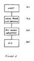
- FIG. 2a process flow chart for a first preferred method of this invention.
- FIG. 3is a process flow chart for a second preferred method of this invention.
- This inventionis a system and method for detecting and matching impedance in a power line communication channel, to provide maximum power transfer to and from the power line for both transmission and reception of the communication signal, as well as minimizing the radiated power off the power lien and the reflection coefficient.
- this inventionuses circuitry and a method incorporated in a power line phone jack to sense the impedance of the power line and correct the input and/or output stages of the power line interface to match the impedance of the power line.
- the method of this inventioncan be done as frequently or infrequently as needed, for example, the transceiver connected to the power line can sense and match the power line impedance only when first plugged in or many times per power line cycle.
- FIG. 1shows a top-level block diagram of the preferred impedance matching system of this invention.
- the automatic power line impedance matching of this inventionis preferably built into a standard power line telephone jack 100 .
- the existing jack circuitry 101is electrically 104 connected to an adjustable source impedance circuit 102 , the output of which is connected to the AC power line 108 .
- the preferred source impedance circuit 102is a voltage adjustable series resistor.
- the AC power line 108is provided with a detection point 107 where the signal level can be measured.
- the AC power line 108is also connected to the line detection circuit 103 where the power line impedance detection is performed.
- the power line level detection circuit 103communicates 105 the desired impedance for matching to the source impedance circuit 102 .
- One preferred method of controlling the variable resistance of the source impedance 102is to use a transistor as the variable resistor of the source impedance 102 , similar to an automatic gain control circuit, well known in the art.
- the transistoris controlled by the value of the signal at the output of the source impedance 102 .
- the best and preferred impedance matchis accomplished when the voltage level measured at the output of the source impedance 102 is equal to 1 ⁇ 2 of the voltage on the input to the series resistor of the source impedance 102 . This means that the best match is achieved when the source impedance 102 and the load impedance of the telephone line 108 is equal.
- FIG. 2shows a process flow chart for a first preferred method of this invention.
- This preferred methodstarts 201 by outputting 202 a tone.
- the voltage levelis measured 203 at the output of the source impedance 102 to the power line 108 and the series resistance is adjusted 204 to give the match.
- the best possible matchis set 205 , completing the adjustment of the series resistance ends 206 this preferred embodiment of the process.
- FIG. 3shows a process flow chart for a second automatic preferred method of this invention.
- the processstarts 301 with the sensing 302 of the AC power line impedance. Then the variable resistance of the source impedance 102 is adjusted 303 . Once the source impedance 102 is adjusted the process ends 304 .
Landscapes
- Engineering & Computer Science (AREA)
- Power Engineering (AREA)
- Computer Networks & Wireless Communication (AREA)
- Signal Processing (AREA)
- Cable Transmission Systems, Equalization Of Radio And Reduction Of Echo (AREA)
Abstract
Description
Claims (3)
Priority Applications (3)
| Application Number | Priority Date | Filing Date | Title |
|---|---|---|---|
| US09/552,513US6515485B1 (en) | 2000-04-19 | 2000-04-19 | Method and system for power line impedance detection and automatic impedance matching |
| PCT/US2001/012437WO2001081938A1 (en) | 2000-04-19 | 2001-04-17 | Method and system for power line impedance detection and automatic impedance matching |
| AU2001253579AAU2001253579A1 (en) | 2000-04-19 | 2001-04-17 | Method and system for power line impedance detection and automatic impedance matching |
Applications Claiming Priority (1)
| Application Number | Priority Date | Filing Date | Title |
|---|---|---|---|
| US09/552,513US6515485B1 (en) | 2000-04-19 | 2000-04-19 | Method and system for power line impedance detection and automatic impedance matching |
Publications (1)
| Publication Number | Publication Date |
|---|---|
| US6515485B1true US6515485B1 (en) | 2003-02-04 |
Family
ID=24205659
Family Applications (1)
| Application Number | Title | Priority Date | Filing Date |
|---|---|---|---|
| US09/552,513Expired - Fee RelatedUS6515485B1 (en) | 2000-04-19 | 2000-04-19 | Method and system for power line impedance detection and automatic impedance matching |
Country Status (3)
| Country | Link |
|---|---|
| US (1) | US6515485B1 (en) |
| AU (1) | AU2001253579A1 (en) |
| WO (1) | WO2001081938A1 (en) |
Cited By (47)
| Publication number | Priority date | Publication date | Assignee | Title |
|---|---|---|---|---|
| US20010045888A1 (en)* | 2000-01-20 | 2001-11-29 | Kline Paul A. | Method of isolating data in a power line communications network |
| US20020002040A1 (en)* | 2000-04-19 | 2002-01-03 | Kline Paul A. | Method and apparatus for interfacing RF signals to medium voltage power lines |
| US20020110310A1 (en)* | 2001-02-14 | 2002-08-15 | Kline Paul A. | Method and apparatus for providing inductive coupling and decoupling of high-frequency, high-bandwidth data signals directly on and off of a high voltage power line |
| US20020121963A1 (en)* | 2001-02-14 | 2002-09-05 | Kline Paul A. | Data communication over a power line |
| US20030179080A1 (en)* | 2001-12-21 | 2003-09-25 | Mollenkopf James Douglas | Facilitating communication of data signals on electric power systems |
| US20030234713A1 (en)* | 2002-06-21 | 2003-12-25 | Pridmore Charles Franklin | Power line coupling device and method of using the same |
| US20040003934A1 (en)* | 2002-06-24 | 2004-01-08 | Cope Leonard David | Power line coupling device and method of using the same |
| US20040056734A1 (en)* | 2001-05-18 | 2004-03-25 | Davidow Clifford A. | Medium voltage signal coupling structure for last leg power grid high-speed data network |
| US20040109499A1 (en)* | 2002-11-06 | 2004-06-10 | Ambient Corporation | Controlling power output of a modem for power line communications |
| US20040110483A1 (en)* | 2002-12-10 | 2004-06-10 | Mollenkopf James Douglas | Power line communication sytem and method |
| US20040113756A1 (en)* | 2002-12-10 | 2004-06-17 | Mollenkopf James Douglas | Device and method for coupling with electrical distribution network infrastructure to provide communications |
| US20040113757A1 (en)* | 2002-12-10 | 2004-06-17 | White Melvin Joseph | Power line communication system and method of operating the same |
| US20040135676A1 (en)* | 2002-12-10 | 2004-07-15 | Berkman William H. | Power line communication system and method of operating the same |
| US20040142599A1 (en)* | 2003-01-21 | 2004-07-22 | Cope Leonard D. | Power line coupling device and method of using the same |
| US20040227622A1 (en)* | 2003-05-13 | 2004-11-18 | Giannini Paul M. | Device and method for communicating data signals through multiple power line conductors |
| US20040227621A1 (en)* | 2000-04-14 | 2004-11-18 | Cope Leonard D. | Power line communication apparatus and method of using the same |
| US20050157442A1 (en)* | 2004-01-21 | 2005-07-21 | Evans Wetmore | System and method for distributing broadband communication signals over power lines |
| US20050194838A1 (en)* | 2004-03-03 | 2005-09-08 | Evans Wetmore | System and method for reducing radiation when distributing broadband communication signals over power lines |
| US20050206507A1 (en)* | 2000-04-14 | 2005-09-22 | Kline Paul A | Power line communication system and method |
| US20060066321A1 (en)* | 2004-09-30 | 2006-03-30 | Gasperi Michael L | AC power line impedance monitoring method and system |
| US20060114925A1 (en)* | 2004-12-01 | 2006-06-01 | At&T Corp. | Interference control in a broadband powerline communication system |
| US20060125609A1 (en)* | 2000-08-09 | 2006-06-15 | Kline Paul A | Power line coupling device and method of using the same |
| US7091849B1 (en) | 2004-05-06 | 2006-08-15 | At&T Corp. | Inbound interference reduction in a broadband powerline system |
| US7113134B1 (en) | 2004-03-12 | 2006-09-26 | Current Technologies, Llc | Transformer antenna device and method of using the same |
| US20060229834A1 (en)* | 2005-03-30 | 2006-10-12 | Gasperi Michael L | Dual connection power line parameter analysis method and system |
| US20060229831A1 (en)* | 2005-03-30 | 2006-10-12 | Gasperi Michael L | Power line parameter analysis method and system |
| US20060241881A1 (en)* | 2005-03-30 | 2006-10-26 | Gasperi Michael L | Networked power line parameter analysis method and system |
| US20060244571A1 (en)* | 2005-04-29 | 2006-11-02 | Yaney David S | Power line coupling device and method of use |
| US7132819B1 (en) | 2002-11-12 | 2006-11-07 | Current Technologies, Llc | Floating power supply and method of using the same |
| US20060281359A1 (en)* | 2004-11-03 | 2006-12-14 | Panduit Corp. | Method and apparatus for reliable network cable connectivity |
| US7173938B1 (en) | 2001-05-18 | 2007-02-06 | Current Grid, Llc | Method and apparatus for processing outbound data within a powerline based communication system |
| US7194528B1 (en)* | 2001-05-18 | 2007-03-20 | Current Grid, Llc | Method and apparatus for processing inbound data within a powerline based communication system |
| US7245201B1 (en) | 2000-08-09 | 2007-07-17 | Current Technologies, Llc | Power line coupling device and method of using the same |
| US20080265912A1 (en)* | 2007-04-30 | 2008-10-30 | Rockwell Automation Technologies, Inc. | Portable line impedance measurement method and system |
| US20080265910A1 (en)* | 2007-04-30 | 2008-10-30 | Rockwell Automation Technologies, Inc. | Line impedance measurement method and system |
| US7460467B1 (en) | 2003-07-23 | 2008-12-02 | Current Technologies, Llc | Voice-over-IP network test device and method |
| US20090002094A1 (en)* | 2007-06-26 | 2009-01-01 | Radtke William O | Power Line Coupling Device and Method |
| US20090002137A1 (en)* | 2007-06-26 | 2009-01-01 | Radtke William O | Power Line Coupling Device and Method |
| US20090085726A1 (en)* | 2007-09-27 | 2009-04-02 | Radtke William O | Power Line Communications Coupling Device and Method |
| US7852837B1 (en) | 2003-12-24 | 2010-12-14 | At&T Intellectual Property Ii, L.P. | Wi-Fi/BPL dual mode repeaters for power line networks |
| US20120074952A1 (en)* | 2010-09-24 | 2012-03-29 | Chappell Daniel K | Home network characterization method and system |
| US20120286805A1 (en)* | 2009-11-27 | 2012-11-15 | Dominic Maurath | Loading state determiner, load assembly, power supply circuit and method for determining a loading state of an electric power source |
| US8462902B1 (en) | 2004-12-01 | 2013-06-11 | At&T Intellectual Property Ii, L.P. | Interference control in a broadband powerline communication system |
| US20130234804A1 (en)* | 2010-11-15 | 2013-09-12 | Zte Corporation | Method and Circuitry for Matching Impedance |
| US8923339B2 (en) | 2011-03-06 | 2014-12-30 | PCN Technology, Inc. | Systems and methods of data transmission and management |
| US9143112B2 (en) | 2011-06-30 | 2015-09-22 | Silicon Laboratories Inc. | Circuits and methods for providing an impedance adjustment |
| US9778296B2 (en) | 2014-08-14 | 2017-10-03 | National Chiao Tung University | Method for obtaining plug combination of detecting apparatus and method for obtaining power line topology and electronic apparatus using the same |
Families Citing this family (3)
| Publication number | Priority date | Publication date | Assignee | Title |
|---|---|---|---|---|
| KR100367592B1 (en)* | 2000-05-12 | 2003-01-10 | 엘지전자 주식회사 | Adaptive type power line communication apparatus and method |
| KR20030080963A (en)* | 2002-07-25 | 2003-10-17 | 넷디바이스 주식회사 | Power line communication modem |
| LU100681B1 (en) | 2018-01-25 | 2019-08-21 | Univ Luxembourg | Grid conductance and susceptance estimation for power control in grid-tied inverters |
Citations (7)
| Publication number | Priority date | Publication date | Assignee | Title |
|---|---|---|---|---|
| US3810096A (en) | 1972-09-14 | 1974-05-07 | Integrated Syst Co | Method and system for transmitting data and indicating room status |
| US5349644A (en) | 1992-06-30 | 1994-09-20 | Electronic Innovators, Inc. | Distributed intelligence engineering casualty and damage control management system using an AC power line carrier-current lan |
| US5402073A (en)* | 1992-01-28 | 1995-03-28 | Ross; Alan | Near-end communications line characteristic measuring system with a voltage sensitive non-linear device disposed at the far end |
| US5465287A (en)* | 1994-01-13 | 1995-11-07 | Teledata Communication Ltd. | Subscriber line impedance measurement device and method |
| US5559440A (en)* | 1994-12-22 | 1996-09-24 | Lucent Technologies Inc. | Method and apparatus for testing telecommunications equipment having both analog and digital interfaces |
| US5869909A (en) | 1997-05-08 | 1999-02-09 | ATT Corp--Lucent Technologies Inc | Active ground compensation |
| US5949327A (en) | 1994-08-26 | 1999-09-07 | Norweb Plc | Coupling of telecommunications signals to a balanced power distribution network |
- 2000
- 2000-04-19USUS09/552,513patent/US6515485B1/ennot_activeExpired - Fee Related
- 2001
- 2001-04-17AUAU2001253579Apatent/AU2001253579A1/ennot_activeAbandoned
- 2001-04-17WOPCT/US2001/012437patent/WO2001081938A1/enactiveApplication Filing
Patent Citations (7)
| Publication number | Priority date | Publication date | Assignee | Title |
|---|---|---|---|---|
| US3810096A (en) | 1972-09-14 | 1974-05-07 | Integrated Syst Co | Method and system for transmitting data and indicating room status |
| US5402073A (en)* | 1992-01-28 | 1995-03-28 | Ross; Alan | Near-end communications line characteristic measuring system with a voltage sensitive non-linear device disposed at the far end |
| US5349644A (en) | 1992-06-30 | 1994-09-20 | Electronic Innovators, Inc. | Distributed intelligence engineering casualty and damage control management system using an AC power line carrier-current lan |
| US5465287A (en)* | 1994-01-13 | 1995-11-07 | Teledata Communication Ltd. | Subscriber line impedance measurement device and method |
| US5949327A (en) | 1994-08-26 | 1999-09-07 | Norweb Plc | Coupling of telecommunications signals to a balanced power distribution network |
| US5559440A (en)* | 1994-12-22 | 1996-09-24 | Lucent Technologies Inc. | Method and apparatus for testing telecommunications equipment having both analog and digital interfaces |
| US5869909A (en) | 1997-05-08 | 1999-02-09 | ATT Corp--Lucent Technologies Inc | Active ground compensation |
Cited By (112)
| Publication number | Priority date | Publication date | Assignee | Title |
|---|---|---|---|---|
| US6977578B2 (en) | 2000-01-20 | 2005-12-20 | Current Technologies, Llc | Method of isolating data in a power line communications network |
| US20010045888A1 (en)* | 2000-01-20 | 2001-11-29 | Kline Paul A. | Method of isolating data in a power line communications network |
| US7245212B2 (en) | 2000-04-14 | 2007-07-17 | Current Technologies, Llc | Power line communication apparatus and method of using the same |
| US20050285720A1 (en)* | 2000-04-14 | 2005-12-29 | Cope Leonard D | Power line communication apparatus and method of using the same |
| US6958680B2 (en) | 2000-04-14 | 2005-10-25 | Current Technologies, Llc | Power line communication system and method of using the same |
| US20050206507A1 (en)* | 2000-04-14 | 2005-09-22 | Kline Paul A | Power line communication system and method |
| US6998962B2 (en) | 2000-04-14 | 2006-02-14 | Current Technologies, Llc | Power line communication apparatus and method of using the same |
| US20040227621A1 (en)* | 2000-04-14 | 2004-11-18 | Cope Leonard D. | Power line communication apparatus and method of using the same |
| US7307511B2 (en) | 2000-04-14 | 2007-12-11 | Current Technologies, Llc | Power line communication system and method |
| US20020002040A1 (en)* | 2000-04-19 | 2002-01-03 | Kline Paul A. | Method and apparatus for interfacing RF signals to medium voltage power lines |
| US7245201B1 (en) | 2000-08-09 | 2007-07-17 | Current Technologies, Llc | Power line coupling device and method of using the same |
| US7248148B2 (en) | 2000-08-09 | 2007-07-24 | Current Technologies, Llc | Power line coupling device and method of using the same |
| US20060125609A1 (en)* | 2000-08-09 | 2006-06-15 | Kline Paul A | Power line coupling device and method of using the same |
| US20030190110A1 (en)* | 2001-02-14 | 2003-10-09 | Kline Paul A. | Method and apparatus for providing inductive coupling and decoupling of high-frequency, high-bandwidth data signals directly on and off of a high voltage power line |
| US7414518B2 (en) | 2001-02-14 | 2008-08-19 | Current Technologies, Llc | Power line communication device and method |
| US20070287406A1 (en)* | 2001-02-14 | 2007-12-13 | Kline Paul A | Data Communication over a Power Line |
| US7453352B2 (en) | 2001-02-14 | 2008-11-18 | Current Technologies, Llc | Data communication over a power line |
| US7103240B2 (en) | 2001-02-14 | 2006-09-05 | Current Technologies, Llc | Method and apparatus for providing inductive coupling and decoupling of high-frequency, high-bandwidth data signals directly on and off of a high voltage power line |
| US20060171174A1 (en)* | 2001-02-14 | 2006-08-03 | Kline Paul A | Data communication over a power line |
| US6933835B2 (en) | 2001-02-14 | 2005-08-23 | Current Technologies, Llc | Data communication over a power line |
| US7042351B2 (en) | 2001-02-14 | 2006-05-09 | Current Technologies, Llc | Data communication over a power line |
| US7218219B2 (en) | 2001-02-14 | 2007-05-15 | Current Technologies, Llc | Data communication over a power line |
| US6950567B2 (en) | 2001-02-14 | 2005-09-27 | Current Technologies, Llc | Method and apparatus for providing inductive coupling and decoupling of high-frequency, high-bandwidth data signals directly on and off of a high voltage power line |
| US20020154000A1 (en)* | 2001-02-14 | 2002-10-24 | Kline Paul A. | Data communication over a power line |
| US20020121963A1 (en)* | 2001-02-14 | 2002-09-05 | Kline Paul A. | Data communication over a power line |
| US20020110310A1 (en)* | 2001-02-14 | 2002-08-15 | Kline Paul A. | Method and apparatus for providing inductive coupling and decoupling of high-frequency, high-bandwidth data signals directly on and off of a high voltage power line |
| US20040056734A1 (en)* | 2001-05-18 | 2004-03-25 | Davidow Clifford A. | Medium voltage signal coupling structure for last leg power grid high-speed data network |
| US20070222637A1 (en)* | 2001-05-18 | 2007-09-27 | Davidow Clifford A | Medium Voltage Signal Coupling Structure For Last Leg Power Grid High-Speed Data Network |
| US7245472B2 (en) | 2001-05-18 | 2007-07-17 | Curretn Grid, Llc | Medium voltage signal coupling structure for last leg power grid high-speed data network |
| US7173938B1 (en) | 2001-05-18 | 2007-02-06 | Current Grid, Llc | Method and apparatus for processing outbound data within a powerline based communication system |
| US7773361B2 (en) | 2001-05-18 | 2010-08-10 | Current Grid, Llc | Medium voltage signal coupling structure for last leg power grid high-speed data network |
| US7194528B1 (en)* | 2001-05-18 | 2007-03-20 | Current Grid, Llc | Method and apparatus for processing inbound data within a powerline based communication system |
| US7053756B2 (en) | 2001-12-21 | 2006-05-30 | Current Technologies, Llc | Facilitating communication of data signals on electric power systems |
| US20030179080A1 (en)* | 2001-12-21 | 2003-09-25 | Mollenkopf James Douglas | Facilitating communication of data signals on electric power systems |
| US7102478B2 (en) | 2002-06-21 | 2006-09-05 | Current Technologies, Llc | Power line coupling device and method of using the same |
| US20030234713A1 (en)* | 2002-06-21 | 2003-12-25 | Pridmore Charles Franklin | Power line coupling device and method of using the same |
| US6982611B2 (en) | 2002-06-24 | 2006-01-03 | Current Technologies, Llc | Power line coupling device and method of using the same |
| US7224243B2 (en) | 2002-06-24 | 2007-05-29 | Current Technologies, Llc | Power line coupling device and method of using the same |
| US20060012449A1 (en)* | 2002-06-24 | 2006-01-19 | Cope Leonard D | Power line coupling device and method of using the same |
| US20040003934A1 (en)* | 2002-06-24 | 2004-01-08 | Cope Leonard David | Power line coupling device and method of using the same |
| US7378944B2 (en)* | 2002-11-06 | 2008-05-27 | Ambient Corporation | Controlling power output of a modem for power line communications |
| US20040109499A1 (en)* | 2002-11-06 | 2004-06-10 | Ambient Corporation | Controlling power output of a modem for power line communications |
| US7132819B1 (en) | 2002-11-12 | 2006-11-07 | Current Technologies, Llc | Floating power supply and method of using the same |
| US6980091B2 (en) | 2002-12-10 | 2005-12-27 | Current Technologies, Llc | Power line communication system and method of operating the same |
| US7301440B2 (en) | 2002-12-10 | 2007-11-27 | Current Technologies, Llc | Power line communication system and method |
| US20040110483A1 (en)* | 2002-12-10 | 2004-06-10 | Mollenkopf James Douglas | Power line communication sytem and method |
| US7701325B2 (en) | 2002-12-10 | 2010-04-20 | Current Technologies, Llc | Power line communication apparatus and method of using the same |
| US20040113756A1 (en)* | 2002-12-10 | 2004-06-17 | Mollenkopf James Douglas | Device and method for coupling with electrical distribution network infrastructure to provide communications |
| US20040113757A1 (en)* | 2002-12-10 | 2004-06-17 | White Melvin Joseph | Power line communication system and method of operating the same |
| US20040135676A1 (en)* | 2002-12-10 | 2004-07-15 | Berkman William H. | Power line communication system and method of operating the same |
| US20050273282A1 (en)* | 2002-12-10 | 2005-12-08 | Mollenkopf James D | Power line communication system and method |
| US6965303B2 (en) | 2002-12-10 | 2005-11-15 | Current Technologies, Llc | Power line communication system and method |
| US7064654B2 (en) | 2002-12-10 | 2006-06-20 | Current Technologies, Llc | Power line communication system and method of operating the same |
| US6980090B2 (en) | 2002-12-10 | 2005-12-27 | Current Technologies, Llc | Device and method for coupling with electrical distribution network infrastructure to provide communications |
| US7250848B2 (en) | 2002-12-10 | 2007-07-31 | Current Technologies, Llc | Power line communication apparatus and method of using the same |
| US20040142599A1 (en)* | 2003-01-21 | 2004-07-22 | Cope Leonard D. | Power line coupling device and method of using the same |
| US7046124B2 (en) | 2003-01-21 | 2006-05-16 | Current Technologies, Llc | Power line coupling device and method of using the same |
| US7075414B2 (en) | 2003-05-13 | 2006-07-11 | Current Technologies, Llc | Device and method for communicating data signals through multiple power line conductors |
| US20040227622A1 (en)* | 2003-05-13 | 2004-11-18 | Giannini Paul M. | Device and method for communicating data signals through multiple power line conductors |
| US7460467B1 (en) | 2003-07-23 | 2008-12-02 | Current Technologies, Llc | Voice-over-IP network test device and method |
| US7852837B1 (en) | 2003-12-24 | 2010-12-14 | At&T Intellectual Property Ii, L.P. | Wi-Fi/BPL dual mode repeaters for power line networks |
| US10728127B2 (en) | 2003-12-24 | 2020-07-28 | At&T Intellectual Property Ii, L.P. | Wi-Fi/BPL dual mode repeaters for power line networks |
| US20050157442A1 (en)* | 2004-01-21 | 2005-07-21 | Evans Wetmore | System and method for distributing broadband communication signals over power lines |
| US7079012B2 (en) | 2004-01-21 | 2006-07-18 | Evans Wetmore | System and method for distributing broadband communication signals over power lines |
| US7088232B2 (en) | 2004-03-03 | 2006-08-08 | Evans Wetmore | System and method for reducing radiation when distributing broadband communication signals over power lines |
| US20050194838A1 (en)* | 2004-03-03 | 2005-09-08 | Evans Wetmore | System and method for reducing radiation when distributing broadband communication signals over power lines |
| US7113134B1 (en) | 2004-03-12 | 2006-09-26 | Current Technologies, Llc | Transformer antenna device and method of using the same |
| US7091849B1 (en) | 2004-05-06 | 2006-08-15 | At&T Corp. | Inbound interference reduction in a broadband powerline system |
| US10312965B2 (en) | 2004-05-06 | 2019-06-04 | At&T Intellectual Property Ii, L.P. | Outbound interference reduction in a broadband powerline system |
| US10700737B2 (en) | 2004-05-06 | 2020-06-30 | At&T Intellectual Property Ii, L.P. | Outbound interference reduction in a broadband powerline system |
| US9887734B2 (en) | 2004-05-06 | 2018-02-06 | At&T Intellectual Property Ii, L.P. | Outbound interference reduction in a broadband powerline system |
| US8938021B1 (en) | 2004-05-06 | 2015-01-20 | Paul Shala Henry | Outbound interference reduction in a broadband powerline system |
| US7453353B1 (en) | 2004-05-06 | 2008-11-18 | At&T Intellectual Property Ii, L.P. | Inbound interference reduction in a broadband powerline system |
| US9577706B2 (en) | 2004-05-06 | 2017-02-21 | At&T Intellectual Property Ii, L.P. | Outbound interference reduction in a broadband powerline system |
| US20060066321A1 (en)* | 2004-09-30 | 2006-03-30 | Gasperi Michael L | AC power line impedance monitoring method and system |
| US7164275B2 (en) | 2004-09-30 | 2007-01-16 | Rockwell Automation Technologies, Inc. | AC power line impedance monitoring method and system |
| US20060281359A1 (en)* | 2004-11-03 | 2006-12-14 | Panduit Corp. | Method and apparatus for reliable network cable connectivity |
| US7411405B2 (en) | 2004-11-03 | 2008-08-12 | Panduit Corp. | Method and apparatus for reliable network cable connectivity |
| US9172429B2 (en) | 2004-12-01 | 2015-10-27 | At&T Intellectual Property Ii, L.P. | Interference control in a broadband powerline communication system |
| US9780835B2 (en) | 2004-12-01 | 2017-10-03 | At&T Intellectual Property Ii, L.P. | Interference control in a broadband powerline communication system |
| US8804797B2 (en) | 2004-12-01 | 2014-08-12 | At&T Intellectual Property Ii, L.P. | Interference control in a broadband powerline communication system |
| US8462902B1 (en) | 2004-12-01 | 2013-06-11 | At&T Intellectual Property Ii, L.P. | Interference control in a broadband powerline communication system |
| US10263666B2 (en) | 2004-12-01 | 2019-04-16 | At&T Intellectual Property Ii, L.P. | Interference control in a broadband powerline communication system |
| US20060114925A1 (en)* | 2004-12-01 | 2006-06-01 | At&T Corp. | Interference control in a broadband powerline communication system |
| US20080204042A1 (en)* | 2005-03-30 | 2008-08-28 | Rockwell Automation Technologies, Inc. | Networked power line parameter analysis method and system |
| US7777498B2 (en)* | 2005-03-30 | 2010-08-17 | Rockwell Automation Technologies, Inc. | Networked power line parameter analysis method and system |
| US7200502B2 (en) | 2005-03-30 | 2007-04-03 | Rockwell Automation Technologies, Inc. | Dual connection power line parameter analysis method and system |
| US7526392B2 (en) | 2005-03-30 | 2009-04-28 | Rockwell Automation Technologies, Inc. | Power line parameter analysis method and system |
| US20060241881A1 (en)* | 2005-03-30 | 2006-10-26 | Gasperi Michael L | Networked power line parameter analysis method and system |
| US20060229831A1 (en)* | 2005-03-30 | 2006-10-12 | Gasperi Michael L | Power line parameter analysis method and system |
| US20060229834A1 (en)* | 2005-03-30 | 2006-10-12 | Gasperi Michael L | Dual connection power line parameter analysis method and system |
| US7307512B2 (en) | 2005-04-29 | 2007-12-11 | Current Technologies, Llc | Power line coupling device and method of use |
| US20060244571A1 (en)* | 2005-04-29 | 2006-11-02 | Yaney David S | Power line coupling device and method of use |
| US7671606B2 (en)* | 2007-04-30 | 2010-03-02 | Rockwell Automation Technologies, Inc. | Portable line impedance measurement method and system |
| US7616010B2 (en)* | 2007-04-30 | 2009-11-10 | Rockwell Automation Technologies, Inc. | Line impedance measurement method and system |
| US20080265912A1 (en)* | 2007-04-30 | 2008-10-30 | Rockwell Automation Technologies, Inc. | Portable line impedance measurement method and system |
| US20080265910A1 (en)* | 2007-04-30 | 2008-10-30 | Rockwell Automation Technologies, Inc. | Line impedance measurement method and system |
| US20090002137A1 (en)* | 2007-06-26 | 2009-01-01 | Radtke William O | Power Line Coupling Device and Method |
| US20090002094A1 (en)* | 2007-06-26 | 2009-01-01 | Radtke William O | Power Line Coupling Device and Method |
| US7795994B2 (en) | 2007-06-26 | 2010-09-14 | Current Technologies, Llc | Power line coupling device and method |
| US7876174B2 (en) | 2007-06-26 | 2011-01-25 | Current Technologies, Llc | Power line coupling device and method |
| US20090085726A1 (en)* | 2007-09-27 | 2009-04-02 | Radtke William O | Power Line Communications Coupling Device and Method |
| US9121912B2 (en)* | 2009-11-27 | 2015-09-01 | Hahn-Schickard-Gesellschaft Fuer Angewandte Forschung E.V. | Loading state determiner, load assembly, power supply circuit and method for determining a loading state of an electric power source |
| US20120286805A1 (en)* | 2009-11-27 | 2012-11-15 | Dominic Maurath | Loading state determiner, load assembly, power supply circuit and method for determining a loading state of an electric power source |
| US20120074952A1 (en)* | 2010-09-24 | 2012-03-29 | Chappell Daniel K | Home network characterization method and system |
| US8558552B2 (en)* | 2010-09-24 | 2013-10-15 | Jds Uniphase Corporation | Home network characterization method and system |
| US8761384B2 (en)* | 2010-11-15 | 2014-06-24 | Zte Corporation | Method and circuitry for matching impedance |
| US20130234804A1 (en)* | 2010-11-15 | 2013-09-12 | Zte Corporation | Method and Circuitry for Matching Impedance |
| US8923339B2 (en) | 2011-03-06 | 2014-12-30 | PCN Technology, Inc. | Systems and methods of data transmission and management |
| US9143112B2 (en) | 2011-06-30 | 2015-09-22 | Silicon Laboratories Inc. | Circuits and methods for providing an impedance adjustment |
| US9793873B2 (en) | 2011-06-30 | 2017-10-17 | Silicon Laboratories Inc. | Circuits and methods for providing an impedance adjustment |
| US9778296B2 (en) | 2014-08-14 | 2017-10-03 | National Chiao Tung University | Method for obtaining plug combination of detecting apparatus and method for obtaining power line topology and electronic apparatus using the same |
Also Published As
| Publication number | Publication date |
|---|---|
| WO2001081938A1 (en) | 2001-11-01 |
| AU2001253579A1 (en) | 2001-11-07 |
Similar Documents
| Publication | Publication Date | Title |
|---|---|---|
| US6515485B1 (en) | Method and system for power line impedance detection and automatic impedance matching | |
| CA1285623C (en) | Apparatus for matching unbalanced r.f. baseband signals to balancedsignals on a twisted two-wire line | |
| US6298046B1 (en) | Adjustable balancing circuit for an adaptive hybrid and method of adjusting the same | |
| US6424221B1 (en) | Programmable gain amplifier for use in data network | |
| US4096362A (en) | Automatic cable balancing network | |
| US20020145443A1 (en) | Active termination network | |
| GB2313263A (en) | Circuit for adjusting transmit power in a radiotelephone | |
| US6917682B2 (en) | Method and device for echo cancelling | |
| US4910768A (en) | Automatic balancing circuit for longitudinal transmission system | |
| US6218872B1 (en) | Line driver with output impedance synthesis | |
| EP0515102B1 (en) | Automatic loss control circuit in a digital loop transmission system | |
| US6686799B2 (en) | Burst mode limiter-amplifier | |
| JP4340012B2 (en) | Transceiver chip for digital transmission system | |
| CN1666445B (en) | Optical receiver circuit | |
| US7577205B1 (en) | Return-loss compliant DSL modem line interface unit with complex termination | |
| KR100367592B1 (en) | Adaptive type power line communication apparatus and method | |
| US6181167B1 (en) | Full duplex CMOS communication | |
| US5887026A (en) | Transmission level setting circuit and modem unit using the same | |
| US6760380B1 (en) | Data transmission apparatus and method | |
| WO2010068349A1 (en) | Method, system, and apparatus for a differential transformer-free hybrid circuit | |
| JP3074920B2 (en) | Transmission signal transceiver and transmission / reception equalization circuit | |
| JP3338812B2 (en) | Mobile communication base station device and automatic impedance matching method thereof | |
| WO2001082576A1 (en) | Method and system for phone line impedance detection and automatic impedance matching | |
| JPS5917735A (en) | Signal processor | |
| KR100309101B1 (en) | Apparatus and method for optimizing hybrid balance and characteristic impedance |
Legal Events
| Date | Code | Title | Description |
|---|---|---|---|
| AS | Assignment | Owner name:PHONEX BROADBAND CORPORATION, UTAH Free format text:ASSIGNMENT OF ASSIGNORS INTEREST;ASSIGNORS:BULLOCK, SCOTT R.;HOOBLER, RYAN;REEL/FRAME:010738/0836 Effective date:20000214 | |
| AS | Assignment | Owner name:SILICON VALLEY BANK, CALIFORNIA Free format text:SECURITY AGREEMENT;ASSIGNOR:PHONEX BROADBAND CORP.;REEL/FRAME:014066/0489 Effective date:20030414 | |
| AS | Assignment | Owner name:PHONEX BROADBAND CORPORATION, UTAH Free format text:RELEASE;ASSIGNOR:SILICON VALLEY BANK;REEL/FRAME:016662/0702 Effective date:20050606 | |
| FPAY | Fee payment | Year of fee payment:4 | |
| FEPP | Fee payment procedure | Free format text:PAYOR NUMBER ASSIGNED (ORIGINAL EVENT CODE: ASPN); ENTITY STATUS OF PATENT OWNER: LARGE ENTITY | |
| AS | Assignment | Owner name:D.P. KELLY & ASSOCIATES, L.P.,ILLINOIS Free format text:SECURITY AGREEMENT;ASSIGNOR:PHONEX BROADBAND CORPORATION;REEL/FRAME:024023/0084 Effective date:20091222 Owner name:D.P. KELLY & ASSOCIATES, L.P., ILLINOIS Free format text:SECURITY AGREEMENT;ASSIGNOR:PHONEX BROADBAND CORPORATION;REEL/FRAME:024023/0084 Effective date:20091222 | |
| FPAY | Fee payment | Year of fee payment:8 | |
| AS | Assignment | Owner name:PHONEX BROADBAND CORPORATION, UTAH Free format text:RELEASE BY SECURED PARTY;ASSIGNOR:D.P. KELLY & ASSOCIATES, L.P.;REEL/FRAME:025680/0653 Effective date:20110112 | |
| FEPP | Fee payment procedure | Free format text:PAT HOLDER NO LONGER CLAIMS SMALL ENTITY STATUS, ENTITY STATUS SET TO UNDISCOUNTED (ORIGINAL EVENT CODE: STOL); ENTITY STATUS OF PATENT OWNER: LARGE ENTITY Free format text:PAYER NUMBER DE-ASSIGNED (ORIGINAL EVENT CODE: RMPN); ENTITY STATUS OF PATENT OWNER: LARGE ENTITY Free format text:PAYOR NUMBER ASSIGNED (ORIGINAL EVENT CODE: ASPN); ENTITY STATUS OF PATENT OWNER: LARGE ENTITY | |
| AS | Assignment | Owner name:PHONEX BROADBAND CORP., UTAH Free format text:RELEASE;ASSIGNOR:SILICON VALLEY BANK;REEL/FRAME:027545/0514 Effective date:20120109 | |
| AS | Assignment | Owner name:PHONEX BROADBAND CORPORATION, UTAH Free format text:RELEASE BY SECURED PARTY;ASSIGNOR:SILICON VALLEY BANK;REEL/FRAME:027612/0279 Effective date:20120120 | |
| AS | Assignment | Owner name:PHONEX BROADBAND CORPORATION, UTAH Free format text:RELEASE BY SECURED PARTY;ASSIGNOR:D.P. KELLY & ASSOCIATES, L.P.;REEL/FRAME:027681/0903 Effective date:20120118 | |
| AS | Assignment | Owner name:LOW ENVIRON AG, LLC, DELAWARE Free format text:ASSIGNMENT OF ASSIGNORS INTEREST;ASSIGNOR:PHONEX BROADBAND CORPORATION;REEL/FRAME:028096/0780 Effective date:20120208 | |
| AS | Assignment | Owner name:PHONEX BROADBAND CORPORATION, A DELAWARE CORPORATI Free format text:MERGER;ASSIGNOR:PHONEX BROADBAND CORPORATION, A UTAH CORPORATION;REEL/FRAME:028559/0594 Effective date:20041007 | |
| AS | Assignment | Owner name:PHONEX BROADBAND CORPORATION, UTAH Free format text:CORRECTIVE ASSIGNMENT TO CORRECT THE SECOND INVENTOR'S EXECUTION DATE PREVIOUSLY RECORDED ON REEL 010738 FRAME 0836. ASSIGNOR(S) HEREBY CONFIRMS THE SECOND INVENTOR'S EXECUTION DATE IS 02/11/2000, NOT 02/14/2000;ASSIGNORS:BULLOCK, SCOTT R.;HOOBLER, RYAN;SIGNING DATES FROM 20000211 TO 20000214;REEL/FRAME:028791/0574 | |
| REMI | Maintenance fee reminder mailed | ||
| LAPS | Lapse for failure to pay maintenance fees | ||
| STCH | Information on status: patent discontinuation | Free format text:PATENT EXPIRED DUE TO NONPAYMENT OF MAINTENANCE FEES UNDER 37 CFR 1.362 | |
| FP | Lapsed due to failure to pay maintenance fee | Effective date:20150204 |