US6514281B1 - System for delivering bifurcation stents - Google Patents
System for delivering bifurcation stentsDownload PDFInfo
- Publication number
- US6514281B1 US6514281B1US09/148,179US14817998AUS6514281B1US 6514281 B1US6514281 B1US 6514281B1US 14817998 AUS14817998 AUS 14817998AUS 6514281 B1US6514281 B1US 6514281B1
- Authority
- US
- United States
- Prior art keywords
- stent
- branch
- elongate
- deployment system
- sheath
- Prior art date
- Legal status (The legal status is an assumption and is not a legal conclusion. Google has not performed a legal analysis and makes no representation as to the accuracy of the status listed.)
- Expired - Fee Related
Links
Images


Classifications
- A—HUMAN NECESSITIES
- A61—MEDICAL OR VETERINARY SCIENCE; HYGIENE
- A61F—FILTERS IMPLANTABLE INTO BLOOD VESSELS; PROSTHESES; DEVICES PROVIDING PATENCY TO, OR PREVENTING COLLAPSING OF, TUBULAR STRUCTURES OF THE BODY, e.g. STENTS; ORTHOPAEDIC, NURSING OR CONTRACEPTIVE DEVICES; FOMENTATION; TREATMENT OR PROTECTION OF EYES OR EARS; BANDAGES, DRESSINGS OR ABSORBENT PADS; FIRST-AID KITS
- A61F2/00—Filters implantable into blood vessels; Prostheses, i.e. artificial substitutes or replacements for parts of the body; Appliances for connecting them with the body; Devices providing patency to, or preventing collapsing of, tubular structures of the body, e.g. stents
- A61F2/95—Instruments specially adapted for placement or removal of stents or stent-grafts
- A61F2/954—Instruments specially adapted for placement or removal of stents or stent-grafts for placing stents or stent-grafts in a bifurcation
- A—HUMAN NECESSITIES
- A61—MEDICAL OR VETERINARY SCIENCE; HYGIENE
- A61F—FILTERS IMPLANTABLE INTO BLOOD VESSELS; PROSTHESES; DEVICES PROVIDING PATENCY TO, OR PREVENTING COLLAPSING OF, TUBULAR STRUCTURES OF THE BODY, e.g. STENTS; ORTHOPAEDIC, NURSING OR CONTRACEPTIVE DEVICES; FOMENTATION; TREATMENT OR PROTECTION OF EYES OR EARS; BANDAGES, DRESSINGS OR ABSORBENT PADS; FIRST-AID KITS
- A61F2/00—Filters implantable into blood vessels; Prostheses, i.e. artificial substitutes or replacements for parts of the body; Appliances for connecting them with the body; Devices providing patency to, or preventing collapsing of, tubular structures of the body, e.g. stents
- A61F2/82—Devices providing patency to, or preventing collapsing of, tubular structures of the body, e.g. stents
- A61F2/856—Single tubular stent with a side portal passage
- A—HUMAN NECESSITIES
- A61—MEDICAL OR VETERINARY SCIENCE; HYGIENE
- A61F—FILTERS IMPLANTABLE INTO BLOOD VESSELS; PROSTHESES; DEVICES PROVIDING PATENCY TO, OR PREVENTING COLLAPSING OF, TUBULAR STRUCTURES OF THE BODY, e.g. STENTS; ORTHOPAEDIC, NURSING OR CONTRACEPTIVE DEVICES; FOMENTATION; TREATMENT OR PROTECTION OF EYES OR EARS; BANDAGES, DRESSINGS OR ABSORBENT PADS; FIRST-AID KITS
- A61F2/00—Filters implantable into blood vessels; Prostheses, i.e. artificial substitutes or replacements for parts of the body; Appliances for connecting them with the body; Devices providing patency to, or preventing collapsing of, tubular structures of the body, e.g. stents
- A61F2/02—Prostheses implantable into the body
- A61F2/04—Hollow or tubular parts of organs, e.g. bladders, tracheae, bronchi or bile ducts
- A61F2/06—Blood vessels
- A61F2002/065—Y-shaped blood vessels
- A61F2002/067—Y-shaped blood vessels modular
- A—HUMAN NECESSITIES
- A61—MEDICAL OR VETERINARY SCIENCE; HYGIENE
- A61F—FILTERS IMPLANTABLE INTO BLOOD VESSELS; PROSTHESES; DEVICES PROVIDING PATENCY TO, OR PREVENTING COLLAPSING OF, TUBULAR STRUCTURES OF THE BODY, e.g. STENTS; ORTHOPAEDIC, NURSING OR CONTRACEPTIVE DEVICES; FOMENTATION; TREATMENT OR PROTECTION OF EYES OR EARS; BANDAGES, DRESSINGS OR ABSORBENT PADS; FIRST-AID KITS
- A61F2/00—Filters implantable into blood vessels; Prostheses, i.e. artificial substitutes or replacements for parts of the body; Appliances for connecting them with the body; Devices providing patency to, or preventing collapsing of, tubular structures of the body, e.g. stents
- A61F2/95—Instruments specially adapted for placement or removal of stents or stent-grafts
- A61F2002/9505—Instruments specially adapted for placement or removal of stents or stent-grafts having retaining means other than an outer sleeve, e.g. male-female connector between stent and instrument
- A61F2002/9511—Instruments specially adapted for placement or removal of stents or stent-grafts having retaining means other than an outer sleeve, e.g. male-female connector between stent and instrument the retaining means being filaments or wires
- A—HUMAN NECESSITIES
- A61—MEDICAL OR VETERINARY SCIENCE; HYGIENE
- A61F—FILTERS IMPLANTABLE INTO BLOOD VESSELS; PROSTHESES; DEVICES PROVIDING PATENCY TO, OR PREVENTING COLLAPSING OF, TUBULAR STRUCTURES OF THE BODY, e.g. STENTS; ORTHOPAEDIC, NURSING OR CONTRACEPTIVE DEVICES; FOMENTATION; TREATMENT OR PROTECTION OF EYES OR EARS; BANDAGES, DRESSINGS OR ABSORBENT PADS; FIRST-AID KITS
- A61F2/00—Filters implantable into blood vessels; Prostheses, i.e. artificial substitutes or replacements for parts of the body; Appliances for connecting them with the body; Devices providing patency to, or preventing collapsing of, tubular structures of the body, e.g. stents
- A61F2/95—Instruments specially adapted for placement or removal of stents or stent-grafts
- A61F2/962—Instruments specially adapted for placement or removal of stents or stent-grafts having an outer sleeve
- A61F2002/9623—Instruments specially adapted for placement or removal of stents or stent-grafts having an outer sleeve the sleeve being reinforced
Definitions
- the present inventionrelates to a system for treating vascular disease. More specifically, the present invention relates to a system for deploying a stent in a bifurcation lesion. It is also contemplated that the present invention may be useful in AAA graft delivery.
- vascular diseasecurrently represents a prevalent medical condition. Typical vascular disease involves the development of a stenosis in the vasculature. The particular vessel containing the stenosis can be completely blocked (or occluded) or it can simply be narrowed (or restricted). In either case, restriction of the vessel caused by the stenotic lesion results in many well known problems caused by the reduction or cessation of blood flow through the restricted vessel.
- a bifurcationis an area of the vasculature where a first (or parent) vessel is bifurcated into two or more branch vessels. It is not uncommon for stenotic lesions to form in such bifurcations. The stenotic lesions can affect only one of the vessels (i.e., either of the branch vessels or the parent vessel) two of the vessels, or all three vessels.
- Vascular stentsare also currently well known.
- Vascular stentstypically involve a tubular stent which is movable from a collapsed, low profile, delivery position to an expanded, deployed position.
- the stentis typically delivered using a stent delivery device, such as a stent delivery catheter.
- the stentis crimped down to its delivery position over an expandable element, such as a stent deployment balloon.
- the stentis then advanced using the catheter attached to the stent deployment balloon to the lesion site under any suitable, commonly known visualization technique.
- the balloonis then expanded to drive the stent from its delivery position to its deployed position in which the outer periphery of the stent frictionally engages the inner periphery of the lumen.
- the lumenis predilated using a conventional dilatation catheter, and then the stent is deployed to maintain the vessel in an unoccluded, and unrestricted position.
- Self-expanding stentscan also be used.
- Self-expanding stentsare typically formed of a resilient material.
- some self-expanding stentsare formed of a Nitinol material which is trained to deploy at body temperature.
- other resilient materialscan also be used.
- the resilient materialhas sufficient resilience that it can be collapsed to the low profile position and inserted within a delivery device, such as a catheter. Once the catheter is placed at the site of the stenotic lesion, the stent is pushed from within the catheter such that it is no longer constrained in its low profile position.
- the stentdriven by the resilience of the material, expands to a higher profile, deployed position in which its outer periphery frictionally engages the walls of the stenosed vessel, thereby reducing the restriction in the vessel.
- the treating physicianmust then advance a dilatation balloon between the struts of the stent already deployed in order to dilate the second branch vessel.
- the physicianmay then attempt to maneuver a second stent through the struts of the stent already deployed, into the second branch vessel for deployment.
- This presents significant difficultiesFor example, dilating between the struts of the stent already deployed tends to distort that stent.
- deploying the second stent through the struts of the first stentis not only difficult, but it can also distort the first stent.
- the current systems used to alternately deploy stents in a bifurcated lesionhave significant disadvantages.
- a stent deployment systemincludes a tubular member having a first end and a second end and a generally longitudinal opening between the first and second ends.
- the tubular memberhas an inner periphery sized to receive a stent therein.
- a plurality of aperturesare disposed on opposite sides of the generally longitudinal opening.
- An elongate retaineris removably receivable within the apertures to retain the stent in the tubular member and to release the stent from the tubular member when removed from the apertures.
- FIG. 1illustrates a typical bifurcation lesion.
- FIGS. 2A-2Dillustrate one embodiment of a stent deployment system in accordance with one aspect of the present invention.
- FIGS. 2E-2Gillustrate various stents for use in the present invention.
- FIGS. 3A-3Billustrate another embodiment of a stent deployment system in accordance with one aspect of the present invention.
- FIG. 4illustrates another embodiment of a stent deployment system in accordance with the present invention.
- FIG. 5illustrates the formation of a stent deployment sheath in accordance with one aspect of the present invention.
- FIGS. 6A-6Dillustrate the formation of a stent deployment sheath in accordance with another aspect of the present invention.
- FIG. 7illustrates the formation of a stent deployment sheath in accordance with another aspect of the present invention.
- FIGS. 8A-8Cillustrate a stent deployment sheath in accordance with another aspect of the present invention.
- FIGS. 9A-9Fillustrate the operation of a stent deployment sheath in accordance with another aspect of the present invention.
- FIGS. 10A-10Dillustrate a stent deployment system in accordance with another aspect of the present invention.
- FIG. 1illustrates bifurcation 10 which includes parent vessel 12 , first branch vessel 14 and second branch vessel 16 .
- FIG. 1also illustrates that a bifurcation lesion 18 has developed in bifurcation 10 .
- lesion 18extends into both branch vessels 14 and 16 , and extends slightly into parent vessel 12 as well.
- Lesion 18may also be located on only one side of the branch vessel 14 or 16 . In either case, it is preferable to stent both branch vessels 14 and 16 to avoid collapsing one.
- itmay commonly first be predilated with a conventional angioplasty balloon catheter dilatation device.
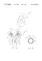
- FIGS. 2A-2Dillustrate the operation of a stent deployment system 20 in accordance with one aspect of the present invention.
- System 20includes a sheath 22 which has a trunk portion 24 , a first branch portion 26 and a second branch portion 28 .
- Sheath 22also includes a proximal withdrawal member 43 which is attached, in one illustrative embodiment, to the proximal end of sheath 22 .
- the withdrawal member 43may be a tube, a wire, a continuation of the sheath 22 , or any other suitable structure.
- branch portions 26 and 28include generally longitudinal openings or slits 30 and 32 , respectively.
- branch portions 26 and 28 of sheath 22also include a plurality of containment rings 34 , each of which have an eyelet 36 and 38 at opposite ends thereof. Rings 34 are disposed about the periphery of branch portions 26 and 28 . In one illustrative embodiment, rings 34 are embedded in the material of branch portions 26 and 28 of sheath 22 . In another illustrative embodiment, rings 34 are adhered to either the exterior or interior surface of the respective branch portions of sheath 22 by a suitable adhesive, by welding, or by other suitable connection mechanisms.
- branch portions 26 and 28 of sheath 22each have, received therein, stents 40 and 42 , respectively.
- Stents 40 and 42may be used in conjunction with a trunk stent portion 41 as illustrated in FIG. 2 E. It is also contemplated that stents 40 and 42 as illustrated in FIG. 2A may be replaced with bifurcated stents 210 a or 210 b as illustrated in FIG. 2 F and FIG. 2 G. However, any of the stents illustrated in FIGS. 2E-2G may be utilized with any of the delivery systems of the present invention.
- Each bifurcated stent 210 a and 210 b and their corresponding partsmay be generically referred to as stent 210 or bifurcated stent 210 .
- bifurcated stent 210 ais utilized.
- stents 40 and 42are self-expanding stents which are retained in a low profile, delivery position within branch portions 26 and 28 , but which can be released from branch portions 26 and 28 to assume a higher profile, deployed position.
- System 20also includes an elongate release member 44 .
- release member 44is simply a wire which has a proximal portion 46 and first and second branch portions 48 and 50 , respectively.
- Branch portions 48 and 50during delivery of legs 212 and 214 of bifurcated stent 210 or during delivery of stents 40 and 42 , are threaded through eyelets 36 and 38 on each of rings 34 to hold the rings together in the lower profile delivery position, thus constraining stents 40 and 42 within branch portions 26 and 28 of sheath 22 , respectively.
- First branch portion 48 and second branch portion 50may be threaded through eyelets 36 and 38 starting with the most proximal eyelets and extending to the most distal eyelets as illustrated in FIG. 2 A.
- the branch portions 48 and 50may be threaded through the most distal eyelets first.
- the branch portions 48 and 50initially extend alongside the eyelets 36 and 38 , then are threaded through the distal most eyelets and advanced to the proximal most eyelets.
- the alternative arrangement of the branch portions 48 and 50causes the proximal portion of the branch portions 26 and 28 of the sheath 22 to open first. This arrangement is contemplated to provide a more accurate deployment of the stents 40 , 42 .
- FIG. 2Bis a greatly enlarged partial cross-sectional view of system 20 , taken along section lines 2 B— 2 B illustrated in FIG. 2 A.
- FIG. 2Billustrates that eyelets 36 and 38 , in the delivery position, overlap one another slightly to form an overlapping region 52 .
- branch portion 48 of retaining member 44is threaded through overlapping region 52 to hold eyelets 36 and 38 together in the position shown in FIG. 2 B. This causes ring 34 to contain branch portion 26 of sheath 22 in a lower profile position, thus holding stent 40 in the lower profile, delivery position.
- system 20is advanced through the vasculature (preferably within a guide catheter) to bifurcation 10 with rings 34 , and hence sheath portions 26 and 28 , in the low profile, delivery position shown in FIG. 2 B.
- Sheath 22is then advanced from within the delivery catheter into the bifurcation 10 .
- proximal portion 46 of retainment wire 44is withdrawn proximally.
- branch portions 48 and 50 of retaining wire 44to be withdrawn proximally, and thus to be withdrawn from the overlapping regions 52 of eyelets 36 and 38 on containment rings 34 . This allows eyelets 36 and 38 to separate from one another under the resilience of stent 40 then contained within the sheath.
- FIG. 2Cillustrates system 20 with retaining wire 44 withdrawn proximally to allow stents 40 and 42 to expand. As stents 40 and 42 expand, they drive sheath portions 26 and 28 open along slits 30 and 32 , respectively.
- FIG. 2Dillustrates system 20 in which sheath 22 has been withdrawn proximally, into the parent vessel 12 of bifurcation 10 , leaving legs 212 and 214 of stent 210 or stents 40 and 42 in the deployed position within the bifurcation. Further withdrawal of member 43 causes deployment of the trunk members 41 , 216 a or 216 b , depending on the type of stent utilized. System 20 can then be removed from the vasculature either within a delivery catheter, or separately therefrom.
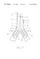
- FIG. 3Aillustrates another embodiment of a stent deployment system 60 in accordance with one aspect of the present invention.
- System 60is formed such that branch sheaths 26 and 28 tend to assume the stent deployment position. In other words, the material is biased such that the distal ends of stents sheaths 26 and 28 tend to diverge from one another.
- system 60is provided with a mechanism by which branch sheaths 26 and 28 can be maintained in an insertion position illustrated in FIG. 3A in which the branch sheaths are maintained closely adjacent one another. In the insertion position, system 60 can be advanced such that its distal end abuts, or is closely adjacent, bifurcation 10 .
- Branch sheaths 26 and 28are then deployed to a stent deployment position in which the branch sheaths assume the position shown in FIG. 2A in which the distal ends of the branch sheaths are separated from one another such that they more closely conform to the shape of bifurcation 10 .
- System 60is provided with an additional elongate member, or wire, 62 .
- additional eyeletsare provided along both of branch sheaths 26 and 28 .
- Elongate wire 62is threaded through the additional eyelets to keep branch sheaths 26 and 28 in the collapsed position shown in FIG. 3 A.
- the branch sheaths 26 and 28are allowed to diverge from one another to the stent deployment position illustrated in FIG. 2 A.
- FIG. 3Bis a greatly enlarged view of system 60 taken along lines 3 B— 3 B illustrated in FIG. 3 A and illustrating an embodiment in which eyelets 36 and 38 are used to maintain sheath 22 in the collapsed position illustrated in FIG. 3 A.
- FIG. 3Billustrates branch sheaths 26 and 28 which are retained by rings 34 .
- the eyelets 36 and 38 attached to the ends of rings 34are simply aligned to form three overlapping regions 66 , 68 and 70 .
- the branch portions 48 and 50 of retaining member 44are threaded therethrough in order to maintain rings 34 in a retaining position about sheaths 26 and 28 .
- the eyelets 36 and 38 associated with rings 34 around both branch sheaths 26 and 28also overlap one another in region 68 .
- elongate wire 62is threaded therethrough in order to maintain the branch sheaths 26 and 28 in close proximity to one another along substantially the entire longitudinal length thereof.
- branch sheaths 26 and 28are allowed to resume their preformed position.
- sheaths 26 and 28are advanced into the branch vessels of bifurcation 10 and retaining member 48 is withdrawn from overlapping regions 66 and 70 allowing sheaths 26 and 28 to open, and thus allowing legs 212 and 214 of stent 210 or stents 40 and 42 to deploy in the branch vessels followed by deployment of trunk portion 41 , 216 a or 216 b depending on the type of stent used.
- FIG. 4illustrates another embodiment of a stent delivery system in accordance with one aspect of the present invention.
- a number of itemsare similar to those shown in previous figures, and are similarly numbered.
- FIG. 4illustrates a system 72 in which a bifurcated stent 74 (shown in phantom) is placed within sheath 22 .
- sheath 22is provided not only with elongate slits or openings 30 and 32 along branch sheaths 26 and 28 , but it is also provided with a trunk slit or opening 76 which is provided along the trunk portion of sheath 22 .
- a plurality of rings 34are therefore also provided around the trunk portion 24 of sheath 22 .
- Rings 34are, as in previous embodiments, provided with eyelets 36 and 38 which overlap one another.
- elongate retaining wire 44is also threaded through eyelets 36 and 38 attached to rings 34 about trunk portion 24 of sheath 22 .
- elongate retaining wire 44is withdrawn proximally, not only do the branch portions 26 and 28 of sheath 22 allow deployment of the branch portions of stent 74 , but the trunk portion allows deployment of the trunk portion of stent 74 as well.
- Sheath 22is then withdrawn using withdrawal member 43 leaving stent 74 in place in bifurcation 10 .
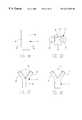
- FIG. 5illustrates one embodiment of the formation of sheath 22 .
- sheath 22is formed of a first section 22 A and a second section 22 B.
- Section 22 Ais simply formed as a rolled sheet which is stamped or preformed in the configuration illustrated in FIG. 5 .
- portion 22 Ahas an elongate longitudinal slit 80 A which runs substantially the entire longitudinal length thereof.
- portion 22 Bis formed identically to portion 22 A, but is simply oriented 180° relative to portion 22 A.
- slits 80 A and 80 Bare generally aligned opposing one another.
- trunk portions of slits 80 A and 80 Bare then attached to one another, such as by heat fusing, a suitable adhesive, welding, or other suitable means, to form the sheath 22 as illustrated in FIG. 2 A.
- rings 34are disposed about branch portions 26 and 28 of sheath 22 .
- rings 34can be embedded in the sheath material at any time during the formation process.
- only one edge of the trunk portion of slits 80 A and 80 Bare fused to one another, leaving slit or opening 76 which extends along the trunk portion of sheath portion 22 as well.
- the slits 80 and the rings 34may be eliminated by embedding the branch portions 48 and 50 of the retaining wire 44 directly into the sheaths 22 along the preferred slit line. By pulling retaining wire 44 embedded in the sheath 22 , the embedded wire tears the sheath to form the desired slits.
- the wire 44 including its branch portions 48 and 50may be embedded in the branch sheaths 26 and 28 only, or in the trunk portion and branch portions.
- FIGS. 6A-6Dillustrate the formation of sheath 22 in accordance with another aspect of the present invention.
- FIG. 6Agenerally illustrates that sheath 22 is first formed as a co-extruded, dual-lumen tube with first lumen 82 and second lumen 84 .
- FIG. 6Bis a cross-sectional view of the co-extruded tube illustrated in FIG. 6A, taken along section lines 6 B— 6 B in FIG. 6 A.
- FIG. 6Billustrates that first lumen 82 and second lumen 84 are separated by a septum 86 .
- the dual extrusioncan be done using any suitable technique.
- septum 86is removed along the branch portions of sheath 22 in the area outlined by dashed line 88 in FIG. 6 B. It should be noted that area 88 includes the entire septum, and also communicates with lumens 82 and 84 . Thus, in the region of branch sheaths 26 and 28 , enough of the septum is removed to form slits 30 and 32 . Thus, sheath 22 is formed as shown in FIG. 6C, with septum 86 being completely removed from leg portions 26 and 28 of sheath 22 .
- Septum 86is then completely removed from the trunk portion of sheath 22 in the region identified by dashed line 90 in FIG. 6 B. It should be noted that the region 90 does not extend all the way to the exterior periphery of sheath 22 , as does area 86 . Thus, there is no external slit running along the trunk portion of sheath 22 . Instead, sheath 22 is formed as illustrated in FIG. 6D, with the trunk portion forming a cylinder. However, if it is desired that sheath 22 be formed as illustrated in the embodiment shown in FIG. 4, then region 90 can be expanded to extend along one edge of the trunk portion of sheath 22 . This provides a slit extending along the trunk portion of sheath 22 , as well as along the branch portions.
- FIG. 7illustrates another embodiment of sheath 22 .
- sheath 22 shown in FIG. 7is formed by simply stamping a single piece of material from sheath stock and rolling the material into the configuration shown in FIG. 7 .
- the configuration shown in FIG. 7provides slits 30 , 32 and 76 which extend along the branch portions 26 and 28 of sheath 22 and which also extend along the trunk portion of sheath 22 as well.
- the edges which define slit 76can be heat fused, or otherwise attached to one another, to eliminate slit 76 .
- FIGS. 8A-8Cillustrate the formation of sheath 22 in accordance with another aspect of the present invention.
- sheath 22is stamped from a single piece of stock material, such as shown in FIG. 7 .
- sheath 22is also provided with stamped, drilled, or cut apertures 92 .
- Apertures 92are disposed generally proximate slits 30 and 32 in the branch portions 26 and 28 of sheath 22 .
- the slots 92are generally aligned with one another along the edges of slots 30 and 32 . Therefore, when slots 30 and 32 are rolled over one another, apertures 92 overlap one another, as shown in FIG. 8B, which is an enlarged view of a portion of branch 26 .
- the branch portion 48 of retaining member 44can be threaded through the overlapping regions 94 to retain the branch portion 26 of sheath 22 in a lower profile configuration, wrapped about stent 40 .
- Branch portion 28is similarly configured.
- retaining member 48is removed or withdrawn from overlapping regions 94 , the branch portion 26 of sheath 22 is free to open, allowing the stent 40 retained therein to deploy in the branch vessel of bifurcation 10 .
- Branch portion 28is similarly manipulated to deploy stent 42 .
- FIG. 8Cillustrates another embodiment in accordance with the present invention.
- the embodiment illustrated in FIG. 8Cis similar to that shown in FIG. 8A in some respects.
- sheath 22 shown in FIG. 8Cis provided with slit 76 similar to that shown in FIG. 7 .
- apertures 92extend all the way from the distal tip of branch portions 26 and 28 of sheath 22 to a proximal end thereof and along the entire length of slit 76 in the trunk portion of sheath 22 .
- elongate retaining member 44can be threaded through the apertures in the trunk portion of sheath 22 as well.
- both the branch portions and the trunk portion of sheath 22are allowed to open and release the stents therein, allowing the stents contained therein to deploy in the bifurcation 10 .
- FIGS. 9A-9Fillustrate stent deployment system 100 in accordance with one aspect of the present invention.
- FIG. 9Aillustrates system 100 in a stent retaining, insertion position.
- System 100includes a stent wrap 102 which has branch portions 104 and 106 , and a trunk portion 108 .
- Branch portions 104 and 106are formed by wrapping a pre-formed flexible material, having ears 110 and 112 , into the position illustrated in FIG. 9 A.
- Ears 110 and 112have apertures 114 and 116 (only one of which is shown in FIG. 9 A). Apertures 114 and 116 are disposed on ears 110 and 112 such that, when ears 110 and 112 are wrapped in the appropriate position, apertures 114 and 116 are generally aligned with, and overlie, one another.
- Apertures 118 and 121extend along trunk portion 108 of wrap 102 . Apertures 118 and 121 are also generally aligned with, and overlie, one another when trunk portion 108 is wrapped as illustrated in FIG. 9 A.
- an elongate retaining membersuch as member 44
- an elongate retaining membercan be threaded through apertures 114 , 116 , 118 and 121 to maintain wrap 102 in the stent retaining position illustrated in FIG. 9 A.
- the retaining member 44allows wrap 102 to unwrap and allows the stents to deploy within the bifurcation 10 .
- FIG. 9Billustrates prestamped wrap 102 in an unwrapped position. It can be seen that the trunk portion 108 of wrap 102 is simply formed in a generally rectangular conformation, which can be rolled such that apertures 118 and 121 are generally overlie one anther. In addition, branch portions 104 and 106 of wrap 102 extend away from trunk portion 108 and can be wrapped about stents to the conformation shown in FIG. 9 A.
- ear 112 of portion 106is first wrapped downwardly and about itself in the direction generally indicated by arrow 120 .
- ear 110is wrapped in the same fashion, in the direction generally indicated by arrow 122 . This results in the conformation generally illustrated in FIG. 9 C.
- ear 112is wrapped about the back portion of both leg portions 104 and 106 in the direction generally indicated by arrow 124 . This results in the conformation generally illustrated in FIG. 9 D.
- Ear 110is then wrapped in a similar fashion as ear 112 , in the direction generally indicated by arrow 126 . This results in the confirmation generally indicated in FIG. 9E, in which ears 110 and 112 overlap one another such that apertures 114 and 116 are generally aligned with one another.
- trunk portion 108The two lateral edges of trunk portion 108 are then wrapped inwardly toward one another in the direction generally indicated by arrows 128 and 130 . The edges are wrapped such that apertures 118 and 121 are in general alignment with one another as illustrated in FIG. 9 F.
- an elongate member(such as member 44 ) is threaded through apertures 114 , 116 , 118 and 121 .
- wrap 102is wrapped in this manner around a bifurcated stent, or individual stents, which are crimped down to the insertion position. Therefore, when the elongate member 44 is withdrawn from the apertures, wrap 102 is allowed to unwrap. The stent or stents are allowed to deploy in bifurcation 10 .
- wrap 102is provided with a proximal withdrawal member 132 .
- Withdrawal member 132is attached to the proximal end of wrap 102 .
- Withdrawal member 132may be a wire, a tube, a continuation of trunk portion 108 , or any other suitable structure.
- wrap 102when wrapped about one or more stents, can be placed in a delivery catheter. Wrap 102 is then advanced, through or within the delivery catheter, to bifurcation 10 and then advanced from within the delivery catheter (such as by pushing on member 132 ) to a deployment position within bifurcation 10 . The elongate member 44 is then withdrawn to deploy the stents as discussed above.
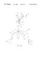
- FIGS. 10A-10Dillustrate a stent deployment system 140 in accordance with another aspect of the present invention.
- FIG. 10Aillustrates system 140 in cross-section and shows that system 140 , in one illustrative embodiment, includes a trunk delivery sheath 142 and a pair of branch delivery sheaths 144 and 146 .
- System 140is illustrated in FIGS. 10A-10D deploying a bifurcated stent 148 which includes a trunk portion 150 and two branch portions 152 and 154 .
- System 140is also illustrated in conjunction with catheter 156 which, in one illustrative embodiment, is a conventional guide catheter, or other catheter sized for use in delivering system 140 to bifurcation 10 .
- System 140also includes, in one illustrative embodiment, a pair of elongate branch deployment members 158 and 160 .
- Elongate members 158 and 160are preferably guidewire tubes defining a guidewire lumen therein for advancement over a conventional guidewire (not shown).
- Catheter 156 and elongate members 158 and 160may be formed of a braided tube to provide sufficient pushability.
- branch deployment member 158is attached to a distal flexible tip 162 on branch delivery sheath 146 .
- Elongate deployment member 160is attached to a distal flexible tip 164 on branch delivery sheath 144 .
- proximal elongate deployment member158 or 160
- distal ends 166 and 168 of deployment members 158 and 160are attached to one another, such as at branching point 170 .
- distal portions 166 and 168may be in the form of a wire or other suitable structure.
- system 140is also, in one illustrative embodiment, provided with a proximal sheath delivery member 172 which is attached to the proximal end of trunk delivery sheath 142 .
- Delivery member 172may be in the form of a wire, tube, a continuation of trunk portion 142 , or any other suitable structure.
- delivery member 172is a braided tube or similar structure.
- Each of the deployment sheaths 142 , 144 and 146preferably have an outer peripheral dimension which fits within the inner peripheral dimension of catheter 156 .
- the inner peripheral dimension of sheaths 142 , 144 and 146is preferably suitable to receive the respective portions of stent 150 , when stent 150 is in the low profile, delivery position.
- sheaths 142 , 144 and 146are preferably withdrawn within the distal end of catheter 156 after stent 148 is placed therein.
- Catheter 156is then advanced to the site of bifurcation 10 within the vasculature.
- Sheaths 142 , 144 and 146are then advanced out through the distal end of catheter 156 by providing a pushing force on elongate member 172 .
- catheter 156may be advanced having sheath 142 protruding out the distal end of catheter 156 such that elongate member 172 is pulled proximally rather than pushed distally.
- branch sheaths 144 and 146are advanced distally using elongate members 158 and 160 .
- the branching portion of stent 148engages the bifurcation 10 such that stent 148 is held in place within the vasculature. Sheaths 144 and 146 are then advanced further until they are advanced completely distally of the branch portions 152 and 154 of stent 148 . This allows the branch portions 152 and 154 to deploy to the radially expanded position illustrated in FIG. 10 B. In the higher profile deployed position, branch members 152 and 154 of stent 148 expand such that they frictionally engage the interior periphery of the branch vessels in bifurcation 10 , thus anchoring stent 148 in place.
- Elongate member 172is then withdrawn proximally. This causes sheath 142 to be withdrawn proximally as well. Since stent 148 is anchored in place by branch portions 152 and 154 , stent 148 remains in place while sheath 142 is withdrawn proximally. This allows sheath 142 to be drawn completely proximally of the proximal end of the trunk portion 150 of stent 148 , thereby allowing trunk portion 150 to expand to the deployed position as illustrated in FIG. 10 C. Stent 148 is thus completely deployed within the bifurcation 10 .
- elongate members 158 and 160are withdrawn proximally such that sheaths 144 and 146 are also withdrawn proximally.
- the external periphery of sheaths 144 and 146is small enough such that it easily fits within the interior periphery of stent 148 , once stent 148 is in the higher profile, deployed position. Therefore, as elongate members 158 and 160 are withdrawn proximally, sheaths 144 and 146 are withdrawn through the interior of stent 148 and within the interior of catheter 156 . This is illustrated by FIG. 10 D.
- System 140is then removed from the vasculature, leaving stent 148 fully deployed.
- the stentscan also be non-self-deploying stents.
- the stentscan be formed of a Nitinol or other suitably resilient material which is trained or otherwise disposed to deploy at body temperature to the higher profile position.
- the stentscan also be crimped down over balloons such that, once placed in a suitable position in the bifurcation, the stents can be deployed by inflating the balloons, in a known manner.
- the present inventionprovides a system for deploying a bifurcated stent which is highly advantageous over prior systems.
Landscapes
- Health & Medical Sciences (AREA)
- Engineering & Computer Science (AREA)
- Biomedical Technology (AREA)
- Cardiology (AREA)
- Oral & Maxillofacial Surgery (AREA)
- Transplantation (AREA)
- Heart & Thoracic Surgery (AREA)
- Vascular Medicine (AREA)
- Life Sciences & Earth Sciences (AREA)
- Animal Behavior & Ethology (AREA)
- General Health & Medical Sciences (AREA)
- Public Health (AREA)
- Veterinary Medicine (AREA)
- Media Introduction/Drainage Providing Device (AREA)
Abstract
Description
The present invention relates to a system for treating vascular disease. More specifically, the present invention relates to a system for deploying a stent in a bifurcation lesion. It is also contemplated that the present invention may be useful in AAA graft delivery.
Vascular disease currently represents a prevalent medical condition. Typical vascular disease involves the development of a stenosis in the vasculature. The particular vessel containing the stenosis can be completely blocked (or occluded) or it can simply be narrowed (or restricted). In either case, restriction of the vessel caused by the stenotic lesion results in many well known problems caused by the reduction or cessation of blood flow through the restricted vessel.
A bifurcation is an area of the vasculature where a first (or parent) vessel is bifurcated into two or more branch vessels. It is not uncommon for stenotic lesions to form in such bifurcations. The stenotic lesions can affect only one of the vessels (i.e., either of the branch vessels or the parent vessel) two of the vessels, or all three vessels.
Vascular stents are also currently well known. Vascular stents typically involve a tubular stent which is movable from a collapsed, low profile, delivery position to an expanded, deployed position. The stent is typically delivered using a stent delivery device, such as a stent delivery catheter. In one common technique, the stent is crimped down to its delivery position over an expandable element, such as a stent deployment balloon. The stent is then advanced using the catheter attached to the stent deployment balloon to the lesion site under any suitable, commonly known visualization technique. The balloon is then expanded to drive the stent from its delivery position to its deployed position in which the outer periphery of the stent frictionally engages the inner periphery of the lumen. In some instances, the lumen is predilated using a conventional dilatation catheter, and then the stent is deployed to maintain the vessel in an unoccluded, and unrestricted position.
Self-expanding stents can also be used. Self-expanding stents are typically formed of a resilient material. For example, some self-expanding stents are formed of a Nitinol material which is trained to deploy at body temperature. However, other resilient materials can also be used. The resilient material has sufficient resilience that it can be collapsed to the low profile position and inserted within a delivery device, such as a catheter. Once the catheter is placed at the site of the stenotic lesion, the stent is pushed from within the catheter such that it is no longer constrained in its low profile position. The stent, driven by the resilience of the material, expands to a higher profile, deployed position in which its outer periphery frictionally engages the walls of the stenosed vessel, thereby reducing the restriction in the vessel.
While there have recently been considerable advances in stent design and stent deployment techniques, deployment of stents in the treatment of bifurcation lesions remains problematic, particularly where both downstream branch vessels are affected by the lesion. Current techniques of dealing with such lesions typically require the deployment of a slotted tube stent across the bifurcation. However, this compromises the ostium of the unstented branch.
Further, once the first stent is deployed, the treating physician must then advance a dilatation balloon between the struts of the stent already deployed in order to dilate the second branch vessel. The physician may then attempt to maneuver a second stent through the struts of the stent already deployed, into the second branch vessel for deployment. This presents significant difficulties. For example, dilating between the struts of the stent already deployed tends to distort that stent. Further, deploying the second stent through the struts of the first stent is not only difficult, but it can also distort the first stent. Thus, the current systems used to alternately deploy stents in a bifurcated lesion have significant disadvantages.
A stent deployment system includes a tubular member having a first end and a second end and a generally longitudinal opening between the first and second ends. The tubular member has an inner periphery sized to receive a stent therein. A plurality of apertures are disposed on opposite sides of the generally longitudinal opening. An elongate retainer is removably receivable within the apertures to retain the stent in the tubular member and to release the stent from the tubular member when removed from the apertures.
FIG. 1 illustrates a typical bifurcation lesion.
FIGS. 2A-2D illustrate one embodiment of a stent deployment system in accordance with one aspect of the present invention.
FIGS. 2E-2G illustrate various stents for use in the present invention.
FIGS. 3A-3B illustrate another embodiment of a stent deployment system in accordance with one aspect of the present invention.
FIG. 4 illustrates another embodiment of a stent deployment system in accordance with the present invention.
FIG. 5 illustrates the formation of a stent deployment sheath in accordance with one aspect of the present invention.
FIGS. 6A-6D illustrate the formation of a stent deployment sheath in accordance with another aspect of the present invention.
FIG. 7 illustrates the formation of a stent deployment sheath in accordance with another aspect of the present invention.
FIGS. 8A-8C illustrate a stent deployment sheath in accordance with another aspect of the present invention.
FIGS. 9A-9F illustrate the operation of a stent deployment sheath in accordance with another aspect of the present invention.
FIGS. 10A-10D illustrate a stent deployment system in accordance with another aspect of the present invention.
Although the present invention is described with specific reference to stents delivered to bifurcation lesions, it is also contemplated that the present invention may be applied to AAA graft delivery. For sake of clarity and for illustrative purposes only, the following detail description focuses on bifurcated stent delivery.
FIG. 1 illustratesbifurcation 10 which includesparent vessel 12,first branch vessel 14 andsecond branch vessel 16. FIG. 1 also illustrates that abifurcation lesion 18 has developed inbifurcation 10. As illustrated,lesion 18 extends into bothbranch vessels parent vessel 12 as well.Lesion 18 may also be located on only one side of thebranch vessel branch vessels bifurcation lesion 18, it may commonly first be predilated with a conventional angioplasty balloon catheter dilatation device.
FIGS. 2A-2D illustrate the operation of astent deployment system 20 in accordance with one aspect of the present invention.System 20 includes asheath 22 which has atrunk portion 24, afirst branch portion 26 and asecond branch portion 28.Sheath 22 also includes aproximal withdrawal member 43 which is attached, in one illustrative embodiment, to the proximal end ofsheath 22. Thewithdrawal member 43 may be a tube, a wire, a continuation of thesheath 22, or any other suitable structure. In one illustrative embodiment,branch portions slits branch portions sheath 22 also include a plurality of containment rings34, each of which have aneyelet Rings 34 are disposed about the periphery ofbranch portions branch portions sheath 22. In another illustrative embodiment, rings34 are adhered to either the exterior or interior surface of the respective branch portions ofsheath 22 by a suitable adhesive, by welding, or by other suitable connection mechanisms.
In the embodiment illustrated in FIG. 2A,branch portions sheath 22 each have, received therein,stents Stents trunk stent portion 41 as illustrated in FIG.2E. It is also contemplated thatstents bifurcated stents bifurcated stent bifurcated stent 210ais utilized. In the illustrative embodiment,stents branch portions branch portions
FIG. 2B is a greatly enlarged partial cross-sectional view ofsystem 20, taken alongsection lines 2B—2B illustrated in FIG.2A. FIG. 2B illustrates that eyelets36 and38, in the delivery position, overlap one another slightly to form an overlappingregion 52. In the illustrative embodiment,branch portion 48 of retainingmember 44 is threaded through overlappingregion 52 to holdeyelets ring 34 to containbranch portion 26 ofsheath 22 in a lower profile position, thus holdingstent 40 in the lower profile, delivery position.
For stent deployment,system 20 is advanced through the vasculature (preferably within a guide catheter) tobifurcation 10 withrings 34, and hencesheath portions Sheath 22 is then advanced from within the delivery catheter into thebifurcation 10. Once at the proper deployment site within bifurcation10 (as shown in FIG. 2A)proximal portion 46 ofretainment wire 44 is withdrawn proximally. This causesbranch portions wire 44 to be withdrawn proximally, and thus to be withdrawn from the overlappingregions 52 ofeyelets stent 40 then contained within the sheath.
FIG. 2C illustratessystem 20 with retainingwire 44 withdrawn proximally to allowstents stents sheath portions slits
FIG. 3A illustrates another embodiment of astent deployment system 60 in accordance with one aspect of the present invention. A number of items are similar to those shown in previous figures and they are similarly numbered.System 60 is formed such that branch sheaths26 and28 tend to assume the stent deployment position. In other words, the material is biased such that the distal ends of stents sheaths26 and28 tend to diverge from one another. However,system 60 is provided with a mechanism by which branch sheaths26 and28 can be maintained in an insertion position illustrated in FIG. 3A in which the branch sheaths are maintained closely adjacent one another. In the insertion position,system 60 can be advanced such that its distal end abuts, or is closely adjacent,bifurcation 10.Branch sheaths bifurcation 10.
FIG. 3B is a greatly enlarged view ofsystem 60 taken along lines3B—3B illustrated in FIG.3A and illustrating an embodiment in which eyelets36 and38 are used to maintainsheath 22 in the collapsed position illustrated in FIG.3A. FIG. 3B illustratesbranch sheaths rings 34. In one illustrative embodiment, theeyelets rings 34 are simply aligned to form three overlappingregions regions branch portions member 44 are threaded therethrough in order to maintainrings 34 in a retaining position aboutsheaths
In addition, however, theeyelets rings 34 around bothbranch sheaths region 68. In that region,elongate wire 62 is threaded therethrough in order to maintain thebranch sheaths wire 62 is withdrawn from overlappingregions 68, branch sheaths26 and28 are allowed to resume their preformed position. Then, the distal ends ofsheaths bifurcation 10 and retainingmember 48 is withdrawn from overlappingregions sheaths stents trunk portion
FIG. 4 illustrates another embodiment of a stent delivery system in accordance with one aspect of the present invention. A number of items are similar to those shown in previous figures, and are similarly numbered. However, FIG. 4 illustrates asystem 72 in which a bifurcated stent74 (shown in phantom) is placed withinsheath 22. In addition,sheath 22 is provided not only with elongate slits oropenings branch sheaths sheath 22. A plurality ofrings 34 are therefore also provided around thetrunk portion 24 ofsheath 22.Rings 34 are, as in previous embodiments, provided witheyelets wire 44 is also threaded througheyelets rings 34 abouttrunk portion 24 ofsheath 22. Whenelongate retaining wire 44 is withdrawn proximally, not only do thebranch portions sheath 22 allow deployment of the branch portions ofstent 74, but the trunk portion allows deployment of the trunk portion ofstent 74 as well.Sheath 22 is then withdrawn usingwithdrawal member 43 leavingstent 74 in place inbifurcation 10.
FIG. 5 illustrates one embodiment of the formation ofsheath 22. In the embodiment illustrated in FIG. 5,sheath 22 is formed of afirst section 22A and a second section22B.Section 22A is simply formed as a rolled sheet which is stamped or preformed in the configuration illustrated in FIG.5. When rolled as shown in FIG. 5,portion 22A has an elongatelongitudinal slit 80A which runs substantially the entire longitudinal length thereof. Similarly, portion22B is formed identically toportion 22A, but is simply oriented 180° relative toportion 22A. Thus, slits80A and80B are generally aligned opposing one another.
The trunk portions ofslits sheath 22 as illustrated in FIG.2A. Then, rings34 are disposed aboutbranch portions sheath 22. Alternatively, rings34 can be embedded in the sheath material at any time during the formation process. Similarly, in order to obtain the embodiment illustrated in FIG. 4, only one edge of the trunk portion ofslits sheath portion 22 as well.
It is also contemplated that the slits80 and therings 34 may be eliminated by embedding thebranch portions retaining wire 44 directly into thesheaths 22 along the preferred slit line. By pulling retainingwire 44 embedded in thesheath 22, the embedded wire tears the sheath to form the desired slits. Thewire 44 including itsbranch portions branch sheaths
FIGS. 6A-6D illustrate the formation ofsheath 22 in accordance with another aspect of the present invention. FIG. 6A generally illustrates thatsheath 22 is first formed as a co-extruded, dual-lumen tube withfirst lumen 82 andsecond lumen 84. FIG. 6B is a cross-sectional view of the co-extruded tube illustrated in FIG. 6A, taken along section lines6B—6B in FIG.6A. FIG. 6B illustrates thatfirst lumen 82 andsecond lumen 84 are separated by aseptum 86. The dual extrusion can be done using any suitable technique.
Once the dual lumen tube is formed,septum 86 is removed along the branch portions ofsheath 22 in the area outlined by dashedline 88 in FIG.6B. It should be noted thatarea 88 includes the entire septum, and also communicates withlumens branch sheaths slits sheath 22 is formed as shown in FIG. 6C, withseptum 86 being completely removed fromleg portions sheath 22.
FIG. 7 illustrates another embodiment ofsheath 22. Rather than formingsheath 22 as illustrated in the previous figures,sheath 22 shown in FIG. 7 is formed by simply stamping a single piece of material from sheath stock and rolling the material into the configuration shown in FIG.7. It will be noted that the configuration shown in FIG. 7 providesslits branch portions sheath 22 and which also extend along the trunk portion ofsheath 22 as well. Of course, the edges which define slit76 can be heat fused, or otherwise attached to one another, to eliminateslit 76.
FIGS. 8A-8C illustrate the formation ofsheath 22 in accordance with another aspect of the present invention. In the embodiment shown in FIGS. 8A-8C,sheath 22 is stamped from a single piece of stock material, such as shown in FIG.7. However,sheath 22 is also provided with stamped, drilled, or cutapertures 92.Apertures 92 are disposed generallyproximate slits branch portions sheath 22. Theslots 92 are generally aligned with one another along the edges ofslots slots apertures 92 overlap one another, as shown in FIG. 8B, which is an enlarged view of a portion ofbranch 26.
Withapertures 92 overlapping one another to form anoverlap region 94, thebranch portion 48 of retainingmember 44 can be threaded through the overlappingregions 94 to retain thebranch portion 26 ofsheath 22 in a lower profile configuration, wrapped aboutstent 40.Branch portion 28 is similarly configured. When retainingmember 48 is removed or withdrawn from overlappingregions 94, thebranch portion 26 ofsheath 22 is free to open, allowing thestent 40 retained therein to deploy in the branch vessel ofbifurcation 10.Branch portion 28 is similarly manipulated to deploystent 42.
FIG. 8C illustrates another embodiment in accordance with the present invention. The embodiment illustrated in FIG. 8C is similar to that shown in FIG. 8A in some respects. However, rather than having the slit in the trunk portion ofsheath 22 fused,sheath 22 shown in FIG. 8C is provided withslit 76 similar to that shown in FIG.7. In that embodiment,apertures 92 extend all the way from the distal tip ofbranch portions sheath 22 to a proximal end thereof and along the entire length ofslit 76 in the trunk portion ofsheath 22. Thus, elongate retainingmember 44 can be threaded through the apertures in the trunk portion ofsheath 22 as well. Whenelongate member 44 is withdrawn proximally, both the branch portions and the trunk portion ofsheath 22 are allowed to open and release the stents therein, allowing the stents contained therein to deploy in thebifurcation 10.
FIGS. 9A-9F illustratestent deployment system 100 in accordance with one aspect of the present invention. FIG. 9A illustratessystem 100 in a stent retaining, insertion position.System 100 includes astent wrap 102 which hasbranch portions trunk portion 108.Branch portions ears
Thus, an elongate retaining member, such asmember 44, can be threaded throughapertures wrap 102 in the stent retaining position illustrated in FIG.9A. When withdrawn proximally, the retainingmember 44 allows wrap102 to unwrap and allows the stents to deploy within thebifurcation 10.
FIG. 9B illustratesprestamped wrap 102 in an unwrapped position. It can be seen that thetrunk portion 108 ofwrap 102 is simply formed in a generally rectangular conformation, which can be rolled such thatapertures branch portions wrap 102 extend away fromtrunk portion 108 and can be wrapped about stents to the conformation shown in FIG.9A.
In order to perform such wrapping,ear 112 ofportion 106 is first wrapped downwardly and about itself in the direction generally indicated byarrow 120. Next,ear 110 is wrapped in the same fashion, in the direction generally indicated byarrow 122. This results in the conformation generally illustrated in FIG.9C.
Next,ear 112 is wrapped about the back portion of bothleg portions arrow 124. This results in the conformation generally illustrated in FIG.9D.
The two lateral edges oftrunk portion 108 are then wrapped inwardly toward one another in the direction generally indicated byarrows apertures apertures
In one illustrative embodiment, wrap102 is wrapped in this manner around a bifurcated stent, or individual stents, which are crimped down to the insertion position. Therefore, when theelongate member 44 is withdrawn from the apertures, wrap102 is allowed to unwrap. The stent or stents are allowed to deploy inbifurcation 10.
It should be noted that, in one illustrative embodiment, wrap102 is provided with aproximal withdrawal member 132.Withdrawal member 132 is attached to the proximal end ofwrap 102.Withdrawal member 132 may be a wire, a tube, a continuation oftrunk portion 108, or any other suitable structure. Thus, once the retainingmember 44 is withdrawn from the apertures inwrap 102,elongate member 132 can be withdrawn proximally to remove thewrap 102 from the vasculature and to assist in deployment of the stents within thebifurcation 10.
It should also be noted thatwrap 102, when wrapped about one or more stents, can be placed in a delivery catheter.Wrap 102 is then advanced, through or within the delivery catheter, to bifurcation10 and then advanced from within the delivery catheter (such as by pushing on member132) to a deployment position withinbifurcation 10. Theelongate member 44 is then withdrawn to deploy the stents as discussed above.
FIGS. 10A-10D illustrate astent deployment system 140 in accordance with another aspect of the present invention. FIG. 10A illustratessystem 140 in cross-section and shows thatsystem 140, in one illustrative embodiment, includes atrunk delivery sheath 142 and a pair ofbranch delivery sheaths System 140 is illustrated in FIGS. 10A-10D deploying abifurcated stent 148 which includes atrunk portion 150 and twobranch portions System 140 is also illustrated in conjunction withcatheter 156 which, in one illustrative embodiment, is a conventional guide catheter, or other catheter sized for use in deliveringsystem 140 tobifurcation 10.
In any case,system 140 is also, in one illustrative embodiment, provided with a proximalsheath delivery member 172 which is attached to the proximal end oftrunk delivery sheath 142.Delivery member 172 may be in the form of a wire, tube, a continuation oftrunk portion 142, or any other suitable structure. Preferably,delivery member 172 is a braided tube or similar structure. Each of thedeployment sheaths catheter 156. In addition, the inner peripheral dimension ofsheaths stent 150, whenstent 150 is in the low profile, delivery position.
In operation,sheaths catheter 156 afterstent 148 is placed therein.Catheter 156 is then advanced to the site ofbifurcation 10 within the vasculature.Sheaths catheter 156 by providing a pushing force onelongate member 172. Alternatively,catheter 156 may be advanced havingsheath 142 protruding out the distal end ofcatheter 156 such thatelongate member 172 is pulled proximally rather than pushed distally. Next, either simultaneously, or sequentially,branch sheaths elongate members
Sincesystem 140 is located in thebifurcation 10, the branching portion ofstent 148 engages thebifurcation 10 such thatstent 148 is held in place within the vasculature.Sheaths branch portions stent 148. This allows thebranch portions branch members stent 148 expand such that they frictionally engage the interior periphery of the branch vessels inbifurcation 10, thus anchoringstent 148 in place.
Next,elongate members sheaths sheaths stent 148, oncestent 148 is in the higher profile, deployed position. Therefore, aselongate members sheaths stent 148 and within the interior ofcatheter 156. This is illustrated by FIG.10D.System 140 is then removed from the vasculature, leavingstent 148 fully deployed.
It should be noted that, while the previous discussion has proceeded with respect to the stents being self-deploying stents, the stents can also be non-self-deploying stents. For instance, where the stents are self-deploying stents, they can be formed of a Nitinol or other suitably resilient material which is trained or otherwise disposed to deploy at body temperature to the higher profile position. However, the stents can also be crimped down over balloons such that, once placed in a suitable position in the bifurcation, the stents can be deployed by inflating the balloons, in a known manner.
In any case, the present invention provides a system for deploying a bifurcated stent which is highly advantageous over prior systems.
Although the present invention has been described with reference to preferred embodiments, workers skilled in the art will recognize that changes may be made in form and detail without departing from the spirit and scope of the invention.
Claims (31)
1. A stent deployment system, comprising:
a tubular member having a first end and a second end and a generally longitudinal opening between the first and second ends, the tubular member having an inner periphery sized to receive a stent therein and further comprising
a first branch portion,
a second branch portion, and
a trunk portion coupled to the first and second branch portions;
a stent received within the inner periphery of the tubular member;
a plurality of apertures disposed on the tubular member; and
an elongate retainer removably receivable within the apertures to retain the stent in the tubular member and to release the stent from the tubular member when removed from the apertures.
2. The stent deployment system ofclaim 1 wherein the first and second branch portions each include a generally longitudinal opening with a plurality of apertures disposed on opposite sides thereof and wherein the retainer includes a first elongate portion removably receivable within the apertures on the first branch portion and a second elongate portion removably receivable within the apertures on the second branch portion.
3. The stent deployment system ofclaim 2 wherein the first and second branch portions have distal ends and are biased in an expanded position in which the distal ends tend to separate from one another.
4. The stent deployment system ofclaim 3 wherein the retainer is configured to selectively retain the first and second branch portions in a collapsed position in which the distal ends thereof are located closely proximate one another.
5. The stent deployment system ofclaim 4 wherein the retainer includes a third elongate portion removably receivable within the apertures on the first and second branch portions to retain the first and second branch portions in the collapsed position.
6. The stent deployment system ofclaim 1 and further comprising:
a plurality of rings fixedly connected to the tubular member and defining the plurality of apertures.
7. The stent deployment system ofclaim 6 and further comprising:
a plurality of support members having first and second ends and an elongate portion, the elongate portion extending around the tubular member and each of the ends being fixedly coupled to one of the plurality of rings.
8. The stent deployment system ofclaim 7 wherein the tubular member includes a wall portion and wherein the support members are embedded in the wall portion of the tubular member.
9. The stent deployment system ofclaim 1 wherein the tubular member comprises:
a first elongate tube having a first trunk portion and a first branch portion; and
a second elongate tube having a second trunk portion and a second branch portion, the first and second trunk portions being connected to one another to form a single trunk, and the first and second branch portions being pre-formed in an expanded formation in which the first and second branch portions tend to diverge from one another.
10. The stent deployment system ofclaim 1 wherein the tubular member comprises:
a coextruded, dual lumen tube having first and second separated branch portions and a single lumen trunk portion.
11. The stent deployment system ofclaim 1 wherein the tubular member comprises:
a single sheet of material pre-formed into a bifurcated tubular member having a trunk portion and first and second branch portions.
12. The stent deployment system ofclaim 1 wherein the tubular member comprises:
a trunk portion and first and second branch portions sized to receive a bifurcated stent therein, and wherein the retainer includes a single elongate member removable from the apertures to release the bifurcated stent from the first and second branch portions and the trunk portion.
13. The stent deployment system ofclaim 1 wherein the tubular member comprises:
a single sheet of pliable material foldable into a stent receiving shape having a trunk portion and first and second branch portions, the longitudinal opening being disposed at least on the trunk portion when the sheet is folded into the stent receiving shape.
14. The stent deployment system ofclaim 1 and further comprising:
an elongate delivery member configured for delivery of the tubular member through vasculature to a stent deployment site.
15. The stent deployment system ofclaim 1 and further comprising:
an elongate removal member, coupled to the tubular member, and actuable to remove the tubular member from a deployment site at which the stent is deployed.
16. A stent deployment system, comprising:
a sheet of pliable material foldable into a stent receiving shape having a trunk portion and first and second branch portions; and
a retainer disposed relative to the sheet to selectively retain the sheet in the stent receiving shape and release the sheet from the stent receiving shape.
17. The stent deployment system ofclaim 16 wherein the sheet includes a plurality of apertures arranged to be generally aligned with one another when the sheet is in the stent receiving shape and wherein the retainer includes an elongate member receivable within the apertures to maintain the sheet in the stent receiving shape and removable from the apertures to release the sheet from the stent receiving shape.
18. A stent deployment system, comprising:
a first branch sheath sized to receive a stent;
a second branch sheath sized to receive a stent; and
an elongate deployment actuator, coupled to the first and second branch sheaths and actuable to move the first and second branch sheaths from a stent retaining position to a stent deploying position.
19. The stent deployment system ofclaim 18 and further comprising:
a trunk sheath sized to receive a stent and coupled to the elongate stent deployment actuator, the elongate stent deployment actuator being actuable to move the trunk sheath from a stent retaining position to a stent deploying position.
20. The stent deployment system ofclaim 19 and further comprising:
a stent having a trunk portion disposed within the trunk sheath and first and second branch portions disposed within the first and second branch sheaths, respectively, the stent being movable between a low profile delivery position and an expanded deployed position.
21. The stent deployment system ofclaim 20 wherein the elongate deployment actuator comprises:
a first elongate member coupled to the trunk sheath; and
an elongate branch deployment actuator coupled to the first and second branch sheaths.
22. The stent deployment system ofclaim 21 wherein the elongate branch deployment actuator comprises:
a second elongate member coupled to the first branch sheath; and
a third elongate member coupled to the second branch sheath.
23. The stent deployment system ofclaim 21 wherein the elongate branch deployment actuator comprises:
a first elongate portion extending within the first branch sheath and coupled to a distal end thereof; and
a second elongate portion extending within the second branch sheath and coupled to a distal end thereof.
24. The stent deployment system ofclaim 23 wherein the first and second branch sheaths are sized to be withdrawn through the stent when the stent is in the deployed position.
25. The stent deployment system ofclaim 20 wherein the stent comprises:
a single bifurcated stent.
26. The stent deployment system ofclaim 20 wherein the trunk portion and the first and second branch portions each comprise separate stents.
27. The stent deployment system ofclaim 20 wherein the first and second branch portions comprise:
a single articulated stent.
28. A method of deploying a stent at a stent deployment site in a bifurcation within vasculature, the method comprising:
providing a stent having first and second branch portions disposed within first and second branch sheaths;
advancing the first and second branch sheaths, with the first and second branch portions of the stent disposed therein, within the bifurcation;
advancing the first and second branch sheaths distally off of the first and second branch portions of the stent exposing the branch portions of the stent to the vasculature; and
deploying the first and second branch portions in the bifurcation.
29. The method ofclaim 28 wherein the stent includes a trunk portion coupled to the first and second branch portions of the stent and disposed within a trunk sheath, and further comprising:
withdrawing the trunk sheath proximally of the trunk portion of the stent exposing the trunk portion of the stent to the vasculature; and
deploying the trunk portion of the stent.
30. The method of claim 39 and further comprising:
withdrawing the first and second branch sheaths proximally through the deployed first and second branch portions of the stent.
31. The method ofclaim 30 and further comprising:
withdrawing the first and second branch sheaths proximally through the deployed trunk portion of the stent.
Priority Applications (3)
| Application Number | Priority Date | Filing Date | Title |
|---|---|---|---|
| US09/148,179US6514281B1 (en) | 1998-09-04 | 1998-09-04 | System for delivering bifurcation stents |
| EP99949578AEP1028673A1 (en) | 1998-09-04 | 1999-09-02 | System for delivering bifurcation stents |
| PCT/US1999/020085WO2000013613A1 (en) | 1998-09-04 | 1999-09-02 | System for delivering bifurcation stents |
Applications Claiming Priority (1)
| Application Number | Priority Date | Filing Date | Title |
|---|---|---|---|
| US09/148,179US6514281B1 (en) | 1998-09-04 | 1998-09-04 | System for delivering bifurcation stents |
Publications (1)
| Publication Number | Publication Date |
|---|---|
| US6514281B1true US6514281B1 (en) | 2003-02-04 |
Family
ID=22524634
Family Applications (1)
| Application Number | Title | Priority Date | Filing Date |
|---|---|---|---|
| US09/148,179Expired - Fee RelatedUS6514281B1 (en) | 1998-09-04 | 1998-09-04 | System for delivering bifurcation stents |
Country Status (3)
| Country | Link |
|---|---|
| US (1) | US6514281B1 (en) |
| EP (1) | EP1028673A1 (en) |
| WO (1) | WO2000013613A1 (en) |
Cited By (108)
| Publication number | Priority date | Publication date | Assignee | Title |
|---|---|---|---|---|
| US20020052648A1 (en)* | 2000-10-13 | 2002-05-02 | Mcguckin James F. | Covered stent with side branch |
| US20030004560A1 (en)* | 2001-04-11 | 2003-01-02 | Trivascular, Inc. | Delivery system and method for bifurcated graft |
| US20030055483A1 (en)* | 2001-08-23 | 2003-03-20 | Gumm Darrell C. | Rotating stent delivery system for side branch access and protection and method of using same |
| US20030139803A1 (en)* | 2000-05-30 | 2003-07-24 | Jacques Sequin | Method of stenting a vessel with stent lumenal diameter increasing distally |
| US20030139796A1 (en)* | 1996-06-06 | 2003-07-24 | Jacques Sequin | Endoprosthesis deployment system for treating vascular bifurcations |
| US20030220681A1 (en)* | 2000-02-02 | 2003-11-27 | Trivascular, Inc. | Delivery system and method for expandable intracorporeal device |
| US6663665B2 (en) | 1999-03-11 | 2003-12-16 | Endologix, Inc. | Single puncture bifurcation graft deployment system |
| US20040064146A1 (en)* | 1998-12-11 | 2004-04-01 | Shaolian Samuel M. | Bifurcation graft deployment catheter |
| US6733523B2 (en) | 1998-12-11 | 2004-05-11 | Endologix, Inc. | Implantable vascular graft |
| US20040127975A1 (en)* | 2002-12-31 | 2004-07-01 | Marc-Alan Levine | Bifurcated guidewire and methods of use |
| US20040167618A1 (en)* | 1999-03-11 | 2004-08-26 | Shaolian Samuel M. | Graft deployment system |
| US20040172119A1 (en)* | 2003-02-27 | 2004-09-02 | Scimed Life Systems, Inc. | Rotating balloon expandable sheath bifurcation delivery |
| US20040186508A1 (en)* | 1998-03-05 | 2004-09-23 | Adams Daniel O. | Dilation and stent delivery system for bifurcation lesions |
| US20040186560A1 (en)* | 2002-08-31 | 2004-09-23 | Tbd | Stent for bifurcated vessels |
| US20040220653A1 (en)* | 2003-05-01 | 2004-11-04 | Borg Ulf R. | Bifurcated medical appliance delivery apparatus and method |
| US20050038494A1 (en)* | 2003-08-15 | 2005-02-17 | Scimed Life Systems, Inc. | Clutch driven stent delivery system |
| US20050096726A1 (en)* | 2000-05-30 | 2005-05-05 | Jacques Sequin | Noncylindrical stent deployment system for treating vascular bifurcations |
| US20050149161A1 (en)* | 2003-12-29 | 2005-07-07 | Tracee Eidenschink | Edge protection and bifurcated stent delivery system |
| US20050154444A1 (en)* | 2003-10-10 | 2005-07-14 | Arshad Quadri | System and method for endoluminal grafting of bifurcated and branched vessels |
| US20050154442A1 (en)* | 2004-01-13 | 2005-07-14 | Tracee Eidenschink | Bifurcated stent delivery system |
| US20050182473A1 (en)* | 2004-02-18 | 2005-08-18 | Tracee Eidenschink | Multi stent delivery system |
| US20050187602A1 (en)* | 2004-02-24 | 2005-08-25 | Tracee Eidenschink | Rotatable catheter assembly |
| US20050183259A1 (en)* | 2004-02-23 | 2005-08-25 | Tracee Eidenschink | Apparatus and method for crimping a stent assembly |
| US20050192656A1 (en)* | 1999-01-27 | 2005-09-01 | Eidenschink Tracee E. | Bifurcated stent delivery system |
| EP1588674A1 (en)* | 2004-04-22 | 2005-10-26 | Kwan-Ku Lin | Extractable device with filler for inserting medicine into animal tissue |
| US20050273149A1 (en)* | 2004-06-08 | 2005-12-08 | Tran Thomas T | Bifurcated stent delivery system |
| US20050288772A1 (en)* | 1997-02-20 | 2005-12-29 | Douglas Myles S | Bifurcated vascular graft and method and apparatus for deploying same |
| US20060064064A1 (en)* | 2004-09-17 | 2006-03-23 | Jang G D | Two-step/dual-diameter balloon angioplasty catheter for bifurcation and side-branch vascular anatomy |
| US20060089704A1 (en)* | 2004-10-25 | 2006-04-27 | Myles Douglas | Vascular graft and deployment system |
| US20060100685A1 (en)* | 2002-11-08 | 2006-05-11 | Jacques Seguin | Endoprosthesis for vascular bifurcation |
| US20060178726A1 (en)* | 2004-10-25 | 2006-08-10 | Myles Douglas | Vascular graft and deployment system |
| US20070168013A1 (en)* | 2006-01-19 | 2007-07-19 | Myles Douglas | Vascular graft and deployment system |
| US20070198076A1 (en)* | 2006-02-13 | 2007-08-23 | Stephen Hebert | System for delivering a stent |
| US20070299501A1 (en)* | 2002-02-28 | 2007-12-27 | Counter Clockwise, Inc. | Guidewire loaded stent for delivery through a catheter |
| US20070299497A1 (en)* | 1998-12-11 | 2007-12-27 | Endologix, Inc. | Implantable vascular graft |
| US7314480B2 (en) | 2003-02-27 | 2008-01-01 | Boston Scientific Scimed, Inc. | Rotating balloon expandable sheath bifurcation delivery |
| US20080071343A1 (en)* | 2006-09-15 | 2008-03-20 | Kevin John Mayberry | Multi-segmented graft deployment system |
| US20080172122A1 (en)* | 2007-01-12 | 2008-07-17 | Mayberry Kevin J | Dual concentric guidewire and methods of bifurcated graft deployment |
| US20080188803A1 (en)* | 2005-02-03 | 2008-08-07 | Jang G David | Triple-profile balloon catheter |
| CN100430030C (en)* | 2003-06-20 | 2008-11-05 | 林冠谷 | A detachable animal tissue filling device |
| JP2009517182A (en)* | 2005-11-30 | 2009-04-30 | ウィルソン−クック・メディカル・インコーポレーテッド | Transendoscopic introducer for stents |
| US20090171430A1 (en)* | 2007-12-31 | 2009-07-02 | Boston Scientific Scimed, Inc. | Bifurcation stent delivery system and methods |
| US20090216315A1 (en)* | 2008-02-22 | 2009-08-27 | Endologix, Inc. | Method of placement of a graft or graft system |
| US20100016943A1 (en)* | 2001-12-20 | 2010-01-21 | Trivascular2, Inc. | Method of delivering advanced endovascular graft |
| US7686846B2 (en) | 1996-06-06 | 2010-03-30 | Devax, Inc. | Bifurcation stent and method of positioning in a body lumen |
| US7776079B2 (en) | 2005-10-31 | 2010-08-17 | Boston Scientific Scimed, Inc. | Conical balloon for deployment into side branch |
| US20100280588A1 (en)* | 2009-05-01 | 2010-11-04 | Endologix, Inc. | Percutaneous method and device to treat dissections |
| US20110054586A1 (en)* | 2009-04-28 | 2011-03-03 | Endologix, Inc. | Apparatus and method of placement of a graft or graft system |
| US7922740B2 (en) | 2004-02-24 | 2011-04-12 | Boston Scientific Scimed, Inc. | Rotatable catheter assembly |
| US20110184509A1 (en)* | 2010-01-27 | 2011-07-28 | Abbott Laboratories | Dual sheath assembly and method of use |
| US20110208292A1 (en)* | 2010-02-19 | 2011-08-25 | Abbott Laboratories | Hinged sheath assembly and method of use |
| US20110218617A1 (en)* | 2010-03-02 | 2011-09-08 | Endologix, Inc. | Endoluminal vascular prosthesis |
| US20110224772A1 (en)* | 2008-04-11 | 2011-09-15 | Endologix, Inc. | Bifurcated graft deployment systems and methods |
| US8066755B2 (en) | 2007-09-26 | 2011-11-29 | Trivascular, Inc. | System and method of pivoted stent deployment |
| US8083789B2 (en) | 2007-11-16 | 2011-12-27 | Trivascular, Inc. | Securement assembly and method for expandable endovascular device |
| US8118856B2 (en) | 2009-07-27 | 2012-02-21 | Endologix, Inc. | Stent graft |
| US8133199B2 (en) | 2008-08-27 | 2012-03-13 | Boston Scientific Scimed, Inc. | Electroactive polymer activation system for a medical device |
| US20120101563A1 (en)* | 2009-05-26 | 2012-04-26 | Qing Zhu | Delivery system for branched stent graft |
| US8216295B2 (en) | 2008-07-01 | 2012-07-10 | Endologix, Inc. | Catheter system and methods of using same |
| US8226701B2 (en) | 2007-09-26 | 2012-07-24 | Trivascular, Inc. | Stent and delivery system for deployment thereof |
| US8328861B2 (en) | 2007-11-16 | 2012-12-11 | Trivascular, Inc. | Delivery system and method for bifurcated graft |
| US8333003B2 (en) | 2008-05-19 | 2012-12-18 | Boston Scientific Scimed, Inc. | Bifurcation stent crimping systems and methods |
| US8337542B2 (en) | 2010-07-14 | 2012-12-25 | Cook Medical Technologies Llc | Delivery system for simultaneous deployment of intraluminal device |
| US8377108B2 (en) | 2008-06-02 | 2013-02-19 | Boston Scientific Scimed, Inc. | Staggered two balloon bifurcation catheter assembly and methods |
| CN102946829A (en)* | 2010-06-18 | 2013-02-27 | 库克医学技术有限责任公司 | Bifurcated stent introducer system |
| US8491646B2 (en) | 2009-07-15 | 2013-07-23 | Endologix, Inc. | Stent graft |
| US8663309B2 (en) | 2007-09-26 | 2014-03-04 | Trivascular, Inc. | Asymmetric stent apparatus and method |
| US20140135894A1 (en)* | 2012-11-12 | 2014-05-15 | W. L. Gore & Associates, Inc. | Friction fiber sleeve retraction system |
| WO2014075065A1 (en)* | 2012-11-12 | 2014-05-15 | W.L. Gore & Associates, Inc. | Sleeves for expandable medical devices and methods of making the same |
| US20140148891A1 (en)* | 2011-07-12 | 2014-05-29 | Rush University Medical Center | Vessel bifurcation stent deployment system with zippered catheters |
| US8769796B2 (en) | 2008-09-25 | 2014-07-08 | Advanced Bifurcation Systems, Inc. | Selective stent crimping |
| US8784474B2 (en) | 2011-04-21 | 2014-07-22 | Cook Medical Technologies Llc | Emergency vascular repair system and method |
| US8795347B2 (en) | 2008-09-25 | 2014-08-05 | Advanced Bifurcation Systems, Inc. | Methods and systems for treating a bifurcation with provisional side branch stenting |
| US8808347B2 (en) | 2008-09-25 | 2014-08-19 | Advanced Bifurcation Systems, Inc. | Stent alignment during treatment of a bifurcation |
| US8808350B2 (en) | 2011-03-01 | 2014-08-19 | Endologix, Inc. | Catheter system and methods of using same |
| US8821562B2 (en) | 2008-09-25 | 2014-09-02 | Advanced Bifurcation Systems, Inc. | Partially crimped stent |
| US8961587B2 (en) | 2009-03-18 | 2015-02-24 | Microport Endovascular (Shanghai) Co., Ltd. | Branched stent graft |
| US8979917B2 (en) | 2008-09-25 | 2015-03-17 | Advanced Bifurcation Systems, Inc. | System and methods for treating a bifurcation |
| US8992595B2 (en) | 2012-04-04 | 2015-03-31 | Trivascular, Inc. | Durable stent graft with tapered struts and stable delivery methods and devices |
| US9144508B2 (en) | 2007-07-19 | 2015-09-29 | Back Bay Medical Inc. | Radially expandable stent |
| US20150282959A1 (en)* | 2014-04-04 | 2015-10-08 | W. L. Gore & Associates, Inc. | Bifurcated graft device |
| US9254210B2 (en) | 2011-02-08 | 2016-02-09 | Advanced Bifurcation Systems, Inc. | Multi-stent and multi-balloon apparatus for treating bifurcations and methods of use |
| US9364356B2 (en) | 2011-02-08 | 2016-06-14 | Advanced Bifurcation System, Inc. | System and methods for treating a bifurcation with a fully crimped stent |
| US9393100B2 (en) | 2010-11-17 | 2016-07-19 | Endologix, Inc. | Devices and methods to treat vascular dissections |
| US9498363B2 (en) | 2012-04-06 | 2016-11-22 | Trivascular, Inc. | Delivery catheter for endovascular device |
| US9539083B2 (en) | 2011-10-21 | 2017-01-10 | Merit Medical Systems, Inc. | Devices and methods for stenting an airway |
| US9737424B2 (en) | 2008-09-25 | 2017-08-22 | Advanced Bifurcation Systems, Inc. | Partially crimped stent |
| US10159557B2 (en) | 2007-10-04 | 2018-12-25 | Trivascular, Inc. | Modular vascular graft for low profile percutaneous delivery |
| US10470871B2 (en) | 2001-12-20 | 2019-11-12 | Trivascular, Inc. | Advanced endovascular graft |
| JP2020506025A (en)* | 2017-01-19 | 2020-02-27 | ファルク エッカー,オメル | Delivery system for bifurcated stents |
| US10772717B2 (en) | 2009-05-01 | 2020-09-15 | Endologix, Inc. | Percutaneous method and device to treat dissections |
| US10857335B2 (en)* | 2017-02-13 | 2020-12-08 | Daniel Ezra Walzman | Temporary bypass balloon catheter |
| US10926061B2 (en) | 2018-01-16 | 2021-02-23 | Daniel Ezra Walzman | Bypass catheter |
| US11000672B2 (en) | 2018-01-16 | 2021-05-11 | Daniel Ezra Walzman | Augmented bypass catheter |
| US11006996B2 (en) | 2018-01-16 | 2021-05-18 | Daniel Ezra Walzman | Torus balloon with energy emitters for intravascular lithotripsy |
| US20210259862A1 (en)* | 2015-05-28 | 2021-08-26 | George Kramer | Tracheobronchial Y-Stents, Delivery Catheters And Delivery Apparatus, And Methods For Delivering Bronchial Y-Stents |
| US11129737B2 (en) | 2015-06-30 | 2021-09-28 | Endologix Llc | Locking assembly for coupling guidewire to delivery system |
| US20210322192A1 (en)* | 2018-09-03 | 2021-10-21 | Micro-Tech (Nanjing) Co., Ltd. | Medical Device Implantation Apparatus |
| US20210386569A1 (en)* | 2018-10-05 | 2021-12-16 | W. L. Gore & Associates, Inc. | Constraining mechanisms and associated methods |
| US11298252B2 (en) | 2008-09-25 | 2022-04-12 | Advanced Bifurcation Systems Inc. | Stent alignment during treatment of a bifurcation |
| US11406518B2 (en) | 2010-11-02 | 2022-08-09 | Endologix Llc | Apparatus and method of placement of a graft or graft system |
| US11596769B2 (en) | 2018-01-16 | 2023-03-07 | Daniel Ezra Walzman | Bypass catheter |
| US11596438B2 (en) | 2018-01-16 | 2023-03-07 | Daniel Ezra Walzman | Bypass catheter |
| JP2023530101A (en)* | 2020-06-12 | 2023-07-13 | フェノックス ゲーエムベーハー | Insertion system for implants for treating bifurcation aneurysms |
| JP2024023587A (en)* | 2017-12-18 | 2024-02-21 | スルーフロー エンドバスキュラー インコーポレイテッド | Branch point flow diversion device |
| US12076258B2 (en) | 2008-09-25 | 2024-09-03 | Advanced Bifurcation Systems Inc. | Selective stent crimping |
| US20240293242A1 (en)* | 2012-06-15 | 2024-09-05 | Trivascular, Inc. | Bifurcated endovascular prosthesis having tethered contralateral leg |
| US12324756B2 (en) | 2008-09-25 | 2025-06-10 | Advanced Bifurcation Systems Inc. | System and methods for treating a bifurcation |
Families Citing this family (39)
| Publication number | Priority date | Publication date | Assignee | Title |
|---|---|---|---|---|
| US6440165B1 (en)* | 1996-05-03 | 2002-08-27 | Medinol, Ltd. | Bifurcated stent with improved side branch aperture and method of making same |
| EP1723931B1 (en) | 1996-11-04 | 2012-01-04 | Advanced Stent Technologies, Inc. | Extendible stent apparatus and method for deploying the same |
| US7341598B2 (en) | 1999-01-13 | 2008-03-11 | Boston Scientific Scimed, Inc. | Stent with protruding branch portion for bifurcated vessels |
| US6325826B1 (en) | 1998-01-14 | 2001-12-04 | Advanced Stent Technologies, Inc. | Extendible stent apparatus |
| US7591846B2 (en) | 1996-11-04 | 2009-09-22 | Boston Scientific Scimed, Inc. | Methods for deploying stents in bifurcations |
| US7220275B2 (en) | 1996-11-04 | 2007-05-22 | Advanced Stent Technologies, Inc. | Stent with protruding branch portion for bifurcated vessels |
| US6599316B2 (en) | 1996-11-04 | 2003-07-29 | Advanced Stent Technologies, Inc. | Extendible stent apparatus |
| US8211167B2 (en) | 1999-12-06 | 2012-07-03 | Boston Scientific Scimed, Inc. | Method of using a catheter with attached flexible side sheath |
| US6884258B2 (en) | 1999-06-04 | 2005-04-26 | Advanced Stent Technologies, Inc. | Bifurcation lesion stent delivery using multiple guidewires |
| US6689156B1 (en) | 1999-09-23 | 2004-02-10 | Advanced Stent Technologies, Inc. | Stent range transducers and methods of use |
| US6733521B2 (en) | 2001-04-11 | 2004-05-11 | Trivascular, Inc. | Delivery system and method for endovascular graft |
| US6746466B2 (en) | 2001-05-22 | 2004-06-08 | Scimed Life Systems, Inc. | Method and apparatus for managing multiple guidewires |
| US6939368B2 (en)* | 2002-01-17 | 2005-09-06 | Scimed Life Systems, Inc. | Delivery system for self expanding stents for use in bifurcated vessels |
| US7169177B2 (en)* | 2003-01-15 | 2007-01-30 | Boston Scientific Scimed, Inc. | Bifurcated stent |
| US7198636B2 (en) | 2003-01-17 | 2007-04-03 | Gore Enterprise Holdings, Inc. | Deployment system for an endoluminal device |
| US7753945B2 (en)* | 2003-01-17 | 2010-07-13 | Gore Enterprise Holdings, Inc. | Deployment system for an endoluminal device |
| US7344557B2 (en) | 2003-11-12 | 2008-03-18 | Advanced Stent Technologies, Inc. | Catheter balloon systems and methods |
| US8480629B2 (en) | 2005-01-28 | 2013-07-09 | Boston Scientific Scimed, Inc. | Universal utility board for use with medical devices and methods of use |
| AU2007276703A1 (en)* | 2006-07-21 | 2008-01-24 | Murray Vascular Pty Limited | Stent assembly |
| EP2036519A1 (en)* | 2007-09-16 | 2009-03-18 | Ophir Perelson | Bifurcation stent and stent delivery assembly |
| WO2009149405A1 (en) | 2008-06-05 | 2009-12-10 | Boston Scientific Scimed, Inc. | Balloon bifurcated lumen treatment |
| US8858610B2 (en) | 2009-01-19 | 2014-10-14 | W. L. Gore & Associates, Inc. | Forced deployment sequence |
| US8876807B2 (en) | 2009-01-19 | 2014-11-04 | W. L. Gore & Associates, Inc. | Forced deployment sequence |
| BRPI0900752A2 (en)* | 2009-04-14 | 2010-12-28 | Nascimento Luiz Mauricio Soares Do | motor guide wire |
| CN102370532B (en)* | 2010-08-13 | 2015-06-17 | 黄连军 | Collateral type tectorial membrane support frame conveyor as well as installing method |
| US9744033B2 (en) | 2011-04-01 | 2017-08-29 | W.L. Gore & Associates, Inc. | Elastomeric leaflet for prosthetic heart valves |
| CN102166143B (en)* | 2011-05-23 | 2014-04-09 | 先健科技(深圳)有限公司 | Device for conveying bracket in operation |
| US10117765B2 (en) | 2011-06-14 | 2018-11-06 | W.L. Gore Associates, Inc | Apposition fiber for use in endoluminal deployment of expandable implants |
| US9554806B2 (en) | 2011-09-16 | 2017-01-31 | W. L. Gore & Associates, Inc. | Occlusive devices |
| US9782282B2 (en) | 2011-11-14 | 2017-10-10 | W. L. Gore & Associates, Inc. | External steerable fiber for use in endoluminal deployment of expandable devices |
| US9877858B2 (en) | 2011-11-14 | 2018-01-30 | W. L. Gore & Associates, Inc. | External steerable fiber for use in endoluminal deployment of expandable devices |
| US9402755B2 (en)* | 2012-03-13 | 2016-08-02 | W. L. Gore & Associates, Inc. | Sleeve retraction system |
| US9375308B2 (en) | 2012-03-13 | 2016-06-28 | W. L. Gore & Associates, Inc. | External steerable fiber for use in endoluminal deployment of expandable devices |
| WO2014071236A1 (en)* | 2012-11-05 | 2014-05-08 | Medtronic Vascular Inc. | Mechanisms for attaching legs of a bifurcated graft structure together during initial deployment |
| US11911258B2 (en) | 2013-06-26 | 2024-02-27 | W. L. Gore & Associates, Inc. | Space filling devices |
| CA2986047C (en) | 2015-05-14 | 2020-11-10 | W. L. Gore & Associates, Inc. | Devices and methods for occlusion of an atrial appendage |
| CA3055567C (en) | 2017-03-08 | 2021-11-23 | W. L. Gore & Associates, Inc. | Steering wire attach for angulation |
| US11173023B2 (en) | 2017-10-16 | 2021-11-16 | W. L. Gore & Associates, Inc. | Medical devices and anchors therefor |
| AU2018439076B2 (en) | 2018-08-31 | 2022-07-07 | W. L. Gore & Associates, Inc. | Apparatus, system, and method for steering an implantable medical device |
Citations (43)
| Publication number | Priority date | Publication date | Assignee | Title |
|---|---|---|---|---|
| US4730616A (en) | 1983-08-12 | 1988-03-15 | Advanced Cardiovascular Systems, Inc. | Multiple probe angioplasty apparatus and method |
| US4896670A (en) | 1988-04-19 | 1990-01-30 | C. R. Bard, Inc. | Kissing balloon catheter |
| US4994071A (en) | 1989-05-22 | 1991-02-19 | Cordis Corporation | Bifurcating stent apparatus and method |
| US5019085A (en)* | 1988-10-25 | 1991-05-28 | Cordis Corporation | Apparatus and method for placement of a stent within a subject vessel |
| EP0479730A1 (en) | 1990-10-04 | 1992-04-08 | Schneider (Europe) Ag | Balloon dilatation catheter |
| US5143093A (en) | 1990-10-05 | 1992-09-01 | Harvinder Sahota | Methods of angioplasty treatment of stenotic regions |
| FR2678508A1 (en) | 1991-07-04 | 1993-01-08 | Celsa Lg | Device for reinforcing the vessels of the human body |
| US5219355A (en) | 1990-10-03 | 1993-06-15 | Parodi Juan C | Balloon device for implanting an aortic intraluminal prosthesis for repairing aneurysms |
| WO1993017636A1 (en) | 1992-03-12 | 1993-09-16 | Laboratoire Perouse Implant | Expansible endoprosthesis for human or animal tubular organs and tool for positioning said endoprosthesis |
| US5316023A (en) | 1992-01-08 | 1994-05-31 | Expandable Grafts Partnership | Method for bilateral intra-aortic bypass |
| US5405378A (en) | 1992-05-20 | 1995-04-11 | Strecker; Ernst P. | Device with a prosthesis implantable in the body of a patient |
| WO1995021592A1 (en) | 1994-02-09 | 1995-08-17 | Boston Scientific Technology Inc. | Bifurcated endoluminal prosthesis |
| EP0686379A2 (en) | 1994-06-08 | 1995-12-13 | Cardiovascular Concepts, Inc. | Apparatus for endoluminal graft placement |
| EP0696447A2 (en) | 1994-08-12 | 1996-02-14 | Cardiovascular Concepts, Inc. | Apparatus and methods for deployment release of intraluminal prostheses |
| US5571172A (en) | 1994-08-15 | 1996-11-05 | Origin Medsystems, Inc. | Method and apparatus for endoscopic grafting |
| WO1996034580A1 (en) | 1995-05-04 | 1996-11-07 | Alain Dibie | Endoprosthesis for the treatment of blood-vessel bifurcation stenosis and purpose-built installation device |
| WO1996041592A1 (en) | 1995-06-08 | 1996-12-27 | Bard Galway Limited | Bifurcated endovascular stent |
| US5591228A (en) | 1995-05-09 | 1997-01-07 | Edoga; John K. | Methods for treating abdominal aortic aneurysms |
| US5607444A (en) | 1993-12-02 | 1997-03-04 | Advanced Cardiovascular Systems, Inc. | Ostial stent for bifurcations |
| WO1997007752A1 (en) | 1995-08-24 | 1997-03-06 | Rieu Regis | Intraluminal endoprosthesis, particularly for angioplasty |
| US5613980A (en) | 1994-12-22 | 1997-03-25 | Chauhan; Tusharsindhu C. | Bifurcated catheter system and method |
| US5617878A (en) | 1996-05-31 | 1997-04-08 | Taheri; Syde A. | Stent and method for treatment of aortic occlusive disease |
| WO1997015346A1 (en) | 1995-10-26 | 1997-05-01 | Alexander Shaknovich | Y-shuttle stent assembly for bifurcating vessels |
| US5632762A (en) | 1995-11-09 | 1997-05-27 | Hemodynamics, Inc. | Ostial stent balloon |
| US5632763A (en) | 1995-01-19 | 1997-05-27 | Cordis Corporation | Bifurcated stent and method for implanting same |
| US5639278A (en) | 1993-10-21 | 1997-06-17 | Corvita Corporation | Expandable supportive bifurcated endoluminal grafts |
| US5643340A (en) | 1994-10-27 | 1997-07-01 | Nunokawa; Mioko | Synthetic vascular prosthesis |
| WO1997041803A1 (en) | 1996-05-03 | 1997-11-13 | Divysio Solutions Ulc. | Bifurcated stent and method for the manufacture of same |
| US5720735A (en) | 1997-02-12 | 1998-02-24 | Dorros; Gerald | Bifurcated endovascular catheter |
| US5749890A (en) | 1996-12-03 | 1998-05-12 | Shaknovich; Alexander | Method and system for stent placement in ostial lesions |
| US5749825A (en) | 1996-09-18 | 1998-05-12 | Isostent, Inc. | Means method for treatment of stenosed arterial bifurcations |
| WO1998019628A1 (en) | 1996-11-04 | 1998-05-14 | Vardi Gil M | Extendible stent apparatus and method for deploying the same |
| US5755734A (en) | 1996-05-03 | 1998-05-26 | Medinol Ltd. | Bifurcated stent and method of making same |
| US5755773A (en) | 1996-06-04 | 1998-05-26 | Medtronic, Inc. | Endoluminal prosthetic bifurcation shunt |
| US5755778A (en) | 1996-10-16 | 1998-05-26 | Nitinol Medical Technologies, Inc. | Anastomosis device |
| US5755770A (en) | 1995-01-31 | 1998-05-26 | Boston Scientific Corporatiion | Endovascular aortic graft |
| US5755772A (en) | 1995-03-31 | 1998-05-26 | Medtronic, Inc. | Radially expansible vascular prosthesis having reversible and other locking structures |
| US5755771A (en) | 1994-11-03 | 1998-05-26 | Divysio Solutions Ulc | Expandable stent and method of delivery of same |
| WO1998027894A1 (en) | 1996-12-23 | 1998-07-02 | Gore Enterprise Holdings, Inc. | Implant deployment apparatus |
| US5782906A (en) | 1994-08-25 | 1998-07-21 | Ethicon, Inc. | Combination arterial stent |
| US5797952A (en)* | 1996-06-21 | 1998-08-25 | Localmed, Inc. | System and method for delivering helical stents |
| US5873906A (en)* | 1994-09-08 | 1999-02-23 | Gore Enterprise Holdings, Inc. | Procedures for introducing stents and stent-grafts |
| US5941908A (en)* | 1997-04-23 | 1999-08-24 | Vascular Science, Inc. | Artificial medical graft with a releasable retainer |
- 1998
- 1998-09-04USUS09/148,179patent/US6514281B1/ennot_activeExpired - Fee Related
- 1999
- 1999-09-02WOPCT/US1999/020085patent/WO2000013613A1/ennot_activeApplication Discontinuation
- 1999-09-02EPEP99949578Apatent/EP1028673A1/ennot_activeWithdrawn
Patent Citations (48)
| Publication number | Priority date | Publication date | Assignee | Title |
|---|---|---|---|---|
| US4730616A (en) | 1983-08-12 | 1988-03-15 | Advanced Cardiovascular Systems, Inc. | Multiple probe angioplasty apparatus and method |
| US4896670A (en) | 1988-04-19 | 1990-01-30 | C. R. Bard, Inc. | Kissing balloon catheter |
| US5019085A (en)* | 1988-10-25 | 1991-05-28 | Cordis Corporation | Apparatus and method for placement of a stent within a subject vessel |
| US4994071A (en) | 1989-05-22 | 1991-02-19 | Cordis Corporation | Bifurcating stent apparatus and method |
| US5219355A (en) | 1990-10-03 | 1993-06-15 | Parodi Juan C | Balloon device for implanting an aortic intraluminal prosthesis for repairing aneurysms |
| US5413581A (en) | 1990-10-04 | 1995-05-09 | Schneider (Europe) A.G. | Method of using a balloon dilatation catheter and a guidewire |
| EP0479730A1 (en) | 1990-10-04 | 1992-04-08 | Schneider (Europe) Ag | Balloon dilatation catheter |
| US5776101A (en) | 1990-10-04 | 1998-07-07 | Schneider (Europe) A.G. | Balloon dilatation catheter |
| US5143093A (en) | 1990-10-05 | 1992-09-01 | Harvinder Sahota | Methods of angioplasty treatment of stenotic regions |
| FR2678508A1 (en) | 1991-07-04 | 1993-01-08 | Celsa Lg | Device for reinforcing the vessels of the human body |
| US5316023A (en) | 1992-01-08 | 1994-05-31 | Expandable Grafts Partnership | Method for bilateral intra-aortic bypass |
| WO1993017636A1 (en) | 1992-03-12 | 1993-09-16 | Laboratoire Perouse Implant | Expansible endoprosthesis for human or animal tubular organs and tool for positioning said endoprosthesis |
| US5405378A (en) | 1992-05-20 | 1995-04-11 | Strecker; Ernst P. | Device with a prosthesis implantable in the body of a patient |
| US5639278A (en) | 1993-10-21 | 1997-06-17 | Corvita Corporation | Expandable supportive bifurcated endoluminal grafts |
| US5607444A (en) | 1993-12-02 | 1997-03-04 | Advanced Cardiovascular Systems, Inc. | Ostial stent for bifurcations |
| US5609627A (en) | 1994-02-09 | 1997-03-11 | Boston Scientific Technology, Inc. | Method for delivering a bifurcated endoluminal prosthesis |
| WO1995021592A1 (en) | 1994-02-09 | 1995-08-17 | Boston Scientific Technology Inc. | Bifurcated endoluminal prosthesis |
| EP0686379A2 (en) | 1994-06-08 | 1995-12-13 | Cardiovascular Concepts, Inc. | Apparatus for endoluminal graft placement |
| EP0696447A2 (en) | 1994-08-12 | 1996-02-14 | Cardiovascular Concepts, Inc. | Apparatus and methods for deployment release of intraluminal prostheses |
| US5571172A (en) | 1994-08-15 | 1996-11-05 | Origin Medsystems, Inc. | Method and apparatus for endoscopic grafting |
| US5782906A (en) | 1994-08-25 | 1998-07-21 | Ethicon, Inc. | Combination arterial stent |
| US5873906A (en)* | 1994-09-08 | 1999-02-23 | Gore Enterprise Holdings, Inc. | Procedures for introducing stents and stent-grafts |
| US5643340A (en) | 1994-10-27 | 1997-07-01 | Nunokawa; Mioko | Synthetic vascular prosthesis |
| US5755771A (en) | 1994-11-03 | 1998-05-26 | Divysio Solutions Ulc | Expandable stent and method of delivery of same |
| US5613980A (en) | 1994-12-22 | 1997-03-25 | Chauhan; Tusharsindhu C. | Bifurcated catheter system and method |
| US5632763A (en) | 1995-01-19 | 1997-05-27 | Cordis Corporation | Bifurcated stent and method for implanting same |
| US5755770A (en) | 1995-01-31 | 1998-05-26 | Boston Scientific Corporatiion | Endovascular aortic graft |
| US5755772A (en) | 1995-03-31 | 1998-05-26 | Medtronic, Inc. | Radially expansible vascular prosthesis having reversible and other locking structures |
| WO1996034580A1 (en) | 1995-05-04 | 1996-11-07 | Alain Dibie | Endoprosthesis for the treatment of blood-vessel bifurcation stenosis and purpose-built installation device |
| US5591228A (en) | 1995-05-09 | 1997-01-07 | Edoga; John K. | Methods for treating abdominal aortic aneurysms |
| WO1996041592A1 (en) | 1995-06-08 | 1996-12-27 | Bard Galway Limited | Bifurcated endovascular stent |
| WO1997007752A1 (en) | 1995-08-24 | 1997-03-06 | Rieu Regis | Intraluminal endoprosthesis, particularly for angioplasty |
| WO1997015346A1 (en) | 1995-10-26 | 1997-05-01 | Alexander Shaknovich | Y-shuttle stent assembly for bifurcating vessels |
| US5669924A (en) | 1995-10-26 | 1997-09-23 | Shaknovich; Alexander | Y-shuttle stent assembly for bifurcating vessels and method of using the same |
| US5632762A (en) | 1995-11-09 | 1997-05-27 | Hemodynamics, Inc. | Ostial stent balloon |
| US5755734A (en) | 1996-05-03 | 1998-05-26 | Medinol Ltd. | Bifurcated stent and method of making same |
| US5755735A (en) | 1996-05-03 | 1998-05-26 | Medinol Ltd. | Bifurcated stent and method of making same |
| WO1997041803A1 (en) | 1996-05-03 | 1997-11-13 | Divysio Solutions Ulc. | Bifurcated stent and method for the manufacture of same |
| US5617878A (en) | 1996-05-31 | 1997-04-08 | Taheri; Syde A. | Stent and method for treatment of aortic occlusive disease |
| US5755773A (en) | 1996-06-04 | 1998-05-26 | Medtronic, Inc. | Endoluminal prosthetic bifurcation shunt |
| US5797952A (en)* | 1996-06-21 | 1998-08-25 | Localmed, Inc. | System and method for delivering helical stents |
| US5749825A (en) | 1996-09-18 | 1998-05-12 | Isostent, Inc. | Means method for treatment of stenosed arterial bifurcations |
| US5755778A (en) | 1996-10-16 | 1998-05-26 | Nitinol Medical Technologies, Inc. | Anastomosis device |
| WO1998019628A1 (en) | 1996-11-04 | 1998-05-14 | Vardi Gil M | Extendible stent apparatus and method for deploying the same |
| US5749890A (en) | 1996-12-03 | 1998-05-12 | Shaknovich; Alexander | Method and system for stent placement in ostial lesions |
| WO1998027894A1 (en) | 1996-12-23 | 1998-07-02 | Gore Enterprise Holdings, Inc. | Implant deployment apparatus |
| US5720735A (en) | 1997-02-12 | 1998-02-24 | Dorros; Gerald | Bifurcated endovascular catheter |
| US5941908A (en)* | 1997-04-23 | 1999-08-24 | Vascular Science, Inc. | Artificial medical graft with a releasable retainer |
Cited By (233)
| Publication number | Priority date | Publication date | Assignee | Title |
|---|---|---|---|---|
| US9101501B2 (en) | 1996-06-06 | 2015-08-11 | Biosensors International Group, Ltd. | Bifurcation stent and method of positioning in a body lumen |
| US20080046064A1 (en)* | 1996-06-06 | 2008-02-21 | Jacques Sequin | Endoprosthesis deployment methods for treating vascular bifurcations |
| US20100256744A1 (en)* | 1996-06-06 | 2010-10-07 | Jean-Claude Laborde | Bifurcation stent and method of positioning in a body lumen |
| US8603157B2 (en) | 1996-06-06 | 2013-12-10 | Biosensors International Group, Ltd. | Endoprosthesis deployment methods for treating vascular bifurcations |
| US20030139796A1 (en)* | 1996-06-06 | 2003-07-24 | Jacques Sequin | Endoprosthesis deployment system for treating vascular bifurcations |
| US7686846B2 (en) | 1996-06-06 | 2010-03-30 | Devax, Inc. | Bifurcation stent and method of positioning in a body lumen |
| US8728143B2 (en) | 1996-06-06 | 2014-05-20 | Biosensors International Group, Ltd. | Endoprosthesis deployment system for treating vascular bifurcations |
| US20050288772A1 (en)* | 1997-02-20 | 2005-12-29 | Douglas Myles S | Bifurcated vascular graft and method and apparatus for deploying same |
| US8088102B2 (en) | 1998-03-05 | 2012-01-03 | Boston Scientific Scimed, Inc. | Dilation and stent delivery system for bifurcation lesions |
| US20090143854A1 (en)* | 1998-03-05 | 2009-06-04 | One Scimed Place | Dilation and Stent Delivery System for Bifurcation Lesions |
| US7445610B2 (en) | 1998-03-05 | 2008-11-04 | Boston Scientific Scimed, Inc. | Dilation and stent delivery system for bifurcation lesions |
| US20040186508A1 (en)* | 1998-03-05 | 2004-09-23 | Adams Daniel O. | Dilation and stent delivery system for bifurcation lesions |
| US20070299497A1 (en)* | 1998-12-11 | 2007-12-27 | Endologix, Inc. | Implantable vascular graft |
| US20040064146A1 (en)* | 1998-12-11 | 2004-04-01 | Shaolian Samuel M. | Bifurcation graft deployment catheter |
| US8147535B2 (en) | 1998-12-11 | 2012-04-03 | Endologix, Inc. | Bifurcation graft deployment catheter |
| US20060020320A1 (en)* | 1998-12-11 | 2006-01-26 | Shaolian Samuel M | Bifurcation graft deployment catheter |
| US6733523B2 (en) | 1998-12-11 | 2004-05-11 | Endologix, Inc. | Implantable vascular graft |
| US6953475B2 (en) | 1998-12-11 | 2005-10-11 | Endologix, Inc. | Bifurcation graft deployment catheter |
| US7476243B2 (en) | 1999-01-27 | 2009-01-13 | Boston Scientific Scimed, Inc. | Bifurcation stent delivery system |
| US20070173920A1 (en)* | 1999-01-27 | 2007-07-26 | Boston Scientific Scimed, Inc. | Bifurcation stent delivery system |
| US20090182406A1 (en)* | 1999-01-27 | 2009-07-16 | Boston Scientific Scimed, Inc. | Bifurcated stent delivery system |
| US8398698B2 (en) | 1999-01-27 | 2013-03-19 | Boston Scientific Scimed, Inc. | Bifurcated stent delivery system |
| US20050192656A1 (en)* | 1999-01-27 | 2005-09-01 | Eidenschink Tracee E. | Bifurcated stent delivery system |
| US8034100B2 (en) | 1999-03-11 | 2011-10-11 | Endologix, Inc. | Graft deployment system |
| US8167925B2 (en) | 1999-03-11 | 2012-05-01 | Endologix, Inc. | Single puncture bifurcation graft deployment system |
| US6663665B2 (en) | 1999-03-11 | 2003-12-16 | Endologix, Inc. | Single puncture bifurcation graft deployment system |
| US20040167618A1 (en)* | 1999-03-11 | 2004-08-26 | Shaolian Samuel M. | Graft deployment system |
| US7338518B2 (en) | 2000-02-02 | 2008-03-04 | Boston Scientific Santa Rosa Corp. | Delivery system and method for expandable intracorporeal device |
| US20030220681A1 (en)* | 2000-02-02 | 2003-11-27 | Trivascular, Inc. | Delivery system and method for expandable intracorporeal device |
| US20060224227A1 (en)* | 2000-02-02 | 2006-10-05 | Trivascular. Inc. | Delivery system and method for expandable intracorporeal device |
| US8236041B2 (en) | 2000-05-30 | 2012-08-07 | Biosensors International Group, Ltd. | Noncylindrical stent deployment system for treating vascular bifurcations |
| US7344556B2 (en) | 2000-05-30 | 2008-03-18 | Devax, Inc. | Noncylindrical drug eluting stent for treating vascular bifurcations |
| US20080161903A1 (en)* | 2000-05-30 | 2008-07-03 | Jacques Sequin | Noncylindrical Drug Eluting Stent for Treating Vascular Bifurcations |
| US20030139803A1 (en)* | 2000-05-30 | 2003-07-24 | Jacques Sequin | Method of stenting a vessel with stent lumenal diameter increasing distally |
| US20050096726A1 (en)* | 2000-05-30 | 2005-05-05 | Jacques Sequin | Noncylindrical stent deployment system for treating vascular bifurcations |
| US6890349B2 (en)* | 2000-10-13 | 2005-05-10 | Rex Medical, L.P. | Covered stent with side branch |
| US6908477B2 (en) | 2000-10-13 | 2005-06-21 | Rex Medical, L.P. | Methods of implanting covered stents with side branch |
| US20020072790A1 (en)* | 2000-10-13 | 2002-06-13 | Rex Medical | Methods of implanting covered stents with side branch |
| US20020052648A1 (en)* | 2000-10-13 | 2002-05-02 | Mcguckin James F. | Covered stent with side branch |
| US20030004560A1 (en)* | 2001-04-11 | 2003-01-02 | Trivascular, Inc. | Delivery system and method for bifurcated graft |
| US20060009833A1 (en)* | 2001-04-11 | 2006-01-12 | Trivascular, Inc. | Delivery system and method for bifurcated graft |
| US20030055483A1 (en)* | 2001-08-23 | 2003-03-20 | Gumm Darrell C. | Rotating stent delivery system for side branch access and protection and method of using same |
| US7563270B2 (en) | 2001-08-23 | 2009-07-21 | Gumm Darrel C | Rotating stent delivery system for side branch access and protection and method of using same |
| US8211137B2 (en) | 2001-08-23 | 2012-07-03 | Gumm Darrel C | Rotating stent delivery system for side branch access and protection and method of using same |
| US8864814B2 (en) | 2001-12-20 | 2014-10-21 | Trivascular, Inc. | Method of delivering advanced endovascular graft and system |
| US20100016943A1 (en)* | 2001-12-20 | 2010-01-21 | Trivascular2, Inc. | Method of delivering advanced endovascular graft |
| US8241346B2 (en) | 2001-12-20 | 2012-08-14 | Trivascular, Inc. | Endovascular graft and method of delivery |
| US10470871B2 (en) | 2001-12-20 | 2019-11-12 | Trivascular, Inc. | Advanced endovascular graft |
| US11439497B2 (en) | 2001-12-20 | 2022-09-13 | Trivascular, Inc. | Advanced endovascular graft |
| US20070299501A1 (en)* | 2002-02-28 | 2007-12-27 | Counter Clockwise, Inc. | Guidewire loaded stent for delivery through a catheter |
| US9114038B2 (en) | 2002-02-28 | 2015-08-25 | Back Bay Medical Inc. | Method of delivering a stent |
| US20070299500A1 (en)* | 2002-02-28 | 2007-12-27 | Counter Clockwise, Inc. | Guidewire loaded stent for delivery through a catheter |
| US8696728B2 (en) | 2002-02-28 | 2014-04-15 | Bay Street Medical, Inc. | Guidewire loaded stent for delivery through a catheter |
| US8641748B2 (en) | 2002-02-28 | 2014-02-04 | Bay Street Medical, Inc. | Guidewire loaded stent for delivery through a catheter |
| US20040186560A1 (en)* | 2002-08-31 | 2004-09-23 | Tbd | Stent for bifurcated vessels |
| US8864817B2 (en) | 2002-11-08 | 2014-10-21 | Jacques Séguin | Endoprosthesis for vascular bifurcation |
| US8231667B2 (en) | 2002-11-08 | 2012-07-31 | Jacques Séguin | Endoprosthesis for vascular bifurcation |
| US20060100685A1 (en)* | 2002-11-08 | 2006-05-11 | Jacques Seguin | Endoprosthesis for vascular bifurcation |
| US20040127975A1 (en)* | 2002-12-31 | 2004-07-01 | Marc-Alan Levine | Bifurcated guidewire and methods of use |
| US7300460B2 (en) | 2002-12-31 | 2007-11-27 | Counter Clockwise, Inc. | Bifurcated guidewire and methods of use |
| US20040172119A1 (en)* | 2003-02-27 | 2004-09-02 | Scimed Life Systems, Inc. | Rotating balloon expandable sheath bifurcation delivery |
| US7367989B2 (en) | 2003-02-27 | 2008-05-06 | Scimed Life Systems, Inc. | Rotating balloon expandable sheath bifurcation delivery |
| US7314480B2 (en) | 2003-02-27 | 2008-01-01 | Boston Scientific Scimed, Inc. | Rotating balloon expandable sheath bifurcation delivery |
| US8353946B2 (en) | 2003-05-01 | 2013-01-15 | Merit Medical Systems, Inc. | Bifurcated medical appliance delivery apparatus and method |
| US20040220653A1 (en)* | 2003-05-01 | 2004-11-04 | Borg Ulf R. | Bifurcated medical appliance delivery apparatus and method |
| US20090319021A1 (en)* | 2003-05-01 | 2009-12-24 | Merit Medical Systems, Inc. | Bifurcated medical appliance delivery apparatus and method |
| US7604660B2 (en) | 2003-05-01 | 2009-10-20 | Merit Medical Systems, Inc. | Bifurcated medical appliance delivery apparatus and method |
| CN100430030C (en)* | 2003-06-20 | 2008-11-05 | 林冠谷 | A detachable animal tissue filling device |
| US8784472B2 (en) | 2003-08-15 | 2014-07-22 | Boston Scientific Scimed, Inc. | Clutch driven stent delivery system |
| US20050038494A1 (en)* | 2003-08-15 | 2005-02-17 | Scimed Life Systems, Inc. | Clutch driven stent delivery system |
| US7425219B2 (en) | 2003-10-10 | 2008-09-16 | Arshad Quadri | System and method for endoluminal grafting of bifurcated and branched vessels |
| US20050154444A1 (en)* | 2003-10-10 | 2005-07-14 | Arshad Quadri | System and method for endoluminal grafting of bifurcated and branched vessels |
| US20050149161A1 (en)* | 2003-12-29 | 2005-07-07 | Tracee Eidenschink | Edge protection and bifurcated stent delivery system |
| US7686841B2 (en) | 2003-12-29 | 2010-03-30 | Boston Scientific Scimed, Inc. | Rotating balloon expandable sheath bifurcation delivery system |
| US20050154442A1 (en)* | 2004-01-13 | 2005-07-14 | Tracee Eidenschink | Bifurcated stent delivery system |
| US7922753B2 (en) | 2004-01-13 | 2011-04-12 | Boston Scientific Scimed, Inc. | Bifurcated stent delivery system |
| US20050182473A1 (en)* | 2004-02-18 | 2005-08-18 | Tracee Eidenschink | Multi stent delivery system |
| US8012192B2 (en) | 2004-02-18 | 2011-09-06 | Boston Scientific Scimed, Inc. | Multi-stent delivery system |
| US7225518B2 (en) | 2004-02-23 | 2007-06-05 | Boston Scientific Scimed, Inc. | Apparatus for crimping a stent assembly |
| US20050183259A1 (en)* | 2004-02-23 | 2005-08-25 | Tracee Eidenschink | Apparatus and method for crimping a stent assembly |
| US20100191221A1 (en)* | 2004-02-24 | 2010-07-29 | Boston Scientific Scimed, Inc. | Rotatable Catheter Assembly |
| US7744619B2 (en) | 2004-02-24 | 2010-06-29 | Boston Scientific Scimed, Inc. | Rotatable catheter assembly |
| US20050187602A1 (en)* | 2004-02-24 | 2005-08-25 | Tracee Eidenschink | Rotatable catheter assembly |
| US8333784B2 (en) | 2004-02-24 | 2012-12-18 | Boston Scientific Scimed, Inc. | Rotatable catheter assembly |
| US7922740B2 (en) | 2004-02-24 | 2011-04-12 | Boston Scientific Scimed, Inc. | Rotatable catheter assembly |
| EP1588674A1 (en)* | 2004-04-22 | 2005-10-26 | Kwan-Ku Lin | Extractable device with filler for inserting medicine into animal tissue |
| EP1882459A3 (en)* | 2004-04-22 | 2008-04-02 | Crosstrees Medical, Inc. | Extractable device with filler for inserting medicine into animal tissue |
| US20050273149A1 (en)* | 2004-06-08 | 2005-12-08 | Tran Thomas T | Bifurcated stent delivery system |
| US20080119923A1 (en)* | 2004-06-08 | 2008-05-22 | Scimed Life Systems, Inc. | Bifurcated stent delivery system |
| US20090048655A1 (en)* | 2004-09-17 | 2009-02-19 | Jang G David | Two-step/dual-diameter balloon angioplasty catheter for bifurcation and side-branch vascular anatomy |
| US20060064064A1 (en)* | 2004-09-17 | 2006-03-23 | Jang G D | Two-step/dual-diameter balloon angioplasty catheter for bifurcation and side-branch vascular anatomy |
| US20100241211A1 (en)* | 2004-10-25 | 2010-09-23 | Myles Douglas | Vascular graft and deployment system |
| US20060089704A1 (en)* | 2004-10-25 | 2006-04-27 | Myles Douglas | Vascular graft and deployment system |
| US20060178726A1 (en)* | 2004-10-25 | 2006-08-10 | Myles Douglas | Vascular graft and deployment system |
| US7699883B2 (en)* | 2004-10-25 | 2010-04-20 | Myles Douglas | Vascular graft and deployment system |
| US20080188803A1 (en)* | 2005-02-03 | 2008-08-07 | Jang G David | Triple-profile balloon catheter |
| US8657865B2 (en) | 2005-10-31 | 2014-02-25 | Boston Scientific Scimed, Inc. | Conical balloon for deployment into side branch |
| US20100305681A1 (en)* | 2005-10-31 | 2010-12-02 | Boston Scientific Scimed, Inc. | Conical Balloon for Deployment Into Side Branch |
| US7776079B2 (en) | 2005-10-31 | 2010-08-17 | Boston Scientific Scimed, Inc. | Conical balloon for deployment into side branch |
| JP2009517182A (en)* | 2005-11-30 | 2009-04-30 | ウィルソン−クック・メディカル・インコーポレーテッド | Transendoscopic introducer for stents |
| US20070168013A1 (en)* | 2006-01-19 | 2007-07-19 | Myles Douglas | Vascular graft and deployment system |
| WO2007084724A3 (en)* | 2006-01-19 | 2008-11-13 | Myles Douglas | Vascular graft and deployment system |
| US20070203563A1 (en)* | 2006-02-13 | 2007-08-30 | Stephen Hebert | System for delivering a stent |
| US20070198076A1 (en)* | 2006-02-13 | 2007-08-23 | Stephen Hebert | System for delivering a stent |
| US20100179636A1 (en)* | 2006-09-15 | 2010-07-15 | Endologix, Inc. | Graft deployment system |
| US20080071343A1 (en)* | 2006-09-15 | 2008-03-20 | Kevin John Mayberry | Multi-segmented graft deployment system |
| US20080172122A1 (en)* | 2007-01-12 | 2008-07-17 | Mayberry Kevin J | Dual concentric guidewire and methods of bifurcated graft deployment |
| US8523931B2 (en) | 2007-01-12 | 2013-09-03 | Endologix, Inc. | Dual concentric guidewire and methods of bifurcated graft deployment |
| US9144508B2 (en) | 2007-07-19 | 2015-09-29 | Back Bay Medical Inc. | Radially expandable stent |
| US8066755B2 (en) | 2007-09-26 | 2011-11-29 | Trivascular, Inc. | System and method of pivoted stent deployment |
| US8663309B2 (en) | 2007-09-26 | 2014-03-04 | Trivascular, Inc. | Asymmetric stent apparatus and method |
| US8226701B2 (en) | 2007-09-26 | 2012-07-24 | Trivascular, Inc. | Stent and delivery system for deployment thereof |
| US12016766B2 (en) | 2007-10-04 | 2024-06-25 | Trivascular, Inc. | Modular vascular graft for low profile percutaneous delivery |
| US10682222B2 (en) | 2007-10-04 | 2020-06-16 | Trivascular, Inc. | Modular vascular graft for low profile percutaneous delivery |
| US10159557B2 (en) | 2007-10-04 | 2018-12-25 | Trivascular, Inc. | Modular vascular graft for low profile percutaneous delivery |
| US8328861B2 (en) | 2007-11-16 | 2012-12-11 | Trivascular, Inc. | Delivery system and method for bifurcated graft |
| US8083789B2 (en) | 2007-11-16 | 2011-12-27 | Trivascular, Inc. | Securement assembly and method for expandable endovascular device |
| US20090171430A1 (en)* | 2007-12-31 | 2009-07-02 | Boston Scientific Scimed, Inc. | Bifurcation stent delivery system and methods |
| US8747456B2 (en) | 2007-12-31 | 2014-06-10 | Boston Scientific Scimed, Inc. | Bifurcation stent delivery system and methods |
| US8672989B2 (en) | 2008-02-22 | 2014-03-18 | Endologix, Inc. | Apparatus and method of placement of a graft or graft system |
| US9149381B2 (en) | 2008-02-22 | 2015-10-06 | Endologix, Inc. | Apparatus and method of placement of a graft or graft system |
| US10245166B2 (en) | 2008-02-22 | 2019-04-02 | Endologix, Inc. | Apparatus and method of placement of a graft or graft system |
| US8221494B2 (en) | 2008-02-22 | 2012-07-17 | Endologix, Inc. | Apparatus and method of placement of a graft or graft system |
| US20090216315A1 (en)* | 2008-02-22 | 2009-08-27 | Endologix, Inc. | Method of placement of a graft or graft system |
| US8236040B2 (en) | 2008-04-11 | 2012-08-07 | Endologix, Inc. | Bifurcated graft deployment systems and methods |
| US8357192B2 (en) | 2008-04-11 | 2013-01-22 | Endologix, Inc. | Bifurcated graft deployment systems and methods |
| US8764812B2 (en) | 2008-04-11 | 2014-07-01 | Endologix, Inc. | Bifurcated graft deployment systems and methods |
| US20110224772A1 (en)* | 2008-04-11 | 2011-09-15 | Endologix, Inc. | Bifurcated graft deployment systems and methods |
| US8333003B2 (en) | 2008-05-19 | 2012-12-18 | Boston Scientific Scimed, Inc. | Bifurcation stent crimping systems and methods |
| US8377108B2 (en) | 2008-06-02 | 2013-02-19 | Boston Scientific Scimed, Inc. | Staggered two balloon bifurcation catheter assembly and methods |
| US8216295B2 (en) | 2008-07-01 | 2012-07-10 | Endologix, Inc. | Catheter system and methods of using same |
| US10512758B2 (en) | 2008-07-01 | 2019-12-24 | Endologix, Inc. | Catheter system and methods of using same |
| US9700701B2 (en) | 2008-07-01 | 2017-07-11 | Endologix, Inc. | Catheter system and methods of using same |
| US8133199B2 (en) | 2008-08-27 | 2012-03-13 | Boston Scientific Scimed, Inc. | Electroactive polymer activation system for a medical device |
| US11426297B2 (en) | 2008-09-25 | 2022-08-30 | Advanced Bifurcation Systems Inc. | Selective stent crimping |
| US11000392B2 (en) | 2008-09-25 | 2021-05-11 | Advanced Bifurcation Systems Inc. | Partially crimped stent |
| US8808347B2 (en) | 2008-09-25 | 2014-08-19 | Advanced Bifurcation Systems, Inc. | Stent alignment during treatment of a bifurcation |
| US12324756B2 (en) | 2008-09-25 | 2025-06-10 | Advanced Bifurcation Systems Inc. | System and methods for treating a bifurcation |
| US11857442B2 (en) | 2008-09-25 | 2024-01-02 | Advanced Bifurcation Systems Inc. | System and methods for treating a bifurcation |
| US10219926B2 (en) | 2008-09-25 | 2019-03-05 | Advanced Bifurcation Systems Inc. | Selective stent crimping |
| US8821562B2 (en) | 2008-09-25 | 2014-09-02 | Advanced Bifurcation Systems, Inc. | Partially crimped stent |
| US8828071B2 (en) | 2008-09-25 | 2014-09-09 | Advanced Bifurcation Systems, Inc. | Methods and systems for ostial stenting of a bifurcation |
| US10219927B2 (en) | 2008-09-25 | 2019-03-05 | Advanced Bifurcation Systems Inc. | System and methods for treating a bifurcation |
| US9855158B2 (en) | 2008-09-25 | 2018-01-02 | Advanced Bifurcation Systems, Inc. | Stent alignment during treatment of a bifurcation |
| US9737424B2 (en) | 2008-09-25 | 2017-08-22 | Advanced Bifurcation Systems, Inc. | Partially crimped stent |
| US9730821B2 (en) | 2008-09-25 | 2017-08-15 | Advanced Bifurcation Systems, Inc. | Methods and systems for treating a bifurcation with provisional side branch stenting |
| US8979917B2 (en) | 2008-09-25 | 2015-03-17 | Advanced Bifurcation Systems, Inc. | System and methods for treating a bifurcation |
| US11839562B2 (en) | 2008-09-25 | 2023-12-12 | Advanced Bifurcation Systems Inc. | Partially crimped stent |
| US9724218B2 (en) | 2008-09-25 | 2017-08-08 | Advanced Bifurcation Systems, Inc. | Methods and systems for ostial stenting of a bifurcation |
| US12042412B2 (en) | 2008-09-25 | 2024-07-23 | Advanced Bifurcation Systems Inc. | Stent alignment during treatment of a bifurcation |
| US8769796B2 (en) | 2008-09-25 | 2014-07-08 | Advanced Bifurcation Systems, Inc. | Selective stent crimping |
| US10610391B2 (en) | 2008-09-25 | 2020-04-07 | Advanced Bifurcation Systems Inc. | Stent alignment during treatment of a bifurcation |
| US12076258B2 (en) | 2008-09-25 | 2024-09-03 | Advanced Bifurcation Systems Inc. | Selective stent crimping |
| US10918506B2 (en) | 2008-09-25 | 2021-02-16 | Advanced Bifurcation Systems Inc. | System and methods for treating a bifurcation |
| US11298252B2 (en) | 2008-09-25 | 2022-04-12 | Advanced Bifurcation Systems Inc. | Stent alignment during treatment of a bifurcation |
| US8795347B2 (en) | 2008-09-25 | 2014-08-05 | Advanced Bifurcation Systems, Inc. | Methods and systems for treating a bifurcation with provisional side branch stenting |
| US8961587B2 (en) | 2009-03-18 | 2015-02-24 | Microport Endovascular (Shanghai) Co., Ltd. | Branched stent graft |
| US20110054586A1 (en)* | 2009-04-28 | 2011-03-03 | Endologix, Inc. | Apparatus and method of placement of a graft or graft system |
| US8945202B2 (en) | 2009-04-28 | 2015-02-03 | Endologix, Inc. | Fenestrated prosthesis |
| US10603196B2 (en) | 2009-04-28 | 2020-03-31 | Endologix, Inc. | Fenestrated prosthesis |
| US9579103B2 (en) | 2009-05-01 | 2017-02-28 | Endologix, Inc. | Percutaneous method and device to treat dissections |
| US20100280588A1 (en)* | 2009-05-01 | 2010-11-04 | Endologix, Inc. | Percutaneous method and device to treat dissections |
| US10772717B2 (en) | 2009-05-01 | 2020-09-15 | Endologix, Inc. | Percutaneous method and device to treat dissections |
| US20120101563A1 (en)* | 2009-05-26 | 2012-04-26 | Qing Zhu | Delivery system for branched stent graft |
| US8491646B2 (en) | 2009-07-15 | 2013-07-23 | Endologix, Inc. | Stent graft |
| US9757262B2 (en) | 2009-07-15 | 2017-09-12 | Endologix, Inc. | Stent graft |
| US8821564B2 (en) | 2009-07-27 | 2014-09-02 | Endologix, Inc. | Stent graft |
| US8118856B2 (en) | 2009-07-27 | 2012-02-21 | Endologix, Inc. | Stent graft |
| US9907642B2 (en) | 2009-07-27 | 2018-03-06 | Endologix, Inc. | Stent graft |
| US10874502B2 (en) | 2009-07-27 | 2020-12-29 | Endologix Llc | Stent graft |
| US20110184509A1 (en)* | 2010-01-27 | 2011-07-28 | Abbott Laboratories | Dual sheath assembly and method of use |
| US20110208292A1 (en)* | 2010-02-19 | 2011-08-25 | Abbott Laboratories | Hinged sheath assembly and method of use |
| US20110218617A1 (en)* | 2010-03-02 | 2011-09-08 | Endologix, Inc. | Endoluminal vascular prosthesis |
| CN102946829A (en)* | 2010-06-18 | 2013-02-27 | 库克医学技术有限责任公司 | Bifurcated stent introducer system |
| CN102946829B (en)* | 2010-06-18 | 2015-09-30 | 库克医学技术有限责任公司 | The support introducer system of two bifurcated |
| US8337542B2 (en) | 2010-07-14 | 2012-12-25 | Cook Medical Technologies Llc | Delivery system for simultaneous deployment of intraluminal device |
| US11406518B2 (en) | 2010-11-02 | 2022-08-09 | Endologix Llc | Apparatus and method of placement of a graft or graft system |
| US9393100B2 (en) | 2010-11-17 | 2016-07-19 | Endologix, Inc. | Devices and methods to treat vascular dissections |
| US9364356B2 (en) | 2011-02-08 | 2016-06-14 | Advanced Bifurcation System, Inc. | System and methods for treating a bifurcation with a fully crimped stent |
| US12324757B2 (en) | 2011-02-08 | 2025-06-10 | Advanced Bifurcation Systems Inc. | Multi-stent and multi-balloon apparatus for treating bifurcations and methods of use |
| US10285832B2 (en) | 2011-02-08 | 2019-05-14 | Advanced Bifurcation Systems Inc. | System and methods for treating a bifurcation with a fully crimped stent |
| US11484424B2 (en) | 2011-02-08 | 2022-11-01 | Advanced Bifurcation Systems Inc. | Multi-stent and multi-balloon apparatus for treating bifurcations and methods of use |
| US9254210B2 (en) | 2011-02-08 | 2016-02-09 | Advanced Bifurcation Systems, Inc. | Multi-stent and multi-balloon apparatus for treating bifurcations and methods of use |
| US10406010B2 (en) | 2011-02-08 | 2019-09-10 | Advanced Bifurcation Systems Inc. | Multi-stent and multi-balloon apparatus for treating bifurcations and methods of use |
| US11717428B2 (en) | 2011-02-08 | 2023-08-08 | Advanced Bifurcation Systems Inc. | System and methods for treating a bifurcation with a fully crimped stent |
| US12053400B2 (en) | 2011-02-08 | 2024-08-06 | Advanced Bifurcation Systems Inc. | Multi-stent and multi-balloon apparatus for treating bifurcations and methods of use |
| US11000393B2 (en) | 2011-02-08 | 2021-05-11 | Advanced Bifurcation Systems Inc. | System and methods for treating a bifurcation with a fully crimped stent |
| US12263107B2 (en) | 2011-02-08 | 2025-04-01 | Advanced Bifurcation Systems Inc. | System and methods for treating a bifurcation with a fully crimped stent |
| US9549835B2 (en) | 2011-03-01 | 2017-01-24 | Endologix, Inc. | Catheter system and methods of using same |
| US8808350B2 (en) | 2011-03-01 | 2014-08-19 | Endologix, Inc. | Catheter system and methods of using same |
| US9687374B2 (en) | 2011-03-01 | 2017-06-27 | Endologix, Inc. | Catheter system and methods of using same |
| US12239558B2 (en) | 2011-03-01 | 2025-03-04 | Endologix Llc | Catheter system and methods of using same |
| US10660775B2 (en) | 2011-03-01 | 2020-05-26 | Endologix, Inc. | Catheter system and methods of using same |
| US8784474B2 (en) | 2011-04-21 | 2014-07-22 | Cook Medical Technologies Llc | Emergency vascular repair system and method |
| JP2014520634A (en)* | 2011-07-12 | 2014-08-25 | ラッシュ ユニバーシティ メディカル センター | Branch vessel stent deployment system with zippered catheter |
| US9474640B2 (en)* | 2011-07-12 | 2016-10-25 | Rush University Medical Center | Vessel bifurcation stent deployment system with zippered catheters |
| US20140148891A1 (en)* | 2011-07-12 | 2014-05-29 | Rush University Medical Center | Vessel bifurcation stent deployment system with zippered catheters |
| US9539083B2 (en) | 2011-10-21 | 2017-01-10 | Merit Medical Systems, Inc. | Devices and methods for stenting an airway |
| US8992595B2 (en) | 2012-04-04 | 2015-03-31 | Trivascular, Inc. | Durable stent graft with tapered struts and stable delivery methods and devices |
| US9498363B2 (en) | 2012-04-06 | 2016-11-22 | Trivascular, Inc. | Delivery catheter for endovascular device |
| US20240293242A1 (en)* | 2012-06-15 | 2024-09-05 | Trivascular, Inc. | Bifurcated endovascular prosthesis having tethered contralateral leg |
| US12336920B2 (en)* | 2012-06-15 | 2025-06-24 | Trivascular, Inc. | Bifurcated endovascular prosthesis having tethered contralateral leg |
| US9387105B2 (en) | 2012-11-12 | 2016-07-12 | W.L. Gore & Associates, Inc | Sleeves for expandable medical devices and methods of making the same |
| US9610183B2 (en)* | 2012-11-12 | 2017-04-04 | W.L. Gore & Associates, Inc. | Friction fiber sleeve retraction system |
| WO2014075065A1 (en)* | 2012-11-12 | 2014-05-15 | W.L. Gore & Associates, Inc. | Sleeves for expandable medical devices and methods of making the same |
| US20140135894A1 (en)* | 2012-11-12 | 2014-05-15 | W. L. Gore & Associates, Inc. | Friction fiber sleeve retraction system |
| US20150282959A1 (en)* | 2014-04-04 | 2015-10-08 | W. L. Gore & Associates, Inc. | Bifurcated graft device |
| US9468545B2 (en)* | 2014-04-04 | 2016-10-18 | W. L. Gore & Associates, Inc. | Bifurcated graft device |
| US12053397B2 (en)* | 2015-05-28 | 2024-08-06 | George Kramer | Tracheobronchial Y-stents, delivery catheters and delivery apparatus, and methods for delivering bronchial Y-stents |
| US20210259862A1 (en)* | 2015-05-28 | 2021-08-26 | George Kramer | Tracheobronchial Y-Stents, Delivery Catheters And Delivery Apparatus, And Methods For Delivering Bronchial Y-Stents |
| US12186215B2 (en) | 2015-06-30 | 2025-01-07 | Endologix Llc | Locking assembly for coupling guidewire to delivery system |
| US11129737B2 (en) | 2015-06-30 | 2021-09-28 | Endologix Llc | Locking assembly for coupling guidewire to delivery system |
| US11974933B2 (en) | 2017-01-19 | 2024-05-07 | Tristent Development Sas | Delivery system for a bifurcated stent |
| US11229538B2 (en)* | 2017-01-19 | 2022-01-25 | Omer Faruk EKER | Delivery system for a bifurcated stent |
| EP3570790B1 (en)* | 2017-01-19 | 2023-07-19 | Tristent Development | Delivery system for a bifurcated stent |
| EP4289401A3 (en)* | 2017-01-19 | 2024-03-06 | Tristent Development | Delivery system for a bifurcated stent |
| JP2020506025A (en)* | 2017-01-19 | 2020-02-27 | ファルク エッカー,オメル | Delivery system for bifurcated stents |
| JP2023071817A (en)* | 2017-01-19 | 2023-05-23 | トリステント ディベロップメント | Delivery system for bifurcated stent |
| US10857335B2 (en)* | 2017-02-13 | 2020-12-08 | Daniel Ezra Walzman | Temporary bypass balloon catheter |
| JP2024023587A (en)* | 2017-12-18 | 2024-02-21 | スルーフロー エンドバスキュラー インコーポレイテッド | Branch point flow diversion device |
| JP7692982B2 (en) | 2017-12-18 | 2025-06-16 | スルーフロー エンドバスキュラー インコーポレイテッド | Junction flow diversion device |
| US11000672B2 (en) | 2018-01-16 | 2021-05-11 | Daniel Ezra Walzman | Augmented bypass catheter |
| US11564729B2 (en) | 2018-01-16 | 2023-01-31 | Daniel Ezra Walzman | Torus balloon with energy emitters for intravascular lithotripsy |
| US11596769B2 (en) | 2018-01-16 | 2023-03-07 | Daniel Ezra Walzman | Bypass catheter |
| US11006996B2 (en) | 2018-01-16 | 2021-05-18 | Daniel Ezra Walzman | Torus balloon with energy emitters for intravascular lithotripsy |
| US11738172B2 (en) | 2018-01-16 | 2023-08-29 | Daniel Ezra Walzman | Bypass catheter |
| US10926061B2 (en) | 2018-01-16 | 2021-02-23 | Daniel Ezra Walzman | Bypass catheter |
| US11596438B2 (en) | 2018-01-16 | 2023-03-07 | Daniel Ezra Walzman | Bypass catheter |
| EP3848007B1 (en)* | 2018-09-03 | 2025-01-01 | Micro-Tech (Nanjing) Co., Ltd. | Medical instrument implantation apparatus |
| US20210322192A1 (en)* | 2018-09-03 | 2021-10-21 | Micro-Tech (Nanjing) Co., Ltd. | Medical Device Implantation Apparatus |
| US11969370B2 (en)* | 2018-09-03 | 2024-04-30 | Micro-Tech (Nanjing) Co., Ltd. | Medical device implantation apparatus |
| US20210386569A1 (en)* | 2018-10-05 | 2021-12-16 | W. L. Gore & Associates, Inc. | Constraining mechanisms and associated methods |
| JP2023530101A (en)* | 2020-06-12 | 2023-07-13 | フェノックス ゲーエムベーハー | Insertion system for implants for treating bifurcation aneurysms |
Also Published As
| Publication number | Publication date |
|---|---|
| WO2000013613A9 (en) | 2000-10-05 |
| EP1028673A1 (en) | 2000-08-23 |
| WO2000013613A1 (en) | 2000-03-16 |
Similar Documents
| Publication | Publication Date | Title |
|---|---|---|
| US6514281B1 (en) | System for delivering bifurcation stents | |
| EP1152711B1 (en) | Bifurcation stent delivery system | |
| US6143002A (en) | System for delivering stents to bifurcation lesions | |
| EP1476096B1 (en) | Delivery system for self-expanding bifurcated stents | |
| EP1065994B1 (en) | Dilatation and stent delivery system for bifurcation lesions | |
| CA2246995C (en) | Endolumenal prosthesis and method of use in bifurcation regions of body lumens | |
| US6945989B1 (en) | Apparatus for delivering endoluminal prostheses and methods of making and using them | |
| US6656213B2 (en) | Stent delivery system | |
| US5720735A (en) | Bifurcated endovascular catheter | |
| ES2662946T3 (en) | Directional expansion of intraluminal devices | |
| US6071285A (en) | Rapid exchange folded balloon catheter and stent delivery system | |
| US8057428B2 (en) | Stent delivery system and method of use | |
| US6096073A (en) | Method of deploying a stent at a lesion site located at a bifurcation in a parent vessel | |
| US5549635A (en) | Non-deformable self-expanding parallel flow endovascular stent and deployment apparatus therefore | |
| JP2001505116A (en) | Sheathless delivery catheter for radially expandable endoluminal stents and stent grafts | |
| WO2000020064A1 (en) | Guidewire capture device | |
| EP1547546B1 (en) | Bifurcation stent delivery system |
Legal Events
| Date | Code | Title | Description |
|---|---|---|---|
| AS | Assignment | Owner name:SCIMED LIFE SYSTEMS, INC., MINNESOTA Free format text:ASSIGNMENT OF ASSIGNORS INTEREST;ASSIGNORS:BLAESER, DAVID J.;MATTISON, RICHARD C.;REEL/FRAME:009446/0705 Effective date:19980903 | |
| FPAY | Fee payment | Year of fee payment:4 | |
| AS | Assignment | Owner name:BOSTON SCIENTIFIC SCIMED, INC., MINNESOTA Free format text:CHANGE OF NAME;ASSIGNOR:SCIMED LIFE SYSTEMS, INC.;REEL/FRAME:018505/0868 Effective date:20050101 Owner name:BOSTON SCIENTIFIC SCIMED, INC.,MINNESOTA Free format text:CHANGE OF NAME;ASSIGNOR:SCIMED LIFE SYSTEMS, INC.;REEL/FRAME:018505/0868 Effective date:20050101 | |
| FPAY | Fee payment | Year of fee payment:8 | |
| REMI | Maintenance fee reminder mailed | ||
| LAPS | Lapse for failure to pay maintenance fees | ||
| STCH | Information on status: patent discontinuation | Free format text:PATENT EXPIRED DUE TO NONPAYMENT OF MAINTENANCE FEES UNDER 37 CFR 1.362 | |
| FP | Expired due to failure to pay maintenance fee | Effective date:20150204 |