US6513974B2 - Inflatable insulating liners for shipping containers - Google Patents
Inflatable insulating liners for shipping containersDownload PDFInfo
- Publication number
- US6513974B2 US6513974B2US09/156,208US15620898AUS6513974B2US 6513974 B2US6513974 B2US 6513974B2US 15620898 AUS15620898 AUS 15620898AUS 6513974 B2US6513974 B2US 6513974B2
- Authority
- US
- United States
- Prior art keywords
- inflatable
- inflation
- insulating
- panels
- sheetform
- Prior art date
- Legal status (The legal status is an assumption and is not a legal conclusion. Google has not performed a legal analysis and makes no representation as to the accuracy of the status listed.)
- Expired - Lifetime
Links
- 239000000463materialSubstances0.000claimsabstractdescription46
- 239000000758substrateSubstances0.000claimsdescription21
- 239000012530fluidSubstances0.000claimsdescription4
- 238000004891communicationMethods0.000claimsdescription3
- 230000008878couplingEffects0.000claims1
- 238000010168coupling processMethods0.000claims1
- 238000005859coupling reactionMethods0.000claims1
- 230000002093peripheral effectEffects0.000claims1
- 238000009751slip formingMethods0.000claims1
- 238000003466weldingMethods0.000description24
- 239000004794expanded polystyreneSubstances0.000description17
- 239000007788liquidSubstances0.000description14
- 238000004519manufacturing processMethods0.000description13
- 230000004888barrier functionEffects0.000description11
- 238000007789sealingMethods0.000description9
- 229920003023plasticPolymers0.000description8
- 239000004033plasticSubstances0.000description8
- 238000013461designMethods0.000description7
- 239000007789gasSubstances0.000description7
- 238000000034methodMethods0.000description7
- 239000002985plastic filmSubstances0.000description7
- XKRFYHLGVUSROY-UHFFFAOYSA-NArgonChemical compound[Ar]XKRFYHLGVUSROY-UHFFFAOYSA-N0.000description6
- 230000036961partial effectEffects0.000description6
- 239000004698PolyethyleneSubstances0.000description5
- 229920006255plastic filmPolymers0.000description5
- -1polyethylenePolymers0.000description5
- 229920000573polyethylenePolymers0.000description5
- 230000015572biosynthetic processEffects0.000description4
- 230000008859changeEffects0.000description4
- 238000010276constructionMethods0.000description4
- 239000011888foilSubstances0.000description4
- 210000003168insulating cellAnatomy0.000description4
- 238000009413insulationMethods0.000description4
- 239000002655kraft paperSubstances0.000description4
- 235000014102seafoodNutrition0.000description4
- 229910052786argonInorganic materials0.000description3
- 210000004027cellAnatomy0.000description3
- 238000005516engineering processMethods0.000description3
- 230000002708enhancing effectEffects0.000description3
- 229920006225ethylene-methyl acrylatePolymers0.000description3
- 239000005043ethylene-methyl acrylateSubstances0.000description3
- 238000004806packaging method and processMethods0.000description3
- 229920000098polyolefinPolymers0.000description3
- 230000002787reinforcementEffects0.000description3
- 238000003860storageMethods0.000description3
- 238000012546transferMethods0.000description3
- 230000000694effectsEffects0.000description2
- 239000005038ethylene vinyl acetateSubstances0.000description2
- 229920001903high density polyethylenePolymers0.000description2
- 239000011261inert gasSubstances0.000description2
- 239000011810insulating materialSubstances0.000description2
- 238000012986modificationMethods0.000description2
- 230000004048modificationEffects0.000description2
- 239000005022packaging materialSubstances0.000description2
- 239000011101paper laminateSubstances0.000description2
- 229920006267polyester filmPolymers0.000description2
- 230000008569processEffects0.000description2
- 230000009467reductionEffects0.000description2
- 238000005057refrigerationMethods0.000description2
- 241000251468ActinopterygiiSpecies0.000description1
- 239000004793PolystyreneSubstances0.000description1
- 229920005830Polyurethane FoamPolymers0.000description1
- 229910000831SteelInorganic materials0.000description1
- 230000004075alterationEffects0.000description1
- XAGFODPZIPBFFR-UHFFFAOYSA-NaluminiumChemical compound[Al]XAGFODPZIPBFFR-UHFFFAOYSA-N0.000description1
- 229910052782aluminiumInorganic materials0.000description1
- 238000005452bendingMethods0.000description1
- 230000009286beneficial effectEffects0.000description1
- DQXBYHZEEUGOBF-UHFFFAOYSA-Nbut-3-enoic acid;etheneChemical compoundC=C.OC(=O)CC=CDQXBYHZEEUGOBF-UHFFFAOYSA-N0.000description1
- 238000000576coating methodMethods0.000description1
- 230000002860competitive effectEffects0.000description1
- 238000011109contaminationMethods0.000description1
- 230000008602contractionEffects0.000description1
- 238000001816coolingMethods0.000description1
- 230000007797corrosionEffects0.000description1
- 238000005260corrosionMethods0.000description1
- 239000011096corrugated fiberboardSubstances0.000description1
- 238000009826distributionMethods0.000description1
- 239000003814drugSubstances0.000description1
- 230000007613environmental effectEffects0.000description1
- HGVPOWOAHALJHA-UHFFFAOYSA-Nethene;methyl prop-2-enoateChemical compoundC=C.COC(=O)C=CHGVPOWOAHALJHA-UHFFFAOYSA-N0.000description1
- 210000000416exudates and transudateAnatomy0.000description1
- 229920002457flexible plasticPolymers0.000description1
- 239000006260foamSubstances0.000description1
- 235000013305foodNutrition0.000description1
- 239000005457ice waterSubstances0.000description1
- 238000010348incorporationMethods0.000description1
- 238000003780insertionMethods0.000description1
- 230000037431insertionEffects0.000description1
- 239000011159matrix materialSubstances0.000description1
- 238000005259measurementMethods0.000description1
- 235000013372meatNutrition0.000description1
- 238000002844meltingMethods0.000description1
- 230000008018meltingEffects0.000description1
- 239000011140metalized polyesterSubstances0.000description1
- 229930014626natural productNatural products0.000description1
- 238000012856packingMethods0.000description1
- 239000000123paperSubstances0.000description1
- 229920001200poly(ethylene-vinyl acetate)Polymers0.000description1
- 229920002223polystyrenePolymers0.000description1
- 239000011496polyurethane foamSubstances0.000description1
- 238000012545processingMethods0.000description1
- 238000002310reflectometryMethods0.000description1
- 239000003507refrigerantSubstances0.000description1
- 238000000926separation methodMethods0.000description1
- 230000035939shockEffects0.000description1
- 239000010959steelSubstances0.000description1
- 239000010902strawSubstances0.000description1
- 238000012360testing methodMethods0.000description1
- 229920001187thermosetting polymerPolymers0.000description1
- 238000012384transportation and deliveryMethods0.000description1
- 238000009736wettingMethods0.000description1
Images


Classifications
- B—PERFORMING OPERATIONS; TRANSPORTING
- B65—CONVEYING; PACKING; STORING; HANDLING THIN OR FILAMENTARY MATERIAL
- B65D—CONTAINERS FOR STORAGE OR TRANSPORT OF ARTICLES OR MATERIALS, e.g. BAGS, BARRELS, BOTTLES, BOXES, CANS, CARTONS, CRATES, DRUMS, JARS, TANKS, HOPPERS, FORWARDING CONTAINERS; ACCESSORIES, CLOSURES, OR FITTINGS THEREFOR; PACKAGING ELEMENTS; PACKAGES
- B65D81/00—Containers, packaging elements, or packages, for contents presenting particular transport or storage problems, or adapted to be used for non-packaging purposes after removal of contents
- B65D81/02—Containers, packaging elements, or packages, for contents presenting particular transport or storage problems, or adapted to be used for non-packaging purposes after removal of contents specially adapted to protect contents from mechanical damage
- B65D81/05—Containers, packaging elements, or packages, for contents presenting particular transport or storage problems, or adapted to be used for non-packaging purposes after removal of contents specially adapted to protect contents from mechanical damage maintaining contents at spaced relation from package walls, or from other contents
- B65D81/051—Containers, packaging elements, or packages, for contents presenting particular transport or storage problems, or adapted to be used for non-packaging purposes after removal of contents specially adapted to protect contents from mechanical damage maintaining contents at spaced relation from package walls, or from other contents using pillow-like elements filled with cushioning material, e.g. elastic foam, fabric
- B65D81/052—Containers, packaging elements, or packages, for contents presenting particular transport or storage problems, or adapted to be used for non-packaging purposes after removal of contents specially adapted to protect contents from mechanical damage maintaining contents at spaced relation from package walls, or from other contents using pillow-like elements filled with cushioning material, e.g. elastic foam, fabric filled with fluid, e.g. inflatable elements
- B—PERFORMING OPERATIONS; TRANSPORTING
- B65—CONVEYING; PACKING; STORING; HANDLING THIN OR FILAMENTARY MATERIAL
- B65D—CONTAINERS FOR STORAGE OR TRANSPORT OF ARTICLES OR MATERIALS, e.g. BAGS, BARRELS, BOTTLES, BOXES, CANS, CARTONS, CRATES, DRUMS, JARS, TANKS, HOPPERS, FORWARDING CONTAINERS; ACCESSORIES, CLOSURES, OR FITTINGS THEREFOR; PACKAGING ELEMENTS; PACKAGES
- B65D81/00—Containers, packaging elements, or packages, for contents presenting particular transport or storage problems, or adapted to be used for non-packaging purposes after removal of contents
- B65D81/38—Containers, packaging elements, or packages, for contents presenting particular transport or storage problems, or adapted to be used for non-packaging purposes after removal of contents with thermal insulation
- B65D81/3848—Containers, packaging elements, or packages, for contents presenting particular transport or storage problems, or adapted to be used for non-packaging purposes after removal of contents with thermal insulation semi-rigid container folded up from one or more blanks
- B65D81/3853—Containers, packaging elements, or packages, for contents presenting particular transport or storage problems, or adapted to be used for non-packaging purposes after removal of contents with thermal insulation semi-rigid container folded up from one or more blanks formed with double walls, i.e. hollow
- B—PERFORMING OPERATIONS; TRANSPORTING
- B65—CONVEYING; PACKING; STORING; HANDLING THIN OR FILAMENTARY MATERIAL
- B65D—CONTAINERS FOR STORAGE OR TRANSPORT OF ARTICLES OR MATERIALS, e.g. BAGS, BARRELS, BOTTLES, BOXES, CANS, CARTONS, CRATES, DRUMS, JARS, TANKS, HOPPERS, FORWARDING CONTAINERS; ACCESSORIES, CLOSURES, OR FITTINGS THEREFOR; PACKAGING ELEMENTS; PACKAGES
- B65D81/00—Containers, packaging elements, or packages, for contents presenting particular transport or storage problems, or adapted to be used for non-packaging purposes after removal of contents
- B65D81/38—Containers, packaging elements, or packages, for contents presenting particular transport or storage problems, or adapted to be used for non-packaging purposes after removal of contents with thermal insulation
- B65D81/3888—Containers, packaging elements, or packages, for contents presenting particular transport or storage problems, or adapted to be used for non-packaging purposes after removal of contents with thermal insulation wrappers or flexible containers, e.g. pouches, bags
- B65D81/3893—Containers, packaging elements, or packages, for contents presenting particular transport or storage problems, or adapted to be used for non-packaging purposes after removal of contents with thermal insulation wrappers or flexible containers, e.g. pouches, bags formed with double walls, i.e. hollow
Definitions
- the present inventionrelates to thermally-insulated shipping containers and, more particularly, to shipping containers that are selectively inflatable. More specifically, the present invention relates to a pair of film layers having opposed reflective surfaces, and an optionally-interposed film baffle layer, that together define an inflatable envelope in the form of a flexible insulating bag.
- the “shipping environment”is defined by both the product and the package. While the corrugated fiber board boxes, steel drums, wooden crates, and pallets have not changed significantly over the past 80 years, the shipping requirements of the products have changed with each new generation of both product and shipping technology. As a result, packaging materials have improved to meet the demands of the new technology.
- Refrigerated transportation at one timemeant a horse-drawn wagon packed with ice and straw.
- Super-cooled gases and microprocessor-controlled motorshave replaced the earlier, primitive refrigeration techniques.
- Reliable, temperature-controlled, surface transportationis now available to and from almost anywhere in the world.
- Trucks and ocean container shippingutilize positive, mechanical refrigeration systems to retard spoilage in transit.
- EPSexpanded polystyrene
- EPS containershave been widely used since the lowered airfreight rates first made this form of shipment economically practical. While providing satisfactory insulation qualities as well as being light in weight, EPS also presents several negative characteristics to the shipping industry. EPS is an “expanded,” non-compressible material, and consists of a very large number of small air bubbles formed in a polystyrene plastic matrix. EPS's poor volume efficiency increases shipment costs when transporting the empty containers to the location of their use, as well as causing increased warehousing costs when stored in inventory prior to use.
- EPSWhile providing reasonable protection from shock impacts during transit, EPS has poor resistence to the application of puncture and shear-loading. EPS easily fractures, requiring the use of an additional plastic liner bag when shipping products with a liquid component, such as ice-chilled, fresh seafood. The lack of such an additional plastic liner risks liquid leakage from the EPS container during shipment, and the resultant expensive damage to aircraft cargo holds or other corrosion-sensitive shipping environments.
- an insulative systemhaving a reliable thermal performance over extended time periods (at least 48 hours), which is leakproof, can be shipped and stored in a manner requiring less space than EPS, and that is fabricated out of materials and in a manner that remains cost-competitive with the EPS insulated box product.
- the reduction in storage and shipping volume of the collapsible bag over the EPS containertranslates into lower costs, enabling world-wide marketing by a single source of supply, permits distributors to economically inventory large quantities of different-sized shipping container bags, and permits shippers to maintain a greater inventory, requiring fewer deliveries as well as economically ship to remote packing locations to cost-effectively service the fresh market from more remote source regions.
- a flexible insulating bagthat utilizes an inflatable wall panel construction.
- a pair of opposed flexible plastic film layersform the walls, and they are inexpensively attached together by rf (radio-frequency) welding.
- the intricate pattern of attachment seams that connect the pair of film layersis used to define the individual inflatable wall panels, as well as the overall shape of the insulating bag upon its inflation.
- the inflatable wallssignificantly reduce conductive heat losses through the insulating bag.
- An enhanced insulative performancecan be obtained by replacing environmental air as the inflating gas with an inert, low conductivity gas, such as argon.
- Further insulating enhancementcan be obtained by minimizing losses caused by radiant heat transfer.
- One method of achieving lower radiant thermal lossesutilizes a metalized reflective layer formed on one of the surfaces of the plastic film. When configured in a manner resulting in the placement of the reflective layer on the inner surface of the outer wall (which is normally the “hot face”), a low emissivity surface is obtained.
- baffles placed within the inflated wall panelsAn alternate strategy for minimizing radiant thermal losses (as well as convective heat losses), makes use of baffles placed within the inflated wall panels.
- One type of bafflerelies upon a stiffened material, and will, if carefully dimensioned, self-center between contracting adjacent attachment seams during inflation of the wall structure.
- Emplacement of the stiffened baffles within the wall structure during the fabrication thereofmay be obtained by providing a sheet of baffle material having slots formed therein that dimensionally conform in both size and location to the rf welding seams. The slotted baffle material is then received between the pair of plastic film layers prior to rf welding.
- An alternative baffle materialmakes use of a continuous sheet of a flexible film having both surfaces metalized and rf-weldable. When placed between the plastic, outer wall film layers and alternately attached to interior and exterior liner walls, the flexible baffle material will kink during inflation of the wall. Such alternate attachment seams can easily be obtained by interweaving the flexible baffle sheet through a comb-shaped release form that is withdrawn prior to the making of a final weld to close off the wall panels.
- rf weldingenhances the manufacturing efficiencies enjoyed by the use of plastic film layers from which to fabricate the insulated bag.
- plastic film layers and the detailed rf welding patternjointly cooperate to minimize the number of welding passes required. Bag formation with an asymmetrical welding pattern requires two separate passes, with the second to secure the side panels together, forming the boxed ends.
- a symmetrical, single-pass welding patternpermits the formation of an enclosed bag, including all side sealing seams, and a double-flap instead of a single-flap enclosure lid.
- the inflatable portion of a single welding pass designis defined by a seam pattern that does not encompass the entire area of the opposing plastic film layers.
- Adjacent to the symmetrically-formed container floor portionare a pair of uninflated floor gussets. Upon opening the interior portions prior to receipt of the cargo to be shipped, the bottom gussets form a liquid reservoir suitable for receiving and holding any liquids as might drain from the cargo area. Such liquid drainage might be given off by the cargo itself, or result from meltwater from the cooling ice. Removal of such liquids from immediate contact with the shipped cargo reduces spoilage and extends the shipping life of the cargo.
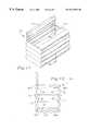
- FIG. 1is an exploded perspective view, with portions in phantom, showing an inflatable insulating shipping box liner receiving a seafood product for shipment, and placed within an outer shipping container in accordance with the present invention
- FIG. 2is a cross-sectional view, taken along line 2 — 2 in FIG. 1, showing an inflatable insulating shipping box liner in accordance with the present invention
- FIG. 3is a partial cross-sectional view taken along line 3 — 3 of FIG. 2, showing the manner in which two panels of an inflatable, insulating shipping box liner are joined together;
- FIG. 4is a top plan view, showing a weld pattern formed on a plastic substrate during the fabrication of an inflatable insulating shipping box liner in accordance with the present invention
- FIGS. 5A-Dare front and side schematic views depicting the manner in which the welded plastic substrate of FIG. 4 is fabricated into an insulating box-like structure;
- FIG. 6is a partial cross-sectional view showing the manner in which a baffle material is received within the inflatable pattern formed in the plastic substrate shown in FIG. 4;
- FIG. 7is a partial top plan view of a baffle material, showing a cut-out pattern corresponding to the weld pattern shown in FIG. 4;
- FIG. 8is an exploded perspective view, with portions in phantom, showing a flexible baffle sheet as received upon a comb-shaped release form in accordance with the present invention
- FIG. 9is an exploded perspective view, with portions in phantom, showing a flexible baffle sheet and comb-shaped release form as received between an inner and an outer film layers in accordance with the present invention
- FIG. 10is a perspective view, with portions in phantom, showing a flexible baffle sheet and comb-shaped release form after attachment of the baffle sheet to the inner and outer film layers in accordance with the present invention
- FIG. 11is a perspective view, with portions in phantom, showing a partially separated pair of inner and outer film layers with a flexible baffle sheet extending in an alternating manner therebetween, with a comb-shaped release form in the process of being removed therefrom in accordance with the present invention
- FIG. 12is a perspective view, with portions in phantom, showing a separated pair of inner and outer film layers with an intermediate flexible baffle, after removal of the comb-shaped release form in accordance with the present invention
- FIG. 13is a top plan view showing a weld pattern in a plastic substrate that defines the inflated portion of an alternative insulating shipping box liner in accordance with the present invention
- FIG. 14is a perspective view showing the alternative inflatable insulating shipping box liner of FIG. 13 in accordance with the present invention.
- FIG. 15is a cross-sectional view, taken along line 15 — 15 in FIG. 14, showing an alternative inflatable insulating shipping box liner in accordance with the present invention
- FIG. 16is a cross-sectional view, taken along line 16 — 16 in FIG. 14, showing the sequence of insulating bladders defining an outer periphery of the inflatable insulating shipping box liner in accordance with the present invention
- FIG. 17is a perspective view showing an alternative inflatable insulating shipping box liner having a honeycomb-baffle container liner in accordance with the present invention.
- FIG. 18is a cross-sectional view, taken along line 18 — 18 in FIG. 17, showing the honeycomb-baffle container liner in accordance with the present invention.
- FIG. 19is a graph comparing temperature changes over time experience by cargo insulated using a liner employing the present invention and a competitive technology.
- FIG. 1An inflatable insulating shipping box liner 10 is depicted in FIG. 1 as received within a transport box bottom 14 .
- a pair of gussets 16 formed at each end of the transport box bottom 14are preferably provided to minimize the likelihood of any liquid leakage from within the transport box bottom 14 .
- a transport box top 18is received by the transport box bottom 14 in a fully telescoping manner, again minimizing the opportunity for the leakage of liquid from the contents carried within the transport box. Additionally, in a conventional manner the transport box bottom and top 14 , 18 are both waxed to preserve their structural integrity against damage caused by liquids that have either leaked from the interior insulating shipping box liner or from liquids wetting an outer surface or surfaces thereof.
- the inflatable insulating shipping box liner 10includes a front wall 22 , a pair of side walls 24 a , 24 b , a rear wall 26 , a floor 28 , and a top or covering flap 32 , which together define an interior container space 34 suitable for the transport of perishable products, such as a fish 36 depicted in FIG. 1 .
- the insulating shipping box liner 10is preferably inflated once placed within the transport box bottom 14 , prior or just after placement of the perishable product within the interior container space 34 .
- Airis introduced into the interior space lying within each of the various structures of the insulating shipping box liner 10 by an inflating valve 38 . All structural portions of the insulating shipping box liner 10 are in fluid communication with one another, permitting air entering through the inflating valve 38 to flow into and inflate all portions of the inflating bag 10 .
- a plurality of different-shaped inflation seams 42govern the manner in which the various component portions of the insulating shipping box liner 10 inflate as well as their resulting configuration.
- the inflation seams 42likewise define a plurality of inflated tubes that are of suitable cross-sectional dimension to provide the structural rigidity required of the various panel members of the insulating shipping box liner 10 .
- the front wall 22consists of an inner material layer 52 and an outer material layer 54 .
- the inflating valve 38or an inert gas such as argon, should greater insulating values be desired
- the inner and outer material layers 52 , 54are separated by the incoming gas, and “balloon out.”
- the inner and outer material layers 52 , 54are joined to one-another, preventing their separation by the incoming charging gas.
- the placement of the inflation seams 42define the shape of the inflated portions of the insulating shipping box liner 10 .
- the latitudinal, spaced-apart inflation seams 42create a vertical arrangement of horizontally-extending inflated tubes.
- Similar arrangements of the inflation seams 42 in the floor 28 , the rear wall 26 , and the top or covering flap 32results in similar inflated horizontal tubular structures that extend the length of the insulating shipping box liner 10 .
- the side walls 24 a , 24 bpresent a variation on this theme, with each consisting of a joined arrangement of three separate lateral panels 58 a , 58 b , 58 c.
- a first and a second of the lateral panels 58 a , 58 bare trapezoidal-shaped extensions of the front and rear walls 22 , 26 .
- a vertically-extending inflation seam 42(shown in FIG. 1) separates the first and second lateral panels 58 a , 58 b from the adjoining portions of the respective front and rear walls 22 , 26 , and forms a side edge when the insulating shipping box liner 10 is inflated.
- the third lateral panel 58 cis formed as a triangularly-shaped extension from the floor 28 , with a linear inflation seam 42 (shown in FIG. 1) also separating these two panels.
- the adjoining lateral edges of the first, second, and third lateral panels 58 a , 58 b , 58 care joined together forming a tri-segment attachment seam 64 (FIGS. 2 and 3 ).
- the lateral panels 58 a , 58 b , 58 ceach present a reduced inflated area, and thus a sequence of spaced longitudinal inflation seams 42 are not required. Instead, a centrally-located “U”-shaped inflation seam 42 is provided each of the lateral panels 58 a , 58 b , 58 c .
- the base of the “U” in each of the panelsis directed toward the angular side of the lateral panel or, in the case of the triangular, third lateral panel 58 c , toward the apex of the triangle.
- the inflation seams 42provide the appropriate restriction for limiting the balloon effect between the inner and the outer material layers 52 , 54 in the lateral panels 58 a , 58 b , 58 c of the inflatable insulating shipping box liner 10 to a specified inflated thickness of, by way of example and not limitation, one inch (1′′).
- the extent or area over which the inner and outer material layers 52 , 54 inflateis defined by a sealing seam 66 that continuously extends about the outer periphery of each of the individual panels making up the inflatable insulating shipping box liner 10 .
- the air or inert gasis admitted through the inflating valve 38 and into the portion of the insulating shipping box liner 10 lying inside of the sealing seam 66 . Once admitted, the sealing seam 66 prevents the gas from escaping, resulting in the inflation of this sealed portion of the insulating shipping box liner 10 .
- a reinforcement seam 68is spaced interiorly from and runs parallel to the sealing seam 66 along the top portion of the inflation bag 10 .
- the reinforcement seam 68acts to stiffen the upper portions of the insulating shipping box liner 10 , as well as to better define the opening of the insulating shipping box liner 10 and thereby assist during the loading and unloading thereof.
- Exterior of the sealing seam 66is located an uninflated flap 72 .
- FIGS. 4 and 5 A-DA presently preferred manner for fabricating the insulated bag 10 is shown in FIGS. 4 and 5 A-D.
- a multi-layer sheetform substrate 82has a multiple seam pattern 84 formed thereon.
- the sheetform substrate 82preferably consists of two layers of a plastic material, and the seam pattern 84 is preferably formed thereon by radio-frequency welding.
- the seam pattern 84comprises both the individual panel construction of the insulating shipping box liner 10 as well as the inflation pattern thereof, as just discussed.
- Each lateral portion of the seam pattern 84defines the lateral panels 58 a , 58 b , 58 c that, when attached together, form the pair of side walls 24 a , 24 b for the insulating shipping box liner 10 .
- the seam pattern 84also defines a series of rectangular sections that, when assembled, form the cover 32 , the front and rear walls 22 , 26 , and the floor 28 . Additionally, although not labeled to maintain drawing clarity, the initial fabrication step also forms the pattern of inflation seams 42 , the sealing seams 66 , and the reinforcement seams 68 .
- a floor-folding seam 88 ais centrally formed in the center of the floor 28 , and is used to assist in the fabrication of the finished bag construction as is hereinafter discussed.
- a pair of parallel, edge-folding seams 88 bare equally spaced-apart on either side of the floor seam 88 a , and form the front and rear bottom edges in the finished insulating shipping box liner 10 .
- a cover-folding seam 88 cis formed at the joinder of the cover 32 and the rear wall 26 , permitting the easy folding of the cover 32 , even after inflation of the insulating shipping box liner 10 .
- FIG. 5Athe front and rear walls 22 , 26 are brought together by first folding on the edge-folding seams 88 b and then collapsing together the floor 28 by oppositely folding on the floor-folding seam 88 a . As properly folded, both resulting halves of the floor 28 are placed between the now-adjoining front and rear walls 22 , 26 (also shown in FIG. 5 B).
- the lateral panels 58engage one another along each of their respective lateral edges (best shown in FIG. 5 C).
- the attachment seams 64may now be formed, again, preferably by radio-frequency welding when plastic sheet substrates are used.
- a release sheet 92is appropriately inserted between the lower half-panels of the floor 28 to prevent the inadvertent attachment of the angled edges of the front and rear wall lateral panels 58 a , 58 b to one another instead of to only the adjoining lateral edges of the floor lateral panel 58 c during this second welding operation.
- the resulting inverted “Y”-shaped attachment seams 64are best shown in FIG. 5C, and illustrate the formation of the side walls 24 a , 24 b out of the three separate lateral panels 58 a , 58 b , 58 c .
- the now-attached separate lateral panels 58expand to form the side walls 24 .
- the resemblance of the insulating shipping box liner 10 to a box-like structureis now apparent, requiring only inflation prior to its use.
- the inner material layer 52is metallized to function as a radiant barrier and the outer material layer 54 is metallized to function as a low emissivity surface, greatly enhancing the insulating qualities of the inflatable insulating shipping box liner 10 in comparison to the insulative effect of inflation alone. Since considerable manufacturing economies are obtained by relying upon radio frequency welding, and with thermal performance significantly improved by metallizing the inner and outer material surfaces 52 , 54 , the materials selected for fabricating these layers must be capable of rf welding and be metallized. It has proven to be somewhat difficult to reconcile these two features.
- the polyolefin filmIn addition to its ability to be RF welded, the polyolefin film also provides good puncture resistance. Unfortunately, polyethylene film does not metallize well, and it does not resist stretching—which potentially permits the overfilling of the inflatable insulating shipping box liner 10 . Polyester film, in addition to being readily metalized, does not stretch yet provides a good burst strength. Together, this laminate forms a firm packaging material, with the inflation thereof through a flat, plastic valve such as those manufactured by Sealed Air Corporation of New Jersey for use in their air-filled packaging systems.
- a presently preferred alternative insulating systeminstead relies upon interior baffles that are provided with a radiational barrier surface.
- FIG. 6a pair of internal baffles 96 are shown received within an adjoining pair of inflated insulated cells 98 of the insulating shipping box liner 10 . These internal baffles 96 are depicted as centered within the insulated cells 98 , which occurs upon inflation as a result of the careful dimensioning of the internal baffles 96 .
- a lateral dimension of the internal baffles 96is selected such that upon the inflation of the insulating cells 98 , the resulting balloon-expansion of the inner and the outer material layers 52 , 54 causes a contraction of the parallel seams adjacent to both sides of the inflation cells 98 , with the internal baffles 96 self-centering in the widest part of the insulating cells 98 .
- a presently preferred technique for placement of the internal baffles 96 within the individual insulating cells 98 formed in the insulating shipping box liner 10is to form the baffle material as a single cut-out that can be received between the inner and outer material layers 52 , 54 at the time of fabricating the insulating shipping box liner 10 .
- FIG. 7such a scheme results in a baffle cut-out sheet 101 having a plurality of inflation seam openings 103 formed therein at locations corresponding to each location in which the inflation seams 42 are formed in the sheetform substrate 82 , as well as a plurality of folding seam openings 105 formed at locations corresponding to the folding seams 88 (compare FIGS. 4 and 7 ).
- Attachment of the top and bottom material layers of the sheetform substrate 82 by RF weldingthereby integrates the inner and outer material layers 52 , 54 with the intermediate baffle cut-out sheet 101 , creating a single, multi-layered material. Subsequently folding and RF welding a second time completes the insulating shipping box liner 10 in the manner previously discussed (see FIGS. 5 A-D).
- the bafflemay be a continuous sheet that is welded in place during the fabrication of the insulating liner.
- the arrangement of its weldsforms a honeycomb-type structured layer out of the continuous sheet, eliminating the requirement that the baffle be die-cut in a manner mimicking the pattern of the subsequently-welded seams.
- Such a baffle materialmust be metallized and rf weldable on both sides, and when attached to alternate interior and exterior liner walls, will kink or separate during inflation of the liner, resulting in a honeycomb structure that further increases the thermal efficiency of the inflatable insulating liner.
- the thermal properties and characteristics of such a honeycomb structureare described in Griffith, et al., U.S. Pat. No. 5,270,092, owned by the Lawrence Berkeley National Laboratory of the University of California.
- FIGS. 8-12A presently preferred method of obtaining such a structure within an insulating liner in accordance with the present invention is depicted in FIGS. 8-12.
- a baffle sheet 107is fabricated out of a material such as polyethylene film, metalized on one side, with that same side then laminated to a second layer of polyethylene film.
- the baffle sheet 107is woven through a comb-shaped release form 109 , with the baffle sheet 107 covering alternating fingers of the release form 109 as is depicted in FIG. 8 .
- the interwoven comb-structureis then placed between the inner material layer 52 and the outer material layer 54 (shown in FIG. 9 ).
- a plurality of spaced weld lines 111are depicted in FIG. 10, with each of the weld lines 111 centrally located over each finger of the release form 109 .
- the baffle sheet 107attaches to the inner material layer 52 by a weld 111 at those locations where it overlies the fingers.
- the baffle sheet 107is woven under the fingers, it is attached by a weld (not shown) to the outer material layer 54 , creating the alternating lines of attachment shown in FIG. 12.
- a final weldis then made to close off the interior portion.
- baffle materialsare feasible, and a further preferred embodiment contemplates the use of a “phase change” material in a baffle, either replacing the kraft paper substrate or as another layer formed therein.
- the kraft paperis replaced by a thermoset polyurethane foam, with a radiant outer barrier formed on its outer surface, such as by the attachment of aluminum foil layers.
- phase change moleculesDispersed within the foam layer are molecules selected to undergo a phase change in the appropriate temperature range. This range can be varied by the manufacturer of the phase change molecules to maximize the performance of thermal protection for various shipping environments. In changing phases, these phase change molecules absorb heat from the environment. By so doing, these molecules significantly reduce the transfer of heat through the baffle material, enhancing the insulating qualities obtained over the radiant barrier alone.
- FIGS. 4 and 5 A- 5 Drequire two separate RF welding operations (“2-Hit Design”).
- 2-Hit Designa single RF weld creates a “1-Hit” insulating shipping box liner 115 (shown in FIG. 14 ).
- the sheetform substrate 82is laid out identically to that previously described, including the insertion of the baffle cut-out sheet 101 (not shown) where this additional insulation is desired.
- the sheetform substrate 82is then folded upon itself, along a fold line 117 .
- a release paper(not shown) having dimensions 1 ⁇ 4′′ less in width than the sheetform substrate is inserted between the folded sheets, and is sufficiently long to extend out therefrom, preventing the top and bottom edges of the substrate from being adhered together during the welding operation that follows.
- an RF welding operation(not depicted in the Figures) is used to form a “1-Hit” seam pattern 119 within the folded sheetform substrate 82 .
- FIG. 13the non-folded outline of such a pattern is shown, which is symmetrical about a linear axis formed by the fold line 117 .
- the “1-Hit” seam pattern 119defines the perimeter of the inflated portion of the “1-Hit” insulating shipping box liner 115 .
- the outer peripheryforms a pair of lateral seams of attachment 120 , which attach the overlying sheetform substrates except at an opposing pair of upper and lower longitudinal edges 121 , 123 .
- the symmetrical folding of the sheetform substrate prior to RF weldingresults in the formation of a pair of front/back sidewall sections 127 a , 127 b .
- the flooris likewise separated by the fold line 117 into a pair of front/back floor sections 131 a , 131 b .
- the front/back sidewall sections 127 a , 127 b and the front/back floor sections 131 a , 131 bcooperate to create an interior fluid containment space upon inflation of the shipping box liner 115 , as is best illustrated by FIG. 14 .
- the seam of attachment 120does not extend along the upper and lower longitudinal edges 121 , 123 , thereby forming a pair of front/back cover sections 135 a , 135 b .
- the location of each of such sections after RF weldingis depicted in FIG. 14 .
- the inflatable portion defined by the “1-Hit” seam pattern 119does not encompass the entire area of the sheetform substrate 82 .
- the uninflated portion adjacent to the front/back floor sections 131 a , 131 bforms a pair of floor gussets 141 (only one shown in FIG. 14 ).
- a pair of partial cover gussets 143are formed adjacent to the front/back cover sections in a similar manner, excepting a non-joined portion that reflects the lack of a seam of attachment along the upper and lower longitudinal edges 121 , 123 .
- the floor gusset 141 and the partial cover gusset 143assist in providing additional sealing protection against liquid leakage from within the “1-Hit” insulating shipping box liner. Additionally, by forming a reservoir to remove from product interface liquids draining from the product, whether as a result of melting ice or natural product exudate, the gusset reservoir enhances product freshness and shelf life.
- the inflation seams and attachment seamshave been omitted from the “1-Hit” design layout shown in FIG. 13 .
- the inflation pattern formed in the “1-Hit” insulating shipping box liner 115is similar, although less complex than with the “2-Hit” insulating shipping box liner 10 of FIG. 1 .
- the 1-Hit insulating shipping box liner 115requires only a latitudinal pattern of inflation seams 42 .
- a series of vertically-arranged, horizontally-extending insulating tubesresults, with each tube extending from and between the pair of lateral seams of attachment 119 (see FIG. 16 ).
- a plurality of corner fold seams 147are formed adjacent to the front/back sidewall sections 127 a , 127 b during the fabrication of the “1-Hit” insulating shipping box liner 115 .
- the corner fold seams 147permit the easy bending of the insulating tubes when transitioning from the front and rear walls 22 , 26 to the side walls 127 .
- honeycomb-baffle container liner 151is shown in FIGS. 17 and 18.
- the front and back cover sections 135 a , 135 bthermally secure the interior containment space of the honeycomb baffle container liner 151 .
- FIG. 18best depicts the manner in which the continuous baffle sheet 107 forms the honeycomb sections as it alternates its seams of attachment between the inner material layer 52 and the outer material layer 54 .
- an inner inflation seam 42 A or an outer inflation seam 42 Bis created.
- a continuous radiant barrieris formed within an inflated envelope, placing the barrier adjacent the air space required for its maximum effectiveness.
- a suitable “2-Hit” inflatable insulating shipping box liner 10would have (when inflated) a floor of measurements 24′′ by 14′′, front and rear walls of height 12′′, and a cover having dimensions of 24′′ by 14′′.
- a suitable thickness (when inflated) for maintaining a desired temperature for 48 hoursis 1′′.
- a “1-Hit” insulating shipping box liner 115would have similar dimensions, except that each of its two covers would have dimensions of 24′′ by 7′′.
- the present invention of dimensions suitable for such a typical shipping boxwould measure 38′′ by 27′′ by 1 ⁇ 2′′ thick, when deflated for shipment. Having cubic dimensions of only 0.30 cubic feet during shipment, the insulating liner of the present invention compares quite favorably to the much more bulky EPS shipping container that would require 2.25 cubic feet for supply shipment and inventory storage.
- the graph of FIG. 19compares internal “product” temperatures over time as occurred between an inflatable insulating shipping box liner placed within an outer corrugated shipping container and an EPS shipping container similarly placed within such a shipping container.
- the ambient temperaturevaries over time as is indicated in FIG. 19 .
Landscapes
- Engineering & Computer Science (AREA)
- Mechanical Engineering (AREA)
- Packages (AREA)
- Buffer Packaging (AREA)
- Filling Or Discharging Of Gas Storage Vessels (AREA)
- Thermal Insulation (AREA)
Abstract
Description
Claims (5)
Priority Applications (10)
| Application Number | Priority Date | Filing Date | Title |
|---|---|---|---|
| US09/156,208US6513974B2 (en) | 1998-09-17 | 1998-09-17 | Inflatable insulating liners for shipping containers |
| EP99951476AEP1129014B1 (en) | 1998-09-17 | 1999-09-17 | Inflatable insulating liners for shipping containers |
| PCT/US1999/021418WO2000015514A1 (en) | 1998-09-17 | 1999-09-17 | Inflatable insulating liners for shipping containers |
| AT99951476TATE326400T1 (en) | 1998-09-17 | 1999-09-17 | INFLATABLE INSULATION LINING FOR SHIPPING CONTAINER |
| DK99951476TDK1129014T3 (en) | 1998-09-17 | 1999-09-17 | Inflatable insulating liners for shipping containers |
| ES99951476TES2268884T3 (en) | 1998-09-17 | 1999-09-17 | INFLATABLE INSULATING COATINGS FOR TRANSPORT CONTAINERS. |
| PT99951476TPT1129014E (en) | 1998-09-17 | 1999-09-17 | INFLATABLE INSULATING LININGS FOR CONTAINERS FOR TRANSPORTATION |
| DE69931387TDE69931387T2 (en) | 1998-09-17 | 1999-09-17 | INFLATABLE INSULATION INSULATION FOR SHIPPING TANK |
| AU63910/99AAU6391099A (en) | 1998-09-17 | 1999-09-17 | Inflatable insulating liners for shipping containers |
| CY20061101152TCY1105312T1 (en) | 1998-09-17 | 2006-08-17 | CONDUCTIVE INSULATION PAPERS FOR SHIPPING BOXES |
Applications Claiming Priority (1)
| Application Number | Priority Date | Filing Date | Title |
|---|---|---|---|
| US09/156,208US6513974B2 (en) | 1998-09-17 | 1998-09-17 | Inflatable insulating liners for shipping containers |
Related Child Applications (1)
| Application Number | Title | Priority Date | Filing Date |
|---|---|---|---|
| US10/248,641Continuation-In-PartUS20030128898A1 (en) | 1999-09-17 | 2003-02-03 | Inflatable insulating liners including phase change material |
Publications (2)
| Publication Number | Publication Date |
|---|---|
| US20020064318A1 US20020064318A1 (en) | 2002-05-30 |
| US6513974B2true US6513974B2 (en) | 2003-02-04 |
Family
ID=22558577
Family Applications (1)
| Application Number | Title | Priority Date | Filing Date |
|---|---|---|---|
| US09/156,208Expired - LifetimeUS6513974B2 (en) | 1998-09-17 | 1998-09-17 | Inflatable insulating liners for shipping containers |
Country Status (10)
| Country | Link |
|---|---|
| US (1) | US6513974B2 (en) |
| EP (1) | EP1129014B1 (en) |
| AT (1) | ATE326400T1 (en) |
| AU (1) | AU6391099A (en) |
| CY (1) | CY1105312T1 (en) |
| DE (1) | DE69931387T2 (en) |
| DK (1) | DK1129014T3 (en) |
| ES (1) | ES2268884T3 (en) |
| PT (1) | PT1129014E (en) |
| WO (1) | WO2000015514A1 (en) |
Cited By (36)
| Publication number | Priority date | Publication date | Assignee | Title |
|---|---|---|---|---|
| US20010015178A1 (en)* | 1998-08-12 | 2001-08-23 | Rose Seafood Industries, Inc. | Container for storage and/or shipment of live crustaceans |
| US20020004724A1 (en)* | 2000-07-05 | 2002-01-10 | Eastman Winthrop A. | Method for shipping temperature-sensitive goods |
| US20030128898A1 (en)* | 1999-09-17 | 2003-07-10 | Malone Thomas G. | Inflatable insulating liners including phase change material |
| US20040056038A1 (en)* | 2002-09-05 | 2004-03-25 | Hardy Paul N. | Deployable bag for a vacuum box |
| US20040069789A1 (en)* | 2002-09-12 | 2004-04-15 | Takashi Ohno | Heat-insulating container |
| US20040161175A1 (en)* | 2000-12-21 | 2004-08-19 | Cargo Technology, Inc. | Inflatable insulating liners for shipping containers |
| US20040163991A1 (en)* | 2002-05-28 | 2004-08-26 | Yoshihiro Koyanagi | Cubic cushioning material and production method thereof |
| US20060101789A1 (en)* | 2004-11-18 | 2006-05-18 | Yasuzumi Tanaka | Multi-purpose air-packing method and system |
| US20060257600A1 (en)* | 2005-05-12 | 2006-11-16 | Pilaar James G | Inflatable sound attenuation system |
| US20060261579A1 (en)* | 2004-04-02 | 2006-11-23 | Automotive Technologies International, Inc. | Airbags with Internal Valves |
| US20080118680A1 (en)* | 2006-11-17 | 2008-05-22 | Yao Sin Liao | Air enclosure with independent double layer air chambers |
| US20080196304A1 (en)* | 2007-02-15 | 2008-08-21 | Bethel Farms Ltd. | Protective cover for vegetative material and associated methods |
| US20080260303A1 (en)* | 2007-04-23 | 2008-10-23 | Coldkeepers, Llc | Insulsted shipping bags |
| US20080308448A1 (en)* | 2006-01-05 | 2008-12-18 | Paige Chemene Allen | Inflatable Food Carrier Case |
| US20100032335A1 (en)* | 2006-10-18 | 2010-02-11 | Swisspal Ag | Packaging Device |
| US20100062921A1 (en)* | 2008-09-11 | 2010-03-11 | Simple Container Solutions, Inc. | Expandable insulated packaging |
| US20110127189A1 (en)* | 2008-01-04 | 2011-06-02 | Liao, Chieh Hua | Bendable multi-sectional cushioning cover bag |
| US20110226657A1 (en)* | 2008-03-31 | 2011-09-22 | Jiaying Zhang | Air packaging device product and method for forming the product |
| US20120000807A1 (en)* | 2009-03-13 | 2012-01-05 | Elizabeth Scarbrough | Inflatable, reusable and leak-resistant carrier |
| US20120243808A1 (en)* | 2007-04-23 | 2012-09-27 | Coldkeepers, Llc | Insulated liners and containers |
| US20120291335A1 (en)* | 2011-05-19 | 2012-11-22 | Brooke Thomas C | Fish Livewell and Padding System Therefor |
| US20130089279A1 (en)* | 2011-10-11 | 2013-04-11 | Yaw Shin Liao | Airbag structure with inner shade cover and manufacturing method thereof |
| US20130270145A1 (en)* | 2012-03-15 | 2013-10-17 | Toshiko TAKENAKA | Packing material and packing method |
| US20140328551A1 (en)* | 2011-12-12 | 2014-11-06 | Bag Pack (B.P.) Ltd. | Inflated package, precursor and method |
| US20160060017A1 (en)* | 2007-04-23 | 2016-03-03 | Coldkeepers, Llc | Insulated shipping bags |
| US20160374441A1 (en)* | 2013-07-18 | 2016-12-29 | Anyvention Ltd. | An expandable bag and a method for the expanding of bags |
| US20170119116A1 (en)* | 2015-03-11 | 2017-05-04 | Swell Industries Llc | Drop-stitch inflatable cooler |
| US9744752B2 (en) | 2012-01-24 | 2017-08-29 | Inflatek Innovations, Llc | Inflatable panel and method of manufacturing same |
| US10093450B2 (en) | 2016-11-07 | 2018-10-09 | Dell Products, L.P. | Transportation pallet and method for depalletizing load |
| US10167128B2 (en) | 2013-06-12 | 2019-01-01 | Airguard Ltd. | Inflator device and method for inflatable packaging |
| USD843677S1 (en)* | 2017-08-23 | 2019-03-19 | Helmut Elze | Load securement system |
| US10322843B2 (en) | 2016-12-01 | 2019-06-18 | Drew Foam Companies Inc. | Collapsible insulating container liner |
| US20210309444A1 (en)* | 2020-04-01 | 2021-10-07 | Qingwen Yang | Thermally insulated three-dimensional bag |
| US11155396B2 (en)* | 2016-06-08 | 2021-10-26 | Airguard Ltd. | Multipurpose inflatable package |
| US11608221B2 (en) | 2018-06-15 | 2023-03-21 | Cold Chain Technologies, Llc | Shipping system for storing and/or transporting temperature-sensitive materials |
| US11634266B2 (en) | 2019-01-17 | 2023-04-25 | Cold Chain Technologies, Llc | Thermally insulated shipping system for parcel-sized payload |
Families Citing this family (46)
| Publication number | Priority date | Publication date | Assignee | Title |
|---|---|---|---|---|
| US20040188302A1 (en)* | 2003-03-26 | 2004-09-30 | Rogers Julian R. | Packaging device and method |
| GB0502206D0 (en)* | 2005-02-03 | 2005-03-09 | Tattam Edwin F | Transport container |
| US7445117B2 (en)* | 2005-09-19 | 2008-11-04 | Air-Paq, Inc. | Structure of air-packing device |
| GB2439065B (en)* | 2006-06-14 | 2008-10-15 | Hwan Yih Entpr Co Ltd | Packaging pad structure |
| TW200827253A (en)* | 2006-12-29 | 2008-07-01 | Chieh-Hua Liao | Block reinforced air enclosure and manufacture thereof |
| NL1033580C2 (en)* | 2007-03-23 | 2008-09-24 | Heijden Nederland V D | Gas supply device for space between pair of films, e.g. for air cushion in packaging, comprises tube with lateral hole and sealed with flanged plate for inserting into openings in films |
| GB2451329A (en)* | 2007-07-24 | 2009-01-28 | Paul Harrison | Insulating liner |
| TW200930632A (en)* | 2008-01-04 | 2009-07-16 | Chieh-Hua Liao | Foldable multi-section buffer packaging bag |
| US8210346B2 (en)* | 2009-03-23 | 2012-07-03 | Raytheon Company | Light weight and collapsible weapons container |
| KR20120100882A (en)* | 2009-06-21 | 2012-09-12 | 존 토마스 리들 | Collapsible bottle, method of manufacturing a blank for such bottle and beverage-filled bottle dispensing system |
| US20130129261A1 (en)* | 2010-07-13 | 2013-05-23 | Samdel Corporation Limited | Insulating Material |
| KR200461825Y1 (en) | 2011-04-25 | 2012-08-20 | 조세환 | Portable coolant container |
| CN103407693B (en)* | 2013-08-28 | 2016-03-23 | 陆晶晶 | Packing box |
| GB201321311D0 (en)* | 2013-12-03 | 2014-01-15 | Jf Hillebrand Ltd | A Protective liner for use in the shipping of articles |
| US20150201755A1 (en)* | 2014-01-21 | 2015-07-23 | The Norix Group | Partially Ballasted Shelving Unit |
| WO2016187435A2 (en) | 2015-05-20 | 2016-11-24 | Temperpak Technologies Inc. | Thermal insulation liners |
| NL2016022B1 (en)* | 2015-12-23 | 2017-07-05 | Horeman Jelle | Packaging. |
| GB201602505D0 (en)* | 2016-02-12 | 2016-03-30 | Ocado Innovation Ltd | Storage systems,methods and containers |
| CN205906475U (en)* | 2016-07-15 | 2017-01-25 | 浙江大自然旅游用品有限公司 | Aerify insulation can |
| US10583977B2 (en) | 2016-08-16 | 2020-03-10 | Mp Global Products, L.L.C. | Method of making an insulation material and an insulated mailer |
| MY206209A (en) | 2017-02-16 | 2024-12-04 | Vericool Inc | Compostable insulation for shipping container |
| US10442600B2 (en) | 2017-04-07 | 2019-10-15 | Pratt Retail Specialties, Llc | Insulated bag |
| US10800595B2 (en) | 2017-04-07 | 2020-10-13 | Pratt Retail Specialties, Llc | Box liner |
| US10954057B2 (en) | 2017-05-09 | 2021-03-23 | Pratt Retail Specialties, Llc | Insulated box |
| US10604304B2 (en) | 2017-05-09 | 2020-03-31 | Pratt Retail Specialties, Llc | Insulated bag with handles |
| US10551110B2 (en) | 2017-07-31 | 2020-02-04 | Pratt Retail Specialties, Llc | Modular box assembly |
| EP3462797A1 (en) | 2017-09-28 | 2019-04-03 | Panasonic Intellectual Property Corporation of America | User equipment and base station participating in prioritized random access |
| US10507968B2 (en) | 2017-12-18 | 2019-12-17 | Pratt Retail Specialties, Llc | Modular box assembly |
| US10947025B2 (en) | 2017-12-18 | 2021-03-16 | Pratt Corrugated Holdings, Inc. | Insulated block packaging assembly |
| US11059652B2 (en)* | 2018-05-24 | 2021-07-13 | Pratt Corrugated Holdings, Inc. | Liner |
| US11097887B2 (en)* | 2018-06-13 | 2021-08-24 | California Innovations Inc. | Insulated container with folding closure |
| CN112585066B (en)* | 2018-07-04 | 2022-09-13 | 库尔全球解决方案有限公司 | Thermally insulated container |
| US10858141B2 (en) | 2018-11-13 | 2020-12-08 | Pratt Retail Specialties, Llc | Insulated box assembly with overlapping panels |
| US11066228B2 (en) | 2018-11-13 | 2021-07-20 | Pratt Retail Specialties, Llc | Insulated box assembly and temperature-regulating lid therefor |
| EP3718924A1 (en)* | 2019-04-03 | 2020-10-07 | Storopack Hans Reichenecker GmbH | Container system |
| US11027875B2 (en) | 2019-05-02 | 2021-06-08 | Pratt Retail Specialties, Llc | Telescoping insulated boxes |
| US10882684B2 (en) | 2019-05-02 | 2021-01-05 | Pratt Retail Specialties, Llc | Box defining walls with insulation cavities |
| CN110116852A (en)* | 2019-06-05 | 2019-08-13 | 东莞市银滨实业有限公司 | A kind of splicing box type aeration buffering box structure |
| US11230404B2 (en) | 2019-11-26 | 2022-01-25 | Pratt Corrugated Holdings, Inc. | Perforated collapsible box |
| US11718464B2 (en) | 2020-05-05 | 2023-08-08 | Pratt Retail Specialties, Llc | Hinged wrap insulated container |
| USD968950S1 (en) | 2020-08-10 | 2022-11-08 | Pratt Corrugated Holdings, Inc. | Perforated collapsible box |
| US12270153B2 (en) | 2021-02-11 | 2025-04-08 | Pratt Corrugated Holdings, Inc. | Starch-cellulose composite material |
| JP2022139142A (en)* | 2021-03-11 | 2022-09-26 | コニカミノルタ株式会社 | Transportation box |
| US12168562B2 (en)* | 2023-01-31 | 2024-12-17 | Abel1950 Inc. | Container for cooling food and method for construction |
| US20240365941A1 (en)* | 2023-05-02 | 2024-11-07 | Rosemarie Castellanos | Reusable, reconfigurable, and inflatable tote shipper and packaging system |
| CN118850558B (en)* | 2024-09-24 | 2024-12-17 | 泉州玛塔生态科技有限公司 | Oyster shell treatment equipment and process thereof |
Citations (30)
| Publication number | Priority date | Publication date | Assignee | Title |
|---|---|---|---|---|
| US3556186A (en)* | 1968-10-18 | 1971-01-19 | Gerard Besthorne | Inflatable bag |
| US3730240A (en)* | 1971-03-16 | 1973-05-01 | Metatronics Manuf Corp | Inflatable insulation for packaging |
| DE2339078A1 (en)* | 1973-08-02 | 1975-02-13 | Eckhard Dr Hundhausen | Heat insulating frozen food carrier bag - has an inflatable double outer skin with internal reflective layer |
| DE2549179A1 (en)* | 1975-11-03 | 1977-06-23 | Sterr Herbert | Inflatable bathing bag - unfolds and inflates to form sunshade |
| US4044867A (en)* | 1976-06-03 | 1977-08-30 | Fisher Robert J | Inflatable luggage |
| FR2367671A1 (en)* | 1976-10-16 | 1978-05-12 | Rolz Anna Eleonore | Frozen prods. insulated carrier bag - has inflatable quilted walls and has net stretched between walls to hold products |
| US4091852A (en)* | 1977-04-11 | 1978-05-30 | Jordan Charles P | Inflatable box |
| DE2750819A1 (en) | 1977-11-14 | 1979-05-17 | Hubert Prof Dipl Phys Hermkes | Thermal insulation for protective wear, heating or cooling plant - is plastics laminate enclosing air-filled cavities with heat-reflecting metallised walls |
| US4262045A (en) | 1979-03-16 | 1981-04-14 | Cheng Chen Yen | Cellular air bag insulation and insulator |
| US4284674A (en) | 1979-11-08 | 1981-08-18 | American Can Company | Thermal insulation |
| US4618517A (en) | 1984-06-29 | 1986-10-21 | Simko Jr Frank A | Thermal insulating material |
| US4636416A (en) | 1984-05-18 | 1987-01-13 | Wacker-Chemie Gmbh | Shaped microporous thermal insulation body with sheathing and process for making same |
| US4669632A (en) | 1984-12-04 | 1987-06-02 | Nippon Sanso Kabushiki Kaisha | Evacuated heat insulation unit |
| US4801213A (en)* | 1987-10-19 | 1989-01-31 | Airelle Industries, Inc. | Inflatable insert for luggage |
| US4809352A (en)* | 1987-11-27 | 1989-02-28 | Walker Kyle B | Inflatable cooler |
| US4826329A (en)* | 1987-03-18 | 1989-05-02 | Ing. C. Olivetti & C., S.P.A. | Flexible bag, in particular for office machines |
| US5180060A (en)* | 1991-07-10 | 1993-01-19 | Jarvis Chemicals & Paper Company | Inflatable, encapsulating packaging insert |
| US5217131A (en)* | 1992-07-08 | 1993-06-08 | Andrews Catherine M L | Shipping container apparatus |
| US5263587A (en)* | 1992-08-31 | 1993-11-23 | Plastic Development, Inc. | Inflatable packaging pouch |
| US5270092A (en) | 1991-08-08 | 1993-12-14 | The Regents, University Of California | Gas filled panel insulation |
| US5314250A (en)* | 1993-05-18 | 1994-05-24 | Lee Ung L | Inflatable container |
| US5427830A (en)* | 1992-10-14 | 1995-06-27 | Air Packaging Technologies, Inc. | Continuous, inflatable plastic wrapping material |
| US5454642A (en) | 1993-07-16 | 1995-10-03 | Novus Packaging Corporation | Inflatable flat bag packaging cushion and methods of operating and making the same |
| US5588532A (en) | 1994-09-15 | 1996-12-31 | Air Packaging Technologies, Inc. | Self-sealing inflatable bag and method for packaging an article therein |
| US5706969A (en) | 1995-03-27 | 1998-01-13 | Nippon Sanso Corporation | Insulated container, insulating material, and manufacturing method of the insulated container |
| US5769232A (en)* | 1996-08-16 | 1998-06-23 | Cash; Ronnie L. | Inflatable protective lining sysem for containers |
| US5820268A (en)* | 1996-07-30 | 1998-10-13 | Jotan, Inc. | Insulated container for packaging perishable goods |
| US5857571A (en)* | 1997-12-01 | 1999-01-12 | Tschantz; Mitchell | Inflatable packaging cushion |
| US6176613B1 (en)* | 2000-05-04 | 2001-01-23 | Tzan-Kuo Chen | Packing bag with air cushion |
| US6283296B1 (en)* | 1998-12-29 | 2001-09-04 | Air Packaging Technologies, Inc. | Quilted inflatable packaging device |
Family Cites Families (2)
| Publication number | Priority date | Publication date | Assignee | Title |
|---|---|---|---|---|
| CH687456A5 (en)* | 1994-01-05 | 1996-12-13 | Urs Siegrist | Padding insert for Transportbehaelter. |
| US5535888A (en)* | 1994-11-23 | 1996-07-16 | Novus Packaging Corporation | Thermal insulating and cushioning package and method of making the same |
- 1998
- 1998-09-17USUS09/156,208patent/US6513974B2/ennot_activeExpired - Lifetime
- 1999
- 1999-09-17PTPT99951476Tpatent/PT1129014E/enunknown
- 1999-09-17EPEP99951476Apatent/EP1129014B1/ennot_activeExpired - Lifetime
- 1999-09-17AUAU63910/99Apatent/AU6391099A/ennot_activeAbandoned
- 1999-09-17WOPCT/US1999/021418patent/WO2000015514A1/enactiveSearch and Examination
- 1999-09-17ATAT99951476Tpatent/ATE326400T1/ennot_activeIP Right Cessation
- 1999-09-17DKDK99951476Tpatent/DK1129014T3/enactive
- 1999-09-17ESES99951476Tpatent/ES2268884T3/ennot_activeExpired - Lifetime
- 1999-09-17DEDE69931387Tpatent/DE69931387T2/ennot_activeExpired - Lifetime
- 2006
- 2006-08-17CYCY20061101152Tpatent/CY1105312T1/enunknown
Patent Citations (30)
| Publication number | Priority date | Publication date | Assignee | Title |
|---|---|---|---|---|
| US3556186A (en)* | 1968-10-18 | 1971-01-19 | Gerard Besthorne | Inflatable bag |
| US3730240A (en)* | 1971-03-16 | 1973-05-01 | Metatronics Manuf Corp | Inflatable insulation for packaging |
| DE2339078A1 (en)* | 1973-08-02 | 1975-02-13 | Eckhard Dr Hundhausen | Heat insulating frozen food carrier bag - has an inflatable double outer skin with internal reflective layer |
| DE2549179A1 (en)* | 1975-11-03 | 1977-06-23 | Sterr Herbert | Inflatable bathing bag - unfolds and inflates to form sunshade |
| US4044867A (en)* | 1976-06-03 | 1977-08-30 | Fisher Robert J | Inflatable luggage |
| FR2367671A1 (en)* | 1976-10-16 | 1978-05-12 | Rolz Anna Eleonore | Frozen prods. insulated carrier bag - has inflatable quilted walls and has net stretched between walls to hold products |
| US4091852A (en)* | 1977-04-11 | 1978-05-30 | Jordan Charles P | Inflatable box |
| DE2750819A1 (en) | 1977-11-14 | 1979-05-17 | Hubert Prof Dipl Phys Hermkes | Thermal insulation for protective wear, heating or cooling plant - is plastics laminate enclosing air-filled cavities with heat-reflecting metallised walls |
| US4262045A (en) | 1979-03-16 | 1981-04-14 | Cheng Chen Yen | Cellular air bag insulation and insulator |
| US4284674A (en) | 1979-11-08 | 1981-08-18 | American Can Company | Thermal insulation |
| US4636416A (en) | 1984-05-18 | 1987-01-13 | Wacker-Chemie Gmbh | Shaped microporous thermal insulation body with sheathing and process for making same |
| US4618517A (en) | 1984-06-29 | 1986-10-21 | Simko Jr Frank A | Thermal insulating material |
| US4669632A (en) | 1984-12-04 | 1987-06-02 | Nippon Sanso Kabushiki Kaisha | Evacuated heat insulation unit |
| US4826329A (en)* | 1987-03-18 | 1989-05-02 | Ing. C. Olivetti & C., S.P.A. | Flexible bag, in particular for office machines |
| US4801213A (en)* | 1987-10-19 | 1989-01-31 | Airelle Industries, Inc. | Inflatable insert for luggage |
| US4809352A (en)* | 1987-11-27 | 1989-02-28 | Walker Kyle B | Inflatable cooler |
| US5180060A (en)* | 1991-07-10 | 1993-01-19 | Jarvis Chemicals & Paper Company | Inflatable, encapsulating packaging insert |
| US5270092A (en) | 1991-08-08 | 1993-12-14 | The Regents, University Of California | Gas filled panel insulation |
| US5217131A (en)* | 1992-07-08 | 1993-06-08 | Andrews Catherine M L | Shipping container apparatus |
| US5263587A (en)* | 1992-08-31 | 1993-11-23 | Plastic Development, Inc. | Inflatable packaging pouch |
| US5427830A (en)* | 1992-10-14 | 1995-06-27 | Air Packaging Technologies, Inc. | Continuous, inflatable plastic wrapping material |
| US5314250A (en)* | 1993-05-18 | 1994-05-24 | Lee Ung L | Inflatable container |
| US5454642A (en) | 1993-07-16 | 1995-10-03 | Novus Packaging Corporation | Inflatable flat bag packaging cushion and methods of operating and making the same |
| US5588532A (en) | 1994-09-15 | 1996-12-31 | Air Packaging Technologies, Inc. | Self-sealing inflatable bag and method for packaging an article therein |
| US5706969A (en) | 1995-03-27 | 1998-01-13 | Nippon Sanso Corporation | Insulated container, insulating material, and manufacturing method of the insulated container |
| US5820268A (en)* | 1996-07-30 | 1998-10-13 | Jotan, Inc. | Insulated container for packaging perishable goods |
| US5769232A (en)* | 1996-08-16 | 1998-06-23 | Cash; Ronnie L. | Inflatable protective lining sysem for containers |
| US5857571A (en)* | 1997-12-01 | 1999-01-12 | Tschantz; Mitchell | Inflatable packaging cushion |
| US6283296B1 (en)* | 1998-12-29 | 2001-09-04 | Air Packaging Technologies, Inc. | Quilted inflatable packaging device |
| US6176613B1 (en)* | 2000-05-04 | 2001-01-23 | Tzan-Kuo Chen | Packing bag with air cushion |
Cited By (61)
| Publication number | Priority date | Publication date | Assignee | Title |
|---|---|---|---|---|
| US20010015178A1 (en)* | 1998-08-12 | 2001-08-23 | Rose Seafood Industries, Inc. | Container for storage and/or shipment of live crustaceans |
| US20030128898A1 (en)* | 1999-09-17 | 2003-07-10 | Malone Thomas G. | Inflatable insulating liners including phase change material |
| US20020004724A1 (en)* | 2000-07-05 | 2002-01-10 | Eastman Winthrop A. | Method for shipping temperature-sensitive goods |
| US20040161175A1 (en)* | 2000-12-21 | 2004-08-19 | Cargo Technology, Inc. | Inflatable insulating liners for shipping containers |
| US7066331B2 (en)* | 2002-05-28 | 2006-06-27 | Kabushiki Kaisha Kashiwara Seitai | Cubic cushioning material and production method thereof |
| US20040163991A1 (en)* | 2002-05-28 | 2004-08-26 | Yoshihiro Koyanagi | Cubic cushioning material and production method thereof |
| US6988632B2 (en)* | 2002-09-05 | 2006-01-24 | Hardy Paul N | Deployable bag for a vacuum box |
| US20040056038A1 (en)* | 2002-09-05 | 2004-03-25 | Hardy Paul N. | Deployable bag for a vacuum box |
| US20040069789A1 (en)* | 2002-09-12 | 2004-04-15 | Takashi Ohno | Heat-insulating container |
| US7338069B2 (en) | 2004-04-02 | 2008-03-04 | Automotive Technologies International, Inc. | Airbags with internal valves |
| US20060261579A1 (en)* | 2004-04-02 | 2006-11-23 | Automotive Technologies International, Inc. | Airbags with Internal Valves |
| US20060101789A1 (en)* | 2004-11-18 | 2006-05-18 | Yasuzumi Tanaka | Multi-purpose air-packing method and system |
| US20060278554A1 (en)* | 2004-11-18 | 2006-12-14 | Yasuzumi Tanaka | Multi-purpose air-packing method and system |
| US7254932B2 (en)* | 2004-11-18 | 2007-08-14 | Air-Paq, Inc. | Multi-purpose air-packing method and system |
| US20060257600A1 (en)* | 2005-05-12 | 2006-11-16 | Pilaar James G | Inflatable sound attenuation system |
| US7992678B2 (en)* | 2005-05-12 | 2011-08-09 | Pilaar James G | Inflatable sound attenuation system |
| US8469144B2 (en) | 2005-05-12 | 2013-06-25 | James G. Pilaar | Inflatable sound attenuation system |
| US20080308448A1 (en)* | 2006-01-05 | 2008-12-18 | Paige Chemene Allen | Inflatable Food Carrier Case |
| US20100032335A1 (en)* | 2006-10-18 | 2010-02-11 | Swisspal Ag | Packaging Device |
| US20080118680A1 (en)* | 2006-11-17 | 2008-05-22 | Yao Sin Liao | Air enclosure with independent double layer air chambers |
| US8088459B2 (en)* | 2006-11-17 | 2012-01-03 | Yao Sin Liao | Air enclosure with independent double layer air chambers |
| US20080196304A1 (en)* | 2007-02-15 | 2008-08-21 | Bethel Farms Ltd. | Protective cover for vegetative material and associated methods |
| WO2008100395A1 (en)* | 2007-02-15 | 2008-08-21 | Bethel Farms Ltd. | Protective cover for vegetative material and associated methods |
| US9980609B2 (en)* | 2007-04-23 | 2018-05-29 | Coldkeepers, Llc | Insulated shipping bags |
| US20160198901A1 (en)* | 2007-04-23 | 2016-07-14 | Coldkeepers, Llc | Insulated shipping bags |
| US20080260303A1 (en)* | 2007-04-23 | 2008-10-23 | Coldkeepers, Llc | Insulsted shipping bags |
| US20120243808A1 (en)* | 2007-04-23 | 2012-09-27 | Coldkeepers, Llc | Insulated liners and containers |
| US9950830B2 (en)* | 2007-04-23 | 2018-04-24 | Coldkeepers, Llc | Insulated liners and containers |
| US20180237182A1 (en)* | 2007-04-23 | 2018-08-23 | Coldkeepers, Llc | Insulated liners and containers |
| US20160060017A1 (en)* | 2007-04-23 | 2016-03-03 | Coldkeepers, Llc | Insulated shipping bags |
| US9650198B2 (en)* | 2007-04-23 | 2017-05-16 | Coldkeepers, Llc | Insulated shipping bags |
| US10457440B2 (en)* | 2007-04-23 | 2019-10-29 | Coldkeepers, Llc | Insulated liners and containers |
| US9290313B2 (en)* | 2007-04-23 | 2016-03-22 | Coldkeepers, Llc | Insulated shipping bags |
| US10913570B2 (en) | 2007-04-23 | 2021-02-09 | Coldkeepers, Llc | Insulated liners and containers |
| US20110127189A1 (en)* | 2008-01-04 | 2011-06-02 | Liao, Chieh Hua | Bendable multi-sectional cushioning cover bag |
| US8366594B2 (en)* | 2008-03-31 | 2013-02-05 | Jiaying Zhang | Air packaging device product and method for forming the product |
| US20110226657A1 (en)* | 2008-03-31 | 2011-09-22 | Jiaying Zhang | Air packaging device product and method for forming the product |
| US8333279B2 (en) | 2008-09-11 | 2012-12-18 | Simple Container Solutions, Inc. | Expandable insulated packaging |
| US20100062921A1 (en)* | 2008-09-11 | 2010-03-11 | Simple Container Solutions, Inc. | Expandable insulated packaging |
| US20120000807A1 (en)* | 2009-03-13 | 2012-01-05 | Elizabeth Scarbrough | Inflatable, reusable and leak-resistant carrier |
| US20120291335A1 (en)* | 2011-05-19 | 2012-11-22 | Brooke Thomas C | Fish Livewell and Padding System Therefor |
| US8770840B2 (en)* | 2011-10-11 | 2014-07-08 | Yaw Shin Liao | Airbag structure with inner shade cover and manufacturing method thereof |
| US20130089279A1 (en)* | 2011-10-11 | 2013-04-11 | Yaw Shin Liao | Airbag structure with inner shade cover and manufacturing method thereof |
| US11066225B2 (en) | 2011-12-12 | 2021-07-20 | Airguard Ltd. | Inflated package, precursor and method |
| US20140328551A1 (en)* | 2011-12-12 | 2014-11-06 | Bag Pack (B.P.) Ltd. | Inflated package, precursor and method |
| US10040618B2 (en)* | 2011-12-12 | 2018-08-07 | Airguard Ltd. | Inflated package, precursor and method |
| US9744752B2 (en) | 2012-01-24 | 2017-08-29 | Inflatek Innovations, Llc | Inflatable panel and method of manufacturing same |
| US20130270145A1 (en)* | 2012-03-15 | 2013-10-17 | Toshiko TAKENAKA | Packing material and packing method |
| US8960437B2 (en)* | 2012-03-15 | 2015-02-24 | Toshiko TAKENAKA | Gas storing packing material and packing method |
| US11084642B2 (en) | 2013-06-12 | 2021-08-10 | Airguard Ltd. | Inflator device and method for inflatable packaging |
| US10167128B2 (en) | 2013-06-12 | 2019-01-01 | Airguard Ltd. | Inflator device and method for inflatable packaging |
| US20160374441A1 (en)* | 2013-07-18 | 2016-12-29 | Anyvention Ltd. | An expandable bag and a method for the expanding of bags |
| US20170119116A1 (en)* | 2015-03-11 | 2017-05-04 | Swell Industries Llc | Drop-stitch inflatable cooler |
| US10799002B2 (en)* | 2015-03-11 | 2020-10-13 | Swell Industries Llc | Drop-stitch inflatable cooler |
| US11155396B2 (en)* | 2016-06-08 | 2021-10-26 | Airguard Ltd. | Multipurpose inflatable package |
| US10093450B2 (en) | 2016-11-07 | 2018-10-09 | Dell Products, L.P. | Transportation pallet and method for depalletizing load |
| US10322843B2 (en) | 2016-12-01 | 2019-06-18 | Drew Foam Companies Inc. | Collapsible insulating container liner |
| USD843677S1 (en)* | 2017-08-23 | 2019-03-19 | Helmut Elze | Load securement system |
| US11608221B2 (en) | 2018-06-15 | 2023-03-21 | Cold Chain Technologies, Llc | Shipping system for storing and/or transporting temperature-sensitive materials |
| US11634266B2 (en) | 2019-01-17 | 2023-04-25 | Cold Chain Technologies, Llc | Thermally insulated shipping system for parcel-sized payload |
| US20210309444A1 (en)* | 2020-04-01 | 2021-10-07 | Qingwen Yang | Thermally insulated three-dimensional bag |
Also Published As
| Publication number | Publication date |
|---|---|
| EP1129014A1 (en) | 2001-09-05 |
| EP1129014A4 (en) | 2003-06-04 |
| DE69931387T2 (en) | 2007-02-01 |
| WO2000015514A1 (en) | 2000-03-23 |
| ATE326400T1 (en) | 2006-06-15 |
| CY1105312T1 (en) | 2010-03-03 |
| EP1129014B1 (en) | 2006-05-17 |
| WO2000015514A9 (en) | 2000-08-17 |
| DK1129014T3 (en) | 2006-09-18 |
| AU6391099A (en) | 2000-04-03 |
| US20020064318A1 (en) | 2002-05-30 |
| PT1129014E (en) | 2006-09-29 |
| DE69931387D1 (en) | 2006-06-22 |
| ES2268884T3 (en) | 2007-03-16 |
Similar Documents
| Publication | Publication Date | Title |
|---|---|---|
| US6513974B2 (en) | Inflatable insulating liners for shipping containers | |
| US20030128898A1 (en) | Inflatable insulating liners including phase change material | |
| ES2283454T3 (en) | INFLATABLE INSULATING COATING FOR TRANSPORT PACKINGS, AND METHOD FOR MANUFACTURING IT. | |
| EP2657141B1 (en) | Insulated shipping bags | |
| US20090314786A1 (en) | Insulated water-tight container | |
| US5445274A (en) | Inflatable package insert | |
| US3889743A (en) | Inflatable insulation for packaging | |
| US6296134B1 (en) | Insulated water-tight container | |
| US5535888A (en) | Thermal insulating and cushioning package and method of making the same | |
| US20160060017A1 (en) | Insulated shipping bags | |
| US6431361B1 (en) | Container paneling for forming pneumatically padded boxes and padded box construction | |
| AU6806900A (en) | Dual chamber flexible container | |
| US20030047564A1 (en) | Insulated container and methods for making and storing the same | |
| CN212922730U (en) | Anticollision heat preservation packing box | |
| CN212244567U (en) | But reuse's gas column bag for cold chain | |
| CN111824595A (en) | But reuse's gas column bag for cold chain | |
| HK1056155B (en) | Inflatable insulating liner for shipping containers and method of manufacturing thereof |
Legal Events
| Date | Code | Title | Description |
|---|---|---|---|
| AS | Assignment | Owner name:IMPERIAL BANK, CALIFORNIA Free format text:SECURITY AGREEMENT;ASSIGNOR:CARGO TECHNOLOGY, INC.;REEL/FRAME:011749/0433 Effective date:20010315 | |
| AS | Assignment | Owner name:E*CAPITAL CORPORATION, CALIFORNIA Free format text:SECURITY AGREEMENT;ASSIGNOR:CARGO TECHNOLOGY, INC.;REEL/FRAME:014128/0554 Effective date:20030403 Owner name:FARMERS AND MERCHANTS TRUST COMPANY, CALIFORNIA Free format text:SECURITY AGREEMENT;ASSIGNOR:CARGO TECHNOLOGY, INC.;REEL/FRAME:014128/0554 Effective date:20030403 Owner name:HAMILTON APEX TECHNOLOGY VENTURES, L.P., CALIFORNI Free format text:SECURITY AGREEMENT;ASSIGNOR:CARGO TECHNOLOGY, INC.;REEL/FRAME:014128/0554 Effective date:20030403 Owner name:UNITED PARCEL SERVICE GENERAL SERVICES CO., GEORGI Free format text:SECURITY AGREEMENT;ASSIGNOR:CARGO TECHNOLOGY, INC.;REEL/FRAME:014128/0554 Effective date:20030403 | |
| AS | Assignment | Owner name:CARGO TECHNOLOGY, INC., CALIFORNIA Free format text:REASSIGNMENT AND RELEASE OF SECURITY INTEREST.;ASSIGNOR:COMERCIA BANK, SUCCESSOR IN INTEREST TO IMPERIAL BANK;REEL/FRAME:014705/0859 Effective date:20031114 | |
| AS | Assignment | Owner name:CARGO TECHNOLOGY INC, CALIFORNIA Free format text:ASSIGNMENT OF ASSIGNORS INTEREST;ASSIGNOR:MALONE, THOMAS G;REEL/FRAME:014141/0060 Effective date:20031118 | |
| AS | Assignment | Owner name:CARGO TECHNOLOGY, INC, CALIFORNIA Free format text:ASSIGNMENT OF ASSIGNORS INTEREST;ASSIGNOR:MCGRAW, JOHN J;REEL/FRAME:014143/0862 Effective date:20031120 | |
| FPAY | Fee payment | Year of fee payment:4 | |
| AS | Assignment | Owner name:COLD PACK SYSTEM, S.A.S., FRANCE Free format text:ASSIGNMENT OF ASSIGNORS INTEREST;ASSIGNOR:CARGO TECHNOLOGY, INC.;REEL/FRAME:021316/0299 Effective date:20070606 | |
| AS | Assignment | Owner name:COLD PACK SYSTEM S.A., FRANCE Free format text:CHANGE OF NAME;ASSIGNOR:COLD PACK SYSTEM, S.A.S.;REEL/FRAME:021936/0597 Effective date:20061220 Owner name:COLD PACK S.A., FRANCE Free format text:CHANGE OF NAME;ASSIGNOR:COLD PACK SYSTEM S.A.;REEL/FRAME:021936/0533 Effective date:20070629 Owner name:COLD PACK INC., CALIFORNIA Free format text:LICENSE;ASSIGNOR:COLD PACK S.A.;REEL/FRAME:021936/0542 Effective date:20080115 | |
| AS | Assignment | Owner name:COLDPACK, FRANCE Free format text:CHANGE OF NAME;ASSIGNOR:COLD PACK;REEL/FRAME:023228/0560 Effective date:20080806 | |
| FEPP | Fee payment procedure | Free format text:PAYER NUMBER DE-ASSIGNED (ORIGINAL EVENT CODE: RMPN); ENTITY STATUS OF PATENT OWNER: SMALL ENTITY Free format text:PAYOR NUMBER ASSIGNED (ORIGINAL EVENT CODE: ASPN); ENTITY STATUS OF PATENT OWNER: SMALL ENTITY | |
| FPAY | Fee payment | Year of fee payment:8 | |
| REMI | Maintenance fee reminder mailed | ||
| LAPS | Lapse for failure to pay maintenance fees | ||
| REIN | Reinstatement after maintenance fee payment confirmed | ||
| FP | Lapsed due to failure to pay maintenance fee | Effective date:20150204 | |
| FEPP | Fee payment procedure | Free format text:PETITION RELATED TO MAINTENANCE FEES GRANTED (ORIGINAL EVENT CODE: PMFG); ENTITY STATUS OF PATENT OWNER: SMALL ENTITY Free format text:PETITION RELATED TO MAINTENANCE FEES FILED (ORIGINAL EVENT CODE: PMFP); ENTITY STATUS OF PATENT OWNER: SMALL ENTITY | |
| FPAY | Fee payment | Year of fee payment:12 | |
| PRDP | Patent reinstated due to the acceptance of a late maintenance fee | Effective date:20160524 | |
| SULP | Surcharge for late payment | ||
| STCF | Information on status: patent grant | Free format text:PATENTED CASE |