US6512994B1 - Method and apparatus for producing a three-dimensional digital model of an orthodontic patient - Google Patents
Method and apparatus for producing a three-dimensional digital model of an orthodontic patientDownload PDFInfo
- Publication number
- US6512994B1 US6512994B1US09/560,641US56064100AUS6512994B1US 6512994 B1US6512994 B1US 6512994B1US 56064100 AUS56064100 AUS 56064100AUS 6512994 B1US6512994 B1US 6512994B1
- Authority
- US
- United States
- Prior art keywords
- video data
- scaled
- orthodontic
- scaling
- tooth
- Prior art date
- Legal status (The legal status is an assumption and is not a legal conclusion. Google has not performed a legal analysis and makes no representation as to the accuracy of the status listed.)
- Expired - Lifetime
Links
Images


Classifications
- A—HUMAN NECESSITIES
- A61—MEDICAL OR VETERINARY SCIENCE; HYGIENE
- A61C—DENTISTRY; APPARATUS OR METHODS FOR ORAL OR DENTAL HYGIENE
- A61C7/00—Orthodontics, i.e. obtaining or maintaining the desired position of teeth, e.g. by straightening, evening, regulating, separating, or by correcting malocclusions
- A61C7/12—Brackets; Arch wires; Combinations thereof; Accessories therefor
- A61C7/14—Brackets; Fixing brackets to teeth
- A61C7/146—Positioning or placement of brackets; Tools therefor
- A—HUMAN NECESSITIES
- A61—MEDICAL OR VETERINARY SCIENCE; HYGIENE
- A61C—DENTISTRY; APPARATUS OR METHODS FOR ORAL OR DENTAL HYGIENE
- A61C7/00—Orthodontics, i.e. obtaining or maintaining the desired position of teeth, e.g. by straightening, evening, regulating, separating, or by correcting malocclusions
- A61C7/002—Orthodontic computer assisted systems
- A—HUMAN NECESSITIES
- A61—MEDICAL OR VETERINARY SCIENCE; HYGIENE
- A61F—FILTERS IMPLANTABLE INTO BLOOD VESSELS; PROSTHESES; DEVICES PROVIDING PATENCY TO, OR PREVENTING COLLAPSING OF, TUBULAR STRUCTURES OF THE BODY, e.g. STENTS; ORTHOPAEDIC, NURSING OR CONTRACEPTIVE DEVICES; FOMENTATION; TREATMENT OR PROTECTION OF EYES OR EARS; BANDAGES, DRESSINGS OR ABSORBENT PADS; FIRST-AID KITS
- A61F2/00—Filters implantable into blood vessels; Prostheses, i.e. artificial substitutes or replacements for parts of the body; Appliances for connecting them with the body; Devices providing patency to, or preventing collapsing of, tubular structures of the body, e.g. stents
- A61F2/02—Prostheses implantable into the body
- A61F2/30—Joints
- A61F2/3094—Designing or manufacturing processes
- A61F2/30942—Designing or manufacturing processes for designing or making customized prostheses, e.g. using templates, CT or NMR scans, finite-element analysis or CAD-CAM techniques
- A61F2002/30953—Designing or manufacturing processes for designing or making customized prostheses, e.g. using templates, CT or NMR scans, finite-element analysis or CAD-CAM techniques using a remote computer network, e.g. Internet
Definitions
- This inventionrelates generally to the practice of orthodontics and in particular to a method and apparatus for treating an orthodontic patient.
- Orthodonticsis the practice of manipulating a patient's teeth to provide better function and appearance.
- bracketsare bonded to a patient's teeth and coupled together with an arched wire. The combination of the brackets and wire provide a force on the teeth causing them to move.
- the bodyadapts bone and tissue to maintain the teeth in the desired location.
- a patientmay be fitted with a retainer.
- orthodontistsutilize their expertise to first determine a three-dimensional mental image of the patient's physical orthodontic structure and a three-dimensional mental image of a desired physical orthodontic structure for the patient, which may be assisted through the use of x-rays and/or models. Based on these mental images, the orthodontist further relies on his/her expertise to place the brackets and/or bands on the teeth and to manually bend (i.e., shape) wire, such that a force is asserted on the teeth ,to reposition the teeth into the desired physical orthodontic structure.
- the orthodontistmakes continual judgments as to the progress of the treatment, the next step in the treatment (e.g., new bend in the wire, reposition or replace brackets, is head gear required, etc.), and the success of the previous step.
- the next step in the treatmente.g., new bend in the wire, reposition or replace brackets, is head gear required, etc.
- the orthodontistmakes manual adjustments to the wire and/or replaces or repositions brackets based on his or her expert opinion.
- a humanin the oral environment, it is impossible for a human being to accurately develop a visual three-dimensional image of an orthodontic structure due to the limitations of human sight and the physical structure of a human mouth.
- orthodontic treatmentis an iterative process requiring multiple wire changes, with the process success and speed being very much dependent on the orthodontist's motor skills and diagnostic expertise.
- process success and speedbeing very much dependent on the orthodontist's motor skills and diagnostic expertise.
- patient discomfortis increased as well as the cost.
- quality of carevaries greatly from orthodontist to orthodontist as does the time to treat a patient.
- U.S. Pat. No. 5,518,397 issued to Andreiko, et. al.provides a method of forming an orthodontic brace. Such a method includes obtaining a model of the teeth of a patient's mouth and a prescription of desired positioning of such teeth. The contour of the teeth of the patient's mouth is determined, from the model. Calculations of the contour and the desired positioning of the patient's teeth are then made to determine the geometry (e.g., grooves or slots) to be provided.
- the geometrye.g., grooves or slots
- Custom brackets including a special geometryare then created for receiving an arch wire to form an orthodontic brace system.
- Such geometryis intended to provide for the disposition of the arched wire on the bracket in a progressive curvature in a horizontal plane and a substantially linear configuration in a vertical plane.
- the geometry of the bracketsis altered, (e.g., by cutting grooves into the brackets at individual positions and angles and with particular depth) in accordance with such calculations of the bracket geometry.
- the bracketsare customized to provide three-dimensional movement of the teeth, once the wire, which has a two dimensional shape (i.e., linear shape in the vertical plane and curvature in the horizontal plane), is applied to the brackets.
- each bracketis the focal point for orthodontic manipulation.
- placement of each bracket on a corresponding toothis critical. Since each bracket includes a custom sized and positioned wire retaining groove, a misplacement of a bracket by a small amount (e.g., an error vector having a magnitude of millimeter or less and an angle of a few degrees or less) can cause a different force system (i.e., magnitude of movement and direction of movement) than the desired force system to be applied to the tooth. As such, the tooth will not be repositioned to the desired location.
- bracketsbeing the focal point
- the orthodontistuses his or her expertise to make the appropriate changes.
- the treatmentmay not progress as originally calculated for several reasons. For example, misplacement of a bracket, misapplication of a bend in the wire, loss or attrition of a bracket, bonding failure, the patient falls outside of the “normal” patient model (e.g., poor growth, anatomical constraints, etc.), patient lack of cooperation in use of auxiliary appliance, etc. are factors in delayed treatment results.
- bracketsare expensive.
- a customized bracketis produced by milling a piece of metal (e.g., stainless steel, aluminum, ceramic, titanium, etc.) and tumble polishing the milled bracket. While the milling process is very accurate, some of the accuracy is lost by tumble polishing. Further accuracy is lost in that the placement of the brackets on the teeth and installation of the wire are imprecise operations. As is known, a slight misplacement of one bracket changes the force on multiple teeth and hinders treatment. To assist in the placement of the custom brackets, they are usually shipped to the orthodontist in an installation jig. Such an installation jig is also expensive. Thus, such scientific orthodontic treatment is expensive and has many inherent inaccuracies.
- FIGS. 1A-1Eillustrate a graphical diagram of orthodontic data in accordance with the present invention
- FIG. 2illustrates a graphical diagram of scaling in accordance with the present invention
- FIG. 3illustrates a graphical diagram of an alternate scaling approach in accordance with the present invention
- FIG. 4illustrates a graphical diagram of x-rayed teeth in accordance with the present invention
- FIG. 5illustrates a graphical diagram of scaling the x-rayed tooth in accordance with the present invention
- FIGS. 6A-6Cillustrate a graphical representation of determining orientation reference points in accordance with the present invention
- FIGS. 7 and 8illustrate a graphical representation of mapping the orientation reference points to a three-dimensional coordinate system in accordance with the present invention.
- FIG. 9illustrates a logic diagram of a method for producing a three-dimensional digital model of an orthodontic patient in accordance with the present invention.
- the present inventionprovides a method and apparatus for producing a three-dimensional digital model of an orthodontic patient.
- a method and apparatusinclude processing that begins by obtaining data of an orthodontic structure of the orthodontic patient. The processing then continues by obtaining at least one scaling reference point of the orthodontic structure.
- the scaling reference pointmay be a marking placed on a tooth prior to obtaining the data.
- the processingcontinues by scaling the data of the orthodontic structure based on the at least one scaling reference point to produce scaled data.
- the datamay be video data, x-rays, CAT scans, ultrasound, and/or magnetic resonance images.
- the processthen continues by obtaining at least two orientation reference points relating to the orthodontic structure (i.e., fixed physical attributes of the orthodontic structure that will not change, or will change with negligible effects, during the course of treatment).
- the processingthen continues by mapping the scaled data to a coordinate system based on the at least two orientation reference points to produce an enhanced three-dimensional digital model of the orthodontic patient.
- the automated treatment of an orthodontic patientoccurs in a scientific and controlled manner.
- patient treatmentcan be simulated by a computer in three-dimensional space, thereby providing a scientific approach to orthodontic treatment.
- FIGS. 1A-1Eillustrate various views of a graphical representation of orthodontic data 10 of the orthodontic structure of an orthodontic patient.
- the orthodontic datais scan data representing a three-dimensional graphic surface image of the patient's teeth, gums, lips, and other surfaces of the facial area.
- the orthodontic data shown in FIGS. 1A-1Eonly includes the teeth 12 and gums 14 .
- the surfacesmay also include lips, cheeks, chin, nose, etc.
- the orthodontic datamay be obtained by scanning a patient's mouth to obtain video data thereof.
- the scanningmay be done utilizing a laser scanner, light scanner, ultrasound, MRI, CAT scan, or other scanning technique, such as the scanning technique, such as the scanning technique disclosed in patent application Ser. No. 09/560,584, filed on Apr. 28, 2000, which is hereby incorporated herein by reference.
- the light scanner approachmay be directly performed on the patient while a laser scanner and other scanning techniques are typically done on a plaster model. Regardless of the scanning technique, three-dimensional images of the surface of the orthodontic structure are obtained.
- FIG. 2illustrates a graphical representation of scaling the orthodontic data to match the actual orthodontic size.
- the orthodontic datawill not completely reproduce the exact size of the teeth and other portions of the orthodontic structure.
- at least one tooth 22can be marked utilizing markings 24 . The marking is done prior to obtaining the orthodontic data.
- the scaling reference points 26are also obtained. A determination between the differences between the scaling reference points 26 and the actual markings 24 determine a scaling factor 28 .
- a variety of mathematical operationsmay be used to determine the scaling factor.
- the differences in area formed by the trianglesmay be used to generate the scaling factor
- the coordinate differences between each of the vertices of the trianglemay be utilized.
- a different number of markings 24may be utilized. For example, two markings may be used or four markings may be used, etc.
- more than one toothmay be marked with similar markings 24 . Note that the markings may be on the exterior of the patient, and a local triangulation technique may be used to obtain the scaling factor.
- scaling factor 28 determinationis based on an assumption that the video data 10 will have a linear error term in each of the x, y and z axis, such that a single scaling factor is determined and used to scale each of the teeth as well as the other aspects of the orthodontic structure of the patient. Such scaling will be discussed with reference to FIGS. 4-9.
- FIG. 3illustrates an alternate marking technique for determining a scaling factor for the orthodontic data.
- an actual tooth 32is marked with a marking 34 .
- the marking 34is of a substantial size to be adequately measured.
- the orthodontic data of the tooth 30 and a corresponding scaling reference point 36are used to determine the scaling factor 38 .
- a simple mathematical functionmay be used to determine the scaling factor 38 based on the size difference between the actual marking 34 and the scaling reference point 36 .
- the actual tooth sizemay be measured and used to determine the scaling factor. Accordingly, the difference between the actual tooth size the size of the tooth in the video data 10 will constitute the scaling factor.
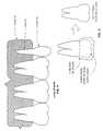
- FIG. 4illustrates a two-dimensional representation of image data, such as a graphical diagram of a radiographic image, such as an x-ray of a few teeth.
- the radiographic imagecan be a computed tomographic image volume.
- the orthodontic datacontains three-dimensional images of the surface of the orthodontic structure. X-rays provide a more detailed view of the teeth and surrounding hard and soft tissue as two dimensional image data. As shown in FIG. 4, each tooth includes a crown 44 and a root 42 and is embedded in bone 40 . Accordingly, the orthodontic data only illustrates the crown 44 of the teeth. As such, the three-dimensional model of the orthodontic patient requires the roots and bone to be included.
- the X-ray imagecan include addition facial and/or cranial features other than those illustrated or described.
- FIG. 5illustrates a graphical representation of using the scaled digital model 48 of the tooth's crown to produce an integrated or composite digital model 50 of the tooth.
- the x-rayed data 46 of the toothis used in comparison with the scaled digital model to determine a per tooth scaling factor.
- the scaled digital model 48 of the toothis positioned to be planar with the x-ray of the tooth 46 . Having obtained the proper orientation between the two objects, the per tooth scaling factor is determined and subsequently used to generate the composite scaled digital model 50 of the tooth.
- the per tooth scaling factoris required for current x-ray technologies, since x-rays produce a varying amount of distortion from tooth to tooth depending on the distance of the tooth from the film, the angle of x-ray transmission, etc.
- a side, a front, and a bottom view of the toothshould be taken and mapped to the scaled digital model of the tooth.
- the bone and other portions of the orthodontic structureare scaled in a similar manner.
- MRI images, and any other images obtained of the orthodontic patientmay also be scaled in a similar manner.
- FIGS. 6A-6Cillustrate a graphical diagram of selecting orientation reference points based on physical attributes of the orthodontic structure.
- the orientation reference points 62 and 66will be subsequently used to map the digital image of the orthodontic structure into a three-dimensional coordinate system that will not change during the course of treatment.
- the frenum 64has been selected to be one of the orientation reference points 66 and the rugae 60 has been selected as the other reference point 62 .
- the frenum 64is a fixed point in the orthodontic patient that will not change, or change minimally, during the course of treatment.
- the frenumis a triangular shaped tissue in the upper-portion of the gum of the upper-arch.
- the rugae 60is a cavity in the roof of the mouth 68 in the upper-arch.
- the rugaewill also not change its physical position through treatment.
- the frenum 64 and the rugae 60are fixed physical points in the orthodontic patient that will not change during treatment.
- a three-dimensional coordinate systemmay be mapped thereto.
- other physical attributes of the orthodontic patientmay be used as the orientation reference points 62 and 66 .
- such physical pointsneed to remain constant throughout treatment.
- alternate physical pointsinclude the incisive papilla, cupid's bow, the inter-pupillar midpoint, inter-comissural midpoint (e.g., between the lips), inter-alar midpoint (e.g., between the sides of the nose), the prone nasale (e.g., the tip of the nose), sub-nasale (e.g., junction of the nose and the lip), a dental mid-line point, a point on the bone, a fixed bone marker such as an implant (e.g., a screw from a root canal, oral surgery).
- an implante.g., a screw from a root canal, oral surgery.
- the x, y, z coordinate systemmay be mapped to the physical points on the digital module of the orthodontic structure in a variety of ways.
- the origin of the x, y, z coordinate systemmay be placed at the frenum 64 , the z-axis aligned with reference to the frenum and the rugae 60 , and the x-axis is aligned with the midline of the upper and/or lower arch. This is further illustrated in FIGS. 7 and 8.
- an external positioning systemmay be used to obtain the orientation reference points.
- the patientmay sit in a chair at a specific location of an examination room that includes a triangulation positioning system therein. As such, when the patient is scanned, the scanned images may be referenced with respect to the room's triangulation positioning system.
- FIG. 7illustrates a graphical representation of mapping the orientation reference points 62 and 66 to the x-z plane of the three-dimensional x, y, z coordinate system.
- orientation point 66which corresponds to the frenum 64 , is selected as the origin of the x, y, z coordinate system. Note that any location may be selected as the origin 72 .
- the orientation points 62 and 66are used to determine an x, z plane orientation angle 62 .
- the x, y, z coordinate systemwill be selected such that when looking at the patient from a frontal view, the x direction will be to right of the patient, the y direction towards the top of the patient's head and the z direction will be out away from the patient.
- the orientation of the x, y, z planemay be in any orientation with respect to the reference points 62 and 66 .
- the x-y planeis mapped to the orientation reference point 62 and 66 as shown in FIG. 8 .
- the orientation reference point 62 and 66are used to generate an x-y plane orientation angle 84 .
- a digital model of a tooth 70may be positioned in three-dimensional space with respect to the x, y, z coordinate system. As shown in FIGS.
- the digital model of the tooth 70includes a tooth depth 78 , an angle of rotation 76 with respect to the x-z axis, an angle of rotation 82 with respect to the x-y plane, a positioning vector 74 which is in a three-dimensional space, the length of the tooth including the crown dimension, and the root dimension. Accordingly, each tooth is then mapped into the x, y, z coordinate system based on the tooth's center, or any other point of the tooth, and the dimensions of the digital model of the corresponding tooth. Once each tooth has been placed into the x, y, z coordinate system, the digital model of the tooth is complete.
- the lower-archis also referenced to the x, y, z coordinate system wherein the determination is made based on the occlusal plane of the patient's orthodontic structure.
- the lower-archmay include a separate three-dimensional coordinate system that is mapped to the coordinate system of the upper-arch. In this latter example, fixed points within the lower-arch would need to be determined to produce the lower arches three-dimensional coordinate system.
- FIG. 9illustrates a logic diagram of a method for producing a three-dimensional digital model of an orthodontic patient.
- the processing steps of FIG. 9may be implemented as operational instructions that are stored in memory and executed by a processing module.
- the processing module and memorymay be of the type found in the orthodontic server as described in co-pending patent application, which is hereby incorporated by reference, having Ser. No. 09/560,643, entitled METHOD AND APPARATUS FOR DETERMINING AND MONITORING ORTHODONTIC TREATMENT, a filing date the same as the present application, and is assigned to the same assignee as the present patent application.
- the processbegins at step 90 where orthodontic data of an orthodontic structure of an orthodontic patient is obtained.
- the orthodontic dataincludes a three-dimensional graphical surface image of the orthodontic structure, which may be obtained as video data using a light scanner, laser scanner, ultra sound scanner, and/or other scanning device.
- the orthodontic datamay further include two dimensional data such as x-rays, MRIs, CAT scans, photographs, etc.
- the systemmay obtain color information of the teeth and surrounding soft tissue to use as texture information for the three-dimensional object.
- the three-dimensional surface image which may be obtained as video dataincludes information regarding the teeth surface, gum surface, lips surface and facial surface.
- the video datamay be dynamic motion of the orthodontic structure which will be later used to determine appropriate functionality of the orthodontic structure.
- step 92at least one scaling reference point of the orthodontic structure is obtained. This may be done by marking at least two points on one or more teeth via a jig, marking a tooth with a known shape via a jig, measuring at least two anatomical points, identifying at least two points on a true three-dimensional model, and/or measuring physical dimensions of a tooth.
- the processthen proceeds to step 94 where the data is scaled based on the at least one scaling reference.
- the surface datawhich may be obtained as video data, is scaled first.
- x-rays and/or photographsmay be scaled in accordance with the scaled video data.
- the scalingmust be done on a tooth by tooth basis by orientating the scaled video data on a tooth by tooth basis such that the digital module of the tooth surface is substantially planer with the two-dimensional x-ray, MRI, etc. of a given tooth. Having done this, a scaling factor is determined for the given tooth based on the planer scaled video data and the two-dimensional image.
- the two-dimensional imagery of the toothi.e., root and crown
- the two-dimensional imagery of the toothis then scaled based on the scaling factor to produce a scaled tooth. This was illustrated with respect to FIG. 5 . Note that regardless of whether the data contains scanned images that were obtained via an MRI process, infrared process, CAT scan, ultrasound, and/or laser scan, such images are scaled in accordance with the scaled video data.
- a three-dimensional modelcan be reduced by changing the virtual orientation of the three-dimensional model to match the two dimensional view.
- the scalingis done by manipulating the three dimensional model. Additional fine tuning of the three-dimensional model orientation can be subsequently performed to achieve a best fit.
- any dentition points that can be clearly recognized and defined in both the three-dimensional image and the two-dimensional imagee.g. incisor edges, cusps, etc. can be used to align the images.
- step 96at least two orientation reference points that relate to the orthodontic structure are obtained.
- These reference pointsmay be applied by a practitioner, or local care provider, and may include the mid-point frenum, incisive papilla, rugae, cupid's bow, inter-pupillar midpoint, inter-comissural midpoint, inter-alar midpoint, prone nasale, sub-nasale, dental mid-line point, a fixed point on a bone, a fixed bone marker such as implants that resulted from a root canal, oral surgery, etc.
- facial featuresmay be used as the reference points, which include the ear, lateral aspect of the face, the bottom of the chin, the nose, etc.
- step 98the scaled data is mapped to a coordinate system based on the at least two reference points.
- the orthodontic dataincludes a motion picture of the orthodontic structure
- the moving lower archis mapped to the coordinate system to obtain functional accuracy of the orthodontic structure.
- the movement of the jaw, and hence the orthodontic structurecan be determined by including the bone portions related to the jaw using the techniques described herein. This allows a simulation using the integrated simulation model to determine alignment and position of the lower jaw. Therefore, modifications to the location of dentition structures in a digital model can be simulated using movement of the jaw to determine if the planned location of the dentition structures is appropriate, or if additional modification of the model will create a better result.
- step 100at least one stress point of the orthodontic structure is highlighted.
- the stress pointcould be within the jaw, mouth or anywhere in the head and is determined based on contact between at least one upper-tooth and lower-tooth of the orthodontic structure.
- the stress pointis subsequently used to determine a desired orthodontic structure as discussed in co-pending patent application, which is hereby incorporated by reference, having Ser. No. 09/560,134, entitled METHOD AND APPARATUS FOR GENERATING A DESIRED THREE-DIMENSIONAL DIGITAL MODEL OF AN IDEAL ORTHODONTIC STRUCTURE, having a filing date the same as the present patent application, and is assigned to the same assignee as the present patent application.
- any factor that effects tooth movementi.e. brackets, wires, adhesion, physiological changes
- any factor that effects tooth movementcan be simulated to determine appropriate treatment changes.
- Such compensation in treatmentis not possible using prior methods which were based upon assumptions from a single model that the tooth movement would progress in a known manner. Therefore, the prior art methods would specify and a single static treatment based upon this assumption. If any unwanted tooth movement occurred during treatment, the specified treatment would no longer be valid, requiring changes to be made based upon a practitioner's expertise.
- the present systemprovides a dynamic system that through the use of periodic feedback, i.e. periodic three-dimensional scanning, can be monitored and adjusted as needed by the system in an efficient manner.
- periodic feedbacki.e. periodic three-dimensional scanning
- unexpected tooth movementsuch as occurs when a patient does not cooperate, or through biological changes, can be readily
Landscapes
- Health & Medical Sciences (AREA)
- Oral & Maxillofacial Surgery (AREA)
- Dentistry (AREA)
- Epidemiology (AREA)
- Life Sciences & Earth Sciences (AREA)
- Animal Behavior & Ethology (AREA)
- General Health & Medical Sciences (AREA)
- Public Health (AREA)
- Veterinary Medicine (AREA)
- Dental Tools And Instruments Or Auxiliary Dental Instruments (AREA)
Abstract
Description
Claims (27)
Priority Applications (20)
| Application Number | Priority Date | Filing Date | Title |
|---|---|---|---|
| US09/560,641US6512994B1 (en) | 1999-11-30 | 2000-04-28 | Method and apparatus for producing a three-dimensional digital model of an orthodontic patient |
| EP10004337.1AEP2204136B1 (en) | 2000-04-19 | 2001-04-13 | Orthodontic archwire |
| PCT/US2001/011969WO2001080761A2 (en) | 2000-04-19 | 2001-04-13 | Interactive orthodontic care system based on intra-oral scanning of teeth |
| AT01928490TATE488313T1 (en) | 2000-04-19 | 2001-04-13 | BENDING MACHINE FOR A MEDICAL DEVICE |
| US09/834,593US7068825B2 (en) | 1999-03-08 | 2001-04-13 | Scanning system and calibration method for capturing precise three-dimensional information of objects |
| EP10009822.7AEP2258303B1 (en) | 2000-04-19 | 2001-04-13 | System for creating an individual three-dimensional virtual tooth model |
| JP2001577864AJP2004504077A (en) | 2000-04-19 | 2001-04-13 | Interactive orthodontic care system based on intraoral scanning of teeth |
| US09/835,039US6648640B2 (en) | 1999-11-30 | 2001-04-13 | Interactive orthodontic care system based on intra-oral scanning of teeth |
| EP01928490.0AEP1301140B2 (en) | 2000-04-19 | 2001-04-13 | Bending machine for a medical device |
| US10/280,758US7029275B2 (en) | 1999-11-30 | 2002-10-24 | Interactive orthodontic care system based on intra-oral scanning of teeth |
| US10/340,404US20030105611A1 (en) | 1999-11-30 | 2003-01-09 | Method and apparatus for producing a three-dimensional digital model of an orthodontic patient |
| US10/429,123US7234937B2 (en) | 1999-11-30 | 2003-05-02 | Unified workstation for virtual craniofacial diagnosis, treatment planning and therapeutics |
| US10/951,119US7013191B2 (en) | 1999-11-30 | 2004-09-27 | Interactive orthodontic care system based on intra-oral scanning of teeth |
| US10/993,323US7058213B2 (en) | 1999-03-08 | 2004-11-18 | Scanning system and calibration method for capturing precise three-dimensional information of objects |
| US11/285,629US7590462B2 (en) | 1999-11-30 | 2005-11-22 | Interactive orthodontic care system based on intra-oral scanning of teeth |
| US11/387,387US7305110B2 (en) | 1999-03-08 | 2006-03-23 | Scanning system and calibration method for capturing precise three-dimensional information of objects |
| US11/799,390US8113829B2 (en) | 1999-11-30 | 2007-05-01 | Unified workstation for virtual craniofacial diagnosis, treatment planning and therapeutics |
| JP2007261981AJP5269380B2 (en) | 2000-04-19 | 2007-10-05 | Interactive orthodontic care system based on intraoral scanning of teeth |
| US12/510,921US8121718B2 (en) | 1999-11-30 | 2009-07-28 | Interactive orthodontic care system based on intra-oral scanning of teeth |
| JP2012090832AJP2012179370A (en) | 2000-04-19 | 2012-04-12 | Interactive orthodontic care system based on intra-oral scanning of teeth |
Applications Claiming Priority (2)
| Application Number | Priority Date | Filing Date | Title |
|---|---|---|---|
| US45203499A | 1999-11-30 | 1999-11-30 | |
| US09/560,641US6512994B1 (en) | 1999-11-30 | 2000-04-28 | Method and apparatus for producing a three-dimensional digital model of an orthodontic patient |
Related Parent Applications (5)
| Application Number | Title | Priority Date | Filing Date |
|---|---|---|---|
| US45203499AContinuation-In-Part | 1999-03-08 | 1999-11-30 | |
| US56064000AContinuation-In-Part | 1999-11-30 | 2000-04-28 | |
| US09/560,584Continuation-In-PartUS7068836B1 (en) | 1999-03-08 | 2000-04-28 | System and method for mapping a surface |
| US09/560,134Continuation-In-PartUS6851949B1 (en) | 1999-03-08 | 2000-04-28 | Method and apparatus for generating a desired three-dimensional digital model of an orthodontic structure |
| US11/799,390Continuation-In-PartUS8113829B2 (en) | 1999-11-30 | 2007-05-01 | Unified workstation for virtual craniofacial diagnosis, treatment planning and therapeutics |
Related Child Applications (8)
| Application Number | Title | Priority Date | Filing Date |
|---|---|---|---|
| US09/560,133Continuation-In-PartUS6744932B1 (en) | 1999-03-08 | 2000-04-28 | System and method for mapping a surface |
| US09/560,642Continuation-In-PartUS6688885B1 (en) | 1999-11-30 | 2000-04-28 | Method and apparatus for treating an orthodontic patient |
| US09/834,593Continuation-In-PartUS7068825B2 (en) | 1999-03-08 | 2001-04-13 | Scanning system and calibration method for capturing precise three-dimensional information of objects |
| US09/835,039Continuation-In-PartUS6648640B2 (en) | 1999-11-30 | 2001-04-13 | Interactive orthodontic care system based on intra-oral scanning of teeth |
| US09/835,039ContinuationUS6648640B2 (en) | 1999-11-30 | 2001-04-13 | Interactive orthodontic care system based on intra-oral scanning of teeth |
| US10/280,758Continuation-In-PartUS7029275B2 (en) | 1999-11-30 | 2002-10-24 | Interactive orthodontic care system based on intra-oral scanning of teeth |
| US10/340,404ContinuationUS20030105611A1 (en) | 1999-11-30 | 2003-01-09 | Method and apparatus for producing a three-dimensional digital model of an orthodontic patient |
| US10/993,323Continuation-In-PartUS7058213B2 (en) | 1999-03-08 | 2004-11-18 | Scanning system and calibration method for capturing precise three-dimensional information of objects |
Publications (1)
| Publication Number | Publication Date |
|---|---|
| US6512994B1true US6512994B1 (en) | 2003-01-28 |
Family
ID=27036622
Family Applications (2)
| Application Number | Title | Priority Date | Filing Date |
|---|---|---|---|
| US09/560,641Expired - LifetimeUS6512994B1 (en) | 1999-03-08 | 2000-04-28 | Method and apparatus for producing a three-dimensional digital model of an orthodontic patient |
| US10/340,404AbandonedUS20030105611A1 (en) | 1999-11-30 | 2003-01-09 | Method and apparatus for producing a three-dimensional digital model of an orthodontic patient |
Family Applications After (1)
| Application Number | Title | Priority Date | Filing Date |
|---|---|---|---|
| US10/340,404AbandonedUS20030105611A1 (en) | 1999-11-30 | 2003-01-09 | Method and apparatus for producing a three-dimensional digital model of an orthodontic patient |
Country Status (1)
| Country | Link |
|---|---|
| US (2) | US6512994B1 (en) |
Cited By (60)
| Publication number | Priority date | Publication date | Assignee | Title |
|---|---|---|---|---|
| US20020006217A1 (en)* | 2000-04-28 | 2002-01-17 | Orametrix, Inc. | Methods for registration of three-dimensional frames to create three-dimensional virtual models of objects |
| US20020055800A1 (en)* | 2000-02-17 | 2002-05-09 | Sergey Nikolskiy | Efficient data representation of teeth model |
| US20030012423A1 (en)* | 2001-06-28 | 2003-01-16 | Eastman Kodak Company | Method and system for creating dental models from imagery |
| US20030021453A1 (en)* | 2000-04-28 | 2003-01-30 | Thomas Weise | Method and apparatus for registering a known digital object to scanned 3-D model |
| US20040002873A1 (en)* | 1999-11-30 | 2004-01-01 | Orametrix, Inc. | Method and apparatus for automated generation of a patient treatment plan |
| US20040015327A1 (en)* | 1999-11-30 | 2004-01-22 | Orametrix, Inc. | Unified workstation for virtual craniofacial diagnosis, treatment planning and therapeutics |
| US20040029068A1 (en)* | 2001-04-13 | 2004-02-12 | Orametrix, Inc. | Method and system for integrated orthodontic treatment planning using unified workstation |
| US6694212B1 (en)* | 2002-03-27 | 2004-02-17 | James P. Kennedy | Computer-aided design of a pontic with retainers |
| US20040122306A1 (en)* | 2002-12-20 | 2004-06-24 | Eastman Kodak Company | Intra-oral imaging system and method for dimensional measurement below the gumline |
| US20040128010A1 (en)* | 2000-02-17 | 2004-07-01 | Align Technology, Inc. | Efficient data representation of teeth model |
| US20040197727A1 (en)* | 2001-04-13 | 2004-10-07 | Orametrix, Inc. | Method and system for comprehensive evaluation of orthodontic treatment using unified workstation |
| US20040240716A1 (en)* | 2003-05-22 | 2004-12-02 | De Josselin De Jong Elbert | Analysis and display of fluorescence images |
| US20050020910A1 (en)* | 2003-04-30 | 2005-01-27 | Henley Quadling | Intra-oral imaging system |
| US20050024646A1 (en)* | 2003-05-05 | 2005-02-03 | Mark Quadling | Optical coherence tomography imaging |
| US20050038669A1 (en)* | 2003-05-02 | 2005-02-17 | Orametrix, Inc. | Interactive unified workstation for benchmarking and care planning |
| US20050055118A1 (en)* | 2000-02-17 | 2005-03-10 | Align Technology, Inc. | Efficient data representation of teeth model |
| US20050070782A1 (en)* | 2003-07-17 | 2005-03-31 | Dmitri Brodkin | Digital technologies for planning and carrying out dental restorative procedures |
| US20060008777A1 (en)* | 2004-07-08 | 2006-01-12 | Peterson David S | System and mehtod for making sequentially layered dental restoration |
| EP1643927A1 (en)* | 2003-06-26 | 2006-04-12 | Eastman Kodak Company | Method for determining dental alignment using radiographs |
| US20060115793A1 (en)* | 2004-11-26 | 2006-06-01 | Avi Kopelman | Method and system for providing feedback data useful in prosthodontic procedures associated with the intra oral cavity |
| US20060210076A1 (en)* | 2000-09-13 | 2006-09-21 | Knighton Mark S | Imaging system with respository on a distributed network |
| US7142312B2 (en) | 2002-12-31 | 2006-11-28 | D4D Technologies, Llc | Laser digitizer system for dental applications |
| US7184150B2 (en) | 2003-03-24 | 2007-02-27 | D4D Technologies, Llc | Laser digitizer system for dental applications |
| US20070174769A1 (en)* | 2006-01-24 | 2007-07-26 | Sdgi Holdings, Inc. | System and method of mapping images of the spine |
| US7342668B2 (en) | 2003-09-17 | 2008-03-11 | D4D Technologies, Llc | High speed multiple line three-dimensional digitalization |
| US20080206700A1 (en)* | 2007-02-28 | 2008-08-28 | Korytov Viacheslav V | Tracking teeth movement correction |
| US20080261165A1 (en)* | 2006-11-28 | 2008-10-23 | Bob Steingart | Systems for haptic design of dental restorations |
| US7476347B1 (en) | 1999-11-10 | 2009-01-13 | Dentsply International, Inc. | Process for making denture having integral teeth and denture base |
| US20100028825A1 (en)* | 2006-12-27 | 2010-02-04 | Marc Lemchen | Method and System of Determining and Applying Orthodontic Forces Dependent on Bone Density Measurements |
| US20100291505A1 (en)* | 2009-01-23 | 2010-11-18 | Curt Rawley | Haptically Enabled Coterminous Production of Prosthetics and Patient Preparations in Medical and Dental Applications |
| US20110045428A1 (en)* | 2009-08-21 | 2011-02-24 | Anatoliy Boltunov | Digital dental modeling |
| US20120020536A1 (en)* | 2010-07-21 | 2012-01-26 | Moehrle Armin E | Image Reporting Method |
| US8359114B2 (en) | 2006-11-28 | 2013-01-22 | Dentsable, Inc. | Haptically enabled dental modeling system |
| US20150057983A1 (en)* | 2011-02-18 | 2015-02-26 | 3M Innovative Properties Company | Orthodontic digital setups |
| US20160051348A1 (en)* | 2006-01-20 | 2016-02-25 | 3M Innovative Properties Company | Digital dentistry |
| US10758321B2 (en) | 2008-05-23 | 2020-09-01 | Align Technology, Inc. | Smile designer |
| US10828133B2 (en) | 2016-12-02 | 2020-11-10 | Swift Health Systems Inc. | Indirect orthodontic bonding systems and methods for bracket placement |
| US10842601B2 (en) | 2008-06-12 | 2020-11-24 | Align Technology, Inc. | Dental appliance |
| US10849506B2 (en) | 2016-04-13 | 2020-12-01 | Inspektor Research Systems B.V. | Bi-frequency dental examination |
| US10874487B2 (en) | 2003-02-26 | 2020-12-29 | Align Technology, Inc. | Systems and methods for fabricating a dental template |
| US10881489B2 (en) | 2017-01-31 | 2021-01-05 | Swift Health Systems Inc. | Hybrid orthodontic archwires |
| US11058520B2 (en) | 2012-10-30 | 2021-07-13 | University Of Southern California | Orthodontic appliance with snap fitted, non-sliding archwire |
| US11058517B2 (en) | 2017-04-21 | 2021-07-13 | Swift Health Systems Inc. | Indirect bonding trays, non-sliding orthodontic appliances, and registration systems for use thereof |
| WO2022117506A1 (en) | 2020-12-03 | 2022-06-09 | Dental Center Sprl | Process and system for initiating and monitoring an orthodontic treatment |
| US11534271B2 (en) | 2019-06-25 | 2022-12-27 | James R. Glidewell Dental Ceramics, Inc. | Processing CT scan of dental impression |
| US11544846B2 (en) | 2020-08-27 | 2023-01-03 | James R. Glidewell Dental Ceramics, Inc. | Out-of-view CT scan detection |
| US11540906B2 (en) | 2019-06-25 | 2023-01-03 | James R. Glidewell Dental Ceramics, Inc. | Processing digital dental impression |
| US11559378B2 (en) | 2016-11-17 | 2023-01-24 | James R. Glidewell Dental Ceramics, Inc. | Scanning dental impressions |
| US11612458B1 (en) | 2017-03-31 | 2023-03-28 | Swift Health Systems Inc. | Method of tongue preconditioning in preparation for lingual orthodontic treatment |
| US11622843B2 (en) | 2019-06-25 | 2023-04-11 | James R. Glidewell Dental Ceramics, Inc. | Processing digital dental impression |
| WO2024109897A1 (en)* | 2022-11-24 | 2024-05-30 | 中国科学院深圳先进技术研究院 | Oral/nasal inhalation exposure apparatus capable of observation and recording videos |
| US12042354B2 (en) | 2019-03-01 | 2024-07-23 | Swift Health Systems Inc. | Indirect bonding trays with bite turbo and orthodontic auxiliary integration |
| US12053345B2 (en) | 2021-09-03 | 2024-08-06 | Swift Health Systems Inc. | Method of administering adhesive to bond orthodontic brackets |
| US12053346B2 (en) | 2019-10-31 | 2024-08-06 | Swift Health Systems Inc. | Indirect orthodontic bonding systems and methods |
| US12090025B2 (en) | 2020-06-11 | 2024-09-17 | Swift Health Systems Inc. | Orthodontic appliance with non-sliding archform |
| USD1043994S1 (en) | 2022-01-06 | 2024-09-24 | Swift Health Systems Inc. | Archwire |
| US12193908B2 (en) | 2021-09-03 | 2025-01-14 | Swift Health Systems, Inc. | Orthodontic appliance with non-sliding archform |
| US12268571B2 (en) | 2021-03-12 | 2025-04-08 | Swift Health Systems Inc. | Indirect orthodontic bonding systems and methods |
| US12274597B2 (en) | 2017-08-11 | 2025-04-15 | Align Technology, Inc. | Dental attachment template tray systems |
| US12402987B2 (en)* | 2021-12-02 | 2025-09-02 | J. Morita Mfg. Corp. | Data processing apparatus, data processing method, and data processing system |
Families Citing this family (5)
| Publication number | Priority date | Publication date | Assignee | Title |
|---|---|---|---|---|
| US8013853B1 (en)* | 2002-03-06 | 2011-09-06 | Regents Of The University Of Minnesota | Virtual dental patient |
| US7705291B2 (en)* | 2007-11-02 | 2010-04-27 | Woundmatrix, Inc. | Apparatus and method for wound diagnosis |
| US10835361B2 (en) | 2016-02-24 | 2020-11-17 | 3Shape A/S | Detecting and monitoring development of a dental condition |
| US11045281B2 (en) | 2016-04-22 | 2021-06-29 | Ormco Corporation | Digital orthodontic setup using a prescribed ideal arch form |
| EP4276765A1 (en)* | 2022-05-11 | 2023-11-15 | DENTSPLY SIRONA Inc. | Method to correct scale of dental impressions |
Citations (33)
| Publication number | Priority date | Publication date | Assignee | Title |
|---|---|---|---|---|
| DE250993C (en) | ||||
| US4575805A (en) | 1980-12-24 | 1986-03-11 | Moermann Werner H | Method and apparatus for the fabrication of custom-shaped implants |
| US4837732A (en) | 1986-06-24 | 1989-06-06 | Marco Brandestini | Method and apparatus for the three-dimensional registration and display of prepared teeth |
| US5011405A (en) | 1989-01-24 | 1991-04-30 | Dolphin Imaging Systems | Method for determining orthodontic bracket placement |
| US5238404A (en) | 1992-04-27 | 1993-08-24 | Ormco Corporation | Orthodontic brace for positioning teeth |
| US5338198A (en) | 1993-11-22 | 1994-08-16 | Dacim Laboratory Inc. | Dental modeling simulator |
| US5368478A (en) | 1990-01-19 | 1994-11-29 | Ormco Corporation | Method for forming jigs for custom placement of orthodontic appliances on teeth |
| US5372502A (en) | 1988-09-02 | 1994-12-13 | Kaltenbach & Voight Gmbh & Co. | Optical probe and method for the three-dimensional surveying of teeth |
| US5395238A (en) | 1990-01-19 | 1995-03-07 | Ormco Corporation | Method of forming orthodontic brace |
| US5424836A (en) | 1992-06-03 | 1995-06-13 | Geyer Medizin- Und Fertigungstechnik Gmbh | Apparatus for contact-free optical measurement of a three-dimensional object |
| DE4445552A1 (en) | 1993-12-22 | 1995-06-29 | Matsushita Electric Works Ltd | Optically-scanning displacement detector for contour measurement |
| US5431562A (en) | 1990-01-19 | 1995-07-11 | Ormco Corporation | Method and apparatus for designing and forming a custom orthodontic appliance and for the straightening of teeth therewith |
| US5447432A (en) | 1990-01-19 | 1995-09-05 | Ormco Corporation | Custom orthodontic archwire forming method and apparatus |
| US5454717A (en) | 1990-01-19 | 1995-10-03 | Ormco Corporation | Custom orthodontic brackets and bracket forming method and apparatus |
| US5456600A (en) | 1992-11-09 | 1995-10-10 | Ormco Corporation | Coordinated orthodontic archwires and method of making same |
| US5464349A (en) | 1993-11-09 | 1995-11-07 | Ormco Corporation | Orthodontic appliance providing for mesial rotation of molars |
| US5474448A (en) | 1990-01-19 | 1995-12-12 | Ormco Corporation | Low profile orthodontic appliance |
| US5518397A (en) | 1990-01-19 | 1996-05-21 | Ormco Corporation | Method of forming an orthodontic brace |
| US5533895A (en) | 1990-01-19 | 1996-07-09 | Ormco Corporation | Orthodontic appliance and group standardized brackets therefor and methods of making, assembling and using appliance to straighten teeth |
| US5542842A (en) | 1992-11-09 | 1996-08-06 | Ormco Corporation | Bracket placement jig assembly and method of placing orthodontic brackets on teeth therewith |
| US5604817A (en) | 1992-09-03 | 1997-02-18 | Kaltenbach & Voigt Gmbh & Co. | Tooth measurement without calbration bodies |
| US5618176A (en) | 1995-06-12 | 1997-04-08 | Ormco Corporation | Orthodontic bracket and ligature and method of ligating archwire to bracket |
| US5715166A (en) | 1992-03-02 | 1998-02-03 | General Motors Corporation | Apparatus for the registration of three-dimensional shapes |
| DE19636354A1 (en) | 1996-09-02 | 1998-03-05 | Ruedger Dipl Ing Rubbert | Method and device for performing optical recordings |
| DE19638727A1 (en) | 1996-09-12 | 1998-03-19 | Ruedger Dipl Ing Rubbert | Method for increasing the significance of the three-dimensional measurement of objects |
| DE19638758A1 (en) | 1996-09-13 | 1998-03-19 | Rubbert Ruedger | Method and device for three-dimensional measurement of objects |
| US5742294A (en) | 1994-03-17 | 1998-04-21 | Fujitsu Limited | Method and apparatus for synthesizing images |
| US5879158A (en) | 1997-05-20 | 1999-03-09 | Doyle; Walter A. | Orthodontic bracketing system and method therefor |
| US5975893A (en) | 1997-06-20 | 1999-11-02 | Align Technology, Inc. | Method and system for incrementally moving teeth |
| US6068482A (en) | 1996-10-04 | 2000-05-30 | Snow; Michael Desmond | Method for creation and utilization of individualized 3-dimensional teeth models |
| US6099314A (en) | 1995-07-21 | 2000-08-08 | Cadent Ltd. | Method and system for acquiring three-dimensional teeth image |
| US6227850B1 (en) | 1999-05-13 | 2001-05-08 | Align Technology, Inc. | Teeth viewing system |
| US6227851B1 (en) | 1998-12-04 | 2001-05-08 | Align Technology, Inc. | Manipulable dental model system for fabrication of a dental appliance |
- 2000
- 2000-04-28USUS09/560,641patent/US6512994B1/ennot_activeExpired - Lifetime
- 2003
- 2003-01-09USUS10/340,404patent/US20030105611A1/ennot_activeAbandoned
Patent Citations (35)
| Publication number | Priority date | Publication date | Assignee | Title |
|---|---|---|---|---|
| DE250993C (en) | ||||
| US4575805A (en) | 1980-12-24 | 1986-03-11 | Moermann Werner H | Method and apparatus for the fabrication of custom-shaped implants |
| US4837732A (en) | 1986-06-24 | 1989-06-06 | Marco Brandestini | Method and apparatus for the three-dimensional registration and display of prepared teeth |
| US5372502A (en) | 1988-09-02 | 1994-12-13 | Kaltenbach & Voight Gmbh & Co. | Optical probe and method for the three-dimensional surveying of teeth |
| US5011405A (en) | 1989-01-24 | 1991-04-30 | Dolphin Imaging Systems | Method for determining orthodontic bracket placement |
| USRE35169E (en) | 1989-01-24 | 1996-03-05 | Ormco Corporation | Method for determining orthodontic bracket placement |
| US5474448A (en) | 1990-01-19 | 1995-12-12 | Ormco Corporation | Low profile orthodontic appliance |
| US5518397A (en) | 1990-01-19 | 1996-05-21 | Ormco Corporation | Method of forming an orthodontic brace |
| US5395238A (en) | 1990-01-19 | 1995-03-07 | Ormco Corporation | Method of forming orthodontic brace |
| US5431562A (en) | 1990-01-19 | 1995-07-11 | Ormco Corporation | Method and apparatus for designing and forming a custom orthodontic appliance and for the straightening of teeth therewith |
| US5447432A (en) | 1990-01-19 | 1995-09-05 | Ormco Corporation | Custom orthodontic archwire forming method and apparatus |
| US5454717A (en) | 1990-01-19 | 1995-10-03 | Ormco Corporation | Custom orthodontic brackets and bracket forming method and apparatus |
| US5368478A (en) | 1990-01-19 | 1994-11-29 | Ormco Corporation | Method for forming jigs for custom placement of orthodontic appliances on teeth |
| US5533895A (en) | 1990-01-19 | 1996-07-09 | Ormco Corporation | Orthodontic appliance and group standardized brackets therefor and methods of making, assembling and using appliance to straighten teeth |
| US5715166A (en) | 1992-03-02 | 1998-02-03 | General Motors Corporation | Apparatus for the registration of three-dimensional shapes |
| US5238404A (en) | 1992-04-27 | 1993-08-24 | Ormco Corporation | Orthodontic brace for positioning teeth |
| US5424836A (en) | 1992-06-03 | 1995-06-13 | Geyer Medizin- Und Fertigungstechnik Gmbh | Apparatus for contact-free optical measurement of a three-dimensional object |
| US5604817A (en) | 1992-09-03 | 1997-02-18 | Kaltenbach & Voigt Gmbh & Co. | Tooth measurement without calbration bodies |
| US5456600A (en) | 1992-11-09 | 1995-10-10 | Ormco Corporation | Coordinated orthodontic archwires and method of making same |
| US5542842A (en) | 1992-11-09 | 1996-08-06 | Ormco Corporation | Bracket placement jig assembly and method of placing orthodontic brackets on teeth therewith |
| US5464349A (en) | 1993-11-09 | 1995-11-07 | Ormco Corporation | Orthodontic appliance providing for mesial rotation of molars |
| US5338198A (en) | 1993-11-22 | 1994-08-16 | Dacim Laboratory Inc. | Dental modeling simulator |
| DE4445552A1 (en) | 1993-12-22 | 1995-06-29 | Matsushita Electric Works Ltd | Optically-scanning displacement detector for contour measurement |
| US5742294A (en) | 1994-03-17 | 1998-04-21 | Fujitsu Limited | Method and apparatus for synthesizing images |
| US5618176A (en) | 1995-06-12 | 1997-04-08 | Ormco Corporation | Orthodontic bracket and ligature and method of ligating archwire to bracket |
| US6099314A (en) | 1995-07-21 | 2000-08-08 | Cadent Ltd. | Method and system for acquiring three-dimensional teeth image |
| DE19636354A1 (en) | 1996-09-02 | 1998-03-05 | Ruedger Dipl Ing Rubbert | Method and device for performing optical recordings |
| DE19638727A1 (en) | 1996-09-12 | 1998-03-19 | Ruedger Dipl Ing Rubbert | Method for increasing the significance of the three-dimensional measurement of objects |
| DE19638758A1 (en) | 1996-09-13 | 1998-03-19 | Rubbert Ruedger | Method and device for three-dimensional measurement of objects |
| US6068482A (en) | 1996-10-04 | 2000-05-30 | Snow; Michael Desmond | Method for creation and utilization of individualized 3-dimensional teeth models |
| US5879158A (en) | 1997-05-20 | 1999-03-09 | Doyle; Walter A. | Orthodontic bracketing system and method therefor |
| US5975893A (en) | 1997-06-20 | 1999-11-02 | Align Technology, Inc. | Method and system for incrementally moving teeth |
| US6217325B1 (en) | 1997-06-20 | 2001-04-17 | Align Technology, Inc. | Method and system for incrementally moving teeth |
| US6227851B1 (en) | 1998-12-04 | 2001-05-08 | Align Technology, Inc. | Manipulable dental model system for fabrication of a dental appliance |
| US6227850B1 (en) | 1999-05-13 | 2001-05-08 | Align Technology, Inc. | Teeth viewing system |
Non-Patent Citations (7)
| Title |
|---|
| Co-pending patent application of Rohit Sachdeva, Ser. No. 09/452,034, filed Nov. 30, 1999. |
| S.M. Yamany and A.A. Farag, "A System for Human Jaw Modeling Using Intra-Oral Images" in Proc. IEEE Eng. Med. Biol. Soc. (EMBS) Conf., vol. 20, Hong Kong, Oct. 1998, pp. 563-566. |
| S.M. Yamany, A.A. Farag, David Tasman, A.G. Farman, "A 3-D Reconstruction System for the Human Jaw Using a Sequence of Optical Images," IEEE Transactions on Medical Imaging, vol. 19, No. 5, May 2000, pp. 538-547. |
| Syrinx, 3D Scanner. |
| Syrinx, Bending Robot. |
| Syrinx, Orthotherm. |
| U.S. patent application Ser. No. 09/452,034 filed on Nov. 30, 1999. |
Cited By (115)
| Publication number | Priority date | Publication date | Assignee | Title |
|---|---|---|---|---|
| US20110049738A1 (en)* | 1999-11-10 | 2011-03-03 | Sun Benjamin J | Methods for making dental prosthesis by three-dimensional printing |
| US9078821B2 (en)* | 1999-11-10 | 2015-07-14 | Dentsply International Inc. | Methods for making dental prosthesis by three-dimensional printing |
| US7476347B1 (en) | 1999-11-10 | 2009-01-13 | Dentsply International, Inc. | Process for making denture having integral teeth and denture base |
| US20070207437A1 (en)* | 1999-11-30 | 2007-09-06 | Orametrix, Inc. | Unified workstation for virtual craniofacial diagnosis, treatment planning and therapeutics |
| US20040002873A1 (en)* | 1999-11-30 | 2004-01-01 | Orametrix, Inc. | Method and apparatus for automated generation of a patient treatment plan |
| US20040015327A1 (en)* | 1999-11-30 | 2004-01-22 | Orametrix, Inc. | Unified workstation for virtual craniofacial diagnosis, treatment planning and therapeutics |
| US8113829B2 (en)* | 1999-11-30 | 2012-02-14 | Orametrix, Inc. | Unified workstation for virtual craniofacial diagnosis, treatment planning and therapeutics |
| US7234937B2 (en) | 1999-11-30 | 2007-06-26 | Orametrix, Inc. | Unified workstation for virtual craniofacial diagnosis, treatment planning and therapeutics |
| US7003472B2 (en) | 1999-11-30 | 2006-02-21 | Orametrix, Inc. | Method and apparatus for automated generation of a patient treatment plan |
| US7428481B2 (en)* | 2000-02-17 | 2008-09-23 | Align Technology, Inc. | Efficient data representation of teeth model |
| US7373286B2 (en) | 2000-02-17 | 2008-05-13 | Align Technology, Inc. | Efficient data representation of teeth model |
| US7433810B2 (en) | 2000-02-17 | 2008-10-07 | Align Technology, Inc. | Efficient data representation of teeth model |
| US20050055118A1 (en)* | 2000-02-17 | 2005-03-10 | Align Technology, Inc. | Efficient data representation of teeth model |
| US20040128010A1 (en)* | 2000-02-17 | 2004-07-01 | Align Technology, Inc. | Efficient data representation of teeth model |
| US20020055800A1 (en)* | 2000-02-17 | 2002-05-09 | Sergey Nikolskiy | Efficient data representation of teeth model |
| US7027642B2 (en) | 2000-04-28 | 2006-04-11 | Orametrix, Inc. | Methods for registration of three-dimensional frames to create three-dimensional virtual models of objects |
| US20020006217A1 (en)* | 2000-04-28 | 2002-01-17 | Orametrix, Inc. | Methods for registration of three-dimensional frames to create three-dimensional virtual models of objects |
| US7471821B2 (en) | 2000-04-28 | 2008-12-30 | Orametrix, Inc. | Method and apparatus for registering a known digital object to scanned 3-D model |
| US20030021453A1 (en)* | 2000-04-28 | 2003-01-30 | Thomas Weise | Method and apparatus for registering a known digital object to scanned 3-D model |
| US20060210076A1 (en)* | 2000-09-13 | 2006-09-21 | Knighton Mark S | Imaging system with respository on a distributed network |
| US20040197727A1 (en)* | 2001-04-13 | 2004-10-07 | Orametrix, Inc. | Method and system for comprehensive evaluation of orthodontic treatment using unified workstation |
| US7717708B2 (en) | 2001-04-13 | 2010-05-18 | Orametrix, Inc. | Method and system for integrated orthodontic treatment planning using unified workstation |
| US7156655B2 (en) | 2001-04-13 | 2007-01-02 | Orametrix, Inc. | Method and system for comprehensive evaluation of orthodontic treatment using unified workstation |
| US20040029068A1 (en)* | 2001-04-13 | 2004-02-12 | Orametrix, Inc. | Method and system for integrated orthodontic treatment planning using unified workstation |
| US20030012423A1 (en)* | 2001-06-28 | 2003-01-16 | Eastman Kodak Company | Method and system for creating dental models from imagery |
| US7065243B2 (en)* | 2001-06-28 | 2006-06-20 | Eastman Kodak Company | Method and system for creating dental models from imagery |
| US6694212B1 (en)* | 2002-03-27 | 2004-02-17 | James P. Kennedy | Computer-aided design of a pontic with retainers |
| WO2003094102A1 (en)* | 2002-05-01 | 2003-11-13 | Orametrix, Inc. | Method and apparatus for registering a known digital object to scanned 3-d model |
| US20040122306A1 (en)* | 2002-12-20 | 2004-06-24 | Eastman Kodak Company | Intra-oral imaging system and method for dimensional measurement below the gumline |
| US7142312B2 (en) | 2002-12-31 | 2006-11-28 | D4D Technologies, Llc | Laser digitizer system for dental applications |
| US10874487B2 (en) | 2003-02-26 | 2020-12-29 | Align Technology, Inc. | Systems and methods for fabricating a dental template |
| US7184150B2 (en) | 2003-03-24 | 2007-02-27 | D4D Technologies, Llc | Laser digitizer system for dental applications |
| US20050020910A1 (en)* | 2003-04-30 | 2005-01-27 | Henley Quadling | Intra-oral imaging system |
| US20050038669A1 (en)* | 2003-05-02 | 2005-02-17 | Orametrix, Inc. | Interactive unified workstation for benchmarking and care planning |
| US7355721B2 (en) | 2003-05-05 | 2008-04-08 | D4D Technologies, Llc | Optical coherence tomography imaging |
| US20050024646A1 (en)* | 2003-05-05 | 2005-02-03 | Mark Quadling | Optical coherence tomography imaging |
| US20040240716A1 (en)* | 2003-05-22 | 2004-12-02 | De Josselin De Jong Elbert | Analysis and display of fluorescence images |
| US7245753B2 (en)* | 2003-06-26 | 2007-07-17 | Carestream Health, Inc. | Method for determining dental alignment using radiographs |
| US20060120582A1 (en)* | 2003-06-26 | 2006-06-08 | Eastman Kodak Company | Method for determining dental alignment using radiographs |
| EP1643927A1 (en)* | 2003-06-26 | 2006-04-12 | Eastman Kodak Company | Method for determining dental alignment using radiographs |
| US20050070782A1 (en)* | 2003-07-17 | 2005-03-31 | Dmitri Brodkin | Digital technologies for planning and carrying out dental restorative procedures |
| US9642685B2 (en) | 2003-07-17 | 2017-05-09 | Pentron Clinical Technologies, Llc | Digital technologies for planning and carrying out dental restorative procedures |
| US7342668B2 (en) | 2003-09-17 | 2008-03-11 | D4D Technologies, Llc | High speed multiple line three-dimensional digitalization |
| US20060008777A1 (en)* | 2004-07-08 | 2006-01-12 | Peterson David S | System and mehtod for making sequentially layered dental restoration |
| US20110070554A1 (en)* | 2004-11-26 | 2011-03-24 | Cadent Ltd. | Method and system for providing feedback data useful in prosthodontic procedures associated with the intra oral cavity |
| US7862336B2 (en)* | 2004-11-26 | 2011-01-04 | Cadent Ltd. | Method and system for providing feedback data useful in prosthodontic procedures associated with the intra oral cavity |
| US9730779B2 (en) | 2004-11-26 | 2017-08-15 | Align Technology, Inc. | Method and system for providing feedback data useful in prosthodontic procedures associated with the intra oral cavity |
| US20170312063A1 (en)* | 2004-11-26 | 2017-11-02 | Align Technology, Inc. | Method and system for providing feedback data useful in prosthodontic procedures associated with the intra oral cavity |
| US10327878B2 (en)* | 2004-11-26 | 2019-06-25 | Align Technology, Inc. | Method and system for providing feedback data useful in prosthodontic procedures associated with the intra oral cavity |
| US10813734B2 (en) | 2004-11-26 | 2020-10-27 | Align Technology, Inc. | Method and system for providing feedback data useful in prosthodontic procedures associated with the intra oral cavity |
| US8858231B2 (en) | 2004-11-26 | 2014-10-14 | Cadent Ltd. | Method and system for providing feedback data useful in prosthodontic procedures associated with the intra oral cavity |
| US20060115793A1 (en)* | 2004-11-26 | 2006-06-01 | Avi Kopelman | Method and system for providing feedback data useful in prosthodontic procedures associated with the intra oral cavity |
| US20160051348A1 (en)* | 2006-01-20 | 2016-02-25 | 3M Innovative Properties Company | Digital dentistry |
| US20070174769A1 (en)* | 2006-01-24 | 2007-07-26 | Sdgi Holdings, Inc. | System and method of mapping images of the spine |
| US8359114B2 (en) | 2006-11-28 | 2013-01-22 | Dentsable, Inc. | Haptically enabled dental modeling system |
| US20080261165A1 (en)* | 2006-11-28 | 2008-10-23 | Bob Steingart | Systems for haptic design of dental restorations |
| US20100028825A1 (en)* | 2006-12-27 | 2010-02-04 | Marc Lemchen | Method and System of Determining and Applying Orthodontic Forces Dependent on Bone Density Measurements |
| US10231801B2 (en) | 2007-02-28 | 2019-03-19 | Align Technology, Inc. | Tracking teeth movement correction |
| US8439673B2 (en) | 2007-02-28 | 2013-05-14 | Align Technology, Inc. | Tracking teeth movement correction |
| US20110123943A1 (en)* | 2007-02-28 | 2011-05-26 | Align Technology, Inc. | Tracking teeth movement correction |
| US9271809B2 (en) | 2007-02-28 | 2016-03-01 | Align Technology, Inc. | Tracking teeth movement correction |
| US7878804B2 (en)* | 2007-02-28 | 2011-02-01 | Align Technology, Inc. | Tracking teeth movement correction |
| US20080206700A1 (en)* | 2007-02-28 | 2008-08-28 | Korytov Viacheslav V | Tracking teeth movement correction |
| US10896761B2 (en) | 2008-05-23 | 2021-01-19 | Align Technology, Inc. | Smile designer |
| US10758321B2 (en) | 2008-05-23 | 2020-09-01 | Align Technology, Inc. | Smile designer |
| US11024431B2 (en) | 2008-05-23 | 2021-06-01 | Align Technology, Inc. | Smile designer |
| US10842601B2 (en) | 2008-06-12 | 2020-11-24 | Align Technology, Inc. | Dental appliance |
| US20100291505A1 (en)* | 2009-01-23 | 2010-11-18 | Curt Rawley | Haptically Enabled Coterminous Production of Prosthetics and Patient Preparations in Medical and Dental Applications |
| US8896592B2 (en) | 2009-08-21 | 2014-11-25 | Align Technology, Inc. | Digital dental modeling |
| US10898299B2 (en) | 2009-08-21 | 2021-01-26 | Align Technology, Inc. | Digital dental modeling |
| US9962238B2 (en) | 2009-08-21 | 2018-05-08 | Align Technology, Inc. | Digital dental modeling |
| US10653503B2 (en) | 2009-08-21 | 2020-05-19 | Align Technology, Inc. | Digital dental modeling |
| US20110045428A1 (en)* | 2009-08-21 | 2011-02-24 | Anatoliy Boltunov | Digital dental modeling |
| US9256710B2 (en) | 2009-08-21 | 2016-02-09 | Allign Technology, Inc. | Digital dental modeling |
| US9014485B2 (en)* | 2010-07-21 | 2015-04-21 | Armin E. Moehrle | Image reporting method |
| US20120020536A1 (en)* | 2010-07-21 | 2012-01-26 | Moehrle Armin E | Image Reporting Method |
| US20150057983A1 (en)* | 2011-02-18 | 2015-02-26 | 3M Innovative Properties Company | Orthodontic digital setups |
| US10335251B2 (en) | 2011-02-18 | 2019-07-02 | 3M Innovative Properties Company | Orthodontic digital setups |
| US9622835B2 (en)* | 2011-02-18 | 2017-04-18 | 3M Innovative Properties Company | Orthodontic digital setups |
| US11510758B2 (en) | 2012-10-30 | 2022-11-29 | University Of Southern California | Orthodontic appliance with snap fitted, non-sliding archwire |
| US11058520B2 (en) | 2012-10-30 | 2021-07-13 | University Of Southern California | Orthodontic appliance with snap fitted, non-sliding archwire |
| US12279925B2 (en) | 2012-10-30 | 2025-04-22 | University Of Southern California | Orthodontic appliance with snap fitted, non- sliding archwire |
| US11129696B2 (en) | 2012-10-30 | 2021-09-28 | University Of Southern California | Orthodontic appliance with snap fitted, non-sliding archwire |
| US11517405B2 (en) | 2012-10-30 | 2022-12-06 | University Of Southern California | Orthodontic appliance with snap fitted, non-sliding archwire |
| US11510757B2 (en) | 2012-10-30 | 2022-11-29 | University Of Southern California | Orthodontic appliance with snap fitted, non-sliding archwire |
| US10849506B2 (en) | 2016-04-13 | 2020-12-01 | Inspektor Research Systems B.V. | Bi-frequency dental examination |
| US11559378B2 (en) | 2016-11-17 | 2023-01-24 | James R. Glidewell Dental Ceramics, Inc. | Scanning dental impressions |
| US10828133B2 (en) | 2016-12-02 | 2020-11-10 | Swift Health Systems Inc. | Indirect orthodontic bonding systems and methods for bracket placement |
| US12207987B2 (en) | 2016-12-02 | 2025-01-28 | Swift Health Systems Inc. | Indirect orthodontic bonding systems and methods for bracket placement |
| US11911971B2 (en) | 2016-12-02 | 2024-02-27 | Swift Health Systems Inc. | Indirect orthodontic bonding systems and methods for bracket placement |
| US11612459B2 (en) | 2016-12-02 | 2023-03-28 | Swift Health Systems Inc. | Indirect orthodontic bonding systems and methods for bracket placement |
| US12370021B2 (en) | 2017-01-31 | 2025-07-29 | Swift Health Systems Inc. | Hybrid orthodontic archwires |
| US11957536B2 (en) | 2017-01-31 | 2024-04-16 | Swift Health Systems Inc. | Hybrid orthodontic archwires |
| US10881489B2 (en) | 2017-01-31 | 2021-01-05 | Swift Health Systems Inc. | Hybrid orthodontic archwires |
| US11612458B1 (en) | 2017-03-31 | 2023-03-28 | Swift Health Systems Inc. | Method of tongue preconditioning in preparation for lingual orthodontic treatment |
| US11058517B2 (en) | 2017-04-21 | 2021-07-13 | Swift Health Systems Inc. | Indirect bonding trays, non-sliding orthodontic appliances, and registration systems for use thereof |
| US12220294B2 (en) | 2017-04-21 | 2025-02-11 | Swift Health Systems Inc. | Indirect bonding trays, non-sliding orthodontic appliances, and registration systems for use thereof |
| US12274597B2 (en) | 2017-08-11 | 2025-04-15 | Align Technology, Inc. | Dental attachment template tray systems |
| US12042354B2 (en) | 2019-03-01 | 2024-07-23 | Swift Health Systems Inc. | Indirect bonding trays with bite turbo and orthodontic auxiliary integration |
| US11998422B2 (en) | 2019-06-25 | 2024-06-04 | James R. Glidewell Dental Ceramics, Inc. | Processing CT scan of dental impression |
| US11963841B2 (en) | 2019-06-25 | 2024-04-23 | James R. Glidewell Dental Ceramics, Inc. | Processing digital dental impression |
| US11534271B2 (en) | 2019-06-25 | 2022-12-27 | James R. Glidewell Dental Ceramics, Inc. | Processing CT scan of dental impression |
| US11622843B2 (en) | 2019-06-25 | 2023-04-11 | James R. Glidewell Dental Ceramics, Inc. | Processing digital dental impression |
| US11540906B2 (en) | 2019-06-25 | 2023-01-03 | James R. Glidewell Dental Ceramics, Inc. | Processing digital dental impression |
| US12053346B2 (en) | 2019-10-31 | 2024-08-06 | Swift Health Systems Inc. | Indirect orthodontic bonding systems and methods |
| US12090025B2 (en) | 2020-06-11 | 2024-09-17 | Swift Health Systems Inc. | Orthodontic appliance with non-sliding archform |
| US11928818B2 (en) | 2020-08-27 | 2024-03-12 | James R. Glidewell Dental Ceramics, Inc. | Out-of-view CT scan detection |
| US11544846B2 (en) | 2020-08-27 | 2023-01-03 | James R. Glidewell Dental Ceramics, Inc. | Out-of-view CT scan detection |
| WO2022117506A1 (en) | 2020-12-03 | 2022-06-09 | Dental Center Sprl | Process and system for initiating and monitoring an orthodontic treatment |
| US12268571B2 (en) | 2021-03-12 | 2025-04-08 | Swift Health Systems Inc. | Indirect orthodontic bonding systems and methods |
| US12053345B2 (en) | 2021-09-03 | 2024-08-06 | Swift Health Systems Inc. | Method of administering adhesive to bond orthodontic brackets |
| US12193908B2 (en) | 2021-09-03 | 2025-01-14 | Swift Health Systems, Inc. | Orthodontic appliance with non-sliding archform |
| US12402987B2 (en)* | 2021-12-02 | 2025-09-02 | J. Morita Mfg. Corp. | Data processing apparatus, data processing method, and data processing system |
| USD1043994S1 (en) | 2022-01-06 | 2024-09-24 | Swift Health Systems Inc. | Archwire |
| WO2024109897A1 (en)* | 2022-11-24 | 2024-05-30 | 中国科学院深圳先进技术研究院 | Oral/nasal inhalation exposure apparatus capable of observation and recording videos |
Also Published As
| Publication number | Publication date |
|---|---|
| US20030105611A1 (en) | 2003-06-05 |
Similar Documents
| Publication | Publication Date | Title |
|---|---|---|
| US6512994B1 (en) | Method and apparatus for producing a three-dimensional digital model of an orthodontic patient | |
| US6632089B2 (en) | Orthodontic treatment planning with user-specified simulation of tooth movement | |
| US7292716B2 (en) | Medical simulation apparatus and method for controlling 3-dimensional image display in the medical simulation apparatus | |
| EP2258303B1 (en) | System for creating an individual three-dimensional virtual tooth model | |
| US7080979B2 (en) | Method and workstation for generating virtual tooth models from three-dimensional tooth data | |
| US8113829B2 (en) | Unified workstation for virtual craniofacial diagnosis, treatment planning and therapeutics | |
| US7027642B2 (en) | Methods for registration of three-dimensional frames to create three-dimensional virtual models of objects | |
| US8121718B2 (en) | Interactive orthodontic care system based on intra-oral scanning of teeth | |
| US7013191B2 (en) | Interactive orthodontic care system based on intra-oral scanning of teeth | |
| US8177551B2 (en) | Method and system for comprehensive evaluation of orthodontic treatment using unified workstation | |
| US6671539B2 (en) | Method and apparatus for fabricating orthognathic surgical splints | |
| US8029277B2 (en) | Method and system for measuring tooth displacements on a virtual three-dimensional model | |
| US8044954B2 (en) | System and method for automatic construction of tooth axes | |
| EP1486900A1 (en) | Method and system for manufacturing a surgical guide | |
| Nakasima et al. | Three-dimensional computer-generated head model reconstructed from cephalograms, facial photographs, and dental cast models | |
| CN120280163A (en) | Multi-source data fitting method and system for dental implant without dental implant |
Legal Events
| Date | Code | Title | Description |
|---|---|---|---|
| AS | Assignment | Owner name:ORAMETRIX, INC., TEXAS Free format text:ASSIGNMENT OF ASSIGNORS INTEREST;ASSIGNOR:SACHDEVA, ROHIT;REEL/FRAME:011040/0437 Effective date:20000801 | |
| STCF | Information on status: patent grant | Free format text:PATENTED CASE | |
| FEPP | Fee payment procedure | Free format text:PAYOR NUMBER ASSIGNED (ORIGINAL EVENT CODE: ASPN); ENTITY STATUS OF PATENT OWNER: SMALL ENTITY | |
| FPAY | Fee payment | Year of fee payment:4 | |
| FPAY | Fee payment | Year of fee payment:8 | |
| FPAY | Fee payment | Year of fee payment:12 | |
| AS | Assignment | Owner name:HEALTHCARE FINANCIAL SOLUTIONS, LLC, AS AGENT, MAR Free format text:ASSIGNMENT OF SECURITY INTEREST;ASSIGNOR:GENERAL ELECTRIC CAPITAL CORPORATION, AS AGENT;REEL/FRAME:037163/0547 Effective date:20151119 | |
| AS | Assignment | Owner name:SOLAR CAPITAL LTD., AS SUCCESSOR AGENT, NEW YORK Free format text:ASSIGNMENT OF INTELLECTUAL PROPERTY SECURITY AGREEMENT;ASSIGNOR:HEALTHCARE FINANCIAL SOLUTIONS, LLC, AS RETIRING AGENT;REEL/FRAME:038711/0638 Effective date:20160513 | |
| AS | Assignment | Owner name:SWK FUNDING LLC, TEXAS Free format text:SECURITY INTEREST;ASSIGNORS:ORAMETRIX, INC.;ORAMETRIX GMBH;ORAMETRIX PTY LTD;REEL/FRAME:041257/0545 Effective date:20161215 | |
| AS | Assignment | Owner name:ORAMETRIX, INC., TEXAS Free format text:RELEASE BY SECURED PARTY;ASSIGNOR:SOLAR CAPITAL LTD.;REEL/FRAME:045977/0631 Effective date:20161215 | |
| AS | Assignment | Owner name:ORAMETRIX GMBH, GERMANY Free format text:RELEASE BY SECURED PARTY;ASSIGNOR:SWK FUNDING LLC;REEL/FRAME:046058/0021 Effective date:20180501 Owner name:ORAMETRIX, INC., TEXAS Free format text:RELEASE BY SECURED PARTY;ASSIGNOR:SWK FUNDING LLC;REEL/FRAME:046058/0021 Effective date:20180501 Owner name:ORAMETRIX PTY LTD., AUSTRALIA Free format text:RELEASE BY SECURED PARTY;ASSIGNOR:SWK FUNDING LLC;REEL/FRAME:046058/0021 Effective date:20180501 |