US6512345B2 - Apparatus for obstacle traversion - Google Patents
Apparatus for obstacle traversionDownload PDFInfo
- Publication number
- US6512345B2 US6512345B2US09/821,867US82186701AUS6512345B2US 6512345 B2US6512345 B2US 6512345B2US 82186701 AUS82186701 AUS 82186701AUS 6512345 B2US6512345 B2US 6512345B2
- Authority
- US
- United States
- Prior art keywords
- segments
- leg mechanisms
- drive
- leg
- articulating
- Prior art date
- Legal status (The legal status is an assumption and is not a legal conclusion. Google has not performed a legal analysis and makes no representation as to the accuracy of the status listed.)
- Expired - Fee Related
Links
Images


Classifications
- B—PERFORMING OPERATIONS; TRANSPORTING
- B08—CLEANING
- B08B—CLEANING IN GENERAL; PREVENTION OF FOULING IN GENERAL
- B08B9/00—Cleaning hollow articles by methods or apparatus specially adapted thereto
- B08B9/02—Cleaning pipes or tubes or systems of pipes or tubes
- B08B9/027—Cleaning the internal surfaces; Removal of blockages
- B08B9/04—Cleaning the internal surfaces; Removal of blockages using cleaning devices introduced into and moved along the pipes
- B08B9/043—Cleaning the internal surfaces; Removal of blockages using cleaning devices introduced into and moved along the pipes moved by externally powered mechanical linkage, e.g. pushed or drawn through the pipes
- B08B9/045—Cleaning the internal surfaces; Removal of blockages using cleaning devices introduced into and moved along the pipes moved by externally powered mechanical linkage, e.g. pushed or drawn through the pipes the cleaning devices being rotated while moved, e.g. flexible rotating shaft or "snake"
- B—PERFORMING OPERATIONS; TRANSPORTING
- B25—HAND TOOLS; PORTABLE POWER-DRIVEN TOOLS; MANIPULATORS
- B25J—MANIPULATORS; CHAMBERS PROVIDED WITH MANIPULATION DEVICES
- B25J9/00—Programme-controlled manipulators
- B25J9/06—Programme-controlled manipulators characterised by multi-articulated arms
- B25J9/065—Snake robots
- B—PERFORMING OPERATIONS; TRANSPORTING
- B25—HAND TOOLS; PORTABLE POWER-DRIVEN TOOLS; MANIPULATORS
- B25J—MANIPULATORS; CHAMBERS PROVIDED WITH MANIPULATION DEVICES
- B25J9/00—Programme-controlled manipulators
- B25J9/08—Programme-controlled manipulators characterised by modular constructions
- B—PERFORMING OPERATIONS; TRANSPORTING
- B25—HAND TOOLS; PORTABLE POWER-DRIVEN TOOLS; MANIPULATORS
- B25J—MANIPULATORS; CHAMBERS PROVIDED WITH MANIPULATION DEVICES
- B25J9/00—Programme-controlled manipulators
- B25J9/16—Programme controls
- B25J9/1615—Programme controls characterised by special kind of manipulator, e.g. planar, scara, gantry, cantilever, space, closed chain, passive/active joints and tendon driven manipulators
- B25J9/1625—Truss-manipulator for snake-like motion
- B—PERFORMING OPERATIONS; TRANSPORTING
- B62—LAND VEHICLES FOR TRAVELLING OTHERWISE THAN ON RAILS
- B62D—MOTOR VEHICLES; TRAILERS
- B62D57/00—Vehicles characterised by having other propulsion or other ground- engaging means than wheels or endless track, alone or in addition to wheels or endless track
- B62D57/02—Vehicles characterised by having other propulsion or other ground- engaging means than wheels or endless track, alone or in addition to wheels or endless track with ground-engaging propulsion means, e.g. walking members
- G—PHYSICS
- G21—NUCLEAR PHYSICS; NUCLEAR ENGINEERING
- G21C—NUCLEAR REACTORS
- G21C17/00—Monitoring; Testing ; Maintaining
- G21C17/003—Remote inspection of vessels, e.g. pressure vessels
- G21C17/013—Inspection vehicles
Definitions
- the present inventiongenerally relates to an apparatus for traversing obstacles and, more particularly, to an apparatus for traversing obstacles having an elongated, flexible body and a coordinated millipede-type propulsion.
- Robotic vehiclesare often used to navigate or traverse varying terrain.
- wheeled robotic vehiclesboth large and small, are particularly well adapted for travel over relatively smooth terrain, such as roads and smooth floors.
- robotic devicesare useless in these dangerous situations because of their inability to successfully and reliably traverse any severely broken and/or fractured ground that they may encounter.
- an apparatus for traversing obstacles having an advantageous designhaving an elongated, round, flexible body that includes a plurality of articulating propulsion members.
- This plurality of propulsion membersare disposed generally continuously about each articulating propulsion member and cooperate in a worm-like or alternating tripod gait to provide forward propulsion whenever a propulsion member is in contact with any feature of the environment, regardless of how many or which ones of the plurality of propulsion members make contact with such environmental feature.
- the apparatus according to the principles of the present inventionis capable of traversing terrain that includes obstacles larger than its body. Furthermore, the apparatus according to the principles of the present invention is capable of burrowing into soft soil.
- FIG. 1is a perspective view illustrating an apparatus for traversing obstacles according to the principles of the present invention
- FIG. 2is a side view illustrating the apparatus
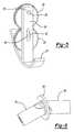
- FIG. 3is a front view illustrating the apparatus
- FIG. 4is an enlarged perspective view illustrating the actuation of a joint between two segments of the apparatus
- FIG. 5is a perspective view illustrating an articulating leg mechanism according to the principles of the present invention.
- FIG. 6is a perspective view of a universal coupling interconnecting drive shafts of adjacent segments of the apparatus
- FIG. 7is a perspective view of a transmission for transmitting power from the drive shaft to the drive leg mechanism
- FIG. 8is a perspective view of the transmission of FIG. 7 having portions removed for clarity;
- FIG. 9is a schematic view illustrating the motion trajectory of the articulating leg mechanism according to the principles of the present invention.
- FIG. 10is a perspective view of an articulating joint according to the principles of the present invention.
- each of the plurality of segments 12includes a plurality of articulating leg mechanisms 14 disposed about the periphery of each segment 12 .
- each of the plurality of segments 12includes four articulating leg mechanisms 14 evenly spaced at 90° intervals about the periphery of each segment 12 to provide a generally continuous series of propulsion members.
- any number of articulating leg mechanismsmay be used so long as they generally extend around the outer diameter or periphery of each segment 12 .
- Adjacent segments 12are joined together via an articulating joint 16 and a drive shaft 18 .
- Apparatus 10may include any number of identical segments 12 connected to each other in a serial fashion.
- the number of segments 12 requireddepends on the terrain that must be covered.
- segments 12may be easily added, removed, or exchanged with other robots.
- the figures contained hereincomprise nine individual segments 12 .
- each of the plurality of articulating leg mechanisms 14includes a leg 20 , a foot 22 , a driven gear 24 , and a drive gear 26 .
- articulating leg mechanism 14includes only one degree of freedom, providing a simplified propulsion system. That is, by having only one degree of freedom per leg, instead of the multiple degrees of freedom like many other legged vehicles, the number of required actuators is reduced, thereby reducing the weight, complexity, and cost of apparatus 10 .
- foot 22is generally arcuate in shape so as to be generally complimentary to an overall outer shape of apparatus 10 .
- the radius of curvature of each foot 22is preferably less than the radius of curvature of a circle C (FIG. 3) swept around apparatus 10 and intersects the outermost point of each foot 22 .
- This arrangementminimizes the potential for sideways rolling of apparatus 10 .
- at least some of articulating leg mechanisms 14 disposed about the periphery of each segment 12will engage a feature of the environment for continued locomotion.
- driven gear 24enmeshingly engages drive gear 26 .
- Driven gear 24includes a pivot pin 28 that is operably received within an aperture 30 of leg 20 .
- drive gear 26includes a cam pin 32 that is operably received within a cam slot 34 of leg 20 .
- pivot pin 28acts within aperture 30 to drive leg 20 in an extending and retracting motion.
- cam pin 32cammingly engages cam slot 34 and drives leg 20 in a sweeping, shoveling, or rotating motion, as illustrated in FIG. 9 .
- the trajectory of foot 22generally includes a lowered portion that is in contact with the ground surface for applying a propelling force to move apparatus 10 and a raised portion that is not in contact with the ground surface to allow for forward placement of foot 22 without interfering with the propelling force applied by other feet 22 .
- Apparatus 10further includes a “head” segment 36 .
- Head segment 36is identical to segment 12 ; however, head segment 36 further includes a plurality of sensors 38 (only one shown) and an onboard computer/controller 40 .
- the plurality of sensors 38may be used to gather environmental data, surveillance data, or any number of other uses.
- Onboard computer 40is used to control the movement of apparatus 10 and to provide a means of controlling and/or communicating with the various systems of apparatus 10 .
- onboard computer 40preferably includes a controller area network (CAN) interface.
- CANcontroller area network
- onboard computer 40receives environmental data, surveillance data, or any number of other data from other onboard sensors located throughout apparatus 10 . The data is then carried to onboard computer 40 via a serial CAN bus.
- CANcontroller area network
- the CANmay then be used to provide a control signal to the plurality of articulating leg mechanisms 14 of apparatus 10 .
- This arrangementreduces the number of electrical wires needed throughout apparatus 10 .
- the mechanical operation of head segment 36is identical to that of segments 12 . Therefore, in the interest of brevity, only a single segment 12 will be discussed in detail, except as otherwise noted.
- Apparatus 10further includes drive shaft 18 .
- Drive shaft 18provides input power to each of the plurality of articulating leg mechanisms 14 via a transmission 42 disposed in each segment 12 .
- Drive shaft 18is a single drive shaft that kinematically links each segment 12 and, more particularly, each articulating leg mechanism 14 .
- drive shaft 18includes a universal joint 44 (FIG. 6) that allows power transfer independent of the relative orientation of segments 12 .
- This arrangementenables all articulating leg mechanisms 14 to be driven by a single actuator, generally indicated at 45 , which supplies torque to drive shaft 18 . It should be appreciated that since all articulating leg mechanisms 14 are kinematically linked by single drive shaft 18 , the phase differences between each articulating leg mechanism 14 are fixed. That is, the phase relationship of articulating leg mechanisms 14 , which defines the gait of apparatus 10 , will remain whatever it was when the robot was assembled.
- actuator 45for supplying power to all articulating leg mechanisms 14 has numerous advantages. Firstly, actuator 45 can be placed on a specially designed segment (not shown) at the tail end of apparatus 10 in such a way as to minimize the load on articulating leg mechanisms 14 , thus reducing the required size of the actuator. Secondly, multiple actuators weigh more than a single actuator that produce the same amount of power, thus the overall weight of apparatus 10 is reduced by using a single actuator for all articulating leg mechanisms 14 . Thirdly, the use of high energy density power sources, such as a small gasoline engine, might be feasible. The energy density of a small gasoline engine with tank is about one order of magnitude greater than that of a comparable electric motor with lithium-ion battery.
- transmission 42interconnects drive shaft 18 with an input shaft 62 of each articulating leg mechanism 14 of each segment 12 .
- Transmission 42includes an inner spur gear 50 that is fixedly coupled to drive shaft 18 for rotation therewith.
- Inner spur gear 50meshes with two idler spur gears 52 (only one shown), which each mesh with an outer spur gear 54 (only one shown).
- Outer spur gear 54is fixedly coupled to a shaft 56 .
- Also fixedly coupled to shaft 56is a worm gear 58 .
- Worm gear 58meshes with two worm gears 60 .
- Each of these four worm gears 60is fixedly coupled to input shaft 62 of articulating leg mechanism 14 .
- Input shaft 62is fixed for rotation with drive gear 26 , which thus drives driven gear 24 and rotates leg 20 and foot 22 through a five-bar geared mechanism as described above to produce the trajectory illustrated in FIG. 9 .
- inner spur gear 50 and outer spur gear 54may each be replaced with a pulley and belt system for power transfer.
- Adjacent segments 12 of apparatus 10are connected using articulating joints 16 (FIGS. 4 and 10 ). Specifically, for discussion purposes, adjacent segments 12 will be referred to as segment 12 a and segment 12 b in FIG. 10 only. Although, it should be appreciated that segments 12 a and 12 b are identical in construction.
- Each articulating joint 16comprises two revolute joints, generally indicated as axis A and axis B, whose axes intersect at an intersection point of articulating joint 16 . These two revolute joints are separated by 90° to provide the two degrees of freedom. As best seen in FIG. 10, these two degrees of freedom are each independently controlled with an actuator or pneumatic piston 64 a and 64 b (generally indicated as 64 elsewhere).
- Each segment 12 a and 12 binclude a pair of arm supports 66 extending from end surfaces 68 thereof (FIGS. 7 and 10 ).
- the pair of arm supports 66are pivotally journalled to a floater bracket 70 via a pair of pivot pins 72 .
- Articulation of joint 16 about axis Ais caused when actuator 64 a, which is mounted on segment 12 a, pushes or pulls a bracket 74 a by means of a rotating crank 76 a. Accordingly, this actuation rotates segment 12 a relative to floater bracket 70 about axis A.
- articulation of joint 16 about axis Bis caused when actuator 64 b, which is mounted on segment 12 b, pushes or pulls a bracket 74 b (located on a backside in FIG. 10) by means of a rotating crank 76 b (located on a backside in FIG. 10 ). Accordingly, this actuation rotates segment 12 b relative to floater bracket 70 about axis B.
- Actuators 64 a and 64 benable apparatus 10 to lift its front end on top of obstacles. This allows apparatus 10 to adjust to the contour of the terrain and overcome obstacles that are orders of magnitude larger than its step height.
- a skinmay be applied around apparatus 10 to protect all internal parts from moisture or sand. However, in some applications, a skin may not be necessary.
- apparatus 10is illustrated as walking on a flat surface, for a simplified discussion model. However, it should be understood that apparatus 10 is capable of traversing rough terrain. As seen in FIG. 3, the front view of apparatus 10 shows that feet 22 of segment 12 touch the ground at two contact points A and B. This is due to the fact that the radius of curvature of feet 22 is smaller than the overall radius of curvature of apparatus 10 , thereby producing generally flat surfaces extending between the ends of adjacent feet 22 on a single segment 12 (see FIG. 3 ). This arrangement reduces the tendency of the otherwise cylindrical robot (when all segments are aligned) to roll. However, it should be understood that these contact points may be at any point about the periphery of apparatus 10 .
- each segment 12may have multiple simultaneous contact points.
- FIG. 2illustrates a worm-like gait.
- head segment 36will be referred to as segment one while the last segment will be referred to as segment nine and the remaining segments numbered consecutively therebetween.
- the two feet 22 that are contacting the ground at each segmentwill be referred to as the right and left feet as apparatus 10 faces forward.
- FIG. 2illustrates a worm-like gait in that the plurality of articulating leg mechanisms 14 disposed on each segment 12 are synchronized to provide a simultaneous driving motion. That is, accordingly to the worm-like gate, all leg mechanisms 14 on a given segment 12 are in phase with the other leg mechanisms 14 on that given segment 12 . However, adjacent segments 12 are out of phase with each other. For example, to achieve a worm-like gait, the left and right feet of segment one would be in a pre-driving position, the left and right feet of segment two would be in a driving position in contact with the ground surface, and the left and right feet of segment three would be in a post-driving position (see FIG. 2 ). Such a worm-like gait is particularly useful for burrowing and/or tunneling into soil.
- an alternating tripod gaitmay be used and is particularly useful for traversing an above-ground surface.
- this alternating tripod gaitthe right foot of segments one and seven, and the left foot of segment four all touch the ground simultaneously in generally a triangular pattern.
- the left foot of segments two and eight, and the right foot of segment fivewill be the next to touch the ground, and so forth.
- each articulating leg mechanism 14is 180° out of phase with the adjacent leg mechanism of the same segment. This arrangement provides a very stable tripod support structure.
- apparatus 10may find utility in a wide variety of applications.
- apparatus 10may be used for fully autonomous search for survivors of earthquakes underneath the rubble of collapsed buildings; military applications in very rugged terrain; mining and autonomous search for other natural resources in terrain that is not accessible to humans (i.e., jungles, mountains, etc.); autonomous burrowing in soft soil; monitoring potential underground radiation leakage of buried radioactive waste; nuclear disaster cleanup (e.g., Chernobyl) and sample retrieval; or research platform for studying many-legged locomotion.
- nuclear disaster cleanupe.g., Chernobyl
- sample retrievalor research platform for studying many-legged locomotion.
Landscapes
- Engineering & Computer Science (AREA)
- Mechanical Engineering (AREA)
- Robotics (AREA)
- Chemical & Material Sciences (AREA)
- Combustion & Propulsion (AREA)
- Transportation (AREA)
- Health & Medical Sciences (AREA)
- General Health & Medical Sciences (AREA)
- Orthopedic Medicine & Surgery (AREA)
- Manipulator (AREA)
Abstract
Description
Claims (31)
Priority Applications (3)
| Application Number | Priority Date | Filing Date | Title |
|---|---|---|---|
| US09/821,867US6512345B2 (en) | 2001-03-30 | 2001-03-30 | Apparatus for obstacle traversion |
| US10/318,452US6774597B1 (en) | 2001-03-30 | 2002-12-12 | Apparatus for obstacle traversion |
| US10/672,290US6870343B2 (en) | 2001-03-30 | 2003-09-26 | Integrated, proportionally controlled, and naturally compliant universal joint actuator with controllable stiffness |
Applications Claiming Priority (1)
| Application Number | Priority Date | Filing Date | Title |
|---|---|---|---|
| US09/821,867US6512345B2 (en) | 2001-03-30 | 2001-03-30 | Apparatus for obstacle traversion |
Related Child Applications (1)
| Application Number | Title | Priority Date | Filing Date |
|---|---|---|---|
| US10/318,452Continuation-In-PartUS6774597B1 (en) | 2001-03-30 | 2002-12-12 | Apparatus for obstacle traversion |
Publications (2)
| Publication Number | Publication Date |
|---|---|
| US20020140392A1 US20020140392A1 (en) | 2002-10-03 |
| US6512345B2true US6512345B2 (en) | 2003-01-28 |
Family
ID=25234482
Family Applications (1)
| Application Number | Title | Priority Date | Filing Date |
|---|---|---|---|
| US09/821,867Expired - Fee RelatedUS6512345B2 (en) | 2001-03-30 | 2001-03-30 | Apparatus for obstacle traversion |
Country Status (1)
| Country | Link |
|---|---|
| US (1) | US6512345B2 (en) |
Cited By (77)
| Publication number | Priority date | Publication date | Assignee | Title |
|---|---|---|---|---|
| US20020171385A1 (en)* | 2001-05-19 | 2002-11-21 | Korea Institute Of Science And Technology | Micro robot |
| US20020173700A1 (en)* | 2001-05-19 | 2002-11-21 | Korea Institute Of Science And Technology | Micro robot |
| US20030229420A1 (en)* | 2000-08-18 | 2003-12-11 | Buckingham Robert Oliver | Robotic positioning of a work tool or sensor |
| US20040140404A1 (en)* | 2002-05-27 | 2004-07-22 | Yoshiji Ohta | Search robot system |
| US20040140786A1 (en)* | 2001-03-30 | 2004-07-22 | Johann Borenstein | Apparatus for obstacle traversion |
| US6832164B1 (en)* | 2001-11-20 | 2004-12-14 | Alfred Stella | Sewerage pipe inspection vehicle having a gas sensor |
| US20050007055A1 (en)* | 2001-03-30 | 2005-01-13 | Johann Borenstein | Integrated, proportionally controlled, and naturally compliant universal joint actuator with controllable stiffness |
| US20050029978A1 (en)* | 2003-07-08 | 2005-02-10 | Dmitry Oleynikov | Microrobot for surgical applications |
| US20050099254A1 (en)* | 2003-11-12 | 2005-05-12 | Ohnstein Thomas R. | Robotic member |
| US20060070775A1 (en)* | 2003-06-17 | 2006-04-06 | Science Applications International Corporation | Toroidal propulsion and steering system |
| US20060119304A1 (en)* | 2003-07-08 | 2006-06-08 | Shane Farritor | Robot for surgical applications |
| US20070079997A1 (en)* | 2005-10-11 | 2007-04-12 | Schlumberger Technology Corporation | Mechanical crawler |
| US20080004634A1 (en)* | 2006-06-22 | 2008-01-03 | Board Of Regents Of The University Of Nebraska | Magnetically coupleable robotic surgical devices and related methods |
| US20080136254A1 (en)* | 2006-11-13 | 2008-06-12 | Jacobsen Stephen C | Versatile endless track for lightweight mobile robots |
| US20080164079A1 (en)* | 2006-11-13 | 2008-07-10 | Jacobsen Stephen C | Serpentine robotic crawler |
| US20080167752A1 (en)* | 2006-11-13 | 2008-07-10 | Jacobsen Stephen C | Tracked robotic crawler having a moveable arm |
| US20080215185A1 (en)* | 2006-11-13 | 2008-09-04 | Jacobsen Stephen C | Unmanned ground robotic vehicle having an alternatively extendible and retractable sensing appendage |
| US20080221591A1 (en)* | 2007-02-20 | 2008-09-11 | Board Of Regents Of The University Of Nebraska | Methods, systems, and devices for surgical visualization and device manipulation |
| US20080281468A1 (en)* | 2007-05-08 | 2008-11-13 | Raytheon Sarcos, Llc | Variable primitive mapping for a robotic crawler |
| US20090025988A1 (en)* | 2007-07-10 | 2009-01-29 | Jacobsen Stephen C | Serpentine Robotic Crawler Having A Continuous Track |
| US20090030562A1 (en)* | 2007-07-10 | 2009-01-29 | Jacobsen Stephen C | Modular Robotic Crawler |
| US20090048612A1 (en)* | 2007-08-15 | 2009-02-19 | Board Of Regents Of The University Of Nebraska | Modular and cooperative medical devices and related systems and methods |
| US20090076536A1 (en)* | 2007-08-15 | 2009-03-19 | Board Of Regents Of The University Of Nebraska | Medical inflation, attachment, and delivery devices and related methods |
| US20090158674A1 (en)* | 2007-12-21 | 2009-06-25 | Schlumberger Technology Corporation | System and methods for actuating reversibly expandable structures |
| US20090171373A1 (en)* | 2007-06-21 | 2009-07-02 | Farritor Shane M | Multifunctional operational component for robotic devices |
| US20100113874A1 (en)* | 2007-04-04 | 2010-05-06 | Marco Quirini | Teleoperated endoscopic capsule |
| US20100174422A1 (en)* | 2009-01-08 | 2010-07-08 | Jacobsen Stephen C | Point And Go Navigation System And Method |
| US20100201185A1 (en)* | 2006-11-13 | 2010-08-12 | Raytheon Sarcos, Llc | Conformable Track Assembly For A Robotic Crawler |
| US20100243274A1 (en)* | 2007-12-21 | 2010-09-30 | Guerrero Julio C | Expandable structure for deployment in a well |
| US20100318242A1 (en)* | 2009-06-11 | 2010-12-16 | Jacobsen Stephen C | Method And System For Deploying A Surveillance Network |
| US20100317244A1 (en)* | 2009-06-11 | 2010-12-16 | Jacobsen Stephen C | Amphibious Robotic Crawler |
| US20110042536A1 (en)* | 2009-08-19 | 2011-02-24 | Thule Organization Solutions, Inc. | Selectively Positionable Device for Securing an Instrument |
| US7896088B2 (en) | 2007-12-21 | 2011-03-01 | Schlumberger Technology Corporation | Wellsite systems utilizing deployable structure |
| US7960935B2 (en) | 2003-07-08 | 2011-06-14 | The Board Of Regents Of The University Of Nebraska | Robotic devices with agent delivery components and related methods |
| US8002716B2 (en) | 2007-05-07 | 2011-08-23 | Raytheon Company | Method for manufacturing a complex structure |
| US20110237890A1 (en)* | 2009-12-17 | 2011-09-29 | Board Of Regents Of The University Of Nebraska | Modular and cooperative medical devices and related systems and methods |
| US20120103705A1 (en)* | 2010-09-30 | 2012-05-03 | Schlee Keith L | Multi-unit mobile robot |
| JP2012240158A (en)* | 2011-05-19 | 2012-12-10 | Tokyo Institute Of Technology | Rotational wave motion mechanism |
| US8343171B2 (en) | 2007-07-12 | 2013-01-01 | Board Of Regents Of The University Of Nebraska | Methods and systems of actuation in robotic devices |
| US8393422B1 (en) | 2012-05-25 | 2013-03-12 | Raytheon Company | Serpentine robotic crawler |
| US8968267B2 (en) | 2010-08-06 | 2015-03-03 | Board Of Regents Of The University Of Nebraska | Methods and systems for handling or delivering materials for natural orifice surgery |
| US9010214B2 (en) | 2012-06-22 | 2015-04-21 | Board Of Regents Of The University Of Nebraska | Local control robotic surgical devices and related methods |
| US9031698B2 (en) | 2012-10-31 | 2015-05-12 | Sarcos Lc | Serpentine robotic crawler |
| US9060781B2 (en) | 2011-06-10 | 2015-06-23 | Board Of Regents Of The University Of Nebraska | Methods, systems, and devices relating to surgical end effectors |
| US9089353B2 (en) | 2011-07-11 | 2015-07-28 | Board Of Regents Of The University Of Nebraska | Robotic surgical devices, systems, and related methods |
| CN105150242A (en)* | 2015-10-15 | 2015-12-16 | 哈尔滨工业大学 | Self-transformation robot module unit and snakelike robot |
| US9409292B2 (en) | 2013-09-13 | 2016-08-09 | Sarcos Lc | Serpentine robotic crawler for performing dexterous operations |
| US9498292B2 (en) | 2012-05-01 | 2016-11-22 | Board Of Regents Of The University Of Nebraska | Single site robotic device and related systems and methods |
| US9566711B2 (en) | 2014-03-04 | 2017-02-14 | Sarcos Lc | Coordinated robotic control |
| CN106625631A (en)* | 2017-02-28 | 2017-05-10 | 哈尔滨工业大学深圳研究生院 | Successive type flexible arm joint group and combined type flexible arm joint group |
| US9743987B2 (en) | 2013-03-14 | 2017-08-29 | Board Of Regents Of The University Of Nebraska | Methods, systems, and devices relating to robotic surgical devices, end effectors, and controllers |
| US9770305B2 (en) | 2012-08-08 | 2017-09-26 | Board Of Regents Of The University Of Nebraska | Robotic surgical devices, systems, and related methods |
| US9888966B2 (en) | 2013-03-14 | 2018-02-13 | Board Of Regents Of The University Of Nebraska | Methods, systems, and devices relating to force control surgical systems |
| US10071303B2 (en) | 2015-08-26 | 2018-09-11 | Malibu Innovations, LLC | Mobilized cooler device with fork hanger assembly |
| US10342561B2 (en) | 2014-09-12 | 2019-07-09 | Board Of Regents Of The University Of Nebraska | Quick-release end effectors and related systems and methods |
| CN110000778A (en)* | 2019-03-24 | 2019-07-12 | 北京化工大学 | A kind of imitative snake robot control method |
| US10376322B2 (en) | 2014-11-11 | 2019-08-13 | Board Of Regents Of The University Of Nebraska | Robotic device with compact joint design and related systems and methods |
| US10582973B2 (en) | 2012-08-08 | 2020-03-10 | Virtual Incision Corporation | Robotic surgical devices, systems, and related methods |
| US10667883B2 (en) | 2013-03-15 | 2020-06-02 | Virtual Incision Corporation | Robotic surgical devices, systems, and related methods |
| US10702347B2 (en) | 2016-08-30 | 2020-07-07 | The Regents Of The University Of California | Robotic device with compact joint design and an additional degree of freedom and related systems and methods |
| US10722319B2 (en) | 2016-12-14 | 2020-07-28 | Virtual Incision Corporation | Releasable attachment device for coupling to medical devices and related systems and methods |
| US10751136B2 (en) | 2016-05-18 | 2020-08-25 | Virtual Incision Corporation | Robotic surgical devices, systems and related methods |
| US10807659B2 (en) | 2016-05-27 | 2020-10-20 | Joseph L. Pikulski | Motorized platforms |
| US10806538B2 (en) | 2015-08-03 | 2020-10-20 | Virtual Incision Corporation | Robotic surgical devices, systems, and related methods |
| CN111846005A (en)* | 2020-07-21 | 2020-10-30 | 山东大学 | A bionic quadruped robot based on a tensegrity structure |
| US10966700B2 (en) | 2013-07-17 | 2021-04-06 | Virtual Incision Corporation | Robotic surgical devices, systems and related methods |
| US11013564B2 (en) | 2018-01-05 | 2021-05-25 | Board Of Regents Of The University Of Nebraska | Single-arm robotic device with compact joint design and related systems and methods |
| US11051894B2 (en) | 2017-09-27 | 2021-07-06 | Virtual Incision Corporation | Robotic surgical devices with tracking camera technology and related systems and methods |
| US11173617B2 (en) | 2016-08-25 | 2021-11-16 | Board Of Regents Of The University Of Nebraska | Quick-release end effector tool interface |
| US11284958B2 (en) | 2016-11-29 | 2022-03-29 | Virtual Incision Corporation | User controller with user presence detection and related systems and methods |
| US11357595B2 (en) | 2016-11-22 | 2022-06-14 | Board Of Regents Of The University Of Nebraska | Gross positioning device and related systems and methods |
| US11883065B2 (en) | 2012-01-10 | 2024-01-30 | Board Of Regents Of The University Of Nebraska | Methods, systems, and devices for surgical access and insertion |
| US11903658B2 (en) | 2019-01-07 | 2024-02-20 | Virtual Incision Corporation | Robotically assisted surgical system and related devices and methods |
| US12150722B2 (en) | 2020-07-06 | 2024-11-26 | Virtual Incision Corporation | Surgical robot positioning system and related devices and methods |
| US12156710B2 (en) | 2011-10-03 | 2024-12-03 | Virtual Incision Corporation | Robotic surgical devices, systems and related methods |
| US12295680B2 (en) | 2012-08-08 | 2025-05-13 | Board Of Regents Of The University Of Nebraska | Robotic surgical devices, systems and related methods |
| US12311550B2 (en) | 2020-12-31 | 2025-05-27 | Sarcos Corp. | Smart control system for a robotic device |
Families Citing this family (22)
| Publication number | Priority date | Publication date | Assignee | Title |
|---|---|---|---|---|
| US20080058989A1 (en)* | 2006-04-13 | 2008-03-06 | Board Of Regents Of The University Of Nebraska | Surgical camera robot |
| KR100662341B1 (en)* | 2004-07-09 | 2007-01-02 | 엘지전자 주식회사 | Display device and its color reproduction method |
| CN101973320B (en)* | 2010-09-21 | 2012-06-13 | 上海大学 | Simulation wriggling walking device |
| CN103341855A (en)* | 2013-06-05 | 2013-10-09 | 燕山大学 | Stretchy snake-shaped robot |
| CN103612683B (en)* | 2013-12-05 | 2015-09-30 | 哈尔滨工程大学 | A kind of crawler-type multi-joint snakelike robot |
| CN104816302B (en)* | 2015-04-27 | 2016-08-31 | 东北大学 | A kind of snakelike Web robot of climbing and climb network method |
| CN105058413B (en)* | 2015-08-12 | 2017-06-20 | 北京化工大学 | Imitative snake search and rescue robot becomes born of the same parents' articulation mechanism |
| AT517856B1 (en)* | 2016-05-20 | 2017-05-15 | Manuel Müller Matthias | robot |
| CN106346462B (en)* | 2016-09-19 | 2019-04-12 | 哈尔滨工业大学深圳研究生院 | A kind of snakelike amphibious robot of modularized joint |
| GB2557179B (en)* | 2016-11-29 | 2020-01-01 | Rolls Royce Plc | Methods, apparatus, computer programs and non-transitory computer readable storage mediums for controlling a hyper redundant manipulator |
| CN106695769B (en)* | 2016-12-29 | 2019-06-04 | 上海理工大学 | A snake-shaped rescue robot |
| CN108161917B (en)* | 2018-03-19 | 2020-12-01 | 上海盾构设计试验研究中心有限公司 | A snakelike arm for shield constructs blade disc and detects |
| CN108189019B (en)* | 2018-03-29 | 2024-01-23 | 燕山大学 | Bionic wheel-foot type pneumatic soft walking robot |
| CN109050706A (en)* | 2018-07-07 | 2018-12-21 | 胡俊 | A kind of obstacle detouring type trolley |
| US20220117461A1 (en)* | 2019-03-25 | 2022-04-21 | W Endoluminal Robotics Ltd. | Manipulator with serial actuation |
| CN110065054B (en)* | 2019-04-09 | 2021-03-16 | 中国科学院自动化研究所 | Multi-section driving master-slave type snake-shaped robot |
| CN110239644B (en)* | 2019-06-04 | 2020-11-03 | 广东省智能制造研究所 | Bionic quadruped robot based on flexible spine technology |
| CN110561388A (en)* | 2019-08-30 | 2019-12-13 | 东北大学 | modular mesh robot |
| CN110842900A (en)* | 2019-11-19 | 2020-02-28 | 国家电网有限公司 | A pipeline robot inspection system and method |
| CN111923032B (en)* | 2020-10-12 | 2020-12-22 | 中国科学院沈阳自动化研究所 | A Modular Reconfigurable Orthogonal Joint Chain Robot |
| CN112276920B (en)* | 2020-10-15 | 2021-10-12 | 北京邮电大学 | Continuum snake-shaped robot |
| CN119302126B (en)* | 2024-11-27 | 2025-09-30 | 吉林大学 | A harvesting agricultural robot with a self-locking mechanism |
Citations (16)
| Publication number | Priority date | Publication date | Assignee | Title |
|---|---|---|---|---|
| US4527650A (en) | 1983-03-18 | 1985-07-09 | Odetics, Inc. | Walking machine |
| US4738583A (en) | 1986-09-30 | 1988-04-19 | The United States Of America As Represented By The Administrator Of The National Aeronautics And Space Administration | Space spider crane |
| US4872524A (en) | 1988-04-13 | 1989-10-10 | Oconnor Chadwell | Wheel-less walking dolly |
| US5145130A (en) | 1991-10-23 | 1992-09-08 | The United States Of America As Represented By The Administrator Of The National Aeronautics & Space Administration | Robot serviced space facility |
| US5255753A (en) | 1989-12-14 | 1993-10-26 | Honda Giken Kogyo Kabushiki Kaisha | Foot structure for legged walking robot |
| US5257669A (en) | 1992-02-10 | 1993-11-02 | The United States Of America As Represented By The Administrator Of The National Aeronautics And Space Administration | Climbing robot |
| US5351626A (en) | 1991-11-11 | 1994-10-04 | Ken Yanagisawa | Walking robot |
| US5351773A (en) | 1992-12-01 | 1994-10-04 | Ken Yanagisawa | Walking robot |
| US5423708A (en) | 1994-08-15 | 1995-06-13 | Allen; Roger D. | Multi-legged, walking toy robot |
| US5644204A (en) | 1994-11-03 | 1997-07-01 | Nagle; John | Anti-slip control for a legged robot and realisitc simulation of a legged creature |
| US5758734A (en) | 1996-01-19 | 1998-06-02 | Korea Institute Of Science And Technology | Foot system for jointed leg type walking robot |
| US5807011A (en) | 1996-10-07 | 1998-09-15 | Korea Institute Of Science And Technology | Foot system for jointed leg type walking robot |
| US5857533A (en) | 1994-04-29 | 1999-01-12 | Alvsjo Data Ab | Vehicle carried and driven by articulated legs |
| US6068073A (en) | 1996-05-10 | 2000-05-30 | Cybernet Systems Corporation | Transformable mobile robot |
| US6105695A (en) | 1996-08-01 | 2000-08-22 | California Institute Of Technology | Multifunction automated crawling system |
| US6178872B1 (en)* | 1998-07-24 | 2001-01-30 | Forschungszentrum Karlsruhe Gmbh | Operating mechanism |
- 2001
- 2001-03-30USUS09/821,867patent/US6512345B2/ennot_activeExpired - Fee Related
Patent Citations (16)
| Publication number | Priority date | Publication date | Assignee | Title |
|---|---|---|---|---|
| US4527650A (en) | 1983-03-18 | 1985-07-09 | Odetics, Inc. | Walking machine |
| US4738583A (en) | 1986-09-30 | 1988-04-19 | The United States Of America As Represented By The Administrator Of The National Aeronautics And Space Administration | Space spider crane |
| US4872524A (en) | 1988-04-13 | 1989-10-10 | Oconnor Chadwell | Wheel-less walking dolly |
| US5255753A (en) | 1989-12-14 | 1993-10-26 | Honda Giken Kogyo Kabushiki Kaisha | Foot structure for legged walking robot |
| US5145130A (en) | 1991-10-23 | 1992-09-08 | The United States Of America As Represented By The Administrator Of The National Aeronautics & Space Administration | Robot serviced space facility |
| US5351626A (en) | 1991-11-11 | 1994-10-04 | Ken Yanagisawa | Walking robot |
| US5257669A (en) | 1992-02-10 | 1993-11-02 | The United States Of America As Represented By The Administrator Of The National Aeronautics And Space Administration | Climbing robot |
| US5351773A (en) | 1992-12-01 | 1994-10-04 | Ken Yanagisawa | Walking robot |
| US5857533A (en) | 1994-04-29 | 1999-01-12 | Alvsjo Data Ab | Vehicle carried and driven by articulated legs |
| US5423708A (en) | 1994-08-15 | 1995-06-13 | Allen; Roger D. | Multi-legged, walking toy robot |
| US5644204A (en) | 1994-11-03 | 1997-07-01 | Nagle; John | Anti-slip control for a legged robot and realisitc simulation of a legged creature |
| US5758734A (en) | 1996-01-19 | 1998-06-02 | Korea Institute Of Science And Technology | Foot system for jointed leg type walking robot |
| US6068073A (en) | 1996-05-10 | 2000-05-30 | Cybernet Systems Corporation | Transformable mobile robot |
| US6105695A (en) | 1996-08-01 | 2000-08-22 | California Institute Of Technology | Multifunction automated crawling system |
| US5807011A (en) | 1996-10-07 | 1998-09-15 | Korea Institute Of Science And Technology | Foot system for jointed leg type walking robot |
| US6178872B1 (en)* | 1998-07-24 | 2001-01-30 | Forschungszentrum Karlsruhe Gmbh | Operating mechanism |
Non-Patent Citations (11)
| Title |
|---|
| "A Safer Way to Search Disaster Sites" by Jennifer Weston, IEEE Robotics & Automation Magazine, Sep. 2000, p. 56-57. |
| "Biomimetic Design and Fabrication of a Hexapedal Running Robot" by Jonathan E. Clark, Jorge G. Cham, Sean A. Bailey, Edward M. Froehlich, Pratik K. Nahata, Robert J. Full, Mark R. Cutkosky, IEEE International Conference on Robotics & Automation, Seoul, Korea, May 21-26, 2001, p. 3643-3649.I. |
| "Controlling a Multijoint Robot for Autonomous Sewer Inspection" by K.-U. Scholl, V. Kepplin, K. Berns, R. Dillmann, IEEE International Conference on Robotics & Automation, San Francisco, CA Apr. 2000, p. 1701-1706. |
| "Design and Control of a Mobile Robot With an Articulated Body" by Shigeo Hirose, Akio Morishima, The International Journal of Robotics Research, vol. 9, No. 2, Apr. 1990, p. 99-113. |
| "Design and Motion Planning of a Mechanical Snake" by Yanson Shan and Yoram Koren, IEEE Transactions on Systems, Man, and Cybernetics, vol. 23, No. 4, Jul./Aug. 1993, p. 1091-1100. |
| "Design and Simulation of a Cockroach-Like Hexapod Robot", by G.M. Nelson, R.D. Quinn, R.J. Bachmann, W.C. Flannigan, IEEE International Conference on Robotics and Automation, Albuquerque, New Mexico, Apr. 1997. |
| "Design of In-Pipe Inspection Vehicles for PHI25, PHI50, PHI150 Pipes" by Shigeo Hirose, Hidetaka Ohno, Takeo Mitsui, Kijchi Suyama, IEEE International Conference on Robotics & Automation, Detroit, MI May 1999, p. 2309-2314. |
| "GMD-SNAKE2: A Snake-Like Robot Driven by Wheels and a Method for Motion Control" by Bernhard Klaassen, Karl L. Paap, IEEE International Conference on Robotics & Automation, Detroit, MI May 1999, p. 3014-3019. |
| "Limbless Locomotion: Learning to Crawl with a Snake Robot" by Kevin J. Dowling, Advised by William L. Whittaker, Dec. 1997. |
| "Limbless Locomotion: Learning to Crawl" by Kevin Dowling, IEEE International Conference on Robotics & Automation, Detroit, MI May 1999, p. 3001-3006. |
| "Design of In-Pipe Inspection Vehicles for Φ25, Φ50, Φ150 Pipes" by Shigeo Hirose, Hidetaka Ohno, Takeo Mitsui, Kijchi Suyama, IEEE International Conference on Robotics & Automation, Detroit, MI May 1999, p. 2309-2314. |
Cited By (179)
| Publication number | Priority date | Publication date | Assignee | Title |
|---|---|---|---|---|
| US20030229420A1 (en)* | 2000-08-18 | 2003-12-11 | Buckingham Robert Oliver | Robotic positioning of a work tool or sensor |
| US7171279B2 (en)* | 2000-08-18 | 2007-01-30 | Oliver Crispin Robotics Limited | Articulating arm for positioning a tool at a location |
| US20040140786A1 (en)* | 2001-03-30 | 2004-07-22 | Johann Borenstein | Apparatus for obstacle traversion |
| US6774597B1 (en)* | 2001-03-30 | 2004-08-10 | The Regents Of The University Of Michigan | Apparatus for obstacle traversion |
| US6870343B2 (en) | 2001-03-30 | 2005-03-22 | The University Of Michigan | Integrated, proportionally controlled, and naturally compliant universal joint actuator with controllable stiffness |
| US20050007055A1 (en)* | 2001-03-30 | 2005-01-13 | Johann Borenstein | Integrated, proportionally controlled, and naturally compliant universal joint actuator with controllable stiffness |
| US20020171385A1 (en)* | 2001-05-19 | 2002-11-21 | Korea Institute Of Science And Technology | Micro robot |
| US20020173700A1 (en)* | 2001-05-19 | 2002-11-21 | Korea Institute Of Science And Technology | Micro robot |
| US6824508B2 (en)* | 2001-05-19 | 2004-11-30 | Korea Institute Of Science And Technology | Micro robot |
| US6824510B2 (en)* | 2001-05-19 | 2004-11-30 | Korea Institute Of Science And Technology | Micro robot |
| US6832164B1 (en)* | 2001-11-20 | 2004-12-14 | Alfred Stella | Sewerage pipe inspection vehicle having a gas sensor |
| US20040140404A1 (en)* | 2002-05-27 | 2004-07-22 | Yoshiji Ohta | Search robot system |
| US7089084B2 (en)* | 2002-05-27 | 2006-08-08 | Sharp Kabushiki Kaisha | Search robot system |
| US20060261771A1 (en)* | 2003-06-17 | 2006-11-23 | Science Applications International Corporation | Toroidal propulsion and steering system |
| US7387179B2 (en) | 2003-06-17 | 2008-06-17 | Science Applications International Corporation | Toroidal propulsion and steering system |
| US20060070775A1 (en)* | 2003-06-17 | 2006-04-06 | Science Applications International Corporation | Toroidal propulsion and steering system |
| US7235046B2 (en) | 2003-06-17 | 2007-06-26 | Science Applications International Corporation | Toroidal propulsion and steering system |
| US7044245B2 (en) | 2003-06-17 | 2006-05-16 | Science Applications International Corporation | Toroidal propulsion and steering system |
| US20060170386A1 (en)* | 2003-06-17 | 2006-08-03 | Science Applications International Corporation | Toroidal propulsion and steering system |
| US20080111513A1 (en)* | 2003-07-08 | 2008-05-15 | Board Of Regents Of The University Of Nebraska | Robot for surgical applications |
| US7372229B2 (en) | 2003-07-08 | 2008-05-13 | Board Of Regents For The University Of Nebraska | Robot for surgical applications |
| US20060196301A1 (en)* | 2003-07-08 | 2006-09-07 | Dmitry Oleynikov | Robot for surgical applications |
| US20090069821A1 (en)* | 2003-07-08 | 2009-03-12 | Board Of Regents Of The University Of Nebraska | Robotic devices with agent delivery components and related methods |
| US20060119304A1 (en)* | 2003-07-08 | 2006-06-08 | Shane Farritor | Robot for surgical applications |
| US7199545B2 (en)* | 2003-07-08 | 2007-04-03 | Board Of Regents Of The University Of Nebraska | Robot for surgical applications |
| US7492116B2 (en)* | 2003-07-08 | 2009-02-17 | Board Of Regents Of The University Of Nebraska | Robot for surgical applications |
| US20070080658A1 (en)* | 2003-07-08 | 2007-04-12 | Shane Farritor | Robot for Surgical Applications |
| US7042184B2 (en)* | 2003-07-08 | 2006-05-09 | Board Of Regents Of The University Of Nebraska | Microrobot for surgical applications |
| US20070241714A1 (en)* | 2003-07-08 | 2007-10-18 | Board Or Regents Of The University Of Nebraska | Robot for surgical applications |
| US7772796B2 (en) | 2003-07-08 | 2010-08-10 | Board Of Regents Of The University Of Nebraska | Robotic devices with agent delivery components and related methods |
| US7339341B2 (en) | 2003-07-08 | 2008-03-04 | Board Of Regents Of The University Of Nebraska | Surgical camera robot |
| US9403281B2 (en) | 2003-07-08 | 2016-08-02 | Board Of Regents Of The University Of Nebraska | Robotic devices with arms and related methods |
| US7126303B2 (en)* | 2003-07-08 | 2006-10-24 | Board Of Regents Of The University Of Nebraska | Robot for surgical applications |
| US20050029978A1 (en)* | 2003-07-08 | 2005-02-10 | Dmitry Oleynikov | Microrobot for surgical applications |
| US8604742B2 (en) | 2003-07-08 | 2013-12-10 | Board Of Regents Of The University Of Nebraska | Robotic devices with arms and related methods |
| US7960935B2 (en) | 2003-07-08 | 2011-06-14 | The Board Of Regents Of The University Of Nebraska | Robotic devices with agent delivery components and related methods |
| US20050099254A1 (en)* | 2003-11-12 | 2005-05-12 | Ohnstein Thomas R. | Robotic member |
| US7154362B2 (en) | 2003-11-12 | 2006-12-26 | Honeywell International, Inc. | Robotic member |
| US20070079997A1 (en)* | 2005-10-11 | 2007-04-12 | Schlumberger Technology Corporation | Mechanical crawler |
| US7617891B2 (en)* | 2005-10-11 | 2009-11-17 | Schlumberger Technology Corporation | Mechanical crawler |
| US8834488B2 (en) | 2006-06-22 | 2014-09-16 | Board Of Regents Of The University Of Nebraska | Magnetically coupleable robotic surgical devices and related methods |
| US8968332B2 (en) | 2006-06-22 | 2015-03-03 | Board Of Regents Of The University Of Nebraska | Magnetically coupleable robotic surgical devices and related methods |
| US10376323B2 (en) | 2006-06-22 | 2019-08-13 | Board Of Regents Of The University Of Nebraska | Multifunctional operational component for robotic devices |
| US20080058835A1 (en)* | 2006-06-22 | 2008-03-06 | Board Of Regents Of The University Of Nebraska | Magnetically coupleable robotic surgical devices and related methods |
| US20080004634A1 (en)* | 2006-06-22 | 2008-01-03 | Board Of Regents Of The University Of Nebraska | Magnetically coupleable robotic surgical devices and related methods |
| US10307199B2 (en) | 2006-06-22 | 2019-06-04 | Board Of Regents Of The University Of Nebraska | Robotic surgical devices and related methods |
| US10959790B2 (en) | 2006-06-22 | 2021-03-30 | Board Of Regents Of The University Of Nebraska | Multifunctional operational component for robotic devices |
| US20080164079A1 (en)* | 2006-11-13 | 2008-07-10 | Jacobsen Stephen C | Serpentine robotic crawler |
| US8042630B2 (en) | 2006-11-13 | 2011-10-25 | Raytheon Company | Serpentine robotic crawler |
| US20080136254A1 (en)* | 2006-11-13 | 2008-06-12 | Jacobsen Stephen C | Versatile endless track for lightweight mobile robots |
| US8205695B2 (en) | 2006-11-13 | 2012-06-26 | Raytheon Company | Conformable track assembly for a robotic crawler |
| US8185241B2 (en)* | 2006-11-13 | 2012-05-22 | Raytheon Company | Tracked robotic crawler having a moveable arm |
| US8002365B2 (en) | 2006-11-13 | 2011-08-23 | Raytheon Company | Conformable track assembly for a robotic crawler |
| US20100201185A1 (en)* | 2006-11-13 | 2010-08-12 | Raytheon Sarcos, Llc | Conformable Track Assembly For A Robotic Crawler |
| US20080167752A1 (en)* | 2006-11-13 | 2008-07-10 | Jacobsen Stephen C | Tracked robotic crawler having a moveable arm |
| US20100258365A1 (en)* | 2006-11-13 | 2010-10-14 | Raytheon Sarcos, Llc | Serpentine Robotic Crawler |
| US20080215185A1 (en)* | 2006-11-13 | 2008-09-04 | Jacobsen Stephen C | Unmanned ground robotic vehicle having an alternatively extendible and retractable sensing appendage |
| US20080221591A1 (en)* | 2007-02-20 | 2008-09-11 | Board Of Regents Of The University Of Nebraska | Methods, systems, and devices for surgical visualization and device manipulation |
| US9579088B2 (en) | 2007-02-20 | 2017-02-28 | Board Of Regents Of The University Of Nebraska | Methods, systems, and devices for surgical visualization and device manipulation |
| US20100113874A1 (en)* | 2007-04-04 | 2010-05-06 | Marco Quirini | Teleoperated endoscopic capsule |
| US8434208B2 (en) | 2007-05-07 | 2013-05-07 | Raytheon Company | Two-dimensional layout for use in a complex structure |
| US8002716B2 (en) | 2007-05-07 | 2011-08-23 | Raytheon Company | Method for manufacturing a complex structure |
| US20080281468A1 (en)* | 2007-05-08 | 2008-11-13 | Raytheon Sarcos, Llc | Variable primitive mapping for a robotic crawler |
| US9179981B2 (en) | 2007-06-21 | 2015-11-10 | Board Of Regents Of The University Of Nebraska | Multifunctional operational component for robotic devices |
| US20090171373A1 (en)* | 2007-06-21 | 2009-07-02 | Farritor Shane M | Multifunctional operational component for robotic devices |
| US8679096B2 (en) | 2007-06-21 | 2014-03-25 | Board Of Regents Of The University Of Nebraska | Multifunctional operational component for robotic devices |
| US20090025988A1 (en)* | 2007-07-10 | 2009-01-29 | Jacobsen Stephen C | Serpentine Robotic Crawler Having A Continuous Track |
| US8571711B2 (en) | 2007-07-10 | 2013-10-29 | Raytheon Company | Modular robotic crawler |
| US20090030562A1 (en)* | 2007-07-10 | 2009-01-29 | Jacobsen Stephen C | Modular Robotic Crawler |
| US9956043B2 (en) | 2007-07-12 | 2018-05-01 | Board Of Regents Of The University Of Nebraska | Methods, systems, and devices for surgical access and procedures |
| US10695137B2 (en) | 2007-07-12 | 2020-06-30 | Board Of Regents Of The University Of Nebraska | Methods, systems, and devices for surgical access and procedures |
| US8828024B2 (en) | 2007-07-12 | 2014-09-09 | Board Of Regents Of The University Of Nebraska | Methods, systems, and devices for surgical access and procedures |
| US8343171B2 (en) | 2007-07-12 | 2013-01-01 | Board Of Regents Of The University Of Nebraska | Methods and systems of actuation in robotic devices |
| US8974440B2 (en) | 2007-08-15 | 2015-03-10 | Board Of Regents Of The University Of Nebraska | Modular and cooperative medical devices and related systems and methods |
| US20090048612A1 (en)* | 2007-08-15 | 2009-02-19 | Board Of Regents Of The University Of Nebraska | Modular and cooperative medical devices and related systems and methods |
| US20090076536A1 (en)* | 2007-08-15 | 2009-03-19 | Board Of Regents Of The University Of Nebraska | Medical inflation, attachment, and delivery devices and related methods |
| US10335024B2 (en) | 2007-08-15 | 2019-07-02 | Board Of Regents Of The University Of Nebraska | Medical inflation, attachment and delivery devices and related methods |
| US20110132626A1 (en)* | 2007-12-21 | 2011-06-09 | Guerrero Julio C | Wellsite systems utilizing deployable structure |
| US20090158674A1 (en)* | 2007-12-21 | 2009-06-25 | Schlumberger Technology Corporation | System and methods for actuating reversibly expandable structures |
| US7896088B2 (en) | 2007-12-21 | 2011-03-01 | Schlumberger Technology Corporation | Wellsite systems utilizing deployable structure |
| US8733453B2 (en) | 2007-12-21 | 2014-05-27 | Schlumberger Technology Corporation | Expandable structure for deployment in a well |
| US20100243274A1 (en)* | 2007-12-21 | 2010-09-30 | Guerrero Julio C | Expandable structure for deployment in a well |
| US9169634B2 (en) | 2007-12-21 | 2015-10-27 | Schlumberger Technology Corporation | System and methods for actuating reversibly expandable structures |
| US8291781B2 (en) | 2007-12-21 | 2012-10-23 | Schlumberger Technology Corporation | System and methods for actuating reversibly expandable structures |
| US20100174422A1 (en)* | 2009-01-08 | 2010-07-08 | Jacobsen Stephen C | Point And Go Navigation System And Method |
| US8392036B2 (en) | 2009-01-08 | 2013-03-05 | Raytheon Company | Point and go navigation system and method |
| US8317555B2 (en) | 2009-06-11 | 2012-11-27 | Raytheon Company | Amphibious robotic crawler |
| US8935014B2 (en) | 2009-06-11 | 2015-01-13 | Sarcos, Lc | Method and system for deploying a surveillance network |
| US20100318242A1 (en)* | 2009-06-11 | 2010-12-16 | Jacobsen Stephen C | Method And System For Deploying A Surveillance Network |
| US20100317244A1 (en)* | 2009-06-11 | 2010-12-16 | Jacobsen Stephen C | Amphibious Robotic Crawler |
| US20110042530A1 (en)* | 2009-08-19 | 2011-02-24 | Mark Phillips | Flexipod with flexible bendable legs with a gripping surface |
| US20110042536A1 (en)* | 2009-08-19 | 2011-02-24 | Thule Organization Solutions, Inc. | Selectively Positionable Device for Securing an Instrument |
| US8894633B2 (en) | 2009-12-17 | 2014-11-25 | Board Of Regents Of The University Of Nebraska | Modular and cooperative medical devices and related systems and methods |
| US20110237890A1 (en)* | 2009-12-17 | 2011-09-29 | Board Of Regents Of The University Of Nebraska | Modular and cooperative medical devices and related systems and methods |
| US8968267B2 (en) | 2010-08-06 | 2015-03-03 | Board Of Regents Of The University Of Nebraska | Methods and systems for handling or delivering materials for natural orifice surgery |
| US20120103705A1 (en)* | 2010-09-30 | 2012-05-03 | Schlee Keith L | Multi-unit mobile robot |
| US8851211B2 (en)* | 2010-09-30 | 2014-10-07 | Keith L. Schlee | Multi-unit mobile robot |
| JP2012240158A (en)* | 2011-05-19 | 2012-12-10 | Tokyo Institute Of Technology | Rotational wave motion mechanism |
| US11832871B2 (en) | 2011-06-10 | 2023-12-05 | Board Of Regents Of The University Of Nebraska | Methods, systems, and devices relating to surgical end effectors |
| US9060781B2 (en) | 2011-06-10 | 2015-06-23 | Board Of Regents Of The University Of Nebraska | Methods, systems, and devices relating to surgical end effectors |
| US10350000B2 (en) | 2011-06-10 | 2019-07-16 | Board Of Regents Of The University Of Nebraska | Methods, systems, and devices relating to surgical end effectors |
| US11065050B2 (en) | 2011-06-10 | 2021-07-20 | Board Of Regents Of The University Of Nebraska | Methods, systems, and devices relating to surgical end effectors |
| US9757187B2 (en) | 2011-06-10 | 2017-09-12 | Board Of Regents Of The University Of Nebraska | Methods, systems, and devices relating to surgical end effectors |
| US11909576B2 (en) | 2011-07-11 | 2024-02-20 | Board Of Regents Of The University Of Nebraska | Robotic surgical devices, systems, and related methods |
| US9089353B2 (en) | 2011-07-11 | 2015-07-28 | Board Of Regents Of The University Of Nebraska | Robotic surgical devices, systems, and related methods |
| US12323289B2 (en) | 2011-07-11 | 2025-06-03 | Board Of Regents Of The University Of Nebraska | Robotic surgical devices, systems, and related methods |
| US10111711B2 (en) | 2011-07-11 | 2018-10-30 | Board Of Regents Of The University Of Nebraska | Robotic surgical devices, systems, and related methods |
| US11032125B2 (en) | 2011-07-11 | 2021-06-08 | Board Of Regents Of The University Of Nebraska | Robotic surgical devices, systems and related methods |
| US11595242B2 (en) | 2011-07-11 | 2023-02-28 | Board Of Regents Of The University Of Nebraska | Robotic surgical devices, systems and related methods |
| US12156710B2 (en) | 2011-10-03 | 2024-12-03 | Virtual Incision Corporation | Robotic surgical devices, systems and related methods |
| US11883065B2 (en) | 2012-01-10 | 2024-01-30 | Board Of Regents Of The University Of Nebraska | Methods, systems, and devices for surgical access and insertion |
| US10219870B2 (en) | 2012-05-01 | 2019-03-05 | Board Of Regents Of The University Of Nebraska | Single site robotic device and related systems and methods |
| US12171512B2 (en) | 2012-05-01 | 2024-12-24 | Board Of Regents Of The University Of Nebraska | Single site robotic device and related systems and methods |
| US11529201B2 (en) | 2012-05-01 | 2022-12-20 | Board Of Regents Of The University Of Nebraska | Single site robotic device and related systems and methods |
| US9498292B2 (en) | 2012-05-01 | 2016-11-22 | Board Of Regents Of The University Of Nebraska | Single site robotic device and related systems and methods |
| US11819299B2 (en) | 2012-05-01 | 2023-11-21 | Board Of Regents Of The University Of Nebraska | Single site robotic device and related systems and methods |
| US8393422B1 (en) | 2012-05-25 | 2013-03-12 | Raytheon Company | Serpentine robotic crawler |
| US9010214B2 (en) | 2012-06-22 | 2015-04-21 | Board Of Regents Of The University Of Nebraska | Local control robotic surgical devices and related methods |
| US10470828B2 (en) | 2012-06-22 | 2019-11-12 | Board Of Regents Of The University Of Nebraska | Local control robotic surgical devices and related methods |
| US11484374B2 (en) | 2012-06-22 | 2022-11-01 | Board Of Regents Of The University Of Nebraska | Local control robotic surgical devices and related methods |
| US10582973B2 (en) | 2012-08-08 | 2020-03-10 | Virtual Incision Corporation | Robotic surgical devices, systems, and related methods |
| US10624704B2 (en) | 2012-08-08 | 2020-04-21 | Board Of Regents Of The University Of Nebraska | Robotic devices with on board control and related systems and devices |
| US11617626B2 (en) | 2012-08-08 | 2023-04-04 | Board Of Regents Of The University Of Nebraska | Robotic surgical devices, systems and related methods |
| US12295680B2 (en) | 2012-08-08 | 2025-05-13 | Board Of Regents Of The University Of Nebraska | Robotic surgical devices, systems and related methods |
| US9770305B2 (en) | 2012-08-08 | 2017-09-26 | Board Of Regents Of The University Of Nebraska | Robotic surgical devices, systems, and related methods |
| US11051895B2 (en) | 2012-08-08 | 2021-07-06 | Board Of Regents Of The University Of Nebraska | Robotic surgical devices, systems, and related methods |
| US11832902B2 (en) | 2012-08-08 | 2023-12-05 | Virtual Incision Corporation | Robotic surgical devices, systems, and related methods |
| US9031698B2 (en) | 2012-10-31 | 2015-05-12 | Sarcos Lc | Serpentine robotic crawler |
| US9888966B2 (en) | 2013-03-14 | 2018-02-13 | Board Of Regents Of The University Of Nebraska | Methods, systems, and devices relating to force control surgical systems |
| US10743949B2 (en) | 2013-03-14 | 2020-08-18 | Board Of Regents Of The University Of Nebraska | Methods, systems, and devices relating to force control surgical systems |
| US11806097B2 (en) | 2013-03-14 | 2023-11-07 | Board Of Regents Of The University Of Nebraska | Methods, systems, and devices relating to robotic surgical devices, end effectors, and controllers |
| US9743987B2 (en) | 2013-03-14 | 2017-08-29 | Board Of Regents Of The University Of Nebraska | Methods, systems, and devices relating to robotic surgical devices, end effectors, and controllers |
| US12070282B2 (en) | 2013-03-14 | 2024-08-27 | Board Of Regents Of The University Of Nebraska | Methods, systems, and devices relating to force control surgical systems |
| US10603121B2 (en) | 2013-03-14 | 2020-03-31 | Board Of Regents Of The University Of Nebraska | Methods, systems, and devices relating to robotic surgical devices, end effectors, and controllers |
| US12336777B2 (en) | 2013-03-14 | 2025-06-24 | Board Of Regents Of The University Of Nebraska | Methods, systems, and devices relating to robotic surgical devices, end effectors, and controllers |
| US11633253B2 (en) | 2013-03-15 | 2023-04-25 | Virtual Incision Corporation | Robotic surgical devices, systems, and related methods |
| US10667883B2 (en) | 2013-03-15 | 2020-06-02 | Virtual Incision Corporation | Robotic surgical devices, systems, and related methods |
| US11826032B2 (en) | 2013-07-17 | 2023-11-28 | Virtual Incision Corporation | Robotic surgical devices, systems and related methods |
| US10966700B2 (en) | 2013-07-17 | 2021-04-06 | Virtual Incision Corporation | Robotic surgical devices, systems and related methods |
| US9409292B2 (en) | 2013-09-13 | 2016-08-09 | Sarcos Lc | Serpentine robotic crawler for performing dexterous operations |
| US9566711B2 (en) | 2014-03-04 | 2017-02-14 | Sarcos Lc | Coordinated robotic control |
| US10342561B2 (en) | 2014-09-12 | 2019-07-09 | Board Of Regents Of The University Of Nebraska | Quick-release end effectors and related systems and methods |
| US12390240B2 (en) | 2014-09-12 | 2025-08-19 | Virtual Incision Corporation | Quick-release end effectors and related systems and methods |
| US11576695B2 (en) | 2014-09-12 | 2023-02-14 | Virtual Incision Corporation | Quick-release end effectors and related systems and methods |
| US12096999B2 (en) | 2014-11-11 | 2024-09-24 | Board Of Regents Of The University Of Nebraska | Robotic device with compact joint design and related systems and methods |
| US10376322B2 (en) | 2014-11-11 | 2019-08-13 | Board Of Regents Of The University Of Nebraska | Robotic device with compact joint design and related systems and methods |
| US11406458B2 (en) | 2014-11-11 | 2022-08-09 | Board Of Regents Of The University Of Nebraska | Robotic device with compact joint design and related systems and methods |
| US10806538B2 (en) | 2015-08-03 | 2020-10-20 | Virtual Incision Corporation | Robotic surgical devices, systems, and related methods |
| US11872090B2 (en) | 2015-08-03 | 2024-01-16 | Virtual Incision Corporation | Robotic surgical devices, systems, and related methods |
| US10071303B2 (en) | 2015-08-26 | 2018-09-11 | Malibu Innovations, LLC | Mobilized cooler device with fork hanger assembly |
| US10814211B2 (en) | 2015-08-26 | 2020-10-27 | Joseph Pikulski | Mobilized platforms |
| CN105150242A (en)* | 2015-10-15 | 2015-12-16 | 哈尔滨工业大学 | Self-transformation robot module unit and snakelike robot |
| US10751136B2 (en) | 2016-05-18 | 2020-08-25 | Virtual Incision Corporation | Robotic surgical devices, systems and related methods |
| US11826014B2 (en) | 2016-05-18 | 2023-11-28 | Virtual Incision Corporation | Robotic surgical devices, systems and related methods |
| US12383355B2 (en) | 2016-05-18 | 2025-08-12 | Virtual Incision Corporation | Robotic surgical devices, systems and related methods |
| US10807659B2 (en) | 2016-05-27 | 2020-10-20 | Joseph L. Pikulski | Motorized platforms |
| US11173617B2 (en) | 2016-08-25 | 2021-11-16 | Board Of Regents Of The University Of Nebraska | Quick-release end effector tool interface |
| US12274517B2 (en) | 2016-08-30 | 2025-04-15 | Board Of Regents Of The University Of Nebraska | Robotic device with compact joint design and an additional degree of freedom and related systems and methods |
| US10702347B2 (en) | 2016-08-30 | 2020-07-07 | The Regents Of The University Of California | Robotic device with compact joint design and an additional degree of freedom and related systems and methods |
| US11813124B2 (en) | 2016-11-22 | 2023-11-14 | Board Of Regents Of The University Of Nebraska | Gross positioning device and related systems and methods |
| US11357595B2 (en) | 2016-11-22 | 2022-06-14 | Board Of Regents Of The University Of Nebraska | Gross positioning device and related systems and methods |
| US12109079B2 (en) | 2016-11-22 | 2024-10-08 | Board Of Regents Of The University Of Nebraska | Gross positioning device and related systems and methods |
| US11284958B2 (en) | 2016-11-29 | 2022-03-29 | Virtual Incision Corporation | User controller with user presence detection and related systems and methods |
| US10722319B2 (en) | 2016-12-14 | 2020-07-28 | Virtual Incision Corporation | Releasable attachment device for coupling to medical devices and related systems and methods |
| US11786334B2 (en) | 2016-12-14 | 2023-10-17 | Virtual Incision Corporation | Releasable attachment device for coupling to medical devices and related systems and methods |
| CN106625631A (en)* | 2017-02-28 | 2017-05-10 | 哈尔滨工业大学深圳研究生院 | Successive type flexible arm joint group and combined type flexible arm joint group |
| US12343098B2 (en) | 2017-09-27 | 2025-07-01 | Virtual Incision Corporation | Robotic surgical devices with tracking camera technology and related systems and methods |
| US11974824B2 (en) | 2017-09-27 | 2024-05-07 | Virtual Incision Corporation | Robotic surgical devices with tracking camera technology and related systems and methods |
| US11051894B2 (en) | 2017-09-27 | 2021-07-06 | Virtual Incision Corporation | Robotic surgical devices with tracking camera technology and related systems and methods |
| US11950867B2 (en) | 2018-01-05 | 2024-04-09 | Board Of Regents Of The University Of Nebraska | Single-arm robotic device with compact joint design and related systems and methods |
| US11504196B2 (en) | 2018-01-05 | 2022-11-22 | Board Of Regents Of The University Of Nebraska | Single-arm robotic device with compact joint design and related systems and methods |
| US12303221B2 (en) | 2018-01-05 | 2025-05-20 | Board Of Regents Of The University Of Nebraska | Single-arm robotic device with compact joint design and related systems and methods |
| US11013564B2 (en) | 2018-01-05 | 2021-05-25 | Board Of Regents Of The University Of Nebraska | Single-arm robotic device with compact joint design and related systems and methods |
| US11903658B2 (en) | 2019-01-07 | 2024-02-20 | Virtual Incision Corporation | Robotically assisted surgical system and related devices and methods |
| CN110000778A (en)* | 2019-03-24 | 2019-07-12 | 北京化工大学 | A kind of imitative snake robot control method |
| CN110000778B (en)* | 2019-03-24 | 2020-12-11 | 北京化工大学 | A control method of a snake-like robot |
| US12150722B2 (en) | 2020-07-06 | 2024-11-26 | Virtual Incision Corporation | Surgical robot positioning system and related devices and methods |
| CN111846005A (en)* | 2020-07-21 | 2020-10-30 | 山东大学 | A bionic quadruped robot based on a tensegrity structure |
| US12311550B2 (en) | 2020-12-31 | 2025-05-27 | Sarcos Corp. | Smart control system for a robotic device |
Also Published As
| Publication number | Publication date |
|---|---|
| US20020140392A1 (en) | 2002-10-03 |
Similar Documents
| Publication | Publication Date | Title |
|---|---|---|
| US6512345B2 (en) | Apparatus for obstacle traversion | |
| US6774597B1 (en) | Apparatus for obstacle traversion | |
| US8571711B2 (en) | Modular robotic crawler | |
| CN102141181B (en) | Serpentine robotic crawler | |
| US8042630B2 (en) | Serpentine robotic crawler | |
| US9616948B2 (en) | Active docking mechanism for modular and reconfigurable robots | |
| CN107830307B (en) | A highly maneuverable inchworm-type peristaltic robot | |
| US20090039819A1 (en) | Walk and roll robot | |
| US20110040427A1 (en) | Hybrid mobile robot | |
| Granosik | Hypermobile robots–the survey | |
| Michaud et al. | AZIMUT, a leg-track-wheel robot | |
| KR101304107B1 (en) | Robot for stairs climbing | |
| WO2013177561A1 (en) | Serpentine robotic crawler | |
| EP1957349A1 (en) | Dual tracked mobile robot for motion in rough terrain | |
| EP2117783A2 (en) | Vehicle with mobility enhancing arm | |
| CN107848585B (en) | Caterpillars and traveling equipment | |
| Kang et al. | ROBHAZ-DT2: Design and integration of passive double tracked mobile manipulator system for explosive ordnance disposal | |
| Granosik et al. | Serpentine robots for industrial inspection and surveillance | |
| CN211809923U (en) | Investigation robot with four-foot auxiliary wheel | |
| Lane et al. | A 2-D tread mechanism for hybridization in USAR robotics | |
| CN211731625U (en) | Multi-shaft mechanical leg | |
| Kumar et al. | Snake robots for rescue operation | |
| Kang et al. | ROBHAZ-DT2: Passive double-tracked mobile manipulator for explosive ordnance disposal | |
| Chen et al. | Design and realization of a mobile wheelchair robot for all terrains | |
| Granosik | Hypermobile robots |
Legal Events
| Date | Code | Title | Description |
|---|---|---|---|
| AS | Assignment | Owner name:UNITED STATES DEPARTMENT OF ENERGY, DISTRICT OF CO Free format text:CONFIRMATORY LICENSE;ASSIGNOR:UNIVERSITY OF MICHIGAN, THE;REEL/FRAME:011872/0189 Effective date:20010511 | |
| AS | Assignment | Owner name:REGENTS OF THE UNIVERSITY OF MICHIGAN, THE, MICHIG Free format text:ASSIGNMENT OF ASSIGNORS INTEREST;ASSIGNORS:BORENSTEIN, JOHANN;LONG, GEOFFREY A.;REEL/FRAME:012009/0361;SIGNING DATES FROM 20010417 TO 20010427 | |
| FEPP | Fee payment procedure | Free format text:PAYOR NUMBER ASSIGNED (ORIGINAL EVENT CODE: ASPN); ENTITY STATUS OF PATENT OWNER: SMALL ENTITY | |
| REFU | Refund | Free format text:REFUND - PAYMENT OF MAINTENANCE FEE, 4TH YEAR, LARGE ENTITY (ORIGINAL EVENT CODE: R1551); ENTITY STATUS OF PATENT OWNER: SMALL ENTITY | |
| FPAY | Fee payment | Year of fee payment:4 | |
| REMI | Maintenance fee reminder mailed | ||
| LAPS | Lapse for failure to pay maintenance fees | ||
| STCH | Information on status: patent discontinuation | Free format text:PATENT EXPIRED DUE TO NONPAYMENT OF MAINTENANCE FEES UNDER 37 CFR 1.362 | |
| FP | Lapsed due to failure to pay maintenance fee | Effective date:20110128 |