US6512194B1 - Multi-arm weld gun - Google Patents
Multi-arm weld gunDownload PDFInfo
- Publication number
- US6512194B1 US6512194B1US09/715,727US71572700AUS6512194B1US 6512194 B1US6512194 B1US 6512194B1US 71572700 AUS71572700 AUS 71572700AUS 6512194 B1US6512194 B1US 6512194B1
- Authority
- US
- United States
- Prior art keywords
- weld gun
- jaw
- actuator
- weld
- arm
- Prior art date
- Legal status (The legal status is an assumption and is not a legal conclusion. Google has not performed a legal analysis and makes no representation as to the accuracy of the status listed.)
- Expired - Fee Related, expires
Links
Images


Classifications
- B—PERFORMING OPERATIONS; TRANSPORTING
- B23—MACHINE TOOLS; METAL-WORKING NOT OTHERWISE PROVIDED FOR
- B23K—SOLDERING OR UNSOLDERING; WELDING; CLADDING OR PLATING BY SOLDERING OR WELDING; CUTTING BY APPLYING HEAT LOCALLY, e.g. FLAME CUTTING; WORKING BY LASER BEAM
- B23K11/00—Resistance welding; Severing by resistance heating
- B23K11/30—Features relating to electrodes
- B23K11/31—Electrode holders and actuating devices therefor
- B23K11/314—Spot welding guns, e.g. mounted on robots
- B—PERFORMING OPERATIONS; TRANSPORTING
- B23—MACHINE TOOLS; METAL-WORKING NOT OTHERWISE PROVIDED FOR
- B23K—SOLDERING OR UNSOLDERING; WELDING; CLADDING OR PLATING BY SOLDERING OR WELDING; CUTTING BY APPLYING HEAT LOCALLY, e.g. FLAME CUTTING; WORKING BY LASER BEAM
- B23K11/00—Resistance welding; Severing by resistance heating
- B23K11/30—Features relating to electrodes
- B23K11/31—Electrode holders and actuating devices therefor
- B23K11/312—Electrode holders and actuating devices therefor for several electrodes
- B—PERFORMING OPERATIONS; TRANSPORTING
- B23—MACHINE TOOLS; METAL-WORKING NOT OTHERWISE PROVIDED FOR
- B23K—SOLDERING OR UNSOLDERING; WELDING; CLADDING OR PLATING BY SOLDERING OR WELDING; CUTTING BY APPLYING HEAT LOCALLY, e.g. FLAME CUTTING; WORKING BY LASER BEAM
- B23K11/00—Resistance welding; Severing by resistance heating
- B23K11/30—Features relating to electrodes
- B23K11/31—Electrode holders and actuating devices therefor
- B23K11/314—Spot welding guns, e.g. mounted on robots
- B23K11/315—Spot welding guns, e.g. mounted on robots with one electrode moving on a linear path
Definitions
- the present inventionrelates to electric welding assemblies having multiple weld gun arms for producing multiple simultaneous welds in a single pass.
- the present inventionrelates to assemblies where one arm of a multiple arm weld gun is retractable.
- Resistance weldingutilizes the flow of electricity to permanently join two or more overlapping metallic work pieces to one another.
- the metallic work piecesare placed between two opposing electrode tips, which are on the jaws of a weld gun arm.
- the electrodesare then forced together until their tips contact the outer surfaces of the work pieces at a pressure sufficient to sandwich the work pieces and ensure an adequate electrical contact between the electrode tips and the work pieces.
- An electrical currentis induced to flow from one electrode tip to the other electrode tip by way of the sandwiched work pieces.
- the work piecesact as conductors in the resulting electrical circuit, and resistance to the flow of electrical current at the interfaces between the metals generates heat.
- the affected metal of each work piecesselectively becomes molten, and interacts with molten metal of an adjacent work pieces to form a weld nugget that permanently bonds the work pieces together at the point of electrode tip contact.
- a number of factorsrelate to the creation of a weld nugget, including the force and area of contact between the electrode tips and the work pieces, the level of current flow, the length of time the current flow lasts, degree of work pieces imperfection, and even the condition of the electrode tips themselves.
- weld guns used in manufacturing processestypically are required to make multiple consecutive welds on a given work pieces.
- devicesexist for moving the work pieces between individual welds, moving the weld gun between individual welds, or both.
- the electric welding gunmay cycle through various locations, i.e. between an operational position with a work pieces and a resting position.
- the work piecesmay be placed on a moving platform that manipulates the work pieces for a welding operation with a movable weld gun.
- the weld gunmay move toward the work pieces to perform a weld cycle, after which the weld gun moves away from the work pieces to allow movement of the piece and manipulation of the next piece to be welded.
- the weld gunmust make a significant number of consecutive welds before further manipulation of the work pieces. In such applications, the amount of time required to move the weld gun to make the consecutive welds becomes a rate limiting step.
- the processincludes creating welds by closing electrode tips of the weld guns about the work pieces, creating welds, reorienting the multiple arm weld gun with respect to the work pieces, and creating additional welds.
- Multiple arm weld gunsare thus able to complete more than one weld at once, depending upon the number of weld arms on the weld gun, thereby shortening the period of time it takes to complete all the welds on a work pieces.
- the weld cycle periodis shortened, i.e. the period of time from the beginning of one work pieces to the beginning of the next work pieces is decreased.
- a multiple arm weld gunwherein one or more weld gun arms on the multiple arm weld gun are able to retract away from a work pieces while at least one other arm remains operational, thus allowing a multiple arm weld gun to act as a single arm weld gun.
- the remaining weld gun armsmay be repositioned with respect to the work pieces in a space not previously accessible to the multiple arm weld gun before retraction of an arm.
- all weld gun armsmay be retractable, preferably only at least one arm is not retractable. The ability to retract all but one of the weld gun arms effectively overcomes the problem of multiple arm weld guns that are too large, without requiring the use of a separate single arm weld gun.
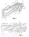
- FIG. 1is perspective view of a dual arm weld gun.
- FIG. 2is a side view of a dual arm weld gun.
- FIG. 3is a side view of a second embodiment.
- FIG. 4is a side view of a third embodiment.
- At least one actuatoris required per weld gun arm to provide the force necessary to make a weld stroke, which includes opening and closing the jaws of the weld gun arm at the spot of the weld on an engaged work pieces and providing the necessary compressive force to achieve a tight electrical contact between the electrode and the work pieces.
- at least two actuatorsare required, i.e. one for each weld gun arm. Any known actuators may be used, as well as any known toggle link and actuator combination.
- a dual arm weld gun 10includes a first C-shaped weld gun arm 11 having a generally C-shaped fixed jaw 12 in combination with a second C-shaped weld gun arm 13 to form a multiple weld gun arm. It should be understood that more than two weld gun arms may be interconnected to form a multiple arm weld gun. Additionally, while the below description is directed primarily to only first C-shaped weld gun arm 11 , it should be understood that the description may apply to one or more arms of a multiple arm weld gun.
- Fixed jaw 12 of first weld gun 11includes a first end 14 , a second end 16 and an electrode tip 18 at a distal end of the first end 14 .
- Weld gun arm 11also includes a moveable jaw 20 having a first end 22 , a second end 24 , an electrode tip 26 at a distal end of the first end 22 , and a guide 28 that is preferably linear.
- Linear guide structure 28includes a guide rail 29 received in a bracket 31 , which ensures that during normal welding operation, movable jaw 20 moves only along a fixed, preset path.
- Weld gun arm 11further comprises an actuator 30 having an actuator shaft 32 connected to movable jaw 20 .
- shaft 32is fixedly connected to movable jaw 20 through connector 40 .
- the size and shape of connector 40may vary as necessary to prevent unwanted interaction between shaft 32 of the actuator 30 and guide 28 .
- actuator 30is a linear actuator capable of moving only in a fore and aft direction during normal operation. As such, the interconnection of shaft 32 with connector 40 and of connector 40 to movable jaw 20 limits movement of the movable jaw 20 to only a fixed, preset path that is preferably linear during normal operation.
- fixed jaw 11is connected to at least one mounting bracket 34 at the second end 16 of the fixed jaw 11 .
- bracket 31 of the linear guide structure 28is also connected to mounting bracket 34 at a locking joint that allows rotational movement, such as by a clutch plate 36 .
- clutch plate 36is mounted on bracket 34 having a central axis of rotation 38 defined through the center of the clutch plate 36 .
- both fixed and movable jaws 11 , 20are operably connected to the clutch plate 36 for rotational movement about axis 38 .
- second ends 16 of fixed jaw 11enclose portions of linear guide 28 attached to the movable jaw 20 .
- the connector 40also serves to operably interconnect actuator 30 with fixed and movable jaws 11 , 20 .
- actuator 30also serves to operably interconnect actuator 30 with fixed and movable jaws 11 , 20 .
- the entire weld gun arm, including fixed and movable jaws 11 , 20 as well as the actuator 30 and actuator shaft 32is functionally connected to clutch plate 36 on bracket 34 .
- clutch plate 34is locked against rotation about axis 38 .
- a work piecesmay be positioned between electrodes 18 , 26 .
- Movable electrode 26 on movable jaw 20is cycled on a fixed, preset path, preferably linear, by operation of actuator 30 .
- actuator 30cycles actuator shaft 32 fore and aft as necessary to accomplish welding. Since shaft 32 is operably connected to movable jaw 20 , movable jaw 20 likewise cycles fore and aft in response to movement of shaft 32 .
- actuator 30extends the actuator shaft 32 in a first direction, the distance between the electrode tips 18 , 26 decreases until the electrode tips are in an engaged position in contact with the work pieces (not shown).
- the actuator 30withdraws the actuator shaft 32 in a second direction to release the work pieces and return the weld gun 10 to a disengaged position, depicted in FIGS. 1 and 2.
- the normal weld strokemay be repeated as necessary until such time that a weld is needed in a spatially restricted portion of the work pieces.
- a retraction stroketakes place, as described below, to retract weld gun 10 to allow the remaining unencumbered weld gun arm to continue normal operation creating additional welds on the work pieces.
- the actuator 30may withdraw the actuator shaft 32 in the disengaged direction beyond the disengaged position to provide the force necessary to rotate the weld gun arm 11 including jaws 12 and 20 to a retracted position.
- all structural components of the weld gun arm 10are operably connected to the clutch plate 36 , which is normally locked against rotation.
- clutch plate 36disengages, thereby allowing rotation of weld gun 10 about axis 38 , while actuator 30 provides the force necessary to rotate the gun.
- Clutch plate 36may be electrically engaged and spring disengaged, or vice versa, or may use any suitable engagement and disengagement mechanism.
- actuator 30withdraws actuator shaft 32 beyond the disengaged position. As actuator shaft 32 is withdrawn further toward a retracted position, not only does the actuator create a linear force along its path of movement, it also causes a downward force to be exerted on the jaws 12 , 20 .
- the downward force exerted on jaws 12 , 20causes rotation the plate 36 , thereby causing the weld gun 10 to rotate in a downwardly direction, as shown in phantom in FIG. 2 .
- the weld gun arm 11is moved to a retracted position such that the arm 11 will not interfere with the remaining arm 13 as it performs additional welds in a confined space on mating work pieces.
- a dual arm weld gunmay quickly, easily and reversibly be transformed into a single weld gun arm, or into a weld gun utilizing less than all of its weld gun arms if there are more than two arms.
- bracket 34further includes a cam track 50 formed at a point on bracket 34 adjacent actuator 30 or actuator shaft 32 .
- a cam follower 52is affixed along the longitudinal length of the actuator shaft 32 and is slidably engaged in the cam track 50 .
- Cam track 50includes a predetermined cam surface 54 along which cam follower 52 slides.
- the cam track 50includes two portions, but any conventional design may be employed.
- a first portion 56 of the cam track 50is preferably linear and parallel to the normal position of both linear guide 28 and actuator shaft 32 .
- cam follower 52resides only in the first portion 56 of cam track 50 , which defines motion between engaged and disengaged positions.
- a second portion 58 of the cam track 50is preferably arcuately shaped to define a path of travel for gun 10 during a retraction operation, as described more fully below.
- cam follower 52moves within cam track 50 from the generally linear first portion 56 to the arcuate second portion 58 .
- Arcuate second portion 58 of cam track 50is designed and shaped to cause gun 10 to rotate about axis 38 .
- all portions of weld gun 10 that are operationally connected to clutch plate 36rotate with clutch plate 36 about axis 38 .
- the second portion 58 of cam track 50angles upwardly with respect to actuator shaft 32 , thereby causing the assembly to rotate in a downwardly direction, as shown in phantom in FIG. 2 .
- the weld gun 10 of FIGS. 1 and 2utilizes a linear actuator to translate linear motion into rotation of the weld gun 10 about a rotational joint.
- a linear actuatorto translate linear motion into rotation of the weld gun 10 about a rotational joint.
- other conventional types of pivoting or rotational jointsare also suitable, such as joints that facilitate a linear sliding motion or a corkscrew motion.
- a single stage actuator or motoris used to provide the force and movement required for both the weld stroke and the retraction stroke by working in combination with the locking joint.
- a two stage actuator or motormay be used to effect both the weld stroke and the retraction stroke.
- a strategically placed stop or appropriately designed cam trackmay also be utilized to facilitate a retraction stroke using a two stage actuator.
- a retractable weld gun utilizing a two stage actuatoris shown in FIG. 3.
- a caliper-type weld gun arm 110is shown, representing one arm of a multiple arm weld gun.
- Weld gun arm 110includes a fixed jaw 112 having a first end 114 and a second end 116 .
- Fixed jaw first end 114terminates in electrode tip 118 .
- the weld gun arm 110further includes a moveable jaw 120 having a first end 122 inwardly directed towards fixed jaw first end 114 , a second end 124 .
- Movable jaw first end 122likewise terminates in an electrode tip 126 in a position opposed to tip 118 .
- connection point 134Fixed and movable jaws are rotationally interconnected at a connection point 134 such that opposed electrodes 118 , 126 may rotationally move toward and away from each other during a weld stroke.
- Fixed jaw 112is further connected to a mounting bracket 138 at a selectively lockable second connection point 136 .
- Second connection point 136usually acts as a rigid connection point that selectively prevents rotation of fixed jaw 112 about the second connection point. However, if further retraction of gun 110 is required, second connection point 136 may be unlocked to act as a rotational connection similar to first connection point 134 , thereby allowing fixed jaw 112 to rotate about second connection point 136 , as described further below.
- Weld gun arm 110further includes an actuator 130 , preferably mounted on bracket 138 , having an actuator shaft 132 .
- Actuator shaft 132is rotationally connected at a third connection point 141 to the second end 124 of the moveable jaw 120 .
- a stop 140is connected to the second end 116 of the fixed jaw 112 .
- actuator 130extends shaft 132 , forcing movable jaw 120 to rotate about first connection point 134 , thereby decreasing the distance between tips 118 , 126 until the electrode tips are in contact with the work pieces (not shown) in an engaged position. Electricity is passed between the electrode tips 118 , 126 and through the work pieces to create the weld nugget. This is the weld stroke.
- the actuator 130withdraws the actuator shaft 132 to a disengaged position to release the mated work pieces so that arm 110 or the work pieces may be repositioned with respect to the other.
- This weld strokemay be repeated until such time that a weld is needed in a spatially restricted portion of the work pieces. Then a retraction stroke takes place, as described below, after which, the remaining weld gun arm or arms may create additional welds on the work pieces.
- second connection point 136selectively disengages from a rigid connection to a rotatable connection. Selective engagement and disengagement of second connection point 136 may be accomplished by any conventional means. Under normal operation, the maximum withdrawal of actuator shaft 132 , and by association, the maximum distance between electrode tips 118 , 126 , is limited by stop 140 . However, by selectively disengaging second connection point 136 , continued withdrawal of the actuator shaft 132 by the actuator 130 forces the combined fixed jaw 112 and moveable jaw 120 to rotate as a single unit about both first connection point 134 and second connection point 136 .
- the linear motion of the actuator 130is thereby translated into rotational motion of the jaws 112 , 120 , causing both jaws to rotate upwardly with respect to bracket 138 in FIG. 3 .
- the rotation about the connections 134 , 136effectively swings the weld gun arm away from the work pieces so that additional welds may be made on a spatially restricted portion of the work pieces.
- the cam track/cam follower mechanism used in FIGS. 1 and 3may also be adapted to bayonet style weld guns.
- a cam followeris fixedly attached to a moveable jaw of bayonet style weld gun arm, while a cam track is located on a fixed jaw of the weld gun arm.
- the cam trackIn a first portion, the cam track is straight and guides the movable jaw along a fixed, preset preferably linear path between a disengaged and an engaged position.
- a second portion of the cam trackis preferably angled away from the first portion, causing the movable jaw to retract in response to action of the cam follower within the cam track.
- a bayonet style weld gun 210is shown in FIG. 4 .
- gun arm 210is only one arm of a multiple arm weld gun.
- the weld gun arm 210comprises a generally C-shaped fixed jaw 212 having a first end 214 terminating in an electrode tip 218 and a second end 216 .
- Fixed jaw 212is pivotally mounted at connection point 236 to a mounting bracket 238 .
- the weld gun arm 210further includes a moveable jaw 220 having a first end 222 and a second end 224 .
- Movable jaw first end 222terminates in an electrode tip 226 such that tips 218 , 226 are arranged in an opposed manner.
- Movable jaw 220further includes a cam follower 228 mounted on a bracket 229 as necessary such that the cam follower slidably engages a cam track 234 located on fixed jaw 212 .
- An actuator 230moving along a fixed, preset path, and preferably a linear actuator having an actuator shaft 232 , is connected to the movable jaw second end 224 to impart fore and aft motion to the movable jaw 220 .
- movable jaw 220moves generally linearly towards fixed jaw first end 214 .
- Movable jaw 220is guided in its motion through the action of cam follower 228 sliding within cam track 234 .
- shaft 232moves from a disengaged to an engaged position, the distance between the electrode tips 218 , 126 decreases until the electrode tips are in contact with the work pieces (not shown). Electricity is passed between the electrode tips 218 , 226 and through the work pieces to create the weld nugget. This is the weld stroke.
- the actuator 230withdraws the actuator shaft 232 to release the work pieces and return the weld gun arm 210 to a disengaged position.
- This weld strokemay be repeated until such time that a weld is needed in a spatially restricted portion of the work pieces. Then a retraction stroke takes place, as described below, after which, any remaining weld gun arms may create additional welds on the mated work pieces.
- cam track 234has two portions.
- a first portion 240is generally linear and parallel to the motion of the actuator 230 , thereby describing a fixed, preset path corresponding to normal operation.
- the cam follower 228slides in this portion of the cam track 234 without significantly moving the fixed jaw 212 because the fixed length cam follower 228 is moving parallel to the motion of the actuator 230 .
- a second portion 242 of the cam track 234angles toward the moveable jaw 220 to cause the fixed jaw 212 to pivot about connection 232 as the fixed jaw 212 is drawn toward the movable jaw 222 .
- the motion of the fixed jaw 212 during the retraction strokeis defined by the shape of the cam track 234 .
Landscapes
- Engineering & Computer Science (AREA)
- Mechanical Engineering (AREA)
- Robotics (AREA)
- Resistance Welding (AREA)
Abstract
Description
Claims (15)
Priority Applications (1)
| Application Number | Priority Date | Filing Date | Title |
|---|---|---|---|
| US09/715,727US6512194B1 (en) | 1999-11-19 | 2000-11-17 | Multi-arm weld gun |
Applications Claiming Priority (3)
| Application Number | Priority Date | Filing Date | Title |
|---|---|---|---|
| US16644999P | 1999-11-19 | 1999-11-19 | |
| US16651099P | 1999-11-19 | 1999-11-19 | |
| US09/715,727US6512194B1 (en) | 1999-11-19 | 2000-11-17 | Multi-arm weld gun |
Publications (1)
| Publication Number | Publication Date |
|---|---|
| US6512194B1true US6512194B1 (en) | 2003-01-28 |
Family
ID=26862280
Family Applications (1)
| Application Number | Title | Priority Date | Filing Date |
|---|---|---|---|
| US09/715,727Expired - Fee RelatedUS6512194B1 (en) | 1999-11-19 | 2000-11-17 | Multi-arm weld gun |
Country Status (3)
| Country | Link |
|---|---|
| US (1) | US6512194B1 (en) |
| AU (1) | AU1771601A (en) |
| WO (1) | WO2001036141A1 (en) |
Cited By (10)
| Publication number | Priority date | Publication date | Assignee | Title |
|---|---|---|---|---|
| US20030173793A1 (en)* | 1998-06-18 | 2003-09-18 | Karl-Otto Stromberg | Tool holder |
| US20040134888A1 (en)* | 2003-01-09 | 2004-07-15 | Frank Garza | Servo spot welding control system and method of welding workpieces |
| USD523044S1 (en)* | 2003-11-24 | 2006-06-13 | S.W.A.C. Schmitt-Walter Automation Consult Gmbh | Welding tongs |
| ITUD20090050A1 (en)* | 2009-02-25 | 2010-08-26 | Tecnodinamica S R L | WELDING PLIERS |
| US20120043308A1 (en)* | 2010-06-23 | 2012-02-23 | Yoshio Sato | Equalizing mechanism of welding apparatus |
| US20150090699A1 (en)* | 2013-09-30 | 2015-04-02 | Hyundai Motor Company | Spot welding apparatus |
| US9238280B2 (en) | 2013-03-15 | 2016-01-19 | Honda Motor Co., Ltd. | Dual shift unit for welder |
| CN106041279A (en)* | 2016-08-17 | 2016-10-26 | 合肥亿翔自动化装备有限公司 | Simple manual assist welding mechanism |
| US12017295B2 (en) | 2021-02-10 | 2024-06-25 | The Esab Group Inc. | Torch with adjustable features |
| US12318856B2 (en) | 2021-02-10 | 2025-06-03 | The Esab Group Inc. | Telescoping torch |
Families Citing this family (2)
| Publication number | Priority date | Publication date | Assignee | Title |
|---|---|---|---|---|
| CN105234540A (en)* | 2014-06-18 | 2016-01-13 | 佛山市顺德区德芯智能科技有限公司 | Automatic butt welding machine |
| FR3077748B1 (en)* | 2018-02-13 | 2020-02-14 | Fts Welding | WELDING GRIPPER INCLUDING A ROTATING ARM WITH LIMITED WEAR AND QUICK DISASSEMBLY |
Citations (64)
| Publication number | Priority date | Publication date | Assignee | Title |
|---|---|---|---|---|
| US3205337A (en)* | 1964-05-28 | 1965-09-07 | Budd Co | Portable welding gun |
| FR2118096A1 (en) | 1970-12-18 | 1972-07-28 | Bbc Brown Boveri & Cie | Capillary layer alloy - for lining electric heat stressed conductors |
| DE2305529A1 (en) | 1973-02-05 | 1974-08-15 | Ernst Knoerzer | Cooling electrodes of resistance welding machines - by evaporating coolant in or adjacent the electrodes |
| US4162387A (en) | 1977-03-14 | 1979-07-24 | Ettore De Candia | Car body welding assembly system |
| WO1980000229A1 (en) | 1978-07-21 | 1980-02-21 | Volvo Ab | Electrical resistance welding apparatus |
| FR2447126A1 (en) | 1979-01-16 | 1980-08-14 | Stein Surface | Liq. cooled electrical measurement contact - has removable contact piece and contact shaft with blades for dissipating heat in cooling liq. |
| US4233488A (en) | 1977-11-23 | 1980-11-11 | Schwartz Charles A | Deep throat resistance welder |
| US4280182A (en) | 1979-05-14 | 1981-07-21 | John Mickowski | Microcomputer control system |
| JPS56160885A (en) | 1980-05-14 | 1981-12-10 | Nippon Abionikusu Kk | Resistance welding equipment |
| JPS58165307A (en) | 1982-03-26 | 1983-09-30 | Toshiba Corp | transformer |
| US4488135A (en) | 1982-07-29 | 1984-12-11 | Schwartz Charles A | Transformer for welding gun |
| US4503312A (en) | 1981-06-10 | 1985-03-05 | Nissan Motor Company, Limited | Method and apparatus for controlling resistance welding |
| EP0133929A2 (en) | 1983-07-29 | 1985-03-13 | Bayerische Motoren Werke Aktiengesellschaft, Patentabteilung AJ-3 | Welding tongs for the resistance-welding of work pieces |
| US4577085A (en) | 1984-01-20 | 1986-03-18 | Marelco Power Systems, Inc. | System of transformers for a welding apparatus |
| JPS61150786A (en) | 1984-12-24 | 1986-07-09 | Nissan Motor Co Ltd | Spot welding method |
| US4656327A (en) | 1985-08-23 | 1987-04-07 | Wilcox Paul A | Spot welder with electrode clamp |
| US4661680A (en) | 1985-06-28 | 1987-04-28 | Westinghouse Electric Corp. | End-of-arm tooling carousel apparatus for use with a robot |
| US4703158A (en)* | 1986-03-31 | 1987-10-27 | Marelco Power Systems, Inc. | High frequency welding system |
| US4728137A (en) | 1986-07-22 | 1988-03-01 | American Engineering And Trade, Inc. | Compound toggle robotic gripper |
| US4760633A (en) | 1985-12-17 | 1988-08-02 | Utica Enterprises, Inc. | Method for body panel attachment |
| US4813125A (en) | 1987-06-08 | 1989-03-21 | Utica Enterprises, Inc. | Method and apparatus for establishing the position of a datum reference from an object having dimensional variations within a tolerance range |
| US4827595A (en) | 1985-12-05 | 1989-05-09 | Utica Engineering Company | Method for hemming overlapped sheet material |
| US4835730A (en) | 1987-02-27 | 1989-05-30 | Adept Technology, Inc. | Database driven robot programming system and method |
| US4852047A (en) | 1987-04-14 | 1989-07-25 | Universal Automation Inc. | Continuous flow chart, improved data format and debugging system for programming and operation of machines |
| US4884431A (en) | 1985-12-17 | 1989-12-05 | Utica Enterprises, Inc. | Apparatus for body panel attachment |
| EP0350013A1 (en) | 1988-07-06 | 1990-01-10 | Nippondenso Co., Ltd. | Resistance welding control method |
| US4894908A (en) | 1987-08-20 | 1990-01-23 | Gmf Robotics Corporation | Method for automated assembly of assemblies such as automotive assemblies and system utilizing same |
| US4896087A (en) | 1989-01-31 | 1990-01-23 | Staubli International Ag. | Robotic workcell control system having improved input/output interfacing for better workcell operation |
| US4912343A (en) | 1988-08-31 | 1990-03-27 | Aura Systems, Inc. | Electromagnetic actuator |
| US4928388A (en) | 1985-12-05 | 1990-05-29 | Utica Enterprises, Inc. | Single station hemming tooling |
| US4931617A (en) | 1987-06-24 | 1990-06-05 | Fanuc Ltd. | Electrically conductive coating for cover of industrial robot |
| US5014208A (en) | 1989-01-23 | 1991-05-07 | Siemens Corporate Research, Inc. | Workcell controller employing entity-server model for physical objects and logical abstractions |
| DE3937643A1 (en) | 1989-11-11 | 1991-05-16 | Bayerische Motoren Werke Ag | Pincer welding electrode holders - uses slotted link transmission between cylinder and moving arm to increase opening and closing speeds |
| US5025390A (en) | 1989-01-31 | 1991-06-18 | Staubli International Ag | Robotic workcell control system with a binary accelerator providing enhanced binary calculations |
| US5050088A (en) | 1989-03-29 | 1991-09-17 | Eastman Kodak Company | Production control system and method |
| US5099158A (en) | 1989-03-07 | 1992-03-24 | Aura Systems, Inc. | Electromagnetic actuator |
| US5103551A (en) | 1985-04-18 | 1992-04-14 | Nissan Motor Co., Ltd. | Machine for holding workpiece |
| US5111019A (en)* | 1989-03-20 | 1992-05-05 | Fanuc Ltd. | Variable-pitch spot welding gun assembly for a welding robot |
| US5132601A (en) | 1988-12-02 | 1992-07-21 | Tokico Ltd. | Industrial robot |
| EP0514696A1 (en) | 1991-05-03 | 1992-11-25 | FIAT AUTO S.p.A. | Welding gun for an automatic spot welding system |
| US5174489A (en) | 1992-05-18 | 1992-12-29 | Utica Enterprises, Inc. | Electrically-driven cam-actuated tool clamp |
| US5187398A (en) | 1988-08-31 | 1993-02-16 | Aura Systems, Inc. | Electromagnetic actuator |
| DE4137574A1 (en) | 1991-11-15 | 1993-05-19 | Audi Ag | Resistance spot welding jaws - with compensation of electrode pressure redn. caused by electrode tip wear |
| US5229568A (en) | 1990-12-19 | 1993-07-20 | Sollac | Spot resistance welding method and welding electrode for implementing the method |
| US5262609A (en) | 1992-07-10 | 1993-11-16 | Balaguer Corp. | Self-diagnosing resistance welding cable and method |
| FR2692507A1 (en) | 1991-11-27 | 1993-12-24 | Ravera Liliane | Continuous current feed device for a resistance welding machine - comprises a transformer, rectifier and clamp having a common cooling system for reducing device size and improving energy efficiency |
| US5285373A (en) | 1990-11-26 | 1994-02-08 | Toshiba Kikai Kabushiki Kaisha | Apparatus for controlling the opening and closing of a work clamping mechanism in a numerically controlled machine tool |
| US5293157A (en) | 1989-11-08 | 1994-03-08 | Canon Kabushiki Kaisha | Work clamping method and apparatus using multi-positional finger members |
| US5321255A (en) | 1991-09-30 | 1994-06-14 | Aisin Seiki Kabushiki Kaisha | Obstacle detecting system having a plurality of spaced laser diodes |
| US5341054A (en) | 1988-08-31 | 1994-08-23 | Aura Systems, Inc. | Low mass electromagnetic actuator |
| US5378868A (en) | 1992-03-17 | 1995-01-03 | Burkhardt; James F. | Shut off check valve for a welding gun |
| DE4432475A1 (en) | 1993-09-14 | 1995-03-16 | Binzel Alexander Gmbh Co Kg | Gas-nozzle holder on an arc welding or cutting torch |
| US5400943A (en) | 1993-09-15 | 1995-03-28 | Comau S.P.A. | Device for spot welding of structures formed of pressed sheet metal elements |
| US5410233A (en) | 1992-12-18 | 1995-04-25 | International Business Machines Corporation | Magneto-repulsion punching with dynamic damping |
| EP0649700A1 (en) | 1993-10-01 | 1995-04-26 | AXIS SpA | Fusing method and apparatus for usein making dynamo-electric machines |
| US5436422A (en) | 1993-07-16 | 1995-07-25 | Obara Corporation | Resistance welding control method |
| US5504299A (en) | 1995-04-03 | 1996-04-02 | Heckendorn Larry C | Resistance welding sensor |
| WO1996033040A1 (en) | 1995-04-19 | 1996-10-24 | Dct, Inc. | Industrial workcell system and method |
| US5632911A (en) | 1995-03-17 | 1997-05-27 | Doben Limited | Apparatus for aiding in the manipulation of a tool |
| US5742022A (en) | 1995-04-19 | 1998-04-21 | Dct Avanced Engineering, Inc. | Industrial workcell system and method |
| US5990442A (en)* | 1996-10-28 | 1999-11-23 | Toyota Jidosha Kabushiki Kaisha | Welding gun |
| US6059169A (en)* | 1996-04-25 | 2000-05-09 | Fanuc Ltd | Spot welding system |
| US6271496B1 (en)* | 1999-12-20 | 2001-08-07 | Bryan W. Domschot | Modular welding machine |
| US6429397B1 (en)* | 2001-02-08 | 2002-08-06 | General Motors Corporation | Programmable pogo welding apparatus and method |
Family Cites Families (1)
| Publication number | Priority date | Publication date | Assignee | Title |
|---|---|---|---|---|
| DE1831316U (en)* | 1961-03-21 | 1961-05-18 | Alfred Dipl Ing Fetz | SPOT WELDING DEVICE. |
- 2000
- 2000-11-17WOPCT/US2000/031572patent/WO2001036141A1/enunknown
- 2000-11-17USUS09/715,727patent/US6512194B1/ennot_activeExpired - Fee Related
- 2000-11-17AUAU17716/01Apatent/AU1771601A/ennot_activeAbandoned
Patent Citations (65)
| Publication number | Priority date | Publication date | Assignee | Title |
|---|---|---|---|---|
| US3205337A (en)* | 1964-05-28 | 1965-09-07 | Budd Co | Portable welding gun |
| FR2118096A1 (en) | 1970-12-18 | 1972-07-28 | Bbc Brown Boveri & Cie | Capillary layer alloy - for lining electric heat stressed conductors |
| DE2305529A1 (en) | 1973-02-05 | 1974-08-15 | Ernst Knoerzer | Cooling electrodes of resistance welding machines - by evaporating coolant in or adjacent the electrodes |
| US4162387A (en) | 1977-03-14 | 1979-07-24 | Ettore De Candia | Car body welding assembly system |
| US4233488A (en) | 1977-11-23 | 1980-11-11 | Schwartz Charles A | Deep throat resistance welder |
| WO1980000229A1 (en) | 1978-07-21 | 1980-02-21 | Volvo Ab | Electrical resistance welding apparatus |
| FR2447126A1 (en) | 1979-01-16 | 1980-08-14 | Stein Surface | Liq. cooled electrical measurement contact - has removable contact piece and contact shaft with blades for dissipating heat in cooling liq. |
| US4280182A (en) | 1979-05-14 | 1981-07-21 | John Mickowski | Microcomputer control system |
| JPS56160885A (en) | 1980-05-14 | 1981-12-10 | Nippon Abionikusu Kk | Resistance welding equipment |
| US4503312A (en) | 1981-06-10 | 1985-03-05 | Nissan Motor Company, Limited | Method and apparatus for controlling resistance welding |
| JPS58165307A (en) | 1982-03-26 | 1983-09-30 | Toshiba Corp | transformer |
| US4488135A (en) | 1982-07-29 | 1984-12-11 | Schwartz Charles A | Transformer for welding gun |
| EP0133929A2 (en) | 1983-07-29 | 1985-03-13 | Bayerische Motoren Werke Aktiengesellschaft, Patentabteilung AJ-3 | Welding tongs for the resistance-welding of work pieces |
| US4577085A (en) | 1984-01-20 | 1986-03-18 | Marelco Power Systems, Inc. | System of transformers for a welding apparatus |
| JPS61150786A (en) | 1984-12-24 | 1986-07-09 | Nissan Motor Co Ltd | Spot welding method |
| US5103551A (en) | 1985-04-18 | 1992-04-14 | Nissan Motor Co., Ltd. | Machine for holding workpiece |
| US4661680A (en) | 1985-06-28 | 1987-04-28 | Westinghouse Electric Corp. | End-of-arm tooling carousel apparatus for use with a robot |
| US4656327A (en) | 1985-08-23 | 1987-04-07 | Wilcox Paul A | Spot welder with electrode clamp |
| US4928388A (en) | 1985-12-05 | 1990-05-29 | Utica Enterprises, Inc. | Single station hemming tooling |
| US4827595A (en) | 1985-12-05 | 1989-05-09 | Utica Engineering Company | Method for hemming overlapped sheet material |
| US4884431A (en) | 1985-12-17 | 1989-12-05 | Utica Enterprises, Inc. | Apparatus for body panel attachment |
| US4760633A (en) | 1985-12-17 | 1988-08-02 | Utica Enterprises, Inc. | Method for body panel attachment |
| US4703158A (en)* | 1986-03-31 | 1987-10-27 | Marelco Power Systems, Inc. | High frequency welding system |
| US4728137A (en) | 1986-07-22 | 1988-03-01 | American Engineering And Trade, Inc. | Compound toggle robotic gripper |
| US4835730A (en) | 1987-02-27 | 1989-05-30 | Adept Technology, Inc. | Database driven robot programming system and method |
| US4852047A (en) | 1987-04-14 | 1989-07-25 | Universal Automation Inc. | Continuous flow chart, improved data format and debugging system for programming and operation of machines |
| US4813125A (en) | 1987-06-08 | 1989-03-21 | Utica Enterprises, Inc. | Method and apparatus for establishing the position of a datum reference from an object having dimensional variations within a tolerance range |
| US4931617A (en) | 1987-06-24 | 1990-06-05 | Fanuc Ltd. | Electrically conductive coating for cover of industrial robot |
| US4894908A (en) | 1987-08-20 | 1990-01-23 | Gmf Robotics Corporation | Method for automated assembly of assemblies such as automotive assemblies and system utilizing same |
| EP0350013A1 (en) | 1988-07-06 | 1990-01-10 | Nippondenso Co., Ltd. | Resistance welding control method |
| US5341054A (en) | 1988-08-31 | 1994-08-23 | Aura Systems, Inc. | Low mass electromagnetic actuator |
| US5187398A (en) | 1988-08-31 | 1993-02-16 | Aura Systems, Inc. | Electromagnetic actuator |
| US4912343A (en) | 1988-08-31 | 1990-03-27 | Aura Systems, Inc. | Electromagnetic actuator |
| US5132601A (en) | 1988-12-02 | 1992-07-21 | Tokico Ltd. | Industrial robot |
| US5014208A (en) | 1989-01-23 | 1991-05-07 | Siemens Corporate Research, Inc. | Workcell controller employing entity-server model for physical objects and logical abstractions |
| US5025390A (en) | 1989-01-31 | 1991-06-18 | Staubli International Ag | Robotic workcell control system with a binary accelerator providing enhanced binary calculations |
| US4896087A (en) | 1989-01-31 | 1990-01-23 | Staubli International Ag. | Robotic workcell control system having improved input/output interfacing for better workcell operation |
| US5099158A (en) | 1989-03-07 | 1992-03-24 | Aura Systems, Inc. | Electromagnetic actuator |
| US5111019A (en)* | 1989-03-20 | 1992-05-05 | Fanuc Ltd. | Variable-pitch spot welding gun assembly for a welding robot |
| US5050088A (en) | 1989-03-29 | 1991-09-17 | Eastman Kodak Company | Production control system and method |
| US5293157A (en) | 1989-11-08 | 1994-03-08 | Canon Kabushiki Kaisha | Work clamping method and apparatus using multi-positional finger members |
| DE3937643A1 (en) | 1989-11-11 | 1991-05-16 | Bayerische Motoren Werke Ag | Pincer welding electrode holders - uses slotted link transmission between cylinder and moving arm to increase opening and closing speeds |
| US5285373A (en) | 1990-11-26 | 1994-02-08 | Toshiba Kikai Kabushiki Kaisha | Apparatus for controlling the opening and closing of a work clamping mechanism in a numerically controlled machine tool |
| US5229568A (en) | 1990-12-19 | 1993-07-20 | Sollac | Spot resistance welding method and welding electrode for implementing the method |
| EP0514696A1 (en) | 1991-05-03 | 1992-11-25 | FIAT AUTO S.p.A. | Welding gun for an automatic spot welding system |
| US5321255A (en) | 1991-09-30 | 1994-06-14 | Aisin Seiki Kabushiki Kaisha | Obstacle detecting system having a plurality of spaced laser diodes |
| DE4137574A1 (en) | 1991-11-15 | 1993-05-19 | Audi Ag | Resistance spot welding jaws - with compensation of electrode pressure redn. caused by electrode tip wear |
| FR2692507A1 (en) | 1991-11-27 | 1993-12-24 | Ravera Liliane | Continuous current feed device for a resistance welding machine - comprises a transformer, rectifier and clamp having a common cooling system for reducing device size and improving energy efficiency |
| US5378868A (en) | 1992-03-17 | 1995-01-03 | Burkhardt; James F. | Shut off check valve for a welding gun |
| US5174489A (en) | 1992-05-18 | 1992-12-29 | Utica Enterprises, Inc. | Electrically-driven cam-actuated tool clamp |
| US5262609A (en) | 1992-07-10 | 1993-11-16 | Balaguer Corp. | Self-diagnosing resistance welding cable and method |
| US5410233A (en) | 1992-12-18 | 1995-04-25 | International Business Machines Corporation | Magneto-repulsion punching with dynamic damping |
| US5436422A (en) | 1993-07-16 | 1995-07-25 | Obara Corporation | Resistance welding control method |
| DE4432475A1 (en) | 1993-09-14 | 1995-03-16 | Binzel Alexander Gmbh Co Kg | Gas-nozzle holder on an arc welding or cutting torch |
| US5400943A (en) | 1993-09-15 | 1995-03-28 | Comau S.P.A. | Device for spot welding of structures formed of pressed sheet metal elements |
| EP0649700A1 (en) | 1993-10-01 | 1995-04-26 | AXIS SpA | Fusing method and apparatus for usein making dynamo-electric machines |
| US5632911A (en) | 1995-03-17 | 1997-05-27 | Doben Limited | Apparatus for aiding in the manipulation of a tool |
| US5504299A (en) | 1995-04-03 | 1996-04-02 | Heckendorn Larry C | Resistance welding sensor |
| WO1996033040A1 (en) | 1995-04-19 | 1996-10-24 | Dct, Inc. | Industrial workcell system and method |
| US5742022A (en) | 1995-04-19 | 1998-04-21 | Dct Avanced Engineering, Inc. | Industrial workcell system and method |
| US6066824A (en) | 1995-04-19 | 2000-05-23 | Dct Advanced Engineering, Inc. | Resistance welding system with a self-contained close-loop cooling arrangement |
| US6059169A (en)* | 1996-04-25 | 2000-05-09 | Fanuc Ltd | Spot welding system |
| US5990442A (en)* | 1996-10-28 | 1999-11-23 | Toyota Jidosha Kabushiki Kaisha | Welding gun |
| US6271496B1 (en)* | 1999-12-20 | 2001-08-07 | Bryan W. Domschot | Modular welding machine |
| US6429397B1 (en)* | 2001-02-08 | 2002-08-06 | General Motors Corporation | Programmable pogo welding apparatus and method |
Non-Patent Citations (9)
| Title |
|---|
| De-Sta-Co (A Dover Resources Company) Brochure: pp. 53-54 (no date). |
| IBM Technical Disclosure Bulletin, vol. 17, No. 11, Apr. 1975 (1975-04), XP-000918142, "Welding Electrode and Holder". |
| ISI Power & Manual Industrial Clamps; The ISI Companies; Copyright 1989. |
| Patent Abstracts of Japan, vol. 006, No. 045 (M-118), Mar. 20, 1982 & JP 56 160885 A (Nippon Abionikusu KK) Dec. 10, 1981. |
| Patent Abstracts of Japan, vol. 007, No. 288 (E-218), Dec. 22, 1983 & JP 58 165307 A (Tokyo Shibaura Denki KK), Sep. 30, 1983. |
| Patent Abstracts of Japan, vol. 010, No. 353 (M-539), Nov. 28, 1986 & JP 61 150786 A (Nissan Motor Co. Ltd), Jul. 9, 1986. |
| PCT International Search Report in International Application No. PCT/US00/31540 May 25, 2001. |
| PCT International Search Report in International Application No. PCT/US00/31798 dated Feb. 23, 2001. |
| PCT International Search Report in International Application No. PCT/US99/16437 dated Oct. 10, 2000. |
Cited By (15)
| Publication number | Priority date | Publication date | Assignee | Title |
|---|---|---|---|---|
| US20030173793A1 (en)* | 1998-06-18 | 2003-09-18 | Karl-Otto Stromberg | Tool holder |
| US7163247B2 (en)* | 1998-06-18 | 2007-01-16 | C-Power Technologies Ab | Tool holder |
| US20040134888A1 (en)* | 2003-01-09 | 2004-07-15 | Frank Garza | Servo spot welding control system and method of welding workpieces |
| US6768078B1 (en)* | 2003-01-09 | 2004-07-27 | Fanuc Robotics North America, Inc. | Servo spot welding control system and method of welding workpieces |
| WO2004062912A1 (en)* | 2003-01-09 | 2004-07-29 | Fanuc Robotics America, Inc. | Servo spot welding control system and method of welding workpieces |
| USD523044S1 (en)* | 2003-11-24 | 2006-06-13 | S.W.A.C. Schmitt-Walter Automation Consult Gmbh | Welding tongs |
| ITUD20090050A1 (en)* | 2009-02-25 | 2010-08-26 | Tecnodinamica S R L | WELDING PLIERS |
| US20120043308A1 (en)* | 2010-06-23 | 2012-02-23 | Yoshio Sato | Equalizing mechanism of welding apparatus |
| US8803035B2 (en)* | 2010-06-23 | 2014-08-12 | Obara Group Incorporated | Equalizing mechanism of welding apparatus |
| US9238280B2 (en) | 2013-03-15 | 2016-01-19 | Honda Motor Co., Ltd. | Dual shift unit for welder |
| US20150090699A1 (en)* | 2013-09-30 | 2015-04-02 | Hyundai Motor Company | Spot welding apparatus |
| US9296063B2 (en)* | 2013-09-30 | 2016-03-29 | Hyundai Motor Company | Spot welding apparatus |
| CN106041279A (en)* | 2016-08-17 | 2016-10-26 | 合肥亿翔自动化装备有限公司 | Simple manual assist welding mechanism |
| US12017295B2 (en) | 2021-02-10 | 2024-06-25 | The Esab Group Inc. | Torch with adjustable features |
| US12318856B2 (en) | 2021-02-10 | 2025-06-03 | The Esab Group Inc. | Telescoping torch |
Also Published As
| Publication number | Publication date |
|---|---|
| WO2001036141A1 (en) | 2001-05-25 |
| AU1771601A (en) | 2001-05-30 |
Similar Documents
| Publication | Publication Date | Title |
|---|---|---|
| US6512194B1 (en) | Multi-arm weld gun | |
| US7875028B2 (en) | Ablation device with jaws | |
| EP0732779B1 (en) | Pliers for pressing wire end ferrules | |
| EP2605822B1 (en) | Method for the sterile connection of flexible tubes | |
| DE69701026T2 (en) | Device for opening and closing doors or the like, in particular electrical domestic appliance doors or the like | |
| DE102010038698A1 (en) | Door grab for a vehicle and manufacturing method using such a door grab | |
| EP1230064B1 (en) | Method FOR JOINING BY FRICTION STIR WELDING AT LEAST TWO WORKPIECES THAT ADJOIN AT LEAST IN THE CONTACT ZONE | |
| JPS63313485A (en) | Method and apparatus for connecting conductor | |
| EP2789001B1 (en) | Electric switching device | |
| JPH02243287A (en) | Motorized pinch type tool holder for control device | |
| EP0461575A2 (en) | Mobile flash-butt welder | |
| EP2511050B1 (en) | Hand operated crimping tool | |
| DE2032922B2 (en) | Machine for the production of grids from intersecting longitudinal and transverse wires | |
| EP3009254A2 (en) | Plastic pre-heating assembly for a plastic welding device, plastic welding device and pre-heating method for a component | |
| AT401376B (en) | COUPLING AND UNCOUPLING DEVICE FOR AN ELECTRICAL CABLE COUPLING AND A MECHANICAL MEDIUM BUFFER COUPLING | |
| DE19919697A1 (en) | Vehicle seat, in particular motor vehicle rear seat | |
| DE4013493A1 (en) | COUPLING AND DECOUPLING DEVICE FOR AN ELECTRICAL CABLE COUPLING AND MECHANICAL MEDIUM BUFFER COUPLING FOR RAIL VEHICLES | |
| DE3706090C2 (en) | ||
| DE19801652B4 (en) | Variable welding tongs for robots | |
| EP1048509A2 (en) | Automotive vehicle seat | |
| DE102004004896A1 (en) | Handling device for repositioning parts comprises a pivot part, a handling part supporting a gripper, a path curve with two linear sections, a curve follower, and a driving lever | |
| DE2943245C2 (en) | Welding tongs for electrical resistance welding for use in welding machines | |
| WO2022171668A1 (en) | Surgical instrument, tool device for such a surgical instrument, and method for producing such a tool device | |
| WO2001036142A1 (en) | Toggle link actuated weld gun | |
| US4335912A (en) | Door locking apparatus |
Legal Events
| Date | Code | Title | Description |
|---|---|---|---|
| AS | Assignment | Owner name:DCT, INC., MICHIGAN Free format text:ASSIGNMENT OF ASSIGNORS INTEREST;ASSIGNORS:KOSHURBA, GREGORY J.;MASON, ARTHUR C.;TRACEY, STEPHEN D.;REEL/FRAME:011630/0644;SIGNING DATES FROM 20001219 TO 20001220 | |
| AS | Assignment | Owner name:BOARD OF CONTROL OF MICHIGAN TECHNOLOGICAL UNIVERS Free format text:PURCHASE FROM BANKRUPTCY TRUSTEE;ASSIGNOR:D.C.T., INC.;REEL/FRAME:016145/0287 Effective date:20040630 | |
| FEPP | Fee payment procedure | Free format text:PAT HOLDER CLAIMS SMALL ENTITY STATUS, ENTITY STATUS SET TO SMALL (ORIGINAL EVENT CODE: LTOS); ENTITY STATUS OF PATENT OWNER: SMALL ENTITY | |
| REFU | Refund | Free format text:REFUND - PAYMENT OF MAINTENANCE FEE, 4TH YEAR, LARGE ENTITY (ORIGINAL EVENT CODE: R1551); ENTITY STATUS OF PATENT OWNER: SMALL ENTITY | |
| FPAY | Fee payment | Year of fee payment:4 | |
| SULP | Surcharge for late payment | ||
| AS | Assignment | Owner name:MICHIGAN TECHNOLOGICAL UNIVERSITY, MICHIGAN Free format text:ASSIGNMENT OF ASSIGNORS INTEREST;ASSIGNOR:BOARD OF CONTROL OF MICHIGAN TECHNOLOGICAL UNIVERSITY;REEL/FRAME:022694/0387 Effective date:20090514 Owner name:MICHIGAN TECHNOLOGICAL UNIVERSITY,MICHIGAN Free format text:ASSIGNMENT OF ASSIGNORS INTEREST;ASSIGNOR:BOARD OF CONTROL OF MICHIGAN TECHNOLOGICAL UNIVERSITY;REEL/FRAME:022694/0387 Effective date:20090514 | |
| FPAY | Fee payment | Year of fee payment:8 | |
| REMI | Maintenance fee reminder mailed | ||
| LAPS | Lapse for failure to pay maintenance fees | ||
| STCH | Information on status: patent discontinuation | Free format text:PATENT EXPIRED DUE TO NONPAYMENT OF MAINTENANCE FEES UNDER 37 CFR 1.362 | |
| FP | Lapsed due to failure to pay maintenance fee | Effective date:20150128 |