US6511489B2 - Surgical suturing instrument and method of use - Google Patents
Surgical suturing instrument and method of useDownload PDFInfo
- Publication number
- US6511489B2 US6511489B2US10/082,510US8251001AUS6511489B2US 6511489 B2US6511489 B2US 6511489B2US 8251001 AUS8251001 AUS 8251001AUS 6511489 B2US6511489 B2US 6511489B2
- Authority
- US
- United States
- Prior art keywords
- suture wire
- wire
- channel
- suture
- suturing instrument
- Prior art date
- Legal status (The legal status is an assumption and is not a legal conclusion. Google has not performed a legal analysis and makes no representation as to the accuracy of the status listed.)
- Expired - Lifetime
Links
- 238000000034methodMethods0.000titleclaimsdescription35
- 238000005520cutting processMethods0.000claimsabstractdescription80
- 239000012636effectorSubstances0.000claimsdescription53
- 239000000463materialSubstances0.000claimsdescription49
- 238000005452bendingMethods0.000claimsdescription6
- 238000005304joiningMethods0.000claimsdescription5
- 230000035515penetrationEffects0.000claimsdescription4
- 238000003825pressingMethods0.000claimsdescription2
- 230000001154acute effectEffects0.000claims1
- 230000007246mechanismEffects0.000abstractdescription9
- 210000001519tissueAnatomy0.000description33
- 229910001220stainless steelInorganic materials0.000description6
- 239000003356suture materialSubstances0.000description6
- 230000000694effectsEffects0.000description4
- 210000003709heart valveAnatomy0.000description4
- 239000010935stainless steelSubstances0.000description4
- 230000008901benefitEffects0.000description3
- 230000006835compressionEffects0.000description3
- 238000007906compressionMethods0.000description3
- 238000010276constructionMethods0.000description3
- 230000000881depressing effectEffects0.000description3
- 229910052751metalInorganic materials0.000description3
- 239000002184metalSubstances0.000description3
- 230000001105regulatory effectEffects0.000description3
- 238000001356surgical procedureMethods0.000description3
- 230000002792vascularEffects0.000description3
- 210000003815abdominal wallAnatomy0.000description2
- 230000003466anti-cipated effectEffects0.000description2
- 238000011010flushing procedureMethods0.000description2
- 238000012986modificationMethods0.000description2
- 230000004048modificationEffects0.000description2
- 230000000087stabilizing effectEffects0.000description2
- 229910000619316 stainless steelInorganic materials0.000description1
- 206010019909HerniaDiseases0.000description1
- RTAQQCXQSZGOHL-UHFFFAOYSA-NTitaniumChemical compound[Ti]RTAQQCXQSZGOHL-UHFFFAOYSA-N0.000description1
- 230000009471actionEffects0.000description1
- 239000013543active substanceSubstances0.000description1
- 229910045601alloyInorganic materials0.000description1
- 239000000956alloySubstances0.000description1
- 239000003242anti bacterial agentSubstances0.000description1
- 229940121363anti-inflammatory agentDrugs0.000description1
- 239000002260anti-inflammatory agentSubstances0.000description1
- 239000003146anticoagulant agentSubstances0.000description1
- 229940127090anticoagulant agentDrugs0.000description1
- 230000000712assemblyEffects0.000description1
- 238000000429assemblyMethods0.000description1
- 230000003115biocidal effectEffects0.000description1
- 239000003795chemical substances by applicationSubstances0.000description1
- 238000004140cleaningMethods0.000description1
- 230000003247decreasing effectEffects0.000description1
- 210000000936intestineAnatomy0.000description1
- 239000000314lubricantSubstances0.000description1
- 230000014759maintenance of locationEffects0.000description1
- 210000003205muscleAnatomy0.000description1
- 230000002093peripheral effectEffects0.000description1
- 230000008569processEffects0.000description1
- 230000002285radioactive effectEffects0.000description1
- 230000008439repair processEffects0.000description1
- 210000004872soft tissueAnatomy0.000description1
- 230000006641stabilisationEffects0.000description1
- 238000011105stabilizationMethods0.000description1
- 229910052715tantalumInorganic materials0.000description1
- GUVRBAGPIYLISA-UHFFFAOYSA-Ntantalum atomChemical compound[Ta]GUVRBAGPIYLISA-UHFFFAOYSA-N0.000description1
- 229910052719titaniumInorganic materials0.000description1
- 239000010936titaniumSubstances0.000description1
Images


Classifications
- A—HUMAN NECESSITIES
- A61—MEDICAL OR VETERINARY SCIENCE; HYGIENE
- A61B—DIAGNOSIS; SURGERY; IDENTIFICATION
- A61B17/00—Surgical instruments, devices or methods
- A61B17/068—Surgical staplers, e.g. containing multiple staples or clamps
- A61B17/0682—Surgical staplers, e.g. containing multiple staples or clamps for applying U-shaped staples or clamps, e.g. without a forming anvil
- A—HUMAN NECESSITIES
- A61—MEDICAL OR VETERINARY SCIENCE; HYGIENE
- A61B—DIAGNOSIS; SURGERY; IDENTIFICATION
- A61B17/00—Surgical instruments, devices or methods
- A61B17/04—Surgical instruments, devices or methods for suturing wounds; Holders or packages for needles or suture materials
- A61B17/0469—Suturing instruments for use in minimally invasive surgery, e.g. endoscopic surgery
- A—HUMAN NECESSITIES
- A61—MEDICAL OR VETERINARY SCIENCE; HYGIENE
- A61B—DIAGNOSIS; SURGERY; IDENTIFICATION
- A61B17/00—Surgical instruments, devices or methods
- A61B17/064—Surgical staples, i.e. penetrating the tissue
- A—HUMAN NECESSITIES
- A61—MEDICAL OR VETERINARY SCIENCE; HYGIENE
- A61B—DIAGNOSIS; SURGERY; IDENTIFICATION
- A61B17/00—Surgical instruments, devices or methods
- A61B17/064—Surgical staples, i.e. penetrating the tissue
- A61B17/0644—Surgical staples, i.e. penetrating the tissue penetrating the tissue, deformable to closed position
- A—HUMAN NECESSITIES
- A61—MEDICAL OR VETERINARY SCIENCE; HYGIENE
- A61B—DIAGNOSIS; SURGERY; IDENTIFICATION
- A61B17/00—Surgical instruments, devices or methods
- A61B17/068—Surgical staplers, e.g. containing multiple staples or clamps
- A—HUMAN NECESSITIES
- A61—MEDICAL OR VETERINARY SCIENCE; HYGIENE
- A61B—DIAGNOSIS; SURGERY; IDENTIFICATION
- A61B17/00—Surgical instruments, devices or methods
- A61B17/04—Surgical instruments, devices or methods for suturing wounds; Holders or packages for needles or suture materials
- A61B17/0467—Instruments for cutting sutures
- A—HUMAN NECESSITIES
- A61—MEDICAL OR VETERINARY SCIENCE; HYGIENE
- A61B—DIAGNOSIS; SURGERY; IDENTIFICATION
- A61B17/00—Surgical instruments, devices or methods
- A61B17/064—Surgical staples, i.e. penetrating the tissue
- A61B2017/0649—Coils or spirals
Definitions
- This inventionrelates to medical instruments and procedures in general, and more particularly to suturing instruments and methods for suturing.
- Suturing instrumentsare typically used to secure together two or more portions of a subject patient (e.g., tissue such as muscle or skin) or to attach an object to the patient (e.g., to attach a piece of surgical mesh to the abdominal wall of the patient during hernia repair surgery).
- a subject patiente.g., tissue such as muscle or skin
- an object to the patiente.g., to attach a piece of surgical mesh to the abdominal wall of the patient during hernia repair surgery.
- Certain suturing instrumentsemploy a needle that precedes a length of suture material through a subject.
- U.S. Pat. Nos. 3,470,875; 4,027,608; 4,747,358; 5,308,353; 5,674,230; 5,690,653; 5,759,188; and 5,766,186generally disclose suturing instruments in which a needle, with trailing suture material, is passed through a subject.
- U.S. Pat. Nos. 4,890,615; 4,935,027; 5,417,700; and 5,728,112generally disclose suturing instruments in which suture material is passed through the end of a hollow needle after that needle has been passed through a subject.
- a needlemust be passed through the subject in order to deploy the suture.
- it is generally desirable to alter each portion of the material being suturede.g., tissue) as little as possible during the suturing process.
- a suturing instrumenthas been devised which permits the suture material itself to pierce the subject without the use of a needle.
- this devicedoes not permit adequate flexibility with regard to the type of fastening which may be effected.
- U.S. Pat. No. 5,499,990discloses a suturing instrument having a pair of jaws at its distal end for clamping together two portions of a subject.
- a 0.25 mm stainless steel suturing wireis advanced to the distal end of the suturing instrument, whereupon the distal end of the suturing wire is caused to travel in a spiral direction so as to create stitches joining together the two portions of the subject.
- the beginning and end portions of the suturemay be bent toward the tissue in order to inhibit retraction of the suture wire into the tissue upon removal of the suturing instrument.
- the stainless steel wireis sufficiently firm to hold this locking set.
- the radius of the deployed suture spiralmay then be decreased by advancing an outer tube over a portion of the distal end of the instrument. Again, the stainless steel wire is sufficiently firm to hold this reducing set.
- U.S. Pat. No. 4,453,661discloses a surgical instrument having a pair of jaws at its distal end for clamping together two portions of a subject and applying staples thereto.
- the staplesare formed from the distal end of a length of wire. More particularly, the distal end of the wire is passed through a subject and thereafter contacts a die that causes the wire to bend, thereby forming the staple. The wire is sufficiently firm to take on the set imposed by the die. The staple portion is then cut away from the remainder of the wire by a knife.
- the present inventioncomprises a novel device and method for deploying a flexible elongated element through a subject so as to effect suturing.
- the deviceincludes a proximal end and a distal end, and an advancement unit for longitudinally advancing the flexible elongated element toward the distal end of the device such that a distal end of the flexible elongated element may exit from the distal end of the device with sufficient force to pass through the subject.
- the devicealso includes a curved die at the distal end of the device for imparting a looping configuration to portions of the flexible elongated element exiting the distal end of the device, and a curved guide at the distal end of the device for receiving the looped flexible elongated element as it returns to the distal end of the device.
- a cutting mechanismis provided to permit the looped flexible elongated element to be separated from the remainder of the flexible elongated element. And in a further feature of the invention, the cutting mechanism is adapted to deform the trailing end of the looped flexible elongated element so that the trailing end is forced distally, toward the subject being sutured.
- a suturing instrumentfor joining a first portion of material to a second portion of material, the suturing instrument comprising:
- a channel for supporting suture wirethe channel being curved to impart a looping configuration to portions of the suture wire passed therethrough;
- passagewayfor supporting a cutting bar, the passageway intersecting the channel so as to create an island between the channel and the passageway;
- a wire advancing actuatormounted on the handle for moving the suture wire through the channel, through the material first and second portions and back into the end recess;
- a cutting barmovably disposed in the passageway for selectively engaging the suture wire, the cutting bar being adapted to (1) cut the looped suture wire from the remaining portions of the suture wire; (2) bend the trailing end of the looped suture wire around the island; and (3) lift the looped suture wire over the island; and
- a cutting bar actuatormounted on the handle for moving the cutting bar into engagement with the suture wire.
- a structure for supporting suture wire during driving of the suture wirecomprising:
- a first tubefor closely surrounding and slidably supporting the suture wire
- first pair of diametrically opposed openingsformed in the first tube for exposing the suture wire for driving, the first pair of diametrically opposed openings being sized sufficiently small so as to maintain support for the suture wire;
- a second pair of diametrically opposed openingsformed in the second tube, the second pair of diametrically opposed openings being aligned with the first pair of diametrically opposed openings, and the second pair of diametrically opposed openings being sufficiently small so as to maintain support for the first tube.
- a method for joining a first portion of material to a second portion of materialcomprising:
- a suturing instrumentcomprising:
- a channel for supporting suture wirethe channel being curved to impart a looping configuration to portions of the suture wire passed therethrough;
- passagewayfor supporting a cutting bar, the passageway intersecting the channel so as to create an island between the channel and the passageway;
- a wire advancing actuatormounted on the handle for moving the suture wire through the channel, through the material first and second portions and back into the end recess;
- a cutting barmovably disposed in the passageway for selectively engaging the suture wire, the cutting bar being adapted to (1) cut the looped suture wire from the remaining portions of the suture wire; (2) bend the trailing end of the looped suture wire around the island; and (3) lift the looped suture wire over the island; and
- a cutting bar actuatormounted on the handle for moving the cutting bar into engagement with the suture wire
- the structurecomprising:
- a first tubefor closely surrounding and slidably supporting the suture wire
- first pair of diametrically opposed openingsformed in the first tube for exposing the suture wire for driving, the first pair of diametrically opposed openings being sized sufficiently small so as to maintain support for the suture wire;
- each of the opposing rollersengaging the suture wire by accessing the suture wire through one of the second pair of diametrically opposed openings and one of the first pair of diametrically opposed openings.
- FIG. 1is a side view showing a suturing instrument formed in accordance with the present invention
- FIGS. 2-5are various views showing various details of the suturing instrument's handle assembly
- FIGS. 6-17are various views showing various details of the suturing instrument's cannula assembly
- FIGS. 18-21are various views showing various details of the suturing instrument's wire drive assembly
- FIGS. 22-25are various views showing various details of the suturing instrument's wire supply cartridge
- FIG. 26is a schematic view showing two portions being secured to one another with a suture loop deployed by the suturing instrument
- FIGS. 27-33show various steps in a suturing operation conducted with the suturing instrument
- FIG. 34is a schematic view showing an alternative form of tissue attachment being effected with the suturing instrument
- FIGS. 35-37are schematic side views illustrating the interrelationship between the geometry of the cannula assembly's end effector portion and the leading tip of the suture wire;
- FIG. 38is a schematic view showing the suturing instrument securing a prosthetic cardiac valve to vascular tissue with suture loops.
- Suturing instrument 2which comprises one preferred embodiment of the present invention.
- Suturing instrument 2generally comprises a handle assembly 100 , a cannula assembly 200 , a wire drive assembly 300 (FIG. 5) and a wire supply cartridge 400 , as will hereinafter be described in further detail.
- handle assembly 100comprises a handle 102 and a lever 104
- cannula assembly 200comprises a shaft 202 , an end effector 204 and a wire cutting mechanism 206 , as will also hereinafter be described in further detail.
- the suturing instrument's end effector 204is positioned adjacent to the subject which is to be sutured. Then lever 104 is squeezed towards handle 102 , causing wire drive assembly 300 to draw suture wire out of wire supply cartridge 400 and push the suture wire distally through cannula assembly 200 to end effector 204 , where the suture wire exits the instrument with sufficient force to pass through the subject.
- End effector 204includes a curved die for imparting a looping configuration to the portions of the suture wire exiting the distal end of the instrument, and a curved guide for receiving the looped suture wire as it returns to the distal end of the instrument. The looped suture wire may then be cut off, at end effector 204 , from the remaining suture wire that extends back through the suturing instrument. Such cutting is preferably automatically effected by wire cutting mechanism 206 at the conclusion of the lever's stroke.
- wire supply cartridge 400may be supplied separately from suturing instrument 2 , with wire supply cartridge 400 being loaded into suturing instrument 2 prior to commencing a suturing operation. As will also be discussed in further detail below, wire supply cartridge 400 may be disposable, such that the cartridge may be discarded after use.
- handle assembly 100comprises a housing 106 , with the aforementioned handle 102 being fixedly attached to housing 106 and the aforementioned lever 104 being pivotally connected to housing 106 by a pivot pin 108 .
- the inner end of lever 104includes a slot 110 for receiving a roll pin 112 therein. Roll pin 112 is also secured to a rack 114 .
- Rack 114is connected to a compression spring 116 at its distal end.
- Rack 114includes a length of teeth 118 intermediate to its length, followed by a smooth wall 120 adjacent to its proximal end.
- compression spring 116normally biases rack 114 proximally, so that lever 104 is biased away from handle 102 ; however, lever 104 may be squeezed toward handle 102 so as to overcome the force of spring 116 , whereby to move rack 114 distally.
- a pawl 122(FIG.
- a removable shroud 126selectively closes off the proximal end of housing 106 .
- the removable nature of shroud 126permits a fresh wire supply cartridge 400 to be loaded into the suturing instrument and an exhausted wire supply cartridge to be removed from the instrument, as will hereinafter be discussed in further detail.
- Cannula assembly 200is shown in greater detail in FIGS. 6-16. As noted above, cannula assembly 200 (FIG. 2) comprises shaft 202 , end effector 204 and wire cutting mechanism 206 .
- shaft 202comprises a tube 208 having a distal end 210 and a proximal end 212 .
- a mount 214is secured to tube 208 near its proximal end whereby shaft 202 , and hence the entire cannula assembly 200 , may be removably attached to housing 106 of handle assembly 100 .
- Mount 214includes a flushing port 216 (FIG. 7 ), communicating with the interior of tube 208 via an opening 218 (FIG. 8 ), for cleaning the interior of cannula assembly 200 .
- a cap 220selectively closes off flushing port 216 .
- End effector 204is secured to the distal end of tube 208 .
- End effector 204is configured so as to form a modified suture loop 422 (FIG. 26 ), sometimes referred to as a “suture clip” or a “Q-form loop” or a “Q-form clip”, as will hereinafter be discussed.
- end effector 204comprises a fixed first portion 222 (FIGS. 10, 11 and 12 ) and a fixed second portion 224 (FIGS. 10, 11 , and 17 ).
- fixed first portion 222includes a first channel 226 for receiving the distal end of the aforementioned wire supply cartridge 400 , a smaller diameter second channel 228 for supporting suture wire as the suture wire emerges from wire supply cartridge 400 , and a third channel 230 for receiving the suture wire after the suture wire passes by cutting bar channel 232 and for imparting a selected curvature to the suture wire, whereby to form the suture loop, as will hereinafter be discussed in further detail.
- Second channel 228 and third channel 230are coplanar.
- materialis removed from fixed first portion 222 at the location 234 so as to effectively form an island 236 at the distal end of end effector 204 .
- second channel 230may be widened slightly at locations other than 240 (FIG. 12 ); locations 240 are, for this particular clip form, the operative contact points for effecting wire bending (in this respect it should be appreciated that other particular clip forms may have other contact points).
- the proximal end of island 236may be relieved slightly at 242 (FIG. 12 ).
- fixed first portion 222may be relieved as shown as 244 (FIG. 10) so as to form a curved guide at the distal end of the instrument for receiving the looped suture wire as it returns to the distal end of the instrument.
- Wire cutting mechanism 206comprises a cutting bar 246 (FIGS. 2, 12 and 14 - 16 ).
- the distal end of cutting bar 246is disposed in the aforementioned cutting bar channel 232 (FIG. 12) and the proximal end of cutting bar 246 protrudes from the proximal end 212 of tube 208 (FIGS. 2 and 8 ).
- the distal end of cutting bar 246(FIGS. 12, and 14 - 16 ) preferably comprises a plurality of distinct faces, i.e., a cutting face 248 defining a cutting edge 250 , a relief face 252 set at an angle a to cutting face 248 , an ejection ramp face 254 , and an ejection push face 258 .
- cutting edge 250will sever the suture wire
- ejection ramp face 254will lift the trailing end of the severed suture wire out of cutting bar channel 232 and up over island 236 so that the loop may be released from the distal end of the suturing instrument
- ejection push face 258will push the suture loop free from the distal end of suturing instrument 2 .
- the proximal end of cutting bar 246comprises a pusher element 260 (FIGS. 2 and 8) adapted to be engaged by lever 104 when cannula assembly 200 is mounted to handle assembly 100 and lever 104 is pulled toward handle 102 , whereby to move cutting bar 246 distally within cannula assembly 200 .
- a compression spring 262is located between pusher element 260 and mount 214 so as to bias cutting bar 246 proximally.
- the operations of lever 104 and wire cutting mechanism 206are preferably coordinated with one another so that pusher element 260 is not engaged by lever 104 until the later part of the lever's stroke, so that advancement of the suture wire will have ceased by the time cutting bar 246 is activated.
- fixed second portion 224includes the second half of the aforementioned first channel 226 for receiving the distal end of the aforementioned wire supply cartridge 400 , the second half of the aforementioned cutting bar channel 232 , and a slot 264 which extends proximally from the distal end of the instrument.
- Slot 264is sized so that when first fixed portion 222 is engaging second fixed portion 224 , a gap slightly wider than the diameter of the suture wire will be formed between the top of island 236 and the opposing material of fixed second portion 224 , in order to permit a formed loop of suture wire to be released from the end of the suturing instrument, as will also hereinafter be discussed in further detail.
- Slot 264is configured so that the suture wire will be maintained in third channel 230 until after the suture wire has been cut and partially bent so as to keep the suture wire in position for proper cutting and bending.
- Fixed first portion 222 and fixed second portion 224are preferably formed out of material which is harder than the suture wire passing through channels 228 and 230 , so as to minimize wear on the instrument.
- first fixed portion 222 and fixed second portion 224are formed out of a carbide alloy.
- a loading guide 268(FIGS. 8, 9 and 11 ) is positioned in tube 208 between end effector 204 and mount 214 , so as to provide guidance and support for cutting bar 246 and the distal end of wire supply cartridge 400 .
- end effector 204includes a recess 270 (FIGS. 12 and 17) at its front end.
- Recess 270permits soft tissue to protrude into the interior of end effector 204 (see FIG. 27) and provides a pair of projections 272 , 274 for pressing into the tissue and stabilizing the suturing instrument there against.
- one or both of the projections 272 , 274can be made relatively sharp so as to enhance tissue engagement or manipulation of prosthetic material (e.g., surgical mesh), and/or one of the projections (e.g., projection 274 ) can be made slightly longer than the other projection, so as to facilitate an oblique approach to a tissue surface (see, for example, FIG. 26 ).
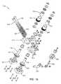
- wire drive assembly 300comprises a fixed block 302 , a movable block 304 , a first drive shaft roller 306 connected to a spur gear 308 via an axle 310 passing through fixed block 302 and a one way clutch 312 , and a second drive shaft roller 314 connected to a spur gear 316 via an axle 318 and a one way clutch 320 .
- a pair of capture blocks 322 and 324rotatably capture drive shaft rollers 306 and 314 to blocks 302 and 304 , respectively.
- Movable block 304is slidably mounted to fixed block 302 via a pair of rods 326 and 328 that pass through movable block 304 , fixed block 302 and are secured to a cam follower 330 , with springs 332 and 334 biasing movable block 304 into engagement with fixed block 302 .
- a lever 336 and cam 338are provided for manually forcing movable block 304 away from fixed block 302 , and hence drive shaft roller 314 away from drive shaft roller 306 , and hence spur gear 316 away from spur gear 308 .
- Wire drive assembly 300is normally disposed in handle assembly 100 so that spur gear 308 and 316 engage the teeth 118 of rack 114 , and so that drive shaft roller 314 is in substantial engagement with drive shaft roller 306 .
- depressing lever 336will cause cam follower 338 to pivot, whereby to force movable block 304 away from fixed block 302 and whereby to separate roller 314 from roller 306 (and to separate spur gear 316 from spur gear 308 ).
- Wire supply cartridge 400may then be inserted between rollers 314 and 306 and, by then restoring lever 336 to its inboard position, cause the suture wire to be gripped by rollers 306 and 314 , whereupon the suture wire may be driven by rollers 306 and 314 out the distal end of the suturing instrument.
- suture wiremay be driven out the distal end of the instrument by depressing lever 104 toward handle 102 .
- Depressing lever 104 toward handle 102causes roll pin 112 (FIG. 2) to ride within slot 110 . More particularly, as the top end of lever 104 moves about pivot pin 108 , roll pin 112 moves through slot 110 .
- Thiscauses rack 114 to move distally, which in turn causes spur gears 308 and 316 to rotate, which in turn causes rollers 306 and 314 to rotate, which in turn causes a length of suture wire to be advanced out the distal end of the suturing instrument.
- lever 104will then cause the cutting bar's pusher element 260 (FIG. 2) to be engaged, whereby cutting bar 246 will sever the formed loop of suture wire from the suture wire remaining in the instrument, lift the trailing end of the suture loop and then push the suture loop free from the suturing instrument.
- lever 104is released, thereby allowing the aforementioned parts to return to their starting position under the influence of spring 116 .
- clutches 312 and 320(FIG. 19) interposed between drive rollers 306 and 314 , and the drive rollers 306 and 314 , respectively, prevent reverse movement of the drive rollers, thereby preventing any retraction of the suture wire.
- a single throw of lever 104will result in a pre-determined degree of movement of drive rollers 306 and 314 , which will in turn result in a pre-determined length of suture wire being advanced out of the distal end of the suturing instrument.
- each drive roller and axle assemblyi.e., drive roller 306 and axle 310 , and drive roller 314 and axle 318
- each drive roller and axle assemblyis preferably machined (i.e., turned) from a single, continuous piece of metal, using the same tool setup, so that the alignment of both is immune from the inaccuracies which might occur if they were turned at different occasions and assembled using holes and holding means.
- This constructionis important, because the drive rollers are approximately 30 times the diameter of the suture wire they are driving and even the slightest alignment inaccuracies can rotate the wire as it is moved forward.
- any such wire rotationmay cause the wire to swerve from its normal trajectory from the end effector and possibly prevent the leading tip of the wire from properly returning to the end effector after it has passed through the subject.
- peripheral groovesmay be formed in drive rollers 306 and 314 . Such grooves provide a seat for the suture wire being driven and help increase the surface area contact between the drive rollers and the suture wire.
- wire supply cartridge 400generally comprises a spool housing 402 , a wire spool 404 , a spool retainer spring 406 , a spool cover 408 , a molded tube support 410 and a wire support tube 412 .
- a length of suture wire 416extends from spool 404 and through molded tube support 410 and wire support tube 412 .
- a supply coil of suture wire 416(comprising wire formed of metal or any other suitable material having the required flexibility and stiffness) may be supplied in the base of cartridge 400 and is fed into wire support tube 412 .
- Wire support tube 412surrounds suture wire 416 from spool housing 402 to the distal end of suturing instrument 2 where, with the distal end of wire support tube 412 received in channel 226 (FIG. 12 ), the suture wire enters second channel 228 in end effector 204 .
- Wire support tube 412ensures that suture wire 416 does not bend or buckle as the suture wire is pushed through handle assembly 100 and cannula assembly 200 .
- wire support tube 412preferably forms a sufficiently close sliding fit with suture wire 416 such that suture wire 416 cannot bend or buckle as the suture wire is advanced through suturing instrument 2 .
- wire support tube 412is also formed so as to present a minimum of friction to suture wire 416 as the suture wire is advanced through the instrument. The foregoing characteristics are important, inasmuch as suture wire 416 is extremely thin and flexible and highly susceptible to bending or buckling in the absence of some sort of lateral support.
- wire support tube 412might have an inside diameter of 0.185 inch and an outside diameter of 0.050 inch.
- wire support tube 412is preferably formed out of 316 stainless steel, however, it may alternatively be formed out of some other material. If desired, the interior of wire support tube 412 may be coated with a lubricant so as to facilitate closely-supported, low friction passage of the suture wire through the wire support tube.
- Wire support tube 412 and its surrounding molded tube support 410have aligned openings 418 and 420 , respectively, on opposite sides thereof. Openings 418 and 420 expose diametrically opposed portions of the suture wire 416 so that rollers 306 and 314 may contact suture wire 416 and urge the suture wire forward toward the distal end of suturing instrument 2 , as will hereinafter be discussed in further detail.
- wire supply cartridge 400may be loaded into wire drive assembly 300 by actuating lever 336 so as to force movable block 304 away from fixed block 302 and thereby separate rollers 306 and 314 .
- roller 314is separated from roller 306 by a sufficient distance, wire support tube 412 may be inserted between rollers 306 and 314 , and then roller 314 returned towards roller 306 such that rollers 306 and 314 contact either side of suture wire 416 through the aligned openings 418 and 420 formed in either side of wire support tube 412 and its surrounding molded support tube 410 , respectively.
- Suturing instrument 2may be used to apply loops 422 (FIG. 26) of wire suture 416 to a subject so as to effect a desired suturing operation.
- suturing instrument 2may be used to suture together two portions 500 , 502 of a subject which is to be sutured.
- portions 500 , 502might comprise two sections of severed tissue which need to be re-attached to one another, or two pieces of previously unattached tissue which need to be attached to one another.
- one or the other of the portions 500 , 502might also comprise artificial mesh or some other object which is to be attached to tissue, etc.
- portions 500 , 502might be located relatively deep within a patient, and might be accessed during an endoscopic or a so-called “minimally invasive” or a so-called “closed surgery”, procedure; however, in other circumstances, portions 500 , 502 might be accessed during a conventional, or so-called “open surgery”, procedure. This latter situation might include procedures done at the outer surface of the patient's body, i.e., where portions 500 , 502 comprise surface elements.
- suturing instrument 2is initially prepared for use by installing a wire supply cartridge 400 into the suturing instrument, if a cartridge 400 is not yet installed.
- wire supply cartridge 400is installed in suturing instrument 2 by (1) removing shroud 126 , (2) moving the wire drive assembly's release lever 336 to its open position, so as to move rollers 306 and 314 apart; (3) passing the distal end of the cartridge (i.e., the distal end of wire support tube 412 ) through wire drive assembly 300 and cannula assembly 200 until the distal end of wire support tube 412 is located in the end effector's first channel 226 , at which point the cartridge's molded tube support 410 will be positioned intermediate rollers 306 and 314 ; and (4) moving the wire drive assembly's release lever 336 back to its closed position, so that rollers 306 and 314 engage the suture wire 416 through openings 420 and 418 , and so that spur gears 308 and 316 engage the teeth 118 of rack 114
- suturing instrument 2When suturing instrument 2 is to apply a suture loop 422 to a subject, the distal end of the suturing instrument is positioned against the subject, e.g., it is positioned against portions 500 , 502 (FIGS. 26 and 27.
- lever 104is pulled back against handle 102 .
- rack 114is also moved distally, whereby rack teeth 118 will cause spur gears 308 and 316 , and hence rollers 306 and 314 , to rotate.
- Rotation of rollers 306 and 314in turn causes suture wire 416 to advance out of the distal end of wire support tube 412 (FIG. 27 ).
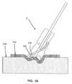
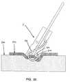
- the suture wireadvances down second channel 228 , across cutter bar channel 232 (FIG. 28 ), through second channel 230 and then out of the instrument (FIG. 29 ).
- the suture wire emerging from end effector 204will take on a set, causing it to curl in a loop fashion, whereby the suture wire will pass through the material to be sutured and then back into slot 264 in the end effector's fixed second portion 224 (FIG. 30 ).
- the guide surface 244may be provided at the distal end of end effector 204 .
- the proximal end 276 (FIG. 17) of slot 264 in the end effector's fixed second portion 224can act as a sort of deflecting anvil to receive and redirect the suture wire 416 received from third channel 230 .
- slot 264actually helps form loop 422 .
- it is not necessary for slot 264 to act as a deflecting anvil for suture wire 416since the curvature of loop 422 can be imparted solely by the geometry of third channel 230 if desired.
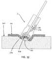
- Suture wire 416is advanced a predetermined amount, i.e., the correct amount to form the desired loop construct.
- a “Q-form loop” 422is to be formed
- suture wire 416is advanced so that the leading end 424 (FIG. 30) of the suture wire passes across cutting bar passageway 232 (FIG. 31) and back out of the instrument until the leading end 424 of the suture wire is intermediate the front end of the tool (FIG. 32 ). At this point the advancement of suture wire 416 is stopped.
- the length of suture wire advanced out of the distal end of the instrumentis regulated by the length of the teeth 118 placed on rack 114 . More particularly, the initial movement of lever 104 toward handle 102 causes the toothed portion 118 of rack 114 to move past spur gears 308 and 316 , whereby to rotate drive rollers 306 and 314 and hence advance suture wire 416 . Further movement of lever 104 toward handle 102 causes the smooth wall 120 of rack 114 to move past spur gears 308 and 316 , which results in no movement of spur gears 308 and 316 and hence no advancement of suture wire 416 . Thus, the length of toothed portion 118 of rack 114 regulates the extent of suture wire drive.
- lever 104continues movement of lever 104 toward handle 102 causes the distal end of the lever to engage the proximal end 260 of the cutting bar 246 , whereby to drive the cutting bar distally (FIG. 32 ).
- Thiscauses the cutting bar 246 to (i) first encounter, and then sever, the proximalmost portion 426 of the suture wire extending across cutting bar passageway 232 , whereby to separate loop 422 from the remainder of the suture wire carried by the suturing tool, and (ii) then drive against the end 426 of loop 422 whereby, with the assistance of island 236 , to bend the end 426 toward the material being joined.
- cutting bar 246includes ejection ramp face 254 and ejection push face 258 at the distal end thereof, and inasmuch as the end effector's fixed second portion 224 includes the slot 264 to form a gap in the end of the end effector, distal movement of cutting bar 246 will also serve to lift loop 422 up over island 236 and push it free from the suturing instrument, whereby to disengage the formed loop 422 from the distal end of suturing instrument 2 .
- cutting bar channel 232may be offset from the plane of wire channels 228 and 232 so as to further assist lifting loop 422 up over island 236 .
- island 236may be formed so as to be mechanically retractable into the body of fixed first portion 222 , whereby to further facilitate disengagement of the formed loop 422 from the suturing instrument.
- wire-related factorse.g., the curvature of third channel 230 , etc.
- wire-related factorse.g., wire tensile strength, wire yield stress, wire diameter, etc.
- tissue-related factorse.g., tissue density, tissue elasticity, tissue thickness, tissue stabilization, etc.
- the aforementioned factorsare preferably taken into account when forming wire loops in tissue.
- a relatively “soft” wirewhen forming a loop in intestine, which tends to be a relatively delicate tissue, it is generally preferable to use a relatively “soft” wire; correspondingly, when forming a loop in the abdominal wall, which tends to be a relatively tough tissue, it is generally preferable to use a relatively “hard” wire
- suture wire formed out of 316 LVM stainless steelhaving a tensile strength of 230-260 kpsi and a diameter of about 0.006-0.019 inch, is advantageous in particular applications.
- suture loopswith a diameter of about 0.140-0.165 inch, it has been found acceptable to provide third channel 230 with a radius of 0.050-0.075 inch.
- suture loop 422can, if desired, have a diameter which exceeds the diameter of suturing instrument.
- cannula assembly 200can be dismounted from handle assembly 100 , a set of different cannula assemblies, each having different loop-forming characteristics, can be provided to the user for appropriate selection at the time of use.
- wire supply cartridge 400can be dismounted from suturing instrument 2 , a set of different wire supply cartridges, each having different suture wire characteristics (e.g., material, hardness, diameter, etc.) can be provided to the user for appropriate selection at the time of use.
- suture wire characteristicse.g., material, hardness, diameter, etc.
- loop 422can be used to secure mesh 502 to tissue 500 , or to attach other objects to tissue, or to attach objects other than tissue together, etc.
- end effector 204is provided with stabilizing projections 272 , 274 (FIGS. 12 and 17 )
- projections 272 , 274are preferably formed narrow enough and long enough to extend completely through the mesh and contact the underlying tissue.
- suturing instrument 2is shown securing one layer of material 502 to an underlying layer of material 500 .
- other types of attachmentsmay also be formed with suture loop 422 .
- FIG. 34two portions 500 , 502 are shown being secured to one another in a so-called “end to end” configuration.
- channels 228 and 230are positioned on opposing sides of cutting bar channel 232 , whereby a length of suture wire 416 , extending between channels 228 and 230 , may be severed by cutting bar 246 .
- the angle at which cutting bar channel 232 intersects channel 228has a bearing on the angle imparted to the leading tip 424 of suture wire 416 . More particularly, in FIG. 35 it will be seen that cutting. bar channel 232 intersects second channel 228 at the angle ⁇ ; as a result, the leading tip of suture wire 416 will also be set at the angle ⁇ .
- the angle ⁇be as small as possible, in order that the suture wire have the sharpest possible tip to facilitate tissue penetration.
- the leading tip of suture wire 416must traverse the substantial curvature of third channel 230 and, if the angle ⁇ is too small, the sharp leading tip of the suture wire will strike the wall of third channel 230 (FIG. 36) and thereby become damaged and/or blunted.
- the angle ⁇is increased, the heel of the tip will engage the wall of third channel 230 (FIG. 37 ), thereby leaving the sharp tip of the suture wire undamaged.
- the angle ⁇be set so that the leading tip of suture wire 416 be formed as sharp as possible while still being able to traverse the curvature of third channel 230 without damage.
- suture loop 422can be used to secure tissue to tissue, or to secure an inanimate object to tissue, or to secure an inanimate object to an inanimate object, etc.
- one anticipated application for suture loop 422is to secure a prosthetic cardiac valve to a valve seat within the heart. See, for example, FIG. 38, where suturing instrument 2 is shown securing a prosthetic cardiac valve 504 to vascular tissue 508 (in this respect it should be appreciated that in FIG. 38, a portion of the vascular tissue 508 has been removed so as to illustrate how suture loops 422 penetrate a portion of cardiac valve 504 ).
- suture wire 416is described as comprising an elongated length which is cut into specific lengths at the time of use by the action of cutting bar 246 .
- suture wire 416may be pre-cut into selected lengths prior to use, and the pre-cut lengths then stored in a magazine or the like, for deployment at the time of use.
- cutting bar 246will act as a forming and ejecting tool rather than as a cutting, forming and ejecting tool.
- suture wire 416may comprise a wire formed out of a metal or any other suitable material having the required flexibility and stiffness.
- suture wire 416may comprise stainless steel, titanium, tantalum, etc.
- suture wire 416may also be coated with various active agents.
- suture wire 416may be coated with an anti-inflammatory agent, or an anti-coagulant agent, or an antibiotic, or a radioactive agent, etc.
- shaft 202has been shown as being substantially straight; however, it is also anticipated that shaft 202 may be curved along its length. Furthermore, shaft 202 may be substantially rigid, or it may be flexible so that it can be bent along its length. It is also possible to form shaft 202 so that it has two or more articulating sections so as to aid in the positioning of end effector 204 .
Landscapes
- Health & Medical Sciences (AREA)
- Life Sciences & Earth Sciences (AREA)
- Surgery (AREA)
- Heart & Thoracic Surgery (AREA)
- Engineering & Computer Science (AREA)
- Biomedical Technology (AREA)
- Nuclear Medicine, Radiotherapy & Molecular Imaging (AREA)
- Medical Informatics (AREA)
- Molecular Biology (AREA)
- Animal Behavior & Ethology (AREA)
- General Health & Medical Sciences (AREA)
- Public Health (AREA)
- Veterinary Medicine (AREA)
- Surgical Instruments (AREA)
Abstract
Description
Claims (42)
Priority Applications (3)
| Application Number | Priority Date | Filing Date | Title |
|---|---|---|---|
| US10/082,510US6511489B2 (en) | 1999-08-03 | 2001-10-19 | Surgical suturing instrument and method of use |
| US10/352,600US7666194B2 (en) | 2000-10-20 | 2003-01-28 | Surgical suturing instrument and method of use |
| US11/436,388US20060282101A1 (en) | 2000-03-27 | 2006-05-18 | Surgical suturing instrument and method for use |
Applications Claiming Priority (6)
| Application Number | Priority Date | Filing Date | Title |
|---|---|---|---|
| US09/368,273US6332889B1 (en) | 1998-08-27 | 1999-08-03 | Surgical suturing instrument and method of use |
| US19248700P | 2000-03-27 | 2000-03-27 | |
| US24193600P | 2000-10-20 | 2000-10-20 | |
| US24226900P | 2000-10-20 | 2000-10-20 | |
| US09/818,300US6527785B2 (en) | 1999-08-03 | 2001-03-27 | Surgical suturing instrument and method of use |
| US10/082,510US6511489B2 (en) | 1999-08-03 | 2001-10-19 | Surgical suturing instrument and method of use |
Related Parent Applications (1)
| Application Number | Title | Priority Date | Filing Date |
|---|---|---|---|
| US09/818,300Continuation-In-PartUS6527785B2 (en) | 1999-08-03 | 2001-03-27 | Surgical suturing instrument and method of use |
Related Child Applications (1)
| Application Number | Title | Priority Date | Filing Date |
|---|---|---|---|
| US10/352,600ContinuationUS7666194B2 (en) | 2000-03-27 | 2003-01-28 | Surgical suturing instrument and method of use |
Publications (2)
| Publication Number | Publication Date |
|---|---|
| US20020128669A1 US20020128669A1 (en) | 2002-09-12 |
| US6511489B2true US6511489B2 (en) | 2003-01-28 |
Family
ID=27539285
Family Applications (1)
| Application Number | Title | Priority Date | Filing Date |
|---|---|---|---|
| US10/082,510Expired - LifetimeUS6511489B2 (en) | 1999-08-03 | 2001-10-19 | Surgical suturing instrument and method of use |
Country Status (1)
| Country | Link |
|---|---|
| US (1) | US6511489B2 (en) |
Cited By (51)
| Publication number | Priority date | Publication date | Assignee | Title |
|---|---|---|---|---|
| US20020123756A1 (en)* | 1996-10-21 | 2002-09-05 | Sauer Jude S. | Vascular hole closure |
| US20020128666A1 (en)* | 1998-08-27 | 2002-09-12 | Sancoff Gregory E. | Surgical suturing instrument and method of use |
| US20030105476A1 (en)* | 2001-09-14 | 2003-06-05 | Sancoff Gregory E. | Surgical suturing instrument and method of use |
| US20030105475A1 (en)* | 2001-07-23 | 2003-06-05 | Sancoff Gregory E. | Surgical suturing instrument and method of use |
| US20030171761A1 (en)* | 1999-08-03 | 2003-09-11 | Sancoff Gregory E. | Surgical suturing instrument and method of use |
| US6641592B1 (en)* | 1999-11-19 | 2003-11-04 | Lsi Solutions, Inc. | System for wound closure |
| US20030236534A1 (en)* | 2002-04-17 | 2003-12-25 | Helmut Kayan | Tacking tool and tack |
| US20040087979A1 (en)* | 2002-03-25 | 2004-05-06 | Field Frederic P. | Surgical suturing instrument and method of use |
| US20040092967A1 (en)* | 2001-12-11 | 2004-05-13 | Sancoff Gregory E. | Surgical suturing instrument and method of use |
| US20040122449A1 (en)* | 1999-03-04 | 2004-06-24 | Modesitt D. Bruce | Articulating suturing device and method |
| US20040172047A1 (en)* | 2001-08-24 | 2004-09-02 | Scimed Life Systems, Inc. | Forward deploying suturing device and methods of use |
| US20040186487A1 (en)* | 1992-12-10 | 2004-09-23 | Klein Enrique J. | Device and method for suturing tissue |
| US20040254592A1 (en)* | 2002-05-17 | 2004-12-16 | Dicarlo Joseph A. | Surgical suturing instrument and method of use |
| US20050015101A1 (en)* | 2001-10-04 | 2005-01-20 | Gibbens George H. | Leverage locking reversible cyclic suturing and knot-tying device |
| US20050038449A1 (en)* | 1999-11-05 | 2005-02-17 | Sancoff Gregory E. | Apparatus and method for placing suture wires into tissue for the approximation and tensioning of tissue |
| US20050059982A1 (en)* | 2003-09-11 | 2005-03-17 | Michael Zung | Articulating suturing device and method |
| US20050101990A1 (en)* | 2002-08-19 | 2005-05-12 | Aragon Steven B. | Wire dispenser for use with forceps |
| US20060025790A1 (en)* | 2003-12-23 | 2006-02-02 | Umc Utrecht Holding B.V. | Operation element, operation set and method for use thereof |
| US20060142785A1 (en)* | 1999-03-04 | 2006-06-29 | Modesitt D B | Articulating suturing device and method |
| US20060173469A1 (en)* | 2001-01-24 | 2006-08-03 | Klein Enrique J | Device and method for suturing of internal puncture sites |
| US7131980B1 (en) | 2001-01-18 | 2006-11-07 | Dvl Acquisitions Sub, Inc. | Surgical suturing instrument and method of use |
| US20070032799A1 (en)* | 2005-08-08 | 2007-02-08 | Pantages Anthony J | Vascular suturing device |
| US20070049968A1 (en)* | 2005-08-24 | 2007-03-01 | Sibbitt Wilmer L Jr | Vascular opening edge eversion methods and apparatuses |
| US20070112304A1 (en)* | 2002-12-31 | 2007-05-17 | Abbott Laboratories | Systems for anchoring a medical device in a body lumen |
| US20070167959A1 (en)* | 1999-03-04 | 2007-07-19 | Abbott Laboratories | Articulating suturing device and method |
| US20070276410A1 (en)* | 2003-09-26 | 2007-11-29 | Abbott Laboratories | Device for suturing intracardiac defects |
| US20080300624A1 (en)* | 2007-05-30 | 2008-12-04 | Ethicon Endo-Surgery, Inc. | Tissue Stabilizer and Fastener |
| US20080306586A1 (en)* | 2007-02-05 | 2008-12-11 | Cartledge Richard G | Minimally Invasive System for Delivering and Securing an Annular Implant |
| US20080319458A1 (en)* | 2007-06-25 | 2008-12-25 | Abbott Laboratories | System for closing a puncture in a vessel wall |
| US7666194B2 (en) | 2000-10-20 | 2010-02-23 | Onux Medical, Inc. | Surgical suturing instrument and method of use |
| US20100241142A1 (en)* | 2009-03-23 | 2010-09-23 | Linvatec Corporation | Suture passing apparatus and method |
| US7842048B2 (en) | 2006-08-18 | 2010-11-30 | Abbott Laboratories | Articulating suture device and method |
| US20100327042A1 (en)* | 2008-03-14 | 2010-12-30 | Amid Parviz K | Hernia stapler with integrated mesh manipulator |
| US8038688B2 (en) | 1999-03-04 | 2011-10-18 | Abbott Laboratories | Articulating suturing device and method |
| US8048108B2 (en) | 2005-08-24 | 2011-11-01 | Abbott Vascular Inc. | Vascular closure methods and apparatuses |
| US8083754B2 (en) | 2005-08-08 | 2011-12-27 | Abbott Laboratories | Vascular suturing device with needle capture |
| US8105355B2 (en) | 2006-05-18 | 2012-01-31 | C.R. Bard, Inc. | Suture lock fastening device |
| US8267947B2 (en) | 2005-08-08 | 2012-09-18 | Abbott Laboratories | Vascular suturing device |
| US8419753B2 (en) | 2003-12-23 | 2013-04-16 | Abbott Laboratories | Suturing device with split arm and method of suturing tissue |
| US20130184720A1 (en)* | 2012-01-13 | 2013-07-18 | Dallen Medical, Inc. | Actuator for band tensioning system |
| US8663252B2 (en) | 2010-09-01 | 2014-03-04 | Abbott Cardiovascular Systems, Inc. | Suturing devices and methods |
| US8758370B2 (en) | 2001-10-22 | 2014-06-24 | Interventional Therapies, Llc | Suture loading assembly |
| US8858573B2 (en) | 2012-04-10 | 2014-10-14 | Abbott Cardiovascular Systems, Inc. | Apparatus and method for suturing body lumens |
| US8864778B2 (en) | 2012-04-10 | 2014-10-21 | Abbott Cardiovascular Systems, Inc. | Apparatus and method for suturing body lumens |
| US8870049B2 (en) | 2008-03-14 | 2014-10-28 | Transenterix, Inc. | Hernia stapler |
| US9241707B2 (en) | 2012-05-31 | 2016-01-26 | Abbott Cardiovascular Systems, Inc. | Systems, methods, and devices for closing holes in body lumens |
| US9370353B2 (en) | 2010-09-01 | 2016-06-21 | Abbott Cardiovascular Systems, Inc. | Suturing devices and methods |
| US9456811B2 (en) | 2005-08-24 | 2016-10-04 | Abbott Vascular Inc. | Vascular closure methods and apparatuses |
| US20180085114A1 (en)* | 2006-01-27 | 2018-03-29 | Endoevolution, Llc | Apparatus and method for tissue closure |
| US10258322B2 (en) | 2013-04-17 | 2019-04-16 | Maruho Medical, Inc. | Method and apparatus for passing suture |
| US10426449B2 (en) | 2017-02-16 | 2019-10-01 | Abbott Cardiovascular Systems, Inc. | Articulating suturing device with improved actuation and alignment mechanisms |
Families Citing this family (3)
| Publication number | Priority date | Publication date | Assignee | Title |
|---|---|---|---|---|
| JP2006509595A (en)* | 2002-12-16 | 2006-03-23 | エドリッチ・ヴァスキュラー・ディヴァイシズ,インコーポレイテッド | Multiple stapling instruments for narrow vessels |
| US10918381B2 (en) | 2016-12-07 | 2021-02-16 | Ethicon, Inc. | Applicator instruments having drive systems with flexible members for dispensing surgical fasteners |
| CN116236242B (en)* | 2021-12-07 | 2025-07-01 | 苏州微创骨科医疗工具有限公司 | Wire cutters |
Citations (89)
| Publication number | Priority date | Publication date | Assignee | Title |
|---|---|---|---|---|
| US2613562A (en)* | 1947-05-27 | 1952-10-14 | John W Clark | Watch hand pressing tool |
| US2897820A (en)* | 1956-10-23 | 1959-08-04 | Tauber Robert | Surgical needle guiding instrument |
| US3404677A (en)* | 1965-07-08 | 1968-10-08 | Henry A. Springer | Biopsy and tissue removing device |
| US3470875A (en)* | 1966-10-06 | 1969-10-07 | Alfred A Johnson | Surgical clamping and suturing instrument |
| US3584628A (en)* | 1968-10-11 | 1971-06-15 | United States Surgical Corp | Wire suture wrapping instrument |
| US3802438A (en)* | 1972-03-31 | 1974-04-09 | Technibiotics | Surgical instrument |
| US3807407A (en)* | 1971-06-07 | 1974-04-30 | E Schweizer | Suture applicator |
| US3841521A (en)* | 1970-08-17 | 1974-10-15 | R Jarvik | Repeating ligature guns, multi-ligature cartridges and preformed ligatures therefor |
| US3858783A (en)* | 1972-11-20 | 1975-01-07 | Nikolai Nikolaevich Kapitanov | Surgical instrument for stitching up tissues with lengths of suture wire |
| US3877570A (en)* | 1973-07-25 | 1975-04-15 | Robert J Barry | Sterile cosmetic suture for attaching hair pieces to scalp and method of packaging and utilizing |
| US3959960A (en)* | 1975-03-12 | 1976-06-01 | Santos Manuel V | Tensioning, twisting and cutting device for sutures |
| US4006747A (en)* | 1975-04-23 | 1977-02-08 | Ethicon, Inc. | Surgical method |
| US4027608A (en)* | 1976-02-20 | 1977-06-07 | Raymond Kelder | Suturing device |
| US4103690A (en)* | 1977-03-21 | 1978-08-01 | Cordis Corporation | Self-suturing cardiac pacer lead |
| US4109658A (en)* | 1977-02-04 | 1978-08-29 | Hughes Joe L | Needle holding device with pick-up means |
| US4204541A (en)* | 1977-01-24 | 1980-05-27 | Kapitanov Nikolai N | Surgical instrument for stitching up soft tissues with lengths of spiked suture material |
| US4235177A (en)* | 1979-02-23 | 1980-11-25 | Raymond C. Kelder | Suturing device |
| US4258716A (en)* | 1978-02-06 | 1981-03-31 | The University Of Melbourne | Microsurgical instruments |
| US4306560A (en)* | 1978-07-10 | 1981-12-22 | Cordis Corporation | Suture forming tool for securing an electrode to generally inaccessible body tissue |
| US4453661A (en)* | 1980-10-23 | 1984-06-12 | Ivano-Frankovsky Gosudarstvenny Meditsinsky Institut | Surgical instrument for applying staples |
| US4462404A (en)* | 1981-01-31 | 1984-07-31 | Vormals Jetter & Scheerer Aesculap-Werke Aktiengesellschaft | Forceps- or tweezers-shaped surgical instrument |
| US4474181A (en)* | 1982-02-18 | 1984-10-02 | Schenck Robert R | Method and apparatus for anastomosing small blood vessels |
| US4553543A (en)* | 1984-03-05 | 1985-11-19 | Amarasinghe Disamodha C | Suturing assembly and method |
| US4557265A (en)* | 1983-02-08 | 1985-12-10 | Innova Ab | Suturing instrument |
| US4583541A (en)* | 1984-05-07 | 1986-04-22 | Barry Joseph P | Sternal stabilization device |
| US4602636A (en)* | 1983-03-08 | 1986-07-29 | Joint Medical Products Corporation | Suture wire with integral needle-like tip |
| US4607637A (en)* | 1983-07-22 | 1986-08-26 | Anders Berggren | Surgical instrument for performing anastomosis with the aid of ring-like fastening elements and the fastening elements for performing anastomosis |
| US4624257A (en)* | 1982-06-24 | 1986-11-25 | Anders Berggren | Surgical instrument for performing anastomosis |
| US4643190A (en)* | 1984-06-23 | 1987-02-17 | Richard Wolf Gmbh | Medical forceps |
| US4644651A (en)* | 1984-03-19 | 1987-02-24 | Jacobsen Research Corp. | Instrument for gripping or cutting |
| US4747358A (en)* | 1986-01-30 | 1988-05-31 | G.M.Pfaff Aktiengesellschaft | Surgical suturing machine |
| US4760848A (en)* | 1986-11-03 | 1988-08-02 | Hasson Harrith M | Rotational surgical instrument |
| US4763669A (en)* | 1986-01-09 | 1988-08-16 | Jaeger John C | Surgical instrument with adjustable angle of operation |
| US4803984A (en)* | 1987-07-06 | 1989-02-14 | Montefiore Hospital Association Of Western Pennsylvania | Method for performing small vessel anastomosis |
| US4819635A (en)* | 1987-09-18 | 1989-04-11 | Henry Shapiro | Tubular microsurgery cutting apparatus |
| US4890615A (en)* | 1987-11-05 | 1990-01-02 | Concept, Inc. | Arthroscopic suturing instrument |
| US4901721A (en)* | 1988-08-02 | 1990-02-20 | Hakki Samir I | Suturing device |
| US4915107A (en)* | 1988-03-09 | 1990-04-10 | Harley International Medical Ltd. | Automatic instrument for purse-string sutures for surgical use |
| US4935027A (en)* | 1989-08-21 | 1990-06-19 | Inbae Yoon | Surgical suture instrument with remotely controllable suture material advancement |
| US4938214A (en)* | 1984-09-10 | 1990-07-03 | Micrins Surgical Instruments, Ltd. | Hand held surgical tool |
| US4941466A (en)* | 1987-04-13 | 1990-07-17 | Romano Jack W | Curved bore drilling method and apparatus |
| US4955887A (en)* | 1988-05-11 | 1990-09-11 | Storz Instrument Company | Optical surgical instrument |
| US4957498A (en)* | 1987-11-05 | 1990-09-18 | Concept, Inc. | Suturing instrument |
| US5002564A (en)* | 1989-06-19 | 1991-03-26 | Ethicon, Inc. | Surgical needle configuration with spatula geometry |
| US5004469A (en)* | 1989-03-07 | 1991-04-02 | Ricerche Biomediche S.R.L. | Improvements in automatic mechanical suturing guns |
| US5133735A (en)* | 1990-05-10 | 1992-07-28 | Symbiosis Corporation | Thumb-activated actuating member for imparting reciprocal motion to push rod of a disposable laparoscopic surgical instrument |
| US5174300A (en)* | 1991-04-04 | 1992-12-29 | Symbiosis Corporation | Endoscopic surgical instruments having rotatable end effectors |
| US5192298A (en)* | 1990-05-10 | 1993-03-09 | Symbiosis Corporation | Disposable laparoscopic surgical instruments |
| US5217465A (en)* | 1992-02-28 | 1993-06-08 | Alcon Surgical, Inc. | Flexible and steerable aspiration tip for microsurgery |
| US5219357A (en)* | 1990-05-31 | 1993-06-15 | Tnco, Inc. | Micro-instrument |
| US5234453A (en)* | 1990-05-10 | 1993-08-10 | Symblosis Corporation | Cobalt base alloy end effectors for laparoscopic surgical scissors |
| US5242459A (en)* | 1992-07-10 | 1993-09-07 | Laparomed Corporation | Device and method for applying a ligating loop |
| US5261917A (en)* | 1992-02-19 | 1993-11-16 | Hasson Harrith M | Suture tying forceps with a plurality of suture holders and method of tying a suture |
| US5290284A (en)* | 1992-05-01 | 1994-03-01 | Adair Edwin Lloyd | Laparoscopic surgical ligation and electrosurgical coagulation and cutting device |
| US5304183A (en)* | 1992-03-23 | 1994-04-19 | Laparomed Corporation | Tethered clamp retractor |
| US5306281A (en)* | 1992-08-31 | 1994-04-26 | Merrimac Industries, Inc. | Suturing cassette device |
| US5308357A (en)* | 1992-08-21 | 1994-05-03 | Microsurge, Inc. | Handle mechanism for manual instruments |
| US5308353A (en)* | 1992-08-31 | 1994-05-03 | Merrimac Industries, Inc. | Surgical suturing device |
| US5324308A (en)* | 1993-10-28 | 1994-06-28 | Javin Pierce | Suture anchor |
| US5333625A (en)* | 1988-08-18 | 1994-08-02 | Rikki Brezak | Suturing with corrosion and breakage resistant flexible wire |
| US5356424A (en)* | 1993-02-05 | 1994-10-18 | American Cyanamid Co. | Laparoscopic suturing device |
| US5370658A (en)* | 1992-11-05 | 1994-12-06 | Synergetics, Inc. | Microsurgical instrument having dexterous handle with interchangeable instrument heads |
| US5372604A (en)* | 1993-06-18 | 1994-12-13 | Linvatec Corporation | Suture anchor for soft tissue fixation |
| US5386741A (en)* | 1993-06-07 | 1995-02-07 | Rennex; Brian G. | Robotic snake |
| US5411522A (en)* | 1993-08-25 | 1995-05-02 | Linvatec Corporation | Unitary anchor for soft tissue fixation |
| US5417701A (en)* | 1993-03-30 | 1995-05-23 | Holmed Corporation | Surgical instrument with magnetic needle holder |
| US5423821A (en)* | 1994-01-18 | 1995-06-13 | Pasque; Michael K. | Sternal closure device |
| US5431670A (en)* | 1993-10-13 | 1995-07-11 | Hol-Med Corporation | Surgical suturing instrument |
| US5437681A (en)* | 1994-01-13 | 1995-08-01 | Suturtek Inc. | Suturing instrument with thread management |
| US5474554A (en)* | 1994-07-27 | 1995-12-12 | Ku; Ming-Chou | Method for fixation of avulsion fracture |
| US5478093A (en)* | 1993-06-28 | 1995-12-26 | Dentalwerk Burmoos Gesellschaft M.B.H. | Surgical handpiece |
| US5496334A (en)* | 1993-03-31 | 1996-03-05 | J. Stro/ bel & Sohne GmbH & Co. | Suturing apparatus |
| US5498256A (en)* | 1993-05-28 | 1996-03-12 | Snowden-Pencer, Inc. | Surgical instrument handle |
| US5499990A (en)* | 1992-05-23 | 1996-03-19 | Forschungszentrum Karlsruhe Gmbh | Suturing instrument |
| US5501688A (en)* | 1994-02-17 | 1996-03-26 | Surgical Accessories, Inc. | Surgical device for manipulating wire |
| US5501692A (en)* | 1994-01-28 | 1996-03-26 | Riza; Erol D. | Laparoscopic suture snare |
| US5501698A (en)* | 1994-02-14 | 1996-03-26 | Heartport, Inc. | Endoscopic microsurgical instruments and methods |
| US5571119A (en)* | 1993-10-25 | 1996-11-05 | Children's Medical Center Corporation | Retractable suture needle with self-contained driver |
| US5674230A (en)* | 1993-10-08 | 1997-10-07 | United States Surgical Corporation | Surgical suturing apparatus with locking mechanisms |
| US5690653A (en)* | 1991-09-30 | 1997-11-25 | Richardson; Philip | Suturing apparatus |
| US5709693A (en)* | 1996-02-20 | 1998-01-20 | Cardiothoracic System, Inc. | Stitcher |
| US5720766A (en)* | 1994-02-23 | 1998-02-24 | Orthopaedic Biosystems Limited, Inc. | Apparatus for attaching soft tissue to bone |
| US5728112A (en)* | 1995-09-22 | 1998-03-17 | Yoon; Inbae | Combined tissue clamping and suturing instrument |
| US5759188A (en)* | 1996-11-27 | 1998-06-02 | Yoon; Inbae | Suturing instrument with rotatably mounted needle driver and catcher |
| US5766217A (en)* | 1996-09-23 | 1998-06-16 | Christy; William J. | Surgical loop delivery device and method |
| US5766186A (en)* | 1996-12-03 | 1998-06-16 | Simon Fraser University | Suturing device |
| US5799672A (en)* | 1996-07-26 | 1998-09-01 | Hansbury; Barbara J. | Hair retaining device |
| US5814054A (en)* | 1996-09-23 | 1998-09-29 | Symbiosis Corporation | Automatic needle-passer suturing instrument |
| US5830234A (en)* | 1997-04-04 | 1998-11-03 | Alto Development Corporation | Method for double wire sternotomy suture |
- 2001
- 2001-10-19USUS10/082,510patent/US6511489B2/ennot_activeExpired - Lifetime
Patent Citations (96)
| Publication number | Priority date | Publication date | Assignee | Title |
|---|---|---|---|---|
| US2613562A (en)* | 1947-05-27 | 1952-10-14 | John W Clark | Watch hand pressing tool |
| US2897820A (en)* | 1956-10-23 | 1959-08-04 | Tauber Robert | Surgical needle guiding instrument |
| US3404677A (en)* | 1965-07-08 | 1968-10-08 | Henry A. Springer | Biopsy and tissue removing device |
| US3470875A (en)* | 1966-10-06 | 1969-10-07 | Alfred A Johnson | Surgical clamping and suturing instrument |
| US3584628A (en)* | 1968-10-11 | 1971-06-15 | United States Surgical Corp | Wire suture wrapping instrument |
| US3841521A (en)* | 1970-08-17 | 1974-10-15 | R Jarvik | Repeating ligature guns, multi-ligature cartridges and preformed ligatures therefor |
| US3807407A (en)* | 1971-06-07 | 1974-04-30 | E Schweizer | Suture applicator |
| US3802438A (en)* | 1972-03-31 | 1974-04-09 | Technibiotics | Surgical instrument |
| US3858783A (en)* | 1972-11-20 | 1975-01-07 | Nikolai Nikolaevich Kapitanov | Surgical instrument for stitching up tissues with lengths of suture wire |
| US3877570A (en)* | 1973-07-25 | 1975-04-15 | Robert J Barry | Sterile cosmetic suture for attaching hair pieces to scalp and method of packaging and utilizing |
| US3959960A (en)* | 1975-03-12 | 1976-06-01 | Santos Manuel V | Tensioning, twisting and cutting device for sutures |
| US4006747A (en)* | 1975-04-23 | 1977-02-08 | Ethicon, Inc. | Surgical method |
| US4027608A (en)* | 1976-02-20 | 1977-06-07 | Raymond Kelder | Suturing device |
| US4204541A (en)* | 1977-01-24 | 1980-05-27 | Kapitanov Nikolai N | Surgical instrument for stitching up soft tissues with lengths of spiked suture material |
| US4109658A (en)* | 1977-02-04 | 1978-08-29 | Hughes Joe L | Needle holding device with pick-up means |
| US4103690A (en)* | 1977-03-21 | 1978-08-01 | Cordis Corporation | Self-suturing cardiac pacer lead |
| US4258716A (en)* | 1978-02-06 | 1981-03-31 | The University Of Melbourne | Microsurgical instruments |
| US4306560A (en)* | 1978-07-10 | 1981-12-22 | Cordis Corporation | Suture forming tool for securing an electrode to generally inaccessible body tissue |
| US4235177A (en)* | 1979-02-23 | 1980-11-25 | Raymond C. Kelder | Suturing device |
| US4453661A (en)* | 1980-10-23 | 1984-06-12 | Ivano-Frankovsky Gosudarstvenny Meditsinsky Institut | Surgical instrument for applying staples |
| US4462404A (en)* | 1981-01-31 | 1984-07-31 | Vormals Jetter & Scheerer Aesculap-Werke Aktiengesellschaft | Forceps- or tweezers-shaped surgical instrument |
| US4474181A (en)* | 1982-02-18 | 1984-10-02 | Schenck Robert R | Method and apparatus for anastomosing small blood vessels |
| US4624257A (en)* | 1982-06-24 | 1986-11-25 | Anders Berggren | Surgical instrument for performing anastomosis |
| US4557265A (en)* | 1983-02-08 | 1985-12-10 | Innova Ab | Suturing instrument |
| US4602636A (en)* | 1983-03-08 | 1986-07-29 | Joint Medical Products Corporation | Suture wire with integral needle-like tip |
| US4607637A (en)* | 1983-07-22 | 1986-08-26 | Anders Berggren | Surgical instrument for performing anastomosis with the aid of ring-like fastening elements and the fastening elements for performing anastomosis |
| US4553543A (en)* | 1984-03-05 | 1985-11-19 | Amarasinghe Disamodha C | Suturing assembly and method |
| US4644651A (en)* | 1984-03-19 | 1987-02-24 | Jacobsen Research Corp. | Instrument for gripping or cutting |
| US4583541A (en)* | 1984-05-07 | 1986-04-22 | Barry Joseph P | Sternal stabilization device |
| US4643190A (en)* | 1984-06-23 | 1987-02-17 | Richard Wolf Gmbh | Medical forceps |
| US4938214A (en)* | 1984-09-10 | 1990-07-03 | Micrins Surgical Instruments, Ltd. | Hand held surgical tool |
| US4763669A (en)* | 1986-01-09 | 1988-08-16 | Jaeger John C | Surgical instrument with adjustable angle of operation |
| US4747358A (en)* | 1986-01-30 | 1988-05-31 | G.M.Pfaff Aktiengesellschaft | Surgical suturing machine |
| US4760848A (en)* | 1986-11-03 | 1988-08-02 | Hasson Harrith M | Rotational surgical instrument |
| US4941466A (en)* | 1987-04-13 | 1990-07-17 | Romano Jack W | Curved bore drilling method and apparatus |
| US4803984A (en)* | 1987-07-06 | 1989-02-14 | Montefiore Hospital Association Of Western Pennsylvania | Method for performing small vessel anastomosis |
| US4819635A (en)* | 1987-09-18 | 1989-04-11 | Henry Shapiro | Tubular microsurgery cutting apparatus |
| US4957498A (en)* | 1987-11-05 | 1990-09-18 | Concept, Inc. | Suturing instrument |
| US4923461A (en)* | 1987-11-05 | 1990-05-08 | Concept, Inc. | Method of arthroscopic suturing of tissue |
| US4890615B1 (en)* | 1987-11-05 | 1993-11-16 | Linvatec Corporation | Arthroscopic suturing instrument |
| US4923461B2 (en)* | 1987-11-05 | 1995-06-20 | Linvatec Corp | Method of arthroscopic suturing |
| US4890615A (en)* | 1987-11-05 | 1990-01-02 | Concept, Inc. | Arthroscopic suturing instrument |
| US4923461B1 (en)* | 1987-11-05 | 1994-10-18 | Linvatec Corp | Method of arthroscopic suturing of tissue |
| US4915107A (en)* | 1988-03-09 | 1990-04-10 | Harley International Medical Ltd. | Automatic instrument for purse-string sutures for surgical use |
| US4955887A (en)* | 1988-05-11 | 1990-09-11 | Storz Instrument Company | Optical surgical instrument |
| US4901721A (en)* | 1988-08-02 | 1990-02-20 | Hakki Samir I | Suturing device |
| US5333625A (en)* | 1988-08-18 | 1994-08-02 | Rikki Brezak | Suturing with corrosion and breakage resistant flexible wire |
| US5004469A (en)* | 1989-03-07 | 1991-04-02 | Ricerche Biomediche S.R.L. | Improvements in automatic mechanical suturing guns |
| US5002564A (en)* | 1989-06-19 | 1991-03-26 | Ethicon, Inc. | Surgical needle configuration with spatula geometry |
| US4935027A (en)* | 1989-08-21 | 1990-06-19 | Inbae Yoon | Surgical suture instrument with remotely controllable suture material advancement |
| US5234453A (en)* | 1990-05-10 | 1993-08-10 | Symblosis Corporation | Cobalt base alloy end effectors for laparoscopic surgical scissors |
| US5192298A (en)* | 1990-05-10 | 1993-03-09 | Symbiosis Corporation | Disposable laparoscopic surgical instruments |
| US5133735A (en)* | 1990-05-10 | 1992-07-28 | Symbiosis Corporation | Thumb-activated actuating member for imparting reciprocal motion to push rod of a disposable laparoscopic surgical instrument |
| US5219357A (en)* | 1990-05-31 | 1993-06-15 | Tnco, Inc. | Micro-instrument |
| US5174300A (en)* | 1991-04-04 | 1992-12-29 | Symbiosis Corporation | Endoscopic surgical instruments having rotatable end effectors |
| US5690653A (en)* | 1991-09-30 | 1997-11-25 | Richardson; Philip | Suturing apparatus |
| US5261917A (en)* | 1992-02-19 | 1993-11-16 | Hasson Harrith M | Suture tying forceps with a plurality of suture holders and method of tying a suture |
| US5217465A (en)* | 1992-02-28 | 1993-06-08 | Alcon Surgical, Inc. | Flexible and steerable aspiration tip for microsurgery |
| US5304183A (en)* | 1992-03-23 | 1994-04-19 | Laparomed Corporation | Tethered clamp retractor |
| US5290284A (en)* | 1992-05-01 | 1994-03-01 | Adair Edwin Lloyd | Laparoscopic surgical ligation and electrosurgical coagulation and cutting device |
| US5499990A (en)* | 1992-05-23 | 1996-03-19 | Forschungszentrum Karlsruhe Gmbh | Suturing instrument |
| US5242459A (en)* | 1992-07-10 | 1993-09-07 | Laparomed Corporation | Device and method for applying a ligating loop |
| US5308357A (en)* | 1992-08-21 | 1994-05-03 | Microsurge, Inc. | Handle mechanism for manual instruments |
| US5308353A (en)* | 1992-08-31 | 1994-05-03 | Merrimac Industries, Inc. | Surgical suturing device |
| US5306281A (en)* | 1992-08-31 | 1994-04-26 | Merrimac Industries, Inc. | Suturing cassette device |
| US5370658A (en)* | 1992-11-05 | 1994-12-06 | Synergetics, Inc. | Microsurgical instrument having dexterous handle with interchangeable instrument heads |
| US5356424A (en)* | 1993-02-05 | 1994-10-18 | American Cyanamid Co. | Laparoscopic suturing device |
| US5417701A (en)* | 1993-03-30 | 1995-05-23 | Holmed Corporation | Surgical instrument with magnetic needle holder |
| US5496334A (en)* | 1993-03-31 | 1996-03-05 | J. Stro/ bel & Sohne GmbH & Co. | Suturing apparatus |
| US5498256A (en)* | 1993-05-28 | 1996-03-12 | Snowden-Pencer, Inc. | Surgical instrument handle |
| US5386741A (en)* | 1993-06-07 | 1995-02-07 | Rennex; Brian G. | Robotic snake |
| US5372604A (en)* | 1993-06-18 | 1994-12-13 | Linvatec Corporation | Suture anchor for soft tissue fixation |
| US5500001A (en)* | 1993-06-18 | 1996-03-19 | Linvatec Corporation | Suture anchor for soft tissue fixation |
| US5501683A (en)* | 1993-06-18 | 1996-03-26 | Linvatec Corporation | Suture anchor for soft tissue fixation |
| US5478093A (en)* | 1993-06-28 | 1995-12-26 | Dentalwerk Burmoos Gesellschaft M.B.H. | Surgical handpiece |
| US5411522A (en)* | 1993-08-25 | 1995-05-02 | Linvatec Corporation | Unitary anchor for soft tissue fixation |
| US5674230A (en)* | 1993-10-08 | 1997-10-07 | United States Surgical Corporation | Surgical suturing apparatus with locking mechanisms |
| US5431670A (en)* | 1993-10-13 | 1995-07-11 | Hol-Med Corporation | Surgical suturing instrument |
| US5571119A (en)* | 1993-10-25 | 1996-11-05 | Children's Medical Center Corporation | Retractable suture needle with self-contained driver |
| US5324308A (en)* | 1993-10-28 | 1994-06-28 | Javin Pierce | Suture anchor |
| US5437681A (en)* | 1994-01-13 | 1995-08-01 | Suturtek Inc. | Suturing instrument with thread management |
| US5423821A (en)* | 1994-01-18 | 1995-06-13 | Pasque; Michael K. | Sternal closure device |
| US5501692A (en)* | 1994-01-28 | 1996-03-26 | Riza; Erol D. | Laparoscopic suture snare |
| US5618306A (en)* | 1994-02-14 | 1997-04-08 | Heartport, Inc. | Endoscopic microsurgical instruments and methods |
| US5501698A (en)* | 1994-02-14 | 1996-03-26 | Heartport, Inc. | Endoscopic microsurgical instruments and methods |
| US5501688A (en)* | 1994-02-17 | 1996-03-26 | Surgical Accessories, Inc. | Surgical device for manipulating wire |
| US5720766A (en)* | 1994-02-23 | 1998-02-24 | Orthopaedic Biosystems Limited, Inc. | Apparatus for attaching soft tissue to bone |
| US5474554A (en)* | 1994-07-27 | 1995-12-12 | Ku; Ming-Chou | Method for fixation of avulsion fracture |
| US5728112A (en)* | 1995-09-22 | 1998-03-17 | Yoon; Inbae | Combined tissue clamping and suturing instrument |
| US5709693A (en)* | 1996-02-20 | 1998-01-20 | Cardiothoracic System, Inc. | Stitcher |
| US5799672A (en)* | 1996-07-26 | 1998-09-01 | Hansbury; Barbara J. | Hair retaining device |
| US5766217A (en)* | 1996-09-23 | 1998-06-16 | Christy; William J. | Surgical loop delivery device and method |
| US5814054A (en)* | 1996-09-23 | 1998-09-29 | Symbiosis Corporation | Automatic needle-passer suturing instrument |
| US5759188A (en)* | 1996-11-27 | 1998-06-02 | Yoon; Inbae | Suturing instrument with rotatably mounted needle driver and catcher |
| US5766186A (en)* | 1996-12-03 | 1998-06-16 | Simon Fraser University | Suturing device |
| US5830234A (en)* | 1997-04-04 | 1998-11-03 | Alto Development Corporation | Method for double wire sternotomy suture |
Cited By (115)
| Publication number | Priority date | Publication date | Assignee | Title |
|---|---|---|---|---|
| US20040186487A1 (en)* | 1992-12-10 | 2004-09-23 | Klein Enrique J. | Device and method for suturing tissue |
| US8652149B2 (en) | 1996-10-21 | 2014-02-18 | Lsi Solutions, Inc. | Vascular hole closure |
| US20020123756A1 (en)* | 1996-10-21 | 2002-09-05 | Sauer Jude S. | Vascular hole closure |
| US20020128666A1 (en)* | 1998-08-27 | 2002-09-12 | Sancoff Gregory E. | Surgical suturing instrument and method of use |
| US8038688B2 (en) | 1999-03-04 | 2011-10-18 | Abbott Laboratories | Articulating suturing device and method |
| US8323298B2 (en) | 1999-03-04 | 2012-12-04 | Abbott Laboratories | Articulating suturing device and method |
| US7850701B2 (en) | 1999-03-04 | 2010-12-14 | Abbott Laboratories | Articulating suturing device and method |
| US7846170B2 (en) | 1999-03-04 | 2010-12-07 | Abbott Laboratories | Articulating suturing device and method |
| US9301747B2 (en) | 1999-03-04 | 2016-04-05 | Abbott Laboratories | Articulating suturing device and method |
| US20040122449A1 (en)* | 1999-03-04 | 2004-06-24 | Modesitt D. Bruce | Articulating suturing device and method |
| US7842047B2 (en) | 1999-03-04 | 2010-11-30 | Abbott Laboratories | Articulating suturing device and method |
| US8048092B2 (en) | 1999-03-04 | 2011-11-01 | Abbott Laboratories | Articulating suturing device and method |
| US20110077670A1 (en)* | 1999-03-04 | 2011-03-31 | Abbott Laboratories | Articulating suturing device and method |
| US7837696B2 (en) | 1999-03-04 | 2010-11-23 | Abbott Laboratories | Articulating suturing device and method |
| US8663248B2 (en) | 1999-03-04 | 2014-03-04 | Abbott Laboratories | Articulating suturing device and method |
| US20110066184A1 (en)* | 1999-03-04 | 2011-03-17 | Abbott Laboratories | Articulating suturing device and method |
| US20070167959A1 (en)* | 1999-03-04 | 2007-07-19 | Abbott Laboratories | Articulating suturing device and method |
| US20050143761A1 (en)* | 1999-03-04 | 2005-06-30 | Modesitt D. B. | Articulating suturing device and method |
| US9282960B2 (en) | 1999-03-04 | 2016-03-15 | Abbott Laboratories | Articulating suturing device and method |
| US9993237B2 (en) | 1999-03-04 | 2018-06-12 | Abbott Laboratories | Articulating suturing device and method |
| US8057491B2 (en) | 1999-03-04 | 2011-11-15 | Abbott Laboratories | Articulating suturing device and method |
| US20060142785A1 (en)* | 1999-03-04 | 2006-06-29 | Modesitt D B | Articulating suturing device and method |
| US8172860B2 (en) | 1999-03-04 | 2012-05-08 | Abbott Laboratories | Articulating suturing device and method |
| US20090157105A1 (en)* | 1999-03-04 | 2009-06-18 | Abbott Laboratories | Articulating suturing device and method |
| US20030171761A1 (en)* | 1999-08-03 | 2003-09-11 | Sancoff Gregory E. | Surgical suturing instrument and method of use |
| US20050038449A1 (en)* | 1999-11-05 | 2005-02-17 | Sancoff Gregory E. | Apparatus and method for placing suture wires into tissue for the approximation and tensioning of tissue |
| US6641592B1 (en)* | 1999-11-19 | 2003-11-04 | Lsi Solutions, Inc. | System for wound closure |
| US20060282101A1 (en)* | 2000-03-27 | 2006-12-14 | Dvl Acquisition Sub, Inc. | Surgical suturing instrument and method for use |
| US7666194B2 (en) | 2000-10-20 | 2010-02-23 | Onux Medical, Inc. | Surgical suturing instrument and method of use |
| US7131980B1 (en) | 2001-01-18 | 2006-11-07 | Dvl Acquisitions Sub, Inc. | Surgical suturing instrument and method of use |
| US20060173469A1 (en)* | 2001-01-24 | 2006-08-03 | Klein Enrique J | Device and method for suturing of internal puncture sites |
| US7011668B2 (en) | 2001-07-23 | 2006-03-14 | Dvl Acquistion Sub, Inc. | Surgical suturing instrument and method of use |
| US20030105475A1 (en)* | 2001-07-23 | 2003-06-05 | Sancoff Gregory E. | Surgical suturing instrument and method of use |
| US9814459B2 (en) | 2001-08-24 | 2017-11-14 | Boston Scientific Scimed, Inc. | Suture system |
| US8518058B2 (en) | 2001-08-24 | 2013-08-27 | Boston Scientific Scimed, Inc. | Suture system |
| US20040172047A1 (en)* | 2001-08-24 | 2004-09-02 | Scimed Life Systems, Inc. | Forward deploying suturing device and methods of use |
| US7582096B2 (en)* | 2001-08-24 | 2009-09-01 | Boston Scientific Scimed, Inc. | Forward deploying suturing device and methods of use |
| US20030105476A1 (en)* | 2001-09-14 | 2003-06-05 | Sancoff Gregory E. | Surgical suturing instrument and method of use |
| US7037315B2 (en) | 2001-09-14 | 2006-05-02 | Dvl Aquisition Sub, Inc. | Surgical suturing instrument and method of use |
| US20050015101A1 (en)* | 2001-10-04 | 2005-01-20 | Gibbens George H. | Leverage locking reversible cyclic suturing and knot-tying device |
| US8758370B2 (en) | 2001-10-22 | 2014-06-24 | Interventional Therapies, Llc | Suture loading assembly |
| US7131978B2 (en) | 2001-12-11 | 2006-11-07 | Dvl Acquisition Sub, Inc. | Surgical suturing instrument and method of use |
| US20040092967A1 (en)* | 2001-12-11 | 2004-05-13 | Sancoff Gregory E. | Surgical suturing instrument and method of use |
| US20040087979A1 (en)* | 2002-03-25 | 2004-05-06 | Field Frederic P. | Surgical suturing instrument and method of use |
| US7169157B2 (en)* | 2002-04-17 | 2007-01-30 | Tyco Healthcare Group Lp | Tacking tool and tack |
| US20030236534A1 (en)* | 2002-04-17 | 2003-12-25 | Helmut Kayan | Tacking tool and tack |
| US20070093854A1 (en)* | 2002-04-17 | 2007-04-26 | Tyco Healthcare Group Lp | Tacking tool and tack |
| US7131979B2 (en) | 2002-05-17 | 2006-11-07 | Dvl Acquisition Sub, Inc. | Surgical suturing instrument and method of use |
| US20040254592A1 (en)* | 2002-05-17 | 2004-12-16 | Dicarlo Joseph A. | Surgical suturing instrument and method of use |
| US20050101990A1 (en)* | 2002-08-19 | 2005-05-12 | Aragon Steven B. | Wire dispenser for use with forceps |
| US9889276B2 (en) | 2002-12-31 | 2018-02-13 | Abbott Laboratories | Systems for anchoring a medical device in a body lumen |
| US7842049B2 (en) | 2002-12-31 | 2010-11-30 | Abbott Laboratories | Systems for anchoring a medical device in a body lumen |
| US8202281B2 (en) | 2002-12-31 | 2012-06-19 | Abbott Laboratories | Systems for anchoring a medical device in a body lumen |
| US20070112304A1 (en)* | 2002-12-31 | 2007-05-17 | Abbott Laboratories | Systems for anchoring a medical device in a body lumen |
| US8998932B2 (en) | 2002-12-31 | 2015-04-07 | Abbott Laboratories | Systems for anchoring a medical device in a body lumen |
| US8137364B2 (en)* | 2003-09-11 | 2012-03-20 | Abbott Laboratories | Articulating suturing device and method |
| US20050059982A1 (en)* | 2003-09-11 | 2005-03-17 | Michael Zung | Articulating suturing device and method |
| US8211122B2 (en) | 2003-09-26 | 2012-07-03 | Abbott Laboratories | Device for suturing intracardiac defects |
| US9155535B2 (en) | 2003-09-26 | 2015-10-13 | Abbott Laboratories | Device and method for suturing intracardiac defects |
| US10245022B2 (en) | 2003-09-26 | 2019-04-02 | Abbott Laboratories | Device and method for suturing intracardiac defects |
| US20070276410A1 (en)* | 2003-09-26 | 2007-11-29 | Abbott Laboratories | Device for suturing intracardiac defects |
| US8257368B2 (en) | 2003-09-26 | 2012-09-04 | Abbott Laboratories | Device for suturing intracardiac defects |
| US20090048615A1 (en)* | 2003-09-26 | 2009-02-19 | Abbott Laboratories | Device and method for suturing intracardiac defects |
| US8361088B2 (en) | 2003-09-26 | 2013-01-29 | Abbott Laboratories | Device and method for suturing intracardiac defects |
| US10413288B2 (en) | 2003-12-23 | 2019-09-17 | Abbott Laboratories | Suturing device with split arm and method of suturing tissue |
| US9375211B2 (en) | 2003-12-23 | 2016-06-28 | Abbott Laboratories | Suturing device with split arm and method of suturing tissue |
| US20060025790A1 (en)* | 2003-12-23 | 2006-02-02 | Umc Utrecht Holding B.V. | Operation element, operation set and method for use thereof |
| US8597309B2 (en) | 2003-12-23 | 2013-12-03 | Abbott Laboratories | Suturing device with split arm and method of suturing tissue |
| US8419753B2 (en) | 2003-12-23 | 2013-04-16 | Abbott Laboratories | Suturing device with split arm and method of suturing tissue |
| US8083754B2 (en) | 2005-08-08 | 2011-12-27 | Abbott Laboratories | Vascular suturing device with needle capture |
| US9592038B2 (en) | 2005-08-08 | 2017-03-14 | Abbott Laboratories | Vascular suturing device |
| US7883517B2 (en) | 2005-08-08 | 2011-02-08 | Abbott Laboratories | Vascular suturing device |
| US20070032799A1 (en)* | 2005-08-08 | 2007-02-08 | Pantages Anthony J | Vascular suturing device |
| US8313498B2 (en) | 2005-08-08 | 2012-11-20 | Abbott Laboratories | Vascular suturing device |
| US8267947B2 (en) | 2005-08-08 | 2012-09-18 | Abbott Laboratories | Vascular suturing device |
| US8920442B2 (en) | 2005-08-24 | 2014-12-30 | Abbott Vascular Inc. | Vascular opening edge eversion methods and apparatuses |
| US20070049968A1 (en)* | 2005-08-24 | 2007-03-01 | Sibbitt Wilmer L Jr | Vascular opening edge eversion methods and apparatuses |
| US8048108B2 (en) | 2005-08-24 | 2011-11-01 | Abbott Vascular Inc. | Vascular closure methods and apparatuses |
| US9456811B2 (en) | 2005-08-24 | 2016-10-04 | Abbott Vascular Inc. | Vascular closure methods and apparatuses |
| US20180085114A1 (en)* | 2006-01-27 | 2018-03-29 | Endoevolution, Llc | Apparatus and method for tissue closure |
| US12150645B2 (en) | 2006-01-27 | 2024-11-26 | Intuitive Surgical Operations, Inc. | Systems and methods for tissue closure |
| US11033262B2 (en) | 2006-01-27 | 2021-06-15 | Intuitive Surgical Operations, Inc. | Apparatus and method for tissue closure |
| US8425555B2 (en) | 2006-05-18 | 2013-04-23 | C.R. Bard, Inc. | Suture lock fastening device |
| US8105355B2 (en) | 2006-05-18 | 2012-01-31 | C.R. Bard, Inc. | Suture lock fastening device |
| US8252008B2 (en) | 2006-08-18 | 2012-08-28 | Abbott Laboratories | Articulating suturing device and method |
| US8430893B2 (en) | 2006-08-18 | 2013-04-30 | Abbott Laboratories | Articulating suturing device and method |
| US7842048B2 (en) | 2006-08-18 | 2010-11-30 | Abbott Laboratories | Articulating suture device and method |
| US9427215B2 (en)* | 2007-02-05 | 2016-08-30 | St. Jude Medical, Cardiology Division, Inc. | Minimally invasive system for delivering and securing an annular implant |
| US20080306586A1 (en)* | 2007-02-05 | 2008-12-11 | Cartledge Richard G | Minimally Invasive System for Delivering and Securing an Annular Implant |
| US20080300624A1 (en)* | 2007-05-30 | 2008-12-04 | Ethicon Endo-Surgery, Inc. | Tissue Stabilizer and Fastener |
| US20080319458A1 (en)* | 2007-06-25 | 2008-12-25 | Abbott Laboratories | System for closing a puncture in a vessel wall |
| US8574244B2 (en) | 2007-06-25 | 2013-11-05 | Abbott Laboratories | System for closing a puncture in a vessel wall |
| US20100327042A1 (en)* | 2008-03-14 | 2010-12-30 | Amid Parviz K | Hernia stapler with integrated mesh manipulator |
| US8870049B2 (en) | 2008-03-14 | 2014-10-28 | Transenterix, Inc. | Hernia stapler |
| US8827135B2 (en) | 2008-03-14 | 2014-09-09 | Transenterix, Inc. | Hernia stapler with integrated mesh manipulator |
| US20100241142A1 (en)* | 2009-03-23 | 2010-09-23 | Linvatec Corporation | Suture passing apparatus and method |
| US8177796B2 (en) | 2009-03-23 | 2012-05-15 | Linvatec Corporation | Suture passing apparatus and method |
| US8663252B2 (en) | 2010-09-01 | 2014-03-04 | Abbott Cardiovascular Systems, Inc. | Suturing devices and methods |
| US9370353B2 (en) | 2010-09-01 | 2016-06-21 | Abbott Cardiovascular Systems, Inc. | Suturing devices and methods |
| US11647997B2 (en) | 2010-09-01 | 2023-05-16 | Abbott Cardiovascular Systems, Inc. | Suturing devices and methods |
| US10463353B2 (en) | 2010-09-01 | 2019-11-05 | Abbott Cardiovascular Systems, Inc. | Suturing devices and methods |
| US9345465B2 (en)* | 2012-01-13 | 2016-05-24 | Dallen Medical, Inc. | Actuator for band tensioning system |
| US20130184720A1 (en)* | 2012-01-13 | 2013-07-18 | Dallen Medical, Inc. | Actuator for band tensioning system |
| US12185938B2 (en) | 2012-04-10 | 2025-01-07 | Abbott Cardiovascular Systems, Inc. | Apparatus and method for suturing body lumens |
| US8864778B2 (en) | 2012-04-10 | 2014-10-21 | Abbott Cardiovascular Systems, Inc. | Apparatus and method for suturing body lumens |
| US8858573B2 (en) | 2012-04-10 | 2014-10-14 | Abbott Cardiovascular Systems, Inc. | Apparatus and method for suturing body lumens |
| US11154293B2 (en) | 2012-04-10 | 2021-10-26 | Abbott Cardiovascular Systems, Inc. | Apparatus and method for suturing body lumens |
| US10111653B2 (en) | 2012-05-31 | 2018-10-30 | Abbott Cardiovascular Systems, Inc. | Systems, methods, and devices for closing holes in body lumens |
| US10980531B2 (en) | 2012-05-31 | 2021-04-20 | Abbott Cardiovascular Systems, Inc. | Systems, methods, and devices for closing holes in body lumens |
| US11839351B2 (en) | 2012-05-31 | 2023-12-12 | Abbott Cardiovascular Systems, Inc. | Systems, methods, and devices for closing holes in body lumens |
| US9241707B2 (en) | 2012-05-31 | 2016-01-26 | Abbott Cardiovascular Systems, Inc. | Systems, methods, and devices for closing holes in body lumens |
| US12376845B2 (en) | 2012-05-31 | 2025-08-05 | Abbott Cardiovascular Systems, Inc. | Systems, methods, and devices for closing holes in body lumens |
| US11523816B2 (en) | 2013-04-17 | 2022-12-13 | Maruho Medical, Inc. | Method and apparatus for passing suture |
| US10258322B2 (en) | 2013-04-17 | 2019-04-16 | Maruho Medical, Inc. | Method and apparatus for passing suture |
| US10426449B2 (en) | 2017-02-16 | 2019-10-01 | Abbott Cardiovascular Systems, Inc. | Articulating suturing device with improved actuation and alignment mechanisms |
Also Published As
| Publication number | Publication date |
|---|---|
| US20020128669A1 (en) | 2002-09-12 |
Similar Documents
| Publication | Publication Date | Title |
|---|---|---|
| US6511489B2 (en) | Surgical suturing instrument and method of use | |
| US7666194B2 (en) | Surgical suturing instrument and method of use | |
| US6663643B2 (en) | Surgical suturing instrument and method of use | |
| US7131979B2 (en) | Surgical suturing instrument and method of use | |
| US20040087979A1 (en) | Surgical suturing instrument and method of use | |
| US6527785B2 (en) | Surgical suturing instrument and method of use | |
| US6767352B2 (en) | Surgical suturing instrument and method of use | |
| CA2342329C (en) | Surgical suturing instrument and method of use | |
| US7011668B2 (en) | Surgical suturing instrument and method of use | |
| US7131980B1 (en) | Surgical suturing instrument and method of use | |
| WO2002038036A2 (en) | Surgical suturing instrument and method of use | |
| CA2404193C (en) | Surgical suturing instrument and method of use |
Legal Events
| Date | Code | Title | Description |
|---|---|---|---|
| AS | Assignment | Owner name:ONUX MEDICAL, INC., NEW HAMPSHIRE Free format text:ASSIGNMENT OF ASSIGNORS INTEREST;ASSIGNORS:FIELD, FREDERIC P.;FOGG, DOUGLAS A.;SANCOFF, GREGORY E.;REEL/FRAME:013602/0241 Effective date:20021120 | |
| AS | Assignment | Owner name:DVL ACQUISITION SUB, INC., RHODE ISLAND Free format text:ASSIGNMENT OF ASSIGNORS INTEREST;ASSIGNOR:ONUX MEDICAL, INC.;REEL/FRAME:015065/0851 Effective date:20040630 Owner name:DVL ACQUISITION SUB, INC.,RHODE ISLAND Free format text:ASSIGNMENT OF ASSIGNORS INTEREST;ASSIGNOR:ONUX MEDICAL, INC.;REEL/FRAME:015065/0851 Effective date:20040630 | |
| AS | Assignment | Owner name:ONUX MEDICAL, INC., NEW HAMPSHIRE Free format text:RELEASE OF SECURITY AGREEMENT;ASSIGNOR:FLEET NATIONAL BANK;REEL/FRAME:015931/0121 Effective date:20041220 Owner name:ONUX MEDICAL, INC.,NEW HAMPSHIRE Free format text:RELEASE OF SECURITY AGREEMENT;ASSIGNOR:FLEET NATIONAL BANK;REEL/FRAME:015931/0121 Effective date:20041220 | |
| REMI | Maintenance fee reminder mailed | ||
| FEPP | Fee payment procedure | Free format text:PETITION RELATED TO MAINTENANCE FEES FILED (ORIGINAL EVENT CODE: PMFP); ENTITY STATUS OF PATENT OWNER: LARGE ENTITY | |
| FEPP | Fee payment procedure | Free format text:PETITION RELATED TO MAINTENANCE FEES GRANTED (ORIGINAL EVENT CODE: PMFG); ENTITY STATUS OF PATENT OWNER: LARGE ENTITY | |
| REIN | Reinstatement after maintenance fee payment confirmed | ||
| FP | Lapsed due to failure to pay maintenance fee | Effective date:20070128 | |
| FPAY | Fee payment | Year of fee payment:4 | |
| SULP | Surcharge for late payment | ||
| PRDP | Patent reinstated due to the acceptance of a late maintenance fee | Effective date:20070914 | |
| STCF | Information on status: patent grant | Free format text:PATENTED CASE | |
| AS | Assignment | Owner name:NATIONAL INSTITUTES OF HEALTH (NIH), U.S. DEPT. OF Free format text:CONFIRMATORY LICENSE;ASSIGNOR:UNIVERSITY OF IOWA;REEL/FRAME:021675/0892 Effective date:20000620 | |
| FPAY | Fee payment | Year of fee payment:8 | |
| FPAY | Fee payment | Year of fee payment:12 |