US6511416B1 - Tissue stabilizer and methods of use - Google Patents
Tissue stabilizer and methods of useDownload PDFInfo
- Publication number
- US6511416B1 US6511416B1US09/366,190US36619099AUS6511416B1US 6511416 B1US6511416 B1US 6511416B1US 36619099 AUS36619099 AUS 36619099AUS 6511416 B1US6511416 B1US 6511416B1
- Authority
- US
- United States
- Prior art keywords
- stabilizer
- foot
- tissue
- base member
- stabilizer foot
- Prior art date
- Legal status (The legal status is an assumption and is not a legal conclusion. Google has not performed a legal analysis and makes no representation as to the accuracy of the status listed.)
- Expired - Fee Related
Links
- 239000003381stabilizerSubstances0.000titleclaimsabstractdescription305
- 238000000034methodMethods0.000titleabstractdescription30
- 210000004351coronary vesselAnatomy0.000claimsabstractdescription32
- 230000000087stabilizing effectEffects0.000claimsabstractdescription23
- 239000012530fluidSubstances0.000claimsdescription41
- 238000004891communicationMethods0.000claimsdescription24
- 238000007789sealingMethods0.000claimsdescription20
- 239000000463materialSubstances0.000claimsdescription13
- 229920001971elastomerPolymers0.000claimsdescription7
- 239000000806elastomerSubstances0.000claimsdescription7
- 229910001220stainless steelInorganic materials0.000claimsdescription7
- 239000010935stainless steelSubstances0.000claimsdescription7
- 239000006260foamSubstances0.000claimsdescription6
- 239000013536elastomeric materialSubstances0.000claimsdescription3
- 238000010009beatingMethods0.000abstractdescription30
- 210000001519tissueAnatomy0.000description122
- 238000010276constructionMethods0.000description17
- 230000006641stabilisationEffects0.000description15
- 238000011105stabilizationMethods0.000description15
- 238000001356surgical procedureMethods0.000description14
- 239000000853adhesiveSubstances0.000description9
- 230000001070adhesive effectEffects0.000description9
- 230000003872anastomosisEffects0.000description8
- 239000007767bonding agentSubstances0.000description6
- 230000036961partial effectEffects0.000description6
- 210000001367arteryAnatomy0.000description4
- 230000001010compromised effectEffects0.000description4
- 238000009826distributionMethods0.000description4
- 239000006261foam materialSubstances0.000description4
- 210000005003heart tissueAnatomy0.000description3
- 238000005192partitionMethods0.000description3
- 238000003466weldingMethods0.000description3
- 230000008901benefitEffects0.000description2
- 239000008280bloodSubstances0.000description2
- 210000004369bloodAnatomy0.000description2
- 238000013461designMethods0.000description2
- 230000003100immobilizing effectEffects0.000description2
- 238000002347injectionMethods0.000description2
- 239000007924injectionSubstances0.000description2
- 238000004519manufacturing processMethods0.000description2
- 230000013011matingEffects0.000description2
- 229920003023plasticPolymers0.000description2
- 239000004033plasticSubstances0.000description2
- 208000010496Heart ArrestDiseases0.000description1
- 229920002633Kraton (polymer)Polymers0.000description1
- 229920000459Nitrile rubberPolymers0.000description1
- 208000002847Surgical WoundDiseases0.000description1
- 229920006311Urethane elastomerPolymers0.000description1
- 230000009471actionEffects0.000description1
- 230000002411adverseEffects0.000description1
- 229910052782aluminiumInorganic materials0.000description1
- XAGFODPZIPBFFR-UHFFFAOYSA-NaluminiumChemical compound[Al]XAGFODPZIPBFFR-UHFFFAOYSA-N0.000description1
- 210000003484anatomyAnatomy0.000description1
- 238000007630basic procedureMethods0.000description1
- 238000005452bendingMethods0.000description1
- 230000017531blood circulationEffects0.000description1
- 238000005219brazingMethods0.000description1
- 230000000747cardiac effectEffects0.000description1
- 230000002612cardiopulmonary effectEffects0.000description1
- 230000006835compressionEffects0.000description1
- 238000007906compressionMethods0.000description1
- 238000005530etchingMethods0.000description1
- 230000002349favourable effectEffects0.000description1
- 239000011796hollow space materialSubstances0.000description1
- -1hytrelPolymers0.000description1
- 230000001788irregularEffects0.000description1
- 238000003754machiningMethods0.000description1
- 229910052751metalInorganic materials0.000description1
- 239000002184metalSubstances0.000description1
- 238000012986modificationMethods0.000description1
- 230000004048modificationEffects0.000description1
- 238000000465mouldingMethods0.000description1
- 239000002674ointmentSubstances0.000description1
- 229920001084poly(chloroprene)Polymers0.000description1
- 229920000642polymerPolymers0.000description1
- 229920001296polysiloxanePolymers0.000description1
- 230000008569processEffects0.000description1
- 230000002829reductive effectEffects0.000description1
- 238000009877renderingMethods0.000description1
- 230000000717retained effectEffects0.000description1
- 238000000926separation methodMethods0.000description1
- 239000007787solidSubstances0.000description1
- 238000000638solvent extractionMethods0.000description1
- 239000000126substanceSubstances0.000description1
- 230000003874surgical anastomosisEffects0.000description1
Images


Classifications
- A—HUMAN NECESSITIES
- A61—MEDICAL OR VETERINARY SCIENCE; HYGIENE
- A61B—DIAGNOSIS; SURGERY; IDENTIFICATION
- A61B17/00—Surgical instruments, devices or methods
- A61B17/02—Surgical instruments, devices or methods for holding wounds open, e.g. retractors; Tractors
- A—HUMAN NECESSITIES
- A61—MEDICAL OR VETERINARY SCIENCE; HYGIENE
- A61B—DIAGNOSIS; SURGERY; IDENTIFICATION
- A61B17/00—Surgical instruments, devices or methods
- A61B17/30—Surgical pincettes, i.e. surgical tweezers without pivotal connections
- A—HUMAN NECESSITIES
- A61—MEDICAL OR VETERINARY SCIENCE; HYGIENE
- A61B—DIAGNOSIS; SURGERY; IDENTIFICATION
- A61B17/00—Surgical instruments, devices or methods
- A61B2017/00831—Material properties
- A61B2017/00858—Material properties high friction or non-slip
- A—HUMAN NECESSITIES
- A61—MEDICAL OR VETERINARY SCIENCE; HYGIENE
- A61B—DIAGNOSIS; SURGERY; IDENTIFICATION
- A61B17/00—Surgical instruments, devices or methods
- A61B17/02—Surgical instruments, devices or methods for holding wounds open, e.g. retractors; Tractors
- A61B2017/0237—Surgical instruments, devices or methods for holding wounds open, e.g. retractors; Tractors for heart surgery
- A61B2017/0243—Surgical instruments, devices or methods for holding wounds open, e.g. retractors; Tractors for heart surgery for immobilizing local areas of the heart, e.g. while it beats
Definitions
- the present inventionrelates generally to surgical instruments, and more particularly to methods and apparatus for stabilizing or immobilizing tissue during surgery.
- the tissue stabilizers described hereinare particularly useful for stabilizing the beating heart during coronary artery bypass graft surgery.
- CABGcoronary artery bypass graft
- a blocked or restricted section of coronary arterywhich normally supplies blood to some portion of the heart, is bypassed using a source vessel or a graft vessel to re-establish blood flow to the artery downstream of the blockage.
- This procedurerequires the surgeon to create a fluid connection, or anastomosis, between the source or graft vessel and an arteriotomy or incision in the coronary artery. Forming an anastomosis between two vessels in this manner is a particularly delicate procedure requiring the precise placement of tiny sutures in the tissue surrounding the arteriotomy in the coronary artery and the source or graft vessel.
- the rigors of creating a surgical anastomosis between a coronary artery and a graft or source vesseldemands that the target site for the anastomosis be substantially motionless.
- a number of deviceshave been developed which are directed to stabilizing a target site on the beating heart for the purpose of completing a cardiac surgical procedure, such as completing an anastomosis.
- Representative devices useful for stabilizing a beating heartare described, for example, in U.S. Pat. Nos. 5,894,843; 5,727,569; 5,836,311; and 5,865,730.
- the heartis typically accessed by way of a surgical incision such as a sternotomy or thoracotomy.
- a surgical incisionsuch as a sternotomy or thoracotomy.
- one or more of the blocked or restricted coronary arteriesare located a good distance away from the access incision requiring the stabilization device to traverse a longer and more tortuous path and engage the surface of the heart at somewhat difficult angular relationships or orientations.
- devices which operate to provide a mechanical compression force to stabilize the beating heartencounter difficulty maintaining mechanical traction against the surface of the heart.
- devices which utilize vacuum to engage the hearthave a great deal of difficulty creating and maintaining an effective seal against the moving surface of the heart.
- the target coronary arterymay be obscured by layers of fat or other tissue and is very difficult for the surgeon to see.
- the stabilization devicesmay distort the tissue surrounding the coronary artery or the coronary artery itself such that the arteriotomy is maintained in an unfavorable presentation for completion of the anastomosis.
- the coronary artery in the area of the arteriotomymay become excessively flattened, compressed or stretched in a manner that impedes the placement of sutures around the perimeter of the arteriotomy.
- the present inventionwill be primarily described for use in stabilizing the beating heart during a surgical procedure, but the invention is not limited thereto, and may be used in other surgical procedures.
- the present inventionis a tissue stabilizer having one or more stabilizer feet that may be adjusted or oriented to provide optimal engagement against the tissue to be stabilized or to provide an optimal presentation of a portion of the stabilized tissue.
- the present inventionmay also include a tissue stabilizer having one or more flexible or compressible seals to ensure a reliable seal against the target tissue and may also include a stabilizer foot having at least one portion which is adjustable relative to the remainder of the stabilizer foot.
- One aspect of the present inventioninvolves a device for stabilizing tissue within a patient's body comprising a base member, a first stabilizer foot extending outwardly from the base member and being rotatable relative to the base member about a first axis, and a second stabilizer foot extending outwardly from the base member and being rotatable relative to the base member about a second axis.
- the first and second stabilizer feetare independently rotatable relative to the base member.
- the first axis and the second axisare substantially parallel.
- the first and second stabilizer feetmay each have hollow interiors defining first and second vacuum chambers each having at least one opening adapted to engage at least a portion of the tissue.
- the openings adapted to engage at least a portion of the tissue to be stabilizedmay have a raised seal around a perimeter thereof.
- the raised sealis made of a substantially rigid material.
- the raised sealis made of an elastomeric material or a compressible foam material.
- the base membermay comprise an interior chamber therein, the interior chamber of the base member being in fluid communication with the first and second vacuum chambers.
- the base membermay comprise a front base portion and a rear base portion, the front base portion being sealingly affixed to the rear base portion.
- the devicemay also include a post having a distal end connected to the base member and a proximal end terminating in a ball-shaped member.
- a shaftmay be provided having a socket at a distal end, the socket being operably engaged with the ball.
- Another aspect of the present inventioninvolves a device for stabilizing tissue within a patient's body having a base member and at least one stabilizer foot extending outwardly from the base member in a first direction, the stabilizer foot being rotatable relative to the base member about an axis of rotation which is oriented in substantially the same direction as the first direction.
- the axis of rotationis at an angle of no more than about 25° to the first direction, more preferably, the axis of rotation is substantially parallel to the first direction.
- the stabilizer foothas tissue engaging features adapted to engage an external surface of the tissue to be stabilized, the tissue engaging features being disposed at the bottom of the stabilizer foot.
- the tissue engaging featuresmay comprise a vacuum chamber, preferably having a single opening for engaging the tissue to be stabilized, or may comprise a plurality of vacuum ports.
- the tissue engaging featuresmay also comprise a textured surface, a perforated sheet, or a perforated sheet having projections extending outwardly therefrom.
- the axis of rotation of the stabilizer footis offset from the tissue engaging features, more preferably offset from and parallel to the tissue engaging features.
- the stabilizer footmay have a hollow interior defining a vacuum chamber with a bottom opening adapted to engage at least a portion of the tissue.
- the stabilizer footmay also have a raised seal disposed around a perimeter of said opening, preferably around substantially the entire perimeter.
- the raised sealmay be made from a rigid material, an elastomer, or a compressible foam.
- the vacuum chambermay have an inlet passage in fluid communication with a source of negative pressure.
- the inlet passageis in fluid communication with an interior chamber within the base member.
- the base membermay include an external fluid connection to supply negative pressure to the interior chamber of the base member.
- a device for stabilizing a coronary artery on a patient's heartcomprising a base member and a stabilizer foot for engaging a portion of the patient's heart.
- the base memberhas an interior chamber and at least a first bore, typically a cylindrical bore, having a first end in fluid communication with the interior chamber of the base member and a second end open to the exterior of the base member.
- the stabilizer foothas a substantially cylindrical fitting having a longitudinal axis, at least a portion of the fitting positioned within the bore and being rotatable within the bore about the longitudinal axis.
- the stabilizer footmay have a hollow interior defining a vacuum chamber, the vacuum chamber having at least one chamber opening adapted to engage at least a portion of the heart.
- the fittingmay further have a fluid passage having a first end in fluid communication with the interior chamber of the base member and a second end in fluid communication with the vacuum chamber of the stabilizer foot.
- a raised sealmay be disposed substantially completely around the perimeter of the chamber opening.
- the raised sealmay be rigid, compressible or flexible, preferably compressible or flexible.
- the raised sealhas a durometer with a valve in the range of between about 35 Shore-A to about 100 Shore-A.
- the stabilizer foot fittingmay comprise a flange and further include an annular seal positioned adjacent the flange.
- the annular sealis positioned between the flange and the base member.
- the annular sealis preferably an O-ring.
- the fittingincludes at least one flexure having a free end and a raised portion extending radially from the free end. The raised portion preferably engages the first end of the first cylindrical bore to restrict movement of the fitting relative to the base member.
- the tissue stabilizermay further include a second substantially cylindrical bore having a first end in fluid communication with the interior chamber of the base member and a second end open to the exterior of the base member.
- the tissue stabilizermay have a second stabilizer foot having a substantially cylindrical fitting having a longitudinal axis, at least a portion of the second stabilizer fitting positioned within the second bore and being rotatable within the second bore about the longitudinal axis of the fitting of the second stabilizer foot.
- a stabilizer footfor use in engaging a portion of tissue within a patient's body which includes a first foot portion having at least one vacuum port, a second foot portion having at least one vacuum port, and at least one malleable member connecting the first foot portion to the second foot portion, whereby the orientation of the first foot portion can be adjusted relative to the second foot portion.
- the first foot portionis a substantially rigid unitary member having at least two vacuum ports.
- the first foot portionmay have a fluid passage in fluid communication with each of the vacuum ports associated with the first foot portion and the second foot portion may have a fluid passage in fluid communication with each of the vacuum ports associated with the second foot portion.
- the malleable membermay be a cylindrical tube having a first end, a second end, and a lumen extending therebetween, the lumen fluidly connecting the fluid passage of the first foot portion with the fluid passage of the second foot portion, preferably, the tube is made of stainless steel.
- a flexible tubemay be provided to connect the fluid passage of the first foot portion to the fluid passage of the second foot portion.
- the malleable memberis then preferably offset from the flexible tube.
- the stabilizer footincludes two malleable members offset from opposing sides of the flexible tube.
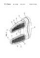
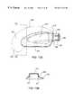
- FIGS. 1A and 1Bare top plan and top perspective views, respectively, of a tissue stabilizer constructed according to the principles of the present invention.
- FIG. 2is a bottom perspective view of the tissue stabilizer of FIGS. 1A and 1B.
- FIG. 3is a cross-sectional view taken along line 3 — 3 as shown in FIG. 1 A.
- FIG. 4is a cross-sectional view taken along line 4 — 4 as shown in FIG. 1 A.
- FIG. 5is a bottom perspective view of an alternate construction of a tissue stabilizer according to the principles of the present invention.
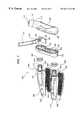
- FIG. 6is an exploded perspective view of a tissue stabilizer.
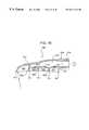
- FIG. 7is an exploded perspective view of an alternate construction of a tissue stabilizer.
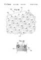
- FIG. 8Ais a magnified partial perspective view of a contacting surface of a preferred perforated screen for use in a tissue stabilizer.
- FIG. 8Bis a partial cross-sectional view showing the perforated screen configuration of FIG. 8A engaged against a tissue structure.
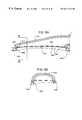
- FIGS. 9A and 9Bare partial cross-sectional views of a tissue stabilizer foot having a perimeter seal.
- FIG. 10is a partial cross-sectional view of a tissue stabilizer foot having an alternate perimeter seal.
- FIG. 11is a partial cross-section view of a tissue stabilizer foot having an alternate perimeter seal.
- FIG. 12is a top plan view of a tissue stabilizer having an alternative perimeter seal.
- FIG. 13Ais a top perspective view of the stabilizer foot of FIG. 12 .
- FIG. 13Bis a cross-sectional view taken along line 13 B— 13 B as shown in FIG. 13 A.
- FIG. 14is a bottom perspective view of an alternate construction of a tissue stabilizer according to the principles of the present invention.
- FIG. 15is a cross-sectional view of one of the stabilizer feet of FIG. 14 .
- FIG. 16is a bottom plan view of an alternate construction of a stabilizer foot according to the principles of the present invention.
- FIG. 17is a cross-sectional view taken along line 17 — 17 as shown in FIG. 16 .
- FIG. 18is a bottom plan view of an alternate construction of a stabilizer foot.
- FIG. 19is a cross-sectional view taken along line 19 — 19 as shown in FIG. 18 .
- FIG. 20is a bottom plan view of an alternate construction of a stabilizer foot.
- FIG. 21is a cross-sectional view taken along line 21 — 21 as shown in FIG. 20 .
- FIG. 22is a partial cross-sectional view of an alternate construction of a tissue stabilizer according to the principles of the present invention.
- the present inventioninvolves surgical instruments and methods for stabilizing tissue during a surgical operation.
- the devices described hereinmay be used in a wide variety of surgical applications that require a tissue structure to be stabilized or immobilized to provide a substantially stable and motionless surgical field on which a surgical procedure can be performed.
- the preferred embodiments described in detail beloware directed to the stabilization of a portion of the heart to facilitate a surgical procedure on or within the heart, such as a coronary artery bypass graft (CABG) procedure.
- CABGcoronary artery bypass graft
- the devices and methods of the present inventionmay have application in both conventional stopped-heart and beating heart procedures, they are preferably used to stabilize the beating heart during a CABG operation which has been specially developed to facilitate completion of an anastomosis, typically between a target coronary artery and a bypass graft or source artery, without requiring cardiac arrest and cardiopulmonary bypass.
- a typical beating heart CABG procedureinvolves accessing the beating heart by way of a sternotomy, mini-sternotomy, thoracotomy, mini-thoracotomy, or other suitable access incision, positioning a tissue stabilizer on, around or adjacent a coronary artery to stabilize the coronary artery, creating an arteriotomy in the coronary artery, and anastomosing the bypass graft or source artery to the arteriotomy.
- the tissue stabilizerhas a heart engaging member at one end for engaging the surface of the beating heart and is connected at the other end to a stationary object such as a sternal retractor, rib retractor, or other such stationary structure.
- the devices of the present inventioninvolve tissue stabilizers which provide superior-engagement with the surface of the heart.
- the tissue stabilizermay have one or more stabilizer feet which provide for adjustment of the orientation of the features which contact or engage the surface of the heart.
- the orientationmay be adjusted to ensure the engaging features will be properly aligned with the surface of the heart.
- the orientationmay be adjusted to yield an optimum presentation of the target coronary artery and, in particular, the location at which the anastomosis will be performed.
- the stabilizer feetmay include one or more compliant or flexible seals to ensure that there will be no vacuum leaks between the stabilizer foot and the surface of the heart.
- the stabilizer footmay have one or more portions which are adjustable relative to each other so that the stabilizer foot may be shaped according to the requirements of a particular surgical procedure or according to the specific anatomical features or characteristics of each individual patient.
- Tissue stabilizer 100preferably has stabilizer feet 105 and 110 which typically engage the surface of the heart on opposite sides of a coronary artery. Tissue stabilizer 100 is typically positioned such that the coronary artery runs lengthwise in the space between stabilizer feet 105 and 110 .
- tissue stabilizer 100preferably has a construction that does not occlude or otherwise contact the vessel as stabilizer feet 105 and 110 are placed on opposite sides of the coronary vessel portion to be stabilized.
- stabilizer feet 105 , 110are spaced apart at a distance such that a coronary artery can be positioned therebetween.
- the basemay include a recessed or raised portion to ensure that the vessel is not contacted by the stabilizer.
- manifold base 120to which stabilizer feet 105 and 110 are attached, preferably has raised portion 126 under which the coronary vessel may pass without contact when stabilizer feet 105 and 110 are engaged to stabilize the heart in the vicinity of the coronary vessel.
- Stabilizer feet 105 and 110are connected to manifold base 120 which will typically have mounting or connecting features for operably attaching a suitable shaft or other such structure.
- manifold base 120has a ball 135 extending therefrom.
- a shaft(not shown), preferably having a suitably constructed socket, may be provided to engage ball 135 .
- the shaftmay be used to position tissue stabilizer 100 at the desired location on the heart and may provide the necessary structure to hold the tissue stabilizer substantially motionless against the forces generated by the beating heart.
- the shaft or other appropriate connecting structuremay be operably connected to the tissue stabilizer using any suitable connection which allows the desired maneuverability of the tissue stabilizer relative to the shaft. Suitable stabilizer shafts and their connections to a tissue stabilizer are described in co-pending U.S.
- Stabilization of the targeted tissuemay be achieved by applying a localized compressive force to the heart through stabilizer feet 105 and 110 using an appropriate connecting structure attached to ball 135 .
- the tissue contacting features on the bottom of stabilizer feet 105 and 110are designed to have high friction against the surface of the heart, for example, by using a textured surface or the like.
- negative pressure or vacuummay be applied to stabilizer feet 105 and 110 so that the beating heart may be engaged or captured by the suction created within a vacuum chamber or a plurality of suction ports.
- the heart portionmay be rendered substantially motionless by fixing an attached shaft to a stationary object, such as a surgical retractor as described above.
- ball 135is preferably connected to manifold base 120 by way of post 130 .
- Ball 135 and post 130may have any suitable construction which provides the necessary attachment of the stabilizing shaft or other stabilizing structure and which can withstand the loads required to stabilize the beating heart with minimal deflection.
- the ball and postmay be integrally molded features on the manifold base itself or may be separate components mechanically secured to manifold base 120 using, for example, a threaded or snap-fit connection or the like.
- manifold base 120is constructed of a plastic material
- post 130is rigidly attached to support member 155 which is made of a metal such as aluminum or stainless steel.
- support member 155is secured within holding features such as cavities or pockets 156 and 158 formed in rear manifold portion 124 and front manifold portion 122 , respectively.
- Support member 155may be secured within pockets 156 and 158 by a simple interference fit as manifold portions 122 and 124 are urged into their final assembled positions or may be held in place using mechanical fasteners, adhesive, or suitable bonding or welding technique.
- manifold base 120When the tissue stabilizer is configured to use vacuum stabilization or vacuum-assisted stabilization, manifold base 120 preferably has a fitting or the like to which a vacuum supply may be connected. In a preferred embodiment, manifold base 120 has inlet tube 115 having an inlet opening 117 . Inlet tube 115 is preferably in fluid communication with a hollow space or chamber 134 formed within manifold base 120 . Manifold base 120 and internal chamber 134 provides for convenient distribution of a single vacuum source connected to inlet tube 115 to multiple stabilizer feet fluid connections, in this case to stabilizer feet 105 and 110 .
- Inlet tube 115may have one or more barbs 119 to facilitate the secure and leak-free attachment of a length of flexible tubing (not shown) coming from a vacuum pump or other vacuum source (not shown) as is commonly known in the art.
- inlet tube 115may be replaced with a generally cylindrical bore adapted to accept an O-ring sealed fitting forming a dynamically sealed rotating connection between the fitting and the manifold base similar in construction to the stabilizer foot connection described below with regard to FIG. 3 .
- manifold base 120is preferably made in two or more portions and fixed together to form a sealed, hollow interior.
- manifold base 120has front manifold portion 122 and rear manifold portion 124 which may be bonded together along bond line 125 as shown.
- the internal chamber 134may reside primarily in either or both of front and rear manifold portions 122 and 124 .
- a portion of internal chamber 134is formed in rear manifold portion 124 and one or more internal cavities 128 are included within front manifold portion 122 .
- the manifold portionsare preferably injection molded and may be fixed together using standard mechanical fasteners, a snap fit construction, or any suitable adhesive, bonding, sealing, or welding technique compatible with the material of manifold base 120 .
- the manifold portionsmay have close fitting overlapping flanges.
- rear manifold portion 124has an inner flange 152 and front manifold portion 122 has an overlapping outer flange 154 . This construction provides a particularly reliable sealed junction between front and rear manifold portions 122 and 124 , especially when used in conjunction with a suitable gap-filling adhesive.
- stabilizer feet 105 and 110are secured to manifold base 120 .
- Stabilizer feet 105 and 110may be fixed in place in any convenient manner and immovable relative to manifold base 120 . More preferably, however, stabilizer feet 105 and 110 are moveable relative to manifold base 120 . Most preferably, stabilizer feet 105 and 110 are independently moveable with respect to each other as well. This allows the tissue engaging features of the tissue stabilizer to be optimally adjusted with respect to the size and shape of the tissue to be stabilized and, once engaged and in operation, may also allow the stabilizer feet to be moved to optimize the presentation of the stabilized tissue, and more particularly the target coronary artery.
- stabilizer feet 105 and 110are connected to manifold base 120 in a manner which allows each foot to rotate relative to the manifold base 120 .
- the axis about which the stabilizer feet 105 and 110 rotatemay be in any orientation that provides the desired stabilizer feet orientation relative to the heart for optimum engagement or tissue presentation.
- the axis of rotationis oriented generally in the same direction as the direction stabilizer feet 105 and 110 extend from manifold base 120 , although the axis of rotation and the direction the stabilizer feet extend may be offset from each other.
- the axis of rotation of the first stabilizer foot relative to the base membermay be offset from the axis of rotation of the second stabilizer foot relative to the base member.
- the axis of rotationis preferably at an angle of no more than about 25° with respect to the included plane or surface approximated by the features adapted to engage the tissue surface to be stabilized. More preferably, the axis of rotation for each stabilizer foot 105 and 110 is generally parallel to the features adapted to engage the tissue surface to be stabilized.
- the axis of rotationis oriented as described above relative to a best-fit plane approximating the tissue engaging features or a central tangent plane.
- the axis of rotation for each stabilizer footis also angled with respect to each other at an angle of no more than about 30°, and more typically the axis of rotation of stabilizer foot 105 is generally parallel to the axis of rotation of stabilizer foot 110 .
- a preferred stabilizer foot connectionis illustrated with respect stabilizer foot 110 .
- Manifold base 120and more specifically front manifold portion 122 , has a bore 149 extending through the exterior wall.
- Stabilizer foot 110has an end portion or fitting 137 having an outside diameter 148 adapted to mate with bore 149 to allow fitting 137 , and thus stabilizer foot 110 , to rotate about central axis 133 of bore 149 .
- central axis 133is offset from the features which engage the tissue to be stabilized, in this case perforated screen 141 .
- This offsetfacilitates improved vessel presentation as stabilizer feet 105 and 110 are rotated because, in addition to changing the overall orientation of the tissue engaging features, the eccentric relation of the tissue engagement features relative to the central axis moves the stabilizer feet together or apart as the stabilizer feet are rotated. This action allows the tissue and included coronary artery held between the stabilizer feet to be stretched or compressed as desired by rotating either or both of stabilizer feet 105 and 110 after they have become operably engaged with the tissue.
- the tissue stabilizer 100is constructed to supply a negative pressure or vacuum to stabilizer feet 105 and 110 to assist in the engagement of the surface of the heart.
- Stabilizer feet 105 and 110preferably have a hollow interior 132 to which a vacuum may be supplied through vacuum inlet 131 of fitting 137 , vacuum chamber 134 , and vacuum inlet tube 115 , which are interconnected in a manner which does not allow any significant vacuum leaks.
- the structurescomprise a vacuum conducting chamber that communicates a negative pressure from a vacuum source to the surface of the beating heart.
- Vacuum inlet tube 131may optionally have restriction or aperture (not shown) provided therein to restrict the amount of flow through vacuum inlet tube 131 when the sealed engagement against the tissue to be stabilized is broken. This allows vacuum chamber 134 of manifold base 120 to continue to provide sufficient vacuum to one stabilizer foot even when the engagement seal of the other stabilizer foot is compromised.
- the rotating connection between stabilizer feet 105 and 110 and manifold base 120must be sealed to prevent any vacuum loss.
- Thisis preferably accomplished using an appropriate dynamic annular or shaft seal that seals between the stabilizer foot and manifold base 120 but yet allows for rotation of the stabilizer foot within bore 149 without incurring any vacuum loss.
- a sealsuch as O-ring 145 is positioned within an annual seal cavity 146 at the entrance of bore 149 . The seal is captured and compressed within seal cavity 146 by cooperating annular seal flange 147 provided on stabilizer feet 105 and 110 as the stabilizer feet are urged into final position.
- Stabilizer feet 105 and 110may be held in position by operation of an spring clip or e-clip 150 assembled to fitting 137 just beyond its exit of bore 149 .
- Hollow interior 132is generally a closed chamber except for one or more openings for engaging the heart.
- the engagement opening or openingsmay be in the form of a perforated screen having a relatively large number of perforations or small holes which engage the surface of the heart, a single opening having a defined perimeter for sealing against the surface of the heart, or a plurality of individual suction pods each having a sealing perimeter.
- stabilizer feet 105 and 110include thin perforated sheets or screens 140 and 141 , respectively which have a front surface 144 oriented to engage the surface of the heart.
- Perforated screens 140 and 141are supported around their perimeter by a support step 138 which preferably has a raised perimeter edge or border 139 .
- Perforated screens 140 and 141are characterized as having a plurality of perforations or holes 142 .
- perforated screens 140 and 141are fabricated to have a contour or shape which corresponds to the expected size and shape of the cardiac tissue to be stabilized.
- perforated screen 140 and 141may have a radius, R, which may be constant or variable.
- each perforation 142As front surfaces 144 of perforated screens 140 and 141 are urged against the surface of the heart (or other tissue structure), the heart begins to contact front surface 144 around each perforation 142 and thus sealingly covering each perforation 142 . As each perforation 142 is covered in this manner, the relatively small portion of tissue residing over each perforation 142 is subjected to the vacuum existing within hollow interior 132 and is accordingly sucked against, and even slightly into, perforation 142 .
- the unperforated material between adjacent perforationsis between about 0.015 inches (0.38 mm) and about 0.025 inches (0.635 mm) at its smallest point, most preferably about 0.02 inches (0.51 mm), and the diameter of the perforations are from about 0.06 inches (1.524 mm) to about 0.09 inches (2.286 mm).
- FIGS. 8A and 8Billustrate a perforated member 400 having a front contact surface 410 which has a number of perforations or holes 415 .
- the unperforated material of member 400has a plurality of projections 420 extending outwardly from contact surface 410 .
- a plurality of projectionsare generally equally spaced around each perforation 415 .
- the projectionsmay be formed, for example, by chemical machining or etching. Projections 420 operate to more aggressively bite or engage tissue structure 425 as it is urged into perforation 415 by operation of an applied vacuum.
- FIG. 5illustrates tissue stabilizer 200 having a perimeter sealing member 215 disposed at the bottom of each stabilizer foot 205 and 210 . Perforated screens 140 and 141 are recessed from perimeter sealing member 215 .
- perimeter sealing member 215makes contact with the surface of the heart around substantially its entire perimeter, the portion of the heart tissue within the perimeter is subjected to the negative pressure existing within the hollow interior of stabilizer feet 205 and 210 and is urged into engagement with stabilizer feet 205 and 210 .
- the negative or vacuum pressuremay be sufficient to displace the portion heart tissue within the vacuum chamber created by perimeter sealing member 215 into forced contact with perforated screens 140 and 141 .
- perforated screensmay optionally have projections as described above.
- FIG. 6An exploded view of tissue stabilizer 200 is shown in FIG. 6 .
- Front manifold portion 122has first and second bores 222 and 223 for receiving tubular members or fittings 208 associated with stabilizer feet 205 and 210 , respectively.
- Fittings 208are preferably integrally molded features of stabilizer feet 205 and 210 , but could alternatively be separate fittings secured to the stabilizer feet by way of, for example, a bonded, welded, or threaded connection.
- Fittings 208have a flange 212 for retaining and compressing O-ring 202 within the seal cavity (not visible in this view) and groove 214 for receiving a external retaining ring, preferably of the spring type, e-type or the like.
- Fittings 208preferably have a vacuum inlet opening 220 for communicating the negative pressure within manifold base 120 to the hollow interior region within stabilizer feet 205 and 210 .
- Stabilizer foot 205may be assembled to front manifold portion 222 by installing O-ring 202 over fitting 208 and then installing fitting 208 through bore 222 . Fitting 208 and stabilizer foot 205 is secured in place by securing an external retaining ring 218 , into place within groove 214 . The same procedure is then used to install stabilizer foot 210 to manifold portion 222 .
- Post support member 155is placed in the proper location between or within front and rear manifold portion 122 , or 124 as the two manifold portions are brought together in the presence of an appropriate bonding agent or adhesive to make the assembly leak-free, air-tight, and permanent.
- Perforated screens 140 and 141may be secured to stabilizer feet 205 and 210 at any convenient time before or after the assembly procedure just described.
- Tissue stabilizer 300shown in exploded view in FIG. 7, allows stabilizer feet 305 and 310 to be assembled to front manifold portion 122 using a simple snap-fit construction instead of an external retaining ring.
- the fitting portions of stabilizer feet 305 and 310include a seal flange 310 , an uninterrupted base portion 304 and a number of flexures 302 having raised end features 303 .
- Flexures 302allow raised features 303 to flex inwardly so that they fit through bore 222 and 223 and then flex outwardly as they exit bores 222 and 223 , thus becoming locked in place.
- Tissue stabilizer 300may be assembled using the same basic procedure as described above with reference to tissue stabilizer 200 .
- the front and rear manifold portions 122 and 124can be fully assembled and leak tested (if desired) before stabilizer feet 305 and 310 are installed.
- post support member 155is positioned in place in or between front and rear manifold portions 122 and 124 as the two manifold portions are brought together in the presence of an appropriate bonding agent or adhesive to secure the manifold base assembly together.
- An O-ring 202is then placed over uninterrupted portion 304 adjacent flange 310 and raised features 303 on flexures 302 are urged through bore 222 or 223 until it exits the bore and snaps open and into place, thus fixing stabilizer foot 305 or 310 to the assembled manifold base.
- Tissue stabilizer 300shows a variation in which a stabilizer shaft 307 is pre-installed on ball 135 .
- Stabilizer shaft 307has a socket housing 306 which is permanently operably attached to ball 135 .
- the ball 135 and post 130is dropped into housing 306 from a distal direction prior to fixing shaft 307 thereto.
- Post support member 155is then fixed to the proximal end of post 130 , rendering the assembly essentially inseparable. This eliminates any possibility of accidental separation of the stabilizer foot from the stabilizer shaft.
- stabilizer feet 305 and 310may be rotated to obtain the desired orientation of each foot to provide maximum stabilization based on the clinical situation presented by an individual patient.
- Stabilizer feet 305 and 310may be provided with additional features to facilitate adjustment of stabilizer feet 305 and 310 after engagement with the tissue to be stabilized.
- the featuresmay be any holes, lever, protrusion, projection, or other suitable feature that allows the stabilizer feet to be easily manipulated during use. Since it is desirable for the device to have an unobstructingly low-profile, especially in the area of the stabilizer feet, the adjustment features are preferably one or more blind holes 308 adapted to receive a blunt instrument for manipulating the orientation of stabilizer feet 305 and 310 .
- a hex or nut-shaped featurecould be added to each stabilizer foot distal of the seal flange for use with an appropriately sized wrench or the like to rotate the stabilizer feet.
- Perimeter sealing member 215may have a variety of constructions. Sealing member 215 may simply be an integral extension of the stabilizer foot material. In that instance, sealing member 215 will typically be a relatively hard polymer or plastic material. Sealing member 215 may also be a relatively soft elastomer which is attached to or over-molded on stabilizer feet 205 and 210 . Sealing member 215 may also be constructed of a compressible foam material, preferably a closed cell foam. The elastomer or foam materials will preferably compress, deflect or otherwise yield somewhat as the stabilizer feet become engaged with the irregular surface of the heart. When sealing member 215 is constructed of an elastomer or foam material, it will preferably have a durometer hardness in the range from about 35 Shore-A to about 100 Shore-A depending on the geometrical configuration of sealing member 215 .
- the perimeter sealhas a variable thickness around its perimeter to provide a more reliable seal against the curvature of the surface of the heart, especially when the heart continues to beat during the procedure.
- FIGS. 9A and 9Bshow a portion of a stabilizer foot 430 having a perimeter seal 440 with a variable height or thickness around its perimeter. Similar to the previously discussed configurations, stabilizer foot 430 has a hollow interior 449 to which a negative pressure is communicated.
- Perforated screen 435has a plurality of holes or perforations 437 and is mounted in position on step feature 447 within stabilizer foot 430 .
- Perimeter seal 440is mounted at or near the bottom of stabilizer foot 430 , and is preferably retained within a groove or step 448 .
- the height that perimeter seal 440 extends from the bottom of stabilizer foot 430typically varies at different locations around the perimeter of perimeter seal 440 .
- the tip height 441 and rear height 443is generally greater than midpoint height 442 along either side of the stabilizer foot.
- height 446 of perimeter seal 440 along the inside of stabilizer foot 430is generally less that the outside height 444 at a corresponding location along the stabilizer foot 430 .
- perimeter seal 440is made from an elastomer, a closed-cell foam, or other flexible or compressible material to further optimize the ability of stabilizer foot to maintain its seal on the tissue to be stabilized. If the seal is broken or otherwise compromised, the stabilizer foot may disengage from the surface of the heart, adversely affecting stabilization. Seal 440 may be fixed to the stabilizer foot using an adhesive or bonding agent or may be made integral with the stabilizer foot using an injection over-molding process wherein seal 440 is molded over the stabilizer foot.
- Stabilizer foot 450again has a hollow interior 449 and a perforated screen 435 having perforations or holes 437 .
- stabilizer foot 450has a flexible seal 455 having first and second legs 458 and 459 disposed in an angular relationship which operates as a highly flexible joint allowing perimeter edge 456 to move relatively freely towards and away from the bottom of stabilizer foot 450 as required to effectuate a reliable seal against the surface of the tissue to be stabilized. For example, if the tissue under vacuum engagement with stabilizer foot 450 contracts and moves away from the tip of stabilizer foot 450 , flexible seal 455 can easily follow the movement to a new extended position 455 ′ without the seal being broken.
- Flexible seal 455is preferably made from a medical grade elastomeric material such as silicone, urethane rubber, neoprene, nitrile rubber, hytrel, kraton, or other suitable material. Flexible seal 455 may be separately formed and later attached to stabilizer foot 450 or may be integrally over-molded onto stabilizer foot 450 . For secure attachment to stabilizer foot 450 , flexible seal 455 may optionally be provided with seal base portion 457 .
- stabilizer foot 460has flexible seal 465 having continuously connected alternating flexible legs in the form of a bellows.
- Flexible seal 465may include a base 467 to facilitate attachment to the bottom of stabilizer foot 460 and has a perimeter edge 466 to effectuate a reliable seal against the surface of the tissue to be stabilized.
- This type of sealgenerally compresses to a relatively solid, stable structure as the stabilizer foot is urged against the surface of the tissue, has a the ability to follow moving tissue over a relatively long travel if required, and yet occupies only a very small amount of space around the perimeter of the stabilizer foot.
- Tissue stabilizer 470has a manifold base 473 comprised of front manifold portion 472 , rear manifold portion 474 having vacuum inlet tube 471 , and ball 476 to which a stabilizing shaft may be attached.
- Stabilizer feet 475 and 480may be attached to stabilizer base 473 in any of the ways discussed above.
- stabilizer feet 475 and 480have a fitting portion 485 which includes an uninterrupted cylindrical portion 486 , one or more flexures 487 each having raised features 488 that provide a positive snap-fit joint in cooperation within cylindrical bores formed in front manifold portion 472 as described in detail above.
- fitting 485has a flange 479 for retaining and compressing a shaft seal or the like.
- Stabilizer feet 475 and 480have attached thereto flexible seals 482 and 477 , respectively.
- Flexible seals 477 and 482may extend completely around the perimeter of stabilizer feet 480 and 475 . More preferably, stabilizer feet 475 and 480 have at least one portion of its perimeter having a flexible seal and at least one portion without a flexible seal. According to this variation of the present invention, the stabilizer feet 475 and 480 are primarily sealed against the target tissue by operation of their own perimeter edge 481 .
- Flexible seals 482 and 477are provided generally outside of perimeter edge 481 to provide a form of secondary or back-up seal in the event the seal at perimeter edge 481 becomes compromised as a result of misalignment or movement of the tissue.
- Flexible seals 477 and 482are preferably sufficiently flexible to remain in contact with the movements of the beating heart so that when the seal breaks along 481 perimeter edge the vacuum loss is contained within flexible seal 482 or 477 . This containment typically allows the comprised area of perimeter edge 481 to become re-engaged against the tissue without significant vacuum loss.
- the vacuum seal formed at the perimeter edge of the stabilizer feetmay be most likely to break at the tip region or along the outside edge of the stabilizer foot as the heart contracts away from the site of stabilization.
- flexible seals 477 and 482need only be associated with these problem areas, leaving inside perimeter portion 478 and the space between stabilizer feet 475 and 480 open to avoid obstructing the surgical field of the anastomosis.
- Flexible seals 477 and 482have a contoured outer periphery 483 which may be a relatively large distance away from the outer extents of the stabilizer feet 475 and 480 and may include extended tip portions 484 .
- Flexible seals 477 and 482preferably have a top portion for attaching to the stabilizer feet about the perimeter edge 481 .
- Flexible seals 477 and 482may be fixed in place using an adhesive or bonding agent or may be integrally over-molded as part of stabilizer feet 475 and 480 .
- Another way to prevent a complete loss of engagement and stabilization of the target tissue due to a compromised perimeter seal resulting from misalignment of the stabilizer feet or movement of the target tissue to be stabilizedis to partition the vacuum chamber within the stabilizer feet into a plurality of chambers connected to the vacuum source through only a small aperture. In that way, a vacuum leak at a single location will result in a reduced ability to maintain engagement of that partitioned section only and will not immediately compromise the engagement of the entire stabilizer foot.
- Tissue stabilizer 500has a manifold base 501 , preferably having front and rear manifold portions 504 and 502 , to which first and second stabilizer feet 505 and 506 are attached.
- First and second stabilizer feet 505 and 506have perimeter seal edges 507 and 508 which generally define the extents of the vacuum chambers for each stabilizer foot.
- One or more partitions 509are provided to divide stabilizer feet 505 and 506 into two or more vacuum subchambers.
- stabilizer feet 505 and 506have partitions 509 which divide the vacuum space into first, second, third, and fourth vacuum subchambers 517 , 518 , 519 , and 520 , respectively.
- Vacuum feed tube 510is provided along the interior of stabilizer feet 505 and 506 to communicate the negative pressure from within the manifold base to each of subchambers 517 , 518 , 519 , and 520 .
- Vacuum feed tube 510preferably has a side opening or aperture 512 within each of subchambers 517 , 518 , and 519 .
- Vacuum feed tube 510may have an end opening or aperture 513 within subchamber 520 .
- the apertures 512 and 513facilitate the separate communication of negative pressure to each vacuum subchamber and are preferably sized such that when one subchamber encounters a vacuum leak, the aperture is restricted enough so that the vacuum in the other subchambers can be maintained by the vacuum source.
- Stabilizer feet 505 and 506are preferably rotatable with respect to manifold base 501 as discussed at length above.
- stabilizer feet 505 and 506may have a fitting portion 515 which is preferably cylindrical to cooperate with a mating bore provided in manifold base 501 .
- Fitting portion 515may have a flange 514 for retaining a shaft seal and a groove for receiving an external retaining ring to secure fitting portion 515 within manifold base 501 .
- the bottom of stabilizer feet 505 and 506may have a contoured shape having a variable or fixed radius, R.
- a flexible sealmay optionally be included along one or all of sealing edges 507 , 508 , and 511 .
- a partitioned vacuum chamber as described abovemaximizes the area exposed to negative pressure for a particular size of stabilizer foot. That is, the ratio of the surface area exposed to negative pressure divided by the total surface area included with the boundary at the bottom of the stabilizer foot is maximized by the partitioned chamber configuration just described.
- rotatable stabilizer feetcan be constructed to have a number of individual vacuum ports or pods.
- FIGS. 16 and 17illustrate stabilizer foot 550 having a plurality of individual vacuum ports.
- stabilizer foot 550has four suction ports 551 , 552 , 553 , and 554 each with a dedicated edge seal 561 .
- Negative pressureis communicated to each port through openings or apertures 560 provided in vacuum distribution passage 563 which is fluid communication with vacuum inlet 562 which in turn is placed in fluid communication with the negative pressure within a manifold base assembly having a construction as described above.
- Stabilizer foot 550may be mounted for rotation within a cooperating bore of an appropriate manifold base by way of cylindrical fitting portion 556 which may include a seal flange 555 and groove 557 for receiving an external retaining ring to secure fitting portion 556 in place.
- FIGS. 18 and 19show a variation of a stabilizer foot having a plurality of individual ports.
- Stabilizer foot 575again has a fitting portion 599 having a seal flange 598 for retaining and compressing an appropriate shaft seal to provide the desired dynamic seal as stabilizer foot 575 is rotated about fitting portion 599 .
- To facilitate even greater adjustment of the shape and orientation of stabilizer foot 575has a first foot portion 580 with at least one vacuum port and a second foot portion 585 with at least one vacuum port which are adjustable relative to one another, preferably by way of one or more malleable joints or links.
- first foot portion 580has a plurality of separate vacuum ports 581 each with a perimeter seal 582 .
- first foot portion 580has three vacuum ports 581 each supplied with negative pressure through apertures 578 in vacuum distribution channel or passage 593 .
- Second foot portion 585has at least one vacuum port 583 having perimeter seal 584 and aperture 577 in fluid communication with vacuum passage 592 .
- First foot portion 580 and second foot portion 585are preferably connected to each other by malleable tube 590 , which has a lumen or passage 591 therethrough.
- Malleable tube 590is preferably made of stainless steel, more preferably annealed stainless steel or vacuum annealed stainless steel.
- the vacuum communicated from a manifold base or other vacuum source through vacuum inlet channel 595is distributed to vacuum ports 581 and 583 through vacuum distribution channel 593 and associated apertures 578 , through malleable tube passage 591 , finally to vacuum passage 592 and associated aperture 577 .
- the orientation of second foot portion 585 and thus vacuum port 583can be adjusted relative to first foot portion 580 by simple bending it to the desired orientation. This additional adjustment tends to eliminate problems associated with obtaining a reliable seal at the tip of the stabilizer foot as the beating heart contracts away from the stabilizer, yet maintains the reliability of having ports 603 molded to a unitary relatively rigid stabilizing structure.
- Malleable tube 590may be secure to first foot portion 580 and second foot portion 585 in any convenient manner which provides a permanent and sealed connection.
- the exterior of malleable tube 590may be pressed into mating counterbores 596 and 597 provided in the ends of Vacuum passages 593 and 592 as shown.
- a suitable adhesive or bonding agentmay additionally be used to sealingly secure malleable tube 590 in place.
- malleable tube 590 and counterbores 596 and 597may be threaded together or malleable tube 590 could be insert molded within first and second foot portions 580 and 585 .
- FIGS. 20 and 21illustrate another embodiment of a stabilizer foot having foot portions which are adjustable relative to one another to improve the fit, and accordingly the operating vacuum seal, against the surface of the tissue structure to be stabilized.
- Stabilizer foot 600has a first foot portion 601 and a second foot portion 602 .
- First foot portion 601has one or more, preferably three, vacuum ports 603 and second foot portion 602 has one or more vacuum ports 608 .
- Each of vacuum ports 603 and 608preferably have a flexible or compressible perimeter seal 604 and 609 , respectively, preferably made of a medical grade elastomer or foam.
- Negative pressureis supplied to vacuum ports 603 and 608 through openings or apertures 715 and 716 which in fluid communication with vacuum passages 711 and 712 .
- Negative pressureis supplied to vacuum passage 711 through inlet channel or passage 710 of fitting portion 718 .
- Fitting portion 718connected to a vacuum chamber or source within a manifold base or like structure as described above.
- First foot portion 601 and second foot portion 602are made adjustable relative to each other by providing one or more malleable links spanning between the two portions.
- first and second malleable members 606 and 607are located off-center with respect vacuum ports 603 and 608 . The off-center position of malleable members 606 and 607 better protects against excessive torsional loads applied to tube 605 if second foot portion 602 were twisted relative to first foot portion 601 .
- Malleable members 606 and 607may be glued or bonded within cavities or bores provided within first and second foot portions 601 and 602 or may be insert molded during fabrication of the foot portions.
- Tube 605fluidly connects vacuum passages 711 and 712 .
- tube 605may be malleable or may be a flexible tubing material.
- tube 605is assembled within counterbores 713 and 714 .
- the tissue stabilizers of the present inventionallow the stabilizer feet, and in particular the features which operate to engage the surface of the tissue to be stabilized, to be optimally adjusted to for a specific surgical procedure or to adjust for variations in size and orientation of a patient's anatomy.
- the stabilizer feetcan be adjusted after engagement to the tissue to be stabilized to produce an improved presentation of the tissue subject to the surgical procedure.
- one or both of the stabilizer feetare adjusted to the desired orientation relative to the manifold base and each other.
- the orientation of the stabilizer feetare adjusted to account for the size and shape of the tissue to be stabilized, for example a target site on the surface of the heart. If either of the stabilizer feet have an adjustable portion, it may also be adjusted at this time.
- the tissue stabilizeris brought into engagement with the tissue to be stabilized and the vacuum is applied.
- the stabilizer shaftis then locked into place to immobilize the tissue stabilizer and the engaged tissue.
- one or both of the stabilizer feetmay be rotated relative to the manifold base until the tissue between or adjacent the stabilizer feet obtains the best possible presentation for the procedure to be performed. If there appears to be any discernible vacuum leaks associated with the engagement of the stabilizer feet against the target tissue, the orientation of the stabilizer feet may be further adjusted or, if applicable, the feet portions may be adjusted, to eliminate or minimize vacuum leaks at the interface between the stabilizer feet and the target tissue.
- FIG. 22illustrates tissue stabilizer 725 having a stabilizer foot rotatably connected with respect to a portion of common tubing having a flared end.
- Tube 740may be a malleable tube, for example made of annealed stainless steel, which may be connected proximally to a manifold (not shown) shared with a second stabilizer foot or may be connected directly to a fixed mount (not shown) to effectuate stabilization.
- stabilizer foot 730is connected to housing 735 which rotates about tube 740 .
- Tube 740has a flared end 742 as is commonly known in the art.
- a shaft seal, such as O-ring 732is place over tube 740 adjacent flared end 742 .
- Housing 735has a first bore 737 and a second larger bore 738 .
- First bore 737is larger than the outside diameter of tube 740 but preferably smaller than the diameter of flanged end 742 .
- Second bore 738is preferably slightly larger than flanged end 742 .
- Tube 740 with O-ring 732is assembled through second bore 738 until the O-ring is compressed at the distal entrance to first bore 737 .
- An O-ring cavity 736may be provided if desired.
- Fitting portion 734is inserted into second bore 738 and permanently fixed in place preferably using a fluid tight connection such as pipe threads, adhesive, bonding agent, welding, brazing, etc. With fitting portion 734 fixed to housing 735 , stabilizer foot 730 and housing 735 may be rotated relative to tube 740 without any appreciable vacuum leakage. Stabilizer foot 730 may be of any desirable configuration.
Landscapes
- Health & Medical Sciences (AREA)
- Life Sciences & Earth Sciences (AREA)
- Surgery (AREA)
- Heart & Thoracic Surgery (AREA)
- Engineering & Computer Science (AREA)
- Biomedical Technology (AREA)
- Nuclear Medicine, Radiotherapy & Molecular Imaging (AREA)
- Medical Informatics (AREA)
- Molecular Biology (AREA)
- Animal Behavior & Ethology (AREA)
- General Health & Medical Sciences (AREA)
- Public Health (AREA)
- Veterinary Medicine (AREA)
- Prostheses (AREA)
Abstract
Description
Claims (39)
Priority Applications (3)
| Application Number | Priority Date | Filing Date | Title |
|---|---|---|---|
| US09/366,190US6511416B1 (en) | 1999-08-03 | 1999-08-03 | Tissue stabilizer and methods of use |
| US10/272,036US7503891B2 (en) | 1999-08-03 | 2002-10-15 | Tissue stabilizer and methods of use |
| US12/365,992US20090137865A1 (en) | 1999-08-03 | 2009-02-05 | Tissue Stabilizer and Methods of Use |
Applications Claiming Priority (1)
| Application Number | Priority Date | Filing Date | Title |
|---|---|---|---|
| US09/366,190US6511416B1 (en) | 1999-08-03 | 1999-08-03 | Tissue stabilizer and methods of use |
Related Child Applications (1)
| Application Number | Title | Priority Date | Filing Date |
|---|---|---|---|
| US10/272,036ContinuationUS7503891B2 (en) | 1999-08-03 | 2002-10-15 | Tissue stabilizer and methods of use |
Publications (1)
| Publication Number | Publication Date |
|---|---|
| US6511416B1true US6511416B1 (en) | 2003-01-28 |
Family
ID=23442011
Family Applications (3)
| Application Number | Title | Priority Date | Filing Date |
|---|---|---|---|
| US09/366,190Expired - Fee RelatedUS6511416B1 (en) | 1999-08-03 | 1999-08-03 | Tissue stabilizer and methods of use |
| US10/272,036Expired - Fee RelatedUS7503891B2 (en) | 1999-08-03 | 2002-10-15 | Tissue stabilizer and methods of use |
| US12/365,992AbandonedUS20090137865A1 (en) | 1999-08-03 | 2009-02-05 | Tissue Stabilizer and Methods of Use |
Family Applications After (2)
| Application Number | Title | Priority Date | Filing Date |
|---|---|---|---|
| US10/272,036Expired - Fee RelatedUS7503891B2 (en) | 1999-08-03 | 2002-10-15 | Tissue stabilizer and methods of use |
| US12/365,992AbandonedUS20090137865A1 (en) | 1999-08-03 | 2009-02-05 | Tissue Stabilizer and Methods of Use |
Country Status (1)
| Country | Link |
|---|---|
| US (3) | US6511416B1 (en) |
Cited By (63)
| Publication number | Priority date | Publication date | Assignee | Title |
|---|---|---|---|---|
| US20030060685A1 (en)* | 2001-09-06 | 2003-03-27 | Houser Russell A. | Superelastic/shape memory tissue stabilizers and surgical instruments |
| US20030088150A1 (en)* | 1999-08-03 | 2003-05-08 | Green Harry Leonard | Tissue stabilizer and methods of use |
| US20030120268A1 (en)* | 2001-12-04 | 2003-06-26 | Estech, Inc. ( Endoscopic Technologies, Inc.) | Cardiac ablation devices and methods |
| US20030158464A1 (en)* | 2001-12-04 | 2003-08-21 | Estech, Inc. (Endoscopic Technologies, Inc.) | Methods & devices for minimally invasive cardiac surgery for atrial fibrillation |
| US20040002625A1 (en)* | 2002-06-27 | 2004-01-01 | Timothy Dietz | Apparatus and methods for cardiac surgery |
| US6676597B2 (en) | 2001-01-13 | 2004-01-13 | Medtronic, Inc. | Method and device for organ positioning |
| US20040015047A1 (en)* | 2000-02-11 | 2004-01-22 | Mager Larry F. | Tissue stabilizer |
| US20040082837A1 (en)* | 2002-10-29 | 2004-04-29 | Geoffrey Willis | Tissue stabilizer and methods of using the same |
| US6740029B2 (en) | 1999-07-08 | 2004-05-25 | Chase Medical, L.P. | Device and method for isolating a surface of a beating heart during surgery |
| US20040102771A1 (en)* | 2001-12-04 | 2004-05-27 | Estech, Inc. (Endoscopic Technologies, Inc.) | Cardiac treatment devices and methods |
| US20040138522A1 (en)* | 2002-08-21 | 2004-07-15 | Haarstad Philip J. | Methods and apparatus providing suction-assisted tissue engagement through a minimally invasive incision |
| US20040176764A1 (en)* | 2003-03-03 | 2004-09-09 | Centerpulse Spine-Tech, Inc. | Apparatus and method for spinal distraction using a flip-up portal |
| US20050010079A1 (en)* | 2002-12-06 | 2005-01-13 | Estech, Inc. | Methods and devices for cardiac surgery |
| US20060041194A1 (en)* | 2004-08-23 | 2006-02-23 | Mark Sorochkin | Surgical gripper with foldable head |
| US20060094929A1 (en)* | 2004-10-29 | 2006-05-04 | Tronnes Carole A | Distal portion of an endoscopic delivery system |
| US20060271034A1 (en)* | 2005-05-28 | 2006-11-30 | Boston Scientific Scimed, Inc. | Fluid injecting devices and methods and apparatus for maintaining contact between fluid injecting devices and tissue |
| US20070088203A1 (en)* | 2005-05-25 | 2007-04-19 | Liming Lau | Surgical assemblies and methods for visualizing and performing surgical procedures in reduced-access surgical sites |
| US7270670B1 (en) | 2003-04-21 | 2007-09-18 | Cardica, Inc. | Minimally-invasive surgical system utilizing a stabilizer |
| US20070244534A1 (en)* | 1998-03-17 | 2007-10-18 | Kochamba Gary S | Tissue stabilization and ablation methods |
| US20070244476A1 (en)* | 1998-03-17 | 2007-10-18 | Kochamba Gary S | Tissue stabilization and ablation device |
| US20070260123A1 (en)* | 2006-05-05 | 2007-11-08 | The Cleveland Clinic Foundation | Apparatus and method for stabilizing body tissue |
| US7338434B1 (en) | 2002-08-21 | 2008-03-04 | Medtronic, Inc. | Method and system for organ positioning and stabilization |
| US7445594B1 (en)* | 1995-09-20 | 2008-11-04 | Medtronic, Inc. | Method and apparatus for temporarily immobilizing a local area of tissue |
| US20080294251A1 (en)* | 2006-09-28 | 2008-11-27 | Bioventrix (A Chf Technologies' Company) | Location, time, and/or pressure determining devices, systems, and methods for deployment of lesion-excluding heart implants for treatment of cardiac heart failure and other disease states |
| US20080294154A1 (en)* | 2007-05-21 | 2008-11-27 | Estech, Inc. | Cardiac ablation systems and methods |
| US20090012510A1 (en)* | 2001-12-04 | 2009-01-08 | Endoscopic Technologies, Inc. | Cardiac ablation devices and methods |
| US20090163768A1 (en)* | 2007-12-20 | 2009-06-25 | Estech, Inc. | Magnetic introducer systems and methods |
| US20090163905A1 (en)* | 2007-12-21 | 2009-06-25 | Winkler Matthew J | Ablation device with internally cooled electrodes |
| US20090281541A1 (en)* | 2008-05-09 | 2009-11-12 | Estech, Inc. | Conduction block systems and methods |
| US20100211057A1 (en)* | 1995-01-23 | 2010-08-19 | Cardio Vascular Technologies, Inc. a California Corporation | Tissue heating device and rf heating method with tissue attachment feature |
| US20100268020A1 (en)* | 2005-06-09 | 2010-10-21 | Bioventrix (A Chf Technologies, Inc.) | Method and Apparatus For Closing Off a Portion of a Heart Ventricle |
| US20100331838A1 (en)* | 2009-06-25 | 2010-12-30 | Estech, Inc. (Endoscopic Technologies, Inc.) | Transmurality clamp systems and methods |
| US20110034915A1 (en)* | 2009-08-05 | 2011-02-10 | Estech, Inc. (Endoscopic Technologies, Inc.) | Bipolar belt systems and methods |
| US20110060331A1 (en)* | 2009-05-19 | 2011-03-10 | ESTECH, Inc. (Endoscopic Technologies, Inc) | Magnetic navigation systems and methods |
| US20110152915A1 (en)* | 2009-12-21 | 2011-06-23 | Tamer Ibrahim | Hemostatic stabilization system |
| US8052676B2 (en) | 2003-12-02 | 2011-11-08 | Boston Scientific Scimed, Inc. | Surgical methods and apparatus for stimulating tissue |
| WO2011159733A1 (en) | 2010-06-14 | 2011-12-22 | Maquet Cardiovascular Llc | Surgical instruments, systems and methods of use |
| US8083664B2 (en) | 2005-05-25 | 2011-12-27 | Maquet Cardiovascular Llc | Surgical stabilizers and methods for use in reduced-access surgical sites |
| US8182494B1 (en) | 2002-07-31 | 2012-05-22 | Cardica, Inc. | Minimally-invasive surgical system |
| US20130030252A1 (en)* | 2009-06-15 | 2013-01-31 | Ashutosh Kaul | Suction-Based Tissue Manipulator |
| US8545498B2 (en) | 2001-12-04 | 2013-10-01 | Endoscopic Technologies, Inc. | Cardiac ablation devices and methods |
| US20130282026A1 (en)* | 2012-04-23 | 2013-10-24 | Carine Hoarau | Engagement device and method for deployment of anastomotic clips |
| CN103654884A (en)* | 2013-12-11 | 2014-03-26 | 刘永安 | Minimally invasive auricular appendix dragging device-auricular appendix dragging device |
| US8968175B2 (en) | 2007-10-03 | 2015-03-03 | Bioventrix, Inc. | Treating dysfunctional cardiac tissue |
| US8979750B2 (en) | 2011-09-30 | 2015-03-17 | Bioventrix, Inc. | Trans-catheter ventricular reconstruction structures, methods, and systems for treatment of congestive heart failure and other conditions |
| US8998892B2 (en) | 2007-12-21 | 2015-04-07 | Atricure, Inc. | Ablation device with cooled electrodes and methods of use |
| US9039594B2 (en) | 2006-09-28 | 2015-05-26 | Bioventrix, Inc. | Signal transmitting and lesion excluding heart implants for pacing, defibrillating, and/or sensing of heart beat |
| US9044231B2 (en) | 2005-08-19 | 2015-06-02 | Bioventrix, Inc. | Steerable lesion excluding heart implants for congestive heart failure |
| US9119720B2 (en) | 2004-10-13 | 2015-09-01 | Bioventrix, Inc. | Method and device for percutaneous left ventricular reconstruction |
| US20150297347A1 (en)* | 2012-10-29 | 2015-10-22 | Aesculap Ag | Stabilizer for operations on the beating heart |
| US9259319B2 (en)* | 2005-08-19 | 2016-02-16 | Bioventrix, Inc. | Method and device for treating dysfunctional cardiac tissue |
| US20160331363A1 (en)* | 2003-07-08 | 2016-11-17 | Maquet Cardiovascular Llc | Organ manipulator apparatus |
| US10123821B2 (en) | 2009-09-10 | 2018-11-13 | Atricure, Inc. | Scope and magnetic introducer systems and methods |
| US10206779B2 (en) | 2015-09-10 | 2019-02-19 | Bioventrix, Inc. | Systems and methods for deploying a cardiac anchor |
| US10314498B2 (en) | 2013-05-24 | 2019-06-11 | Bioventrix, Inc. | Cardiac tissue penetrating devices, methods, and systems for treatment of congestive heart failure and other conditions |
| US10575953B2 (en) | 2013-08-30 | 2020-03-03 | Bioventrix, Inc. | Heart anchor positioning devices, methods, and systems for treatment of congestive heart failure and other conditions |
| US10588613B2 (en) | 2013-08-30 | 2020-03-17 | Bioventrix, Inc. | Cardiac tissue anchoring devices, methods, and systems for treatment of congestive heart failure and other conditions |
| US11020118B2 (en)* | 2018-04-13 | 2021-06-01 | Korea Institute Of Science And Technology | Peripheral nerve fixing apparatus |
| US20210177457A1 (en)* | 2019-12-13 | 2021-06-17 | Tautona Group IP Holding Company, LLC | Trocar positioning apparatus and methods for use |
| WO2021228924A1 (en)* | 2020-05-13 | 2021-11-18 | Christos Panotopoulos | Multifunctional surgical instrument |
| USD951440S1 (en)* | 2019-06-17 | 2022-05-10 | Terumo Cardiovascular Systems Corporation | Suction stabilizer for minimally invasive off-pump bypass surgery |
| US11478353B2 (en) | 2016-01-29 | 2022-10-25 | Bioventrix, Inc. | Percutaneous arterial access to position trans-myocardial implant devices and methods |
| US20230414212A1 (en)* | 2020-11-09 | 2023-12-28 | Terumo Cardiovascular Systems Corporation | Stabilizer tool for total endoscopic coronary artery bypass |
Families Citing this family (8)
| Publication number | Priority date | Publication date | Assignee | Title |
|---|---|---|---|---|
| US7497823B2 (en)* | 2004-06-30 | 2009-03-03 | Ethicon, Inc. | Flexible shaft stabilizing devices with improved actuation |
| US8469957B2 (en)* | 2008-10-07 | 2013-06-25 | Covidien Lp | Apparatus, system, and method for performing an electrosurgical procedure |
| US20130172694A1 (en)* | 2009-12-17 | 2013-07-04 | MEDIMETRICS Personalized Drug Delivery B.V. | Swallowable capsule for monitoring a condition |
| US8460172B2 (en) | 2010-07-29 | 2013-06-11 | Medtronic, Inc. | Tissue stabilizing device and methods including a self-expandable head-link assembly |
| US9603590B2 (en)* | 2013-03-15 | 2017-03-28 | Robert E. Michler | Single-arm stabilizer having suction capability |
| US11723718B2 (en) | 2015-06-02 | 2023-08-15 | Heartlander Surgical, Inc. | Therapy delivery system that operates on the surface of an anatomical entity |
| US10149672B2 (en) | 2015-06-30 | 2018-12-11 | Emory University | Devices and methods for stabilizing tissue |
| JP7480492B2 (en)* | 2019-10-23 | 2024-05-10 | 住友ベークライト株式会社 | Suction type stabilizer |
Citations (201)
| Publication number | Priority date | Publication date | Assignee | Title |
|---|---|---|---|---|
| US452131A (en) | 1891-05-12 | Depurator | ||
| US810675A (en) | 1905-04-24 | 1906-01-23 | Gustav F Richter | Dilator. |
| FR473451A (en) | 1914-06-15 | 1915-01-13 | Pierre Antoine Gentile | Advanced Parallel Spreader |
| GB168216A (en) | 1920-07-07 | 1921-09-01 | William J Cameron | Improvements in and relating to gagging-appliances and tongue depressors |
| US1706500A (en) | 1927-08-01 | 1929-03-26 | Henry J Smith | Surgical retractor |
| US2296793A (en) | 1942-02-02 | 1942-09-22 | Harry M Kirschbaum | Surgical retractor |
| US2590527A (en) | 1947-04-03 | 1952-03-25 | Joseph Niedermann | Suction massage device |
| US2693795A (en) | 1950-09-09 | 1954-11-09 | Herman R Grieshaber | Surgical retractor |
| US2863444A (en) | 1956-08-21 | 1958-12-09 | Winsten Joseph | Liver retractor for cholecystectomies |
| US3392722A (en) | 1965-07-29 | 1968-07-16 | Roger L. Jorgensen | Post-operative surgical valve |
| US3584822A (en) | 1968-02-26 | 1971-06-15 | John A Oram | Flexible columns |
| US3683926A (en) | 1970-07-09 | 1972-08-15 | Dainippon Pharmaceutical Co | Tube for connecting blood vessels |
| US3720433A (en) | 1970-09-29 | 1973-03-13 | Us Navy | Manipulator apparatus for gripping submerged objects |
| US3783873A (en) | 1971-09-16 | 1974-01-08 | H Jacobs | Weighted surgical clamp having foldable prop |
| US3858926A (en) | 1973-07-23 | 1975-01-07 | Ludger Ottenhues | Vacuum lifting device |
| US3882855A (en) | 1973-11-12 | 1975-05-13 | Heyer Schulte Corp | Retractor for soft tissue for example brain tissue |
| US3983863A (en) | 1975-06-02 | 1976-10-05 | American Hospital Supply Corporation | Heart support for coronary artery surgery |
| US4047532A (en) | 1975-04-21 | 1977-09-13 | Phillips Jack L | Vacuum forcep and method of using same |
| US4049002A (en) | 1975-07-18 | 1977-09-20 | Bio-Medicus, Inc. | Fluid conveying surgical instrument |
| US4048987A (en) | 1973-08-06 | 1977-09-20 | James Kevin Hurson | Surgical acid |
| US4049000A (en) | 1975-08-01 | 1977-09-20 | Williams Robert W | Suction retraction instrument |
| US4052980A (en) | 1976-06-10 | 1977-10-11 | Guenter A. Grams | Triaxial fiberoptic soft tissue retractor |
| US4217890A (en) | 1978-11-03 | 1980-08-19 | Owens Milton L | Surgical sling for positioning a harvested kidney during surgical reattachment |
| US4226228A (en) | 1978-11-02 | 1980-10-07 | Shin Hee J | Multiple joint retractor with light |
| US4230119A (en) | 1978-12-01 | 1980-10-28 | Medical Engineering Corp. | Micro-hemostat |
| US4306561A (en) | 1979-11-05 | 1981-12-22 | Ocean Trading Co., Ltd. | Holding apparatus for repairing severed nerves and method of using the same |
| US4366819A (en) | 1980-11-17 | 1983-01-04 | Kaster Robert L | Anastomotic fitting |
| US4368736A (en) | 1980-11-17 | 1983-01-18 | Kaster Robert L | Anastomotic fitting |
| US4421107A (en) | 1980-10-15 | 1983-12-20 | Estes Roger Q | Surgical retractor elements and assembly |
| US4428368A (en) | 1980-09-29 | 1984-01-31 | Masakatsu Torii | Massage device |
| US4434791A (en) | 1982-03-15 | 1984-03-06 | Humboldt Products Corp. | Surgical retractor array system |
| US4457300A (en) | 1982-06-07 | 1984-07-03 | Ohio Medical Instrument Co., Inc. | Surgical retractor |
| US4461284A (en) | 1982-09-30 | 1984-07-24 | Fackler Martin L | Surgical retaining device |
| US4492229A (en) | 1982-09-03 | 1985-01-08 | Grunwald Ronald P | Suture guide holder |
| US4617916A (en) | 1984-11-08 | 1986-10-21 | Minnesota Scientific, Inc. | Retractor apparatus |
| US4627421A (en) | 1984-08-03 | 1986-12-09 | Symbas Panagiotis N | Sternal retractor |
| US4637377A (en) | 1985-09-20 | 1987-01-20 | Loop Floyd D | Pillow or support member for surgical use |
| US4646747A (en) | 1983-10-28 | 1987-03-03 | Astra-Tech Aktiebolag | Electrode for electrocardiographic examinations |
| US4688570A (en) | 1981-03-09 | 1987-08-25 | The Regents Of The University Of California | Ophthalmologic surgical instrument |
| US4702230A (en) | 1986-12-08 | 1987-10-27 | Pilling Co. | Adapter for surgical retractor |
| USD293470S (en) | 1985-03-14 | 1987-12-29 | Adler David T | Combined adjustable positioner and holder for surgical instruments |
| US4718418A (en) | 1983-11-17 | 1988-01-12 | Lri L.P. | Apparatus for ophthalmological surgery |
| US4726356A (en) | 1985-11-12 | 1988-02-23 | Kapp Surgical Instrument, Inc. | Cardiovascular and thoracic retractor |
| US4726358A (en) | 1984-08-10 | 1988-02-23 | World Products Pty. Limited | Manipulative treatment device having pivoting links between base and supports |
| US4736749A (en) | 1985-04-26 | 1988-04-12 | Astra-Tech Aktiebolag | Holder for medical use fixed by vacuum |
| US4747395A (en) | 1983-08-24 | 1988-05-31 | Brief L Paul | Surgical retractor for bone surgery |
| US4754746A (en) | 1986-09-25 | 1988-07-05 | Cox Kenneth L | Self-retaining metatarsal spreader |
| US4803984A (en) | 1987-07-06 | 1989-02-14 | Montefiore Hospital Association Of Western Pennsylvania | Method for performing small vessel anastomosis |
| US4808163A (en) | 1987-07-29 | 1989-02-28 | Laub Glenn W | Percutaneous venous cannula for cardiopulmonary bypass |
| US4827926A (en) | 1987-06-30 | 1989-05-09 | Carol Mark P | Flexible support arm for medical instruments |
| US4829985A (en) | 1986-05-28 | 1989-05-16 | Delacroix-Chevalier | Sternal retractor |
| US4852552A (en) | 1987-09-03 | 1989-08-01 | Pilling Co. | Sternal retractor |
| US4854318A (en) | 1987-12-18 | 1989-08-08 | Scanlan International | Blood vessel holder and method of using in anastomosis |
| US4858552A (en) | 1986-03-19 | 1989-08-22 | Glatt Gmbh | Apparatus pelletizing particles |
| US4863133A (en) | 1987-05-26 | 1989-09-05 | Leonard Medical | Arm device for adjustable positioning of a medical instrument or the like |
| US4865019A (en) | 1988-02-25 | 1989-09-12 | Phillips Steven J | Retractor apparatus for use in harvesting mammary arteries during heart by-pass surgery |
| US4884559A (en) | 1987-12-04 | 1989-12-05 | Collins Jason H | Surgical speculum |
| US4925443A (en) | 1987-02-27 | 1990-05-15 | Heilman Marlin S | Biocompatible ventricular assist and arrhythmia control device |
| DE9004513U1 (en) | 1990-04-20 | 1990-06-28 | Herzberg, Wolfgang, Dr.med., 2000 Wedel | Device for achieving a liquid-tight closure of a section of the intestinal wall against its surroundings, such as the abdominal cavity |
| US4949707A (en) | 1984-11-08 | 1990-08-21 | Minnesota Scientific, Inc. | Retractor apparatus |
| US4949927A (en) | 1989-10-17 | 1990-08-21 | John Madocks | Articulable column |
| US4955896A (en) | 1985-09-27 | 1990-09-11 | Freeman Jerre M | Universal medical forcep tool |
| US4957477A (en) | 1986-05-22 | 1990-09-18 | Astra Tech Ab | Heart assist jacket and method of using it |
| US4963857A (en) | 1989-06-26 | 1990-10-16 | Sackett Robert L | Translatable dual magnets |
| US4971037A (en) | 1988-09-19 | 1990-11-20 | Pilling Co. | Surgical retractor support |
| US4973300A (en) | 1989-09-22 | 1990-11-27 | Pioneering Technologies, Inc. | Cardiac sling for circumflex coronary artery surgery |
| US4989587A (en) | 1989-04-26 | 1991-02-05 | Farley Daniel K | Sternal retractor |
| US4991578A (en) | 1989-04-04 | 1991-02-12 | Siemens-Pacesetter, Inc. | Method and system for implanting self-anchoring epicardial defibrillation electrodes |
| US4993862A (en) | 1989-08-16 | 1991-02-19 | Pilling Company | Clamp assembly for surgical retractor support |
| US5009660A (en) | 1989-09-15 | 1991-04-23 | Visx, Incorporated | Gas purging, eye fixation hand piece |
| US5011469A (en) | 1988-08-29 | 1991-04-30 | Shiley, Inc. | Peripheral cardiopulmonary bypass and coronary reperfusion system |
| US5019086A (en) | 1989-09-12 | 1991-05-28 | Neward Theodore C | Manipulable vacuum extractor for childbirth and method of using the same |
| US5025779A (en) | 1988-08-16 | 1991-06-25 | Mogens Bugge | Device intended to be used for opening the chest during surgery |
| US5037428A (en) | 1990-06-21 | 1991-08-06 | Applied Medical Technology, Inc. | Vessel approximation and alignment device |
| US5036868A (en) | 1990-01-29 | 1991-08-06 | Unilink Inc. | Anastomosis preparation technique |
| US5052373A (en) | 1988-07-29 | 1991-10-01 | Michelson Gary K | Spinal retractor |
| US5053041A (en) | 1990-03-12 | 1991-10-01 | Ansari Shapoor S | Vessel holder |
| US5080088A (en) | 1987-11-09 | 1992-01-14 | Minnesota Scientific, Inc. | Flexible retractor |
| US5098369A (en) | 1987-02-27 | 1992-03-24 | Vascor, Inc. | Biocompatible ventricular assist and arrhythmia control device including cardiac compression pad and compression assembly |
| US5119804A (en) | 1990-11-19 | 1992-06-09 | Anstadt George L | Heart massage apparatus |
| US5125395A (en) | 1990-09-12 | 1992-06-30 | Adair Edwin Lloyd | Deflectable sheath for optical catheter |
| US5131905A (en) | 1990-07-16 | 1992-07-21 | Grooters Ronald K | External cardiac assist device |
| US5133724A (en) | 1991-04-04 | 1992-07-28 | Pilling Co. | Abdominal aortic clamp |
| US5139517A (en) | 1989-11-08 | 1992-08-18 | Corral David F | Orthotopic intraventricular heart pump |
| US5150706A (en) | 1991-08-15 | 1992-09-29 | Cox James L | Cooling net for cardiac or transplant surgery |
| US5152777A (en) | 1989-01-25 | 1992-10-06 | Uresil Corporation | Device and method for providing protection from emboli and preventing occulsion of blood vessels |
| US5159921A (en) | 1990-11-27 | 1992-11-03 | Hoover Rocklin L | Surgical retractor |
| US5167223A (en) | 1989-09-08 | 1992-12-01 | Tibor Koros | Heart valve retractor and sternum spreader surgical instrument |
| US5171254A (en) | 1991-11-19 | 1992-12-15 | Sher Neal A | Eye fixation device |
| USRE34150E (en) | 1985-11-12 | 1992-12-29 | Kapp Surgical Instrument, Inc. | Cardiovascular and thoracic retractor |
| US5196003A (en) | 1990-11-06 | 1993-03-23 | Ethicon, Inc. | Endoscopic surgical instrument for taking hold of tissue |
| GB2233561B (en) | 1989-07-07 | 1993-03-24 | Engineering In Medicine Limite | Clamp assemblies |
| US5231974A (en) | 1991-05-31 | 1993-08-03 | Giglio Steven R | Self retaining retractor |
| US5256132A (en) | 1992-08-17 | 1993-10-26 | Snyders Robert V | Cardiac assist envelope for endoscopic application |
| US5287861A (en) | 1992-10-30 | 1994-02-22 | Wilk Peter J | Coronary artery by-pass method and associated catheter |
| US5293863A (en) | 1992-05-08 | 1994-03-15 | Loma Linda University Medical Center | Bladed endoscopic retractor |
| US5300087A (en) | 1991-03-22 | 1994-04-05 | Knoepfler Dennis J | Multiple purpose forceps |
| US5318013A (en) | 1992-11-06 | 1994-06-07 | Wilk Peter J | Surgical clamping assembly and associated method |
| US5336252A (en) | 1992-06-22 | 1994-08-09 | Cohen Donald M | System and method for implanting cardiac electrical leads |
| US5348259A (en) | 1992-02-10 | 1994-09-20 | Massachusetts Institute Of Technology | Flexible, articulable column |
| US5363882A (en) | 1989-10-13 | 1994-11-15 | Kabushiki Kaisha Machida Seisakusho | Bending device having a bellows |
| EP0630629A1 (en) | 1993-05-27 | 1994-12-28 | Paul Hartmann Aktiengesellschaft | Hydrogel wound dressing product |
| US5382756A (en) | 1993-01-22 | 1995-01-17 | Dagan; Gideon B. | Encapsulation closure for cables |
| US5383840A (en) | 1992-07-28 | 1995-01-24 | Vascor, Inc. | Biocompatible ventricular assist and arrhythmia control device including cardiac compression band-stay-pad assembly |
| US5417709A (en) | 1994-04-12 | 1995-05-23 | Symbiosis Corporation | Endoscopic instrument with end effectors forming suction and/or irrigation lumens |
| US5425705A (en) | 1993-02-22 | 1995-06-20 | Stanford Surgical Technologies, Inc. | Thoracoscopic devices and methods for arresting the heart |
| US5437651A (en) | 1993-09-01 | 1995-08-01 | Research Medical, Inc. | Medical suction apparatus |
| EP0668058A1 (en) | 1994-02-16 | 1995-08-23 | Novoste Corporation | Electrophysiology positioning catheter |
| US5453078A (en) | 1994-03-04 | 1995-09-26 | Merocel Corporation | Endoscopic wedge and organ positioner |
| US5452733A (en) | 1993-02-22 | 1995-09-26 | Stanford Surgical Technologies, Inc. | Methods for performing thoracoscopic coronary artery bypass |
| GB2267827B (en) | 1992-06-15 | 1995-11-08 | Himansu Kumar Dasmahapatra | A device for internal mammary artery dissection |
| US5467763A (en) | 1992-01-21 | 1995-11-21 | Mcmahon; Michael J. | Surgical instruments |
| US5480425A (en) | 1994-06-09 | 1996-01-02 | Carbomedics, Inc. | Integrated heart valve rotator and holder |
| US5498256A (en) | 1993-05-28 | 1996-03-12 | Snowden-Pencer, Inc. | Surgical instrument handle |
| US5503617A (en) | 1994-07-19 | 1996-04-02 | Jako; Geza J. | Retractor and method for direct access endoscopic surgery |
| US5509890A (en) | 1993-12-16 | 1996-04-23 | Kazama; Shigeru | Heart retractor |
| US5512037A (en) | 1994-05-12 | 1996-04-30 | United States Surgical Corporation | Percutaneous surgical retractor |
| US5514076A (en) | 1994-01-27 | 1996-05-07 | Flexmedics Corporation | Surgical retractor |
| US5514075A (en) | 1991-05-29 | 1996-05-07 | Origin Medsystems, Inc. | Properitoneal mechanical retraction apparatus and methods of using |
| US5520610A (en) | 1991-05-31 | 1996-05-28 | Giglio; Steven R. | Self retaining retractor |
| US5522819A (en) | 1994-05-12 | 1996-06-04 | Target Therapeutics, Inc. | Dual coil medical retrieval device |
| US5529571A (en) | 1995-01-17 | 1996-06-25 | Daniel; Elie C. | Surgical retractor/compressor |
| US5547458A (en) | 1994-07-11 | 1996-08-20 | Ethicon, Inc. | T-shaped abdominal wall lift with telescoping member |
| US5569274A (en) | 1993-02-22 | 1996-10-29 | Heartport, Inc. | Endoscopic vascular clamping system and method |
| US5571074A (en) | 1992-07-30 | 1996-11-05 | Temple University-Of The Commonwealth System Of Higher Education | Inflatable and expandable direct manual cardiac compression device |
| US5571215A (en) | 1993-02-22 | 1996-11-05 | Heartport, Inc. | Devices and methods for intracardiac procedures |
| US5573496A (en) | 1992-07-02 | 1996-11-12 | Mcpherson; William E. | Method of using a coil screw surgical retractor |
| US5607446A (en) | 1995-01-31 | 1997-03-04 | Beehler; Cecil C. | Pupil dilator |
| US5607421A (en) | 1991-05-01 | 1997-03-04 | The Trustees Of Columbia University In The City Of New York | Myocardial revascularization through the endocardial surface using a laser |
| US5613937A (en) | 1993-02-22 | 1997-03-25 | Heartport, Inc. | Method of retracting heart tissue in closed-chest heart surgery using endo-scopic retraction |
| US5632746A (en) | 1989-08-16 | 1997-05-27 | Medtronic, Inc. | Device or apparatus for manipulating matter |
| US5651378A (en) | 1996-02-20 | 1997-07-29 | Cardiothoracic Systems, Inc. | Method of using vagal nerve stimulation in surgery |
| EP0791330A2 (en) | 1996-02-20 | 1997-08-27 | Cardiothoracic Systems, Inc. | Surgical instruments and procedures for stabilizing the beating heart during coronary artery bypass graft surgery |
| US5662300A (en) | 1993-07-26 | 1997-09-02 | Michelson; Gary Karlin | Gooseneck surgical instrument holder |
| US5667480A (en) | 1995-10-20 | 1997-09-16 | Ethicon Endo-Surgery, Inc. | Method and devices for endoscopic vessel harvesting |
| EP0803228A1 (en) | 1996-04-26 | 1997-10-29 | United States Surgical Corporation | Surgical retractor |
| EP0808606A1 (en) | 1996-04-26 | 1997-11-26 | United States Surgical Corporation | Surgical retractor |
| US5713951A (en) | 1993-02-22 | 1998-02-03 | Heartport, Inc. | Thoracoscopic valve prosthesis delivery device |
| US5727569A (en) | 1996-02-20 | 1998-03-17 | Cardiothoracic Systems, Inc. | Surgical devices for imposing a negative pressure to fix the position of cardiac tissue during surgery |
| US5730757A (en) | 1996-02-20 | 1998-03-24 | Cardiothoracic Systems, Inc. | Access platform for internal mammary dissection |
| US5735290A (en) | 1993-02-22 | 1998-04-07 | Heartport, Inc. | Methods and systems for performing thoracoscopic coronary bypass and other procedures |
| US5749892A (en) | 1994-08-31 | 1998-05-12 | Heartport, Inc. | Device for isolating a surgical site |
| US5755660A (en) | 1995-10-31 | 1998-05-26 | Tyagi; Narendra S. | Combination surgical retractor, light source, spreader, and suction apparatus |
| US5766151A (en) | 1991-07-16 | 1998-06-16 | Heartport, Inc. | Endovascular system for arresting the heart |
| US5772583A (en) | 1994-01-21 | 1998-06-30 | Wright; John T. M. | Sternal retractor with attachments for mitral & tricuspid valve repair |
| US5782746A (en) | 1996-02-15 | 1998-07-21 | Wright; John T. M. | Local cardiac immobilization surgical device |
| US5795291A (en) | 1994-11-10 | 1998-08-18 | Koros; Tibor | Cervical retractor system |
| US5797960A (en) | 1993-02-22 | 1998-08-25 | Stevens; John H. | Method and apparatus for thoracoscopic intracardiac procedures |
| US5799661A (en) | 1993-02-22 | 1998-09-01 | Heartport, Inc. | Devices and methods for port-access multivessel coronary artery bypass surgery |
| US5813410A (en) | 1996-02-01 | 1998-09-29 | Levin; John M. | Internal body pump and systems employing same |
| US5836311A (en)* | 1995-09-20 | 1998-11-17 | Medtronic, Inc. | Method and apparatus for temporarily immobilizing a local area of tissue |
| US5846187A (en) | 1996-09-13 | 1998-12-08 | Genzyme Corporation | Redo sternotomy retractor |
| US5846194A (en) | 1998-01-23 | 1998-12-08 | Ethicon Endo-Surgery, Inc. | Surgical retraction apparatus |
| US5846193A (en) | 1997-05-01 | 1998-12-08 | Wright; John T. M. | Midcab retractor |
| US5865730A (en)* | 1997-10-07 | 1999-02-02 | Ethicon Endo-Surgery, Inc. | Tissue stabilization device for use during surgery having remotely actuated feet |
| US5868770A (en) | 1993-12-23 | 1999-02-09 | Oticon A/S | Method and instrument for establishing the receiving site of a coronary artery bypass graft |
| US5875782A (en) | 1996-11-14 | 1999-03-02 | Cardiothoracic Systems, Inc. | Methods and devices for minimally invasive coronary artery revascularization on a beating heart without cardiopulmonary bypass |
| US5876332A (en) | 1997-07-24 | 1999-03-02 | Genzyme Corporation | Surgical support member |
| US5879291A (en) | 1997-10-08 | 1999-03-09 | Ethicon Endo-Surgery, Inc. | Device used with a surgical retractor to elevate body parts |
| US5882299A (en) | 1997-01-31 | 1999-03-16 | Minnesota Scientific, Inc. | Device and procedure for minimally invasive coronary anastomosis |
| US5885271A (en)* | 1997-03-14 | 1999-03-23 | Millennium Cardiac Strategies, Inc. | Device for regional immobilization of a compliant body |
| US5888247A (en) | 1995-04-10 | 1999-03-30 | Cardiothoracic Systems, Inc | Method for coronary artery bypass |
| US5891017A (en) | 1997-01-31 | 1999-04-06 | Baxter Research Medical, Inc. | Surgical stabilizer and method for isolating and immobilizing cardiac tissue |
| US5894843A (en)* | 1996-02-20 | 1999-04-20 | Cardiothoracic Systems, Inc. | Surgical method for stabilizing the beating heart during coronary artery bypass graft surgery |
| US5899425A (en) | 1997-05-02 | 1999-05-04 | Medtronic, Inc. | Adjustable supporting bracket having plural ball and socket joints |
| US5908382A (en) | 1998-07-08 | 1999-06-01 | Koros; Tibor B. | Minimally invasive retractor for internal mammary artery harvesting |
| EP0919193A1 (en) | 1997-10-07 | 1999-06-02 | Ethicon Endo-Surgery, Inc. | A tissue stabilization device for use during surgery |
| US5913876A (en) | 1996-02-20 | 1999-06-22 | Cardiothoracic Systems, Inc. | Method and apparatus for using vagus nerve stimulation in surgery |
| US5944736A (en) | 1996-02-20 | 1999-08-31 | Cardiothoracic Systems, Inc. | Access platform for internal mammary dissection |
| US5944658A (en) | 1997-09-23 | 1999-08-31 | Koros; Tibor B. | Lumbar spinal fusion retractor and distractor system |
| US5957835A (en) | 1997-05-16 | 1999-09-28 | Guidant Corporation | Apparatus and method for cardiac stabilization and arterial occlusion |
| US5967972A (en) | 1997-03-28 | 1999-10-19 | Kapp Surgical Instrument, Inc. | Minimally invasive surgical retractor and method of operation |
| US5976080A (en) | 1996-09-20 | 1999-11-02 | United States Surgical | Surgical apparatus and method |
| US5976171A (en) | 1996-02-20 | 1999-11-02 | Cardiothoracic Systems, Inc. | Access platform for internal mammary dissection |
| US5984867A (en) | 1997-05-02 | 1999-11-16 | Heartport, Inc. | Surgical retractor and method of retracting |
| US5984865A (en) | 1998-09-15 | 1999-11-16 | Thompson Surgical Instruments, Inc. | Surgical retractor having locking interchangeable blades |
| US6007523A (en) | 1998-09-28 | 1999-12-28 | Embol-X, Inc. | Suction support and method of use |
| US6007486A (en) | 1997-10-07 | 1999-12-28 | Ethicon Endo-Surgery, Inc. | Tissue stabilization device for use during surgery having a segmented shaft |
| US6010531A (en) | 1993-02-22 | 2000-01-04 | Heartport, Inc. | Less-invasive devices and methods for cardiac valve surgery |
| US6013027A (en) | 1997-10-07 | 2000-01-11 | Ethicon Endo-Surgery, Inc. | Method for using a tissue stabilization device during surgery |
| US6015427A (en)* | 1997-07-07 | 2000-01-18 | Eclipse Surgical Technologies, Inc. | Heart stabilizer with controllable stay suture and cutting element |
| CA2197608C (en) | 1996-02-20 | 2000-02-01 | Charles S. Taylor | Surgical devices for imposing a negative pressure to stabilize cardiac tissue during surgery |
| US6019722A (en) | 1997-09-17 | 2000-02-01 | Guidant Corporation | Device to permit offpump beating heart coronary bypass surgery |
| US6029671A (en) | 1991-07-16 | 2000-02-29 | Heartport, Inc. | System and methods for performing endovascular procedures |
| US6030340A (en) | 1997-12-19 | 2000-02-29 | United States Surgical | Surgical retractor |
| US6033362A (en) | 1997-04-25 | 2000-03-07 | Beth Israel Deaconess Medical Center | Surgical retractor and method of use |
| USD421803S (en) | 1998-03-07 | 2000-03-21 | Koros Tibor B | Retractor for coronary artery bypass surgery |
| US6063021A (en) | 1998-07-31 | 2000-05-16 | Pilling Weck Incorporated | Stabilizer for surgery |
| US6071295A (en) | 1997-02-27 | 2000-06-06 | Medivas Opcab, Inc. | Device to hold an anastomotic site of coronary artery motionless and bloodless for the bypass operation |
| EP0993806A3 (en) | 1998-09-15 | 2000-06-28 | Medtronic Inc. | Apparatus for temporarily immobilizing a local area of tissue |
| US6099468A (en) | 1999-01-15 | 2000-08-08 | Kapp Surgical Instrument, Inc. | Retractor for partial sternotomy |
| US6102853A (en) | 1998-01-23 | 2000-08-15 | United States Surgical Corporation | Surgical instrument |
| US6102854A (en) | 1997-08-27 | 2000-08-15 | Coroneo Inc. | Sternum retractor for performing bypass surgery on a beating heart |
| US6152874A (en) | 1996-04-26 | 2000-11-28 | Genzyme Corporation | Adjustable multi-purpose coronary stabilizing retractor |
| US6183486B1 (en) | 1995-02-24 | 2001-02-06 | Heartport, Inc. | Device and method for minimizing heart displacements during a beating heart surgical procedure |
| US6190311B1 (en) | 1997-05-02 | 2001-02-20 | Cardiothoracic Systems, Inc. | Retractor and instrument platform for a less invasive cardiovascular surgical procedure |
| US6193652B1 (en) | 1997-10-07 | 2001-02-27 | Ethicon Endo-Surgery, Inc. | Tissue stabilization device for use during surgery having spherical curved feet |
| US6193732B1 (en) | 1999-01-08 | 2001-02-27 | Cardiothoracic System | Surgical clips and apparatus and method for clip placement |
| US6200263B1 (en) | 1998-01-23 | 2001-03-13 | United States Surgical Corporation | Surgical instrument holder |
| US6210323B1 (en) | 1998-05-05 | 2001-04-03 | The University Of British Columbia | Surgical arm and tissue stabilizer |
| US6231506B1 (en) | 1999-05-04 | 2001-05-15 | Cardiothoracic Systems, Inc. | Method and apparatus for creating a working opening through an incision |
Family Cites Families (60)
| Publication number | Priority date | Publication date | Assignee | Title |
|---|---|---|---|---|
| US634036A (en)* | 1898-10-29 | 1899-10-03 | Harry L Ayer | Car-wheel. |
| US3466079A (en)* | 1965-09-08 | 1969-09-09 | Western Electric Co | Pressurized fluid pickup device |
| US3916909A (en)* | 1973-08-01 | 1975-11-04 | Bio Medicus Inc | Suction surgical instrument of the forceps type |
| US3912317A (en)* | 1974-07-10 | 1975-10-14 | Shiroyama Kogyo Kk | Vacuum suction type manipulator |
| GB1526933A (en)* | 1974-09-13 | 1978-10-04 | Johnson Matthey Co Ltd | Vacuum head for handling transfers |
| DE2527706A1 (en)* | 1975-06-21 | 1976-12-30 | Hanfried Dr Med Weigand | DEVICE FOR THE INTRODUCTION OF CONTRAST AGENTS INTO AN ARTIFICIAL INTESTINAL OUTLET |
| GB1530332A (en)* | 1976-03-13 | 1978-10-25 | Vinten Ltd | Balanced portable pedestals |
| SU1088712A1 (en)* | 1979-11-14 | 1984-04-30 | Всесоюзный научно-исследовательский и испытательный институт медицинской техники | Apparatus for circular suture of blood vessels |
| SU938967A1 (en) | 1980-08-07 | 1982-06-30 | Институт Нейрохирургии Им.Акад.Н.Н.Бурденко | Device for fixing surgical instrument |
| DE3138589A1 (en) | 1981-09-29 | 1983-04-07 | Atmos Fritzsching & Co Gmbh, Zweigniederlassung Lenzkirch Im Schwarzwald, 7825 Lenzkirch | Device for vacuum extraction |
| HU194499B (en) | 1986-01-08 | 1988-02-29 | Peter Polgar | Electrode-catheter for ablation of his fascicle |
| US4767404A (en) | 1986-07-14 | 1988-08-30 | R & S Associates Co. | Surgical suction device having a perforated sleeve |
| JPS6387831U (en)* | 1986-11-26 | 1988-06-08 | ||
| US4962758A (en) | 1988-11-23 | 1990-10-16 | Jeffrey Lasner | Vibratory device for releasing air bubbles trapped in the heart muscle |
| JP2524586Y2 (en)* | 1990-09-06 | 1997-02-05 | エスエムシー株式会社 | Suction pad |
| DE4139695C2 (en) | 1991-12-02 | 2001-08-02 | Siegfried King | Vacuum extractor and device |
| US5290082A (en)* | 1992-07-06 | 1994-03-01 | Palmer Harold D | Battery operated hand held vacuum handling device |
| WO1994014383A1 (en) | 1992-12-22 | 1994-07-07 | Laser Engineering, Inc. | Handpiece for transmyocardial vascularization heart-synchronized pulsed laser system |
| US6478029B1 (en)* | 1993-02-22 | 2002-11-12 | Hearport, Inc. | Devices and methods for port-access multivessel coronary artery bypass surgery |
| US6494211B1 (en)* | 1993-02-22 | 2002-12-17 | Hearport, Inc. | Device and methods for port-access multivessel coronary artery bypass surgery |
| AU7468494A (en) | 1993-07-07 | 1995-02-06 | Cornelius Borst | Robotic system for close inspection and remote treatment of moving parts |
| US6196982B1 (en)* | 1995-10-30 | 2001-03-06 | Terry A. Ball | Vacuum massager |
| IT1284331B1 (en) | 1996-01-23 | 1998-05-18 | Sergio Gentilli | ATRAUMATIC SUCTION CUP GRAPPING INSTRUMENT FOR HANDLING PARENCHYMATOUS ORGANS AND CABLES FOR LAPAROSCOPY AND ENDOSCOPY. |
| US6290644B1 (en) | 1996-02-20 | 2001-09-18 | Cardiothoracic Systems, Inc. | Surgical instruments and procedures for stabilizing a localized portion of a beating heart |
| AU2064797A (en) | 1996-03-04 | 1997-09-22 | Heartport, Inc. | Retractor for providing surgical access and suture organizer |
| US6254535B1 (en) | 1996-04-26 | 2001-07-03 | Genzyme Corporation | Ball and socket coronary stabilizer |
| US6322500B1 (en) | 1996-12-23 | 2001-11-27 | University Of Massachusetts | Minimally invasive surgical apparatus |
| US6458079B1 (en)* | 1997-04-25 | 2002-10-01 | Beth Israel Deaconess Medical Center | Surgical retractor and method of use |
| DE29707567U1 (en) | 1997-04-29 | 1997-07-03 | Riess, Andreas G., 22850 Norderstedt | Arrangement for the local immobilization of a beating heart |
| DE29708050U1 (en) | 1997-05-07 | 1997-07-17 | Riess, Andreas, 22850 Norderstedt | Arrangement for the local immobilization of a beating heart |
| AU8907098A (en) | 1997-08-13 | 1999-03-08 | Lenox-Maclaren | Device and method for localized heart motion dampening at a cardiac surgical site |
| CA2216893A1 (en) | 1997-08-27 | 1999-02-27 | Raymond Cartier | Sternum retractor for performing bypass surgery on a beating heart |
| US6338712B2 (en) | 1997-09-17 | 2002-01-15 | Origin Medsystems, Inc. | Device to permit offpump beating heart coronary bypass surgery |
| WO1999016367A1 (en) | 1997-09-26 | 1999-04-08 | Alliance Medical Technologies, Inc. | Stabilizer |
| US6015382A (en)* | 1997-10-16 | 2000-01-18 | General Surgical Innovations, Inc. | Inflatable manipulator for organ positioning during surgery and method of use |
| US6231585B1 (en)* | 1997-11-20 | 2001-05-15 | Medivas, Llc | Device for stabilizing a treatment site and method of use |
| US6251065B1 (en)* | 1998-03-17 | 2001-06-26 | Gary S. Kochamba | Methods and apparatus for stabilizing tissue |
| US6113534A (en)* | 1998-03-19 | 2000-09-05 | Koros; Tibor B. | Adjustable heart surface stabilizer |
| AU5275099A (en) | 1998-08-17 | 2000-03-14 | Coroneo Inc. | Pericardium retraction device for positioning a beating heart |
| US6398726B1 (en)* | 1998-11-20 | 2002-06-04 | Intuitive Surgical, Inc. | Stabilizer for robotic beating-heart surgery |
| US6468265B1 (en)* | 1998-11-20 | 2002-10-22 | Intuitive Surgical, Inc. | Performing cardiac surgery without cardioplegia |
| US6475142B1 (en) | 1999-11-12 | 2002-11-05 | Genzyme Corporation | Curved stabilization arm for use with surgical retractor and tissue stabilization device and methods related thereto |
| AU2735700A (en) | 1999-01-24 | 2000-08-07 | Genzyme Corporation | Curved stabilization arm for use with surgical retractor and tissue stabilization device |
| US6348036B1 (en) | 1999-01-24 | 2002-02-19 | Genzyme Corporation | Surgical retractor and tissue stabilization device |
| US6364833B1 (en) | 1999-01-24 | 2002-04-02 | Genzyme Corpforation | Irrigator for use with surgical retractor and tissue stabilization device and methods related thereto |
| CA2358489C (en) | 1999-01-24 | 2008-02-19 | Genzyme Corporation | Sled assembly for use with a surgical retractor and medical instrument |
| AU2857700A (en) | 1999-01-24 | 2000-08-07 | Genzyme Corporation | Surgical retractor and tissue stabilization device having an adjustable sled member |
| US6042539A (en)* | 1999-03-26 | 2000-03-28 | Ethicon Endo-Surgery, Inc. | Vacuum-actuated tissue-lifting device and method |
| US6283912B1 (en) | 1999-05-04 | 2001-09-04 | Cardiothoracic Systems, Inc. | Surgical retractor platform blade apparatus |
| US6626830B1 (en)* | 1999-05-04 | 2003-09-30 | Cardiothoracic Systems, Inc. | Methods and devices for improved tissue stabilization |
| US6258023B1 (en)* | 1999-07-08 | 2001-07-10 | Chase Medical, Inc. | Device and method for isolating a surface of a beating heart during surgery |
| US6511416B1 (en)* | 1999-08-03 | 2003-01-28 | Cardiothoracic Systems, Inc. | Tissue stabilizer and methods of use |
| US6506149B2 (en)* | 1999-09-07 | 2003-01-14 | Origin Medsystems, Inc. | Organ manipulator having suction member supported with freedom to move relative to its support |
| US6406424B1 (en) | 1999-09-16 | 2002-06-18 | Williamson, Iv Warren P. | Tissue stabilizer having an articulating lift element |
| US6375611B1 (en)* | 2000-01-07 | 2002-04-23 | Origin Medsystems, Inc. | Organ stabilizer |
| US7338434B1 (en)* | 2002-08-21 | 2008-03-04 | Medtronic, Inc. | Method and system for organ positioning and stabilization |
| EP1255490B1 (en)* | 2000-02-11 | 2008-11-05 | Endoscopic Technologies, Inc. | Tissue stabilizer |
| US6676597B2 (en)* | 2001-01-13 | 2004-01-13 | Medtronic, Inc. | Method and device for organ positioning |
| US7179224B2 (en)* | 2003-12-30 | 2007-02-20 | Cardiothoracic Systems, Inc. | Organ manipulator and positioner and methods of using the same |
| US7497823B2 (en)* | 2004-06-30 | 2009-03-03 | Ethicon, Inc. | Flexible shaft stabilizing devices with improved actuation |
- 1999
- 1999-08-03USUS09/366,190patent/US6511416B1/ennot_activeExpired - Fee Related
- 2002
- 2002-10-15USUS10/272,036patent/US7503891B2/ennot_activeExpired - Fee Related
- 2009
- 2009-02-05USUS12/365,992patent/US20090137865A1/ennot_activeAbandoned
Patent Citations (224)
| Publication number | Priority date | Publication date | Assignee | Title |
|---|---|---|---|---|
| US452131A (en) | 1891-05-12 | Depurator | ||
| US810675A (en) | 1905-04-24 | 1906-01-23 | Gustav F Richter | Dilator. |
| FR473451A (en) | 1914-06-15 | 1915-01-13 | Pierre Antoine Gentile | Advanced Parallel Spreader |
| GB168216A (en) | 1920-07-07 | 1921-09-01 | William J Cameron | Improvements in and relating to gagging-appliances and tongue depressors |
| US1706500A (en) | 1927-08-01 | 1929-03-26 | Henry J Smith | Surgical retractor |
| US2296793A (en) | 1942-02-02 | 1942-09-22 | Harry M Kirschbaum | Surgical retractor |
| US2590527A (en) | 1947-04-03 | 1952-03-25 | Joseph Niedermann | Suction massage device |
| US2693795A (en) | 1950-09-09 | 1954-11-09 | Herman R Grieshaber | Surgical retractor |
| US2863444A (en) | 1956-08-21 | 1958-12-09 | Winsten Joseph | Liver retractor for cholecystectomies |
| US3392722A (en) | 1965-07-29 | 1968-07-16 | Roger L. Jorgensen | Post-operative surgical valve |
| US3584822A (en) | 1968-02-26 | 1971-06-15 | John A Oram | Flexible columns |
| US3683926A (en) | 1970-07-09 | 1972-08-15 | Dainippon Pharmaceutical Co | Tube for connecting blood vessels |
| US3720433A (en) | 1970-09-29 | 1973-03-13 | Us Navy | Manipulator apparatus for gripping submerged objects |
| US3783873A (en) | 1971-09-16 | 1974-01-08 | H Jacobs | Weighted surgical clamp having foldable prop |
| US3858926A (en) | 1973-07-23 | 1975-01-07 | Ludger Ottenhues | Vacuum lifting device |
| US4048987A (en) | 1973-08-06 | 1977-09-20 | James Kevin Hurson | Surgical acid |
| US3882855A (en) | 1973-11-12 | 1975-05-13 | Heyer Schulte Corp | Retractor for soft tissue for example brain tissue |
| US4047532A (en) | 1975-04-21 | 1977-09-13 | Phillips Jack L | Vacuum forcep and method of using same |
| US3983863A (en) | 1975-06-02 | 1976-10-05 | American Hospital Supply Corporation | Heart support for coronary artery surgery |
| US4049002A (en) | 1975-07-18 | 1977-09-20 | Bio-Medicus, Inc. | Fluid conveying surgical instrument |
| US4049000A (en) | 1975-08-01 | 1977-09-20 | Williams Robert W | Suction retraction instrument |
| US4052980A (en) | 1976-06-10 | 1977-10-11 | Guenter A. Grams | Triaxial fiberoptic soft tissue retractor |
| US4226228A (en) | 1978-11-02 | 1980-10-07 | Shin Hee J | Multiple joint retractor with light |
| US4217890A (en) | 1978-11-03 | 1980-08-19 | Owens Milton L | Surgical sling for positioning a harvested kidney during surgical reattachment |
| US4230119A (en) | 1978-12-01 | 1980-10-28 | Medical Engineering Corp. | Micro-hemostat |
| US4306561A (en) | 1979-11-05 | 1981-12-22 | Ocean Trading Co., Ltd. | Holding apparatus for repairing severed nerves and method of using the same |
| US4428368A (en) | 1980-09-29 | 1984-01-31 | Masakatsu Torii | Massage device |
| US4421107A (en) | 1980-10-15 | 1983-12-20 | Estes Roger Q | Surgical retractor elements and assembly |
| US4368736A (en) | 1980-11-17 | 1983-01-18 | Kaster Robert L | Anastomotic fitting |
| US4366819A (en) | 1980-11-17 | 1983-01-04 | Kaster Robert L | Anastomotic fitting |
| US4688570A (en) | 1981-03-09 | 1987-08-25 | The Regents Of The University Of California | Ophthalmologic surgical instrument |
| US4434791A (en) | 1982-03-15 | 1984-03-06 | Humboldt Products Corp. | Surgical retractor array system |
| US4457300A (en) | 1982-06-07 | 1984-07-03 | Ohio Medical Instrument Co., Inc. | Surgical retractor |
| US4492229A (en) | 1982-09-03 | 1985-01-08 | Grunwald Ronald P | Suture guide holder |
| US4461284A (en) | 1982-09-30 | 1984-07-24 | Fackler Martin L | Surgical retaining device |
| US4747395A (en) | 1983-08-24 | 1988-05-31 | Brief L Paul | Surgical retractor for bone surgery |
| US4646747A (en) | 1983-10-28 | 1987-03-03 | Astra-Tech Aktiebolag | Electrode for electrocardiographic examinations |
| US4718418A (en) | 1983-11-17 | 1988-01-12 | Lri L.P. | Apparatus for ophthalmological surgery |
| US4627421A (en) | 1984-08-03 | 1986-12-09 | Symbas Panagiotis N | Sternal retractor |
| US4726358A (en) | 1984-08-10 | 1988-02-23 | World Products Pty. Limited | Manipulative treatment device having pivoting links between base and supports |
| US4617916A (en) | 1984-11-08 | 1986-10-21 | Minnesota Scientific, Inc. | Retractor apparatus |
| US4949707A (en) | 1984-11-08 | 1990-08-21 | Minnesota Scientific, Inc. | Retractor apparatus |
| USD293470S (en) | 1985-03-14 | 1987-12-29 | Adler David T | Combined adjustable positioner and holder for surgical instruments |
| US4736749A (en) | 1985-04-26 | 1988-04-12 | Astra-Tech Aktiebolag | Holder for medical use fixed by vacuum |
| US4637377A (en) | 1985-09-20 | 1987-01-20 | Loop Floyd D | Pillow or support member for surgical use |
| US4955896A (en) | 1985-09-27 | 1990-09-11 | Freeman Jerre M | Universal medical forcep tool |
| US4726356A (en) | 1985-11-12 | 1988-02-23 | Kapp Surgical Instrument, Inc. | Cardiovascular and thoracic retractor |
| USRE34150E (en) | 1985-11-12 | 1992-12-29 | Kapp Surgical Instrument, Inc. | Cardiovascular and thoracic retractor |
| US4858552A (en) | 1986-03-19 | 1989-08-22 | Glatt Gmbh | Apparatus pelletizing particles |
| US4957477A (en) | 1986-05-22 | 1990-09-18 | Astra Tech Ab | Heart assist jacket and method of using it |
| US4829985A (en) | 1986-05-28 | 1989-05-16 | Delacroix-Chevalier | Sternal retractor |
| US4754746A (en) | 1986-09-25 | 1988-07-05 | Cox Kenneth L | Self-retaining metatarsal spreader |
| US4702230A (en) | 1986-12-08 | 1987-10-27 | Pilling Co. | Adapter for surgical retractor |
| US5098369A (en) | 1987-02-27 | 1992-03-24 | Vascor, Inc. | Biocompatible ventricular assist and arrhythmia control device including cardiac compression pad and compression assembly |
| US4925443A (en) | 1987-02-27 | 1990-05-15 | Heilman Marlin S | Biocompatible ventricular assist and arrhythmia control device |
| US4863133A (en) | 1987-05-26 | 1989-09-05 | Leonard Medical | Arm device for adjustable positioning of a medical instrument or the like |
| US4827926A (en) | 1987-06-30 | 1989-05-09 | Carol Mark P | Flexible support arm for medical instruments |
| US4803984A (en) | 1987-07-06 | 1989-02-14 | Montefiore Hospital Association Of Western Pennsylvania | Method for performing small vessel anastomosis |
| US4808163A (en) | 1987-07-29 | 1989-02-28 | Laub Glenn W | Percutaneous venous cannula for cardiopulmonary bypass |
| US4852552A (en) | 1987-09-03 | 1989-08-01 | Pilling Co. | Sternal retractor |
| US5080088A (en) | 1987-11-09 | 1992-01-14 | Minnesota Scientific, Inc. | Flexible retractor |
| US4884559A (en) | 1987-12-04 | 1989-12-05 | Collins Jason H | Surgical speculum |
| US4854318A (en) | 1987-12-18 | 1989-08-08 | Scanlan International | Blood vessel holder and method of using in anastomosis |
| US4865019A (en) | 1988-02-25 | 1989-09-12 | Phillips Steven J | Retractor apparatus for use in harvesting mammary arteries during heart by-pass surgery |
| US5052373A (en) | 1988-07-29 | 1991-10-01 | Michelson Gary K | Spinal retractor |
| US5025779A (en) | 1988-08-16 | 1991-06-25 | Mogens Bugge | Device intended to be used for opening the chest during surgery |
| US5011469A (en) | 1988-08-29 | 1991-04-30 | Shiley, Inc. | Peripheral cardiopulmonary bypass and coronary reperfusion system |
| US4971037A (en) | 1988-09-19 | 1990-11-20 | Pilling Co. | Surgical retractor support |
| US5152777A (en) | 1989-01-25 | 1992-10-06 | Uresil Corporation | Device and method for providing protection from emboli and preventing occulsion of blood vessels |
| US4991578A (en) | 1989-04-04 | 1991-02-12 | Siemens-Pacesetter, Inc. | Method and system for implanting self-anchoring epicardial defibrillation electrodes |
| US4989587A (en) | 1989-04-26 | 1991-02-05 | Farley Daniel K | Sternal retractor |
| US4963857A (en) | 1989-06-26 | 1990-10-16 | Sackett Robert L | Translatable dual magnets |
| GB2233561B (en) | 1989-07-07 | 1993-03-24 | Engineering In Medicine Limite | Clamp assemblies |
| US5632746A (en) | 1989-08-16 | 1997-05-27 | Medtronic, Inc. | Device or apparatus for manipulating matter |
| US4993862A (en) | 1989-08-16 | 1991-02-19 | Pilling Company | Clamp assembly for surgical retractor support |
| US5167223A (en) | 1989-09-08 | 1992-12-01 | Tibor Koros | Heart valve retractor and sternum spreader surgical instrument |
| US5019086A (en) | 1989-09-12 | 1991-05-28 | Neward Theodore C | Manipulable vacuum extractor for childbirth and method of using the same |
| US5009660A (en) | 1989-09-15 | 1991-04-23 | Visx, Incorporated | Gas purging, eye fixation hand piece |
| US4973300A (en) | 1989-09-22 | 1990-11-27 | Pioneering Technologies, Inc. | Cardiac sling for circumflex coronary artery surgery |
| US5363882A (en) | 1989-10-13 | 1994-11-15 | Kabushiki Kaisha Machida Seisakusho | Bending device having a bellows |
| US4949927A (en) | 1989-10-17 | 1990-08-21 | John Madocks | Articulable column |
| US5139517A (en) | 1989-11-08 | 1992-08-18 | Corral David F | Orthotopic intraventricular heart pump |
| US5036868A (en) | 1990-01-29 | 1991-08-06 | Unilink Inc. | Anastomosis preparation technique |
| US5053041A (en) | 1990-03-12 | 1991-10-01 | Ansari Shapoor S | Vessel holder |
| DE9004513U1 (en) | 1990-04-20 | 1990-06-28 | Herzberg, Wolfgang, Dr.med., 2000 Wedel | Device for achieving a liquid-tight closure of a section of the intestinal wall against its surroundings, such as the abdominal cavity |
| US5037428A (en) | 1990-06-21 | 1991-08-06 | Applied Medical Technology, Inc. | Vessel approximation and alignment device |
| US5131905A (en) | 1990-07-16 | 1992-07-21 | Grooters Ronald K | External cardiac assist device |
| US5125395A (en) | 1990-09-12 | 1992-06-30 | Adair Edwin Lloyd | Deflectable sheath for optical catheter |
| US5196003A (en) | 1990-11-06 | 1993-03-23 | Ethicon, Inc. | Endoscopic surgical instrument for taking hold of tissue |
| US5119804A (en) | 1990-11-19 | 1992-06-09 | Anstadt George L | Heart massage apparatus |
| US5159921A (en) | 1990-11-27 | 1992-11-03 | Hoover Rocklin L | Surgical retractor |
| US5300087A (en) | 1991-03-22 | 1994-04-05 | Knoepfler Dennis J | Multiple purpose forceps |
| US5133724A (en) | 1991-04-04 | 1992-07-28 | Pilling Co. | Abdominal aortic clamp |
| US5607421A (en) | 1991-05-01 | 1997-03-04 | The Trustees Of Columbia University In The City Of New York | Myocardial revascularization through the endocardial surface using a laser |
| US5514075A (en) | 1991-05-29 | 1996-05-07 | Origin Medsystems, Inc. | Properitoneal mechanical retraction apparatus and methods of using |
| US5520610A (en) | 1991-05-31 | 1996-05-28 | Giglio; Steven R. | Self retaining retractor |
| US5231974A (en) | 1991-05-31 | 1993-08-03 | Giglio Steven R | Self retaining retractor |
| US5766151A (en) | 1991-07-16 | 1998-06-16 | Heartport, Inc. | Endovascular system for arresting the heart |
| US6029671A (en) | 1991-07-16 | 2000-02-29 | Heartport, Inc. | System and methods for performing endovascular procedures |
| US5150706A (en) | 1991-08-15 | 1992-09-29 | Cox James L | Cooling net for cardiac or transplant surgery |
| US5171254A (en) | 1991-11-19 | 1992-12-15 | Sher Neal A | Eye fixation device |
| US5467763A (en) | 1992-01-21 | 1995-11-21 | Mcmahon; Michael J. | Surgical instruments |
| US5348259A (en) | 1992-02-10 | 1994-09-20 | Massachusetts Institute Of Technology | Flexible, articulable column |
| US5293863A (en) | 1992-05-08 | 1994-03-15 | Loma Linda University Medical Center | Bladed endoscopic retractor |
| GB2267827B (en) | 1992-06-15 | 1995-11-08 | Himansu Kumar Dasmahapatra | A device for internal mammary artery dissection |
| US5336252A (en) | 1992-06-22 | 1994-08-09 | Cohen Donald M | System and method for implanting cardiac electrical leads |
| US5573496A (en) | 1992-07-02 | 1996-11-12 | Mcpherson; William E. | Method of using a coil screw surgical retractor |
| US5383840A (en) | 1992-07-28 | 1995-01-24 | Vascor, Inc. | Biocompatible ventricular assist and arrhythmia control device including cardiac compression band-stay-pad assembly |
| US5571074A (en) | 1992-07-30 | 1996-11-05 | Temple University-Of The Commonwealth System Of Higher Education | Inflatable and expandable direct manual cardiac compression device |
| US5582580A (en) | 1992-07-30 | 1996-12-10 | Temple University - Of The Commonwealth System Of Higher Education | Direct manual cardiac compression device |
| US5256132A (en) | 1992-08-17 | 1993-10-26 | Snyders Robert V | Cardiac assist envelope for endoscopic application |
| US5287861A (en) | 1992-10-30 | 1994-02-22 | Wilk Peter J | Coronary artery by-pass method and associated catheter |
| US5318013A (en) | 1992-11-06 | 1994-06-07 | Wilk Peter J | Surgical clamping assembly and associated method |
| US6027476A (en) | 1992-12-03 | 2000-02-22 | Heartport, Inc. | Methods and systems for performing thoracoscopic coronary bypass and other procedures |
| US5382756A (en) | 1993-01-22 | 1995-01-17 | Dagan; Gideon B. | Encapsulation closure for cables |
| US5425705A (en) | 1993-02-22 | 1995-06-20 | Stanford Surgical Technologies, Inc. | Thoracoscopic devices and methods for arresting the heart |
| US5735290A (en) | 1993-02-22 | 1998-04-07 | Heartport, Inc. | Methods and systems for performing thoracoscopic coronary bypass and other procedures |
| US5728151A (en) | 1993-02-22 | 1998-03-17 | Heartport, Inc. | Intercostal access devices for less-invasive cardiovascular surgery |
| US5797960A (en) | 1993-02-22 | 1998-08-25 | Stevens; John H. | Method and apparatus for thoracoscopic intracardiac procedures |
| US5799661A (en) | 1993-02-22 | 1998-09-01 | Heartport, Inc. | Devices and methods for port-access multivessel coronary artery bypass surgery |
| US5713951A (en) | 1993-02-22 | 1998-02-03 | Heartport, Inc. | Thoracoscopic valve prosthesis delivery device |
| US5452733A (en) | 1993-02-22 | 1995-09-26 | Stanford Surgical Technologies, Inc. | Methods for performing thoracoscopic coronary artery bypass |
| US5536251A (en) | 1993-02-22 | 1996-07-16 | Heartport, Inc. | Thoracoscopic devices and methods for arresting the heart |
| US5613937A (en) | 1993-02-22 | 1997-03-25 | Heartport, Inc. | Method of retracting heart tissue in closed-chest heart surgery using endo-scopic retraction |
| US5569274A (en) | 1993-02-22 | 1996-10-29 | Heartport, Inc. | Endoscopic vascular clamping system and method |
| US5961481A (en) | 1993-02-22 | 1999-10-05 | Heartport, Inc. | Systems for coronary bypass procedures |
| US5571215A (en) | 1993-02-22 | 1996-11-05 | Heartport, Inc. | Devices and methods for intracardiac procedures |
| US6010531A (en) | 1993-02-22 | 2000-01-04 | Heartport, Inc. | Less-invasive devices and methods for cardiac valve surgery |
| EP0630629A1 (en) | 1993-05-27 | 1994-12-28 | Paul Hartmann Aktiengesellschaft | Hydrogel wound dressing product |
| US5498256A (en) | 1993-05-28 | 1996-03-12 | Snowden-Pencer, Inc. | Surgical instrument handle |
| US5662300A (en) | 1993-07-26 | 1997-09-02 | Michelson; Gary Karlin | Gooseneck surgical instrument holder |
| US5437651A (en) | 1993-09-01 | 1995-08-01 | Research Medical, Inc. | Medical suction apparatus |
| US5509890A (en) | 1993-12-16 | 1996-04-23 | Kazama; Shigeru | Heart retractor |
| US5868770A (en) | 1993-12-23 | 1999-02-09 | Oticon A/S | Method and instrument for establishing the receiving site of a coronary artery bypass graft |
| US5772583A (en) | 1994-01-21 | 1998-06-30 | Wright; John T. M. | Sternal retractor with attachments for mitral & tricuspid valve repair |
| US5514076A (en) | 1994-01-27 | 1996-05-07 | Flexmedics Corporation | Surgical retractor |
| EP0668058A1 (en) | 1994-02-16 | 1995-08-23 | Novoste Corporation | Electrophysiology positioning catheter |
| US5453078A (en) | 1994-03-04 | 1995-09-26 | Merocel Corporation | Endoscopic wedge and organ positioner |
| US5417709A (en) | 1994-04-12 | 1995-05-23 | Symbiosis Corporation | Endoscopic instrument with end effectors forming suction and/or irrigation lumens |
| US5522819A (en) | 1994-05-12 | 1996-06-04 | Target Therapeutics, Inc. | Dual coil medical retrieval device |
| US5512037A (en) | 1994-05-12 | 1996-04-30 | United States Surgical Corporation | Percutaneous surgical retractor |
| US5480425A (en) | 1994-06-09 | 1996-01-02 | Carbomedics, Inc. | Integrated heart valve rotator and holder |
| US5547458A (en) | 1994-07-11 | 1996-08-20 | Ethicon, Inc. | T-shaped abdominal wall lift with telescoping member |
| US5503617A (en) | 1994-07-19 | 1996-04-02 | Jako; Geza J. | Retractor and method for direct access endoscopic surgery |
| US5749892A (en) | 1994-08-31 | 1998-05-12 | Heartport, Inc. | Device for isolating a surgical site |
| US6149583A (en) | 1994-08-31 | 2000-11-21 | Heartport, Inc. | Device and method for isolating a surgical site |
| US6017304A (en) | 1994-08-31 | 2000-01-25 | Vierra; Mark A. | Device and method for isolating a surgical site |
| US5807243A (en) | 1994-08-31 | 1998-09-15 | Heartport, Inc. | Method for isolating a surgical site |
| US6139492A (en)* | 1994-08-31 | 2000-10-31 | Heartport, Inc. | Device and method for isolating a surgical site |
| US5795291A (en) | 1994-11-10 | 1998-08-18 | Koros; Tibor | Cervical retractor system |
| US5529571A (en) | 1995-01-17 | 1996-06-25 | Daniel; Elie C. | Surgical retractor/compressor |
| US5607446A (en) | 1995-01-31 | 1997-03-04 | Beehler; Cecil C. | Pupil dilator |
| US6183486B1 (en) | 1995-02-24 | 2001-02-06 | Heartport, Inc. | Device and method for minimizing heart displacements during a beating heart surgical procedure |
| US5947125A (en) | 1995-04-10 | 1999-09-07 | Cardiothoracic Systems, Inc. | Method for coronary artery bypass |
| US5888247A (en) | 1995-04-10 | 1999-03-30 | Cardiothoracic Systems, Inc | Method for coronary artery bypass |
| US6167889B1 (en) | 1995-04-10 | 2001-01-02 | Cardiothoracic Systems, Inc. | Method for coronary artery bypass |
| US5836311A (en)* | 1995-09-20 | 1998-11-17 | Medtronic, Inc. | Method and apparatus for temporarily immobilizing a local area of tissue |
| US5927284A (en) | 1995-09-20 | 1999-07-27 | Medtronic, Inc | Method and apparatus for temporarily immobilizing a local area of tissue |
| US6015378A (en) | 1995-09-20 | 2000-01-18 | Medtronic, Inc. | Method and apparatus for temporarily immobilizing a local area tissue |
| US5667480A (en) | 1995-10-20 | 1997-09-16 | Ethicon Endo-Surgery, Inc. | Method and devices for endoscopic vessel harvesting |
| US5755660A (en) | 1995-10-31 | 1998-05-26 | Tyagi; Narendra S. | Combination surgical retractor, light source, spreader, and suction apparatus |
| US5813410A (en) | 1996-02-01 | 1998-09-29 | Levin; John M. | Internal body pump and systems employing same |
| US5782746A (en) | 1996-02-15 | 1998-07-21 | Wright; John T. M. | Local cardiac immobilization surgical device |
| US5894843A (en)* | 1996-02-20 | 1999-04-20 | Cardiothoracic Systems, Inc. | Surgical method for stabilizing the beating heart during coronary artery bypass graft surgery |
| US6036641A (en) | 1996-02-20 | 2000-03-14 | Cardiothoracic System, Inc. | Surgical instruments for stabilizing the beating heart during coronary artery bypass graft surgery |
| US5727569A (en) | 1996-02-20 | 1998-03-17 | Cardiothoracic Systems, Inc. | Surgical devices for imposing a negative pressure to fix the position of cardiac tissue during surgery |
| US6213941B1 (en) | 1996-02-20 | 2001-04-10 | Cardiothoracic Systems, Inc. | Surgical instruments for stabilizing the beating heart during coronary bypass graft surgery |
| US5730757A (en) | 1996-02-20 | 1998-03-24 | Cardiothoracic Systems, Inc. | Access platform for internal mammary dissection |
| US6032672A (en) | 1996-02-20 | 2000-03-07 | Cardiothoracic Systems, Inc. | Surgical devices for imposing a negative pressure to stabilize cardiac tissue during surgery |
| US5906607A (en) | 1996-02-20 | 1999-05-25 | Cardiothoracic Systems, Inc. | Surgical devices for imposing a negative pressure to stabilize cardiac tissue during surgery |
| CA2197608C (en) | 1996-02-20 | 2000-02-01 | Charles S. Taylor | Surgical devices for imposing a negative pressure to stabilize cardiac tissue during surgery |
| AU713601B2 (en) | 1996-02-20 | 1999-12-09 | Cardiothoracic Systems, Inc. | Access platform for internal mammary dissection |
| US5913876A (en) | 1996-02-20 | 1999-06-22 | Cardiothoracic Systems, Inc. | Method and apparatus for using vagus nerve stimulation in surgery |
| US6050266A (en) | 1996-02-20 | 2000-04-18 | Cardiothracic Systems, Inc. | Procedures for stabilizing the beating heart during coronary artery bypass graft surgery |
| US5944736A (en) | 1996-02-20 | 1999-08-31 | Cardiothoracic Systems, Inc. | Access platform for internal mammary dissection |
| US5976171A (en) | 1996-02-20 | 1999-11-02 | Cardiothoracic Systems, Inc. | Access platform for internal mammary dissection |
| EP0791330A2 (en) | 1996-02-20 | 1997-08-27 | Cardiothoracic Systems, Inc. | Surgical instruments and procedures for stabilizing the beating heart during coronary artery bypass graft surgery |
| US5651378A (en) | 1996-02-20 | 1997-07-29 | Cardiothoracic Systems, Inc. | Method of using vagal nerve stimulation in surgery |
| US5947896A (en) | 1996-04-26 | 1999-09-07 | United States Surgical Corporation | Heart stabilizer apparatus and method for use |
| US6213940B1 (en) | 1996-04-26 | 2001-04-10 | United States Surgical Corporation | Surgical retractor including coil spring suture mount |
| EP0803228A1 (en) | 1996-04-26 | 1997-10-29 | United States Surgical Corporation | Surgical retractor |
| US5967973A (en) | 1996-04-26 | 1999-10-19 | United States Surgical | Surgical retractor and method of surgery |
| EP0808606A1 (en) | 1996-04-26 | 1997-11-26 | United States Surgical Corporation | Surgical retractor |
| US6152874A (en) | 1996-04-26 | 2000-11-28 | Genzyme Corporation | Adjustable multi-purpose coronary stabilizing retractor |
| US5846187A (en) | 1996-09-13 | 1998-12-08 | Genzyme Corporation | Redo sternotomy retractor |
| US5976080A (en) | 1996-09-20 | 1999-11-02 | United States Surgical | Surgical apparatus and method |
| US5875782A (en) | 1996-11-14 | 1999-03-02 | Cardiothoracic Systems, Inc. | Methods and devices for minimally invasive coronary artery revascularization on a beating heart without cardiopulmonary bypass |
| US5891017A (en) | 1997-01-31 | 1999-04-06 | Baxter Research Medical, Inc. | Surgical stabilizer and method for isolating and immobilizing cardiac tissue |
| US5882299A (en) | 1997-01-31 | 1999-03-16 | Minnesota Scientific, Inc. | Device and procedure for minimally invasive coronary anastomosis |
| US6071295A (en) | 1997-02-27 | 2000-06-06 | Medivas Opcab, Inc. | Device to hold an anastomotic site of coronary artery motionless and bloodless for the bypass operation |
| US5885271A (en)* | 1997-03-14 | 1999-03-23 | Millennium Cardiac Strategies, Inc. | Device for regional immobilization of a compliant body |
| US5967972A (en) | 1997-03-28 | 1999-10-19 | Kapp Surgical Instrument, Inc. | Minimally invasive surgical retractor and method of operation |
| US6033362A (en) | 1997-04-25 | 2000-03-07 | Beth Israel Deaconess Medical Center | Surgical retractor and method of use |
| US5846193A (en) | 1997-05-01 | 1998-12-08 | Wright; John T. M. | Midcab retractor |
| US6190311B1 (en) | 1997-05-02 | 2001-02-20 | Cardiothoracic Systems, Inc. | Retractor and instrument platform for a less invasive cardiovascular surgical procedure |
| US5984867A (en) | 1997-05-02 | 1999-11-16 | Heartport, Inc. | Surgical retractor and method of retracting |
| US5899425A (en) | 1997-05-02 | 1999-05-04 | Medtronic, Inc. | Adjustable supporting bracket having plural ball and socket joints |
| US5957835A (en) | 1997-05-16 | 1999-09-28 | Guidant Corporation | Apparatus and method for cardiac stabilization and arterial occlusion |
| US6015427A (en)* | 1997-07-07 | 2000-01-18 | Eclipse Surgical Technologies, Inc. | Heart stabilizer with controllable stay suture and cutting element |
| US5876332A (en) | 1997-07-24 | 1999-03-02 | Genzyme Corporation | Surgical support member |
| US6102854A (en) | 1997-08-27 | 2000-08-15 | Coroneo Inc. | Sternum retractor for performing bypass surgery on a beating heart |
| US6019722A (en) | 1997-09-17 | 2000-02-01 | Guidant Corporation | Device to permit offpump beating heart coronary bypass surgery |
| US5944658A (en) | 1997-09-23 | 1999-08-31 | Koros; Tibor B. | Lumbar spinal fusion retractor and distractor system |
| US5984864A (en) | 1997-10-07 | 1999-11-16 | Ethicon Endo-Surgery, Inc. | Tissue stabilization device for use during surgery |
| US5865730A (en)* | 1997-10-07 | 1999-02-02 | Ethicon Endo-Surgery, Inc. | Tissue stabilization device for use during surgery having remotely actuated feet |
| EP0919193A1 (en) | 1997-10-07 | 1999-06-02 | Ethicon Endo-Surgery, Inc. | A tissue stabilization device for use during surgery |
| US6007486A (en) | 1997-10-07 | 1999-12-28 | Ethicon Endo-Surgery, Inc. | Tissue stabilization device for use during surgery having a segmented shaft |
| US6193652B1 (en) | 1997-10-07 | 2001-02-27 | Ethicon Endo-Surgery, Inc. | Tissue stabilization device for use during surgery having spherical curved feet |
| US6013027A (en) | 1997-10-07 | 2000-01-11 | Ethicon Endo-Surgery, Inc. | Method for using a tissue stabilization device during surgery |
| US5879291A (en) | 1997-10-08 | 1999-03-09 | Ethicon Endo-Surgery, Inc. | Device used with a surgical retractor to elevate body parts |
| US6030340A (en) | 1997-12-19 | 2000-02-29 | United States Surgical | Surgical retractor |
| US5846194A (en) | 1998-01-23 | 1998-12-08 | Ethicon Endo-Surgery, Inc. | Surgical retraction apparatus |
| US6102853A (en) | 1998-01-23 | 2000-08-15 | United States Surgical Corporation | Surgical instrument |
| US6200263B1 (en) | 1998-01-23 | 2001-03-13 | United States Surgical Corporation | Surgical instrument holder |
| USD421803S (en) | 1998-03-07 | 2000-03-21 | Koros Tibor B | Retractor for coronary artery bypass surgery |
| US6210323B1 (en) | 1998-05-05 | 2001-04-03 | The University Of British Columbia | Surgical arm and tissue stabilizer |
| US5908382A (en) | 1998-07-08 | 1999-06-01 | Koros; Tibor B. | Minimally invasive retractor for internal mammary artery harvesting |
| US6063021A (en) | 1998-07-31 | 2000-05-16 | Pilling Weck Incorporated | Stabilizer for surgery |
| EP0993806A3 (en) | 1998-09-15 | 2000-06-28 | Medtronic Inc. | Apparatus for temporarily immobilizing a local area of tissue |
| US5984865A (en) | 1998-09-15 | 1999-11-16 | Thompson Surgical Instruments, Inc. | Surgical retractor having locking interchangeable blades |
| US6007523A (en) | 1998-09-28 | 1999-12-28 | Embol-X, Inc. | Suction support and method of use |
| US6193732B1 (en) | 1999-01-08 | 2001-02-27 | Cardiothoracic System | Surgical clips and apparatus and method for clip placement |
| US6099468A (en) | 1999-01-15 | 2000-08-08 | Kapp Surgical Instrument, Inc. | Retractor for partial sternotomy |
| US6231506B1 (en) | 1999-05-04 | 2001-05-15 | Cardiothoracic Systems, Inc. | Method and apparatus for creating a working opening through an incision |
Non-Patent Citations (85)
| Title |
|---|
| 09/345,859 Looney et al. filed on Jul. 1, 1999. |
| 09/438,670 Parsons, et al. filed on Nov. 12, 1999. |
| 09/489,274 Brown et al. filed on Jan. 21, 2000. |
| 60/117,333 Looney et al. (provisional) filed on Jan. 24, 1999. |
| Ancalmo, N. and J. L. Ochsner: "A Modified Sternal Retractor," Ann. Thorac, Surg. 21 (1976) 174. |
| Angelini, G.D., M.D. et al., "A Fiber-Optic Retractor for Harvesting the Internal Mammary Artery," Ann. Thorac. Surg. (1990; 50:314-5). |
| Angelini, G.D., M.D., "A Simple, Inexpensive Method of Heart Retraction During Coronary Artery Bypass Surgery," Ann. Thora. Surg 46:46-247, Aug. 1988. |
| Anstadt, M.P. MD et al., "Direct Mechanical Ventricular Actuation for Cardiac Arrest in Humans," Chest, vol. 100, No. 1, Jul. 1991, pp. 86-92. |
| Antinori, C. et al., "A Method of Retraction During Reoperative Coronary Operations Using the Favalono Retractor," The Society of Thoracic Surgeons: 1989. |
| Archer, R. DO et al., "Coronary Artery Revascularization Without Cardiiopulmonary Bypass," Texas Heart Institute Journal, vol. 11, No. 1, Mar. 1984, pp. 52-57. |
| Arom, K.V., et al., "Mini-Sernotomy for Coronary Artery Bypass Grafting," The Annals of Thoracic Surgery 1996; 62:1884-85. |
| Arom, K.V.. et al., "Mini-Sternotomy for Coronary Artery Bypass Grafting," The Annals of Thoracic Surgery 1996; 61:1271-2. |
| Ballantyne, C.M. et al. "Delayed Recovery of Severely "Stunned' Myocardium With th Support of a Left Ventricular Assist Device after Coronary Artery Bypass Graft Surgery," Journal of the American College of Cardiology, vol. 10, No. 3, Sep. 1987, pp. 710-712. |
| Bedellino, M.M., et al., "The Cardiac Rag-Simple Exposure of the Heart," Texas Heart Institute Journal, vol. 15, No. 2, 1988, 134-35. |
| Beg, R.A. et al., "Internal Mammary Retractor," Ann Thorac, Surg., vol. 39, No. 1, Jan. 1985, pp. 286-287. |
| Benetti, F. J. et al., "Direct Coronary Surgery with Sahenous Vein Bypass Without Either Cardiopulmonary Bypass Graft or Cardiac Arrest," The Journal of Cardiovascular Surgery, vol. 26, No. 3, May-Jun., 1985, pp. 217-222. |
| Benetti, F. J. et al., "Direct Myocardial Revascularization Without Extracorporeal Circulation," Chest, vol. 100, No. 2, Aug. 1991, pp. 312-316. |
| Benetti, F. J., "Caronary Revascularization with Arterial Conduits via a Small Thoracotomy and Assisted by Thoracoscopy, Although Without Cardiopulmonary Bypass," Cor Europaeum 4 (1) 22-24 (1995). |
| Bonatti, et al., "Single Coronary Artery Bypass Grafting-a Comparison Between Minimally Invasive "Off Pump' Techniques and Conventional Procedures," European Journal of Cardio-Thoracic Surgery 14, (supp. 1) S7-S12 1998. |
| Borst C., et al. "Regional Cardiac Wall Immobilization for Opoen Chest and Closed Chest Coronary Artery Bypass Grafting on the Beating Heart: The "Octopus' Method ," Abstract fro the 68thScientific Sessions. |
| Borst, C. et al., "Coronary Artery Grafting Without Cardiopulmonary Bypass and Without Interruption of Native Coronary Flow Using a Novel Anastomosis Site Restraining Device ," ("Octopus" ) JACC, vol. 27 No. 6, May 1996:1356-6. |
| British Heart Journal, "Coronary Surgery Without Cardiopulmonary Bypass," pp. 203-205, 1995. |
| Buffolo, E., e tla., "Direct Myocardial Revascularization Without Cardiopulmonary Bypass," Thorac. Cardiovasc. Surgeon, 33 (1985) pp. 26-29. |
| Bugge, M., "A New Internal Mammary Artery Retractor," Thorac. Cardiovasc Surgeon 38, pp. 316-17 (1990). |
| C.W. Akins et al., "Preservation of Interventricular Septal Function in Patients Having Coronary Artery Bypass Grafts Without Cardiopulmonary Bypass," American Heart Journal, col. 107, No. 2 Feb., 1984, pp. 304-309. |
| Calafiore, A. M., et al., "Minimally Invasive Coronary Artery Bypass Grafting," The Annals of Thoracic Surgery, 62:1545-8, 1996. |
| Calvin (1990) "Circumflex Exposure Using a Cardiac Sling." Ann Thorac Surg., vol. 49:833-4. |
| Campalani, G., M.D., et al., "A New Self-Retaining Internal mammary Artery Retractor," J. Cardiovas. Surg. 28, 1987, pp. 347-348. |
| Cartier, R, MD., "Triple Coronary Artery Revascularization on the Stabilized Beating Heart: Initial Experience," Montreal Heart Institute, CJS, vol. 41, No. 4, pp. 283-288, Aug. 1998. |
| Chaux, A. and C. Blanche, "A New Concept in Sternal Retraction: Applications for Internal mammary Artery Dissection and Valve Replacement Surgery," Ann. THorac. Surg. 42, Oct. 1986, pp. 473-474. |
| Cooley, D. A., "Limited Access Muocardial Revascularization," Texas Heart Institute Journal, pp. 81-84, vol. 23, No. 2, 1996. |
| Correspondence and Brief Communications, Archives of Surgery-vol. 115, 1136-37, Sep. 1980. |
| Cremer, J, MD, "Off-Bypass Coronary Bypass Grafting Via Minithoracotomy Using Mechanical Epicardial Stabilization," The Annals of Thoracic Surgery, 63:S79-83, 1997. |
| Delacroix-Chevalier Surgical Instruments, IMA Saving Packages Brochure. |
| DelRossi, A J and Lemole, BM, "A New Retractor to Aid in Coronary Artery Surgery ," The Annals of Thoracic Surgery, vol. 36, No. 1, 101-102, Jul. 1983. |
| Eguchi (1987) "A Special Retracter for Stavilizing the Heart During Circumflex Coronary Grafting." Kyocu Geka, vol. 40(1):39-40. |
| Fanning, W. J. et al., "Reoperative Coronary Artery Bypass Grafting Withour Cardiopulmonary Bypass ," The Annals of Thoracic Surgery, vol. 55, No. 2, Feb. 1993, pp. 486-489. |
| Favaloro, R. G., et al. "Direct Myocardial Revascularization by Saphenous Vein Graft ," The Annals of Thoracic Surgery, vol. 10, No. 2, Aug. 1970, pp. 97-111. |
| Fonger, J. D., et al., "Enhanced Preservation of Acutely Ischmenic Myocardium with Transeptal Left Ventricular Assist ," The Annals of Thoracic Surgery, vol. 57, No. 3, Mar., 1994, pp. 570-575. |
| Gacioch, G. M., MD, et al., "Cardiogenic Shock Complicating Acute Myocardial Infarction: The USe of Coronary Angioplasty and the Integration of the New Support Device into Patient Management ," Journal of the American College of Cardiology, vol. 19, No. 3, Mar. 1, 1992. |
| Green, GE., "Technique of Internal mammary-Coronary Artery Anastomosis ," The Journal of Cardiovascular Surgery, 78:455-79, 1979. |
| Groopman, J., "Heart Surgery, Unplugged; Making the Coronary Bypass Safer, Cheaper, and Easier ," The New Yorker, Jan. 11, 1999, pp. 43-45, 50-51. |
| Guzman, F. M.D., "Transient Radial Nerve Injury Related to the Use of A Self retraining Retractor for Internal Mammary Artery Dissection ," J. Cardiovasc. Surg. 30, 1989, pp. 1015-1016. |
| Hasan, R. I., et la., "Technique of Dissecting the Internal Mammary After Using maoussalli Bar ," European Journal of Cardio Thoracic Surgery, 4:571-572, 1990. |
| Itoh, Toshiaki, M.D., et al., "New Modification of a Mammary Artery Retractor ," Ann. Thorac. Surg. 9, 1994: 57:1670-1. |
| Izzat, M. B. et al., "Cardiac Stabilizer for Minimally Invasive Direct Coronary Artery Bypass ," Ann Thorac Surg, 1997; 64:570-1. |
| Janke "Heart Support for Coronary Bypass Surgery Involving the Circumflex Artery System." The Journal of Thoracic and Cardiovascular Surgery, vol. 67(6):883-4. |
| Japanese Article "Heart Retractor". |
| Japanese Joournal of Thoracic Surgery, vol. 42, No. 2, 1989. |
| kazama, S. et al., "Fabric Heart Retractor for Coronary Artery Bypass Operations ," The Annals of Thoracic Surgery, 55:1582-3, 1993. |
| Kolessov, V.I., M.D., "Mammary Artery-Coronary Artery Anastomosis as Method of Treatment of rAngina Pectoris ," Thoracic and Cardiovascular Surgery, vol. 54, No. 4, Oct. 1967, pp. 535-544. |
| Konishi, T. MD, et al., "Hybrid-Type Stabilizer for Off-Pump Direct Coronary Artery Bypass Grafting," Annals of Thoracic Surgery 66:961-2, 1998. |
| Konishi, T. MD, et al., "Hybrid-Type Stabilizr for Off-Pump Direct Coronary Artery Bypass Grafting ," Annals of Thoracic Surgery 66:961-2, 1998. |
| Kresh, J. Y., et al., "Heart-Mechanical Assist Device Ineteraction ," Trans. Am. Soc. Artif. Intern. Organs, vol. XXXII, 1986, pp. 437-443. |
| Lavergne, et al., "Transcatheter Radiofrequency Ablation of Atrial Tissue Using a Suction Catheter ," PACE, vol. 12, Jan. 1989, Part II, pp. 177-186. |
| Lonn, U., M.D., e tal., "Coronary Artery Opoeration Supported by the Hemopump: An Experimental Study on Pigs ," The Annals of Thoracic Surgery, vol. 58, No. 1, Jul., 1994, pp. 516-523. |
| Matsuura, A., et al., "A New Device ofr Exposing the Circumglex Coronary Artery ," The Annals of Thoracic Surgery, 59:1249-50, 1995, pp. 1249-1250. |
| McGee, M. G., et al., "Extended Clinical Support with an Implantable Left Ventricular Assist Device ," Trans. Am. Soc. Artic. Intern. Organs, vol. XXXV, 1989, pp. 614-616. |
| McKeown, P.P. et al., "A Midified Sternal Retractor for Exposure of the Internal Mammary Artery ," Ann. Thorac. Surg. 32 (1981) 619. |
| Ochsner, J. L., et al., "Surgical Management of Diseased Intracavitary Coronary Arteries ," The Annals of Thoracic Surgery, vol. 38, No. 4, Jul., pp. 356-62, Oct. 1984. |
| Parsonnet, V. MD, et al., "Graduated probes for Coronary Bypass Surgery ," The Journal of THoracic and Cardiovascular Surgery, vol. 68, No. 3, 424-26 (Sep. 1974). |
| Parsonnt, V. MD, et al., "Self-Retaining Epicardial Retractor for Aortocoronary Bypass Surgery ," The Journal of Thoracic and Cardiovascular Surgery, 629-30 1979. |
| Perrault, L. et al., "Snaring of the Target Vessel in Less Invasive Bypass Operations Does Not Cause Endothelial Dysfunction," The Society of Thoracic Surgeons, pp. 751-755, 1997. |
| Pfister, A. J. M.D., et al., "Coronay Artery Bypass Without Cardiopulmonary Bypass ," The Annals of Thoracic Surgery, vol. 54, No. 6, Dec. 1992, pp. 1085-1092. |
| Phillips, Steven J., M.D. et al., "A Versatile Retractor for Use in Harvesting the Internal Mammary Artery and Performing Standard Cardiac Operations ," J. Thorac. Cardiovasc. Surg. (1989; 97:633-5). |
| Pilling Surgical Instruments, A Rusch International Company Brochure. |
| Pittman, John, M.D., e tal., "Improved Visualization of the Internal mammary Artery with a New Retractor System ," Ann. Thorac. Surg., 1989; 48:869-70. |
| Riahi, M., et al., "A Simple Technique and Device to Provide a Bloodless Operative Field in Coronary Artery Surgery Without Cross-Clamping the Aorta ," The Journal of Thoracic and Cardiovascular Surgery, vol. 66, No. 6, Dec. 1973, pp. 974-978. |
| Richenbacher, W. E., MD, et al., "Current Status of Cardiac Surgery: A 40-Year Review ," Journal of American College of Cardiology, vol. 14, No. 3, pp. 535-544. |
| Robicsek, F., "Aortic Spoon-Jaw Clamp for Aorto-Saphenous Vein Anastomosis ," J. Card. Surg., 1995; 10:583-585. |
| Robinson, M. C., et al., "A Minimally Invasive Surgical Method for Coronary Revascularization-Preliminary Experience in Five Patients ," Circulation, Oct. 15, 1995, vol. 92, No. 8, 1-176. |
| Rousou, J. et al., "Cardiac Retractor for Coronary Bypass Operations ," Ann Thorac. Surg, 1991; 52:877-8. |
| Roux, D., M.D. et al., "Internal Mammary Artery Dissection: A Three Dimensional Sternal Retractor ," J. Cardiovasc. Surg., 1989; 30:996-7. |
| Roux, D., M.D. et al., "New Helper Instrument in Cardiac Surgery ," The Society of Thoracic Surgeons, 1989. |
| Ruzevich, S. A., et al., "Long-Term Follow-Up of Survivors of Postcardiotomy Circulatory Support ," Trans. Am. Soc. Artif. Intern. Organs, vol. XXXIV, 1988, pp. 116-124. |
| Scholz, K. H., et al., "Transfemoral Placement of the Left Ventricular Assist Device "Hemopump' During Mechancial esuscitation ," Thoracic adn Cardiovascular Surgeon, vol. 38 (1990) pp. 69-72. |
| Splittgerber et al. (1996) "Exposing the Circumflex Coronary Artery: The Heartflip Technique." Ann Thorac Surg., vol. 61:1019-20. |
| Stevens, et al., "Closed Chest Coronary Artery Bypass WIth Cardioplegic Arrest in the Dog ," 67thScientific Session, 238, I-251. |
| Trapp, et al., "Placement of Coronary Artery Bypass Graft without Pump Oxygenator ," Journal of the Society of Thoracic Surgeons and The Southern Thoracic Surgeons Assn. vol. 19, No. 1, Jan. 1975. |
| Trapp, W. G. adn Bisarya, R., "To Use or Not To Use the Pump Oxygenator in Coronary Bypass Operations ," The Annals of Thoracic Surgery, vol. 19, No. 1, Jan., 1975, pp. 108-109. |
| USSC Cardiovascular Thora-Lift (TM), United Sates Surgical Corporation, Norwalk, Connecticut, Product Brochure. |
| USSC Cardiovascular Thora-Lift ™, United Sates Surgical Corporation, Norwalk, Connecticut, Product Brochure. |
| Vincent, J.G., "A Compact SIngle Post Internal Mammary Artery Dissection Retractor ," Eur. J. Cardio-Thor. Surg. 3 (1989) 276-277. |
| Westaby, S. et al., "Less Invasive Corocary Surgery: Consensus From the Oxford Meeting," The Annals of Thoracic Surgery, 62:924-31, 1996. |
| Zumbro, G. L. et al., "A Prospective Evaluation of the Pulsatile Assist Device ," The Annals of Thoracic Surgery, vol. 28, No. 2, Aug. 1979, pp. 269-273. |
Cited By (157)
| Publication number | Priority date | Publication date | Assignee | Title |
|---|---|---|---|---|
| US20100211057A1 (en)* | 1995-01-23 | 2010-08-19 | Cardio Vascular Technologies, Inc. a California Corporation | Tissue heating device and rf heating method with tissue attachment feature |
| US7445594B1 (en)* | 1995-09-20 | 2008-11-04 | Medtronic, Inc. | Method and apparatus for temporarily immobilizing a local area of tissue |
| US20070244534A1 (en)* | 1998-03-17 | 2007-10-18 | Kochamba Gary S | Tissue stabilization and ablation methods |
| US20070244476A1 (en)* | 1998-03-17 | 2007-10-18 | Kochamba Gary S | Tissue stabilization and ablation device |
| US6740029B2 (en) | 1999-07-08 | 2004-05-25 | Chase Medical, L.P. | Device and method for isolating a surface of a beating heart during surgery |
| US20030088150A1 (en)* | 1999-08-03 | 2003-05-08 | Green Harry Leonard | Tissue stabilizer and methods of use |
| US20090137865A1 (en)* | 1999-08-03 | 2009-05-28 | Green Ii Harry Leonard | Tissue Stabilizer and Methods of Use |
| US20040015047A1 (en)* | 2000-02-11 | 2004-01-22 | Mager Larry F. | Tissue stabilizer |
| US7018328B2 (en)* | 2000-02-11 | 2006-03-28 | Endoscopic Technologies, Inc. | Tissue stabilizer |
| US7438680B2 (en) | 2001-01-13 | 2008-10-21 | Medtronic, Inc. | Method and device for organ positioning |
| US7326173B2 (en) | 2001-01-13 | 2008-02-05 | Medtronic, Inc. | Device for organ positioning |
| US20040082830A1 (en)* | 2001-01-13 | 2004-04-29 | Guenst Gary W. | Device for organ positioning |
| US6676597B2 (en) | 2001-01-13 | 2004-01-13 | Medtronic, Inc. | Method and device for organ positioning |
| US20080108876A1 (en)* | 2001-09-06 | 2008-05-08 | Houser Russell A | Superelastic/Shape Memory Tissue Stabilizers and Surgical Instruments |
| US7338441B2 (en) | 2001-09-06 | 2008-03-04 | Houser Russell A | Superelastic/shape memory tissue stabilizers and surgical instruments |
| US20030060685A1 (en)* | 2001-09-06 | 2003-03-27 | Houser Russell A. | Superelastic/shape memory tissue stabilizers and surgical instruments |
| US20090076501A1 (en)* | 2001-12-04 | 2009-03-19 | Estech, Inc. (Endoscopic Technologies, Inc.) | Cardiac treatment devices and methods |
| US7819867B2 (en) | 2001-12-04 | 2010-10-26 | Estech, Inc. (Endoscopic Technologies, Inc.) | Cardiac treatment devices and methods |
| US20050240175A1 (en)* | 2001-12-04 | 2005-10-27 | Estech, Inc. (Endoscopic Technologies, Inc.) | Cardiac treatment devices and methods |
| US11026567B2 (en) | 2001-12-04 | 2021-06-08 | Atricure, Inc. | Methods and devices for minimally invasive cardiac surgery for atrial fibrillation |
| US8535307B2 (en) | 2001-12-04 | 2013-09-17 | Estech, Inc. (Endoscopic Technologies, Inc.) | Cardiac treatment devices and methods |
| US7951069B2 (en) | 2001-12-04 | 2011-05-31 | ESTECH, Inc. (Endoscopic Technologies, Inc. | Methods and devices for minimally invasive cardiac surgery for atrial fibrillation |
| US7226448B2 (en) | 2001-12-04 | 2007-06-05 | Estech, Inc. (Endoscopic Technologies, Inc.) | Cardiac treatment devices and methods |
| US20110230903A1 (en)* | 2001-12-04 | 2011-09-22 | Estech, Inc. (Endoscopic Technologies, Inc.) | Methods and devices for minimally invasive cardiac surgery for atrial fibrillation |
| US6849075B2 (en) | 2001-12-04 | 2005-02-01 | Estech, Inc. | Cardiac ablation devices and methods |
| US20090012510A1 (en)* | 2001-12-04 | 2009-01-08 | Endoscopic Technologies, Inc. | Cardiac ablation devices and methods |
| US20030120268A1 (en)* | 2001-12-04 | 2003-06-26 | Estech, Inc. ( Endoscopic Technologies, Inc.) | Cardiac ablation devices and methods |
| US7749157B2 (en) | 2001-12-04 | 2010-07-06 | Estech, Inc. (Endoscopic Technologies, Inc.) | Methods and devices for minimally invasive cardiac surgery for atrial fibrillation |
| US8545498B2 (en) | 2001-12-04 | 2013-10-01 | Endoscopic Technologies, Inc. | Cardiac ablation devices and methods |
| US8454593B2 (en) | 2001-12-04 | 2013-06-04 | Endoscopic Technologies, Inc. | Method for ablating heart tissue to treat a cardiac arrhythmia |
| US20040102771A1 (en)* | 2001-12-04 | 2004-05-27 | Estech, Inc. (Endoscopic Technologies, Inc.) | Cardiac treatment devices and methods |
| US20030158464A1 (en)* | 2001-12-04 | 2003-08-21 | Estech, Inc. (Endoscopic Technologies, Inc.) | Methods & devices for minimally invasive cardiac surgery for atrial fibrillation |
| US20090076537A1 (en)* | 2001-12-04 | 2009-03-19 | Estech, Inc. (Endoscopic Technologies, Inc. ) | Methods and devices for minimally invasive cardiac surgery for atrial fibrillation |
| US20040002625A1 (en)* | 2002-06-27 | 2004-01-01 | Timothy Dietz | Apparatus and methods for cardiac surgery |
| US20050096500A1 (en)* | 2002-06-27 | 2005-05-05 | Timothy Dietz | Apparatus and methods for cardiac surgery |
| US8182494B1 (en) | 2002-07-31 | 2012-05-22 | Cardica, Inc. | Minimally-invasive surgical system |
| US8449449B2 (en) | 2002-08-21 | 2013-05-28 | Medtronic, Inc. | Methods and apparatus providing suction-assisted tissue engagement through a minimally invasive incision |
| US20040138522A1 (en)* | 2002-08-21 | 2004-07-15 | Haarstad Philip J. | Methods and apparatus providing suction-assisted tissue engagement through a minimally invasive incision |
| US7494460B2 (en) | 2002-08-21 | 2009-02-24 | Medtronic, Inc. | Methods and apparatus providing suction-assisted tissue engagement through a minimally invasive incision |
| US7338434B1 (en) | 2002-08-21 | 2008-03-04 | Medtronic, Inc. | Method and system for organ positioning and stabilization |
| US8734320B2 (en) | 2002-08-21 | 2014-05-27 | Medtronic, Inc. | Methods and apparatus providing suction-assisted tissue engagement through a minimally invasive incision |
| US20090082620A1 (en)* | 2002-08-21 | 2009-03-26 | Medtronic, Inc. | Methods and Apparatus Providing Suction-Assisted Tissue Engagement Through a Minimally Invasive Incision |
| US20040082837A1 (en)* | 2002-10-29 | 2004-04-29 | Geoffrey Willis | Tissue stabilizer and methods of using the same |
| US7931590B2 (en)* | 2002-10-29 | 2011-04-26 | Maquet Cardiovascular Llc | Tissue stabilizer and methods of using the same |
| US8092368B2 (en) | 2002-12-06 | 2012-01-10 | Estech, Inc. | Methods and devices for cardiac surgery |
| US20050010079A1 (en)* | 2002-12-06 | 2005-01-13 | Estech, Inc. | Methods and devices for cardiac surgery |
| US8523759B2 (en) | 2002-12-06 | 2013-09-03 | Estech, Inc. | Methods and devices for cardiac surgery |
| US20100036195A1 (en)* | 2002-12-06 | 2010-02-11 | Estech, Inc. (Endoscopic Technologies, Inc.) | Methods and devices for cardiac surgery |
| US7682305B2 (en) | 2002-12-06 | 2010-03-23 | Endoscopic Technologies, Inc. | Methods and devices for cardiac surgery |
| US20040176764A1 (en)* | 2003-03-03 | 2004-09-09 | Centerpulse Spine-Tech, Inc. | Apparatus and method for spinal distraction using a flip-up portal |
| US7270670B1 (en) | 2003-04-21 | 2007-09-18 | Cardica, Inc. | Minimally-invasive surgical system utilizing a stabilizer |
| US20160331363A1 (en)* | 2003-07-08 | 2016-11-17 | Maquet Cardiovascular Llc | Organ manipulator apparatus |
| US10383612B2 (en)* | 2003-07-08 | 2019-08-20 | Maquet Cardiovascular Llc | Organ manipulator apparatus |
| US8052676B2 (en) | 2003-12-02 | 2011-11-08 | Boston Scientific Scimed, Inc. | Surgical methods and apparatus for stimulating tissue |
| US20060041194A1 (en)* | 2004-08-23 | 2006-02-23 | Mark Sorochkin | Surgical gripper with foldable head |
| US10398557B2 (en) | 2004-10-13 | 2019-09-03 | Bioventrix, Inc. | Method and device for percutaneous left ventricular reconstruction |
| US11273040B2 (en) | 2004-10-13 | 2022-03-15 | Bioventrix, Inc. | Method and device for percutaneous left ventricular reconstruction |
| US9119720B2 (en) | 2004-10-13 | 2015-09-01 | Bioventrix, Inc. | Method and device for percutaneous left ventricular reconstruction |
| US9526618B2 (en) | 2004-10-13 | 2016-12-27 | Bioventrix, Inc. | Method and device for percutaneous left ventricular reconstruction |
| US20060094929A1 (en)* | 2004-10-29 | 2006-05-04 | Tronnes Carole A | Distal portion of an endoscopic delivery system |
| US7780592B2 (en)* | 2004-10-29 | 2010-08-24 | Medtronic, Inc. | Distal portion of an endoscopic delivery system |
| US20070088203A1 (en)* | 2005-05-25 | 2007-04-19 | Liming Lau | Surgical assemblies and methods for visualizing and performing surgical procedures in reduced-access surgical sites |
| US8083664B2 (en) | 2005-05-25 | 2011-12-27 | Maquet Cardiovascular Llc | Surgical stabilizers and methods for use in reduced-access surgical sites |
| US20060271034A1 (en)* | 2005-05-28 | 2006-11-30 | Boston Scientific Scimed, Inc. | Fluid injecting devices and methods and apparatus for maintaining contact between fluid injecting devices and tissue |
| US8016822B2 (en)* | 2005-05-28 | 2011-09-13 | Boston Scientific Scimed, Inc. | Fluid injecting devices and methods and apparatus for maintaining contact between fluid injecting devices and tissue |
| US10624745B2 (en) | 2005-06-09 | 2020-04-21 | Bioventrix, Inc. | Method and apparatus for closing off a portion of a heart ventricle |
| US20100268020A1 (en)* | 2005-06-09 | 2010-10-21 | Bioventrix (A Chf Technologies, Inc.) | Method and Apparatus For Closing Off a Portion of a Heart Ventricle |
| US10022226B2 (en) | 2005-06-09 | 2018-07-17 | Bioventrix, Inc. | Method and apparatus for closing off a portion of a heart ventricle |
| US11793643B2 (en) | 2005-06-09 | 2023-10-24 | Bioventrix, Inc. | Method and apparatus for closing off a portion of a heart ventricle |
| US8986189B2 (en) | 2005-06-09 | 2015-03-24 | Bioventrix, Inc. | Method and apparatus for closing off a portion of a heart ventricle |
| US9744040B2 (en) | 2005-08-19 | 2017-08-29 | Bioventrix, Inc. | Steerable lesion excluding heart implants for congestive heart failure |
| US9259319B2 (en)* | 2005-08-19 | 2016-02-16 | Bioventrix, Inc. | Method and device for treating dysfunctional cardiac tissue |
| US11331190B2 (en) | 2005-08-19 | 2022-05-17 | Bioventrix, Inc. | Steerable lesion excluding heart implants for congestive heart failure |
| US10335279B2 (en) | 2005-08-19 | 2019-07-02 | Bioventrix, Inc. | Method and device for treating dysfunctional cardiac tissue |
| US9044231B2 (en) | 2005-08-19 | 2015-06-02 | Bioventrix, Inc. | Steerable lesion excluding heart implants for congestive heart failure |
| US11259929B2 (en) | 2005-08-19 | 2022-03-01 | Bioventrix, Inc. | Method and device for treating dysfunctional cardiac tissue |
| US10478305B2 (en) | 2005-08-19 | 2019-11-19 | Bioventrix, Inc. | Steerable lesion excluding heart implants for congestive heart failure |
| US9402722B2 (en) | 2005-08-19 | 2016-08-02 | Bioventrix, Inc. | Steerable lesion excluding heart implants for congestive heart failure |
| US20070260123A1 (en)* | 2006-05-05 | 2007-11-08 | The Cleveland Clinic Foundation | Apparatus and method for stabilizing body tissue |
| US9039594B2 (en) | 2006-09-28 | 2015-05-26 | Bioventrix, Inc. | Signal transmitting and lesion excluding heart implants for pacing, defibrillating, and/or sensing of heart beat |
| US9913719B2 (en) | 2006-09-28 | 2018-03-13 | Bioventrix, Inc. | Location, time, and/or pressure determining devices, systems, and methods for deployment of lesion-excluding heart implants for treatment of cardiac heart failure and other disease states |
| US20080294251A1 (en)* | 2006-09-28 | 2008-11-27 | Bioventrix (A Chf Technologies' Company) | Location, time, and/or pressure determining devices, systems, and methods for deployment of lesion-excluding heart implants for treatment of cardiac heart failure and other disease states |
| US9211115B2 (en) | 2006-09-28 | 2015-12-15 | Bioventrix, Inc. | Location, time, and/or pressure determining devices, systems, and methods for deployment of lesion-excluding heart implants for treatment of cardiac heart failure and other disease states |
| WO2008100787A1 (en)* | 2007-02-12 | 2008-08-21 | Kochamba Gary S | Tissue stabilization and ablation device |
| US8216221B2 (en) | 2007-05-21 | 2012-07-10 | Estech, Inc. | Cardiac ablation systems and methods |
| US8628522B2 (en) | 2007-05-21 | 2014-01-14 | Estech, Inc. (Endoscopic Technologies, Inc.) | Cardiac ablation systems and methods |
| US10617525B2 (en) | 2007-05-21 | 2020-04-14 | Bioventrix, Inc. | Location, time, and/or pressure determining devices, systems, and methods for deployment of lesion-excluding heart implants for treatment of cardiac heart failure and other disease states |
| US20080294154A1 (en)* | 2007-05-21 | 2008-11-27 | Estech, Inc. | Cardiac ablation systems and methods |
| US20090048591A1 (en)* | 2007-05-21 | 2009-02-19 | Estech, Inc. | Cardiac ablation systems and methods |
| US11419723B2 (en) | 2007-05-21 | 2022-08-23 | Bioventrix, Inc. | Location, time, and/or pressure determining devices, systems, and methods for deployment of lesion-excluding heart implants for treatment of cardiac heart failure and other disease states |
| US8968175B2 (en) | 2007-10-03 | 2015-03-03 | Bioventrix, Inc. | Treating dysfunctional cardiac tissue |
| US9889008B2 (en) | 2007-10-03 | 2018-02-13 | Bioventrix, Inc. | Treating dysfunctional cardiac tissue |
| US10624744B2 (en) | 2007-10-03 | 2020-04-21 | Bioventrix, Inc. | Treating dysfunctional cardiac tissue |
| US9486206B2 (en) | 2007-10-03 | 2016-11-08 | Bioventrix, Inc. | Treating dysfunctional cardiac tissue |
| US11399942B2 (en) | 2007-10-03 | 2022-08-02 | Bioventrix, Inc. | Treating dysfunctional cardiac tissue |
| US10136909B2 (en) | 2007-12-20 | 2018-11-27 | Atricure, Inc. | Magnetic introducer systems and methods |
| US20090163768A1 (en)* | 2007-12-20 | 2009-06-25 | Estech, Inc. | Magnetic introducer systems and methods |
| US8915878B2 (en) | 2007-12-21 | 2014-12-23 | Atricure, Inc. | Ablation device with internally cooled electrodes |
| US8998892B2 (en) | 2007-12-21 | 2015-04-07 | Atricure, Inc. | Ablation device with cooled electrodes and methods of use |
| US20090163905A1 (en)* | 2007-12-21 | 2009-06-25 | Winkler Matthew J | Ablation device with internally cooled electrodes |
| US8353907B2 (en) | 2007-12-21 | 2013-01-15 | Atricure, Inc. | Ablation device with internally cooled electrodes |
| US12121289B2 (en) | 2008-05-09 | 2024-10-22 | Atricure, Inc. | Conduction block systems and methods |
| US20090281541A1 (en)* | 2008-05-09 | 2009-11-12 | Estech, Inc. | Conduction block systems and methods |
| US12274492B2 (en) | 2009-05-19 | 2025-04-15 | Atricure, Inc. | Magnetic navigation systems and methods |
| US20110060331A1 (en)* | 2009-05-19 | 2011-03-10 | ESTECH, Inc. (Endoscopic Technologies, Inc) | Magnetic navigation systems and methods |
| US8430875B2 (en) | 2009-05-19 | 2013-04-30 | Estech, Inc. (Endoscopic Technologies, Inc.) | Magnetic navigation systems and methods |
| US9750566B2 (en) | 2009-05-19 | 2017-09-05 | Atricure, Inc. | Magnetic navigation systems and methods |
| US11759254B2 (en) | 2009-05-19 | 2023-09-19 | Atricure, Inc. | Magnetic navigation systems and methods |
| US10932851B2 (en) | 2009-05-19 | 2021-03-02 | Atricure, Inc. | Magnetic navigation systems and methods |
| US20130030252A1 (en)* | 2009-06-15 | 2013-01-31 | Ashutosh Kaul | Suction-Based Tissue Manipulator |
| US8715174B2 (en)* | 2009-06-15 | 2014-05-06 | Ashutosh Kaul | Suction-based tissue manipulator |
| US20100331838A1 (en)* | 2009-06-25 | 2010-12-30 | Estech, Inc. (Endoscopic Technologies, Inc.) | Transmurality clamp systems and methods |
| US11229483B2 (en) | 2009-08-05 | 2022-01-25 | Atricure, Inc. | Bipolar belt systems and methods |
| US20110034915A1 (en)* | 2009-08-05 | 2011-02-10 | Estech, Inc. (Endoscopic Technologies, Inc.) | Bipolar belt systems and methods |
| US11793568B2 (en) | 2009-08-05 | 2023-10-24 | Atricure, Inc. | Bipolar belt systems and methods |
| US9572624B2 (en) | 2009-08-05 | 2017-02-21 | Atricure, Inc. | Bipolar belt systems and methods |
| US10123821B2 (en) | 2009-09-10 | 2018-11-13 | Atricure, Inc. | Scope and magnetic introducer systems and methods |
| US20110152915A1 (en)* | 2009-12-21 | 2011-06-23 | Tamer Ibrahim | Hemostatic stabilization system |
| WO2011159733A1 (en) | 2010-06-14 | 2011-12-22 | Maquet Cardiovascular Llc | Surgical instruments, systems and methods of use |
| EP3187119A1 (en) | 2010-06-14 | 2017-07-05 | Maquet Cardiovascular LLC | Surgical organ stabilizer instruments |
| US11284872B2 (en) | 2010-06-14 | 2022-03-29 | Maquet Cardiovascular Llc | Surgical instruments, systems and methods of use |
| EP3741306A2 (en) | 2010-06-14 | 2020-11-25 | Maquet Cardiovascular LLC | Surgical organ stabilizer instruments |
| US12004732B2 (en) | 2010-06-14 | 2024-06-11 | Maquet Cardiovascular Llc | Surgical instruments, systems and methods of use |
| US11051942B2 (en) | 2011-09-30 | 2021-07-06 | Bioventrix, Inc. | Trans-catheter ventricular reconstruction structures, methods, and systems for treatment of congestive heart failure and other conditions |
| US9095363B2 (en) | 2011-09-30 | 2015-08-04 | Bioventrix, Inc. | Remote pericardial hemostasis for ventricular access and reconstruction or other organ therapies |
| US8979750B2 (en) | 2011-09-30 | 2015-03-17 | Bioventrix, Inc. | Trans-catheter ventricular reconstruction structures, methods, and systems for treatment of congestive heart failure and other conditions |
| US9662212B2 (en) | 2011-09-30 | 2017-05-30 | Bioventrix, Inc. | Trans-catheter ventricular reconstruction structures, methods, and systems for treatment of congestive heart failure and other conditions |
| US9173712B2 (en) | 2011-09-30 | 2015-11-03 | Bioventrix, Inc. | Over-the-wire cardiac implant delivery system for treatment of CHF and other conditions |
| US10179049B2 (en) | 2011-09-30 | 2019-01-15 | Bioventrix, Inc. | Trans-catheter ventricular reconstruction structures, methods, and systems for treatment of congestive heart failure and other conditions |
| US10219904B2 (en) | 2011-09-30 | 2019-03-05 | Bioventrix, Inc. | Cardiac implant migration inhibiting systems |
| US9173711B2 (en) | 2011-09-30 | 2015-11-03 | Bioventrix, Inc. | Cardiac implant migration inhibiting systems |
| US9320513B2 (en) | 2011-09-30 | 2016-04-26 | Bioventrix, Inc. | Trans-catheter ventricular reconstruction structures, methods, and systems for treatment of congestive heart failure and other conditions |
| US11051941B2 (en) | 2011-09-30 | 2021-07-06 | Bioventrix, Inc. | Over-the-wire cardiac implant delivery system for treatment of CHF and other conditions |
| US9937043B2 (en) | 2011-09-30 | 2018-04-10 | Bioventrix, Inc. | Remote pericardial hemostasis for ventricular access and reconstruction or other organ therapies |
| US20130282026A1 (en)* | 2012-04-23 | 2013-10-24 | Carine Hoarau | Engagement device and method for deployment of anastomotic clips |
| US9089329B2 (en)* | 2012-04-23 | 2015-07-28 | Thoratec Corporation | Engagement device and method for deployment of anastomotic clips |
| US10405980B2 (en)* | 2012-10-29 | 2019-09-10 | Aesculap Ag | Stabilizer for operations on the beating heart |
| US20150297347A1 (en)* | 2012-10-29 | 2015-10-22 | Aesculap Ag | Stabilizer for operations on the beating heart |
| US11559212B2 (en) | 2013-05-24 | 2023-01-24 | Bioventrix, Inc. | Cardiac tissue penetrating devices, methods, and systems for treatment of congestive heart failure and other conditions |
| US10314498B2 (en) | 2013-05-24 | 2019-06-11 | Bioventrix, Inc. | Cardiac tissue penetrating devices, methods, and systems for treatment of congestive heart failure and other conditions |
| US10575953B2 (en) | 2013-08-30 | 2020-03-03 | Bioventrix, Inc. | Heart anchor positioning devices, methods, and systems for treatment of congestive heart failure and other conditions |
| US11540822B2 (en) | 2013-08-30 | 2023-01-03 | Bioventrix, Inc. | Cardiac tissue anchoring devices, methods, and systems for treatment of congestive heart failure and other conditions |
| US10588613B2 (en) | 2013-08-30 | 2020-03-17 | Bioventrix, Inc. | Cardiac tissue anchoring devices, methods, and systems for treatment of congestive heart failure and other conditions |
| US11903834B2 (en) | 2013-08-30 | 2024-02-20 | Bioventrix, Inc. | Heart anchor positioning devices, methods, and systems for treatment of congestive heart failure and other conditions |
| CN103654884A (en)* | 2013-12-11 | 2014-03-26 | 刘永安 | Minimally invasive auricular appendix dragging device-auricular appendix dragging device |
| CN103654884B (en)* | 2013-12-11 | 2019-07-09 | 刘永安 | Minimally invasive auricle traction device, that is, auricle tractor |
| US10206779B2 (en) | 2015-09-10 | 2019-02-19 | Bioventrix, Inc. | Systems and methods for deploying a cardiac anchor |
| US11185414B2 (en) | 2015-09-10 | 2021-11-30 | Bioventrix, Inc. | Systems and methods for deploying a cardiac anchor |
| US11478353B2 (en) | 2016-01-29 | 2022-10-25 | Bioventrix, Inc. | Percutaneous arterial access to position trans-myocardial implant devices and methods |
| US11020118B2 (en)* | 2018-04-13 | 2021-06-01 | Korea Institute Of Science And Technology | Peripheral nerve fixing apparatus |
| USD951440S1 (en)* | 2019-06-17 | 2022-05-10 | Terumo Cardiovascular Systems Corporation | Suction stabilizer for minimally invasive off-pump bypass surgery |
| US11871961B2 (en)* | 2019-12-13 | 2024-01-16 | Tautona Group IP Holding Company, LLC | Trocar positioning apparatus and methods for use |
| US20210177457A1 (en)* | 2019-12-13 | 2021-06-17 | Tautona Group IP Holding Company, LLC | Trocar positioning apparatus and methods for use |
| US12279792B2 (en) | 2019-12-13 | 2025-04-22 | Tautona Group IP Holding Company, LLC | Trocar positioning apparatus and methods for use |
| WO2021228924A1 (en)* | 2020-05-13 | 2021-11-18 | Christos Panotopoulos | Multifunctional surgical instrument |
| GR20200100249A (en)* | 2020-05-13 | 2021-12-09 | Χρηστος Πανοτοπουλος | MULTIFUNCTIONAL SURGICAL INSTRUMENT |
| US20230414212A1 (en)* | 2020-11-09 | 2023-12-28 | Terumo Cardiovascular Systems Corporation | Stabilizer tool for total endoscopic coronary artery bypass |
Also Published As
| Publication number | Publication date |
|---|---|
| US20090137865A1 (en) | 2009-05-28 |
| US20030088150A1 (en) | 2003-05-08 |
| US7503891B2 (en) | 2009-03-17 |
Similar Documents
| Publication | Publication Date | Title |
|---|---|---|
| US6511416B1 (en) | Tissue stabilizer and methods of use | |
| US10383612B2 (en) | Organ manipulator apparatus | |
| US7399272B2 (en) | Methods and apparatus providing suction-assisted tissue engagement | |
| USRE38814E1 (en) | Local cardiac immobilization surgical device | |
| US6406424B1 (en) | Tissue stabilizer having an articulating lift element | |
| US6231585B1 (en) | Device for stabilizing a treatment site and method of use | |
| US20120022333A1 (en) | Apparatus and system for simultaneous use of multiple instruments | |
| KR20080080607A (en) | Implant Connection | |
| CA3078477C (en) | Devices for performing minimally invasive surgery having rotating multiport access | |
| WO1998040018A1 (en) | Device for regional immobilization of a compliant body | |
| US6988984B2 (en) | Device and method for the manipulation of organs | |
| EP1800606B1 (en) | Treatment instrument for coronary artery bypass operation | |
| CA3078475A1 (en) | Devices for performing minimally invasive surgery having foam support housing | |
| CA3078494C (en) | Devices for performing minimally invasive surgery having bellows support housing | |
| US20050049463A1 (en) | Instrument for coronary artery bypass graft surgery | |
| US20040143153A1 (en) | Devices and methods for manipulation of organ tissue | |
| EP3925556B1 (en) | Seal assembly for surgical access assemblies | |
| US20050096500A1 (en) | Apparatus and methods for cardiac surgery | |
| JP4716333B2 (en) | Coronary artery bypass surgery instrument |
Legal Events
| Date | Code | Title | Description |
|---|---|---|---|
| AS | Assignment | Owner name:CARDIOTHORACIC SYSTEMS, INC., CALIFORNIA Free format text:ASSIGNMENT OF ASSIGNORS INTEREST;ASSIGNORS:GREEN, HARRY LEONARD II;WALLIN, JOSHUA K.;REEL/FRAME:010151/0465 Effective date:19990611 | |
| FEPP | Fee payment procedure | Free format text:PAYOR NUMBER ASSIGNED (ORIGINAL EVENT CODE: ASPN); ENTITY STATUS OF PATENT OWNER: LARGE ENTITY Free format text:PAYER NUMBER DE-ASSIGNED (ORIGINAL EVENT CODE: RMPN); ENTITY STATUS OF PATENT OWNER: LARGE ENTITY | |
| FPAY | Fee payment | Year of fee payment:4 | |
| AS | Assignment | Owner name:CARDIOTHORACIC SYSTEMS, LLC, CALIFORNIA Free format text:CHANGE OF NAME;ASSIGNOR:CARDIOTHORACIC SYSTEMS, INC.;REEL/FRAME:021835/0274 Effective date:20080103 Owner name:CARDIOTHORACIC SYSTEMS, LLC,CALIFORNIA Free format text:CHANGE OF NAME;ASSIGNOR:CARDIOTHORACIC SYSTEMS, INC.;REEL/FRAME:021835/0274 Effective date:20080103 | |
| AS | Assignment | Owner name:MAQUET CARDIOVASCULAR, LLC, CALIFORNIA Free format text:ASSIGNMENT OF ASSIGNORS INTEREST;ASSIGNOR:CARDIOTHORACIC SYSTEMS, LLC;REEL/FRAME:021976/0249 Effective date:20081202 Owner name:MAQUET CARDIOVASCULAR, LLC,CALIFORNIA Free format text:ASSIGNMENT OF ASSIGNORS INTEREST;ASSIGNOR:CARDIOTHORACIC SYSTEMS, LLC;REEL/FRAME:021976/0249 Effective date:20081202 | |
| FPAY | Fee payment | Year of fee payment:8 | |
| REMI | Maintenance fee reminder mailed | ||
| LAPS | Lapse for failure to pay maintenance fees | ||
| STCH | Information on status: patent discontinuation | Free format text:PATENT EXPIRED DUE TO NONPAYMENT OF MAINTENANCE FEES UNDER 37 CFR 1.362 | |
| FP | Lapsed due to failure to pay maintenance fee | Effective date:20150128 |