US6510896B2 - Apparatus and methods for utilizing expandable sand screen in wellbores - Google Patents
Apparatus and methods for utilizing expandable sand screen in wellboresDownload PDFInfo
- Publication number
- US6510896B2 US6510896B2US09/849,624US84962401AUS6510896B2US 6510896 B2US6510896 B2US 6510896B2US 84962401 AUS84962401 AUS 84962401AUS 6510896 B2US6510896 B2US 6510896B2
- Authority
- US
- United States
- Prior art keywords
- screen
- wellbore
- expandable
- packer
- expanding
- Prior art date
- Legal status (The legal status is an assumption and is not a legal conclusion. Google has not performed a legal analysis and makes no representation as to the accuracy of the status listed.)
- Expired - Lifetime
Links
Images


Classifications
- E—FIXED CONSTRUCTIONS
- E21—EARTH OR ROCK DRILLING; MINING
- E21B—EARTH OR ROCK DRILLING; OBTAINING OIL, GAS, WATER, SOLUBLE OR MELTABLE MATERIALS OR A SLURRY OF MINERALS FROM WELLS
- E21B43/00—Methods or apparatus for obtaining oil, gas, water, soluble or meltable materials or a slurry of minerals from wells
- E21B43/02—Subsoil filtering
- E21B43/10—Setting of casings, screens, liners or the like in wells
- E21B43/103—Setting of casings, screens, liners or the like in wells of expandable casings, screens, liners, or the like
- E21B43/108—Expandable screens or perforated liners
- E—FIXED CONSTRUCTIONS
- E21—EARTH OR ROCK DRILLING; MINING
- E21B—EARTH OR ROCK DRILLING; OBTAINING OIL, GAS, WATER, SOLUBLE OR MELTABLE MATERIALS OR A SLURRY OF MINERALS FROM WELLS
- E21B43/00—Methods or apparatus for obtaining oil, gas, water, soluble or meltable materials or a slurry of minerals from wells
- E21B43/02—Subsoil filtering
- E21B43/08—Screens or liners
- E21B43/086—Screens with preformed openings, e.g. slotted liners
- E—FIXED CONSTRUCTIONS
- E21—EARTH OR ROCK DRILLING; MINING
- E21B—EARTH OR ROCK DRILLING; OBTAINING OIL, GAS, WATER, SOLUBLE OR MELTABLE MATERIALS OR A SLURRY OF MINERALS FROM WELLS
- E21B43/00—Methods or apparatus for obtaining oil, gas, water, soluble or meltable materials or a slurry of minerals from wells
- E21B43/02—Subsoil filtering
- E21B43/10—Setting of casings, screens, liners or the like in wells
- E21B43/103—Setting of casings, screens, liners or the like in wells of expandable casings, screens, liners, or the like
- E21B43/105—Expanding tools specially adapted therefor
Definitions
- the present inventionrelates to well completion; more particularly the present invention relates to methods and apparatus involving the use of expandable tubulars in a wellbore; still more particularly the invention includes trip saving methods and apparatus for use with expandable sand screen.
- the completion of wellsincludes the formation of a borehole to access areas of the earth adjacent underground formations. Thereafter, the borehole may be lined with steel pipe to form a wellbore and to facilitate the isolation of a portion of the wellbore with packers.
- the casingis perforated adjacent the area of the formation to be accessed to permit production fluids to enter the wellbore for recovery at the surface of the well. Whether the well is drilled to produce hydrocarbons, water, geothermal energy, or is intended as a conduit to stimulate other wells, the basic construction is the same.
- the formation surrounding a wellboremay be treated to enhance production of the well.
- fracturingis achieved by applying sufficient pressure to the formation to cause it to crack or fracture, hence the term “fracturing” or simply “fracing”.
- fracturingis achieved by applying sufficient pressure to the formation to cause it to crack or fracture, hence the term “fracturing” or simply “fracing”.
- fracturingis achieved by applying sufficient pressure to the formation to cause it to crack or fracture, hence the term “fracturing” or simply “fracing”.
- the desired result of this processis that the cracks interconnect the formation's pores and allow the valuable fluids to be brought out of the formation and to the surface.
- the general sequence of steps needed to stimulate a production zone through which a wellbore extendsis as follows: First, a performable nipple is made up in the well casing and cemented in at a predetermined depth in the well within the subterranean production zone requiring stimulation. Next a perforating trip is made by lowering a perforation assembly into the nipple on a tubular work-string. The perforating assembly is then detonated to create a spaced series of perforations extending outwardly through the nipple, the cement and into the production zone. The discharged gun assembly is then pulled up with the workstring to complete the perforating trip. Thereafter, stimulating and fracturing materials are injected into the well.
- a sand screenis typically placed adjacent to the perforations or adjacent to an open wellbore face through which fluids are produced.
- a packeris usually set above the sand screen and the annulus around the screen is then packed with a relatively course sand, commonly referred to as gravel, to form a gravel pack around the sand screen as well as in the perforations and/or in the producing formation adjacent the well bore for filtering sand out of the in-flowing formation fluids.
- a relatively course sandcommonly referred to as gravel
- the gravel packalso supports the surrounding unconsolidated formation and helps to prevent the migration of sand with produced formation fluids.
- An expandable sand screenis typically inserted into a wellbore on the end of a run-in string of tubulars with its initial outer diameter about the same as the diameter of the run-in string.
- a wedge-shaped cone memberis also run into the well at an upper or lower end of the expandable screen with the tapered surface of the cone decreasing in diameter in the direction of the expandable screen.
- the conetypically is mounted on a separate string to permit it to move axially in the wellbore independent of the expandable screen.
- the coneis urged through the expandable screen increasing its inner and outer diameters to the greatest diameter of the cone. Due to physical forces and properties, the resulting expanding screen is actually larger in inside diameter thus the outside diameter of the core.
- the coneis pulled up through the screen and then removed from the well with the run-in string.
- the coneis used in a top-down fashion and is either dropped to the bottom of the well or is left at the bottom end of the well screen where it does not interfere with fluid production through the expanded well screen thereabove.
- an expansion toolis run into the wellbore on a string of tubulars to a location within the tubular to be expanded.
- the expansion toolincludes radially expandable roller members which can be actuated against the wall of a tubular via fluid pressure. In this manner, the wall of the tubular can be expanded past its elastic limits and the inner and outer diameter of the tubular is increased.
- the expansion of the tubular in the case of expandable well screenis facilitated by slots formed in the wall thereof.
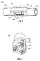
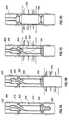
- FIGS. 1-3An expander tool usable to expand solid or slotted tubulars is illustrated in FIGS. 1-3.
- the expansion tool 100has a body 102 which is hollow and generally tubular with connectors 104 and 106 for connection to other components (not shown) of a downhole assembly.
- FIGS. 1 and 2are perspective side views of the expansion tool and
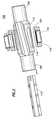
- FIG. 3is an exploded view thereof.
- the end connectors 104 and 106are of a reduced diameter (compared to the outside diameter of the longitudinally central body part 108 of the tool 100 ), and together with three longitudinal flutes 110 on the central body part 108 , allow the passage of fluids between the outside of the tool 100 and the interior of a tubular therearound (not shown).
- the central body part 108has three lands 112 defined between the three flutes 110 , each land 112 being formed with a respective recess 114 to hold a respective expandable member 116 .
- Each of the recesses 114has parallel sides and extends radially from the radially perforated tubular core 115 of the tool 100 to the exterior of the respective land 112 .
- Each of the mutually identical rollers 116is near-cylindrical and slightly barreled.
- Each of the rollers 116is mounted by means of a bearing 118 at each end of the respective roller for rotation about a respective rotation axis which is parallel to the longitudinal axis of the tool 100 and radially offset therefrom at 120-degree mutual circumferential separations around the central body 108 .
- the bearings 418are formed as integral end members of radially slidable pistons 120 , one piston 120 being slidably sealed within each radially extended recess 114 .
- the inner end of each piston 120(FIG. 2) is exposed to the pressure of fluid within the hollow core of the tool 100 by way of the radial perforations in the tubular core 115 .
- expandable sand screenis useful in wells to eliminate the annular area formed between a conventional screen and a casing, its use can add yet another step to the completion of a well and requires at least an additional trip into the well with a run-in string of tubular in order to expand the screen. Because the various completion operations described are performed in separate and time consuming steps, there is a need for well completion apparatus and methods using expandable well screen that combines various completion steps and decreases time and expense associated with completing a well.
- apparatus and methodsare provided for completing a wellbore using expandable sand screen.
- An apparatusincluding a section of expandable sand screen, and an expanding member is disposed in the wellbore on a tubular run-in string. Thereafter, the expandable sand screen is expanded in a producing area of the wellbore.
- the apparatusincludes a packer above and below the section of expandable sand screen to isolate the wellbore above and below the sand screen.
- the apparatusincludes a perforating assembly which is utilized to form perforations in a wellbore casing and thereafter, the expandable sand screen is expanded in the area of the perforations.
- wellbore casingis perforated and subsequently treated with fracturing materials before a section of sand screen is expanded in the area of the perforations.
- an annular area between the unexpanded sand screen and perforated casingis filled with a slurry of gravel. Thereafter, the expandable sand screen is expanded in the area of the perforations and the gravel is compressed between the sand screen and the perforated casing wall.
- a methodincluding the steps of running an apparatus into a wellbore, anchoring a section of well screen in the wellbore, perforating the wellbore, disposing the sand screen in the wellbore in the area of the perforations and expanding the sand screen in the area of the perforations.
- FIG. 1is a perspective view of an expander tool.
- FIG. 2is a perspective view of an expander tool.
- FIG. 3is an exploded view of the expander tool.
- FIG. 4Ais a section view of a wellbore with an apparatus of the present invention disposed therein.
- FIG. 4Bis a section view of the wellbore with the lower packer of the apparatus set.
- FIG. 4Cis a section view of the wellbore illustrating the apparatus after perforations have been formed in wellbore casing with perforating guns.
- FIG. 4Dillustrates the apparatus in the wellbore after the apparatus has been adjusted axially to place the perforations in the casing between the upper and lower packers of the apparatus.
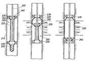
- FIG. 4Eillustrates an expandable sand screen portion of the apparatus being expanded by a cone member disposed at a bottom end of the run-in string.
- FIG. 4Fillustrates the apparatus with the expandable sand screen expanded and the upper packer set.
- FIG. 4Gillustrates the apparatus with the expanding cone having disconnected from the run-in string and retained in the lower packer.
- FIG. 4Hillustrates the apparatus of the present invention with the expandable sand screen fully expanded, both packers set and production tubing in fluid communication with the perforated portion of the well.
- FIG. 5Ais a section view of a wellbore illustrating another embodiment of the invention disposed therein.
- FIG. 5Bis a section view of the apparatus in a wellbore with an expandable sand screen partially expanded into contact with casing therearound.
- FIG. 5Cis a section view of the apparatus in a wellbore with the expandable sand screen fully expanded.
- FIG. 5Dis a section view of the wellbore showing a cone member 240 disposed on a lower packer.
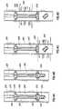
- FIGS. 6A-6Hare section views of another embodiment of the invention disposed in a wellbore utilizing an expander tool to expand the diameter of a section of expandable sand screen.
- FIGS. 7A-7Dillustrates another embodiment of the invention in a wellbore whereby casing is perforated and a formation therearound is treated prior to a section of expandable sand screen being expanded.
- FIGS. 8A-8Dillustrate another embodiment of the invention disposed in a wellbore whereby gravel is inserted in an annular area between the sand screen and the casing and then the expandable sand screen is expanded.
- FIG. 4Ais a section view of a wellbore 205 with an apparatus 200 of the present invention disposed therein on a run-in string of tubulars 225 having a reduced diameter portion 226 .
- the wellboreis typical of one drilled to access a hydrocarbon-bearing formation and the wellbore is lined with steel casing 210 . While the apparatus and wellbore disclosed and illustrated are for use with hydrocarbon wells like oil and gas wells, the methods and apparatus are useful in any wellbore, even those not lined with casing.
- the apparatus 200includes an expandable sand screen 220 coaxially disposed around the reduced diameter portion 226 of the run-in string.
- the expandable sand screen utilized in the apparatus of the inventiontypically includes a perforated base pipe, a filtration medium disposed around the base pipe and an expandable protective shroud, all of which are expandable.
- packer 230 , 235At each end of the screen 220 is packer 230 , 235 .
- a perforating gun assembly 250is temporarily attached at a lower end of the lower packer 235 and an expansion cone 240 is temporarily attached on a lower end of the run-in string 225 .
- the upper packer 230is typically referred to as a production packer and includes an element to extend radially outward to contact the casing when the packer is remotely set. Packer 230 also includes a central bore to receive production string of tubulars and to seal the connection therewith.
- the upper packer 230is typically set after the lower packer 235 and is set with pressure developed thereabove.
- the lower packer 235is a dual grip, mechanically set packer which resists axial movement in both directions.
- the lower packeris typically set using rotation and weight to manipulate a slip assembly therearound.
- the cone member 240is temporarily connected at the bottom end of the run-in string 225 and includes a cone-shaped surface 242 sloped in the direction of the bottom end of the screen 220 . As illustrated in FIG. 4A, the cone member rests in a central bore of the lower packer. The purpose of the cone member 240 is to expand the inner and outer diameter of the expandable screen 220 as the cone is urged through the sand screen as will be described herein. In the embodiment illustrated in FIG. 4A, the cone member is detachable from the run-in string after the expandable sand screen has been expanded. In one embodiment, a shearable connection between the cone member and the run-in string is caused to fail and the cone falls back to rest in the lower packer 235 .
- the perforating gun assembly 250is typical of tubing conveyed perforating assemblies that include shaped charges designed to penetrate steel casing and provide a fluid path between the formation and the wellbore.
- the assembly 250includes a tubing release member (not shown) disposed between the gun and the run-in string.
- the operation of perforating gun assembly 250is well known in the art and the assembly can be fired remotely either by electrical or physical methods.
- the tubing releaseis constructed and arranged to detach the perforating gun assembly from the run-in string as the gun fires and perforates the casing therearound.
- the gun assemblydislocates itself from the apparatus in order to avoid any interference with other components or any other perforated zones in the well.
- FIGS. 4B-4Hillustrate various steps involved in utilizing the apparatus 200 of the present invention in order to complete a well.
- FIG. 1Bis a section view of the apparatus illustrating the lower packer 230 in a set position whereby axial movement of the apparatus 200 within the wellbore 205 is restricted.
- the lower packer 235is mechanically set, typically by rotating the runin string 225 and the apparatus 200 within the wellbore. In addition to fixing the apparatus 200 in the wellbore, the packer 235 is set in order to protect the upper portion of the apparatus from the discharging perforating gun assembly 250 therebelow.
- FIG. 1Bis a section view of the apparatus illustrating the lower packer 230 in a set position whereby axial movement of the apparatus 200 within the wellbore 205 is restricted.
- the lower packer 235is mechanically set, typically by rotating the runin string 225 and the apparatus 200 within the wellbore.
- the packer 235is set in order to protect the upper portion of the apparatus from the discharging
- FIG. 4Cis a section view of the apparatus 200 in the wellbore 205 illustrating the perforating gun assembly 250 having discharged to form a plurality of perforations 255 in the steel casing 250 and the formation therearound. Also illustrated in FIG. 4C is the detachable feature of the perforating gun assembly 250 whereby, after the assembly is discharged it is also mechanically disconnected from the apparatus 200 to fall from the lower packer 235 .
- FIG. 4Dis a section view of the apparatus 200 after the apparatus has been axially moved in the wellbore to place the newly formed perforations 255 between the upper 230 and lower 235 packers.
- the lower packer 235is un-set after the perforations 255 are formed and the apparatus 200 and run-in string 225 is lowered in the wellbore to center the perforations 255 between the packers 230 , 235 . Thereafter, the lower packer 235 is re-set to again axially fix the apparatus in the wellbore 205 .
- FIG. 4Eis a section view showing the apparatus 200 in the wellbore with the expandable sand screen 220 being expanded to substantially the same outer diameter as the inner diameter of the wellbore casing 210 .
- the run-in string 225is pulled upwards in the wellbore and the cone member 240 is forced upward in the apparatus 200 while the expandable sand screen 220 is anchored in place by the lower packer 235 therebelow.
- the expandable sand screen 220is expanded.
- the screenis shown as expanded to an inner diameter well past the outer diameter of the cone.
- the Figureintentionally exaggerates the relative expansion of the screen.
- use of the screencan be expanded to substantially eliminate the annular area between the screen 220 and the casing 210 .
- FIG. 4Fillustrates the apparatus 200 with the expandable sand screen 220 completely expanded along its length in the areas of the perforations 255 , thereby eliminating any annular area formed between the sand screen 220 and the wellbore casing 210 .
- the upper packer 230is hydraulically set.
- a ball 241visible in FIG. 4G
- FIG. 4Ga ball 241 is dropped through the run-in string and into a receiving seat in the cone member 240 after the screen 220 is completely expanded and the cone 240 is in the position shown in FIG. 3 F.
- fluid pressureis increased to a predetermined level and the upper packer 230 is set.
- a shearing mechanism(not shown) between the cone member 240 and the run-in string 225 is caused to fail, permitting the cone member to fall down to the lower packer 235 where it is held therein.
- the shearing mechanismmay be actuated with physical force by pulling the run-in string 225 upwards or simply by pressure.
- the upper packeris set with a pressure of 2,500 psi and the shearable connection between the packer and the cone fails at about 4,000 psi.
- FIG. 4Gis a section view of the wellbore 205 illustrating both packers 230 , 235 actuated with the expandable sand screen 220 expanded therebetween and the cone member 240 located in the center of the lower packer 235 .
- FIG. 4Hillustrates another string of tubulars 260 having been attached to the upper packer 230 .
- the string of tubularsmay serve as protection tubing forming a sealed arrangement with the center of the upper packer 230 .
- FIG. 5Aillustrates another embodiment of the invention illustrating an apparatus 300 on a string of tubulars 325 .
- a cone member 340is disposed on the run-in string at the upper end of a section of expandable sand screen 320 .
- a sloped surface 342decreases the diameter of the cone member in the direction of the sand screen 320 , whereby the cone 340 is arranged to expand the expandable screen 320 in a top-down fashion.
- the apparatus of FIG. 5Aincludes an upper, hydraulically set packer 230 , a lower, mechanically set packer 235 and a perforating gun assembly 250 disposed at a lower end of the lower packer 235 .
- the lower packer 235can be set using rotation and thereafter, the perforating gun assembly 250 can be fired by remote means, thereby forming a plurality of perforations 255 around the casing 210 and into the formation therearound.
- the perforation gun assemblyincludes a release mechanism causing the assembly to drop from the apparatus after firing. Thereafter, the lower packer 235 is un-set and the apparatus 300 is moved axially in the wellbore 205 to center the newly formed perforations 255 between the upper and lower packers 230 , 235 .
- FIG. 5Billustrates the apparatus 300 in the wellbore 205 and specifically illustrates the expandable sand screen 220 partially expanded by the downward movement of the cone member 340 along the screen which is fixed in place by the bi-directional lower packer 235 which has been re-set.
- the cone member 340moves downward to completely expand the sand screen 220 in the area of the perforations 250 and thereafter, the cone member 240 , as illustrated in FIG. 5D latches into the lower packer 235 .
- upper packer 230is set hydraulically, typically with a source of fluid from the run-in string 225 which is placed in communication with the packer by the use of some selectively operable valving arrangement between the string and the packer. Thereafter, the run-in string may be removed by shearing the cone 340 from the string 225 and a string of production tubing (not shown) can be attached to the upper packer 230 and the well can be completed for production.
- FIG. 6Ais a section view illustrating another embodiment of the invention whereby an apparatus 400 includes the expander tool 100 as illustrated in FIGS. 1-3.
- the apparatus 400includes upper 230 and lower 235 packers with a section of expandable sand screen 420 disposed therebetween.
- the expander tool 100is constructed and arranged to expand the expandable wellscreen through the use of roller members which are hydraulically actuated by fluid power provided in the tubular string 225 as discussed in connection with FIGS. 1-3.
- a perforating gun assembly 250is temporarily connected at a lower end of the bottom packer 235 .
- FIG. 6Billustrates the apparatus 400 with the lower packer 235 mechanically actuated in the wellbore 205 to fix the apparatus 400 therein.
- FIG. 6Cillustrates the apparatus 400 after the perforating gun assembly 250 has been discharged to form perforations 255 through the wellbore casing 210 and into the formation.
- the gun assembly 250With its discharge, the gun assembly 250 has detached from the apparatus 400 to fall to the bottom of the wellbore 205 .
- the lower packer 235is un-set and then re-set after the apparatus 400 is adjusted axially in the wellbore 210 to center the newly formed perforations 255 between the upper 230 and lower 235 packers as illustrated in FIG. 6 D.
- FIG. 6Eshows the apparatus 400 in the wellbore after the expanding tool 100 has been actuated by fluid power and the actuated expanding tool 100 is urged upward in the wellbore 205 thereby expanding the expandable sand screen 420 .
- the run-in string 425 bearing the expander tool 100is pulled upwards and rotated as the rollers on the expander force the wall of the screen past its elastic limit. In this manner, substantially the entire length of the sand screen 420 can be expanded circumferentially.
- FIG. 6Fis a section view of the wellbore 205 illustrating the sand screen 420 expanded in the area of the perforations 255 and the expanding tool 100 at the top of the sand screen 420 .
- FIG. 6Galso shows the upper packer 230 having been set hydraulically, typically by pressurized fluid in the run-in string passing into the packer 230 via a selectively operable valve member (not shown) and the alignment of apertures in the run-in string 425 and the packer 230 .
- FIG. 6Hillustrates the apparatus 400 with the run-in string 225 and expanding tool 100 having been removed and production tubing 460 attached to the upper packer 230 and creating a seal therebetween.
- FIGS. 6A-6Hillustrate the apparatus 400 with the expansion tool 100 arranged to increase the diameter of the expandable sand screen 420 in a bottom-up fashion
- the apparatuscan also be used whereby the expansion tool 100 operates in a top-down fashion.
- the expansion tool 100can be run into the well on a string of coiled tubing with a mud motor disposed on the tubing adjacent the expansion tool in order to provide rotation thereto.
- mud motorsoperate with a flow of fluid and translate the flow into rotational force.
- a fluid powered tractorcan be used in the run-in string to urge the actuated expansion tool axially in the wellbore from a first to a second end of the expandable screen.
- Tractorslike the expansion tool 100 have a plurality of radially extendable members which can be actuated against the inner wall of a tubular around the tractor to impart axial movement to the tractor and other components mechanically attached thereto.
- the use of tractorsis especially advantageous in a vertical with lateral wellbores. By properly sizing the body and extendable members of a tractor, the tractor can also provide axial movement in an area of a wellbore previously expanded.
- FIG. 7Aillustrates another embodiment of the invention showing an apparatus 500 disposed in a cased wellbore 205 .
- the apparatusincludes a section of expandable sand screen 520 , upper and lower packers 230 , 235 , as well as a run-in string 525 with a cone member 242 disposed at a lower end thereof and a perforating gun assembly 250 with a temporary mechanical connection disposed on the lower packer 235 .
- the apparatus 500includes a cross-over tool 505 constructed and arranged to pass fluid from the inside of the tubular run-in string 525 to the annular area 510 created between the outside of the expandable sand screen 520 and the inside surface of the wellbore casing 210 .
- FIG. 7Bis a section view of the apparatus 500 after the perforating gun assembly 250 has discharged and formed a plurality of perforations 255 through the wellbore casing and into the formation therearound.
- the apparatus 500has been axially re-positioned within the wellbore 205 whereby the newly formed perforations 255 are centered between the upper 230 and lower packers 235 which are set.
- FIG. 7Cillustrates the apparatus 500 with arrows 501 added to depict the flow of fluid in an injection operation which is performed after the perforations 255 are formed in the casing 210 .
- chemicals or surfactantsare injected through the run-in string 525 to exit and penetrate the formation via the perforations 255 between the upper 230 and lower 235 packers.
- return fluidpasses back up to the surface through the annular area 510 between the run-in string 525 and the casing 210 above the upper packer 230 .
- FIG. 7Dillustrates the apparatus 500 after the cone member 242 (not shown) has been urged upward, thereby expanding the expandable sand screen 520 in the area of the perforations 255 .
- the cone memberhas been removed and the run-in string 525 has been replaced by a production string of tubulars 526 installed in a sealing relationship with an inner bore of upper packer 230 .
- the wellboreis perforated, treated and the expandable sand screen 520 is expanded to substantially the diameter of the casing 210 in a single trip.
- FIG. 8Aillustrates another embodiment of the invention and includes a wellbore 205 having steel casing 210 therearound and an apparatus 600 disposed in the wellbore.
- the apparatusincludes an upper 230 and lower 235 packer with a section of expandable wellscreen 620 disposed therebetween.
- the apparatusalso includes a cone member 340 disposed at a lower end thereof and a perforating gun assembly 250 temporarily connected to a lower end of the lower packer 235 .
- the upper packer 230also operates as a cross-over tool 605 .
- the cross-over toolis capable of passing a gravel containing slurry from the tubular run-in string 625 to an annular area 610 formed between the expandable sand screen 620 and the casing 210 .
- FIG. 8Billustrates the apparatus 600 in the wellbore after the perforating gun assembly 250 has been discharged to form a plurality of perforations 255 in the casing 210 and the formation therearound and after the apparatus 600 has been repositioned axially in the wellbore 205 to center the newly formed perforations 255 between the upper 230 and lower 235 packers. Also in FIG. 8B, the perforating gun assembly 250 has fallen away from the apparatus 600 .
- FIG. 8Billustrates the apparatus 600 in the wellbore after the perforating gun assembly 250 has been discharged to form a plurality of perforations 255 in the casing 210 and the formation therearound and after the apparatus 600 has been repositioned axially in the wellbore 205 to center the newly formed perforations 255 between the upper
- FIG. 8Cillustrates sized gravel 621 having been disposed in the annulus 610 and in the perforations between the expandable sand screen 620 and the casing 210 .
- This type of gravel packis well known to those skilled in the art and the gravel is typically injected in a slurry of fluid with the fluid thereafter being removed from the gravel through a return suction created in the run-in tubular 625 or the annulus between the run-in string and the wellbore.
- FIG. 8Dis a section view of the apparatus 600 after the cone member 340 has been urged upwards to expand the expandable sand screen 620 which is fixed in the well by the lower, mechanical packer 235 .
- the cone member 340has been removed from the wellbore 205 and the run-in string 625 has been replaced by production tubing 626 which is installed in a sealing relationship with the inner bore of upper packer 230 .
- the expandable sand screen 620is used in conjunction with the gravel pack to complete a well after perforations have been formed. The entire aperture is performed in a single trip into the well.
- the method and apparatuscan also be used to first chemically treat a well and then to perform the gravel pack prior to expanding the screen section.
- the inventionpermits various wellbore activities related to the completion to be completed in a single trip.
Landscapes
- Mining & Mineral Resources (AREA)
- Engineering & Computer Science (AREA)
- Life Sciences & Earth Sciences (AREA)
- Geology (AREA)
- Geochemistry & Mineralogy (AREA)
- Environmental & Geological Engineering (AREA)
- Fluid Mechanics (AREA)
- General Life Sciences & Earth Sciences (AREA)
- Physics & Mathematics (AREA)
- Dispersion Chemistry (AREA)
- Chemical & Material Sciences (AREA)
- Consolidation Of Soil By Introduction Of Solidifying Substances Into Soil (AREA)
- Investigation Of Foundation Soil And Reinforcement Of Foundation Soil By Compacting Or Drainage (AREA)
- Separation Of Solids By Using Liquids Or Pneumatic Power (AREA)
- Revetment (AREA)
- Other Liquid Machine Or Engine Such As Wave Power Use (AREA)
- Filtration Of Liquid (AREA)
- Farming Of Fish And Shellfish (AREA)
- Agricultural Chemicals And Associated Chemicals (AREA)
Abstract
Description
Claims (16)
Priority Applications (7)
| Application Number | Priority Date | Filing Date | Title |
|---|---|---|---|
| US09/849,624US6510896B2 (en) | 2001-05-04 | 2001-05-04 | Apparatus and methods for utilizing expandable sand screen in wellbores |
| GB0323116AGB2391574B (en) | 2001-05-04 | 2002-05-01 | Apparatus and method for utilising expandable sand screen in wellbores |
| PCT/GB2002/002005WO2002090712A1 (en) | 2001-05-04 | 2002-05-01 | Apparatus and method for utilising expandable sand screen in wellbores |
| CA2638790ACA2638790C (en) | 2001-05-04 | 2002-05-01 | Apparatus and method for utilising expandable sand screen in wellbores |
| CA002444086ACA2444086C (en) | 2001-05-04 | 2002-05-01 | Apparatus and method for utilising expandable sand screen in wellbores |
| CA2707740ACA2707740C (en) | 2001-05-04 | 2002-05-01 | Apparatus and method for utilising expandable sand screen in wellbores |
| US10/347,527US6832649B2 (en) | 2001-05-04 | 2003-01-17 | Apparatus and methods for utilizing expandable sand screen in wellbores |
Applications Claiming Priority (1)
| Application Number | Priority Date | Filing Date | Title |
|---|---|---|---|
| US09/849,624US6510896B2 (en) | 2001-05-04 | 2001-05-04 | Apparatus and methods for utilizing expandable sand screen in wellbores |
Related Child Applications (1)
| Application Number | Title | Priority Date | Filing Date |
|---|---|---|---|
| US10/347,527ContinuationUS6832649B2 (en) | 2001-05-04 | 2003-01-17 | Apparatus and methods for utilizing expandable sand screen in wellbores |
Publications (2)
| Publication Number | Publication Date |
|---|---|
| US20020162664A1 US20020162664A1 (en) | 2002-11-07 |
| US6510896B2true US6510896B2 (en) | 2003-01-28 |
Family
ID=25306147
Family Applications (2)
| Application Number | Title | Priority Date | Filing Date |
|---|---|---|---|
| US09/849,624Expired - LifetimeUS6510896B2 (en) | 2001-05-04 | 2001-05-04 | Apparatus and methods for utilizing expandable sand screen in wellbores |
| US10/347,527Expired - LifetimeUS6832649B2 (en) | 2001-05-04 | 2003-01-17 | Apparatus and methods for utilizing expandable sand screen in wellbores |
Family Applications After (1)
| Application Number | Title | Priority Date | Filing Date |
|---|---|---|---|
| US10/347,527Expired - LifetimeUS6832649B2 (en) | 2001-05-04 | 2003-01-17 | Apparatus and methods for utilizing expandable sand screen in wellbores |
Country Status (4)
| Country | Link |
|---|---|
| US (2) | US6510896B2 (en) |
| CA (3) | CA2444086C (en) |
| GB (1) | GB2391574B (en) |
| WO (1) | WO2002090712A1 (en) |
Cited By (52)
| Publication number | Priority date | Publication date | Assignee | Title |
|---|---|---|---|---|
| US20030106697A1 (en)* | 2001-05-04 | 2003-06-12 | Weatherford/Lamb, Inc. | Apparatus and methods for utilizing expandable sand screen in wellbores |
| US20030227170A1 (en)* | 2002-06-10 | 2003-12-11 | Weatherford/Lamb, Inc. | Pre-expanded connector for expandable downhole tubulars |
| US20040043544A1 (en)* | 2002-04-25 | 2004-03-04 | Hitachi Kokusai Electric Inc. | Manufacturing method of semiconductor device and substrate processing apparatus |
| US20040045707A1 (en)* | 2002-09-11 | 2004-03-11 | Nguyen Philip D. | Method for determining sand free production rate and simultaneously completing a borehole |
| US20040065445A1 (en)* | 2001-05-15 | 2004-04-08 | Abercrombie Simpson Neil Andrew | Expanding tubing |
| US6719064B2 (en)* | 2001-11-13 | 2004-04-13 | Schlumberger Technology Corporation | Expandable completion system and method |
| US20040162224A1 (en)* | 2002-04-18 | 2004-08-19 | Nguyen Philip D. | Method of tracking fluids produced from various zones in subterranean well |
| US20050000697A1 (en)* | 2002-07-06 | 2005-01-06 | Abercrombie Simpson Neil Andrew | Formed tubulars |
| US6854521B2 (en)* | 2002-03-19 | 2005-02-15 | Halliburton Energy Services, Inc. | System and method for creating a fluid seal between production tubing and well casing |
| US20050045326A1 (en)* | 2003-08-26 | 2005-03-03 | Nguyen Philip D. | Production-enhancing completion methods |
| US20050089631A1 (en)* | 2003-10-22 | 2005-04-28 | Nguyen Philip D. | Methods for reducing particulate density and methods of using reduced-density particulates |
| US20050139394A1 (en)* | 2003-12-29 | 2005-06-30 | Noble Drilling Services Inc. | Expandable screen utilizing near neutrally-buoyant particles outside of the screen |
| US20050173109A1 (en)* | 2001-09-26 | 2005-08-11 | Weatherford/Lamb, Inc. | Profiled recess for instrumented expandable components |
| US20050252657A1 (en)* | 2004-05-13 | 2005-11-17 | Schlumberger Technology Corporation | Method and Apparatus to Isolate Fluids During Gravel Pack Operations |
| US20050257929A1 (en)* | 2002-01-08 | 2005-11-24 | Halliburton Energy Services, Inc. | Methods and compositions for consolidating proppant in subterranean fractures |
| US20060006647A1 (en)* | 2004-07-07 | 2006-01-12 | Hashem Ghazi J | Hybrid threaded connection for expandable tubulars |
| US20060076138A1 (en)* | 2004-10-08 | 2006-04-13 | Dusterhoft Ronald G | Method and composition for enhancing coverage and displacement of treatment fluids into subterranean formations |
| US20060096761A1 (en)* | 2004-11-10 | 2006-05-11 | Weatherford/Lamb, Inc. | Slip on screen with expanded base pipe |
| US20060124303A1 (en)* | 2004-12-12 | 2006-06-15 | Halliburton Energy Services, Inc. | Low-quality particulates and methods of making and using improved low-quality particulates |
| US20060219408A1 (en)* | 2005-03-29 | 2006-10-05 | Halliburton Energy Services, Inc. | Methods for controlling migration of particulates in a subterranean formation |
| US20060219405A1 (en)* | 2005-03-29 | 2006-10-05 | Halliburton Energy Services, Inc. | Method of stabilizing unconsolidated formation for sand control |
| US20060240995A1 (en)* | 2005-04-23 | 2006-10-26 | Halliburton Energy Services, Inc. | Methods of using resins in subterranean formations |
| US20070000664A1 (en)* | 2005-06-30 | 2007-01-04 | Weatherford/Lamb, Inc. | Axial compression enhanced tubular expansion |
| US20070007009A1 (en)* | 2004-01-05 | 2007-01-11 | Halliburton Energy Services, Inc. | Methods of well stimulation and completion |
| US7168485B2 (en) | 2001-01-16 | 2007-01-30 | Schlumberger Technology Corporation | Expandable systems that facilitate desired fluid flow |
| US20070035130A1 (en)* | 2005-08-11 | 2007-02-15 | Weatherford/Lamb, Inc. | Reverse sliding seal for expandable tubular connections |
| US20070114032A1 (en)* | 2005-11-22 | 2007-05-24 | Stegent Neil A | Methods of consolidating unconsolidated particulates in subterranean formations |
| US20070179065A1 (en)* | 2004-03-03 | 2007-08-02 | Halliburton Energy Services, Inc. | Resin compositions and methods of using such resin compositions in subterranean applications |
| US20070187097A1 (en)* | 2006-02-10 | 2007-08-16 | Weaver Jimmie D | Consolidating agent emulsions and associated methods |
| US20080006406A1 (en)* | 2006-07-06 | 2008-01-10 | Halliburton Energy Services, Inc. | Methods of enhancing uniform placement of a resin in a subterranean formation |
| US20080006405A1 (en)* | 2006-07-06 | 2008-01-10 | Halliburton Energy Services, Inc. | Methods and compositions for enhancing proppant pack conductivity and strength |
| US20080011478A1 (en)* | 2005-07-11 | 2008-01-17 | Welton Thomas D | Methods and Compositions for Controlling Formation Fines and Reducing Proppant Flow-Back |
| US20080060809A1 (en)* | 2004-09-09 | 2008-03-13 | Parker Mark A | High Porosity Fractures and Methods of Creating High Porosity Fractures |
| US20080115692A1 (en)* | 2006-11-17 | 2008-05-22 | Halliburton Energy Services, Inc. | Foamed resin compositions and methods of using foamed resin compositions in subterranean applications |
| US20080115944A1 (en)* | 2006-11-22 | 2008-05-22 | Weatherford/Lamb, Inc. | Well barrier apparatus and associated methods |
| US20080135251A1 (en)* | 2006-02-10 | 2008-06-12 | Halliburton Energy Services, Inc. | Compositions and applications of resins in treating subterranean formations |
| US20080156499A1 (en)* | 2007-01-03 | 2008-07-03 | Richard Lee Giroux | System and methods for tubular expansion |
| US20080196897A1 (en)* | 2007-02-15 | 2008-08-21 | Halliburton Energy Services, Inc. | Methods of completing wells for controlling water and particulate production |
| US7541318B2 (en) | 2004-05-26 | 2009-06-02 | Halliburton Energy Services, Inc. | On-the-fly preparation of proppant and its use in subterranean operations |
| US20090151943A1 (en)* | 2006-02-10 | 2009-06-18 | Halliburton Energy Services, Inc. | Aqueous-based emulsified consolidating agents suitable for use in drill-in applications |
| US20100032167A1 (en)* | 2008-08-08 | 2010-02-11 | Adam Mark K | Method for Making Wellbore that Maintains a Minimum Drift |
| US7712531B2 (en) | 2004-06-08 | 2010-05-11 | Halliburton Energy Services, Inc. | Methods for controlling particulate migration |
| US20100132943A1 (en)* | 2004-02-10 | 2010-06-03 | Nguyen Philip D | Resin Compositions and Methods of Using Resin Compositions to Control Proppant Flow-Back |
| US20100175895A1 (en)* | 2007-06-26 | 2010-07-15 | Paul David Metcalfe | Permeability Modification |
| US7762329B1 (en) | 2009-01-27 | 2010-07-27 | Halliburton Energy Services, Inc. | Methods for servicing well bores with hardenable resin compositions |
| US7766099B2 (en) | 2003-08-26 | 2010-08-03 | Halliburton Energy Services, Inc. | Methods of drilling and consolidating subterranean formation particulates |
| US20110214855A1 (en)* | 2001-01-16 | 2011-09-08 | Barrie Hart | Expandable Device for Use in a Well Bore |
| US8167045B2 (en) | 2003-08-26 | 2012-05-01 | Halliburton Energy Services, Inc. | Methods and compositions for stabilizing formation fines and sand |
| USRE45011E1 (en) | 2000-10-20 | 2014-07-15 | Halliburton Energy Services, Inc. | Expandable tubing and method |
| US9677387B2 (en) | 2012-02-23 | 2017-06-13 | Schlumberger Technology Corporation | Screen assembly |
| US10677029B2 (en) | 2015-03-30 | 2020-06-09 | 925599 Alberta Ltd. | Method and system for servicing a well |
| WO2021118657A1 (en)* | 2019-12-10 | 2021-06-17 | Halliburton Energy Services, Inc. | Completion systems and methods to complete a well |
Families Citing this family (68)
| Publication number | Priority date | Publication date | Assignee | Title |
|---|---|---|---|---|
| US7121352B2 (en) | 1998-11-16 | 2006-10-17 | Enventure Global Technology | Isolation of subterranean zones |
| US7231985B2 (en) | 1998-11-16 | 2007-06-19 | Shell Oil Company | Radial expansion of tubular members |
| US6823937B1 (en)* | 1998-12-07 | 2004-11-30 | Shell Oil Company | Wellhead |
| US6557640B1 (en) | 1998-12-07 | 2003-05-06 | Shell Oil Company | Lubrication and self-cleaning system for expansion mandrel |
| AU2001269810B2 (en) | 1998-11-16 | 2005-04-07 | Shell Oil Company | Radial expansion of tubular members |
| US7357188B1 (en) | 1998-12-07 | 2008-04-15 | Shell Oil Company | Mono-diameter wellbore casing |
| US7603758B2 (en) | 1998-12-07 | 2009-10-20 | Shell Oil Company | Method of coupling a tubular member |
| US7185710B2 (en) | 1998-12-07 | 2007-03-06 | Enventure Global Technology | Mono-diameter wellbore casing |
| US7552776B2 (en) | 1998-12-07 | 2009-06-30 | Enventure Global Technology, Llc | Anchor hangers |
| GB2344606B (en) | 1998-12-07 | 2003-08-13 | Shell Int Research | Forming a wellbore casing by expansion of a tubular member |
| US7195064B2 (en) | 1998-12-07 | 2007-03-27 | Enventure Global Technology | Mono-diameter wellbore casing |
| US7363984B2 (en) | 1998-12-07 | 2008-04-29 | Enventure Global Technology, Llc | System for radially expanding a tubular member |
| US6758278B2 (en) | 1998-12-07 | 2004-07-06 | Shell Oil Company | Forming a wellbore casing while simultaneously drilling a wellbore |
| AU770359B2 (en) | 1999-02-26 | 2004-02-19 | Shell Internationale Research Maatschappij B.V. | Liner hanger |
| US7055608B2 (en) | 1999-03-11 | 2006-06-06 | Shell Oil Company | Forming a wellbore casing while simultaneously drilling a wellbore |
| US7350563B2 (en) | 1999-07-09 | 2008-04-01 | Enventure Global Technology, L.L.C. | System for lining a wellbore casing |
| AU783245B2 (en) | 1999-11-01 | 2005-10-06 | Shell Internationale Research Maatschappij B.V. | Wellbore casing repair |
| US7234531B2 (en) | 1999-12-03 | 2007-06-26 | Enventure Global Technology, Llc | Mono-diameter wellbore casing |
| CA2416573A1 (en) | 2000-09-18 | 2002-03-21 | Shell Canada Ltd | Liner hanger with sliding sleeve valve |
| US7100685B2 (en) | 2000-10-02 | 2006-09-05 | Enventure Global Technology | Mono-diameter wellbore casing |
| US6725934B2 (en)* | 2000-12-21 | 2004-04-27 | Baker Hughes Incorporated | Expandable packer isolation system |
| US7410000B2 (en) | 2001-01-17 | 2008-08-12 | Enventure Global Technology, Llc. | Mono-diameter wellbore casing |
| WO2003004820A2 (en) | 2001-07-06 | 2003-01-16 | Enventure Global Technology | Liner hanger |
| GB2394979B (en) | 2001-07-06 | 2005-11-02 | Eventure Global Technology | Liner hanger |
| US7258168B2 (en) | 2001-07-27 | 2007-08-21 | Enventure Global Technology L.L.C. | Liner hanger with slip joint sealing members and method of use |
| GB2396639B (en) | 2001-08-20 | 2006-03-08 | Enventure Global Technology | An apparatus for forming a wellbore casing by use of an adjustable tubular expansion cone |
| KR100378586B1 (en)* | 2001-08-29 | 2003-04-03 | 테커스 (주) | Anti Keylog method of ActiveX base and equipment thereof |
| WO2004094766A2 (en) | 2003-04-17 | 2004-11-04 | Enventure Global Technology | Apparatus for radially expanding and plastically deforming a tubular member |
| CA2459910C (en) | 2001-09-07 | 2010-04-13 | Enventure Global Technology | Adjustable expansion cone assembly |
| US7513313B2 (en) | 2002-09-20 | 2009-04-07 | Enventure Global Technology, Llc | Bottom plug for forming a mono diameter wellbore casing |
| WO2004081346A2 (en) | 2003-03-11 | 2004-09-23 | Enventure Global Technology | Apparatus for radially expanding and plastically deforming a tubular member |
| AU2002343651A1 (en) | 2001-11-12 | 2003-05-26 | Enventure Global Technology | Collapsible expansion cone |
| US7290605B2 (en) | 2001-12-27 | 2007-11-06 | Enventure Global Technology | Seal receptacle using expandable liner hanger |
| GB0131019D0 (en)* | 2001-12-27 | 2002-02-13 | Weatherford Lamb | Bore isolation |
| WO2003086675A2 (en) | 2002-04-12 | 2003-10-23 | Enventure Global Technology | Protective sleeve for threaded connections for expandable liner hanger |
| WO2003089161A2 (en) | 2002-04-15 | 2003-10-30 | Enventure Global Technlogy | Protective sleeve for threaded connections for expandable liner hanger |
| WO2004018823A2 (en) | 2002-08-23 | 2004-03-04 | Enventure Global Technology | Interposed joint sealing layer method of forming a wellbore casing |
| WO2004027786A2 (en) | 2002-09-20 | 2004-04-01 | Enventure Global Technology | Protective sleeve for expandable tubulars |
| WO2004018824A2 (en) | 2002-08-23 | 2004-03-04 | Enventure Global Technology | Magnetic impulse applied sleeve method of forming a wellbore casing |
| US6732806B2 (en)* | 2002-01-29 | 2004-05-11 | Weatherford/Lamb, Inc. | One trip expansion method and apparatus for use in a wellbore |
| MXPA04007922A (en) | 2002-02-15 | 2005-05-17 | Enventure Global Technology | Mono-diameter wellbore casing. |
| US6899182B2 (en)* | 2002-05-08 | 2005-05-31 | Baker Hughes Incorporated | Method of screen or pipe expansion downhole without addition of pipe at the surface |
| US7360591B2 (en) | 2002-05-29 | 2008-04-22 | Enventure Global Technology, Llc | System for radially expanding a tubular member |
| GB2418943B (en) | 2002-06-10 | 2006-09-06 | Enventure Global Technology | Mono Diameter Wellbore Casing |
| AU2003265452A1 (en) | 2002-09-20 | 2004-04-08 | Enventure Global Technology | Pipe formability evaluation for expandable tubulars |
| GB2410280B (en) | 2002-09-20 | 2007-04-04 | Enventure Global Technology | Self-lubricating expansion mandrel for expandable tubular |
| US7493958B2 (en)* | 2002-10-18 | 2009-02-24 | Schlumberger Technology Corporation | Technique and apparatus for multiple zone perforating |
| US7886831B2 (en) | 2003-01-22 | 2011-02-15 | Enventure Global Technology, L.L.C. | Apparatus for radially expanding and plastically deforming a tubular member |
| WO2004067961A2 (en) | 2003-01-27 | 2004-08-12 | Enventure Global Technology | Lubrication system for radially expanding tubular members |
| US6866099B2 (en)* | 2003-02-12 | 2005-03-15 | Halliburton Energy Services, Inc. | Methods of completing wells in unconsolidated subterranean zones |
| GB2429996B (en) | 2003-02-26 | 2007-08-29 | Enventure Global Technology | Apparatus for radially expanding and plastically deforming a tubular member |
| US20050166387A1 (en) | 2003-06-13 | 2005-08-04 | Cook Robert L. | Method and apparatus for forming a mono-diameter wellbore casing |
| US7712522B2 (en) | 2003-09-05 | 2010-05-11 | Enventure Global Technology, Llc | Expansion cone and system |
| US20050073196A1 (en)* | 2003-09-29 | 2005-04-07 | Yamaha Motor Co. Ltd. | Theft prevention system, theft prevention apparatus and power source controller for the system, transport vehicle including theft prevention system, and theft prevention method |
| US7380595B2 (en)* | 2004-01-21 | 2008-06-03 | Schlumberger Technology Corporation | System and method to deploy and expand tubular components deployed through tubing |
| GB2432866A (en) | 2004-08-13 | 2007-06-06 | Enventure Global Technology | Expandable tubular |
| US8151882B2 (en)* | 2005-09-01 | 2012-04-10 | Schlumberger Technology Corporation | Technique and apparatus to deploy a perforating gun and sand screen in a well |
| BRPI0716873A2 (en)* | 2006-09-29 | 2013-10-15 | Shell Int Research | METHOD AND CONDUCT FOR PRODUCING OIL AND / OR GAS THROUGH A WELL THROUGH STRATIFIED GEOLOGICAL LAYERS CONTAINING OIL AND / OR GAS |
| US7779923B2 (en)* | 2007-09-11 | 2010-08-24 | Enventure Global Technology, Llc | Methods and apparatus for anchoring and expanding tubular members |
| US8186446B2 (en)* | 2009-03-25 | 2012-05-29 | Weatherford/Lamb, Inc. | Method and apparatus for a packer assembly |
| US8360142B2 (en)* | 2009-06-15 | 2013-01-29 | Enventure Global Technology, Llc | High-ratio tubular expansion |
| US8376058B2 (en) | 2009-11-18 | 2013-02-19 | David K. Adamson | Well drilling wash down end cap and method |
| US8695712B2 (en)* | 2010-12-29 | 2014-04-15 | Vetco Gray Inc. | Wellhead tree pressure compensating device |
| BR112014006550A2 (en) | 2011-09-20 | 2017-06-13 | Saudi Arabian Oil Co | method and system for optimizing operations in wells with loss of circulation zone |
| US9212542B2 (en)* | 2012-02-23 | 2015-12-15 | Halliburton Energy Services, Inc. | Expandable tubing run through production tubing and into open hole |
| EP3415711A1 (en)* | 2017-06-13 | 2018-12-19 | Welltec A/S | Downhole patch setting tool |
| CN109854201A (en)* | 2019-04-01 | 2019-06-07 | 华鼎鸿基石油工程技术(北京)有限公司 | One kind is every adopting packer and every adopting construction method |
| US12305480B2 (en) | 2022-05-31 | 2025-05-20 | Saudi Arabian Oil Company | Producing gas through variable bore production tubing |
Citations (65)
| Publication number | Priority date | Publication date | Assignee | Title |
|---|---|---|---|---|
| US761518A (en) | 1903-08-19 | 1904-05-31 | Henry G Lykken | Tube expanding, beading, and cutting tool. |
| US1324303A (en) | 1919-12-09 | Mfe-cutteb | ||
| US1545039A (en) | 1923-11-13 | 1925-07-07 | Henry E Deavers | Well-casing straightening tool |
| US1561418A (en) | 1924-01-26 | 1925-11-10 | Reed Roller Bit Co | Tool for straightening tubes |
| US1569729A (en) | 1923-12-27 | 1926-01-12 | Reed Roller Bit Co | Tool for straightening well casings |
| US1597212A (en) | 1924-10-13 | 1926-08-24 | Arthur F Spengler | Casing roller |
| US1930825A (en) | 1932-04-28 | 1933-10-17 | Edward F Raymond | Combination swedge |
| US1981525A (en) | 1933-12-05 | 1934-11-20 | Bailey E Price | Method of and apparatus for drilling oil wells |
| US2383214A (en) | 1943-05-18 | 1945-08-21 | Bessie Pugsley | Well casing expander |
| US2499630A (en) | 1946-12-05 | 1950-03-07 | Paul B Clark | Casing expander |
| US2627891A (en) | 1950-11-28 | 1953-02-10 | Paul B Clark | Well pipe expander |
| US2663073A (en) | 1952-03-19 | 1953-12-22 | Acrometal Products Inc | Method of forming spools |
| US2754577A (en) | 1950-11-22 | 1956-07-17 | Babcock & Wilcox Co | Method of making a pipe line |
| US2898971A (en) | 1955-05-11 | 1959-08-11 | Mcdowell Mfg Co | Roller expanding and peening tool |
| US3087546A (en) | 1958-08-11 | 1963-04-30 | Brown J Woolley | Methods and apparatus for removing defective casing or pipe from well bores |
| US3195646A (en) | 1963-06-03 | 1965-07-20 | Brown Oil Tools | Multiple cone liner hanger |
| US3467180A (en) | 1965-04-14 | 1969-09-16 | Franco Pensotti | Method of making a composite heat-exchanger tube |
| US3818734A (en) | 1973-05-23 | 1974-06-25 | J Bateman | Casing expanding mandrel |
| US3911707A (en) | 1974-10-08 | 1975-10-14 | Anatoly Petrovich Minakov | Finishing tool |
| GB1448304A (en) | 1973-06-25 | 1976-09-02 | Petroles Cie Francaise | Bore hole drilling |
| GB1457843A (en) | 1973-07-09 | 1976-12-08 | Dresser Ind | Tube expander with stop collar |
| US4069573A (en) | 1976-03-26 | 1978-01-24 | Combustion Engineering, Inc. | Method of securing a sleeve within a tube |
| US4127168A (en) | 1977-03-11 | 1978-11-28 | Exxon Production Research Company | Well packers using metal to metal seals |
| US4159564A (en) | 1978-04-14 | 1979-07-03 | Westinghouse Electric Corp. | Mandrel for hydraulically expanding a tube into engagement with a tubesheet |
| US4288082A (en) | 1980-04-30 | 1981-09-08 | Otis Engineering Corporation | Well sealing system |
| US4324407A (en) | 1980-10-06 | 1982-04-13 | Aeroquip Corporation | Pressure actuated metal-to-metal seal |
| US4371199A (en) | 1980-01-31 | 1983-02-01 | General Electric Company | Crimped tube joint |
| US4429620A (en) | 1979-02-22 | 1984-02-07 | Exxon Production Research Co. | Hydraulically operated actuator |
| US4502308A (en) | 1982-01-22 | 1985-03-05 | Haskel, Inc. | Swaging apparatus having elastically deformable members with segmented supports |
| US4531581A (en) | 1984-03-08 | 1985-07-30 | Camco, Incorporated | Piston actuated high temperature well packer |
| US4588030A (en) | 1984-09-27 | 1986-05-13 | Camco, Incorporated | Well tool having a metal seal and bi-directional lock |
| US4697640A (en) | 1986-01-16 | 1987-10-06 | Halliburton Company | Apparatus for setting a high temperature packer |
| US4848469A (en) | 1988-06-15 | 1989-07-18 | Baker Hughes Incorporated | Liner setting tool and method |
| GB2216926A (en) | 1988-04-06 | 1989-10-18 | Jumblefierce Limited | Drilling and lining a borehole |
| WO1993024728A1 (en) | 1992-05-27 | 1993-12-09 | Astec Developments Limited | Downhole tools |
| US5271472A (en) | 1991-08-14 | 1993-12-21 | Atlantic Richfield Company | Drilling with casing and retrievable drill bit |
| US5322127A (en) | 1992-08-07 | 1994-06-21 | Baker Hughes Incorporated | Method and apparatus for sealing the juncture between a vertical well and one or more horizontal wells |
| US5366012A (en) | 1992-06-09 | 1994-11-22 | Shell Oil Company | Method of completing an uncased section of a borehole |
| US5409059A (en) | 1991-08-28 | 1995-04-25 | Petroline Wireline Services Limited | Lock mandrel for downhole assemblies |
| US5435400A (en) | 1994-05-25 | 1995-07-25 | Atlantic Richfield Company | Lateral well drilling |
| US5472057A (en) | 1994-04-11 | 1995-12-05 | Atlantic Richfield Company | Drilling with casing and retrievable bit-motor assembly |
| US5560426A (en) | 1995-03-27 | 1996-10-01 | Baker Hughes Incorporated | Downhole tool actuating mechanism |
| WO1997017526A2 (en) | 1995-11-09 | 1997-05-15 | Petroline Wellsystems Limited | Downhole assembly for installing an expandable tubing |
| US5685369A (en) | 1996-05-01 | 1997-11-11 | Abb Vetco Gray Inc. | Metal seal well packer |
| GB2313860A (en) | 1996-06-06 | 1997-12-10 | Paul Bernard Lee | Reamer with radially adjustable rollers |
| GB2320734A (en) | 1996-12-14 | 1998-07-01 | Baker Hughes Inc | Casing Packer |
| GB2329918A (en) | 1997-10-03 | 1999-04-07 | Baker Hughes Inc | Downhole pipe expansion apparatus and method |
| WO1999018328A1 (en) | 1997-10-08 | 1999-04-15 | Formlock, Inc. | Method and apparatus for hanging tubulars in wells |
| US5901789A (en) | 1995-11-08 | 1999-05-11 | Shell Oil Company | Deformable well screen |
| US5901787A (en) | 1995-06-09 | 1999-05-11 | Tuboscope (Uk) Ltd. | Metal sealing wireline plug |
| WO1999023354A1 (en) | 1997-11-01 | 1999-05-14 | Weatherford/Lamb, Inc. | Expandable downhole tubing |
| EP0961007A2 (en) | 1998-05-28 | 1999-12-01 | Halliburton Energy Services, Inc. | Expandable wellbore junction |
| WO2000026500A1 (en) | 1998-10-29 | 2000-05-11 | Shell Internationale Research Maatschappij B.V. | Method for transporting and installing an expandable steel tubular |
| US6062307A (en) | 1997-10-24 | 2000-05-16 | Halliburton Energy Services, Inc. | Screen assemblies and methods of securing screens |
| GB2344606A (en) | 1998-12-07 | 2000-06-14 | Shell Int Research | Wellbore casing with radially expanded liner extruded off a mandrel. |
| US6098713A (en) | 1996-09-12 | 2000-08-08 | Halliburton Energy Services, Inc. | Methods of completing wells utilizing wellbore equipment positioning apparatus |
| WO2001004535A1 (en) | 1999-07-09 | 2001-01-18 | Enventure Global Technology | Two-step radial expansion |
| US6263966B1 (en) | 1998-11-16 | 2001-07-24 | Halliburton Energy Services, Inc. | Expandable well screen |
| US6263972B1 (en)* | 1998-04-14 | 2001-07-24 | Baker Hughes Incorporated | Coiled tubing screen and method of well completion |
| US6325148B1 (en) | 1999-12-22 | 2001-12-04 | Weatherford/Lamb, Inc. | Tools and methods for use with expandable tubulars |
| US6412565B1 (en)* | 2000-07-27 | 2002-07-02 | Halliburton Energy Services, Inc. | Expandable screen jacket and methods of using same |
| US6415509B1 (en)* | 2000-05-18 | 2002-07-09 | Halliburton Energy Services, Inc. | Methods of fabricating a thin-wall expandable well screen assembly |
| US6425444B1 (en) | 1998-12-22 | 2002-07-30 | Weatherford/Lamb, Inc. | Method and apparatus for downhole sealing |
| US6431271B1 (en)* | 2000-09-20 | 2002-08-13 | Schlumberger Technology Corporation | Apparatus comprising bistable structures and methods for their use in oil and gas wells |
| US6446323B1 (en) | 1998-12-22 | 2002-09-10 | Weatherford/Lamb, Inc. | Profile formation |
Family Cites Families (5)
| Publication number | Priority date | Publication date | Assignee | Title |
|---|---|---|---|---|
| US6077413A (en) | 1998-02-06 | 2000-06-20 | The Cleveland Clinic Foundation | Method of making a radioactive stent |
| JP2001062660A (en) | 1999-08-27 | 2001-03-13 | Mori Seiki Co Ltd | Tool transfer equipment for machine tools |
| US6530431B1 (en)* | 2000-06-22 | 2003-03-11 | Halliburton Energy Services, Inc. | Screen jacket assembly connection and methods of using same |
| US6510896B2 (en)* | 2001-05-04 | 2003-01-28 | Weatherford/Lamb, Inc. | Apparatus and methods for utilizing expandable sand screen in wellbores |
| US6571871B2 (en)* | 2001-06-20 | 2003-06-03 | Weatherford/Lamb, Inc. | Expandable sand screen and method for installing same in a wellbore |
- 2001
- 2001-05-04USUS09/849,624patent/US6510896B2/ennot_activeExpired - Lifetime
- 2002
- 2002-05-01GBGB0323116Apatent/GB2391574B/ennot_activeExpired - Fee Related
- 2002-05-01CACA002444086Apatent/CA2444086C/ennot_activeExpired - Lifetime
- 2002-05-01CACA2638790Apatent/CA2638790C/ennot_activeExpired - Lifetime
- 2002-05-01CACA2707740Apatent/CA2707740C/ennot_activeExpired - Lifetime
- 2002-05-01WOPCT/GB2002/002005patent/WO2002090712A1/ennot_activeApplication Discontinuation
- 2003
- 2003-01-17USUS10/347,527patent/US6832649B2/ennot_activeExpired - Lifetime
Patent Citations (69)
| Publication number | Priority date | Publication date | Assignee | Title |
|---|---|---|---|---|
| US1324303A (en) | 1919-12-09 | Mfe-cutteb | ||
| US761518A (en) | 1903-08-19 | 1904-05-31 | Henry G Lykken | Tube expanding, beading, and cutting tool. |
| US1545039A (en) | 1923-11-13 | 1925-07-07 | Henry E Deavers | Well-casing straightening tool |
| US1569729A (en) | 1923-12-27 | 1926-01-12 | Reed Roller Bit Co | Tool for straightening well casings |
| US1561418A (en) | 1924-01-26 | 1925-11-10 | Reed Roller Bit Co | Tool for straightening tubes |
| US1597212A (en) | 1924-10-13 | 1926-08-24 | Arthur F Spengler | Casing roller |
| US1930825A (en) | 1932-04-28 | 1933-10-17 | Edward F Raymond | Combination swedge |
| US1981525A (en) | 1933-12-05 | 1934-11-20 | Bailey E Price | Method of and apparatus for drilling oil wells |
| US2383214A (en) | 1943-05-18 | 1945-08-21 | Bessie Pugsley | Well casing expander |
| US2499630A (en) | 1946-12-05 | 1950-03-07 | Paul B Clark | Casing expander |
| US2754577A (en) | 1950-11-22 | 1956-07-17 | Babcock & Wilcox Co | Method of making a pipe line |
| US2627891A (en) | 1950-11-28 | 1953-02-10 | Paul B Clark | Well pipe expander |
| US2663073A (en) | 1952-03-19 | 1953-12-22 | Acrometal Products Inc | Method of forming spools |
| US2898971A (en) | 1955-05-11 | 1959-08-11 | Mcdowell Mfg Co | Roller expanding and peening tool |
| US3087546A (en) | 1958-08-11 | 1963-04-30 | Brown J Woolley | Methods and apparatus for removing defective casing or pipe from well bores |
| US3195646A (en) | 1963-06-03 | 1965-07-20 | Brown Oil Tools | Multiple cone liner hanger |
| US3467180A (en) | 1965-04-14 | 1969-09-16 | Franco Pensotti | Method of making a composite heat-exchanger tube |
| US3818734A (en) | 1973-05-23 | 1974-06-25 | J Bateman | Casing expanding mandrel |
| GB1448304A (en) | 1973-06-25 | 1976-09-02 | Petroles Cie Francaise | Bore hole drilling |
| GB1457843A (en) | 1973-07-09 | 1976-12-08 | Dresser Ind | Tube expander with stop collar |
| US3911707A (en) | 1974-10-08 | 1975-10-14 | Anatoly Petrovich Minakov | Finishing tool |
| US4069573A (en) | 1976-03-26 | 1978-01-24 | Combustion Engineering, Inc. | Method of securing a sleeve within a tube |
| US4127168A (en) | 1977-03-11 | 1978-11-28 | Exxon Production Research Company | Well packers using metal to metal seals |
| US4159564A (en) | 1978-04-14 | 1979-07-03 | Westinghouse Electric Corp. | Mandrel for hydraulically expanding a tube into engagement with a tubesheet |
| US4429620A (en) | 1979-02-22 | 1984-02-07 | Exxon Production Research Co. | Hydraulically operated actuator |
| US4371199A (en) | 1980-01-31 | 1983-02-01 | General Electric Company | Crimped tube joint |
| US4288082A (en) | 1980-04-30 | 1981-09-08 | Otis Engineering Corporation | Well sealing system |
| US4324407A (en) | 1980-10-06 | 1982-04-13 | Aeroquip Corporation | Pressure actuated metal-to-metal seal |
| US4502308A (en) | 1982-01-22 | 1985-03-05 | Haskel, Inc. | Swaging apparatus having elastically deformable members with segmented supports |
| US4531581A (en) | 1984-03-08 | 1985-07-30 | Camco, Incorporated | Piston actuated high temperature well packer |
| US4588030A (en) | 1984-09-27 | 1986-05-13 | Camco, Incorporated | Well tool having a metal seal and bi-directional lock |
| US4697640A (en) | 1986-01-16 | 1987-10-06 | Halliburton Company | Apparatus for setting a high temperature packer |
| GB2216926A (en) | 1988-04-06 | 1989-10-18 | Jumblefierce Limited | Drilling and lining a borehole |
| US4848469A (en) | 1988-06-15 | 1989-07-18 | Baker Hughes Incorporated | Liner setting tool and method |
| US5271472A (en) | 1991-08-14 | 1993-12-21 | Atlantic Richfield Company | Drilling with casing and retrievable drill bit |
| US5409059A (en) | 1991-08-28 | 1995-04-25 | Petroline Wireline Services Limited | Lock mandrel for downhole assemblies |
| WO1993024728A1 (en) | 1992-05-27 | 1993-12-09 | Astec Developments Limited | Downhole tools |
| US5366012A (en) | 1992-06-09 | 1994-11-22 | Shell Oil Company | Method of completing an uncased section of a borehole |
| US5322127A (en) | 1992-08-07 | 1994-06-21 | Baker Hughes Incorporated | Method and apparatus for sealing the juncture between a vertical well and one or more horizontal wells |
| US5322127C1 (en) | 1992-08-07 | 2001-02-06 | Baker Hughes Inc | Method and apparatus for sealing the juncture between a vertical well and one or more horizontal wells |
| US5472057A (en) | 1994-04-11 | 1995-12-05 | Atlantic Richfield Company | Drilling with casing and retrievable bit-motor assembly |
| US5435400A (en) | 1994-05-25 | 1995-07-25 | Atlantic Richfield Company | Lateral well drilling |
| US5435400B1 (en) | 1994-05-25 | 1999-06-01 | Atlantic Richfield Co | Lateral well drilling |
| US5560426A (en) | 1995-03-27 | 1996-10-01 | Baker Hughes Incorporated | Downhole tool actuating mechanism |
| US5901787A (en) | 1995-06-09 | 1999-05-11 | Tuboscope (Uk) Ltd. | Metal sealing wireline plug |
| US5901789A (en) | 1995-11-08 | 1999-05-11 | Shell Oil Company | Deformable well screen |
| WO1997017526A2 (en) | 1995-11-09 | 1997-05-15 | Petroline Wellsystems Limited | Downhole assembly for installing an expandable tubing |
| US5685369A (en) | 1996-05-01 | 1997-11-11 | Abb Vetco Gray Inc. | Metal seal well packer |
| GB2313860A (en) | 1996-06-06 | 1997-12-10 | Paul Bernard Lee | Reamer with radially adjustable rollers |
| US6098713A (en) | 1996-09-12 | 2000-08-08 | Halliburton Energy Services, Inc. | Methods of completing wells utilizing wellbore equipment positioning apparatus |
| GB2320734A (en) | 1996-12-14 | 1998-07-01 | Baker Hughes Inc | Casing Packer |
| US6021850A (en) | 1997-10-03 | 2000-02-08 | Baker Hughes Incorporated | Downhole pipe expansion apparatus and method |
| GB2329918A (en) | 1997-10-03 | 1999-04-07 | Baker Hughes Inc | Downhole pipe expansion apparatus and method |
| US6098717A (en) | 1997-10-08 | 2000-08-08 | Formlock, Inc. | Method and apparatus for hanging tubulars in wells |
| WO1999018328A1 (en) | 1997-10-08 | 1999-04-15 | Formlock, Inc. | Method and apparatus for hanging tubulars in wells |
| US6062307A (en) | 1997-10-24 | 2000-05-16 | Halliburton Energy Services, Inc. | Screen assemblies and methods of securing screens |
| WO1999023354A1 (en) | 1997-11-01 | 1999-05-14 | Weatherford/Lamb, Inc. | Expandable downhole tubing |
| US6263972B1 (en)* | 1998-04-14 | 2001-07-24 | Baker Hughes Incorporated | Coiled tubing screen and method of well completion |
| EP0961007A2 (en) | 1998-05-28 | 1999-12-01 | Halliburton Energy Services, Inc. | Expandable wellbore junction |
| WO2000026500A1 (en) | 1998-10-29 | 2000-05-11 | Shell Internationale Research Maatschappij B.V. | Method for transporting and installing an expandable steel tubular |
| US6263966B1 (en) | 1998-11-16 | 2001-07-24 | Halliburton Energy Services, Inc. | Expandable well screen |
| GB2344606A (en) | 1998-12-07 | 2000-06-14 | Shell Int Research | Wellbore casing with radially expanded liner extruded off a mandrel. |
| US6425444B1 (en) | 1998-12-22 | 2002-07-30 | Weatherford/Lamb, Inc. | Method and apparatus for downhole sealing |
| US6446323B1 (en) | 1998-12-22 | 2002-09-10 | Weatherford/Lamb, Inc. | Profile formation |
| WO2001004535A1 (en) | 1999-07-09 | 2001-01-18 | Enventure Global Technology | Two-step radial expansion |
| US6325148B1 (en) | 1999-12-22 | 2001-12-04 | Weatherford/Lamb, Inc. | Tools and methods for use with expandable tubulars |
| US6415509B1 (en)* | 2000-05-18 | 2002-07-09 | Halliburton Energy Services, Inc. | Methods of fabricating a thin-wall expandable well screen assembly |
| US6412565B1 (en)* | 2000-07-27 | 2002-07-02 | Halliburton Energy Services, Inc. | Expandable screen jacket and methods of using same |
| US6431271B1 (en)* | 2000-09-20 | 2002-08-13 | Schlumberger Technology Corporation | Apparatus comprising bistable structures and methods for their use in oil and gas wells |
Non-Patent Citations (7)
| Title |
|---|
| PCT International Search Report from International Application No. PCT/GB02/02005, dated Jul. 25, 2002. |
| PCT International Search Report from PCT/GB99/04225, Dated Jun. 28, 2000. |
| U.S. patent application Ser. No. 09/469,526, Metcalfe et al., filed Dec. 22, 1999. |
| U.S. patent application Ser. No. 09/469,643, Metcalfe et al., filed Dec. 22, 1999. |
| U.S. patent application Ser. No. 09/469,681, Metcalfe et al., filed Dec. 22, 1999. |
| U.S. patent application Ser. No. 09/469,690, Simpson, filed Dec. 22, 1999. |
| Weatherford Completion Systems, "Expandable Sand Screen," ESS Technical Update, Weatherford International, Inc., Brochure No. 160.00, Copyright 2000. |
Cited By (102)
| Publication number | Priority date | Publication date | Assignee | Title |
|---|---|---|---|---|
| USRE45244E1 (en) | 2000-10-20 | 2014-11-18 | Halliburton Energy Services, Inc. | Expandable tubing and method |
| USRE45011E1 (en) | 2000-10-20 | 2014-07-15 | Halliburton Energy Services, Inc. | Expandable tubing and method |
| USRE45099E1 (en) | 2000-10-20 | 2014-09-02 | Halliburton Energy Services, Inc. | Expandable tubing and method |
| US8230913B2 (en) | 2001-01-16 | 2012-07-31 | Halliburton Energy Services, Inc. | Expandable device for use in a well bore |
| US7168485B2 (en) | 2001-01-16 | 2007-01-30 | Schlumberger Technology Corporation | Expandable systems that facilitate desired fluid flow |
| US20110214855A1 (en)* | 2001-01-16 | 2011-09-08 | Barrie Hart | Expandable Device for Use in a Well Bore |
| US6832649B2 (en)* | 2001-05-04 | 2004-12-21 | Weatherford/Lamb, Inc. | Apparatus and methods for utilizing expandable sand screen in wellbores |
| US20030106697A1 (en)* | 2001-05-04 | 2003-06-12 | Weatherford/Lamb, Inc. | Apparatus and methods for utilizing expandable sand screen in wellbores |
| US7172027B2 (en) | 2001-05-15 | 2007-02-06 | Weatherford/Lamb, Inc. | Expanding tubing |
| US20040065445A1 (en)* | 2001-05-15 | 2004-04-08 | Abercrombie Simpson Neil Andrew | Expanding tubing |
| US7048063B2 (en) | 2001-09-26 | 2006-05-23 | Weatherford/Lamb, Inc. | Profiled recess for instrumented expandable components |
| US20050173109A1 (en)* | 2001-09-26 | 2005-08-11 | Weatherford/Lamb, Inc. | Profiled recess for instrumented expandable components |
| US6719064B2 (en)* | 2001-11-13 | 2004-04-13 | Schlumberger Technology Corporation | Expandable completion system and method |
| US20050257929A1 (en)* | 2002-01-08 | 2005-11-24 | Halliburton Energy Services, Inc. | Methods and compositions for consolidating proppant in subterranean fractures |
| US6854521B2 (en)* | 2002-03-19 | 2005-02-15 | Halliburton Energy Services, Inc. | System and method for creating a fluid seal between production tubing and well casing |
| US8354279B2 (en) | 2002-04-18 | 2013-01-15 | Halliburton Energy Services, Inc. | Methods of tracking fluids produced from various zones in a subterranean well |
| US20040162224A1 (en)* | 2002-04-18 | 2004-08-19 | Nguyen Philip D. | Method of tracking fluids produced from various zones in subterranean well |
| US20040043544A1 (en)* | 2002-04-25 | 2004-03-04 | Hitachi Kokusai Electric Inc. | Manufacturing method of semiconductor device and substrate processing apparatus |
| US6825126B2 (en) | 2002-04-25 | 2004-11-30 | Hitachi Kokusai Electric Inc. | Manufacturing method of semiconductor device and substrate processing apparatus |
| US7610667B2 (en) | 2002-06-10 | 2009-11-03 | Weatherford/Lamb, Inc. | Method of connecting expandable tubulars |
| US7125053B2 (en) | 2002-06-10 | 2006-10-24 | Weatherford/ Lamb, Inc. | Pre-expanded connector for expandable downhole tubulars |
| US20030227170A1 (en)* | 2002-06-10 | 2003-12-11 | Weatherford/Lamb, Inc. | Pre-expanded connector for expandable downhole tubulars |
| US7621570B2 (en) | 2002-06-10 | 2009-11-24 | Weatherford/Lamb, Inc. | Pre-expanded connector for expandable downhole tubulars |
| US20060131880A1 (en)* | 2002-06-10 | 2006-06-22 | Weatherford/Lamb Inc. | Pre-expanded connector for expandable downhole tubulars |
| US7478844B2 (en) | 2002-06-10 | 2009-01-20 | Weatherford/Lamb, Inc. | Pre-expanded connector for expandable downhole tubulars |
| US7350584B2 (en) | 2002-07-06 | 2008-04-01 | Weatherford/Lamb, Inc. | Formed tubulars |
| US20050000697A1 (en)* | 2002-07-06 | 2005-01-06 | Abercrombie Simpson Neil Andrew | Formed tubulars |
| US7143826B2 (en)* | 2002-09-11 | 2006-12-05 | Halliburton Energy Services, Inc. | Method for determining sand free production rate and simultaneously completing a borehole |
| US20040045707A1 (en)* | 2002-09-11 | 2004-03-11 | Nguyen Philip D. | Method for determining sand free production rate and simultaneously completing a borehole |
| US7766099B2 (en) | 2003-08-26 | 2010-08-03 | Halliburton Energy Services, Inc. | Methods of drilling and consolidating subterranean formation particulates |
| US20050045326A1 (en)* | 2003-08-26 | 2005-03-03 | Nguyen Philip D. | Production-enhancing completion methods |
| US8167045B2 (en) | 2003-08-26 | 2012-05-01 | Halliburton Energy Services, Inc. | Methods and compositions for stabilizing formation fines and sand |
| US7059406B2 (en) | 2003-08-26 | 2006-06-13 | Halliburton Energy Services, Inc. | Production-enhancing completion methods |
| US20050089631A1 (en)* | 2003-10-22 | 2005-04-28 | Nguyen Philip D. | Methods for reducing particulate density and methods of using reduced-density particulates |
| US20050139394A1 (en)* | 2003-12-29 | 2005-06-30 | Noble Drilling Services Inc. | Expandable screen utilizing near neutrally-buoyant particles outside of the screen |
| US20070007009A1 (en)* | 2004-01-05 | 2007-01-11 | Halliburton Energy Services, Inc. | Methods of well stimulation and completion |
| US20100132943A1 (en)* | 2004-02-10 | 2010-06-03 | Nguyen Philip D | Resin Compositions and Methods of Using Resin Compositions to Control Proppant Flow-Back |
| US7963330B2 (en) | 2004-02-10 | 2011-06-21 | Halliburton Energy Services, Inc. | Resin compositions and methods of using resin compositions to control proppant flow-back |
| US20070179065A1 (en)* | 2004-03-03 | 2007-08-02 | Halliburton Energy Services, Inc. | Resin compositions and methods of using such resin compositions in subterranean applications |
| US8017561B2 (en) | 2004-03-03 | 2011-09-13 | Halliburton Energy Services, Inc. | Resin compositions and methods of using such resin compositions in subterranean applications |
| US7275595B2 (en) | 2004-05-13 | 2007-10-02 | Schlumberger Technology Corporation | Method and apparatus to isolate fluids during gravel pack operations |
| US20050252657A1 (en)* | 2004-05-13 | 2005-11-17 | Schlumberger Technology Corporation | Method and Apparatus to Isolate Fluids During Gravel Pack Operations |
| US7541318B2 (en) | 2004-05-26 | 2009-06-02 | Halliburton Energy Services, Inc. | On-the-fly preparation of proppant and its use in subterranean operations |
| US7712531B2 (en) | 2004-06-08 | 2010-05-11 | Halliburton Energy Services, Inc. | Methods for controlling particulate migration |
| US20060006647A1 (en)* | 2004-07-07 | 2006-01-12 | Hashem Ghazi J | Hybrid threaded connection for expandable tubulars |
| US7452007B2 (en) | 2004-07-07 | 2008-11-18 | Weatherford/Lamb, Inc. | Hybrid threaded connection for expandable tubulars |
| US7571767B2 (en) | 2004-09-09 | 2009-08-11 | Halliburton Energy Services, Inc. | High porosity fractures and methods of creating high porosity fractures |
| US20080060809A1 (en)* | 2004-09-09 | 2008-03-13 | Parker Mark A | High Porosity Fractures and Methods of Creating High Porosity Fractures |
| US20060076138A1 (en)* | 2004-10-08 | 2006-04-13 | Dusterhoft Ronald G | Method and composition for enhancing coverage and displacement of treatment fluids into subterranean formations |
| US20100147518A1 (en)* | 2004-10-08 | 2010-06-17 | Dusterhoft Ronald G | Method and Composition for Enhancing Coverage and Displacement of Treatment Fluids into Subterranean Formations |
| US7757768B2 (en) | 2004-10-08 | 2010-07-20 | Halliburton Energy Services, Inc. | Method and composition for enhancing coverage and displacement of treatment fluids into subterranean formations |
| US7249631B2 (en) | 2004-11-10 | 2007-07-31 | Weatherford/Lamb, Inc. | Slip on screen with expanded base pipe |
| US20060096761A1 (en)* | 2004-11-10 | 2006-05-11 | Weatherford/Lamb, Inc. | Slip on screen with expanded base pipe |
| US7503386B2 (en) | 2004-11-10 | 2009-03-17 | Weatherford/Lamb, Inc. | Slip on screen with expanded base pipe |
| US20070227726A1 (en)* | 2004-11-10 | 2007-10-04 | Bill Rouse | Slip on screen with expanded base pipe |
| US20060124303A1 (en)* | 2004-12-12 | 2006-06-15 | Halliburton Energy Services, Inc. | Low-quality particulates and methods of making and using improved low-quality particulates |
| US7883740B2 (en) | 2004-12-12 | 2011-02-08 | Halliburton Energy Services, Inc. | Low-quality particulates and methods of making and using improved low-quality particulates |
| US7448451B2 (en) | 2005-03-29 | 2008-11-11 | Halliburton Energy Services, Inc. | Methods for controlling migration of particulates in a subterranean formation |
| US20060219408A1 (en)* | 2005-03-29 | 2006-10-05 | Halliburton Energy Services, Inc. | Methods for controlling migration of particulates in a subterranean formation |
| US20060219405A1 (en)* | 2005-03-29 | 2006-10-05 | Halliburton Energy Services, Inc. | Method of stabilizing unconsolidated formation for sand control |
| US7673686B2 (en) | 2005-03-29 | 2010-03-09 | Halliburton Energy Services, Inc. | Method of stabilizing unconsolidated formation for sand control |
| US20060240995A1 (en)* | 2005-04-23 | 2006-10-26 | Halliburton Energy Services, Inc. | Methods of using resins in subterranean formations |
| US20070000664A1 (en)* | 2005-06-30 | 2007-01-04 | Weatherford/Lamb, Inc. | Axial compression enhanced tubular expansion |
| US20080011478A1 (en)* | 2005-07-11 | 2008-01-17 | Welton Thomas D | Methods and Compositions for Controlling Formation Fines and Reducing Proppant Flow-Back |
| US8689872B2 (en) | 2005-07-11 | 2014-04-08 | Halliburton Energy Services, Inc. | Methods and compositions for controlling formation fines and reducing proppant flow-back |
| US20100320754A1 (en)* | 2005-08-11 | 2010-12-23 | Hashem Ghazi J | Reverse sliding seal for expandable tubular connections |
| US7798536B2 (en) | 2005-08-11 | 2010-09-21 | Weatherford/Lamb, Inc. | Reverse sliding seal for expandable tubular connections |
| US20070035130A1 (en)* | 2005-08-11 | 2007-02-15 | Weatherford/Lamb, Inc. | Reverse sliding seal for expandable tubular connections |
| US20070114032A1 (en)* | 2005-11-22 | 2007-05-24 | Stegent Neil A | Methods of consolidating unconsolidated particulates in subterranean formations |
| US7819192B2 (en) | 2006-02-10 | 2010-10-26 | Halliburton Energy Services, Inc. | Consolidating agent emulsions and associated methods |
| US8613320B2 (en) | 2006-02-10 | 2013-12-24 | Halliburton Energy Services, Inc. | Compositions and applications of resins in treating subterranean formations |
| US20080135251A1 (en)* | 2006-02-10 | 2008-06-12 | Halliburton Energy Services, Inc. | Compositions and applications of resins in treating subterranean formations |
| US7926591B2 (en) | 2006-02-10 | 2011-04-19 | Halliburton Energy Services, Inc. | Aqueous-based emulsified consolidating agents suitable for use in drill-in applications |
| US8443885B2 (en) | 2006-02-10 | 2013-05-21 | Halliburton Energy Services, Inc. | Consolidating agent emulsions and associated methods |
| US20070187097A1 (en)* | 2006-02-10 | 2007-08-16 | Weaver Jimmie D | Consolidating agent emulsions and associated methods |
| US20090151943A1 (en)* | 2006-02-10 | 2009-06-18 | Halliburton Energy Services, Inc. | Aqueous-based emulsified consolidating agents suitable for use in drill-in applications |
| US7500521B2 (en) | 2006-07-06 | 2009-03-10 | Halliburton Energy Services, Inc. | Methods of enhancing uniform placement of a resin in a subterranean formation |
| US20080006405A1 (en)* | 2006-07-06 | 2008-01-10 | Halliburton Energy Services, Inc. | Methods and compositions for enhancing proppant pack conductivity and strength |
| US20080006406A1 (en)* | 2006-07-06 | 2008-01-10 | Halliburton Energy Services, Inc. | Methods of enhancing uniform placement of a resin in a subterranean formation |
| US20080115692A1 (en)* | 2006-11-17 | 2008-05-22 | Halliburton Energy Services, Inc. | Foamed resin compositions and methods of using foamed resin compositions in subterranean applications |
| US20080115944A1 (en)* | 2006-11-22 | 2008-05-22 | Weatherford/Lamb, Inc. | Well barrier apparatus and associated methods |
| US8069916B2 (en) | 2007-01-03 | 2011-12-06 | Weatherford/Lamb, Inc. | System and methods for tubular expansion |
| US20080156499A1 (en)* | 2007-01-03 | 2008-07-03 | Richard Lee Giroux | System and methods for tubular expansion |
| US20080196897A1 (en)* | 2007-02-15 | 2008-08-21 | Halliburton Energy Services, Inc. | Methods of completing wells for controlling water and particulate production |
| US7934557B2 (en) | 2007-02-15 | 2011-05-03 | Halliburton Energy Services, Inc. | Methods of completing wells for controlling water and particulate production |
| US8555985B2 (en)* | 2007-06-26 | 2013-10-15 | Paul David Metcalfe | Permeability modification |
| US20100175895A1 (en)* | 2007-06-26 | 2010-07-15 | Paul David Metcalfe | Permeability Modification |
| US20100032167A1 (en)* | 2008-08-08 | 2010-02-11 | Adam Mark K | Method for Making Wellbore that Maintains a Minimum Drift |
| US8225878B2 (en) | 2008-08-08 | 2012-07-24 | Baker Hughes Incorporated | Method and apparatus for expanded liner extension using downhole then uphole expansion |
| US20100032169A1 (en)* | 2008-08-08 | 2010-02-11 | Adam Mark K | Method and Apparatus for Expanded Liner Extension Using Uphole Expansion |
| US20100032168A1 (en)* | 2008-08-08 | 2010-02-11 | Adam Mark K | Method and Apparatus for Expanded Liner Extension Using Downhole then Uphole Expansion |
| US8215409B2 (en) | 2008-08-08 | 2012-07-10 | Baker Hughes Incorporated | Method and apparatus for expanded liner extension using uphole expansion |
| US7762329B1 (en) | 2009-01-27 | 2010-07-27 | Halliburton Energy Services, Inc. | Methods for servicing well bores with hardenable resin compositions |
| US9677387B2 (en) | 2012-02-23 | 2017-06-13 | Schlumberger Technology Corporation | Screen assembly |
| US10677029B2 (en) | 2015-03-30 | 2020-06-09 | 925599 Alberta Ltd. | Method and system for servicing a well |
| US11162337B2 (en) | 2015-03-30 | 2021-11-02 | 925599 Alberta Ltd. | Method and system for servicing a well |
| WO2021118657A1 (en)* | 2019-12-10 | 2021-06-17 | Halliburton Energy Services, Inc. | Completion systems and methods to complete a well |
| US11299965B2 (en) | 2019-12-10 | 2022-04-12 | Halliburton Energy Services, Inc. | Completion systems and methods to complete a well |
| GB2603688A (en)* | 2019-12-10 | 2022-08-10 | Halliburton Energy Services Inc | Completion systems and methods to complete a well |
| GB2603688B (en)* | 2019-12-10 | 2023-09-13 | Halliburton Energy Services Inc | Completion systems and methods to complete a well |
| DK181818B1 (en)* | 2019-12-10 | 2025-01-29 | Halliburton Energy Services Inc | Completion systems and methods to complete a well |
| AU2020399741B2 (en)* | 2019-12-10 | 2025-09-04 | Halliburton Energy Services, Inc. | Completion systems and methods to complete a well |
Also Published As
| Publication number | Publication date |
|---|---|
| CA2707740A1 (en) | 2002-11-14 |
| US20030106697A1 (en) | 2003-06-12 |
| CA2444086A1 (en) | 2002-11-14 |
| WO2002090712A1 (en) | 2002-11-14 |
| CA2444086C (en) | 2008-12-09 |
| CA2707740C (en) | 2012-09-25 |
| GB2391574B (en) | 2005-02-09 |
| CA2638790A1 (en) | 2002-11-14 |
| CA2638790C (en) | 2011-03-22 |
| GB0323116D0 (en) | 2003-11-05 |
| GB2391574A (en) | 2004-02-11 |
| US6832649B2 (en) | 2004-12-21 |
| US20020162664A1 (en) | 2002-11-07 |
Similar Documents
| Publication | Publication Date | Title |
|---|---|---|
| US6510896B2 (en) | Apparatus and methods for utilizing expandable sand screen in wellbores | |
| EP1397578B1 (en) | Expandable sand screen for use in a wellbore | |
| CA2450561C (en) | Method of expanding a sand screen | |
| EP3180493B1 (en) | Wellbore plug isolation system and method | |
| US7213654B2 (en) | Apparatus and methods to complete wellbore junctions | |
| US5228518A (en) | Downhole activated process and apparatus for centralizing pipe in a wellbore | |
| CA2423762C (en) | Cement shoe assembly for monobore well | |
| US9410412B2 (en) | Multizone frac system | |
| US5390742A (en) | Internally sealable perforable nipple for downhole well applications | |
| US7699112B2 (en) | Sidetrack option for monobore casing string | |
| US20100096131A1 (en) | Wiper Plug Perforating System | |
| US20030178204A1 (en) | System and method for creating a fluid seal between production tubing and well casing | |
| CN101395337A (en) | Method and apparatus for selectively treating perforated casing | |
| EP2635769A2 (en) | Method and apparatus for creating an annular barrier in a subterranean wellbore | |
| WO1998009054A9 (en) | Cement reinforced inflatable seal for a junction of a multilateral | |
| WO1998009054A1 (en) | Cement reinforced inflatable seal for a junction of a multilateral | |
| AU2004203024A1 (en) | Method and apparatus for treating a well | |
| US6966369B2 (en) | Expandable tubulars |
Legal Events
| Date | Code | Title | Description |
|---|---|---|---|
| AS | Assignment | Owner name:WEATHERFORD/LAMB, INC., TEXAS Free format text:ASSIGNMENT OF ASSIGNORS INTEREST;ASSIGNORS:BODE, JEFFREY;FISHBECK, CRAIG;ROUSE, BILL;AND OTHERS;REEL/FRAME:012207/0988;SIGNING DATES FROM 20010611 TO 20010920 | |
| STCF | Information on status: patent grant | Free format text:PATENTED CASE | |
| CC | Certificate of correction | ||
| FPAY | Fee payment | Year of fee payment:4 | |
| FEPP | Fee payment procedure | Free format text:PAYER NUMBER DE-ASSIGNED (ORIGINAL EVENT CODE: RMPN); ENTITY STATUS OF PATENT OWNER: LARGE ENTITY Free format text:PAYOR NUMBER ASSIGNED (ORIGINAL EVENT CODE: ASPN); ENTITY STATUS OF PATENT OWNER: LARGE ENTITY | |
| FPAY | Fee payment | Year of fee payment:8 | |
| FPAY | Fee payment | Year of fee payment:12 | |
| AS | Assignment | Owner name:WEATHERFORD TECHNOLOGY HOLDINGS, LLC, TEXAS Free format text:ASSIGNMENT OF ASSIGNORS INTEREST;ASSIGNOR:WEATHERFORD/LAMB, INC.;REEL/FRAME:034526/0272 Effective date:20140901 | |
| AS | Assignment | Owner name:WELLS FARGO BANK NATIONAL ASSOCIATION AS AGENT, TEXAS Free format text:SECURITY INTEREST;ASSIGNORS:WEATHERFORD TECHNOLOGY HOLDINGS LLC;WEATHERFORD NETHERLANDS B.V.;WEATHERFORD NORGE AS;AND OTHERS;REEL/FRAME:051891/0089 Effective date:20191213 | |
| AS | Assignment | Owner name:DEUTSCHE BANK TRUST COMPANY AMERICAS, AS ADMINISTR Free format text:SECURITY INTEREST;ASSIGNORS:WEATHERFORD TECHNOLOGY HOLDINGS, LLC;WEATHERFORD NETHERLANDS B.V.;WEATHERFORD NORGE AS;AND OTHERS;REEL/FRAME:051419/0140 Effective date:20191213 Owner name:DEUTSCHE BANK TRUST COMPANY AMERICAS, AS ADMINISTRATIVE AGENT, NEW YORK Free format text:SECURITY INTEREST;ASSIGNORS:WEATHERFORD TECHNOLOGY HOLDINGS, LLC;WEATHERFORD NETHERLANDS B.V.;WEATHERFORD NORGE AS;AND OTHERS;REEL/FRAME:051419/0140 Effective date:20191213 | |
| AS | Assignment | Owner name:WEATHERFORD SWITZERLAND TRADING AND DEVELOPMENT GMBH, TEXAS Free format text:RELEASE BY SECURED PARTY;ASSIGNOR:WELLS FARGO BANK, NATIONAL ASSOCIATION;REEL/FRAME:053838/0323 Effective date:20200828 Owner name:WEATHERFORD U.K. LIMITED, TEXAS Free format text:RELEASE BY SECURED PARTY;ASSIGNOR:WELLS FARGO BANK, NATIONAL ASSOCIATION;REEL/FRAME:053838/0323 Effective date:20200828 Owner name:HIGH PRESSURE INTEGRITY, INC., TEXAS Free format text:RELEASE BY SECURED PARTY;ASSIGNOR:WELLS FARGO BANK, NATIONAL ASSOCIATION;REEL/FRAME:053838/0323 Effective date:20200828 Owner name:WEATHERFORD CANADA LTD., TEXAS Free format text:RELEASE BY SECURED PARTY;ASSIGNOR:WELLS FARGO BANK, NATIONAL ASSOCIATION;REEL/FRAME:053838/0323 Effective date:20200828 Owner name:WEATHERFORD NETHERLANDS B.V., TEXAS Free format text:RELEASE BY SECURED PARTY;ASSIGNOR:WELLS FARGO BANK, NATIONAL ASSOCIATION;REEL/FRAME:053838/0323 Effective date:20200828 Owner name:WEATHERFORD NORGE AS, TEXAS Free format text:RELEASE BY SECURED PARTY;ASSIGNOR:WELLS FARGO BANK, NATIONAL ASSOCIATION;REEL/FRAME:053838/0323 Effective date:20200828 Owner name:WEATHERFORD TECHNOLOGY HOLDINGS, LLC, TEXAS Free format text:RELEASE BY SECURED PARTY;ASSIGNOR:WELLS FARGO BANK, NATIONAL ASSOCIATION;REEL/FRAME:053838/0323 Effective date:20200828 Owner name:PRECISION ENERGY SERVICES, INC., TEXAS Free format text:RELEASE BY SECURED PARTY;ASSIGNOR:WELLS FARGO BANK, NATIONAL ASSOCIATION;REEL/FRAME:053838/0323 Effective date:20200828 Owner name:PRECISION ENERGY SERVICES ULC, TEXAS Free format text:RELEASE BY SECURED PARTY;ASSIGNOR:WELLS FARGO BANK, NATIONAL ASSOCIATION;REEL/FRAME:053838/0323 Effective date:20200828 Owner name:WILMINGTON TRUST, NATIONAL ASSOCIATION, MINNESOTA Free format text:SECURITY INTEREST;ASSIGNORS:WEATHERFORD TECHNOLOGY HOLDINGS, LLC;WEATHERFORD NETHERLANDS B.V.;WEATHERFORD NORGE AS;AND OTHERS;REEL/FRAME:054288/0302 Effective date:20200828 | |
| AS | Assignment | Owner name:WELLS FARGO BANK, NATIONAL ASSOCIATION, NORTH CAROLINA Free format text:PATENT SECURITY INTEREST ASSIGNMENT AGREEMENT;ASSIGNOR:DEUTSCHE BANK TRUST COMPANY AMERICAS;REEL/FRAME:063470/0629 Effective date:20230131 |