US6510588B2 - Turning mechanism for providing turning motion, and hinged electronic device - Google Patents
Turning mechanism for providing turning motion, and hinged electronic deviceDownload PDFInfo
- Publication number
- US6510588B2 US6510588B2US09/865,118US86511801AUS6510588B2US 6510588 B2US6510588 B2US 6510588B2US 86511801 AUS86511801 AUS 86511801AUS 6510588 B2US6510588 B2US 6510588B2
- Authority
- US
- United States
- Prior art keywords
- spindle
- turning
- electronic device
- turning mechanism
- casing
- Prior art date
- Legal status (The legal status is an assumption and is not a legal conclusion. Google has not performed a legal analysis and makes no representation as to the accuracy of the status listed.)
- Expired - Lifetime, expires
Links
Images

Classifications
- G—PHYSICS
- G06—COMPUTING OR CALCULATING; COUNTING
- G06F—ELECTRIC DIGITAL DATA PROCESSING
- G06F1/00—Details not covered by groups G06F3/00 - G06F13/00 and G06F21/00
- G06F1/16—Constructional details or arrangements
- G06F1/1613—Constructional details or arrangements for portable computers
- G06F1/1633—Constructional details or arrangements of portable computers not specific to the type of enclosures covered by groups G06F1/1615 - G06F1/1626
- G06F1/1675—Miscellaneous details related to the relative movement between the different enclosures or enclosure parts
- G06F1/1681—Details related solely to hinges
- G—PHYSICS
- G06—COMPUTING OR CALCULATING; COUNTING
- G06F—ELECTRIC DIGITAL DATA PROCESSING
- G06F1/00—Details not covered by groups G06F3/00 - G06F13/00 and G06F21/00
- G06F1/16—Constructional details or arrangements
- G06F1/1613—Constructional details or arrangements for portable computers
- G06F1/1615—Constructional details or arrangements for portable computers with several enclosures having relative motions, each enclosure supporting at least one I/O or computing function
- G06F1/1616—Constructional details or arrangements for portable computers with several enclosures having relative motions, each enclosure supporting at least one I/O or computing function with folding flat displays, e.g. laptop computers or notebooks having a clamshell configuration, with body parts pivoting to an open position around an axis parallel to the plane they define in closed position
- G—PHYSICS
- G06—COMPUTING OR CALCULATING; COUNTING
- G06F—ELECTRIC DIGITAL DATA PROCESSING
- G06F1/00—Details not covered by groups G06F3/00 - G06F13/00 and G06F21/00
- G06F1/16—Constructional details or arrangements
- G06F1/1613—Constructional details or arrangements for portable computers
- G06F1/1633—Constructional details or arrangements of portable computers not specific to the type of enclosures covered by groups G06F1/1615 - G06F1/1626
- G06F1/1675—Miscellaneous details related to the relative movement between the different enclosures or enclosure parts
- G06F1/1679—Miscellaneous details related to the relative movement between the different enclosures or enclosure parts for locking or maintaining the movable parts of the enclosure in a fixed position, e.g. latching mechanism at the edge of the display in a laptop or for the screen protective cover of a PDA
- E—FIXED CONSTRUCTIONS
- E05—LOCKS; KEYS; WINDOW OR DOOR FITTINGS; SAFES
- E05D—HINGES OR SUSPENSION DEVICES FOR DOORS, WINDOWS OR WINGS
- E05D11/00—Additional features or accessories of hinges
- E05D11/08—Friction devices between relatively-movable hinge parts
- E05D11/082—Friction devices between relatively-movable hinge parts with substantially radial friction, e.g. cylindrical friction surfaces
- E—FIXED CONSTRUCTIONS
- E05—LOCKS; KEYS; WINDOW OR DOOR FITTINGS; SAFES
- E05F—DEVICES FOR MOVING WINGS INTO OPEN OR CLOSED POSITION; CHECKS FOR WINGS; WING FITTINGS NOT OTHERWISE PROVIDED FOR, CONCERNED WITH THE FUNCTIONING OF THE WING
- E05F1/00—Closers or openers for wings, not otherwise provided for in this subclass
- E05F1/08—Closers or openers for wings, not otherwise provided for in this subclass spring-actuated, e.g. for horizontally sliding wings
- E05F1/10—Closers or openers for wings, not otherwise provided for in this subclass spring-actuated, e.g. for horizontally sliding wings for swinging wings, e.g. counterbalance
- E05F1/12—Mechanisms in the shape of hinges or pivots, operated by springs
- E05F1/1207—Mechanisms in the shape of hinges or pivots, operated by springs with a coil spring parallel with the pivot axis
- E05F1/1215—Mechanisms in the shape of hinges or pivots, operated by springs with a coil spring parallel with the pivot axis with a canted-coil torsion spring
- E—FIXED CONSTRUCTIONS
- E05—LOCKS; KEYS; WINDOW OR DOOR FITTINGS; SAFES
- E05F—DEVICES FOR MOVING WINGS INTO OPEN OR CLOSED POSITION; CHECKS FOR WINGS; WING FITTINGS NOT OTHERWISE PROVIDED FOR, CONCERNED WITH THE FUNCTIONING OF THE WING
- E05F1/00—Closers or openers for wings, not otherwise provided for in this subclass
- E05F1/08—Closers or openers for wings, not otherwise provided for in this subclass spring-actuated, e.g. for horizontally sliding wings
- E05F1/10—Closers or openers for wings, not otherwise provided for in this subclass spring-actuated, e.g. for horizontally sliding wings for swinging wings, e.g. counterbalance
- E05F1/12—Mechanisms in the shape of hinges or pivots, operated by springs
- E05F1/123—Mechanisms in the shape of hinges or pivots, operated by springs with a torsion bar
- E—FIXED CONSTRUCTIONS
- E05—LOCKS; KEYS; WINDOW OR DOOR FITTINGS; SAFES
- E05Y—INDEXING SCHEME ASSOCIATED WITH SUBCLASSES E05D AND E05F, RELATING TO CONSTRUCTION ELEMENTS, ELECTRIC CONTROL, POWER SUPPLY, POWER SIGNAL OR TRANSMISSION, USER INTERFACES, MOUNTING OR COUPLING, DETAILS, ACCESSORIES, AUXILIARY OPERATIONS NOT OTHERWISE PROVIDED FOR, APPLICATION THEREOF
- E05Y2999/00—Subject-matter not otherwise provided for in this subclass
- Y—GENERAL TAGGING OF NEW TECHNOLOGICAL DEVELOPMENTS; GENERAL TAGGING OF CROSS-SECTIONAL TECHNOLOGIES SPANNING OVER SEVERAL SECTIONS OF THE IPC; TECHNICAL SUBJECTS COVERED BY FORMER USPC CROSS-REFERENCE ART COLLECTIONS [XRACs] AND DIGESTS
- Y10—TECHNICAL SUBJECTS COVERED BY FORMER USPC
- Y10T—TECHNICAL SUBJECTS COVERED BY FORMER US CLASSIFICATION
- Y10T82/00—Turning
- Y10T82/25—Lathe
- Y10T82/2552—Headstock
- Y10T82/2562—Spindle and bearings
Definitions
- the inventionrelates to a turning mechanism for providing a turning motion, the mechanism comprising at least one power element which is arranged to generate the turning force for the turning motion, and at least one damping element which is arranged to control the speed of the turning motion.
- the inventionfurther relates to a hinged electronic device which comprises at least a first part and a second part arranged to turn with respect to the first part.
- Folding electronic deviceswhich comprise a base part and a turning cover part which is attached to the base part and can be turned by means of hinges.
- the above-mentioned electronic devicesare typically e.g. mobile phones, communicators, portable computers, laptops, palmtops or other similar devices.
- the base part and the cover part of the devicecan be folded against each other to facilitate carrying and handling of the device, for example.
- by opening the device into its use positioni.e. by turning the cover part apart from the base part, we obtain a screen the size of which usually equals the size of substantially the whole cover part, and a keyboard the size of which equals the size of substantially the whole base part.
- the devicemay comprise more than two parts which turn with respect to each other.
- the hinge structure of the devicecan be provided with opening elements which facilitate the opening motion, such as springs which generate the opening force needed to turn the parts into the use position, i.e. when the locking that locks the parts against each other is released, the opening elements force the parts open.
- opening elementswhich facilitate the opening motion, such as springs which generate the opening force needed to turn the parts into the use position, i.e. when the locking that locks the parts against each other is released, the opening elements force the parts open.
- the opening membersare made rather strong. This results in a rapid opening motion, which often causes a loud and unpleasant sound as the parts hit the limiters of the opening motion. Opening of the device is not particularly pleasant and does not give a good impression of the quality of the device in this respect.
- a sudden stop of a strong and rapid movementmay stress and even break device components, which naturally causes inconvenience and costs to the user.
- the stressis particularly high when the cover part is relatively heavy and the opening element strong.
- the structures of the devicecan be dimensioned to withstand the stress caused by the opening motion better, but in that case the other operating characteristics of the device may suffer, the weight and size of the device will increase and the price rise.
- Solutionsare also known e.g. from household appliances and automotive engineering which comprise opening members and damping elements for slowing down the opening motion.
- U.S. Pat. No. 4,614,004discloses a solution in which a rotor rotating in a cylinder filled with liquid brakes the opening motion of a lid opened by spring force in a cassette recorder or the like. To achieve sufficient damping, a transmission ratio is provided between the lid and the rotor by means of cogwheels.
- U.S. Pat. No. 4,721,310discloses an opening mechanism in which springs pull open the lid of a vanity mirror mounted in the visor of a vehicle. The edge of the lid is pressed against a flexible counter surface along which the edge of the lid moves, thus braking the opening motion.
- An object of the present inventionis to provide a folding electronic device in which the opening or closing mechanism functions in a controlled manner.
- a further object of the inventionis to provide an opening or a closing mechanism which needs a small amount of space and has low production costs. It should be noted that hereinafter in this application the term device is used to refer to hinged electronic devices.
- the turning mechanism of the inventionis characterized in that the damping element comprises a substantially cylindrical casing, that a spindle is mounted inside the casing using a clearance fit, the spindle being connected to the power element to allow relative rotational movement between the spindle and the casing along with the turning motion, and that the clearance fit between the casing and the spindle is provided with an elastic medium which controls the turning motion of the casing with respect to the spindle and dampens the stopping of the turning motion.
- the electronic deviceis characterized in that the device comprises a turning mechanism for turning the first part with respect to the second part, that the turning mechanism comprises a power element which is arranged to generate the turning force for the turning motion, and a damping element which is arranged to control the speed of the turning motion and which substantially comprises a cylindrical casing inside of which a spindle is mounted using a clearance fit, the spindle being connected to the power element so that the spindle rotates with respect to the casing along with the turning motion, and that the clearance fit between the casing and the spindle is provided with an elastic medium which controls the turning motion of the casing with respect to the spindle and dampens the stopping of the turning motion.
- the basic idea of the inventionis that the turning motion caused by the power element of the turning mechanism is slowed down with a damping element which comprises a casing, a spindle with a clearance fit which is arranged inside the casing and rotates with respect to the bushing along with the motion, and an elastic medium which is placed between the bushing and the spindle and controls the rotation of the spindle with respect to the bushing so that the parts of the device turn with respect to each other suitably slowly and so that this motion stops in a smooth and controlled manner.
- a damping elementwhich comprises a casing, a spindle with a clearance fit which is arranged inside the casing and rotates with respect to the bushing along with the motion, and an elastic medium which is placed between the bushing and the spindle and controls the rotation of the spindle with respect to the bushing so that the parts of the device turn with respect to each other suitably slowly and so that this motion stops in a smooth and controlled manner.
- the power elementis integrated into the damping element to allow the elastic medium both cause the turning motion and slow down the turning motion and the stop thereof
- the spindleis substantially round in cross-section and that the elastic medium is elastic adhesive material which sticks onto the casing and/or the spindle, preventing their free rotation with respect to each other.
- the power element used as the source of the turning forceis a spring, preferably a torsion spring, which is arranged substantially parallel with the damping element and preferably so that the torsion spring simultaneously functions as the hinge pin of at least one hinge.
- An advantage of the inventionis that the turning mechanism is small and thus easy to mount in small devices, too.
- the structure of the turning mechanismis very simple, and consequently its production and assembly costs are low and its function reliable.
- the substantially round spindleis very simple to produce, and the elastic medium consisting of acrylic adhesive can be installed in the damping element without difficulty; furthermore, its damping property remains substantially the same from one turn to another. Thanks to its shape, the torsion spring is easy to mount in the device so that it takes as little space as possible.
- the hinge pin integrated into the torsion springdecreases the number of components in the device and thus also the costs resulting from the components.
- FIG. 1is a schematic perspective view of an embodiment of the device according to the invention.
- FIG. 2is a schematic perspective exploded view of an embodiment of the damping element in the turning mechanism according to the invention
- FIG. 3is a schematic partly cross-sectional view of the damping element shown in FIG. 2,
- FIG. 4is a schematic cross-sectional view of a second embodiment of the damping element in the turning mechanism according to the invention.
- FIG. 5is a schematic partly sectional side view of a third turning mechanism according to the invention.
- FIG. 6is a schematic partly sectional side view of a fourth turning mechanism according to the invention.
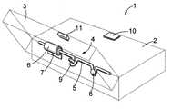
- FIG. 1is a perspective view of an embodiment of the device according to the invention.
- the device 1comprises a base part 2 and a cover part 3 which are arranged to turn with respect to each other by a hinge structure, which is not shown in the figure to simplify the illustration.
- the base part 2usually comprises the main keyboard of the device and the cover part 3 the main screen, but the components can also be arranged otherwise.
- the device 1is provided with a turning mechanism 4 which opens parts 2 and 3 from the folded position into the use position, in which the device 1 is shown in FIG. 1 .
- the device 1comprises locking members 10 , 11 with which the device 1 is locked in the folded position; when the locking is released, the turning mechanism 4 turns the parts into the use position.
- the locking members 10 , 11as well as the limiting members which define the opening angle of the use position can be implemented in manners known per se by a person skilled in the art, for which reason they will not be described in greater detail here.
- the turning mechanism 4comprises a power element 5 and a damping element 6 arranged substantially parallel therewith.
- the power element 5generates the force needed for opening the device from the folded position into the use position.
- the power element 5is a torsion spring which is attached to the base part 2 with a first attachment member 8 and to the cover part 3 with a second attachment member 9 .
- the torsion springis a spring member known per se and its spring force is generated by rotating the spring around its longitudinal axis.
- the torsion springis made of steel, for example, or of another known material used in springs.
- the attachment members 8 , 9are screws, but the attachment can also be implemented otherwise, e.g.
- the power element 5may be some other element than the torsion spring, which will be discussed more closely in connection with FIG. 6 .
- One end of the power element 5is provided with a damping element 6 , which is arranged parallel with the power element and attached to the base part 2 with a clamp 7 .
- the damping element 6can also be attached e.g. with a screw or with another fastening element known per se, or by gluing, welding, pressing or in another similar manner. It should be noted here that the dimensions between the characteristics and the details illustrated in the figures are only exemplary.
- the device 1may comprise more than one damping element 6 : both ends of the power element 5 , for example, may be provided with a damping element 6 .
- the length of the damping element 6may also correspond to the width of the whole device 1 .
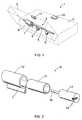
- FIG. 2is a perspective exploded view of an embodiment of the damping element in the turning mechanism according to the invention.
- the damping element 6comprises a cylindrical casing 12 inside of which a cylindrical spindle 14 is arranged substantially coaxially.
- the power element 5is attached to the spindle 14 with a clamp 15 .
- the fastening between the power element 5 and the spindle 14is preferably openable, which facilitates the disassembly and service of the turning mechanism.
- the casing 12 and the spindle 14are fitted loosely and the clearance fit between them is provided with an elastic medium 13 with certain friction properties.
- the friction properties of the adhesive material used on double-sided acrylic adhesive tapes 3MTM 9485 and 926remain substantially the same when the material is used as the elastic medium 13 and when the opening is repeated in the range of 10 5 times.
- the adhesive material on both surfaces of the above-mentioned tapesis sticky and detachably adhesive acrylic adhesive which sticks to the inner surface of the casing 12 and to the outer surface of the spindle 14 .
- the elastic medium 13does not, however, lock the casing 12 and the spindle 14 together but allows their rotation with respect to each other by the power element 5 around the longitudinal axis of the damping element 6 .
- the elastic medium 13causes friction to the rotary motion, which slows down the turn of the device parts into the use position.
- One end of the spindle 14is a shaped pin 16 which is arranged inside the hinge bushings at one end of the device to function as a hinge pin. This solution simplifies the structure of the device because no separate hinge pin is needed.
- the spindle 14can also be implemented without a pin 16 .
- FIG. 3is a partly cross-sectional view of the damping element shown in FIG. 2 .
- the elastic medium 13is placed in the space between the casing 12 and the spindle 14 .
- the friction properties of the damping elementcan be influenced significantly e.g. by the selection of the material used in the elastic medium 13 and by the dimensions of the casing 12 and the spindle 14 .
- the function of the elastic medium 13may be based e.g. on its internal friction, i.e. viscosity, elasticity, viscoelasticity, external friction against another material or on a combination thereof.
- the material of the elastic medium 13can be used as the material of the elastic medium 13 .
- the elastic medium 13can also be fixed substantially immovably either to the inner surface of the casing 12 or to the outer circumference of the spindle 14 , in which case the elastic medium 13 causes friction with the surface moving with respect to it as the device is opened, thus slowing down the opening of the device.
- the power element 5can be integrated into the damping element 6 .
- the power element 5can be integrated into the damping element 6 by selecting a suitably cross-linked silicone elastomer sheet as the elastic medium 13 and attaching its one end to the spindle 14 and the other end to the casing 12 .
- tensile stressis generated in the elastomer sheet and the release thereof is prevented e.g. by locking the device 1 parts attached to the casing 12 and the spindle 14 together.
- the tension in the elastomer sheetturns the casing 12 with respect to the spindle 14 .
- the desired damping of the turning motioncan be achieved e.g. by adjusting the thickness of the elastomer sheet with respect to the clearance fit between the casing 12 and the spindle 14 , by placing sticky material that increases friction in the clearance fit or in another suitable manner so that sufficient friction is generated between the surfaces of the sheet and the above-mentioned parts.
- the power element 5 integrated into the damping element 6is particularly well suited for turning a light cover or the like, for example.
- the casing 12is preferably made of plastic and the spindle 14 of metal or plastic, but naturally other materials can also be used.
- FIG. 4is a cross-sectional view of another embodiment of the damping element in the turning mechanism according to the invention.
- the inner surface of the casing 12is round as in the embodiments described above.
- the spindle 14has a substantially quadrangular cross-section with rounded corners.
- the elastic medium 13 ′is attached to the inner surface of the casing 12 e.g. by gluing, welding or in another manner known per se.
- the elastic medium 13 ′consists of a suitably elastic material, such as cellular rubber or plastic, elastomer or the like.
- the spindle 14 ′is dimensioned to allow its corners to compress the elastic medium 13 ′.
- the elastic medium 13 ′resists rotation of the spindle 14 ′ and the parts of the device open slowly into the use position.
- the spindle 14 ′does not need to be quadrangular in cross-section, but may also resemble some other polygon. It should be noted that in this application the term ‘polygon’ refers to any shape of a cross-section on the circumference of which there is at least one protrusion that presses the elastic medium 13 ′ differently than some other section of the circumference. The cross-section does not need to be similar along the whole length of the spindle 14 ′.
- the elastic medium 13 ′may be integrated into the casing 12 e.g. as follows: the outer part functioning as the casing is made of non-foamed plastic and the inner part functioning as the elastic medium of elastic foamed plastic.
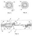
- FIG. 5is a partly sectional side view of a third turning mechanism according to the invention in which the device is in the folded position.
- the turning mechanism 4comprises a power element 5 , which is a torsion spring, and a damping element 6 which lock together substantially immovably at a clamp 15 .
- the damping element 6is preferably fixed detachably to the base part with a clamp 7 .
- the torsion springis provided with two bends of which the first bend 17 is fixed substantially immovably to a first counterpart 19 mounted in the base part 2 and the second bend 18 in the same way to a second counterpart 20 mounted in the cover part 3 .
- the counterparts 19 and 20are pocket-like structures inside of which the bends 17 and 18 are simply pushed during the assembly.
- the turning mechanismcan also be attached to the device parts 2 and 3 inversely, i.e. the damping element 6 and the first bend 17 can be attached to the cover part 3 and the second bend 18 to the base part 2 .
- the torsion springIn the folded position shown in FIG. 5 the torsion spring is tense between the bends 17 and 18 .
- the bends 17 and 18tend to rotate in the opposite directions with respect to each other around the longitudinal axis of the torsion spring upwards from the level shown in the figure, but the locking between the parts 2 and 3 prevents this.
- the torsion springcan rotate towards its relaxed position; at the same time the spring force rotates the parts 2 and 3 attached to the bends 17 and 18 by the counterparts 19 and 20 with respect to each other.
- the spindle 14 attached to the torsion springrotates inside the casing 12 along with the second bend 18 and the cover part 3 .
- the friction caused by the elastic medium 13 between the casing 12 and the spindle 14slows down the turning motion of the cover part 3 attached to the second bend 18 .
- One end of the spindle 14is provided with a pin 16 ′, which extends to one end of the device inside the hinge bushings 21 , 22 and functions as the hinge pin of these hinge bushings.
- a pin 16 ′extends to one end of the device inside the hinge bushings 21 , 22 and functions as the hinge pin of these hinge bushings.
- the end of the torsion springfunctions as a hinge pin. It is also possible that the hinge elements of the device and their hinge pins and other similar parts are totally separate from the turning mechanism 4 .
- FIG. 6is a partly sectional side view of a fourth turning mechanism according to the invention in which the device is in the folded position.
- the power element 5is a coil spring one end of which is attached to the spindle 14 of the damping element 6 and the opposite end to the hinge bushing 21 of the base part 2 in the device.
- the turning mechanismis arranged to close the first part 2 and the second part 3 of the device to fold them against each other as shown in the figure, i.e. contrary to the embodiments shown in the preceding figures.
- Any known spring memberwhich is arranged to turn the parts 2 and 3 of the device 1 with respect to each other can be used as the power element 5 .
- the casing 12 of the damping element 6is attached to the base part 2 and the spindle to the cover part 3 with a locking member 24 .
- the locking member 24is e.g. a screw, wedge, rivet or another attachment member known per se.
- the spindle 14can also be attached to the cover part 3 by gluing, welding, pressing, shaping the parts or in another similar manner; the spindle 14 can also be attached from some other part.
- locking members 25 , 26which are known per se by a person skilled in the art and will thus not be described more closely here.
- the springIn the position shown in the figure the spring is substantially relaxed. When the parts 2 and 3 are turned into the use position, the spring tenses up. When the parts are released from the locking of the locking members 25 , 26 , the spring force rotates the spindle and the cover part 3 attached thereto with respect to the base part 2 . The elastic medium 13 slows down the turning motion as was described in connection with the preceding figures.
- the power element 5may be an entity separate from the damping element 6 which generates the opening force needed, and the spindle 14 , 14 ′ and the casing may be attached to different parts 2 and 3 of the device.
- the devicemay comprise more than two parts arranged to turn with respect to each other as well as screens and keyboards mounted in the exterior sides of the device. The angle between the device parts 2 and 3 in the use position can be adjusted as desired by adjusting the characteristics of the turning mechanism.
Landscapes
- Engineering & Computer Science (AREA)
- Computer Hardware Design (AREA)
- Theoretical Computer Science (AREA)
- Physics & Mathematics (AREA)
- Human Computer Interaction (AREA)
- General Engineering & Computer Science (AREA)
- General Physics & Mathematics (AREA)
- Mathematical Physics (AREA)
- Pivots And Pivotal Connections (AREA)
- Casings For Electric Apparatus (AREA)
Abstract
Description
Claims (33)
Applications Claiming Priority (2)
| Application Number | Priority Date | Filing Date | Title |
|---|---|---|---|
| FI20001295 | 2000-05-30 | ||
| FI20001295AFI20001295A7 (en) | 2000-05-30 | 2000-05-30 | A pivoting mechanism for achieving a pivoting movement and a hinged electronic device |
Publications (2)
| Publication Number | Publication Date |
|---|---|
| US20020002884A1 US20020002884A1 (en) | 2002-01-10 |
| US6510588B2true US6510588B2 (en) | 2003-01-28 |
Family
ID=8558467
Family Applications (1)
| Application Number | Title | Priority Date | Filing Date |
|---|---|---|---|
| US09/865,118Expired - LifetimeUS6510588B2 (en) | 2000-05-30 | 2001-05-24 | Turning mechanism for providing turning motion, and hinged electronic device |
Country Status (3)
| Country | Link |
|---|---|
| US (1) | US6510588B2 (en) |
| EP (1) | EP1160467A1 (en) |
| FI (1) | FI20001295A7 (en) |
Cited By (24)
| Publication number | Priority date | Publication date | Assignee | Title |
|---|---|---|---|---|
| US20030173369A1 (en)* | 2000-12-07 | 2003-09-18 | Rexam Cosmetic Packaging, Inc. | Container system |
| US20030201265A1 (en)* | 2002-04-25 | 2003-10-30 | Tsong-Yow Lin | Garbage bin with cover |
| US20030213101A1 (en)* | 2002-05-15 | 2003-11-20 | First International Computer, Inc. | Hinge assembly for notebook computers |
| WO2003107574A3 (en)* | 2002-06-13 | 2004-07-29 | Motorola Inc | Electronics devices with spring biased hinges and methods therefor |
| US20040195113A1 (en)* | 2002-07-10 | 2004-10-07 | Takashi Yoshizawa | Eyeglasses case |
| US20040206758A1 (en)* | 2003-04-18 | 2004-10-21 | Tsong-Yow Lin | Garbage storage device |
| US20040252490A1 (en)* | 2003-06-12 | 2004-12-16 | Tsong-Yow Lin | Trash storage apparatus |
| US20040261225A1 (en)* | 2003-06-26 | 2004-12-30 | Itw Industrial Components S.R.L | Decelerating device for insertion between two relatively rotating members, in particular a drum and an oscillating door for loading the drum in a top-loaded washing machine |
| US20050034274A1 (en)* | 2003-08-12 | 2005-02-17 | Wu Ching Sung | Hinge |
| US6883676B2 (en) | 2002-07-26 | 2005-04-26 | Tsong-Yow Lin | Garbage storage device |
| US20060000059A1 (en)* | 2004-07-01 | 2006-01-05 | Radio Systems Corporation | Pet door hinge |
| US7055215B1 (en)* | 2003-12-19 | 2006-06-06 | Apple Computer, Inc. | Hinge assembly |
| US20060249510A1 (en)* | 2005-03-30 | 2006-11-09 | Tsong-Yow Lin | Waste container with buffering device |
| US20060272129A1 (en)* | 2005-06-04 | 2006-12-07 | Torqmaster, Inc. | Friction hinge with viscous damping |
| USRE39726E1 (en) | 2001-01-19 | 2007-07-17 | Tsong-Yow Lin | Waste bin structure |
| US20070163373A1 (en)* | 2006-01-06 | 2007-07-19 | Jarllytec Co., Ltd. | Labor-saving pivotal shaft structure |
| US20080151476A1 (en)* | 2006-12-21 | 2008-06-26 | Jr-Jiun Chern | Hinge for laptop computer |
| US20100208417A1 (en)* | 2007-06-15 | 2010-08-19 | Polymer Vision Limited | Electronic device with a variable angulation of a flexible display |
| US20110293356A1 (en)* | 2010-06-01 | 2011-12-01 | Reell Precision Manufacturing Corporation | Positioning and damper device using shear force from cyclic differential compressive strain of a cross-linked thermoplastic |
| US20120008277A1 (en)* | 2010-07-08 | 2012-01-12 | Dell Products L.P. | IHS Securing System |
| US8289685B2 (en)* | 2010-04-23 | 2012-10-16 | Hong Fu Jin Precision Industry (Shenzhen) Co., Ltd. | Portable electronic device |
| US8959717B2 (en) | 2012-03-12 | 2015-02-24 | Reell Precision Manufacturing Corporation | Circumferential strain rotary detent |
| US9388615B2 (en)* | 2014-05-20 | 2016-07-12 | Ami Industries, Inc. | Deformable stow box door hinge |
| US9963276B1 (en)* | 2014-04-25 | 2018-05-08 | The Eastern Company | Latch and release mechanisms for waste containers |
Families Citing this family (7)
| Publication number | Priority date | Publication date | Assignee | Title |
|---|---|---|---|---|
| WO2007093191A1 (en)* | 2006-02-16 | 2007-08-23 | Amboina Ag | Damping device for movable parts, in particular for hinges or extendable or pivotable furniture parts |
| US20080034540A1 (en)* | 2006-08-11 | 2008-02-14 | Hal Avery | Hinge System |
| FR2924463A1 (en)* | 2007-12-03 | 2009-06-05 | Qualipac Soc Par Actions Simpl | Box e.g. case, for packaging cosmetic product, has axle and brake positioned in manner coaxial with rotation axis of lid, where movement of lid with respect to bottom is dampened by friction between cylindrical part of axle and brake |
| US9348372B2 (en)* | 2014-06-13 | 2016-05-24 | Apple Inc. | Friction hinge with embedded counterbalance |
| US9725940B2 (en) | 2014-07-24 | 2017-08-08 | Michael Lambright | Door hinge closing mechanism |
| FR3053748B1 (en)* | 2016-07-06 | 2018-07-13 | A Raymond Et Cie | REINFORCED TORSION BAR HING ASSEMBLY |
| US11035164B2 (en)* | 2019-07-10 | 2021-06-15 | Deere & Company | Adjustable torsional door rod |
Citations (20)
| Publication number | Priority date | Publication date | Assignee | Title |
|---|---|---|---|---|
| DE2329073A1 (en)* | 1973-06-07 | 1975-01-02 | Porsche Ag | LIDS FOR VEHICLES, IN PARTICULAR MOTOR VEHICLES |
| US4358870A (en) | 1980-08-14 | 1982-11-16 | Hong Chang H | Hydraulic hinge with door closing mechanism |
| US4574423A (en) | 1983-02-09 | 1986-03-11 | Fuji Seiki Kabushiki Kaisha | Rotary damper having a clutch spring and viscous fluid |
| US4614004A (en) | 1983-11-07 | 1986-09-30 | Nifco Inc. | Oil filled rotary damper having a symmetrically shaped flexible membrane |
| US4721310A (en) | 1984-07-02 | 1988-01-26 | Irvin Industries, Inc. | Vehicle accessory assembly for mounting on a visor or other interior panel |
| EP0396354A2 (en) | 1989-05-02 | 1990-11-07 | Sugatsune Industrial Co., Ltd. | A damper for a flapdoor using viscous fluid |
| US5142738A (en) | 1990-07-24 | 1992-09-01 | Nhk Spring Co., Ltd. | Hinge device |
| US5165145A (en)* | 1990-09-27 | 1992-11-24 | Smith Corona Corporation | Hinge for use with portable electronic apparatus |
| US5382108A (en)* | 1990-11-21 | 1995-01-17 | Nhk Spring Co., Ltd. | Slow-acting rotary shaft device |
| US5566048A (en) | 1994-06-02 | 1996-10-15 | Hewlett-Packard Company | Hinge assembly for a device having a display |
| US5566424A (en)* | 1995-05-08 | 1996-10-22 | International Business Machines Corporation | Tilt adjustment mechanism |
| US5572768A (en)* | 1994-04-13 | 1996-11-12 | Enidine Incorporated | Door closer |
| US5636275A (en) | 1995-03-31 | 1997-06-03 | Fujitsu Limited | Hinge mechanism and foldable portable telephone having the hinge mechanism |
| US5682645A (en) | 1993-10-18 | 1997-11-04 | Koichi Watabe | Control assembly for a hinge connection |
| US5771540A (en)* | 1997-01-22 | 1998-06-30 | Torqmaster, Inc. | Equilibrated hinge with variable frictional torque |
| US5799371A (en)* | 1997-05-20 | 1998-09-01 | Tamarack Technologies Inc. | Pivoting joint |
| US6070494A (en)* | 1998-09-18 | 2000-06-06 | Horng; Chin Fu | Straight axle type rotating axle structure |
| US6085388A (en)* | 1997-04-21 | 2000-07-11 | Katoh Electrical Machinery Co., Ltd. | Operating device for openable and closable structure |
| US6125559A (en)* | 1996-12-10 | 2000-10-03 | The Gledhill Road Machinery Co. | Plow trip board biased by elastic torsion joint |
| US6317927B1 (en)* | 1999-10-26 | 2001-11-20 | Hon Hai Precision Ind. Co., Ltd. | Hinge device |
Family Cites Families (2)
| Publication number | Priority date | Publication date | Assignee | Title |
|---|---|---|---|---|
| JP3753801B2 (en)* | 1996-08-01 | 2006-03-08 | 富士通株式会社 | Hinge module and folding mobile phone having the same |
| JPH11141536A (en)* | 1997-11-13 | 1999-05-25 | Chuo Spring Co Ltd | Rotary hinge with torque damper |
- 2000
- 2000-05-30FIFI20001295Apatent/FI20001295A7/ennot_activeApplication Discontinuation
- 2001
- 2001-04-09EPEP01000108Apatent/EP1160467A1/ennot_activeWithdrawn
- 2001-05-24USUS09/865,118patent/US6510588B2/ennot_activeExpired - Lifetime
Patent Citations (21)
| Publication number | Priority date | Publication date | Assignee | Title |
|---|---|---|---|---|
| DE2329073A1 (en)* | 1973-06-07 | 1975-01-02 | Porsche Ag | LIDS FOR VEHICLES, IN PARTICULAR MOTOR VEHICLES |
| US4358870A (en) | 1980-08-14 | 1982-11-16 | Hong Chang H | Hydraulic hinge with door closing mechanism |
| US4574423A (en) | 1983-02-09 | 1986-03-11 | Fuji Seiki Kabushiki Kaisha | Rotary damper having a clutch spring and viscous fluid |
| US4614004A (en) | 1983-11-07 | 1986-09-30 | Nifco Inc. | Oil filled rotary damper having a symmetrically shaped flexible membrane |
| US4721310A (en) | 1984-07-02 | 1988-01-26 | Irvin Industries, Inc. | Vehicle accessory assembly for mounting on a visor or other interior panel |
| EP0396354A2 (en) | 1989-05-02 | 1990-11-07 | Sugatsune Industrial Co., Ltd. | A damper for a flapdoor using viscous fluid |
| US5165507A (en)* | 1989-05-02 | 1992-11-24 | Sugatsune Industrial Co., Ltd. | Damper for a flapdoor using viscous fluid |
| US5142738A (en) | 1990-07-24 | 1992-09-01 | Nhk Spring Co., Ltd. | Hinge device |
| US5165145A (en)* | 1990-09-27 | 1992-11-24 | Smith Corona Corporation | Hinge for use with portable electronic apparatus |
| US5382108A (en)* | 1990-11-21 | 1995-01-17 | Nhk Spring Co., Ltd. | Slow-acting rotary shaft device |
| US5682645A (en) | 1993-10-18 | 1997-11-04 | Koichi Watabe | Control assembly for a hinge connection |
| US5572768A (en)* | 1994-04-13 | 1996-11-12 | Enidine Incorporated | Door closer |
| US5566048A (en) | 1994-06-02 | 1996-10-15 | Hewlett-Packard Company | Hinge assembly for a device having a display |
| US5636275A (en) | 1995-03-31 | 1997-06-03 | Fujitsu Limited | Hinge mechanism and foldable portable telephone having the hinge mechanism |
| US5566424A (en)* | 1995-05-08 | 1996-10-22 | International Business Machines Corporation | Tilt adjustment mechanism |
| US6125559A (en)* | 1996-12-10 | 2000-10-03 | The Gledhill Road Machinery Co. | Plow trip board biased by elastic torsion joint |
| US5771540A (en)* | 1997-01-22 | 1998-06-30 | Torqmaster, Inc. | Equilibrated hinge with variable frictional torque |
| US6085388A (en)* | 1997-04-21 | 2000-07-11 | Katoh Electrical Machinery Co., Ltd. | Operating device for openable and closable structure |
| US5799371A (en)* | 1997-05-20 | 1998-09-01 | Tamarack Technologies Inc. | Pivoting joint |
| US6070494A (en)* | 1998-09-18 | 2000-06-06 | Horng; Chin Fu | Straight axle type rotating axle structure |
| US6317927B1 (en)* | 1999-10-26 | 2001-11-20 | Hon Hai Precision Ind. Co., Ltd. | Hinge device |
Non-Patent Citations (2)
| Title |
|---|
| Japanese Patent document No. JP11141536, English translation of the Abstract attached. |
| Japanese Patent document No. JP2000145269, English translation of the Abstract attached. |
Cited By (40)
| Publication number | Priority date | Publication date | Assignee | Title |
|---|---|---|---|---|
| US20030173369A1 (en)* | 2000-12-07 | 2003-09-18 | Rexam Cosmetic Packaging, Inc. | Container system |
| USRE39726E1 (en) | 2001-01-19 | 2007-07-17 | Tsong-Yow Lin | Waste bin structure |
| US6857538B2 (en)* | 2002-04-25 | 2005-02-22 | Tsong-Yow Lin | Garbage bin with cover |
| US20030201265A1 (en)* | 2002-04-25 | 2003-10-30 | Tsong-Yow Lin | Garbage bin with cover |
| US20030213101A1 (en)* | 2002-05-15 | 2003-11-20 | First International Computer, Inc. | Hinge assembly for notebook computers |
| US6895638B2 (en)* | 2002-05-15 | 2005-05-24 | First International Computer Inc. | Hinge assembly for notebook computers |
| WO2003107574A3 (en)* | 2002-06-13 | 2004-07-29 | Motorola Inc | Electronics devices with spring biased hinges and methods therefor |
| US20040166890A1 (en)* | 2002-06-13 | 2004-08-26 | Ryszard Gordecki | Electronics devices with spring biased hinges and methods therefor |
| US7111362B2 (en)* | 2002-06-13 | 2006-09-26 | Motorola, Inc. | Electronics devices with spring biased hinges and methods therefor |
| GB2405050B (en)* | 2002-06-13 | 2005-10-26 | Motorola Inc | Electronics devices with spring biased hinges and methods therefor |
| GB2405050A (en)* | 2002-06-13 | 2005-02-16 | Motorola Inc | Electronics devices with spring biased hinges and methods therefor |
| US20040195113A1 (en)* | 2002-07-10 | 2004-10-07 | Takashi Yoshizawa | Eyeglasses case |
| US6883676B2 (en) | 2002-07-26 | 2005-04-26 | Tsong-Yow Lin | Garbage storage device |
| US6920994B2 (en) | 2003-04-18 | 2005-07-26 | Tsong-Yow Lin | Garbage storage device |
| US20040206758A1 (en)* | 2003-04-18 | 2004-10-21 | Tsong-Yow Lin | Garbage storage device |
| US7033039B2 (en) | 2003-06-12 | 2006-04-25 | Tsong-Yow Lin | Trash storage apparatus |
| US20040252490A1 (en)* | 2003-06-12 | 2004-12-16 | Tsong-Yow Lin | Trash storage apparatus |
| US20040261225A1 (en)* | 2003-06-26 | 2004-12-30 | Itw Industrial Components S.R.L | Decelerating device for insertion between two relatively rotating members, in particular a drum and an oscillating door for loading the drum in a top-loaded washing machine |
| US7257862B2 (en)* | 2003-06-26 | 2007-08-21 | Itw Industrial Components S.R.L. | Decelerating device for insertion between two relatively rotating members, in particular a drum and an oscillating door for loading the drum in a top-loaded washing machine |
| US20050034274A1 (en)* | 2003-08-12 | 2005-02-17 | Wu Ching Sung | Hinge |
| US7055215B1 (en)* | 2003-12-19 | 2006-06-06 | Apple Computer, Inc. | Hinge assembly |
| US7120967B2 (en)* | 2004-07-01 | 2006-10-17 | Radio Systems Corporation | Pet door hinge |
| US20060000059A1 (en)* | 2004-07-01 | 2006-01-05 | Radio Systems Corporation | Pet door hinge |
| US20060249510A1 (en)* | 2005-03-30 | 2006-11-09 | Tsong-Yow Lin | Waste container with buffering device |
| US20060272129A1 (en)* | 2005-06-04 | 2006-12-07 | Torqmaster, Inc. | Friction hinge with viscous damping |
| US20070163373A1 (en)* | 2006-01-06 | 2007-07-19 | Jarllytec Co., Ltd. | Labor-saving pivotal shaft structure |
| US7743466B2 (en)* | 2006-01-06 | 2010-06-29 | Jarllytec Co., Ltd. | Labor-saving pivotal shaft structure |
| US20080151476A1 (en)* | 2006-12-21 | 2008-06-26 | Jr-Jiun Chern | Hinge for laptop computer |
| US7690081B2 (en)* | 2006-12-21 | 2010-04-06 | Jr-Jiun Chern | Hinge for laptop computer |
| US8477464B2 (en)* | 2007-06-15 | 2013-07-02 | Creator Technology B.V. | Electronic device with a variable angulation of a flexible display |
| US20100208417A1 (en)* | 2007-06-15 | 2010-08-19 | Polymer Vision Limited | Electronic device with a variable angulation of a flexible display |
| US8289685B2 (en)* | 2010-04-23 | 2012-10-16 | Hong Fu Jin Precision Industry (Shenzhen) Co., Ltd. | Portable electronic device |
| US20110293356A1 (en)* | 2010-06-01 | 2011-12-01 | Reell Precision Manufacturing Corporation | Positioning and damper device using shear force from cyclic differential compressive strain of a cross-linked thermoplastic |
| US8523476B2 (en)* | 2010-06-01 | 2013-09-03 | Reell Precision Manufacturing Corporation | Positioning and damper device using shear force from cyclic differential compressive strain of a cross-linked thermoplastic |
| US20120008277A1 (en)* | 2010-07-08 | 2012-01-12 | Dell Products L.P. | IHS Securing System |
| US8432688B2 (en)* | 2010-07-08 | 2013-04-30 | Dell Products L.P. | IHS securing system |
| US8959717B2 (en) | 2012-03-12 | 2015-02-24 | Reell Precision Manufacturing Corporation | Circumferential strain rotary detent |
| US9963276B1 (en)* | 2014-04-25 | 2018-05-08 | The Eastern Company | Latch and release mechanisms for waste containers |
| US9388615B2 (en)* | 2014-05-20 | 2016-07-12 | Ami Industries, Inc. | Deformable stow box door hinge |
| US9803406B2 (en) | 2014-05-20 | 2017-10-31 | Ami Industries, Inc. | Deformable stow box door hinge |
Also Published As
| Publication number | Publication date |
|---|---|
| FI20001295L (en) | 2001-12-01 |
| FI20001295A7 (en) | 2001-12-01 |
| EP1160467A1 (en) | 2001-12-05 |
| US20020002884A1 (en) | 2002-01-10 |
Similar Documents
| Publication | Publication Date | Title |
|---|---|---|
| US6510588B2 (en) | Turning mechanism for providing turning motion, and hinged electronic device | |
| US6754081B2 (en) | Pop-up friction hinge having multiple levels of torque | |
| CA2277142A1 (en) | Equilibrated hinge with variable frictional torque | |
| DE602004014734D1 (en) | ROTATION MECHANISM WITH BIAXIAL JOINT AND PORTABLE TELEPHONE THEREOF | |
| JP4733705B2 (en) | Damper device | |
| JP4199230B2 (en) | Hinge structure of vehicle glove box | |
| JP4559816B2 (en) | Display device | |
| JPH08121009A (en) | Hinge mechanism | |
| US6606762B1 (en) | Hinge for a rotatably connected cover | |
| EP1355029A2 (en) | Damper | |
| JP3280756B2 (en) | Folding door for aircraft | |
| US7111773B1 (en) | Damped, mechanically driven lid for a handheld device | |
| CN1089146C (en) | Hinge retarding device | |
| KR102469188B1 (en) | Safety Hinge | |
| WO1995014842A1 (en) | Friction hinge with detent | |
| JP2001187934A (en) | Rotary damper | |
| JP2001037630A (en) | Cover opening and closing mechanism for rice cooker | |
| KR940015142A (en) | Car door hinges | |
| JP2001173635A (en) | Hinge device | |
| GB2226361A (en) | Telescopic spring | |
| JPH08291667A (en) | Hinge device | |
| CN113124278A (en) | Accessory sheath | |
| US20040078932A1 (en) | Torque regulator device for hinge assembly | |
| KR200173301Y1 (en) | Hinge device | |
| KR100308168B1 (en) | Hinges for Portable Computers |
Legal Events
| Date | Code | Title | Description |
|---|---|---|---|
| AS | Assignment | Owner name:NOKIA MOBILE PHONES LTD., FINLAND Free format text:ASSIGNMENT OF ASSIGNORS INTEREST;ASSIGNOR:EROMAKI, MARKO;REEL/FRAME:012052/0307 Effective date:20010612 | |
| STCF | Information on status: patent grant | Free format text:PATENTED CASE | |
| FPAY | Fee payment | Year of fee payment:4 | |
| AS | Assignment | Owner name:NOKIA CAPITAL, INC., NEW YORK Free format text:ASSIGNMENT OF ASSIGNORS INTEREST;ASSIGNOR:NOKIA CORPORATION;REEL/FRAME:023821/0468 Effective date:20100111 Owner name:MOBILEMEDIA IDEAS LLC, MARYLAND Free format text:ASSIGNMENT OF ASSIGNORS INTEREST;ASSIGNOR:NOKIA CAPITAL, INC;REEL/FRAME:023828/0457 Effective date:20100111 | |
| FPAY | Fee payment | Year of fee payment:8 | |
| FEPP | Fee payment procedure | Free format text:PAYOR NUMBER ASSIGNED (ORIGINAL EVENT CODE: ASPN); ENTITY STATUS OF PATENT OWNER: LARGE ENTITY | |
| FPAY | Fee payment | Year of fee payment:12 | |
| AS | Assignment | Owner name:IRONWORKS PATENTS LLC, ILLINOIS Free format text:ASSIGNMENT OF ASSIGNORS INTEREST;ASSIGNOR:MOBILEMEDIA IDEAS LLC;REEL/FRAME:042107/0440 Effective date:20170327 |