US6510396B1 - Symmetry compensation for encoder pulse width variation - Google Patents
Symmetry compensation for encoder pulse width variationDownload PDFInfo
- Publication number
- US6510396B1 US6510396B1US09/661,221US66122100AUS6510396B1US 6510396 B1US6510396 B1US 6510396B1US 66122100 AUS66122100 AUS 66122100AUS 6510396 B1US6510396 B1US 6510396B1
- Authority
- US
- United States
- Prior art keywords
- motor
- signals
- ary
- set forth
- calculating
- Prior art date
- Legal status (The legal status is an assumption and is not a legal conclusion. Google has not performed a legal analysis and makes no representation as to the accuracy of the status listed.)
- Expired - Fee Related, expires
Links
- 238000000034methodMethods0.000claimsabstractdescription35
- 238000005259measurementMethods0.000claimsabstractdescription14
- 230000001960triggered effectEffects0.000claimsdescription3
- 239000011521glassSubstances0.000claimsdescription2
- 230000005355Hall effectEffects0.000claims1
- 238000004590computer programMethods0.000description5
- 238000012937correctionMethods0.000description4
- 238000004364calculation methodMethods0.000description3
- 238000010586diagramMethods0.000description3
- 238000013459approachMethods0.000description2
- 230000005540biological transmissionEffects0.000description1
- 238000009429electrical wiringMethods0.000description1
- 230000005670electromagnetic radiationEffects0.000description1
- 239000000835fiberSubstances0.000description1
- 238000012986modificationMethods0.000description1
- 230000004048modificationEffects0.000description1
- 238000012544monitoring processMethods0.000description1
Images


Classifications
- G—PHYSICS
- G01—MEASURING; TESTING
- G01D—MEASURING NOT SPECIALLY ADAPTED FOR A SPECIFIC VARIABLE; ARRANGEMENTS FOR MEASURING TWO OR MORE VARIABLES NOT COVERED IN A SINGLE OTHER SUBCLASS; TARIFF METERING APPARATUS; MEASURING OR TESTING NOT OTHERWISE PROVIDED FOR
- G01D5/00—Mechanical means for transferring the output of a sensing member; Means for converting the output of a sensing member to another variable where the form or nature of the sensing member does not constrain the means for converting; Transducers not specially adapted for a specific variable
- G01D5/12—Mechanical means for transferring the output of a sensing member; Means for converting the output of a sensing member to another variable where the form or nature of the sensing member does not constrain the means for converting; Transducers not specially adapted for a specific variable using electric or magnetic means
- G01D5/244—Mechanical means for transferring the output of a sensing member; Means for converting the output of a sensing member to another variable where the form or nature of the sensing member does not constrain the means for converting; Transducers not specially adapted for a specific variable using electric or magnetic means influencing characteristics of pulses or pulse trains; generating pulses or pulse trains
- G01D5/245—Mechanical means for transferring the output of a sensing member; Means for converting the output of a sensing member to another variable where the form or nature of the sensing member does not constrain the means for converting; Transducers not specially adapted for a specific variable using electric or magnetic means influencing characteristics of pulses or pulse trains; generating pulses or pulse trains using a variable number of pulses in a train
- G01D5/2451—Incremental encoders
- B—PERFORMING OPERATIONS; TRANSPORTING
- B62—LAND VEHICLES FOR TRAVELLING OTHERWISE THAN ON RAILS
- B62D—MOTOR VEHICLES; TRAILERS
- B62D5/00—Power-assisted or power-driven steering
- B62D5/04—Power-assisted or power-driven steering electrical, e.g. using an electric servo-motor connected to, or forming part of, the steering gear
- B62D5/0457—Power-assisted or power-driven steering electrical, e.g. using an electric servo-motor connected to, or forming part of, the steering gear characterised by control features of the drive means as such
- B62D5/046—Controlling the motor
- G—PHYSICS
- G01—MEASURING; TESTING
- G01D—MEASURING NOT SPECIALLY ADAPTED FOR A SPECIFIC VARIABLE; ARRANGEMENTS FOR MEASURING TWO OR MORE VARIABLES NOT COVERED IN A SINGLE OTHER SUBCLASS; TARIFF METERING APPARATUS; MEASURING OR TESTING NOT OTHERWISE PROVIDED FOR
- G01D18/00—Testing or calibrating apparatus or arrangements provided for in groups G01D1/00 - G01D15/00
- G01D18/001—Calibrating encoders
- H—ELECTRICITY
- H02—GENERATION; CONVERSION OR DISTRIBUTION OF ELECTRIC POWER
- H02P—CONTROL OR REGULATION OF ELECTRIC MOTORS, ELECTRIC GENERATORS OR DYNAMO-ELECTRIC CONVERTERS; CONTROLLING TRANSFORMERS, REACTORS OR CHOKE COILS
- H02P6/00—Arrangements for controlling synchronous motors or other dynamo-electric motors using electronic commutation dependent on the rotor position; Electronic commutators therefor
- H02P6/14—Electronic commutators
- H02P6/16—Circuit arrangements for detecting position
Definitions
- This inventionrelates to compensating for errors in the measurement of the kinematic properties of an electric power steering motor for an automobile.
- An electric power steering apparatus for a motor vehicle or automobiletypically uses an electric motor to assist an operator in applying the necessary torque required to steer the vehicle.
- a sensor in the electric power steering apparatusdetects the angular position and/or velocity of the motor.
- a signalis then sent from the sensor to an electric controller.
- the electric controllercontrols the magnitude and direction of the steering assist provided by the electric motor.
- the electric motordrives a reducing gear, typically a worm gear engaging a worm wheel, that lessens the torque required to turn the steering wheel.
- Electric steering systemsoften utilize a motor with a digital encoder for a position sensor.
- Electric power steering systems for motor vehiclesmay require motor velocity as part of the control law.
- a time derivative of motor position or direct measurement of motor velocitymust be performed.
- a relatively low resolution position sensoris desireable.
- a technology used for this motor sensing functionincludes a magnetic target with corresponding magnetic sensors (i.e., Hall Sensors).
- One problem of utilizing this approachis the potential variability of the output signals.
- a second problem with this approachis that at low motor velocities, the low resolution of the sensor does not provide sufficient angular input resolution for a time base derivative where the position change is variable and the time base is constant. Therefore, the time base derivative must be based on a constant position change and a variable time base. This causes the derivative to be very sensitive to errors in the angular position signal.
- a method of compensating for errors in the measurement of the kinematic properties of an electric power steering motor for an automobilecomprises generating a set of M-ary signals; measuring the pulse width of the set of M-ary signals; and measuring the time between the edges of the set of M-ary signals.
- the motor position signalcan be used to estimate the angular velocity of the motor, by determining the change in angular position of the motor divided by the change in time.
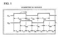
- FIG. 1is a diagram of a set of idealized binary symmetric signals in quadrature
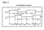
- FIG. 2is a diagram of a set of real binary non-symmetric signals not in quadrature.
- FIG. 3is a block diagram of a control system for implementing a method of compensating for errors in the measurement of the kinematic properties of a motor.
- the control system 100comprises a pulse encoded position sensor target 104 attached to a motor shaft (not shown) as the rotating half of a motor position sensor system 104 , 108 .
- Typical position sensor targetsutilize slotted disks, etched glass or magnetic disks.
- the position sensor target 104is operative to accept as input thereto the motor angular position signal 102 .
- the position sensor target 104provides as output a signal 106 .
- a position sensor receiver 108for example Hall sensors, are attached to the non-rotating part of the motor and accept the signal 106 as input thereto.
- the position sensor receiver 108provides as output a set of M-ary phase shifted signals 112 as seen at 112 a , 112 b , 112 c , 112 d in FIGS. 1 and 2.
- the output 112 from the position sensor receiver 108is typically a pulse train and a direction signal which represents the speed and direction of the motor or is comprised of two digital signals in quadrature (i.e., 90 degrees phase offset).
- the quadrature signal 112is in the nature of a pulse train indicative of the kinematic properties of the motor such as relative angular position, ⁇ r , of the motor shaft.
- the output signal 112is provided as input to an edge triggered timer 114 for measuring the time between the edges of the incoming pulses.
- Signal 112is also provided to a symmetry compensator 122 .
- the timer 114provides as output a signal 116 indicative of the time between the pulses of the quadrature signal 112 .
- the uncompensated or velocity, ⁇ u 120contains errors associated with errors in the measurement of the angular position, ⁇ , of the motor shaft (e.g. errors due to the mechanical positioning of the sensors at 104 ), including errors in signal symmetry and phase relationship.
- a symmetry compensation function 122accepts as input thereto digital signals 112 , 120 to determine the appropriate symmetry correction term, K s , to be applied to the uncompensated velocity, ⁇ u .
- D H⁇ H ⁇ u ( 2 ⁇ a )
- D L⁇ L ⁇ u ( 2 ⁇ b )
- v⁇ ⁇ ⁇ ⁇ ⁇ ⁇ t ( 3 ⁇ a )
- v u⁇ u t measured ( 3 ⁇ b )
- Nis the number of measurable pulses per mechanical (or electrical) cycle
- D H and D Lare the duty cycles of the sensor state (High or Low)
- I measuredis the time measured between pulses
- ⁇ cis the corrected angular velocity.
- D 10⁇ 10 ⁇ u ( 6 ⁇ a )
- D 11⁇ 11 ⁇ u ( 6 ⁇ b )
- D 01⁇ 01 ⁇ u ( 6 ⁇ c )
- D 00⁇ 00 ⁇ u ( 6 ⁇ d )
- v⁇ ⁇ ⁇ ⁇ ⁇ ⁇ ⁇ t ( 7 ⁇ a )
- v u⁇ u t measured ( 7 ⁇ b )
- a magnetic encoderis utilized for the motor position sensor target 104 .
- the motor position sensor target 104may be comprised of a magnetic disk (or cylinder) attached to the motor shaft.
- the position sensor receivers 108are comprised of two Hall sensors that are spaced to yield a quadrature signal output 112 .
- the quadrature signals 112are used to compute the relative angular position, ⁇ r , of the motor shaft as part of the position sensing subsystem 104 , 108 .
- the quadrature signals 112are provided as input into an edge triggered capture timer 114 .
- the corresponding pulse widthscan be computed by subtracting the difference in the timer values between the two edges.
- This valuecan be used to compute the nominal velocity ⁇ u .
- the velocity valuecan be compensated in software.
- ⁇ u⁇ H + ⁇ L 2 ( 9 )
- ⁇ L2 ⁇ ⁇ u - ⁇ H ( 10 )
- D H⁇ H ⁇ u ( 11 ⁇ a )
- D HK H 128 ( 12 ⁇ a )
- D 10K 10 128 ( 15 ⁇ a )
- D 11K 11 128 ( 15 ⁇ b )
- D 01K 01 128 ( 15 ⁇ c )
- D 00K 00 128 ( 15 ⁇ d )
- the present inventioncan be embodied in the form of computer-implemented processes and apparatuses for practicing those processes.
- the present inventioncan also be embodied in the form of computer program code containing instructions embodied in tangible media, such as floppy diskettes, CD-ROMs, hard drives, or any other computer-readable storage medium, wherein, when the computer program code is loaded into and executed by a computer, the computer becomes an apparatus for practicing the invention.
- the present inventioncan also be embodied in the form of computer program code, for example, whether stored in a storage medium, loaded into and/or executed by a computer, or transmitted over some transmission medium, such as over electrical wiring or cabling, through fiber optics, or via electromagnetic radiation, wherein, when the computer program code is loaded into and executed by a computer, the computer becomes an apparatus for practicing the invention.
- computer program code segmentsconfigure the microprocessor to create specific logic circuits.
Landscapes
- Engineering & Computer Science (AREA)
- Physics & Mathematics (AREA)
- General Physics & Mathematics (AREA)
- Power Engineering (AREA)
- Chemical & Material Sciences (AREA)
- Combustion & Propulsion (AREA)
- Transportation (AREA)
- Mechanical Engineering (AREA)
- Transmission And Conversion Of Sensor Element Output (AREA)
- Power Steering Mechanism (AREA)
Abstract
Description


Claims (30)
Priority Applications (1)
| Application Number | Priority Date | Filing Date | Title |
|---|---|---|---|
| US09/661,221US6510396B1 (en) | 1999-09-16 | 2000-09-13 | Symmetry compensation for encoder pulse width variation |
Applications Claiming Priority (2)
| Application Number | Priority Date | Filing Date | Title |
|---|---|---|---|
| US15405599P | 1999-09-16 | 1999-09-16 | |
| US09/661,221US6510396B1 (en) | 1999-09-16 | 2000-09-13 | Symmetry compensation for encoder pulse width variation |
Publications (1)
| Publication Number | Publication Date |
|---|---|
| US6510396B1true US6510396B1 (en) | 2003-01-21 |
Family
ID=22549810
Family Applications (1)
| Application Number | Title | Priority Date | Filing Date |
|---|---|---|---|
| US09/661,221Expired - Fee RelatedUS6510396B1 (en) | 1999-09-16 | 2000-09-13 | Symmetry compensation for encoder pulse width variation |
Country Status (2)
| Country | Link |
|---|---|
| US (1) | US6510396B1 (en) |
| WO (1) | WO2001020290A1 (en) |
Cited By (14)
| Publication number | Priority date | Publication date | Assignee | Title |
|---|---|---|---|---|
| US20020146994A1 (en)* | 2001-04-09 | 2002-10-10 | Marrah Jeffrey Joseph | Phase compensation circuit |
| US20060087316A1 (en)* | 2004-10-22 | 2006-04-27 | Islam Mohammad S | Position sensor and assembly |
| US7245725B1 (en)* | 2001-05-17 | 2007-07-17 | Cypress Semiconductor Corp. | Dual processor framer |
| US20080023256A1 (en)* | 2006-07-28 | 2008-01-31 | Krieger Geoff P | Quadrant dependent active damping for electric power steering |
| US20080024028A1 (en)* | 2006-07-27 | 2008-01-31 | Islam Mohammad S | Permanent magnet electric motor |
| US20080023255A1 (en)* | 2006-07-28 | 2008-01-31 | Colosky Mark P | Compensation of periodic sensor errors in electric power steering systems |
| US20080147276A1 (en)* | 2006-12-15 | 2008-06-19 | Delphi Technologies, Inc. | Method, system, and apparatus for providing enhanced steering pull compensation |
| US20100063684A1 (en)* | 2008-09-08 | 2010-03-11 | Delphi Technologies, Inc. | Electric power steering system control methods |
| US20100194385A1 (en)* | 2007-07-24 | 2010-08-05 | Moving Magnet Technologies | Non-contact multi-turn absolute position magnetic sensor comprising a through-shaft |
| US7936854B2 (en) | 2002-11-15 | 2011-05-03 | Cypress Semiconductor Corporation | Method and system of cycle slip framing in a deserializer |
| CN101995533B (en)* | 2009-08-11 | 2013-01-09 | 深圳市英威腾电气股份有限公司 | Real-time wire-break detection method and system for digital incremental encoder |
| US20130261964A1 (en)* | 2011-12-22 | 2013-10-03 | David Allan Goldman | Systems, methods, and apparatus for providing indoor navigation using magnetic sensors |
| US9513127B2 (en) | 2011-12-22 | 2016-12-06 | AppLabz, LLC | Systems, methods, and apparatus for providing indoor navigation |
| US9702707B2 (en) | 2011-12-22 | 2017-07-11 | AppLabz, LLC | Systems, methods, and apparatus for providing indoor navigation using optical floor sensors |
Citations (37)
| Publication number | Priority date | Publication date | Assignee | Title |
|---|---|---|---|---|
| US3731533A (en) | 1969-10-16 | 1973-05-08 | Dresser Ind | Electrical generator having non-salient poles for metering shaft rotation of a turbine assembly |
| US4008378A (en)* | 1973-05-14 | 1977-02-15 | Ns Electronics | Multi-radix digital communications system with time-frequency and phase-shift multiplexing |
| US4437061A (en) | 1980-07-31 | 1984-03-13 | Matsushita Electric Industrial Co., Ltd. | Speed detector for sewing machines |
| US4562399A (en) | 1983-06-14 | 1985-12-31 | Kollmorgen Technologies Corporation | Brushless DC tachometer |
| US4803425A (en) | 1987-10-05 | 1989-02-07 | Xerox Corporation | Multi-phase printed circuit board tachometer |
| US4836319A (en)* | 1986-07-22 | 1989-06-06 | Nippondenso Co., Ltd. | Steering control apparatus for motor vehicles |
| US4838074A (en) | 1987-04-06 | 1989-06-13 | Mitsubishi Denki Kabushiki Kaisha | Steering torque detecting device |
| US4897603A (en) | 1988-02-29 | 1990-01-30 | Siemens Aktiengesellschaft | Arrangement for determining the speed and rotor position of an electric machine |
| US4922197A (en) | 1988-08-01 | 1990-05-01 | Eaton Corporation | High resolution proximity detector employing magnetoresistive sensor disposed within a pressure resistant enclosure |
| US4924161A (en) | 1988-04-06 | 1990-05-08 | Victor Company Of Japan, Ltd. | Position and speed detecting device |
| US4924696A (en) | 1989-07-24 | 1990-05-15 | General Motors Corporation | Noncontacting position sensor for an automotive steering system |
| US4955228A (en) | 1987-12-03 | 1990-09-11 | Kabushiki Kaisha Tokai-Rika-Denki Seisakusho | Device for detecting rotation of steering wheel for automobiles |
| US4961017A (en) | 1987-09-28 | 1990-10-02 | Akai Electric Co., Ltd. | Stator for use in a brushless motor |
| US4983915A (en) | 1987-04-18 | 1991-01-08 | Lothar Rossi | Device for determining the rotary angle position of rotary drives of electrical machines by evaluation of electrical voltages by sensors responding to rotary movements |
| US5027648A (en) | 1988-07-05 | 1991-07-02 | Siemens Aktiengesellschaft | Method and device for measuring the angle of rotation of the steering shaft of a motor vehicle |
| US5029466A (en) | 1989-07-13 | 1991-07-09 | Honda Giken Kogyo Kabushiki Kaisha | System for detecting abnormality of steering angle sensor |
| US5088319A (en) | 1989-12-29 | 1992-02-18 | Kabushiki Kaisha Tokai-Rika-Denki-Seisakusho | Steering angle sensor |
| US5218279A (en)* | 1990-01-08 | 1993-06-08 | Hitachi, Ltd. | Method and apparatus for detection of physical quantities, servomotor system utilizing the method and apparatus and power steering apparatus using the servomotor system |
| US5223760A (en) | 1988-08-24 | 1993-06-29 | Rockwell International Corporation | Wheel speed sensor for drive axle |
| US5293125A (en) | 1992-01-17 | 1994-03-08 | Lake Shore Cryotronics, Inc. | Self-aligning tachometer with interchangeable elements for different resolution outputs |
| US5309758A (en) | 1991-04-25 | 1994-05-10 | Honda Giken Kogyo Kabushiki Kaisha | Steering angle sensor for automobile |
| US5329195A (en) | 1992-11-02 | 1994-07-12 | Seiberco Incorporated | Sensor motor |
| US5406267A (en)* | 1991-07-22 | 1995-04-11 | Curtis; Stephen J. | Method and apparatus for the monitoring of the operation of linear and rotary encoders |
| US5408153A (en) | 1991-07-05 | 1995-04-18 | Canon Denshi Kabushiki Kaisha | Index position detecting apparatus for an electromagnetic rotary machine |
| US5498072A (en)* | 1994-05-24 | 1996-03-12 | Nissan Motor. Co., Ltd. | Anti-skid control system for automotive vehicles |
| US5503421A (en)* | 1991-07-09 | 1996-04-02 | Delisser; Chrys O. | Clutch and control mechanism for fifth wheel |
| JPH08211081A (en) | 1994-08-11 | 1996-08-20 | Nippon Seiko Kk | Rolling bearing unit with rotation speed detector |
| US5717268A (en) | 1996-06-17 | 1998-02-10 | Philips Electronics North America Corp. | Electric motor with tachometer signal generator |
| US5736852A (en) | 1995-06-21 | 1998-04-07 | Alliedsignal Truck Brake Systems Co. | Circuit and method for conditioning a wheel speed sensor signal |
| US5828973A (en) | 1995-03-17 | 1998-10-27 | Nippondenso Co., Ltd. | Electric power steering apparatus |
| US5902342A (en) | 1997-03-27 | 1999-05-11 | Abb Daimler-Benz Transportation (North America) Inc. | Detection of vibration in an AC traction system |
| US6155106A (en) | 1997-10-29 | 2000-12-05 | Alps Electric Co., Inc. | Steering angle sensor unit |
| US6244372B1 (en) | 1998-09-18 | 2001-06-12 | Koyo Seiko Co., Ltd. | Power steering apparatus |
| US6246197B1 (en)* | 1997-09-05 | 2001-06-12 | Mitsubishi Denki Kabushiki Kaisha | Electric power steering controller |
| US6244373B1 (en) | 1998-04-27 | 2001-06-12 | Toyota Jidosha Kabushiki Kaisha | Steering control apparatus for vehicle |
| US6250417B1 (en) | 1998-05-18 | 2001-06-26 | Koyo Seiko Co., Ltd. | Power steering apparatus |
| US6286621B1 (en) | 1997-08-27 | 2001-09-11 | Honda Giken Kogyo Kabushiki Kaisha | Electric power steering apparatus |
- 2000
- 2000-09-13USUS09/661,221patent/US6510396B1/ennot_activeExpired - Fee Related
- 2000-09-13WOPCT/US2000/025018patent/WO2001020290A1/enactiveApplication Filing
Patent Citations (37)
| Publication number | Priority date | Publication date | Assignee | Title |
|---|---|---|---|---|
| US3731533A (en) | 1969-10-16 | 1973-05-08 | Dresser Ind | Electrical generator having non-salient poles for metering shaft rotation of a turbine assembly |
| US4008378A (en)* | 1973-05-14 | 1977-02-15 | Ns Electronics | Multi-radix digital communications system with time-frequency and phase-shift multiplexing |
| US4437061A (en) | 1980-07-31 | 1984-03-13 | Matsushita Electric Industrial Co., Ltd. | Speed detector for sewing machines |
| US4562399A (en) | 1983-06-14 | 1985-12-31 | Kollmorgen Technologies Corporation | Brushless DC tachometer |
| US4836319A (en)* | 1986-07-22 | 1989-06-06 | Nippondenso Co., Ltd. | Steering control apparatus for motor vehicles |
| US4838074A (en) | 1987-04-06 | 1989-06-13 | Mitsubishi Denki Kabushiki Kaisha | Steering torque detecting device |
| US4983915A (en) | 1987-04-18 | 1991-01-08 | Lothar Rossi | Device for determining the rotary angle position of rotary drives of electrical machines by evaluation of electrical voltages by sensors responding to rotary movements |
| US4961017A (en) | 1987-09-28 | 1990-10-02 | Akai Electric Co., Ltd. | Stator for use in a brushless motor |
| US4803425A (en) | 1987-10-05 | 1989-02-07 | Xerox Corporation | Multi-phase printed circuit board tachometer |
| US4955228A (en) | 1987-12-03 | 1990-09-11 | Kabushiki Kaisha Tokai-Rika-Denki Seisakusho | Device for detecting rotation of steering wheel for automobiles |
| US4897603A (en) | 1988-02-29 | 1990-01-30 | Siemens Aktiengesellschaft | Arrangement for determining the speed and rotor position of an electric machine |
| US4924161A (en) | 1988-04-06 | 1990-05-08 | Victor Company Of Japan, Ltd. | Position and speed detecting device |
| US5027648A (en) | 1988-07-05 | 1991-07-02 | Siemens Aktiengesellschaft | Method and device for measuring the angle of rotation of the steering shaft of a motor vehicle |
| US4922197A (en) | 1988-08-01 | 1990-05-01 | Eaton Corporation | High resolution proximity detector employing magnetoresistive sensor disposed within a pressure resistant enclosure |
| US5223760A (en) | 1988-08-24 | 1993-06-29 | Rockwell International Corporation | Wheel speed sensor for drive axle |
| US5029466A (en) | 1989-07-13 | 1991-07-09 | Honda Giken Kogyo Kabushiki Kaisha | System for detecting abnormality of steering angle sensor |
| US4924696A (en) | 1989-07-24 | 1990-05-15 | General Motors Corporation | Noncontacting position sensor for an automotive steering system |
| US5088319A (en) | 1989-12-29 | 1992-02-18 | Kabushiki Kaisha Tokai-Rika-Denki-Seisakusho | Steering angle sensor |
| US5218279A (en)* | 1990-01-08 | 1993-06-08 | Hitachi, Ltd. | Method and apparatus for detection of physical quantities, servomotor system utilizing the method and apparatus and power steering apparatus using the servomotor system |
| US5309758A (en) | 1991-04-25 | 1994-05-10 | Honda Giken Kogyo Kabushiki Kaisha | Steering angle sensor for automobile |
| US5408153A (en) | 1991-07-05 | 1995-04-18 | Canon Denshi Kabushiki Kaisha | Index position detecting apparatus for an electromagnetic rotary machine |
| US5503421A (en)* | 1991-07-09 | 1996-04-02 | Delisser; Chrys O. | Clutch and control mechanism for fifth wheel |
| US5406267A (en)* | 1991-07-22 | 1995-04-11 | Curtis; Stephen J. | Method and apparatus for the monitoring of the operation of linear and rotary encoders |
| US5293125A (en) | 1992-01-17 | 1994-03-08 | Lake Shore Cryotronics, Inc. | Self-aligning tachometer with interchangeable elements for different resolution outputs |
| US5329195A (en) | 1992-11-02 | 1994-07-12 | Seiberco Incorporated | Sensor motor |
| US5498072A (en)* | 1994-05-24 | 1996-03-12 | Nissan Motor. Co., Ltd. | Anti-skid control system for automotive vehicles |
| JPH08211081A (en) | 1994-08-11 | 1996-08-20 | Nippon Seiko Kk | Rolling bearing unit with rotation speed detector |
| US5828973A (en) | 1995-03-17 | 1998-10-27 | Nippondenso Co., Ltd. | Electric power steering apparatus |
| US5736852A (en) | 1995-06-21 | 1998-04-07 | Alliedsignal Truck Brake Systems Co. | Circuit and method for conditioning a wheel speed sensor signal |
| US5717268A (en) | 1996-06-17 | 1998-02-10 | Philips Electronics North America Corp. | Electric motor with tachometer signal generator |
| US5902342A (en) | 1997-03-27 | 1999-05-11 | Abb Daimler-Benz Transportation (North America) Inc. | Detection of vibration in an AC traction system |
| US6286621B1 (en) | 1997-08-27 | 2001-09-11 | Honda Giken Kogyo Kabushiki Kaisha | Electric power steering apparatus |
| US6246197B1 (en)* | 1997-09-05 | 2001-06-12 | Mitsubishi Denki Kabushiki Kaisha | Electric power steering controller |
| US6155106A (en) | 1997-10-29 | 2000-12-05 | Alps Electric Co., Inc. | Steering angle sensor unit |
| US6244373B1 (en) | 1998-04-27 | 2001-06-12 | Toyota Jidosha Kabushiki Kaisha | Steering control apparatus for vehicle |
| US6250417B1 (en) | 1998-05-18 | 2001-06-26 | Koyo Seiko Co., Ltd. | Power steering apparatus |
| US6244372B1 (en) | 1998-09-18 | 2001-06-12 | Koyo Seiko Co., Ltd. | Power steering apparatus |
Cited By (25)
| Publication number | Priority date | Publication date | Assignee | Title |
|---|---|---|---|---|
| US6917794B2 (en) | 2001-04-09 | 2005-07-12 | Delphi Technologies, Inc. | Phase compensation circuit |
| US20020146994A1 (en)* | 2001-04-09 | 2002-10-10 | Marrah Jeffrey Joseph | Phase compensation circuit |
| US7245725B1 (en)* | 2001-05-17 | 2007-07-17 | Cypress Semiconductor Corp. | Dual processor framer |
| US7936854B2 (en) | 2002-11-15 | 2011-05-03 | Cypress Semiconductor Corporation | Method and system of cycle slip framing in a deserializer |
| US7474090B2 (en) | 2004-10-22 | 2009-01-06 | Delphi Technologies, Inc. | Position sensor and assembly |
| US20060087316A1 (en)* | 2004-10-22 | 2006-04-27 | Islam Mohammad S | Position sensor and assembly |
| US7307416B2 (en) | 2004-10-22 | 2007-12-11 | Delphi Technologies, Inc. | Position sensor and assembly |
| US20080048650A1 (en)* | 2004-10-22 | 2008-02-28 | Delphi Technologies, Inc. | Position sensor and assembly |
| US20080024028A1 (en)* | 2006-07-27 | 2008-01-31 | Islam Mohammad S | Permanent magnet electric motor |
| US7549504B2 (en) | 2006-07-28 | 2009-06-23 | Delphi Technologies, Inc. | Quadrant dependent active damping for electric power steering |
| US7543679B2 (en) | 2006-07-28 | 2009-06-09 | Delphi Technologies, Inc. | Compensation of periodic sensor errors in electric power steering systems |
| US20080023255A1 (en)* | 2006-07-28 | 2008-01-31 | Colosky Mark P | Compensation of periodic sensor errors in electric power steering systems |
| US20080023256A1 (en)* | 2006-07-28 | 2008-01-31 | Krieger Geoff P | Quadrant dependent active damping for electric power steering |
| US8903606B2 (en) | 2006-12-15 | 2014-12-02 | Steering Solutiions IP Holding Corporation | Method, system, and apparatus for providing enhanced steering pull compensation |
| US20080147276A1 (en)* | 2006-12-15 | 2008-06-19 | Delphi Technologies, Inc. | Method, system, and apparatus for providing enhanced steering pull compensation |
| US7725227B2 (en) | 2006-12-15 | 2010-05-25 | Gm Global Technology Operations, Inc. | Method, system, and apparatus for providing enhanced steering pull compensation |
| US20100194385A1 (en)* | 2007-07-24 | 2010-08-05 | Moving Magnet Technologies | Non-contact multi-turn absolute position magnetic sensor comprising a through-shaft |
| US9097559B2 (en)* | 2007-07-24 | 2015-08-04 | Moving Magnet Technologies | Non-contact multi-turn absolute position magnetic sensor comprising a through-shaft |
| US20100063684A1 (en)* | 2008-09-08 | 2010-03-11 | Delphi Technologies, Inc. | Electric power steering system control methods |
| US8447469B2 (en) | 2008-09-08 | 2013-05-21 | Steering Solutions Ip Holding Corporation | Electric power steering system control methods |
| CN101995533B (en)* | 2009-08-11 | 2013-01-09 | 深圳市英威腾电气股份有限公司 | Real-time wire-break detection method and system for digital incremental encoder |
| US20130261964A1 (en)* | 2011-12-22 | 2013-10-03 | David Allan Goldman | Systems, methods, and apparatus for providing indoor navigation using magnetic sensors |
| US9243918B2 (en)* | 2011-12-22 | 2016-01-26 | AppLabz, LLC | Systems, methods, and apparatus for providing indoor navigation using magnetic sensors |
| US9513127B2 (en) | 2011-12-22 | 2016-12-06 | AppLabz, LLC | Systems, methods, and apparatus for providing indoor navigation |
| US9702707B2 (en) | 2011-12-22 | 2017-07-11 | AppLabz, LLC | Systems, methods, and apparatus for providing indoor navigation using optical floor sensors |
Also Published As
| Publication number | Publication date |
|---|---|
| WO2001020290A1 (en) | 2001-03-22 |
Similar Documents
| Publication | Publication Date | Title |
|---|---|---|
| US6510396B1 (en) | Symmetry compensation for encoder pulse width variation | |
| US6578437B1 (en) | Sensor array for detecting rotation angle and/or torque | |
| EP2019020B1 (en) | Power steering apparatus having failure detection device for rotation angle sensors | |
| EP3213979B1 (en) | Steering control system | |
| US7028804B2 (en) | Steering angle neutral position detection error protecting method and detection error protecting apparatus | |
| CN106068219B (en) | Vehicle turns to angle detecting device and is equipped with the electric power-assisted steering apparatus that the vehicle turns to angle detecting device | |
| KR20200023807A (en) | Steer by Wire System and Controlling Method Thereof | |
| JPS62160959A (en) | power steering control device | |
| US12275466B2 (en) | Providing assist torque in steering systems operating without a torque sensor | |
| EP1752359B1 (en) | Control device of electric power steering device | |
| US20170334480A1 (en) | Electric power steering device | |
| JP2007526987A (en) | Determination of the absolute angular position of the steering wheel by incremental measurements and wheel differential speed measurements. | |
| CN105593105A (en) | Electric power steering device | |
| EP0760325A2 (en) | An electromotive power steering device | |
| US6530269B1 (en) | Enhanced motor velocity measurement using a blend of fixed period and fixed distance techniques | |
| US7298967B2 (en) | Electromagnetic sensor direct communication algorithm to a digital microprocessor | |
| JP2019206230A (en) | Hands on-off detection device, electric power steering device, external torque estimation method, and hands on-off detection device control program | |
| JP2689357B2 (en) | Relative direction detection method | |
| JP5353439B2 (en) | Angular position / speed detection device and power test system of rotating body | |
| US7454986B2 (en) | Device and method for measuring torque in an electromechanical steering system | |
| US7254470B2 (en) | Fault tolerant torque sensor signal processing | |
| US11679805B2 (en) | Traction steer mitigation through CVR gain scalars | |
| US6658927B1 (en) | Tire sensor | |
| US20070276562A1 (en) | Determination Of The Absolute Angular Position Of A Steering Wheel By Binary Sequences Discrimination | |
| US11186310B2 (en) | Frequency tracking based friction detection using accelerometer |
Legal Events
| Date | Code | Title | Description |
|---|---|---|---|
| AS | Assignment | Owner name:DELPHI TECHNOLOGIES, INC., MICHIGAN Free format text:ASSIGNMENT OF ASSIGNORS INTEREST;ASSIGNOR:COLOSKY, MARK PHILIP;REEL/FRAME:011343/0187 Effective date:20000926 | |
| FPAY | Fee payment | Year of fee payment:4 | |
| AS | Assignment | Owner name:GM GLOBAL TECHNOLOGY OPERATIONS, INC., MICHIGAN Free format text:ASSIGNMENT OF ASSIGNORS INTEREST;ASSIGNOR:DELPHI TECHNOLOGIES, INC.;REEL/FRAME:023449/0065 Effective date:20091002 Owner name:GM GLOBAL TECHNOLOGY OPERATIONS, INC.,MICHIGAN Free format text:ASSIGNMENT OF ASSIGNORS INTEREST;ASSIGNOR:DELPHI TECHNOLOGIES, INC.;REEL/FRAME:023449/0065 Effective date:20091002 | |
| AS | Assignment | Owner name:GM GLOBAL TECHNOLOGY OPERATIONS, INC.,MICHIGAN Free format text:ASSIGNMENT OF ASSIGNORS INTEREST;ASSIGNOR:DELPHI TECHNOLOGIES, INC.;REEL/FRAME:023988/0754 Effective date:20091002 Owner name:UNITED STATES DEPARTMENT OF THE TREASURY,DISTRICT Free format text:SECURITY AGREEMENT;ASSIGNOR:GM GLOBAL TECHNOLOGY OPERATIONS, INC.;REEL/FRAME:023990/0349 Effective date:20090710 Owner name:UAW RETIREE MEDICAL BENEFITS TRUST,MICHIGAN Free format text:SECURITY AGREEMENT;ASSIGNOR:GM GLOBAL TECHNOLOGY OPERATIONS, INC.;REEL/FRAME:023990/0831 Effective date:20090710 Owner name:GM GLOBAL TECHNOLOGY OPERATIONS, INC., MICHIGAN Free format text:ASSIGNMENT OF ASSIGNORS INTEREST;ASSIGNOR:DELPHI TECHNOLOGIES, INC.;REEL/FRAME:023988/0754 Effective date:20091002 Owner name:UNITED STATES DEPARTMENT OF THE TREASURY, DISTRICT Free format text:SECURITY AGREEMENT;ASSIGNOR:GM GLOBAL TECHNOLOGY OPERATIONS, INC.;REEL/FRAME:023990/0349 Effective date:20090710 Owner name:UAW RETIREE MEDICAL BENEFITS TRUST, MICHIGAN Free format text:SECURITY AGREEMENT;ASSIGNOR:GM GLOBAL TECHNOLOGY OPERATIONS, INC.;REEL/FRAME:023990/0831 Effective date:20090710 | |
| REMI | Maintenance fee reminder mailed | ||
| FPAY | Fee payment | Year of fee payment:8 | |
| SULP | Surcharge for late payment | Year of fee payment:7 | |
| AS | Assignment | Owner name:GM GLOBAL TECHNOLOGY OPERATIONS, INC., MICHIGAN Free format text:RELEASE BY SECURED PARTY;ASSIGNOR:UNITED STATES DEPARTMENT OF THE TREASURY;REEL/FRAME:025386/0591 Effective date:20100420 Owner name:GM GLOBAL TECHNOLOGY OPERATIONS, INC., MICHIGAN Free format text:RELEASE BY SECURED PARTY;ASSIGNOR:UAW RETIREE MEDICAL BENEFITS TRUST;REEL/FRAME:025386/0503 Effective date:20101026 | |
| AS | Assignment | Owner name:PACIFIC CENTURY MOTORS, INC., CHINA Free format text:ASSIGNMENT OF ASSIGNORS INTEREST;ASSIGNOR:GM GLOBAL TECHNOLOGY OPERATIONS, INC.;REEL/FRAME:027842/0918 Effective date:20101130 Owner name:GM GLOBAL TECHNOLOGY OPERATIONS, INC., MICHIGAN Free format text:ASSIGNMENT OF ASSIGNORS INTEREST;ASSIGNOR:GM GLOBAL TECHNOLOGY OPERATIONS, INC.;REEL/FRAME:027842/0918 Effective date:20101130 | |
| REMI | Maintenance fee reminder mailed | ||
| LAPS | Lapse for failure to pay maintenance fees | ||
| STCH | Information on status: patent discontinuation | Free format text:PATENT EXPIRED DUE TO NONPAYMENT OF MAINTENANCE FEES UNDER 37 CFR 1.362 | |
| FP | Lapsed due to failure to pay maintenance fee | Effective date:20150121 |