US6510274B1 - Optical fiber holder - Google Patents
Optical fiber holderDownload PDFInfo
- Publication number
- US6510274B1 US6510274B1US09/994,424US99442401AUS6510274B1US 6510274 B1US6510274 B1US 6510274B1US 99442401 AUS99442401 AUS 99442401AUS 6510274 B1US6510274 B1US 6510274B1
- Authority
- US
- United States
- Prior art keywords
- holding element
- base
- optical fiber
- fibers
- fiber holder
- Prior art date
- Legal status (The legal status is an assumption and is not a legal conclusion. Google has not performed a legal analysis and makes no representation as to the accuracy of the status listed.)
- Expired - Fee Related
Links
Images


Classifications
- G—PHYSICS
- G02—OPTICS
- G02B—OPTICAL ELEMENTS, SYSTEMS OR APPARATUS
- G02B6/00—Light guides; Structural details of arrangements comprising light guides and other optical elements, e.g. couplings
- G02B6/44—Mechanical structures for providing tensile strength and external protection for fibres, e.g. optical transmission cables
- G02B6/4439—Auxiliary devices
- G02B6/4471—Terminating devices ; Cable clamps
- G02B6/44785—Cable clamps
- G—PHYSICS
- G02—OPTICS
- G02B—OPTICAL ELEMENTS, SYSTEMS OR APPARATUS
- G02B6/00—Light guides; Structural details of arrangements comprising light guides and other optical elements, e.g. couplings
- G02B6/24—Coupling light guides
- G02B6/36—Mechanical coupling means
- G02B6/3616—Holders, macro size fixtures for mechanically holding or positioning fibres, e.g. on an optical bench
Definitions
- the present inventionrelates to an optical fiber holder, and particularly to a rotatable optical fiber holder which can rotate within a fixed range when an outside force acts on fibers held within the optical fiber holder.
- Optical fibersthat are currently commercially available comprise a central glass core, a glass cladding that surrounds the core, and a coating of synthetic polymer material.
- the use of optical fibersis increasing for communication. Since optical fibers are thin and fragile, a reliable method of securing the optical fibers along an optical path is necessary.
- Taiwanese Patent No. 311696discloses a fiber holder comprising a base 11 , a sliding block 12 , a sliding element 13 , and a screw 14 .
- the sliding element 13defines a plurality of grooves 131 for receiving optical fibers 15 , and a center hole for receiving the screw 14 .
- Fibers received in the grooves 131are retained in the grooves 131 by screwing in the screw 14 until it presses against the fibers.
- the fibers 15are thin and fragile, and are easily damaged when the screw 14 exerts too much pressure on the fibers.
- the fiberscan easily fall out of the grooves 131 when the pressure exerted by the screw 14 on the fibers is too small.
- a new optical fiber holderis desired which securely holds fibers without damaging the fibers, and which has a range of rotational movement which allows the fibers to flex under the influence of an outside force without damage to themselves.
- An object of the present inventionis to provide an improved optical fiber holder, and particularly to provide an optical fiber holder which allows a range of rotational movement of the fibers held therein.
- An optical fiber holder of the present inventioncomprises a holding element and a base.
- the holding elementis assembled onto the base and may rotate relative to the base when an outside force acts on fibers held within the holding element.
- the holding elementcomprises a body, a pair of fixing feet, a bending portion and a side wall.
- a passagewayis defined between the body, the bending portion and the side wall.
- a tip portion of the side_wallinclines outwardly.
- a deflexed portion of the bending portionextends downwardly from an end of the bending portion and is substantially perpendicular to the body.
- a guide slotis formed between the deflexed portion and the side wall and communicates with the passageway.
- the two fixing feetrespectively extend from two opposite ends of the body and are formed in a step shape. Each fixing foot comprises a fixing portion and a flexible portion.
- the basecomprises a flange, a center portion and a peripheral portion. Two slots are formed between the flange and the center and peripheral portions.
- the two fixing feetare pressed inward toward each other until each fixing portion of each fixing foot can enter the slot beneath the flange. Pressure is removed from the fixing feet, allowing the fixing feet to spring outward, locking the holding element into the base.
- a plurality of fibersare inserted one by one into the passageway of the holding element through the guide slot.
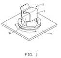
- FIG. 1is an assembled view of an optical fiber holder of the present invention
- FIG. 2is a perspective view of a holding element of the optical fiber holder
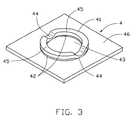
- FIG. 3is a perspective view of a base of the optical fiber holder
- FIG. 4is a perspective, exploded view of FIG. 1;
- FIG. 5is an assembled view of the optical fiber holder with fibers received therein.
- FIG. 6is an assembled view of a fiber holder of the prior art
- an optical fiber holder 2comprises a holding element 3 and a base 4 .
- the holding element 3defines a passageway 34 for containing a plurality of fibers 5 .
- the holding element 3is assembled onto the base 4 and may rotate relative to the base 4 when an outside force acts on the fibers 5 .
- the holding element 3is a single piece and may be formed by stamping and bending a metal sheet.
- the holding element, 3comprises a body 35 , a pair of fixing feet 31 , a bending portion 32 and a side wall 33 .
- the passageway 34is surrounded by the body 35 , the bending portion 32 and the side wall 33 .
- the side wall 33extends upwardly from one side edge (not labeled) of the body 35 .
- a tip portion 331 of the side wall 33inclines outwardly.
- the bending portion 32extends upwardly from an opposite side edge (not labeled) of the body 35 , then bends horizontally at its upper portion.
- the bending portion 32opposes the side wall 33 at its lower half, and opposes the body 35 at its upper half.
- a deflexed portion 321extends downwardly from end of the bending portion 32 and is substantially perpendicular to the body 35 .
- a guide slot(not labeled) is formed between the deflexed portion 321 and the side wall 33 and communicates with the passageway 34 .
- the two fixing feet 31respectively extend outwardly from two opposite end edges of the body 35 , bending first downwardly and then outwardly to form a step shape.
- Each fixing foot 31comprises a fixing portion 311 and a flexible portion 312 .
- the base 4comprises a flat peripheral portion 46 and center portion 43 , and a raised flange 41 .
- the flange 41comprises two camber sections 45 and two connection sections 44 .
- the flange 41protrudes above the rest of the base 4 and can be formed by punching.
- the two camber sections 45connect with the center portion 43 and the peripheral portion 46 through the two connection sections 44 .
- Two slots 42are formed between the two camber sections 45 and the center and peripheral portions 43 , 46 .
- the fixing feet 31 of the holding element 3are pressed inwardly towards each other until the ends of the fixing portions 311 can be inserted into the slots 42 of the base 4 .
- the fixing feet 31are then released, allowing the fixing feet 31 to spring outwardly again, locking the holding element 3 to the base 4 .
- the holding element 3is then rotatable within a fixed range on the base 4 as the fixing portions 311 slide within the slots 42 .
- a plurality of fibers 5are inserted, one by one, through the guide slot (not labeled) and into the passageway 34 of the holding element 3 .
- the deflexed portion 321prevents the fibers 5 from disengaging from the holding element 3 .
- the holding element 3can rotate relative to the base 4 , allowing the fibers 5 to bend more easily when outside forces are exerted on the fibers 5 , thereby protecting the fibers 5 from being damaged.
Landscapes
- Physics & Mathematics (AREA)
- General Physics & Mathematics (AREA)
- Optics & Photonics (AREA)
- Mechanical Coupling Of Light Guides (AREA)
Abstract
Description
1. Field of the Invention
The present invention relates to an optical fiber holder, and particularly to a rotatable optical fiber holder which can rotate within a fixed range when an outside force acts on fibers held within the optical fiber holder.
2. Description of Related Art
Optical fibers that are currently commercially available comprise a central glass core, a glass cladding that surrounds the core, and a coating of synthetic polymer material. The use of optical fibers is increasing for communication. Since optical fibers are thin and fragile, a reliable method of securing the optical fibers along an optical path is necessary.
Presently, traditional wire holders are most used for receiving and holding a plurality of loose fibers in an optical path. These presently used holders are commonly made of a polymer material, and are assembled on a base utilizing glue. These holders tend to be too rigid and wear out too quickly. Furthermore, these present holders can not rotate relatively to the base, so can not turn to reduce the bending of the fibers caused by outside forces acting on the fibers, and thus the fibers are easily damaged.
For example, referring to FIG. 6, Taiwanese Patent No. 311696 discloses a fiber holder comprising abase 11, a slidingblock 12, asliding element 13, and ascrew 14. Thesliding element 13 defines a plurality ofgrooves 131 for receivingoptical fibers 15, and a center hole for receiving thescrew 14. Fibers received in thegrooves 131 are retained in thegrooves 131 by screwing in thescrew 14 until it presses against the fibers. Thefibers 15 are thin and fragile, and are easily damaged when thescrew 14 exerts too much pressure on the fibers. On the other hand, the fibers can easily fall out of thegrooves 131 when the pressure exerted by thescrew 14 on the fibers is too small.
A new optical fiber holder is desired which securely holds fibers without damaging the fibers, and which has a range of rotational movement which allows the fibers to flex under the influence of an outside force without damage to themselves.
An object of the present invention is to provide an improved optical fiber holder, and particularly to provide an optical fiber holder which allows a range of rotational movement of the fibers held therein.
An optical fiber holder of the present invention comprises a holding element and a base. The holding element is assembled onto the base and may rotate relative to the base when an outside force acts on fibers held within the holding element.
The holding element comprises a body, a pair of fixing feet, a bending portion and a side wall. A passageway is defined between the body, the bending portion and the side wall. A tip portion of the side_wall inclines outwardly. A deflexed portion of the bending portion extends downwardly from an end of the bending portion and is substantially perpendicular to the body. A guide slot is formed between the deflexed portion and the side wall and communicates with the passageway. The two fixing feet respectively extend from two opposite ends of the body and are formed in a step shape. Each fixing foot comprises a fixing portion and a flexible portion.
The base comprises a flange, a center portion and a peripheral portion. Two slots are formed between the flange and the center and peripheral portions.
In assembly, the two fixing feet are pressed inward toward each other until each fixing portion of each fixing foot can enter the slot beneath the flange. Pressure is removed from the fixing feet, allowing the fixing feet to spring outward, locking the holding element into the base.
In use, a plurality of fibers are inserted one by one into the passageway of the holding element through the guide slot.
Other objects, advantages, and novel features of the present invention will become more apparent from the following detailed description when taken in conjunction with the accompanying drawings.
FIG. 1 is an assembled view of an optical fiber holder of the present invention;
FIG. 2 is a perspective view of a holding element of the optical fiber holder;
FIG. 3 is a perspective view of a base of the optical fiber holder;
FIG. 4 is a perspective, exploded view of FIG. 1;
FIG. 5 is an assembled view of the optical fiber holder with fibers received therein; and
FIG. 6 is an assembled view of a fiber holder of the prior art;
As shown in FIGS. 1 and 5, an optical fiber holder2 comprises aholding element 3 and abase 4. Theholding element 3 defines apassageway 34 for containing a plurality offibers 5. Theholding element 3 is assembled onto thebase 4 and may rotate relative to thebase 4 when an outside force acts on thefibers 5. Theholding element 3 is a single piece and may be formed by stamping and bending a metal sheet.
As shown in FIG. 2, the holding element,3 comprises abody 35, a pair offixing feet 31, abending portion 32 and aside wall 33. Thepassageway 34 is surrounded by thebody 35, thebending portion 32 and theside wall 33. Theside wall 33 extends upwardly from one side edge (not labeled) of thebody 35. Atip portion 331 of theside wall 33 inclines outwardly. Thebending portion 32 extends upwardly from an opposite side edge (not labeled) of thebody 35, then bends horizontally at its upper portion. Thebending portion 32 opposes theside wall 33 at its lower half, and opposes thebody 35 at its upper half. Adeflexed portion 321 extends downwardly from end of thebending portion 32 and is substantially perpendicular to thebody 35. A guide slot (not labeled) is formed between thedeflexed portion 321 and theside wall 33 and communicates with thepassageway 34. The twofixing feet 31 respectively extend outwardly from two opposite end edges of thebody 35, bending first downwardly and then outwardly to form a step shape. Eachfixing foot 31 comprises afixing portion 311 and aflexible portion 312.
As shown in FIG. 3, thebase 4 comprises a flatperipheral portion 46 andcenter portion 43, and a raisedflange 41. Theflange 41 comprises twocamber sections 45 and twoconnection sections 44. Theflange 41 protrudes above the rest of thebase 4 and can be formed by punching. The twocamber sections 45 connect with thecenter portion 43 and theperipheral portion 46 through the twoconnection sections 44. Twoslots 42 are formed between the twocamber sections 45 and the center andperipheral portions
Referring to FIG. 2, FIG.4 and FIG. 5, in assembly, thefixing feet 31 of theholding element 3 are pressed inwardly towards each other until the ends of thefixing portions 311 can be inserted into theslots 42 of thebase 4. After thefixing portions 311 are engaged with the slots42 (onefixing portion 311 per one slot42), thefixing feet 31 are then released, allowing thefixing feet 31 to spring outwardly again, locking theholding element 3 to thebase 4. The holdingelement 3 is then rotatable within a fixed range on thebase 4 as the fixingportions 311 slide within theslots 42.
In use, a plurality offibers 5 are inserted, one by one, through the guide slot (not labeled) and into thepassageway 34 of the holdingelement 3. Thedeflexed portion 321 prevents thefibers 5 from disengaging from the holdingelement 3. The holdingelement 3 can rotate relative to thebase 4, allowing thefibers 5 to bend more easily when outside forces are exerted on thefibers 5, thereby protecting thefibers 5 from being damaged.
It is to be understood, however, that even though numerous characteristics and advantages of the present invention have been set forth in the foregoing description, together with details of the structure and function of the invention, the disclosure is illustrative only, and changes may be made in detail, especially in matters of shape, size, and arrangement of parts within the principles of the invention to the full extent indicated by the broad general meaning of the terms in which the appended claims are expressed.
Claims (20)
1. An optical fiber holder for holding a plurality of optical fibers, comprising:
a base defining at least one slot;
a holding element assembled on the base, the holding element comprising at least one fixing foot which is received in the at least one slot, the holding element defining a passageway for containing the fibers therein, the holding element being rotatably moveable relative to the base, thereby allowing the fibers to bend more easily when an outside force acts against the fibers.
2. The optical fiber holder as claimed inclaim 1 , wherein the base further comprises a flange, a center portion and a peripheral portion.
3. The optical fiber holder as claimed inclaim 2 , wherein the flange comprises two camber sections and two connection sections.
4. The optical fiber holder as claimed inclaim 3 , wherein the at least one slot is two slots formed between the two camber sections and the center and peripheral portions.
5. The optical fiber holder as claimed inclaim 4 , wherein the at least one fixing foot is two fixing feet extending from two opposite ends of the holding element, and the two fixing feet are received in the slots, one in each slot.
6. The optical fiber holder as claimed inclaim 1 , wherein the holding element comprises a body, a side wall and a bending portion, and the passageway is defined between the body, the side wall and the bending portion.
7. The optical fiber holder as claimed inclaim 6 , wherein the holding element comprises a deflexed portion extending from an end of the bending portion and a tip portion extending outwardly from the sidewall, and a guide slot for admitting entrance of fibers into the passageway is formed between the deflexed portion and the side wall.
8. An optical fiber holder for mounting fibers along an optical path, comprising:
a base;
a holding element assembled to the base, the holding element comprising:
a horizontal body having a first edge and a second edge opposite each other;
a side wall bending and extending upward from the first edge of the body; and
a bending portion bending and extending upward from the second edge of the body, opposed to the side wall, then bending inwardly substantially horizontally, toward the side wall and opposed to the body, then bending downwardly toward the body as a deflexed portion, said deflexed portion being in close proximity to the side wall;
wherein a passageway is defined between the body, the side wall and the bending portion for containing the fibers, and a guide slot is formed between the deflexed portion and the side wall, the guide slot communicates with the passageway, for admitting entrance of one or more fibers into the passageway.
9. The optical fiber holder as claimed inclaim 8 , wherein the base comprises a peripheral portion, a center portion and a flange.
10. The optical fiber holder as claimed inclaim 9 , wherein the flange protrudes above the peripheral and center portions and comprises two connection sections and two camber sections.
11. The optical fiber holder as claimed inclaim 10 , wherein two slots are formed between the two camber sections and the center and peripheral portions.
12. The optical fiber holder as claimed inclaim 11 , wherein the holding element further comprises two fixing feet, which extend from two opposite ends of the body.
13. The optical fiber holder as claimed inclaim 12 , wherein the two fixing feet are receivable in the two slots, and are slidable therein, allowing rotation of the holding element relative to the base when an outside force acts upon the fibers held within the holding element.
14. An optical fiber holder for mounting a plurality of fibers along an optical path, comprising:
a base lying substantially in a plane;
a holding element assembled to the base and rotatable about an axis orthogonal to a plane of the base, the holding element comprising a substantially tubular wall and a mounting element, the mounting element being in rotational engagement with the base, the tubular wall having a hole defined along the axis of the tubular wall, the axis of the tubular wall being perpendicular to the axis of rotation of the holding element, the plurality of fibers being accommodated within the tubular wall with the axis of the fibers being substantially parallel to the axis of the tubular wall.
15. The optical fiber holder as claimed inclaim 14 , wherein the tubular wall of the holding element has a guide slot through the tubular wall, to allow entrance and removal of the fibers.
16. The optical fiber holder as claimed inclaim 15 , wherein the mounting element of the holding element comprises a pair of feet, which rotatably engage with a pair of slots defined in the base.
17. An optical fiber assembly comprising:
a base;
a holding element mounted on the base, said holding element defining fixing feet portions rotatably engaged with the base, a side wall cooperating with a bending portion defining a passageway in communication with an exterior along a longitudinal direction, a guide slot formed in said holding element and communicating said passageway with said exterior in a lateral direction perpendicular to said longitudinal direction; and
at least one optic fiber inserted through said guide slot into the passageway and extending along said longitudinal direction.
18. The assembly as claimed inclaim 17 , wherein a deflexed portion is formed around the guide slot for preventing said at least one fiber from withdrawal from the holding element.
19. The assembly as claimed inclaim 17 , wherein a width of said guide slot is dimensioned not too larger than a diameter of said at least on fiber.
20. The assembly as claimed inclaim 17 , wherein an inclined tip is formed around the guide slot.
Applications Claiming Priority (2)
| Application Number | Priority Date | Filing Date | Title |
|---|---|---|---|
| TW090217383UTW505221U (en) | 2001-10-12 | 2001-10-12 | Fastening apparatus for optical fiber |
| TW90217383U | 2001-10-12 |
Publications (1)
| Publication Number | Publication Date |
|---|---|
| US6510274B1true US6510274B1 (en) | 2003-01-21 |
Family
ID=21686839
Family Applications (1)
| Application Number | Title | Priority Date | Filing Date |
|---|---|---|---|
| US09/994,424Expired - Fee RelatedUS6510274B1 (en) | 2001-10-12 | 2001-11-26 | Optical fiber holder |
Country Status (2)
| Country | Link |
|---|---|
| US (1) | US6510274B1 (en) |
| TW (1) | TW505221U (en) |
Cited By (48)
| Publication number | Priority date | Publication date | Assignee | Title |
|---|---|---|---|---|
| US20030086675A1 (en)* | 2001-11-07 | 2003-05-08 | Kun-Tsan Wu | Rotatable holder |
| US20040086253A1 (en)* | 2002-11-06 | 2004-05-06 | Karras Thomas William | Fiberoptic harness for distribution of signals with stable phase delay |
| US20080237193A1 (en)* | 2007-03-28 | 2008-10-02 | Bogdon Erik R | Electrical switching apparatus, and accessory module and electrical conductor mount therefor |
| US20080287940A1 (en)* | 2007-05-14 | 2008-11-20 | Hunter Lowell D | Fiber Pole Tip |
| US20080287934A1 (en)* | 2007-05-15 | 2008-11-20 | Hunter Lowell D | Laser Handle and Fiber Guard |
| US20090088616A1 (en)* | 2005-05-18 | 2009-04-02 | Hirokazu Atsumori | Ultrasonic Diagnostic Apparatus |
| US20100209064A1 (en)* | 2009-02-18 | 2010-08-19 | Gil Ruiz | Wedge-shaped fiber retainer ring |
| US20110211801A1 (en)* | 2010-03-01 | 2011-09-01 | Mcgranahan Daniel S | Cable Routing Guide With Cable Retainer |
| WO2011137341A1 (en)* | 2010-04-30 | 2011-11-03 | Corning Cable Systems Llc | Rotatable routing guide and assembly for fiber optic cables |
| US8457464B2 (en) | 2011-09-26 | 2013-06-04 | Hubbell Incorporated | Cable enclosure and radius-limiting cable guide with integral magnetic door catch |
| CN103217762A (en)* | 2013-04-15 | 2013-07-24 | 华为机器有限公司 | Fiber outcoming structural component and optical module |
| US8538226B2 (en) | 2009-05-21 | 2013-09-17 | Corning Cable Systems Llc | Fiber optic equipment guides and rails configured with stopping position(s), and related equipment and methods |
| US8542973B2 (en) | 2010-04-23 | 2013-09-24 | Ccs Technology, Inc. | Fiber optic distribution device |
| US8593828B2 (en) | 2010-02-04 | 2013-11-26 | Corning Cable Systems Llc | Communications equipment housings, assemblies, and related alignment features and methods |
| US8625950B2 (en) | 2009-12-18 | 2014-01-07 | Corning Cable Systems Llc | Rotary locking apparatus for fiber optic equipment trays and related methods |
| US8660397B2 (en) | 2010-04-30 | 2014-02-25 | Corning Cable Systems Llc | Multi-layer module |
| US8662760B2 (en) | 2010-10-29 | 2014-03-04 | Corning Cable Systems Llc | Fiber optic connector employing optical fiber guide member |
| US8699838B2 (en) | 2009-05-14 | 2014-04-15 | Ccs Technology, Inc. | Fiber optic furcation module |
| US8705926B2 (en) | 2010-04-30 | 2014-04-22 | Corning Optical Communications LLC | Fiber optic housings having a removable top, and related components and methods |
| US8712206B2 (en) | 2009-06-19 | 2014-04-29 | Corning Cable Systems Llc | High-density fiber optic modules and module housings and related equipment |
| US8718436B2 (en) | 2010-08-30 | 2014-05-06 | Corning Cable Systems Llc | Methods, apparatuses for providing secure fiber optic connections |
| US8770532B2 (en) | 2011-05-13 | 2014-07-08 | Commscope, Inc. Of North Carolina | Cable retaining ring having slide closure and cable support tray including the cable retaining ring |
| US8913866B2 (en) | 2010-03-26 | 2014-12-16 | Corning Cable Systems Llc | Movable adapter panel |
| US8953924B2 (en) | 2011-09-02 | 2015-02-10 | Corning Cable Systems Llc | Removable strain relief brackets for securing fiber optic cables and/or optical fibers to fiber optic equipment, and related assemblies and methods |
| US8965168B2 (en) | 2010-04-30 | 2015-02-24 | Corning Cable Systems Llc | Fiber management devices for fiber optic housings, and related components and methods |
| US8989547B2 (en) | 2011-06-30 | 2015-03-24 | Corning Cable Systems Llc | Fiber optic equipment assemblies employing non-U-width-sized housings and related methods |
| US8985862B2 (en) | 2013-02-28 | 2015-03-24 | Corning Cable Systems Llc | High-density multi-fiber adapter housings |
| US20150086170A1 (en)* | 2013-09-20 | 2015-03-26 | Adva Optical Networking Se | Fiber Optic Component Holding Device |
| US8995812B2 (en) | 2012-10-26 | 2015-03-31 | Ccs Technology, Inc. | Fiber optic management unit and fiber optic distribution device |
| US9008485B2 (en) | 2011-05-09 | 2015-04-14 | Corning Cable Systems Llc | Attachment mechanisms employed to attach a rear housing section to a fiber optic housing, and related assemblies and methods |
| US9020320B2 (en) | 2008-08-29 | 2015-04-28 | Corning Cable Systems Llc | High density and bandwidth fiber optic apparatuses and related equipment and methods |
| US9022814B2 (en) | 2010-04-16 | 2015-05-05 | Ccs Technology, Inc. | Sealing and strain relief device for data cables |
| US9042702B2 (en) | 2012-09-18 | 2015-05-26 | Corning Cable Systems Llc | Platforms and systems for fiber optic cable attachment |
| US9038832B2 (en) | 2011-11-30 | 2015-05-26 | Corning Cable Systems Llc | Adapter panel support assembly |
| US9059578B2 (en) | 2009-02-24 | 2015-06-16 | Ccs Technology, Inc. | Holding device for a cable or an assembly for use with a cable |
| US9075217B2 (en) | 2010-04-30 | 2015-07-07 | Corning Cable Systems Llc | Apparatuses and related components and methods for expanding capacity of fiber optic housings |
| US9116324B2 (en) | 2010-10-29 | 2015-08-25 | Corning Cable Systems Llc | Stacked fiber optic modules and fiber optic equipment configured to support stacked fiber optic modules |
| US9213161B2 (en) | 2010-11-05 | 2015-12-15 | Corning Cable Systems Llc | Fiber body holder and strain relief device |
| US9250409B2 (en) | 2012-07-02 | 2016-02-02 | Corning Cable Systems Llc | Fiber-optic-module trays and drawers for fiber-optic equipment |
| US9279951B2 (en) | 2010-10-27 | 2016-03-08 | Corning Cable Systems Llc | Fiber optic module for limited space applications having a partially sealed module sub-assembly |
| US9519118B2 (en) | 2010-04-30 | 2016-12-13 | Corning Optical Communications LLC | Removable fiber management sections for fiber optic housings, and related components and methods |
| US9632270B2 (en) | 2010-04-30 | 2017-04-25 | Corning Optical Communications LLC | Fiber optic housings configured for tool-less assembly, and related components and methods |
| US9645317B2 (en) | 2011-02-02 | 2017-05-09 | Corning Optical Communications LLC | Optical backplane extension modules, and related assemblies suitable for establishing optical connections to information processing modules disposed in equipment racks |
| US9720195B2 (en) | 2010-04-30 | 2017-08-01 | Corning Optical Communications LLC | Apparatuses and related components and methods for attachment and release of fiber optic housings to and from an equipment rack |
| AU2015224450B2 (en)* | 2010-04-30 | 2017-10-12 | Corning Optical Communications LLC | Rotatable routing guide and assembly for fiber optic cables |
| US10094996B2 (en) | 2008-08-29 | 2018-10-09 | Corning Optical Communications, Llc | Independently translatable modules and fiber optic equipment trays in fiber optic equipment |
| US20180364435A1 (en)* | 2014-09-16 | 2018-12-20 | CommScope Connectivity Belgium BVBA | Rotatable patch cable holder |
| US11294136B2 (en) | 2008-08-29 | 2022-04-05 | Corning Optical Communications LLC | High density and bandwidth fiber optic apparatuses and related equipment and methods |
Citations (3)
| Publication number | Priority date | Publication date | Assignee | Title |
|---|---|---|---|---|
| US5044721A (en)* | 1989-04-18 | 1991-09-03 | Amp Incorporated | Holder for optical fiber end-processing device |
| US5530785A (en)* | 1993-12-28 | 1996-06-25 | Fujitsu Limited | Optical fiber cable fixing structure and cable holder used for fixing the cable |
| US6324331B1 (en)* | 1999-01-14 | 2001-11-27 | Corning Incorporated | Passive platform for holding optical components |
- 2001
- 2001-10-12TWTW090217383Upatent/TW505221U/ennot_activeIP Right Cessation
- 2001-11-26USUS09/994,424patent/US6510274B1/ennot_activeExpired - Fee Related
Patent Citations (3)
| Publication number | Priority date | Publication date | Assignee | Title |
|---|---|---|---|---|
| US5044721A (en)* | 1989-04-18 | 1991-09-03 | Amp Incorporated | Holder for optical fiber end-processing device |
| US5530785A (en)* | 1993-12-28 | 1996-06-25 | Fujitsu Limited | Optical fiber cable fixing structure and cable holder used for fixing the cable |
| US6324331B1 (en)* | 1999-01-14 | 2001-11-27 | Corning Incorporated | Passive platform for holding optical components |
Cited By (80)
| Publication number | Priority date | Publication date | Assignee | Title |
|---|---|---|---|---|
| US6771872B2 (en)* | 2001-11-07 | 2004-08-03 | Hon Hai Precision Ind. Co., Ltd. | Rotatable holder |
| US20030086675A1 (en)* | 2001-11-07 | 2003-05-08 | Kun-Tsan Wu | Rotatable holder |
| US20040086253A1 (en)* | 2002-11-06 | 2004-05-06 | Karras Thomas William | Fiberoptic harness for distribution of signals with stable phase delay |
| US8229531B2 (en)* | 2005-05-18 | 2012-07-24 | Hitachi Medical Corporation | Optical bioinstrumentation devices |
| US20090088616A1 (en)* | 2005-05-18 | 2009-04-02 | Hirokazu Atsumori | Ultrasonic Diagnostic Apparatus |
| US20080237193A1 (en)* | 2007-03-28 | 2008-10-02 | Bogdon Erik R | Electrical switching apparatus, and accessory module and electrical conductor mount therefor |
| US7645953B2 (en)* | 2007-03-28 | 2010-01-12 | Eaton Corporation | Electrical switching apparatus, and accessory module and electrical conductor mount therefor |
| EP1975965A3 (en)* | 2007-03-28 | 2010-03-24 | EATON Corporation | Electrical switching apparatus, and accessory module and electrical conductor mount therefor |
| CN101354989B (en)* | 2007-03-28 | 2013-01-02 | 伊顿公司 | Electrical switching apparatus, and accessory module and electrical conductor mount thereof |
| US20080287940A1 (en)* | 2007-05-14 | 2008-11-20 | Hunter Lowell D | Fiber Pole Tip |
| US20080287934A1 (en)* | 2007-05-15 | 2008-11-20 | Hunter Lowell D | Laser Handle and Fiber Guard |
| US8419718B2 (en)* | 2007-05-15 | 2013-04-16 | Ams Research Corporation | Laser handle and fiber guard |
| US11092767B2 (en) | 2008-08-29 | 2021-08-17 | Corning Optical Communications LLC | High density and bandwidth fiber optic apparatuses and related equipment and methods |
| US11086089B2 (en) | 2008-08-29 | 2021-08-10 | Corning Optical Communications LLC | High density and bandwidth fiber optic apparatuses and related equipment and methods |
| US11754796B2 (en) | 2008-08-29 | 2023-09-12 | Corning Optical Communications LLC | Independently translatable modules and fiber optic equipment trays in fiber optic equipment |
| US12072545B2 (en) | 2008-08-29 | 2024-08-27 | Corning Optical Communications LLC | High density and bandwidth fiber optic apparatuses and related equipment and methods |
| US11294135B2 (en) | 2008-08-29 | 2022-04-05 | Corning Optical Communications LLC | High density and bandwidth fiber optic apparatuses and related equipment and methods |
| US10126514B2 (en) | 2008-08-29 | 2018-11-13 | Corning Optical Communications, Llc | Independently translatable modules and fiber optic equipment trays in fiber optic equipment |
| US11294136B2 (en) | 2008-08-29 | 2022-04-05 | Corning Optical Communications LLC | High density and bandwidth fiber optic apparatuses and related equipment and methods |
| US10222570B2 (en) | 2008-08-29 | 2019-03-05 | Corning Optical Communications LLC | Independently translatable modules and fiber optic equipment trays in fiber optic equipment |
| US9020320B2 (en) | 2008-08-29 | 2015-04-28 | Corning Cable Systems Llc | High density and bandwidth fiber optic apparatuses and related equipment and methods |
| US10416405B2 (en) | 2008-08-29 | 2019-09-17 | Corning Optical Communications LLC | Independently translatable modules and fiber optic equipment trays in fiber optic equipment |
| US9910236B2 (en) | 2008-08-29 | 2018-03-06 | Corning Optical Communications LLC | High density and bandwidth fiber optic apparatuses and related equipment and methods |
| US10120153B2 (en) | 2008-08-29 | 2018-11-06 | Corning Optical Communications, Llc | Independently translatable modules and fiber optic equipment trays in fiber optic equipment |
| US10852499B2 (en) | 2008-08-29 | 2020-12-01 | Corning Optical Communications LLC | High density and bandwidth fiber optic apparatuses and related equipment and methods |
| US11609396B2 (en) | 2008-08-29 | 2023-03-21 | Corning Optical Communications LLC | High density and bandwidth fiber optic apparatuses and related equipment and methods |
| US10606014B2 (en) | 2008-08-29 | 2020-03-31 | Corning Optical Communications LLC | Independently translatable modules and fiber optic equipment trays in fiber optic equipment |
| US10094996B2 (en) | 2008-08-29 | 2018-10-09 | Corning Optical Communications, Llc | Independently translatable modules and fiber optic equipment trays in fiber optic equipment |
| US10564378B2 (en) | 2008-08-29 | 2020-02-18 | Corning Optical Communications LLC | High density and bandwidth fiber optic apparatuses and related equipment and methods |
| US10459184B2 (en) | 2008-08-29 | 2019-10-29 | Corning Optical Communications LLC | High density and bandwidth fiber optic apparatuses and related equipment and methods |
| US10444456B2 (en) | 2008-08-29 | 2019-10-15 | Corning Optical Communications LLC | High density and bandwidth fiber optic apparatuses and related equipment and methods |
| US10422971B2 (en) | 2008-08-29 | 2019-09-24 | Corning Optical Communicatinos LLC | High density and bandwidth fiber optic apparatuses and related equipment and methods |
| US20100209064A1 (en)* | 2009-02-18 | 2010-08-19 | Gil Ruiz | Wedge-shaped fiber retainer ring |
| US8472776B2 (en)* | 2009-02-18 | 2013-06-25 | Commscope, Inc. Of North Carolina | Wedge shaped fiber retainer ring |
| US9059578B2 (en) | 2009-02-24 | 2015-06-16 | Ccs Technology, Inc. | Holding device for a cable or an assembly for use with a cable |
| US8699838B2 (en) | 2009-05-14 | 2014-04-15 | Ccs Technology, Inc. | Fiber optic furcation module |
| US9075216B2 (en) | 2009-05-21 | 2015-07-07 | Corning Cable Systems Llc | Fiber optic housings configured to accommodate fiber optic modules/cassettes and fiber optic panels, and related components and methods |
| US8538226B2 (en) | 2009-05-21 | 2013-09-17 | Corning Cable Systems Llc | Fiber optic equipment guides and rails configured with stopping position(s), and related equipment and methods |
| US8712206B2 (en) | 2009-06-19 | 2014-04-29 | Corning Cable Systems Llc | High-density fiber optic modules and module housings and related equipment |
| US8625950B2 (en) | 2009-12-18 | 2014-01-07 | Corning Cable Systems Llc | Rotary locking apparatus for fiber optic equipment trays and related methods |
| US8593828B2 (en) | 2010-02-04 | 2013-11-26 | Corning Cable Systems Llc | Communications equipment housings, assemblies, and related alignment features and methods |
| US8992099B2 (en) | 2010-02-04 | 2015-03-31 | Corning Cable Systems Llc | Optical interface cards, assemblies, and related methods, suited for installation and use in antenna system equipment |
| US20110211801A1 (en)* | 2010-03-01 | 2011-09-01 | Mcgranahan Daniel S | Cable Routing Guide With Cable Retainer |
| US8913866B2 (en) | 2010-03-26 | 2014-12-16 | Corning Cable Systems Llc | Movable adapter panel |
| US9022814B2 (en) | 2010-04-16 | 2015-05-05 | Ccs Technology, Inc. | Sealing and strain relief device for data cables |
| US8542973B2 (en) | 2010-04-23 | 2013-09-24 | Ccs Technology, Inc. | Fiber optic distribution device |
| US8705926B2 (en) | 2010-04-30 | 2014-04-22 | Corning Optical Communications LLC | Fiber optic housings having a removable top, and related components and methods |
| US9075217B2 (en) | 2010-04-30 | 2015-07-07 | Corning Cable Systems Llc | Apparatuses and related components and methods for expanding capacity of fiber optic housings |
| US8660397B2 (en) | 2010-04-30 | 2014-02-25 | Corning Cable Systems Llc | Multi-layer module |
| US8965168B2 (en) | 2010-04-30 | 2015-02-24 | Corning Cable Systems Llc | Fiber management devices for fiber optic housings, and related components and methods |
| US20110268413A1 (en)* | 2010-04-30 | 2011-11-03 | Cote Monique L | Rotatable Routing Guide and Assembly |
| US9519118B2 (en) | 2010-04-30 | 2016-12-13 | Corning Optical Communications LLC | Removable fiber management sections for fiber optic housings, and related components and methods |
| US9632270B2 (en) | 2010-04-30 | 2017-04-25 | Corning Optical Communications LLC | Fiber optic housings configured for tool-less assembly, and related components and methods |
| US9720195B2 (en) | 2010-04-30 | 2017-08-01 | Corning Optical Communications LLC | Apparatuses and related components and methods for attachment and release of fiber optic housings to and from an equipment rack |
| AU2015224450B2 (en)* | 2010-04-30 | 2017-10-12 | Corning Optical Communications LLC | Rotatable routing guide and assembly for fiber optic cables |
| US8879881B2 (en)* | 2010-04-30 | 2014-11-04 | Corning Cable Systems Llc | Rotatable routing guide and assembly |
| WO2011137341A1 (en)* | 2010-04-30 | 2011-11-03 | Corning Cable Systems Llc | Rotatable routing guide and assembly for fiber optic cables |
| US8718436B2 (en) | 2010-08-30 | 2014-05-06 | Corning Cable Systems Llc | Methods, apparatuses for providing secure fiber optic connections |
| US9279951B2 (en) | 2010-10-27 | 2016-03-08 | Corning Cable Systems Llc | Fiber optic module for limited space applications having a partially sealed module sub-assembly |
| US9116324B2 (en) | 2010-10-29 | 2015-08-25 | Corning Cable Systems Llc | Stacked fiber optic modules and fiber optic equipment configured to support stacked fiber optic modules |
| US8662760B2 (en) | 2010-10-29 | 2014-03-04 | Corning Cable Systems Llc | Fiber optic connector employing optical fiber guide member |
| US9213161B2 (en) | 2010-11-05 | 2015-12-15 | Corning Cable Systems Llc | Fiber body holder and strain relief device |
| US10481335B2 (en) | 2011-02-02 | 2019-11-19 | Corning Optical Communications, Llc | Dense shuttered fiber optic connectors and assemblies suitable for establishing optical connections for optical backplanes in equipment racks |
| US9645317B2 (en) | 2011-02-02 | 2017-05-09 | Corning Optical Communications LLC | Optical backplane extension modules, and related assemblies suitable for establishing optical connections to information processing modules disposed in equipment racks |
| US9008485B2 (en) | 2011-05-09 | 2015-04-14 | Corning Cable Systems Llc | Attachment mechanisms employed to attach a rear housing section to a fiber optic housing, and related assemblies and methods |
| US8770532B2 (en) | 2011-05-13 | 2014-07-08 | Commscope, Inc. Of North Carolina | Cable retaining ring having slide closure and cable support tray including the cable retaining ring |
| US8989547B2 (en) | 2011-06-30 | 2015-03-24 | Corning Cable Systems Llc | Fiber optic equipment assemblies employing non-U-width-sized housings and related methods |
| US8953924B2 (en) | 2011-09-02 | 2015-02-10 | Corning Cable Systems Llc | Removable strain relief brackets for securing fiber optic cables and/or optical fibers to fiber optic equipment, and related assemblies and methods |
| US8457464B2 (en) | 2011-09-26 | 2013-06-04 | Hubbell Incorporated | Cable enclosure and radius-limiting cable guide with integral magnetic door catch |
| US9038832B2 (en) | 2011-11-30 | 2015-05-26 | Corning Cable Systems Llc | Adapter panel support assembly |
| US9250409B2 (en) | 2012-07-02 | 2016-02-02 | Corning Cable Systems Llc | Fiber-optic-module trays and drawers for fiber-optic equipment |
| US9042702B2 (en) | 2012-09-18 | 2015-05-26 | Corning Cable Systems Llc | Platforms and systems for fiber optic cable attachment |
| US8995812B2 (en) | 2012-10-26 | 2015-03-31 | Ccs Technology, Inc. | Fiber optic management unit and fiber optic distribution device |
| US8985862B2 (en) | 2013-02-28 | 2015-03-24 | Corning Cable Systems Llc | High-density multi-fiber adapter housings |
| CN103217762A (en)* | 2013-04-15 | 2013-07-24 | 华为机器有限公司 | Fiber outcoming structural component and optical module |
| US10061089B2 (en)* | 2013-09-20 | 2018-08-28 | Adva Optical Networking Se | Fiber optic component holding device for fibers in side-by-side contact |
| US20150086170A1 (en)* | 2013-09-20 | 2015-03-26 | Adva Optical Networking Se | Fiber Optic Component Holding Device |
| US10627591B2 (en)* | 2014-09-16 | 2020-04-21 | CommScope Connectivity Belgium BVBA | Rotatable patch cable holder |
| US11448843B2 (en) | 2014-09-16 | 2022-09-20 | CommScope Connectivity Belgium BVBA | Rotatable patch cable holder |
| US20180364435A1 (en)* | 2014-09-16 | 2018-12-20 | CommScope Connectivity Belgium BVBA | Rotatable patch cable holder |
Also Published As
| Publication number | Publication date |
|---|---|
| TW505221U (en) | 2002-10-01 |
Similar Documents
| Publication | Publication Date | Title |
|---|---|---|
| US6510274B1 (en) | Optical fiber holder | |
| JP4099228B2 (en) | Fiber optic connector for fibers having cleaved / chamfered ends | |
| AU635172B2 (en) | Multifiber optical connector plug with low reflection and low insertion loss | |
| US7204644B2 (en) | Field installable optical fiber connector | |
| US6224268B1 (en) | Plug housing with attached cantilevered latch for a fiber optic connector | |
| US7104702B2 (en) | Field installable optical fiber connector | |
| US6019521A (en) | Optical fiber connector | |
| JP4900893B2 (en) | Small form factor field mountable connector | |
| JP5865370B2 (en) | Assembly tool and optical fiber connector assembly method | |
| US8875403B2 (en) | Coating removal tool used for optical fiber and method of removing coating | |
| US20030068061A1 (en) | Receptacle for earphone cord | |
| US20030007743A1 (en) | Optical connector | |
| US5675660A (en) | Apparatus for protecting microphones | |
| US20030086675A1 (en) | Rotatable holder | |
| EP1237023A3 (en) | Ferrule holding structure for optical connector component | |
| CA2488350A1 (en) | Optical connector readily capable connecting an optical fiber without damaging the optical fiber | |
| US7001084B2 (en) | Fiber splice device | |
| US20040052493A1 (en) | Optical fiber retaining clip | |
| US11740413B1 (en) | Duplex optical connector with laterally repositionable connectors and pull boot release | |
| US20030086676A1 (en) | Optical fiber cable holder | |
| US20110038592A1 (en) | Optical fiber adapter | |
| EP0831348A3 (en) | Optical connector | |
| US6654537B2 (en) | Optical fiber holder assembly | |
| US8920050B2 (en) | Termination assembly for alignment of optical fibers | |
| US6481662B1 (en) | Fiber optic cable winding assist tool |
Legal Events
| Date | Code | Title | Description |
|---|---|---|---|
| AS | Assignment | Owner name:NON HAI PRECISION IND., CO., LTD., TAIWAN Free format text:ASSIGNMENT OF ASSIGNORS INTEREST;ASSIGNORS:WU, KUN-TSAN;CHIANG, TSUNG WEI;REEL/FRAME:012334/0289 Effective date:20011105 | |
| REMI | Maintenance fee reminder mailed | ||
| REIN | Reinstatement after maintenance fee payment confirmed | ||
| FP | Lapsed due to failure to pay maintenance fee | Effective date:20070121 | |
| FEPP | Fee payment procedure | Free format text:PETITION RELATED TO MAINTENANCE FEES FILED (ORIGINAL EVENT CODE: PMFP); ENTITY STATUS OF PATENT OWNER: LARGE ENTITY | |
| FEPP | Fee payment procedure | Free format text:PETITION RELATED TO MAINTENANCE FEES GRANTED (ORIGINAL EVENT CODE: PMFG); ENTITY STATUS OF PATENT OWNER: LARGE ENTITY | |
| FPAY | Fee payment | Year of fee payment:4 | |
| SULP | Surcharge for late payment | ||
| PRDP | Patent reinstated due to the acceptance of a late maintenance fee | Effective date:20080514 | |
| REMI | Maintenance fee reminder mailed | ||
| LAPS | Lapse for failure to pay maintenance fees | ||
| STCH | Information on status: patent discontinuation | Free format text:PATENT EXPIRED DUE TO NONPAYMENT OF MAINTENANCE FEES UNDER 37 CFR 1.362 | |
| FP | Lapsed due to failure to pay maintenance fee | Effective date:20110121 |