US6509588B1 - Method for interconnecting anodes and cathodes in a flat capacitor - Google Patents
Method for interconnecting anodes and cathodes in a flat capacitorDownload PDFInfo
- Publication number
- US6509588B1 US6509588B1US09/706,519US70651900AUS6509588B1US 6509588 B1US6509588 B1US 6509588B1US 70651900 AUS70651900 AUS 70651900AUS 6509588 B1US6509588 B1US 6509588B1
- Authority
- US
- United States
- Prior art keywords
- anode
- capacitor
- cathode
- layer
- conductive interconnect
- Prior art date
- Legal status (The legal status is an assumption and is not a legal conclusion. Google has not performed a legal analysis and makes no representation as to the accuracy of the status listed.)
- Expired - Lifetime
Links
- 239000003990capacitorSubstances0.000titleclaimsabstractdescription96
- 238000000034methodMethods0.000titleabstractdescription35
- XAGFODPZIPBFFR-UHFFFAOYSA-NaluminiumChemical group[Al]XAGFODPZIPBFFR-UHFFFAOYSA-N0.000claimsdescription13
- 229910052782aluminiumInorganic materials0.000claimsdescription11
- 239000004593EpoxySubstances0.000claimsdescription2
- 239000004642PolyimideSubstances0.000claimsdescription2
- 229920001940conductive polymerPolymers0.000claimsdescription2
- 229920001721polyimidePolymers0.000claimsdescription2
- 239000011888foilSubstances0.000abstractdescription95
- 239000010410layerSubstances0.000description39
- 238000003466weldingMethods0.000description11
- 229910052751metalInorganic materials0.000description9
- 239000002184metalSubstances0.000description9
- 238000000926separation methodMethods0.000description6
- 238000005530etchingMethods0.000description4
- 150000002739metalsChemical class0.000description4
- 239000000123paperSubstances0.000description4
- LYCAIKOWRPUZTN-UHFFFAOYSA-NEthylene glycolChemical compoundOCCOLYCAIKOWRPUZTN-UHFFFAOYSA-N0.000description3
- RTAQQCXQSZGOHL-UHFFFAOYSA-NTitaniumChemical compound[Ti]RTAQQCXQSZGOHL-UHFFFAOYSA-N0.000description3
- QCWXUUIWCKQGHC-UHFFFAOYSA-NZirconiumChemical compound[Zr]QCWXUUIWCKQGHC-UHFFFAOYSA-N0.000description3
- 239000003792electrolyteSubstances0.000description3
- 229910052735hafniumInorganic materials0.000description3
- VBJZVLUMGGDVMO-UHFFFAOYSA-Nhafnium atomChemical compound[Hf]VBJZVLUMGGDVMO-UHFFFAOYSA-N0.000description3
- 238000004519manufacturing processMethods0.000description3
- 239000000463materialSubstances0.000description3
- 238000012544monitoring processMethods0.000description3
- 229910052758niobiumInorganic materials0.000description3
- 239000010955niobiumSubstances0.000description3
- GUCVJGMIXFAOAE-UHFFFAOYSA-Nniobium atomChemical compound[Nb]GUCVJGMIXFAOAE-UHFFFAOYSA-N0.000description3
- 238000012545processingMethods0.000description3
- 229910052715tantalumInorganic materials0.000description3
- GUVRBAGPIYLISA-UHFFFAOYSA-Ntantalum atomChemical compound[Ta]GUVRBAGPIYLISA-UHFFFAOYSA-N0.000description3
- 229910052719titaniumInorganic materials0.000description3
- 239000010936titaniumSubstances0.000description3
- 229910052726zirconiumInorganic materials0.000description3
- 239000000853adhesiveSubstances0.000description2
- 230000001070adhesive effectEffects0.000description2
- WNLRTRBMVRJNCN-UHFFFAOYSA-Nadipic acidChemical compoundOC(=O)CCCCC(O)=OWNLRTRBMVRJNCN-UHFFFAOYSA-N0.000description2
- 239000004020conductorSubstances0.000description2
- 238000005520cutting processMethods0.000description2
- 230000000694effectsEffects0.000description2
- 238000004146energy storageMethods0.000description2
- 238000002513implantationMethods0.000description2
- 239000002655kraft paperSubstances0.000description2
- 238000003698laser cuttingMethods0.000description2
- 230000000873masking effectEffects0.000description2
- 239000000203mixtureSubstances0.000description2
- 230000033764rhythmic processEffects0.000description2
- 206010007559Cardiac failure congestiveDiseases0.000description1
- 206010019280Heart failuresDiseases0.000description1
- OTRAYOBSWCVTIN-UHFFFAOYSA-NOB(O)O.OB(O)O.OB(O)O.OB(O)O.OB(O)O.N.N.N.N.N.N.N.N.N.N.N.N.N.N.NChemical compoundOB(O)O.OB(O)O.OB(O)O.OB(O)O.OB(O)O.N.N.N.N.N.N.N.N.N.N.N.N.N.N.NOTRAYOBSWCVTIN-UHFFFAOYSA-N0.000description1
- 229920000388PolyphosphatePolymers0.000description1
- 230000002159abnormal effectEffects0.000description1
- 238000004026adhesive bondingMethods0.000description1
- 235000011037adipic acidNutrition0.000description1
- 239000001361adipic acidSubstances0.000description1
- 230000000747cardiac effectEffects0.000description1
- 239000010406cathode materialSubstances0.000description1
- 239000000919ceramicSubstances0.000description1
- 238000010276constructionMethods0.000description1
- 230000007547defectEffects0.000description1
- 238000013461designMethods0.000description1
- 238000010586diagramMethods0.000description1
- 229940093476ethylene glycolDrugs0.000description1
- 239000007943implantSubstances0.000description1
- 238000003780insertionMethods0.000description1
- 230000037431insertionEffects0.000description1
- 239000012212insulatorSubstances0.000description1
- 238000007726management methodMethods0.000description1
- 210000004165myocardiumAnatomy0.000description1
- 239000012811non-conductive materialSubstances0.000description1
- 239000004033plasticSubstances0.000description1
- 239000001205polyphosphateSubstances0.000description1
- 235000011176polyphosphatesNutrition0.000description1
- 238000004080punchingMethods0.000description1
- 239000002356single layerSubstances0.000description1
- 238000005476solderingMethods0.000description1
- 239000000126substanceSubstances0.000description1
- 230000001225therapeutic effectEffects0.000description1
- 238000002560therapeutic procedureMethods0.000description1
- 230000007704transitionEffects0.000description1
- 238000005493welding typeMethods0.000description1
Images


Classifications
- H—ELECTRICITY
- H01—ELECTRIC ELEMENTS
- H01G—CAPACITORS; CAPACITORS, RECTIFIERS, DETECTORS, SWITCHING DEVICES, LIGHT-SENSITIVE OR TEMPERATURE-SENSITIVE DEVICES OF THE ELECTROLYTIC TYPE
- H01G9/00—Electrolytic capacitors, rectifiers, detectors, switching devices, light-sensitive or temperature-sensitive devices; Processes of their manufacture
- H01G9/004—Details
- H01G9/008—Terminals
- A—HUMAN NECESSITIES
- A61—MEDICAL OR VETERINARY SCIENCE; HYGIENE
- A61N—ELECTROTHERAPY; MAGNETOTHERAPY; RADIATION THERAPY; ULTRASOUND THERAPY
- A61N1/00—Electrotherapy; Circuits therefor
- A61N1/18—Applying electric currents by contact electrodes
- A61N1/32—Applying electric currents by contact electrodes alternating or intermittent currents
- A61N1/38—Applying electric currents by contact electrodes alternating or intermittent currents for producing shock effects
- A61N1/39—Heart defibrillators
- A61N1/3956—Implantable devices for applying electric shocks to the heart, e.g. for cardioversion
Definitions
- the present inventionconcerns implantable medical devices, such as defibrillators and cardioverters, particularly structures and methods for capacitors in such devices.
- Capacitorshave undergone substantial improvement over the years. Smaller capacitors are in demand for various applications. One such application is for biomedical implants. For example, defibrillators and pacemakers use capacitors for pulse delivery.
- the defibrillator or cardioverterincludes a set of electrical leads, which extend from a sealed housing into the walls of a heart after implantation. Within the housing are a battery for supplying power, monitoring circuitry for detecting abnormal heart rhythms, and a capacitor for delivering bursts of electric current through the leads to the heart.
- the capacitorcan take the form of a flat aluminum electrolytic capacitor.
- Flat capacitorsinclude a stack of flat capacitor elements mounted within a capacitor case. Each flat capacitor element includes one or more separators between two, sheets of aluminum foil. One of the aluminum foils serves as a cathode (negative) foil, and the other serves as an anode (positive) foil.
- the capacitor elementseach have an individual capacitance (or energy-storage capacity) proportional to the surface area of the foil.
- each of the anodes and each of the cathodesmust be connected together. For instance, all the anodes are crimped or welded together and attached to a feedthrough terminal for connection to circuitry outside the capacitor case. Another process is also done for the cathode foils in the capacitor stack. Errors during the manufacturing steps may cause defects in the capacitor or decrease the reliability of the capacitor after it is constructed. Another drawback is that the interconnections take up space within the capacitor. This increases the size of the capacitor, which is undesirable when the capacitors are used for implantable medical devices such as defibrillators.
- a methodincludes connecting together one or more anode connection members of one or more anode foils and one or more cathode connection members of one or more cathode foils and electrically isolating the one or more anode foils from the one or more cathode foils.
- the methodreduces the processing steps for interconnecting the foils of a capacitor, and provides a capacitor having a smaller amount of room taken up by its interconnections.
- a capacitorhaving a first anode layer, a second anode layer, a cathode layer between the first anode layer and the second anode layer, a first separator layer between the first anode layer and the cathode layer, a second separator layer between the second anode layer and the cathode layer; and a conductive interconnect between the first anode layer and the second anode layer, the conductive interconnect passing through a cathode hole in the cathode; wherein the conductive interconnect has a cross section which is smaller than the cathode hole and the conductive interconnect is placed to avoid direct electrical contact with the cathode layer and wherein the first anode and the second anode are electrically connected through the conductive interconnect.
- Another aspect of the present inventionincludes various implantable medical devices, such as pacemakers, defibrillators, and cardioverters, incorporating one or more capacitors having one or more of the novel features described above.
- implantable medical devicessuch as pacemakers, defibrillators, and cardioverters, incorporating one or more capacitors having one or more of the novel features described above.
- FIG. 1is an isometric view of a flat capacitor according to one embodiment of the present invention.
- FIG. 2Ais a top view of an anode foil for use in constructing a capacitor according to one embodiment of the present invention.
- FIG. 2Bis a top view of a cathode foil for use in constructing a capacitor according to one embodiment of the present invention.
- FIG. 3Ais a top view of an anode foil for use in constructing a capacitor according to one embodiment of the present invention.
- FIG. 3Bis a top view of a cathode foil for use in constructing a capacitor according to one embodiment of the present invention.
- FIG. 4is a perspective view of a stack of one or more anodes and cathodes of FIGS. 2A and 2B.
- FIG. 5is a perspective view of the stack of FIG. 4 after the stack has been processed according to one embodiment of the present invention.
- FIG. 6is a flowchart depicting a method of interconnecting anodes and cathode foils of a capacitor according to one embodiment of the present invention.
- FIG. 7shows a top view of a capacitor stack according to one embodiment.
- FIG. 8shows a cross-section of a portion of FIG. 7 .
- FIG. 9shows a partially etched anode foil according to one embodiment.
- FIG. 10shows a side view of a foil having masks according to one embodiment.
- FIG. 11show a top view of FIG. 10 .
- FIG. 12shows a method according to one embodiment.
- FIG. 13is a block diagram of a generic implantable medical device including a capacitor according to one embodiment of the present invention.
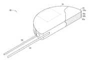
- FIG. 1shows a flat capacitor 100 constructed according to one embodiment of the present invention.
- capacitor 100is a D-shaped capacitor, in other embodiments, the capacitor is another desirable shape, including, but not limited to rectangular, circular, oval or other symmetrical or asymmetrical shape.
- Capacitor 100includes a case 101 which contains a capacitor stack 102 .
- case 101is manufactured from a conductive material, such as aluminum.
- the caseis manufactured using a nonconductive material, such as a ceramic or a plastic.
- Capacitor 100includes a first terminal 103 and a second terminal 104 for connecting capacitor stack 102 to an outside electrical component, such as heart monitor circuitry, including defibrillator, cardioverter, and pacemaker circuitry.
- terminal 103is a feedthrough terminal insulated from case 101
- terminal 104is directly connected to case 101 .
- the capacitorincorporates other connection methods, depending on other design factors.
- capacitor 100includes two or more feedthrough terminals 103 .
- Capacitor stack 102includes capacitor elements 105 a, 105 b, 105 c, . . . , 105 n, with each capacitor element 105 a - 105 n including one or more cathodes, anodes, and separators.
- Each cathodeis a foil structure and can include aluminum, tantalum, hafnium, niobium, titanium, zirconium, and combinations of these metals.
- each cathode of capacitor stack 102is connected to the other cathodes by welding or other connection methods which will be discussed below.
- the cathodesare coupled to conductive case 101 , and terminal 104 is attached to case 101 to provide a cathode connection to outside circuitry.
- the cathodeis coupled to a feedthrough conductor extending through a feedthrough hole.
- the separatoris located between each anode and cathode.
- the separatorincludes one or more sheets of kraft paper impregnated with an electrolyte.
- the separatorincludes two sheets of paper.
- the electrolytecan be any suitable electrolyte for an electrolytic capacitor, such as an ethylene-glycol base combined with polyphosphates, ammonium pentaborate, and/or an adipic acid solute.
- one or more of the anodes of capacitor stack 102is a multi-anode stack which includes three foil layers.
- one or more anode stacksinclude one, two, three or more anode foils having a variety of anode shapes.
- the anode foilsare generally foil structures and can include aluminum, tantalum, hafnium, niobium, titanium, zirconium, and combinations of these metals.
- at least portions of a major surface of each anode foilis roughened or etched to increase its effective surface area. This increases the capacitive effect of the foil with no relative increase in volume.
- Other embodimentsincorporate other foil compositions and/or classes of foil compositions.
- each anodeis connected to the other anodes of the capacitor and coupled to feedthrough assembly 103 for electrically connecting the anode to circuitry outside the case.
- the anodesare connected to the case and the cathodes are coupled to a feedthrough assembly.
- both the anode and the cathodeare connected to feedthroughs.
- FIG. 2Ashows an anode 202 according to one embodiment of the present invention.
- Anode 202is shown before it is assembled into capacitor stack 102 as shown in FIG. 1 .
- Anode 202includes a main body portion 204 having one or more connection members 206 .
- connection member 206includes one or more separate members attached to the anode by welding, staking, or other connection method.
- connection member 206is an integral portion of anode 202 , and is punched, laser-cut, or otherwise shaped from the anode foil. In such an embodiment, portions of connection member 206 are not etched along with the rest of anode 202 . For instance, a chemical mask is put on portions of connection member 206 to keep those masked portions from becoming etched during the etching process. As will be discussed below, this provides that those unetched, non-porous sections make welding the edges of the anodes to each other easier.
- Connection member 206includes a proximal section 208 and distal section 210 .
- connection member 206is an L-shaped member. However, it can also be hook shaped, U-shaped, and/or have other shape.
- a portion of a distal section 210 along its outer edgeis unetched, as discussed above.
- proximal section 208is connected to main body 204 and is defined in part by a pair of cut-out portions 212 and 214 located on opposing sides of proximal section 208 .
- Distal section 210is connected to a portion of proximal section 208 . In one embodiment, it is integral with proximal section 208 . In some embodiments, distal section 210 is attached as a separate member. In one embodiment, distal section 210 is defined in part by a cut-out portion 216 which is located between main body 204 and distal section 210 , and a cut-out portion 218 which separates distal section 210 from main body 204 .
- connection member 206is located within the general. perimeter or outline of anode 202 . In other embodiments, connection member extends further from the main body of anode 202 or connection member 206 is more internal within the main body of anode 202 .
- each anode foil in capacitor stack 102includes an, connection member such as connection member 206 .
- one or more anode foils in a multi-anode stackhave a connection member 206 while the other anode foils in the multi-anode stack are connected to the anode having the connection member.
- a three-foil anode stackincludes one foil having an connection member 206 and two foils without connection members. The two foils without connection members are welded, staked, or otherwise attached to the foil having the connection member.
- FIG. 2Bshows a cathode 302 according to one embodiment of the present invention.
- Cathode 302is shown before it is assembled into capacitor stack 102 as shown in FIG. 1 .
- Cathode 302includes a main body portion 304 having one or more connection members 306 .
- connection member 306is an integral portion of cathode 302 , and is punched, laser-cut, or otherwise shaped from the anode foil.
- connection member 306includes one or more separate members attached to the anode by welding, staking, or other connection method.
- connection member 306includes a proximal section 308 and a distal section 310 .
- connection member 306is an L-shaped member. However, in some embodiments it is hook shaped, U-shaped, and/or have other shape.
- proximal section 308is connected to main body 304 and is defined in part by a pair of cut-out portions 312 and 314 located on opposing sides of proximal section 308 .
- Distal section 310is connected to a portion of proximal section 308 . In one embodiment, it is integral with proximal section 308 . In some embodiments, distal section 310 is attached as a separate member. In one embodiment, distal section 310 is defined in part by a cut-out portion 316 which is located between main body 304 and distal section 310 , and a cut-out portion 318 which separates distal section 310 from main body 304 .
- connection member 306is located within the general perimeter or outline of cathode 302 . In other embodiments, connection member 306 extends further from the main body of cathode 302 or connection member 306 is more internal within the main body of cathode 302 .
- FIGS. 3A and 3Bshow an anode 202 ′ and a cathode 302 ′ according to one embodiment of the present invention.
- Anode 202 ′ and cathode 302 ′are shown before it is assembled into capacitor stack 102 as shown in FIG. 1 .
- Anode 202 ′ and cathode 302 ′are generally similar to anode 202 and cathode 302 , respectively, except connection member 206 ′ does not include a cut-out such as cut-out 212 of anode 202 and connection member 306 ′ does not include a cut-out such as cut-out 318 of cathode 302 .
- Other embodimentsutilize other shapes and locations for connection members such as connection members 206 , 206 ′, 306 , and 306 ′.
- connection members 206 and 306may be in different positions along the edges or even within the main body portions of the capacitor foils 202 and 302 .
- connection members 206 and 306are located along edges 220 and 320 of the respective foils 202 and 302 .
- the portionsare located along curved edges 222 and 322 of the respective foils 202 and 302 .
- the portionsmay be cut-out within main bodies 204 and 304 .
- proximal section 308 of cathode 302 and proximal section 208 of anode 202are located in different positions (relative to each other) on their respective foils, while distal sections 210 and 310 are generally commonly positioned.
- connection members 206 and 306 of the anode 202 and the cathode 302are mirror images of each other. In some embodiments, connection members 206 and 306 have generally reverse images of each other.
- FIG. 4shows a stack 402 of one or more alternating anodes 202 and cathodes 302 .
- connection members 206 and 306are overlaying and underlying each other.
- overlay and underlayrefer to the position or location of portions of the foils which are commonly positioned from a top view.
- connection members 206 and 306have some commonly positioned portions relative to each other and some portions which are exclusively positioned relative to each other.
- proximal sections 208 of anodes 202are exclusively positioned or located. This means that at least a portion of proximal sections 208 do not overlay or underlay a portion of cathodes 203 .
- proximal sections 308 of cathodes 302are exclusive portions and include at least a portion not overlaying or underlaying a portion of anode 202 .
- distal sections 210 and 310are commonly positioned and each include at least a portion overlaying or underlaying each another. Cut-out portions 214 and 314 are also commonly positioned. Cut-out 218 is commonly positioned with cut-out 312 while cut-out 212 is commonly positioned with cut-out 318 .
- surface 410can generally be described as having a first portion 410 a which fronts the proximal sections 208 of anodes 202 , a second portion 410 b which fronts common cut-portions 214 and 314 , and third portion 410 c which fronts the proximal sections 308 of cathodes 302 .
- distal sections 210 and 310 of anode connection member 206 and cathode connection member 306are fully overlaying one another.
- Fully overlayingmeans that there are generally no gaps along surface 410 of stack 402 when the anodes and cathodes are stacked as in FIG. 4 .
- the fully overlayed structure of stack 402provides a complete surface 410 which provides for ease of edge-welding or otherwise connecting connection members 206 and 306 together, as will be described below.
- Other embodimentsleave one or more gaps in surface 410 when the anodes and cathodes are stacked. For instance, in some embodiments, one or more of distal sections 210 or 310 may not reach all the way across front surface 410 .
- connection members 206 and 306are connected to each other.
- portions of distal sections 210 and 310are connected to each other.
- distal sections 210 and 310are edge-welded all along surface 410 .
- distal sections 210 and 310are only connected along portion 410 a and 410 c of surface 410 .
- distal sections 210 and 310are soldered along surface 410 .
- portions of distal sections 310 and 210are staked, swaged, laser-welded, or connected by an electrically conductive adhesive.
- portions of proximal sections 208are connected to each other and/or portions of proximal sections 308 are connected to each other.
- connection members 206 and 306After being connected, portions of connection members 206 and 306 are removed or separated so that proximal sections 208 and 308 are electrically isolated from each other.
- electrically isolatedmeans that sections 208 and 308 are electrically insulated from each other at least up to a surge voltage of capacitor 100 .
- FIG. 5shows stack 402 after portions of distal sections 210 and 310 have been removed from the stack, forming a separation 502 between anode connection members 206 , which together comprise anode connection section 508 , and cathode connection members 306 , which together comprise cathode connection section 510 .
- Separation 502 in the present embodimentelectrically isolates section 508 from section 510 .
- Proximal sections 308are still coupled to each other as are proximal sections 208 .
- separation 502is a thin slice.
- separation 502is as wide as cut-outs 214 and 314 , as shown in FIG. 5 .
- an electrically insulative materialis inserted in separation 502 .
- separation 502is formed by laser cutting, punching, and/or tool or machine cutting.
- FIG. 6shows a flowchart depicting a method 600 for interconnecting two or more foils of a capacitor according to one embodiment of the present invention.
- Method 600includes a block 602 , positioning the connection members of two or more foils, a block 604 , connecting the connection members, and block 606 , electrically isolating portions of the connection members from each other.
- block 602positioning the connection members of two or more foils, includes stacking an anode foil having a connection member having a proximal section and a distal section upon a cathode foil having a connection member having a proximal section and a distal section.
- the foils and connection membersare positioned so that the proximal section of the anode foil connection member does not overlay the proximal section of the cathode foil connection member and the distal section of the anode foil connection member at least partially overlays the distal section of the cathode foil connection member.
- block 604connecting the connection members, includes connecting the connection member of the anode foil to the connection member of the cathode foil. In one embodiment, this includes connecting the distal section of the anode connection member and the distal section of the cathode connection member at a portion of the anode connection member that overlays (or underlays) the portion of the cathode connection member. In one embodiment, connecting comprises a single, continuous connection process. For instance, a laser weld or staking process is performed which attaches all the anode and cathode foil connection members together during a single, uninterrupted process. In one embodiment, the connection is performed by edge-welding at least a portion of the distal sections of the anode foil and the cathode foil together. One embodiment includes a laser edge-welding process.
- a portion of the stackis welded during a different process or by a different method than the first process.
- Some embodimentsinclude soldering, staking, swaging, and/or applying an electrically conductive adhesive.
- connection members 206 and 306are laser edge-welded to each other by a process as discussed in co-pending U.S. patent application 09/706,518, filed Nov. 3, 2000 which is entitled FLAT CAPACITOR HAVING STAKED FOILS AND EDGE-WELDED CONNECTION MEMBERS, and which is incorporated herein by reference.
- block 606electrically isolating portions of the connection members from each other, includes removing portions of the anode connection member and the cathode connection member.
- the removed portionincludes where the cathode connection member overlays (or underlays) a portion of the anode connection member. In one embodiment, this includes removing a portion of the distal sections of the anode connection member and the cathode connection member.
- electrically isolatingcomprises punching-out a portion of the distal section of the anode foil connection member and the distal section of the cathode foil connection member.
- electrically isolatingincludes laser cutting a portion of the distal section of the anode connection member and the distal section of the cathode connection member.
- proximal sections 208 of the connection members of anodes 202are still coupled together and proximal sections 308 of the connection members of cathodes 302 are still coupled to each other, while the anodes 202 and cathodes 302 are electrically isolated from each other. Feedthroughs or other terminal members are then used to couple the anodes and cathodes to outside circuitry.
- One aspect of the present capacitorincludes a system for interconnecting anode layers in a flat capacitor stack using vias.
- viasare employed to interconnect anode layers.
- the viasare made by inserting conductive interconnects which interconnect anode layers without contacting an intervening cathode layer.
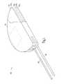
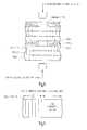
- FIG. 7shows a top view of a cathode and anode layer separated by separator (for example, kraft paper).
- the cathode layerincludes one or more holes which provide ample clearance for a conductive interconnect.
- the x-section of FIG. 7, shown in FIG. 8,shows that the conductive interconnect will interconnect anode layers without contacting an intervening cathode layer.
- the cross section of the cathode holeexceeds that of the conductive interconnect to avoid shorting the cathode to the anodes.
- the conductive interconnectis electrically connected to the anodes by welding, such as ultrasonic, resistance or other types of welding.
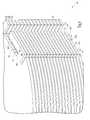
- One way to facilitate connectionsis to use a masking process for connection surfaces on the foil to ensure that the masked surfaces are not etched and/or formed.
- One way to avoid mechanical breakage of the foilsis to use a masking technique which provides gradually non-etched portions of the foil to avoid mechanical stresses (e.g. high stress points) due to discontinuites of etching and which provides a suitable region for interconnection of the via to the foil. This is demonstrated by FIG. 9 .
- the vertical linesshow the cross-section of unmasked and masked foil portions. The figure shows that foil etching gradually diminishes over the transition from masked portion to unmasked portion. It is noted that the example shows a pure aluminum foil, but that other etchings and foils may be masked without departing from the scope of the present system.
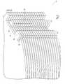
- FIG. 10shows a side view of a foil and positions of the masks for one embodiment of the present system.
- the top viewis provided in FIG. 11 .
- the positions, shapes and sizes of the masksmay vary without departing from the present system, and the demonstrated masks are shown to illustrate the system and are not intended in an exhaustive or exclusive sense.
- thickness tis 100 micrometers. However, it is contemplated that other thicknesses may be used without departing from the present system. For example, other thicknesses, including, but not limited to, 50-600 micrometers may be used.
- the foil dimensionsare shown as 500 ⁇ 250 millimeters, but other sized foils may be employed without departing from the scope of the present system.
- a master roll of foilis masked to provide d-shaped cutouts with accurately placed masks where the conductive interconnects are to contact the foil.
- the spacing between foilsmust be large enough to provide a “web” for processing the cutouts.
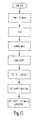
- FIG. 12shows one process for providing one embodiment of a capacitor according to some of the teachings herein.
- Raw foilis masked by printing the mask on the foil.
- the masked foilis etched and then the mask is removed.
- Oxidesare formed on the foil and it is then cut into subrolls.
- the subrollsare processed by cutting shapes for the final capacitor out of the subrolls.
- the foil shapesare used to make the capacitors.
- the cathode foilsare processed to accurately place the cathode holes, which correspond to anode mask layers when overlapped. Paper separators are also cut to provide space for the conductive interconnects. In one application, the perimeter of the paper is smaller than that of the cathode to provide a nonconductive guide for the conductive interconnect. In alternate embodiments, an insulator may be used to position the conductive interconnect and to insulate against cathode contact.
- the conductive interconnectsmay be connected to formed or unformed portions of the anode layer.
- One way to manufacture a capacitor according to the present teachingsis to use a robotic assembly method, whereby anodes which are already masked, etched, and formed are stacked, followed by separator material, and then cathode material.
- the cathodesare precision punched to provide accurately placed cathode holes.
- the robotcan use the cathode features to accurately place the cathode relative to the anodes.
- a separator layer and an anode layerare also placed over the cathode using the robot.
- the conductive interconnectis a metal plug
- the robotplaces the conductive plug accurately prior to the placement of the separator and anode layers. This process may be repeated to provide a stack of anodes of multiple layers interspersed with separator and cathode layers.
- the robotcan also be used to perform the welding steps.
- the conductive interconnectsmay be made of a non-circular cross section.
- the conductive interconnectsmay be made of a suitable metal, such as aluminum.
- the conductive interconnectsmay also be made of other materials, including, but not limited to, conductive epoxy, conductive polymer (such as polyimide filled with aluminum), or fused aluminum powder.
- the metal used in the conductive interconnectshould match the anode metal.
- Other anode metals/interconnect metal pairsmay be used including, but not limited to, tantalum, hafnium, niobium, titanium, zirconium, or combinations of these metals.
- connectionmay be performed using the teachings provided herein.
- use of the present systemis not limited to anode-anode connections.
- the anode layersconsist of a plurality of anode foils.
- a single anode foilis interconnected to a triple anode foil or any multiplicity of anode foil combinations.
- an anode layermay include a plurality of parts and/or layers.
- the anode layermay include two different anode shapes in the same layer to provide a contoured edge. The shapes may be electrically connected to provide an equipotential surface.
- the use of multiple anode parts for a single layerfacilitates the construction of a capacitor of virtually any form factor.
- anode-cathode-anode stacksat different points for different conductive interconnects in one operation.
- several anode/cathode layerscan be welded in a single operation.
- the electrical connection systemprovides mechanical stability; and alignment to the stack as the layers are being assembled; taping is not required; the assembly is ready for insertion into the capacitor case; surface area is optimized; interior alignment is facilitated using interior features to align the stack layer to layer; edge-welding and/or intra-anode staking may be eliminated; and, in some embodiments, paper gluing may be eliminated.
- FIG. 13shows one of the many applications for capacitors incorporating one or more teachings of the present invention: an implantable heart monitor or apparatus 700 .
- implantable heart monitorincludes any implantable device for providing therapeutic stimulus to a heart muscle.
- the termincludes pacemakers, defibrillators, cardioverters, congestive heart failure devices, and combinations and permutations thereof.
- Heart monitor 700includes a lead system 703 , which after implantation electrically contact strategic portions of a patient's heart. Shown schematically are portions of monitor 700 including a monitoring circuit 702 for monitoring heart activity through one or more of the leads of lead system 703 , and a therapy circuit 701 for delivering electrical energy through one or more of the leads to a heart. Monitor 700 also includes an energy storage component, which includes a battery 704 and incorporates at least one capacitor 705 having one or more of the features of the exemplary capacitors described above.
- teachings of the present inventioncan be incorporated into cylindrical capacitors and/or capacitors used for photographic flash equipment. Indeed, teachings of the invention are pertinent to any application where high-energy, high-voltage, or space-efficient capacitors are desirable. Moreover, one or more teachings are applicable to batteries.
- a methodincludes connecting together one or more anode connection members of one or more anode foils and one or more cathode connection members of one or more cathode foils and electrically isolating the one or more anode foils from the one or more cathode foils.
- the exemplary methodreduces the number of processing steps for constructing a capacitor.
Landscapes
- Health & Medical Sciences (AREA)
- Engineering & Computer Science (AREA)
- Cardiology (AREA)
- Power Engineering (AREA)
- Animal Behavior & Ethology (AREA)
- Veterinary Medicine (AREA)
- Biomedical Technology (AREA)
- Nuclear Medicine, Radiotherapy & Molecular Imaging (AREA)
- Radiology & Medical Imaging (AREA)
- Life Sciences & Earth Sciences (AREA)
- Microelectronics & Electronic Packaging (AREA)
- General Health & Medical Sciences (AREA)
- Public Health (AREA)
- Heart & Thoracic Surgery (AREA)
- Electrotherapy Devices (AREA)
- Fixed Capacitors And Capacitor Manufacturing Machines (AREA)
- Semiconductor Integrated Circuits (AREA)
- Internal Circuitry In Semiconductor Integrated Circuit Devices (AREA)
- Microwave Amplifiers (AREA)
- Microwave Tubes (AREA)
- Die Bonding (AREA)
- Emergency Protection Circuit Devices (AREA)
- Ceramic Capacitors (AREA)
Abstract
Description
This application is related to application Ser. No. 09/706,447, filed on even date herewith, entitled FLAT CAPACITOR FOR AN IMPLANTABLE MEDICAL DEVICE, which is incorporated herein by reference in its entirety.
The present invention concerns implantable medical devices, such as defibrillators and cardioverters, particularly structures and methods for capacitors in such devices.
Capacitors have undergone substantial improvement over the years. Smaller capacitors are in demand for various applications. One such application is for biomedical implants. For example, defibrillators and pacemakers use capacitors for pulse delivery.
The defibrillator or cardioverter includes a set of electrical leads, which extend from a sealed housing into the walls of a heart after implantation. Within the housing are a battery for supplying power, monitoring circuitry for detecting abnormal heart rhythms, and a capacitor for delivering bursts of electric current through the leads to the heart.
The capacitor can take the form of a flat aluminum electrolytic capacitor. Flat capacitors include a stack of flat capacitor elements mounted within a capacitor case. Each flat capacitor element includes one or more separators between two, sheets of aluminum foil. One of the aluminum foils serves as a cathode (negative) foil, and the other serves as an anode (positive) foil. The capacitor elements each have an individual capacitance (or energy-storage capacity) proportional to the surface area of the foil.
One drawback in manufacturing such capacitors is that each of the anodes and each of the cathodes must be connected together. For instance, all the anodes are crimped or welded together and attached to a feedthrough terminal for connection to circuitry outside the capacitor case. Another process is also done for the cathode foils in the capacitor stack. Errors during the manufacturing steps may cause defects in the capacitor or decrease the reliability of the capacitor after it is constructed. Another drawback is that the interconnections take up space within the capacitor. This increases the size of the capacitor, which is undesirable when the capacitors are used for implantable medical devices such as defibrillators.
Thus, what is needed is a simple way to provide the anode and cathode interconnections of capacitors with as few steps as possible and which lends itself to mass producing said capacitors.
To address these and other needs, interconnection structures and methods for flat capacitors have been devised. In one embodiment, a method includes connecting together one or more anode connection members of one or more anode foils and one or more cathode connection members of one or more cathode foils and electrically isolating the one or more anode foils from the one or more cathode foils. Among other advantages, the method reduces the processing steps for interconnecting the foils of a capacitor, and provides a capacitor having a smaller amount of room taken up by its interconnections.
In one aspect, a capacitor having a first anode layer, a second anode layer, a cathode layer between the first anode layer and the second anode layer, a first separator layer between the first anode layer and the cathode layer, a second separator layer between the second anode layer and the cathode layer; and a conductive interconnect between the first anode layer and the second anode layer, the conductive interconnect passing through a cathode hole in the cathode; wherein the conductive interconnect has a cross section which is smaller than the cathode hole and the conductive interconnect is placed to avoid direct electrical contact with the cathode layer and wherein the first anode and the second anode are electrically connected through the conductive interconnect.
Another aspect of the present invention includes various implantable medical devices, such as pacemakers, defibrillators, and cardioverters, incorporating one or more capacitors having one or more of the novel features described above.
FIG. 1 is an isometric view of a flat capacitor according to one embodiment of the present invention.
FIG. 2A is a top view of an anode foil for use in constructing a capacitor according to one embodiment of the present invention.
FIG. 2B is a top view of a cathode foil for use in constructing a capacitor according to one embodiment of the present invention.
FIG. 3A is a top view of an anode foil for use in constructing a capacitor according to one embodiment of the present invention.
FIG. 3B is a top view of a cathode foil for use in constructing a capacitor according to one embodiment of the present invention.
FIG. 4 is a perspective view of a stack of one or more anodes and cathodes of FIGS. 2A and 2B.
FIG. 5 is a perspective view of the stack of FIG. 4 after the stack has been processed according to one embodiment of the present invention.
FIG. 6 is a flowchart depicting a method of interconnecting anodes and cathode foils of a capacitor according to one embodiment of the present invention.
FIG. 7 shows a top view of a capacitor stack according to one embodiment.
FIG. 8 shows a cross-section of a portion of FIG.7.
FIG. 9 shows a partially etched anode foil according to one embodiment.
FIG. 10 shows a side view of a foil having masks according to one embodiment.
FIG. 11 show a top view of FIG.10.
FIG. 12 shows a method according to one embodiment.
FIG. 13 is a block diagram of a generic implantable medical device including a capacitor according to one embodiment of the present invention.
The following detailed description, which references and incorporates the figures, describes and illustrates one or more specific embodiments of the invention. These embodiments, offered not to limit but only to exemplify and teach the invention, are shown and described in sufficient detail to enable those skilled in the art to practice the invention. Thus, where appropriate to avoid obscuring the invention, the description may omit certain information known to those of skill in the art.
FIG. 1 shows aflat capacitor 100 constructed according to one embodiment of the present invention. Althoughcapacitor 100 is a D-shaped capacitor, in other embodiments, the capacitor is another desirable shape, including, but not limited to rectangular, circular, oval or other symmetrical or asymmetrical shape. Capacitor100 includes acase 101 which contains acapacitor stack 102. In the exemplary embodiment,case 101 is manufactured from a conductive material, such as aluminum. In other embodiments, the case is manufactured using a nonconductive material, such as a ceramic or a plastic.
Capacitor100 includes afirst terminal 103 and asecond terminal 104 for connectingcapacitor stack 102 to an outside electrical component, such as heart monitor circuitry, including defibrillator, cardioverter, and pacemaker circuitry. In the exemplary embodiment,terminal 103 is a feedthrough terminal insulated fromcase 101, whileterminal 104 is directly connected tocase 101. In other embodiments, the capacitor incorporates other connection methods, depending on other design factors. For instance, in some embodiments,capacitor 100 includes two ormore feedthrough terminals 103.
The separator is located between each anode and cathode. In one embodiment, the separator includes one or more sheets of kraft paper impregnated with an electrolyte. In one embodiment, the separator includes two sheets of paper. The electrolyte can be any suitable electrolyte for an electrolytic capacitor, such as an ethylene-glycol base combined with polyphosphates, ammonium pentaborate, and/or an adipic acid solute.
In one embodiment, one or more of the anodes ofcapacitor stack 102 is a multi-anode stack which includes three foil layers. In other embodiments, one or more anode stacks include one, two, three or more anode foils having a variety of anode shapes. The anode foils are generally foil structures and can include aluminum, tantalum, hafnium, niobium, titanium, zirconium, and combinations of these metals. In one embodiment, at least portions of a major surface of each anode foil is roughened or etched to increase its effective surface area. This increases the capacitive effect of the foil with no relative increase in volume. Other embodiments incorporate other foil compositions and/or classes of foil compositions.
In one embodiment, each anode is connected to the other anodes of the capacitor and coupled tofeedthrough assembly 103 for electrically connecting the anode to circuitry outside the case. In some embodiments, the anodes are connected to the case and the cathodes are coupled to a feedthrough assembly. In other embodiments, both the anode and the cathode are connected to feedthroughs.
FIG. 2A shows ananode 202 according to one embodiment of the present invention.Anode 202 is shown before it is assembled intocapacitor stack 102 as shown in FIG.1.Anode 202 includes amain body portion 204 having one ormore connection members 206. In one embodiment,connection member 206 includes one or more separate members attached to the anode by welding, staking, or other connection method.
In other embodiments,connection member 206 is an integral portion ofanode 202, and is punched, laser-cut, or otherwise shaped from the anode foil. In such an embodiment, portions ofconnection member 206 are not etched along with the rest ofanode 202. For instance, a chemical mask is put on portions ofconnection member 206 to keep those masked portions from becoming etched during the etching process. As will be discussed below, this provides that those unetched, non-porous sections make welding the edges of the anodes to each other easier.
In one embodiment,proximal section 208 is connected tomain body 204 and is defined in part by a pair of cut-outportions proximal section 208.Distal section 210 is connected to a portion ofproximal section 208. In one embodiment, it is integral withproximal section 208. In some embodiments,distal section 210 is attached as a separate member. In one embodiment,distal section 210 is defined in part by a cut-outportion 216 which is located betweenmain body 204 anddistal section 210, and a cut-outportion 218 which separatesdistal section 210 frommain body 204.
In this embodiment,connection member 206 is located within the general. perimeter or outline ofanode 202. In other embodiments, connection member extends further from the main body ofanode 202 orconnection member 206 is more internal within the main body ofanode 202.
In some embodiments, each anode foil incapacitor stack 102 includes an, connection member such asconnection member 206. In other embodiments, one or more anode foils in a multi-anode stack have aconnection member 206 while the other anode foils in the multi-anode stack are connected to the anode having the connection member. For instance, in one embodiment, a three-foil anode stack includes one foil having anconnection member 206 and two foils without connection members. The two foils without connection members are welded, staked, or otherwise attached to the foil having the connection member.
FIG. 2B shows acathode 302 according to one embodiment of the present invention.Cathode 302 is shown before it is assembled intocapacitor stack 102 as shown in FIG.1.Cathode 302 includes amain body portion 304 having one ormore connection members 306. In one embodiment,connection member 306 is an integral portion ofcathode 302, and is punched, laser-cut, or otherwise shaped from the anode foil. In one embodiment,connection member 306 includes one or more separate members attached to the anode by welding, staking, or other connection method.
In one embodiment,connection member 306 includes aproximal section 308 and adistal section 310. In the embodiment of FIG. 2B,connection member 306 is an L-shaped member. However, in some embodiments it is hook shaped, U-shaped, and/or have other shape.
In one embodiment,proximal section 308 is connected tomain body 304 and is defined in part by a pair of cut-outportions proximal section 308.Distal section 310 is connected to a portion ofproximal section 308. In one embodiment, it is integral withproximal section 308. In some embodiments,distal section 310 is attached as a separate member. In one embodiment,distal section 310 is defined in part by a cut-outportion 316 which is located betweenmain body 304 anddistal section 310, and a cut-outportion 318 which separatesdistal section 310 frommain body 304.
In this embodiment,connection member 306 is located within the general perimeter or outline ofcathode 302. In other embodiments,connection member 306 extends further from the main body ofcathode 302 orconnection member 306 is more internal within the main body ofcathode 302.
FIGS. 3A and 3B show ananode 202′ and acathode 302′ according to one embodiment of the present invention.Anode 202′ andcathode 302′ are shown before it is assembled intocapacitor stack 102 as shown in FIG.1.Anode 202′ andcathode 302′ are generally similar toanode 202 andcathode 302, respectively, exceptconnection member 206′ does not include a cut-out such as cut-out212 ofanode 202 andconnection member 306′ does not include a cut-out such as cut-out318 ofcathode 302. Other embodiments utilize other shapes and locations for connection members such asconnection members
For instance, in various embodiments,connection members embodiments connection members edges respective foils curved edges respective foils main bodies
In one embodiment,proximal section 308 ofcathode 302 andproximal section 208 ofanode 202 are located in different positions (relative to each other) on their respective foils, whiledistal sections embodiment connection members anode 202 and thecathode 302, respectively, are mirror images of each other. In some embodiments,connection members
FIG. 4 shows astack 402 of one or more alternatinganodes 202 andcathodes 302. As shown in FIG. 4,connection members connection members
For instance,proximal sections 208 ofanodes 202 are exclusively positioned or located. This means that at least a portion ofproximal sections 208 do not overlay or underlay a portion of cathodes203. Likewise,proximal sections 308 ofcathodes 302 are exclusive portions and include at least a portion not overlaying or underlaying a portion ofanode 202. Conversely,distal sections portions
When stacked as shown in FIG. 4, the edges ofdistal sections surface 410. In this embodiment,surface 410 can generally be described as having afirst portion 410awhich fronts theproximal sections 208 ofanodes 202, asecond portion 410bwhich fronts common cut-portions third portion 410cwhich fronts theproximal sections 308 ofcathodes 302.
In this embodiment,distal sections anode connection member 206 andcathode connection member 306 are fully overlaying one another. Fully overlaying means that there are generally no gaps alongsurface 410 ofstack 402 when the anodes and cathodes are stacked as in FIG.4. The fully overlayed structure ofstack 402 provides acomplete surface 410 which provides for ease of edge-welding or otherwise connectingconnection members surface 410 when the anodes and cathodes are stacked. For instance, in some embodiments, one or more ofdistal sections front surface 410.
After being stacked as discussed above, at least portions ofconnection members distal sections distal sections surface 410. In one embodiment,distal sections portion surface 410. In one embodiment,distal sections surface 410. In some embodiments, portions ofdistal sections proximal sections 208 are connected to each other and/or portions ofproximal sections 308 are connected to each other.
After being connected, portions ofconnection members proximal sections sections capacitor 100.
FIG. 5 shows stack402 after portions ofdistal sections separation 502 betweenanode connection members 206, which together compriseanode connection section 508, andcathode connection members 306, which together comprisecathode connection section 510.Separation 502 in the present embodiment electrically isolatessection 508 fromsection 510.Proximal sections 308 are still coupled to each other as areproximal sections 208. In some embodiments,separation 502 is a thin slice. In some embodiments,separation 502 is as wide as cut-outs separation 502. In various embodiments,separation 502 is formed by laser cutting, punching, and/or tool or machine cutting.
FIG. 6 shows a flowchart depicting amethod 600 for interconnecting two or more foils of a capacitor according to one embodiment of the present invention.Method 600 includes ablock 602, positioning the connection members of two or more foils, ablock 604, connecting the connection members, and block606, electrically isolating portions of the connection members from each other.
In one embodiment, block602, positioning the connection members of two or more foils, includes stacking an anode foil having a connection member having a proximal section and a distal section upon a cathode foil having a connection member having a proximal section and a distal section. The foils and connection members are positioned so that the proximal section of the anode foil connection member does not overlay the proximal section of the cathode foil connection member and the distal section of the anode foil connection member at least partially overlays the distal section of the cathode foil connection member.
In one embodiment, block604, connecting the connection members, includes connecting the connection member of the anode foil to the connection member of the cathode foil. In one embodiment, this includes connecting the distal section of the anode connection member and the distal section of the cathode connection member at a portion of the anode connection member that overlays (or underlays) the portion of the cathode connection member. In one embodiment, connecting comprises a single, continuous connection process. For instance, a laser weld or staking process is performed which attaches all the anode and cathode foil connection members together during a single, uninterrupted process. In one embodiment, the connection is performed by edge-welding at least a portion of the distal sections of the anode foil and the cathode foil together. One embodiment includes a laser edge-welding process.
Alternatively, in some embodiments, a portion of the stack is welded during a different process or by a different method than the first process. Some embodiments include soldering, staking, swaging, and/or applying an electrically conductive adhesive.
In one embodiment,connection members
In one embodiment, block606, electrically isolating portions of the connection members from each other, includes removing portions of the anode connection member and the cathode connection member. In one embodiment, the removed portion includes where the cathode connection member overlays (or underlays) a portion of the anode connection member. In one embodiment, this includes removing a portion of the distal sections of the anode connection member and the cathode connection member. In one embodiment, electrically isolating comprises punching-out a portion of the distal section of the anode foil connection member and the distal section of the cathode foil connection member. In one embodiment, electrically isolating includes laser cutting a portion of the distal section of the anode connection member and the distal section of the cathode connection member.
After being processed as discussed above inblock 606,proximal sections 208 of the connection members ofanodes 202 are still coupled together andproximal sections 308 of the connection members ofcathodes 302 are still coupled to each other, while theanodes 202 andcathodes 302 are electrically isolated from each other. Feedthroughs or other terminal members are then used to couple the anodes and cathodes to outside circuitry.
One aspect of the present capacitor includes a system for interconnecting anode layers in a flat capacitor stack using vias. In one embodiment, vias are employed to interconnect anode layers. In one embodiment, the vias are made by inserting conductive interconnects which interconnect anode layers without contacting an intervening cathode layer.
For example, FIG. 7 shows a top view of a cathode and anode layer separated by separator (for example, kraft paper). The cathode layer includes one or more holes which provide ample clearance for a conductive interconnect. The x-section of FIG. 7, shown in FIG. 8, shows that the conductive interconnect will interconnect anode layers without contacting an intervening cathode layer. Thus, the cross section of the cathode hole exceeds that of the conductive interconnect to avoid shorting the cathode to the anodes. The conductive interconnect is electrically connected to the anodes by welding, such as ultrasonic, resistance or other types of welding.
One way to facilitate connections is to use a masking process for connection surfaces on the foil to ensure that the masked surfaces are not etched and/or formed. One way to avoid mechanical breakage of the foils is to use a masking technique which provides gradually non-etched portions of the foil to avoid mechanical stresses (e.g. high stress points) due to discontinuites of etching and which provides a suitable region for interconnection of the via to the foil. This is demonstrated by FIG.9. The vertical lines show the cross-section of unmasked and masked foil portions. The figure shows that foil etching gradually diminishes over the transition from masked portion to unmasked portion. It is noted that the example shows a pure aluminum foil, but that other etchings and foils may be masked without departing from the scope of the present system.
FIG. 10 shows a side view of a foil and positions of the masks for one embodiment of the present system. The top view is provided in FIG.11. The positions, shapes and sizes of the masks may vary without departing from the present system, and the demonstrated masks are shown to illustrate the system and are not intended in an exhaustive or exclusive sense. In one embodiment, thickness t is 100 micrometers. However, it is contemplated that other thicknesses may be used without departing from the present system. For example, other thicknesses, including, but not limited to, 50-600 micrometers may be used.
The foil dimensions are shown as 500×250 millimeters, but other sized foils may be employed without departing from the scope of the present system. In one application of the present system, a master roll of foil is masked to provide d-shaped cutouts with accurately placed masks where the conductive interconnects are to contact the foil. In one application, the spacing between foils must be large enough to provide a “web” for processing the cutouts.
FIG. 12 shows one process for providing one embodiment of a capacitor according to some of the teachings herein. Raw foil is masked by printing the mask on the foil. The masked foil is etched and then the mask is removed. Oxides are formed on the foil and it is then cut into subrolls. The subrolls are processed by cutting shapes for the final capacitor out of the subrolls. The foil shapes are used to make the capacitors.
The cathode foils are processed to accurately place the cathode holes, which correspond to anode mask layers when overlapped. Paper separators are also cut to provide space for the conductive interconnects. In one application, the perimeter of the paper is smaller than that of the cathode to provide a nonconductive guide for the conductive interconnect. In alternate embodiments, an insulator may be used to position the conductive interconnect and to insulate against cathode contact.
It is noted that the conductive interconnects may be connected to formed or unformed portions of the anode layer.
One way to manufacture a capacitor according to the present teachings is to use a robotic assembly method, whereby anodes which are already masked, etched, and formed are stacked, followed by separator material, and then cathode material. In one assembly process, the cathodes are precision punched to provide accurately placed cathode holes. The robot can use the cathode features to accurately place the cathode relative to the anodes. A separator layer and an anode layer are also placed over the cathode using the robot. In embodiments where the conductive interconnect is a metal plug, the robot places the conductive plug accurately prior to the placement of the separator and anode layers. This process may be repeated to provide a stack of anodes of multiple layers interspersed with separator and cathode layers. The robot can also be used to perform the welding steps.
Other types of conductive interconnects may be used without departing from the present system. For example, the conductive interconnects may be made of a non-circular cross section. The conductive interconnects may be made of a suitable metal, such as aluminum. The conductive interconnects may also be made of other materials, including, but not limited to, conductive epoxy, conductive polymer (such as polyimide filled with aluminum), or fused aluminum powder. The metal used in the conductive interconnect should match the anode metal. Other anode metals/interconnect metal pairs may be used including, but not limited to, tantalum, hafnium, niobium, titanium, zirconium, or combinations of these metals.
It is understood that other connections may be performed using the teachings provided herein. For example, it is possible to create a series of interconnections between cathode layers using the teachings provided. Thus, use of the present system is not limited to anode-anode connections.
In one embodiment, the anode layers consist of a plurality of anode foils. In one application is it is possible that a single anode foil is interconnected to a triple anode foil or any multiplicity of anode foil combinations.
In one embodiment an anode layer may include a plurality of parts and/or layers. For example, the anode layer may include two different anode shapes in the same layer to provide a contoured edge. The shapes may be electrically connected to provide an equipotential surface. The use of multiple anode parts for a single layer facilitates the construction of a capacitor of virtually any form factor.
Furthermore, it is possible to weld multiple anode-cathode-anode stacks at different points for different conductive interconnects in one operation. Additionally, depending on the welding process used, several anode/cathode layers can be welded in a single operation.
Some of the benefits of the present system include, but are not limited to, the following: the electrical connection system provides mechanical stability; and alignment to the stack as the layers are being assembled; taping is not required; the assembly is ready for insertion into the capacitor case; surface area is optimized; interior alignment is facilitated using interior features to align the stack layer to layer; edge-welding and/or intra-anode staking may be eliminated; and, in some embodiments, paper gluing may be eliminated.
FIG. 13 shows one of the many applications for capacitors incorporating one or more teachings of the present invention: an implantable heart monitor orapparatus 700. As used herein, implantable heart monitor includes any implantable device for providing therapeutic stimulus to a heart muscle. Thus, for example, the term includes pacemakers, defibrillators, cardioverters, congestive heart failure devices, and combinations and permutations thereof.
In addition to implantable heart monitor and other cardiac rhythm management devices, one or more teachings of the present invention can be incorporated into cylindrical capacitors and/or capacitors used for photographic flash equipment. Indeed, teachings of the invention are pertinent to any application where high-energy, high-voltage, or space-efficient capacitors are desirable. Moreover, one or more teachings are applicable to batteries.
In furtherance of the art, the inventors have devised connection structures and methods for interconnecting the anode foils and the cathode foils of capacitors. In one embodiment, a method includes connecting together one or more anode connection members of one or more anode foils and one or more cathode connection members of one or more cathode foils and electrically isolating the one or more anode foils from the one or more cathode foils. Among other advantages, the exemplary method reduces the number of processing steps for constructing a capacitor.
It is understood that the above description is intended to be illustrative, and not restrictive. Many other embodiments will be apparent to those of skill in the art upon reviewing the above description. The scope of the invention should, therefore, be determined with reference to the appended claims, along with the full scope of equivalents to which such claims are entitled.
Claims (16)
1. A capacitor, comprising:
a first anode layer;
a second anode layer;
a cathode layer between the first anode layer and the second anode layer;
a first separator layer between the first anode layer and the cathode layer;
a second separator layer between the second anode layer and the cathode layer; and
a conductive interconnect between the first anode layer and the second anode layer, the conductive interconnect passing through a cathode hole in the cathode;
wherein the conductive interconnect has a cross section which is smaller than the cathode hole and the conductive interconnect is placed to avoid direct electrical contact with the cathode layer and wherein the first anode and the second anode are electrically connected through the conductive interconnect.
2. The capacitor ofclaim 1 , wherein the first anode layer is substantially flat.
3. The capacitor ofclaim 1 , wherein the conductive interconnect is aluminum.
4. The capacitor ofclaim 1 , wherein the cross section is circular.
5. The capacitor ofclaim 1 , wherein the cross section is noncircular.
6. The capacitor ofclaim 1 , wherein the conduction interconnect is ultrasonically welded to the first anode layer and the second anode layer.
7. The capacitor ofclaim 1 , wherein the conduction interconnect is resistance welded to the first anode layer and the second anode layer.
8. The capacitor ofclaim 1 , wherein the conductive interconnect mates to an unetched region of the first anode layer.
9. The capacitor ofclaim 1 , wherein the conductive interconnect mates to an unformed region of the first anode layer.
10. The capacitor ofclaim 1 , wherein the conductive interconnect includes a rivet.
11. The capacitor ofclaim 1 , wherein the conductive interconnect includes a wire.
12. The capacitor ofclaim 1 , wherein the conductive interconnect includes a conductive epoxy.
13. The capacitor ofclaim 1 , wherein the conductive interconnect includes a conductive polymer.
14. The capacitor ofclaim 1 , wherein the conductive interconnect includes a polyimide filled with aluminum.
15. The capacitor ofclaim 1 , wherein the conductive interconnect includes a fused aluminum powder.
16. The capacitor ofclaim 1 , wherein the conductive interconnect includes a conductive staple.
Priority Applications (14)
| Application Number | Priority Date | Filing Date | Title |
|---|---|---|---|
| US09/706,519US6509588B1 (en) | 2000-11-03 | 2000-11-03 | Method for interconnecting anodes and cathodes in a flat capacitor |
| AT01993009TATE364889T1 (en) | 2000-11-03 | 2001-10-31 | METHOD FOR CONNECTING ANODES AND CATHODES IN A FLAT CAPACITOR |
| EP06021404AEP1744333B1 (en) | 2000-11-03 | 2001-10-31 | Method for interconnecting anodes and cathodes in a flat capacitor |
| EP01993009AEP1352405B1 (en) | 2000-11-03 | 2001-10-31 | Method for interconnecting anodes and cathodes in a flat capacitor |
| AT06021404TATE425545T1 (en) | 2000-11-03 | 2001-10-31 | METHOD FOR CONNECTING ANODES AND CATHODES IN A FLAT CAPACITOR |
| DE60137981TDE60137981D1 (en) | 2000-11-03 | 2001-10-31 | Method for connecting anodes and cathodes in a flat capacitor |
| AU2002220013AAU2002220013A1 (en) | 2000-11-03 | 2001-10-31 | Method for interconnecting anodes and cathodes in a flat capacitor |
| DE60128958TDE60128958T2 (en) | 2000-11-03 | 2001-10-31 | METHOD FOR CONNECTING ANODES AND CATHODES IN A FLAT CONDENSER |
| PCT/US2001/045202WO2002037515A2 (en) | 2000-11-03 | 2001-10-31 | Method for interconnecting anodes and cathodes in a flat capacitor |
| US10/299,234US6709946B2 (en) | 2000-11-03 | 2002-11-19 | Method for interconnecting anodes and cathodes in a flat capacitor |
| US10/804,288US6999304B2 (en) | 2000-11-03 | 2004-03-18 | Foil structures for use in a capacitor with an anode foil and a cathode foil stacked together |
| US10/874,798US7456077B2 (en) | 2000-11-03 | 2004-06-23 | Method for interconnecting anodes and cathodes in a flat capacitor |
| US11/325,931US7221556B2 (en) | 2000-11-03 | 2006-01-05 | Implantable medical device with a capacitor that includes stacked anode and cathode foils |
| US12/268,751US8451587B2 (en) | 2000-11-03 | 2008-11-11 | Method for interconnecting anodes and cathodes in a flat capacitor |
Applications Claiming Priority (1)
| Application Number | Priority Date | Filing Date | Title |
|---|---|---|---|
| US09/706,519US6509588B1 (en) | 2000-11-03 | 2000-11-03 | Method for interconnecting anodes and cathodes in a flat capacitor |
Related Child Applications (1)
| Application Number | Title | Priority Date | Filing Date |
|---|---|---|---|
| US10/299,234DivisionUS6709946B2 (en) | 2000-11-03 | 2002-11-19 | Method for interconnecting anodes and cathodes in a flat capacitor |
Publications (1)
| Publication Number | Publication Date |
|---|---|
| US6509588B1true US6509588B1 (en) | 2003-01-21 |
Family
ID=24837963
Family Applications (5)
| Application Number | Title | Priority Date | Filing Date |
|---|---|---|---|
| US09/706,519Expired - LifetimeUS6509588B1 (en) | 2000-11-03 | 2000-11-03 | Method for interconnecting anodes and cathodes in a flat capacitor |
| US10/299,234Expired - Fee RelatedUS6709946B2 (en) | 2000-11-03 | 2002-11-19 | Method for interconnecting anodes and cathodes in a flat capacitor |
| US10/804,288Expired - LifetimeUS6999304B2 (en) | 2000-11-03 | 2004-03-18 | Foil structures for use in a capacitor with an anode foil and a cathode foil stacked together |
| US11/325,931Expired - Fee RelatedUS7221556B2 (en) | 2000-11-03 | 2006-01-05 | Implantable medical device with a capacitor that includes stacked anode and cathode foils |
| US12/268,751Expired - Fee RelatedUS8451587B2 (en) | 2000-11-03 | 2008-11-11 | Method for interconnecting anodes and cathodes in a flat capacitor |
Family Applications After (4)
| Application Number | Title | Priority Date | Filing Date |
|---|---|---|---|
| US10/299,234Expired - Fee RelatedUS6709946B2 (en) | 2000-11-03 | 2002-11-19 | Method for interconnecting anodes and cathodes in a flat capacitor |
| US10/804,288Expired - LifetimeUS6999304B2 (en) | 2000-11-03 | 2004-03-18 | Foil structures for use in a capacitor with an anode foil and a cathode foil stacked together |
| US11/325,931Expired - Fee RelatedUS7221556B2 (en) | 2000-11-03 | 2006-01-05 | Implantable medical device with a capacitor that includes stacked anode and cathode foils |
| US12/268,751Expired - Fee RelatedUS8451587B2 (en) | 2000-11-03 | 2008-11-11 | Method for interconnecting anodes and cathodes in a flat capacitor |
Country Status (6)
| Country | Link |
|---|---|
| US (5) | US6509588B1 (en) |
| EP (2) | EP1352405B1 (en) |
| AT (2) | ATE425545T1 (en) |
| AU (1) | AU2002220013A1 (en) |
| DE (2) | DE60137981D1 (en) |
| WO (1) | WO2002037515A2 (en) |
Cited By (47)
| Publication number | Priority date | Publication date | Assignee | Title |
|---|---|---|---|---|
| US20020151936A1 (en)* | 2001-03-02 | 2002-10-17 | Michael Kloss | Therapy optimization in heart failure patients based on minute ventilation patterns |
| US6632720B2 (en)* | 2002-01-15 | 2003-10-14 | Cardiac Pacemakers, Inc. | Method of constructing a capacitor stack for a flat capacitor |
| US20040019268A1 (en)* | 2000-11-03 | 2004-01-29 | Cardiac Pacemakers, Inc. | Configurations and methods for making capacitor connections |
| US6706059B2 (en) | 1999-12-01 | 2004-03-16 | Cardiac Pacemakers, Inc. | Reforming wet-tantalum capacitors in implantable medical devices |
| US20040098058A1 (en)* | 1999-12-01 | 2004-05-20 | Cardiac Pacemakers, Inc. | Reforming wet-tantalum capacitors in implantable defibrillators and other medical devices |
| US20040095199A1 (en)* | 2002-11-13 | 2004-05-20 | Kozo Ono | Surface mount crystal unit and surface mount crystal oscillator |
| US20040114311A1 (en)* | 2000-11-03 | 2004-06-17 | Cardiac Pacemakers, Inc. | Flat capacitor having staked foils and edge-connected connection members |
| US20040127952A1 (en)* | 2002-12-31 | 2004-07-01 | O'phelan Michael J. | Batteries including a flat plate design |
| US20040130851A1 (en)* | 2002-10-25 | 2004-07-08 | Faris Sadeg M. | Fluid deionization system |
| US6763265B2 (en) | 2000-11-03 | 2004-07-13 | Cardiac Pacemakers, Inc. | Method of constructing a capacitor stack for a flat capacitor |
| US20040147960A1 (en)* | 2000-11-03 | 2004-07-29 | Cardiac Pacemakers, Inc. | Flat capacitor for an implantable medical device |
| US20040173835A1 (en)* | 2000-11-03 | 2004-09-09 | Cardiac Pacemakers, Inc. | Method for interconnecting anodes and cathodes in a flat capacitor |
| US20040174658A1 (en)* | 2000-11-03 | 2004-09-09 | Cardiac Pacemakers, Inc. | Implantable heart monitors having flat capacitors with curved profiles |
| US20040193221A1 (en)* | 2000-11-03 | 2004-09-30 | Cardiac Pacemakers, Inc. | Implantable heart monitors having capacitors with endcap headers |
| US20040215281A1 (en)* | 2000-11-03 | 2004-10-28 | Cardiac Pacemakers, Inc. | Capacitor having a feedthrough assembly with a coupling member |
| US6819544B1 (en)* | 2003-05-30 | 2004-11-16 | Medtronic, Inc. | Dual-anode electrolytic capacitor for use in an implantable medical device |
| US20040230240A1 (en)* | 2000-09-08 | 2004-11-18 | Cardiac Pacemakers, Inc. | Self-calibrating rate-adaptive pacemaker |
| US6833987B1 (en) | 2000-11-03 | 2004-12-21 | Cardiac Pacemakers, Inc. | Flat capacitor having an active case |
| US20050017888A1 (en)* | 2000-11-03 | 2005-01-27 | Sherwood Gregory J. | Method for interconnecting anodes and cathodes in a flat capacitor |
| US20050221171A1 (en)* | 2003-02-07 | 2005-10-06 | Cardiac Pacemakers, Inc. | Insulative member on battery cathode |
| US20060012945A1 (en)* | 2004-07-16 | 2006-01-19 | Cardiac Pacemakers, Inc. | Method and apparatus for a capacitor shell including two mateable cupped components |
| US20060012942A1 (en)* | 2004-07-16 | 2006-01-19 | Cardiac Pacemakers, Inc. | Capacitor with single sided partial etch and stake |
| US20060012943A1 (en)* | 2004-07-16 | 2006-01-19 | Cardiac Pacemakers, Inc. | Method and apparatus for connecting electrodes having apertures |
| US20060023400A1 (en)* | 2004-07-16 | 2006-02-02 | Sherwood Gregory J | Method and apparatus for high voltage aluminum capacitor design |
| US20060178019A1 (en)* | 2002-08-18 | 2006-08-10 | Aviza Technology, Inc. | Low temperature deposition of silicon oxides and oxynitrides |
| US20060238959A1 (en)* | 2005-04-22 | 2006-10-26 | Cardiac Pacemakers, Inc. | Method and apparatus for connecting electrodes having apertures |
| US20060249774A1 (en)* | 2005-05-09 | 2006-11-09 | Cardiac Pacemakers, Inc. | Capacitor with flexible bus |
| US20060250752A1 (en)* | 2005-05-09 | 2006-11-09 | Cardiac Pacemakers, Inc. | Method and apparatus for electrically isolating capacitor electrodes using separator |
| US20060256501A1 (en)* | 2005-04-22 | 2006-11-16 | Poplett James M | Method and apparatus for connecting capacitor electrodes |
| US20060279907A1 (en)* | 2005-05-09 | 2006-12-14 | Cardiac Pacemakers, Inc. | Method and apparatus for a capacitor shell including two mateable cupped components |
| US7307830B2 (en)* | 2003-10-10 | 2007-12-11 | Maxwell Technologies, Inc. | Capacitor with battery form factor housing |
| US20080237591A1 (en)* | 2002-08-08 | 2008-10-02 | Elm Technology Corporation | Vertical system integration |
| US20090002922A1 (en)* | 2004-11-24 | 2009-01-01 | Cardiac Pacemakers, Inc. | Method and apparatus for providing flexible partially etched capacitor electrode interconnect |
| US20100089750A1 (en)* | 2005-02-08 | 2010-04-15 | Abbott Diabetes Care Inc. | RF Tag on Test Strips, Test Strip Vials and Boxes |
| US20110152958A1 (en)* | 2009-12-18 | 2011-06-23 | Sherwood Gregory J | Sintered electrodes to store energy in an implantable medical device |
| US20110152959A1 (en)* | 2009-12-18 | 2011-06-23 | Sherwood Gregory J | Implantable energy storage device including a connection post to connect multiple electrodes |
| US20110149474A1 (en)* | 2009-12-18 | 2011-06-23 | Sherwood Gregory J | Systems and methods to connect sintered aluminum electrodes of an energy storage device |
| US20110152961A1 (en)* | 2009-12-18 | 2011-06-23 | Sherwood Gregory J | Electric energy storage device electrode including an overcurrent protector |
| US20110152960A1 (en)* | 2009-12-18 | 2011-06-23 | Daley Jay E | Sintered capacitor electrode including multiple thicknesses |
| US20110149475A1 (en)* | 2009-12-18 | 2011-06-23 | Sherwood Gregory J | Sintered capacitor electrode including a folded connection |
| US8048252B2 (en) | 2005-05-11 | 2011-11-01 | Cardiac Pacemakers, Inc. | Method and apparatus for concurrent welding and excise of battery separator |
| US8761875B2 (en) | 2006-08-03 | 2014-06-24 | Cardiac Pacemakers, Inc. | Method and apparatus for selectable energy storage partitioned capacitor |
| US9093683B2 (en) | 2002-12-31 | 2015-07-28 | Cardiac Pacemakers, Inc. | Method and apparatus for porous insulative film for insulating energy source layers |
| US9737724B2 (en) | 2011-02-04 | 2017-08-22 | Vishay Sprague, Inc. | Hermetically sealed electrolytic capacitor |
| KR20180115679A (en)* | 2016-02-19 | 2018-10-23 | 사에스 게터스 에스.페.아. | A sintered non-porous cathode and a sputter ion vacuum pump containing the same |
| US11189431B2 (en) | 2018-07-16 | 2021-11-30 | Vishay Sprague, Inc. | Low profile wet electrolytic tantalum capacitor |
| US11742149B2 (en) | 2021-11-17 | 2023-08-29 | Vishay Israel Ltd. | Hermetically sealed high energy electrolytic capacitor and capacitor assemblies with improved shock and vibration performance |
Families Citing this family (20)
| Publication number | Priority date | Publication date | Assignee | Title |
|---|---|---|---|---|
| US6885548B2 (en)* | 2002-04-17 | 2005-04-26 | Medtronic, Inc. | Methods of fabricating anode layers of flat electrolytic capacitors |
| US7342774B2 (en)* | 2002-11-25 | 2008-03-11 | Medtronic, Inc. | Advanced valve metal anodes with complex interior and surface features and methods for processing same |
| US7715174B1 (en) | 2004-05-17 | 2010-05-11 | Pacesetter, Inc. | Electrolytic capacitors with alternate cathode materials for use in pulse discharge applications |
| US7408762B2 (en)* | 2004-07-16 | 2008-08-05 | Cardiac Pacemakers, Inc. | Method and apparatus for providing capacitor feedthrough |
| US7120008B2 (en) | 2004-07-16 | 2006-10-10 | Cardiac Pacemakers, Inc. | Method and apparatus for capacitor interconnection using a metal spray |
| US7352560B2 (en)* | 2004-07-16 | 2008-04-01 | Cardiac Pacemakers, Inc. | Method and apparatus for interconnecting electrodes with partial titanium coating |
| US7420797B2 (en)* | 2004-07-16 | 2008-09-02 | Cardiac Pacemakers, Inc. | Plug for sealing a capacitor fill port |
| US7164574B2 (en)* | 2004-07-16 | 2007-01-16 | Cardiac Pacemakers, Inc. | Method and apparatus for openings in a capacitor case |
| DE102005018128A1 (en)* | 2004-10-12 | 2006-04-13 | Restate Patent Ag | Electro-medical implant |
| US7564677B2 (en) | 2005-04-22 | 2009-07-21 | Cardiac Pacemakers, Inc. | Method and apparatus for a spacer for an electrode layer gap in a power source |
| US20060247715A1 (en) | 2005-04-29 | 2006-11-02 | Youker Nick A | Method and apparatus for an implantable pulse generator with a stacked battery and capacitor |
| US7327552B2 (en) | 2005-05-09 | 2008-02-05 | Cardiac Pacemakers, Inc. | Method and apparatus for electrically connecting capacitor electrodes using a spray |
| US7571006B2 (en) | 2005-07-15 | 2009-08-04 | Brian Gordon | Wearable alarm system for a prosthetic hearing implant |
| US7539007B2 (en)* | 2005-12-29 | 2009-05-26 | Medtronic, Inc. | Methods and structures for electrically coupling a conductor and a conductive element comprising a dissimilar material |
| US20070201186A1 (en)* | 2006-02-28 | 2007-08-30 | Norton John D | Separator systems for electrochemical cells |
| US8874214B2 (en)* | 2006-08-28 | 2014-10-28 | Cardiac Pacemakers, Inc. | Implantable pulse generator with a stacked capacitor, battery, and electronics |
| US7813107B1 (en) | 2007-03-15 | 2010-10-12 | Greatbatch Ltd. | Wet tantalum capacitor with multiple anode connections |
| US7983022B2 (en)* | 2008-03-05 | 2011-07-19 | Greatbatch Ltd. | Electrically connecting multiple cathodes in a case negative multi-anode capacitor |
| US8295930B2 (en)* | 2009-09-30 | 2012-10-23 | Medtronic, Inc. | Medical device having resistance welded connections |
| EP3643358B1 (en)* | 2015-09-16 | 2021-06-02 | Cardiac Pacemakers, Inc. | Assembly techiniques for sintered anodes and cathodes |
Citations (35)
| Publication number | Priority date | Publication date | Assignee | Title |
|---|---|---|---|---|
| US3643168A (en)* | 1969-07-07 | 1972-02-15 | Standard Kallsman Ind Inc | Solid-state tuned uhf television tuner |
| US3723926A (en)* | 1971-03-26 | 1973-03-27 | Lucas Industries Ltd | Fluid pressure transducers |
| US3777570A (en)* | 1971-03-26 | 1973-12-11 | Lucas Industries Ltd | Fluid pressure transducers |
| US3826143A (en)* | 1971-03-26 | 1974-07-30 | Lucas Industries Ltd | Fluid pressure transducers |
| US3859574A (en) | 1973-10-19 | 1975-01-07 | Sangamo Electric Co | Electrolytic capacitor with improved header and method of making same |
| US4047790A (en) | 1976-01-07 | 1977-09-13 | General Electric Company | Insulative header assembly with feed through terminals |
| US4088108A (en)* | 1976-01-19 | 1978-05-09 | Brunswick Corporation | Multiple capacitor means ignition system |
| US4131935A (en) | 1975-03-07 | 1978-12-26 | Sprague Electric Company | Terminal-cover assembly having coined region of reduced cross section compressing resilient bushing |
| US4782340A (en)* | 1986-08-22 | 1988-11-01 | Energy Conversion Devices, Inc. | Electronic arrays having thin film line drivers |
| US5131388A (en) | 1991-03-14 | 1992-07-21 | Ventritex, Inc. | Implantable cardiac defibrillator with improved capacitors |
| US5471087A (en)* | 1991-10-02 | 1995-11-28 | Buerger, Jr.; Walter R. | Semi-monolithic memory with high-density cell configurations |
| US5522851A (en) | 1994-12-06 | 1996-06-04 | Ventritex, Inc. | Capacitor for an implantable cardiac defibrillator |
| US5584890A (en) | 1995-01-24 | 1996-12-17 | Macfarlane; Douglas R. | Methods of making multiple anode capacitors |
| US5628801A (en) | 1994-05-02 | 1997-05-13 | Specialized Conductives Pty. Limited | Electrolyte capacitor and method of making the same |
| US5779891A (en)* | 1990-04-23 | 1998-07-14 | Andelman; Marc D. | Non-fouling flow through capacitor system |
| US5814082A (en) | 1997-04-23 | 1998-09-29 | Pacesetter, Inc. | Layered capacitor with alignment elements for an implantable cardiac defibrillator |
| US5908151A (en) | 1996-06-03 | 1999-06-01 | Pacesetter, Inc. | Capacitor for an implantable cardiac defibrillator |
| US5922215A (en) | 1996-10-15 | 1999-07-13 | Pacesetter, Inc. | Method for making anode foil for layered electrolytic capacitor and capacitor made therewith |
| US5926357A (en)* | 1995-12-05 | 1999-07-20 | Pacesetter, Inc. | Aluminum electrolytic capacitor for implantable medical device |
| US5930109A (en) | 1997-11-07 | 1999-07-27 | Pacesetter, Inc. | Electrolytic capacitor with multiple independent anodes |
| US5963418A (en) | 1997-05-02 | 1999-10-05 | Cm Components, Inc. | Multiple anode high energy density electrolytic capacitor |
| US5968210A (en) | 1997-11-12 | 1999-10-19 | Pacesetter, Inc. | Electrolytic capacitor and method of manufacture |
| US5983472A (en) | 1997-11-12 | 1999-11-16 | Pacesetter, Inc. | Capacitor for an implantable cardiac defibrillator |
| US6006133A (en) | 1998-04-03 | 1999-12-21 | Medtronic, Inc. | Implantable medical device having flat electrolytic capacitor with consolidated electrode assembly |
| US6009348A (en) | 1998-04-03 | 1999-12-28 | Medtronic, Inc. | Implantable medical device having flat electrolytic capacitor with registered electrode layers |
| US6032075A (en) | 1998-04-03 | 2000-02-29 | Medtronic, Inc. | Implantable medical device with flat aluminum electolytic capacitor |
| US6042624A (en) | 1998-04-03 | 2000-03-28 | Medtronic, Inc. | Method of making an implantable medical device having a flat electrolytic capacitor |
| US6094788A (en) | 1994-10-07 | 2000-08-01 | Maxwell Energy Products, Inc. | Method of making a multi-electrode double layer capacitor having single electrolyte seal and aluminum-impregnated carbon cloth electrodes |
| US6099600A (en) | 1998-04-03 | 2000-08-08 | Medtronic, Inc. | Method of making a vacuum-treated liquid electrolyte-filled flat electrolytic capacitor |
| US6110233A (en)* | 1998-05-11 | 2000-08-29 | Cardiac Pacemakers, Inc. | Wound multi-anode electrolytic capacitor with offset anodes |
| US6118651A (en) | 1997-12-24 | 2000-09-12 | Philips Electronics North America Corp. | Flat electrolytic capacitor |
| US6141205A (en) | 1998-04-03 | 2000-10-31 | Medtronic, Inc. | Implantable medical device having flat electrolytic capacitor with consolidated electrode tabs and corresponding feedthroughs |
| US6157531A (en) | 1998-04-03 | 2000-12-05 | Medtronic, Inc. | Implantable medical device having flat electrolytic capacitor with liquid electrolyte fill tube |
| US6191931B1 (en) | 1998-08-28 | 2001-02-20 | Pacesetter, Inc. | Aluminum electrolytic capacitor with conductive feed-through for implantable medical device |
| US6297943B1 (en)* | 1999-03-19 | 2001-10-02 | Pacesetter, Inc. | Capacitor with thermosealed polymeric case for implantable medical device |
Family Cites Families (244)
| Publication number | Priority date | Publication date | Assignee | Title |
|---|---|---|---|---|
| US1428399A (en) | 1922-09-05 | Container vent | ||
| US1474486A (en)* | 1919-06-03 | 1923-11-20 | Wireless Specialty Apparatus | Electrical condenser |
| US1895738A (en) | 1930-05-09 | 1933-01-31 | Sprague Specialties Co | Combined hard and soft rubber article |
| US1857015A (en) | 1930-12-02 | 1932-05-03 | Clair M Gere | Vented container and relief valve therefor |
| US1867249A (en) | 1931-05-14 | 1932-07-12 | Sprague Specialties Co | Electrolytic device |
| US1931043A (en)* | 1932-03-05 | 1933-10-17 | Western Electric Co | Electrical impedance device |
| US2203902A (en) | 1934-06-23 | 1940-06-11 | Gen Motors Corp | Container for electrolytic condensers |
| US2190826A (en) | 1935-12-07 | 1940-02-20 | Cornell Dubilier Corp | Electrolytic condenser |
| US2555326A (en)* | 1946-06-17 | 1951-06-05 | Sprague Electric Co | High-voltage condenser |
| GB825900A (en) | 1956-10-15 | 1959-12-23 | Gen Motors Corp | Improvements in or relating to a method of interconnecting an aluminium terminal member to an aluminium capacitor foil member |
| US2993395A (en) | 1959-01-29 | 1961-07-25 | Donald I Bohn | Magnetically lockable universal vise |
| US3150301A (en)* | 1961-12-07 | 1964-09-22 | Sprague Electric Co | Tab-wound capacitor |
| US3182238A (en) | 1962-02-05 | 1965-05-04 | Sprague Electric Co | Encased tubular capacitor |
| US3452310A (en) | 1966-11-14 | 1969-06-24 | Eriez Mfg Co | Turn-off permanent magnet |
| US3389311A (en)* | 1966-11-18 | 1968-06-18 | Gen Electric | Sealed capacitor and method of sealing thereof |
| US3424857A (en)* | 1967-06-06 | 1969-01-28 | Lyall Electric | Grommet |
| US3611055A (en) | 1970-04-24 | 1971-10-05 | Sprague Electric Co | Solid electrolyte capacitor |
| US3742938A (en) | 1971-01-04 | 1973-07-03 | T Stern | Cardiac pacer and heart pulse monitor |
| US3686535A (en)* | 1971-07-02 | 1972-08-22 | Union Carbide Corp | Electrolytic capacitor with separate interconnected anode bodies |
| US3686538A (en)* | 1971-11-02 | 1972-08-22 | Robert A Webster | Electrical component having terminal insert seal |
| GB1424797A (en) | 1972-03-21 | 1976-02-11 | Nat Res Dev | -ethods and apparatus for alternating-current arc welding |
| US3775717A (en) | 1972-04-27 | 1973-11-27 | P Braillon | Permanent-magnet holder for ferromagnetic workpieces |
| JPS496446A (en)* | 1972-05-09 | 1974-01-21 | ||
| JPS5615792Y2 (en) | 1972-06-21 | 1981-04-14 | ||
| US3818177A (en) | 1972-09-05 | 1974-06-18 | Welding Inst | Arc welding |
| US3828227A (en) | 1973-04-09 | 1974-08-06 | Sprague Electric Co | Solid tantalum capacitor with end cap terminals |
| AT332500B (en) | 1973-04-09 | 1976-09-27 | Siemens Bauelemente Ohg | CERAMIC CAPACITOR FOR LAYER CONNECTIONS |
| NL7405803A (en) | 1974-05-01 | 1975-11-04 | Philips Nv | PROCESS FOR MANUFACTURING AN INSULATED TRANSIT THROUGH A CAPACITOR HOUSING AND A CAPACITOR WITH SUCH TRANSIT. |
| US3907599A (en) | 1974-06-10 | 1975-09-23 | Polaroid Corp | Flat battery |
| US4028479A (en) | 1974-12-26 | 1977-06-07 | Polaroid Corporation | Flat battery |
| US3993508A (en) | 1975-06-20 | 1976-11-23 | Polaroid Corporation | Method for manufacturing flat batteries |
| JPS524051Y1 (en) | 1975-06-26 | 1977-01-27 | ||
| US4045644A (en)* | 1975-07-24 | 1977-08-30 | Scm Corporation | Welding electrode and method of making |
| US4296186A (en) | 1975-08-22 | 1981-10-20 | Wolf Franz J | Two part pressure relief valve |
| US4033848A (en) | 1975-10-15 | 1977-07-05 | Diamond Shamrock Corporation | Wafer electrode for an electrolytic cell |
| FR2335027A1 (en) | 1975-12-08 | 1977-07-08 | Traitement Metaux Alliages | PROCESS FOR IMPROVING ELECTROLYTIC CAPACITORS |
| US4059216A (en) | 1975-12-15 | 1977-11-22 | Diamond Shamrock Corporation | Metal laminate strip construction of bipolar electrode backplates |
| US4232099A (en) | 1976-02-06 | 1980-11-04 | Polaroid Corporation | Novel battery assembly |
| US4171477A (en)* | 1976-03-16 | 1979-10-16 | International Business Machines Corporation | Micro-surface welding |
| IL50024A (en)* | 1976-07-12 | 1979-05-31 | Israel State | Secondary cells |
| US4169003A (en)* | 1976-12-10 | 1979-09-25 | The Kendall Company | Flat-pack battery separator |
| US4127702A (en) | 1977-10-11 | 1978-11-28 | Catanzarite Vincent Owen | Self-venting battery |
| NL7712605A (en) | 1977-11-16 | 1979-05-18 | Philips Nv | EXPLOSION-PROOF ELECTROLYTIC CONDENSER. |
| US4168351A (en) | 1978-02-10 | 1979-09-18 | P. R. Mallory & Co., Inc. | Stabilized glass-to-metal seals in lithium cell environments |
| US4247883A (en) | 1978-07-31 | 1981-01-27 | Sprague Electric Company | Encapsulated capacitor |
| US4267565A (en)* | 1979-04-02 | 1981-05-12 | Sprague Electric Company | Copper encased flat electrolytic capacitor manufacture and capacitor |
| FR2464125A1 (en) | 1979-08-27 | 1981-03-06 | Braillon P | MAGNETIC BLOCK WITH PERMANENT MAGNETS AND A MECHANICAL ON / OFF CONTROL DEVICE |
| FR2471659A1 (en)* | 1979-12-27 | 1981-06-19 | Nippon Electric Co | SELF-SUPPORTING DOUBLE LAYER ELECTRIC CAPACITOR |
| US4352867A (en) | 1980-04-28 | 1982-10-05 | Altus Corporation | Electrochemical cell structure |
| US4385342A (en) | 1980-05-12 | 1983-05-24 | Sprague Electric Company | Flat electrolytic capacitor |
| US4307142A (en) | 1980-08-08 | 1981-12-22 | T.C. Manufacturing Company, Inc. | Corrosion-resistant coating composition containing hollow microballoons |
| US4384188A (en) | 1981-04-09 | 1983-05-17 | Carrier Corporation | Control system for pulsed DC arc welding power supply |
| DE3121203C2 (en) | 1981-05-27 | 1983-02-24 | Siemens AG, 1000 Berlin und 8000 München | Magnetic spreading device for a stack of sheets of magnetizable individual sheets with a central hole |
| US4425412A (en)* | 1982-05-26 | 1984-01-10 | Eagle-Picher Industries, Inc. | Lead/acid battery having horizontal plates |
| FR2528225A1 (en) | 1982-06-04 | 1983-12-09 | Europ Composants Electron | METHOD FOR MANUFACTURING AN ELEMENTARY PAVE OF A MULTI-LAYER CAPACITOR AND DEVICE FOR IMPLEMENTING IT |
| DE3381893D1 (en) | 1982-06-30 | 1990-10-25 | Matsushita Electric Industrial Co Ltd | ELECTRIC DOUBLE CAPACITOR. |
| US4471331A (en) | 1982-11-08 | 1984-09-11 | At&T Technologies, Inc. | Magnetically supported work fixture |
| GB2132019A (en)* | 1982-12-07 | 1984-06-27 | Stc Plc | Electrolytic capacitor manufacture |
| GB2141583A (en) | 1983-06-17 | 1984-12-19 | Standard Telephones Cables Ltd | Leadless capacitors |
| DE3325343A1 (en) | 1983-07-13 | 1985-01-24 | Siemens AG, 1000 Berlin und 8000 München | ELECTRIC CAPACITOR WITH OVERPRESSURE DEVICE PROTECTION |
| US4539999A (en) | 1983-07-22 | 1985-09-10 | Datascope Corp. | Method and device for subtracting a pacer signal from an ECG signal |
| US4481083A (en)* | 1983-08-31 | 1984-11-06 | Sprague Electric Company | Process for anodizing aluminum foil |
| US4585209A (en) | 1983-10-27 | 1986-04-29 | Harry E. Aine | Miniature valve and method of making same |
| US4616655A (en) | 1984-01-20 | 1986-10-14 | Cordis Corporation | Implantable pulse generator having a single printed circuit board and a chip carrier |
| US4614194A (en) | 1984-01-20 | 1986-09-30 | Cordis Corporation | Implantable pulse generator having a single printed circuit board for carrying integrated circuit chips thereon with chip carrier means |
| JPS60205958A (en)* | 1984-03-29 | 1985-10-17 | Matsushita Electric Ind Co Ltd | Sealed storage battery |
| US4664116A (en) | 1984-04-18 | 1987-05-12 | Hewlett-Packard Company | Pace pulse identification apparatus |
| JPS60246618A (en) | 1984-05-22 | 1985-12-06 | 日本電気株式会社 | Method of producing electrolytic condenser |
| JPS6179444A (en) | 1984-09-28 | 1986-04-23 | 株式会社アドバンス | Living body signal archifact detection apparatus |
| US4676879A (en) | 1985-04-12 | 1987-06-30 | Becromal S.P.A. | Method for the production of an aluminum foil for electrolytic _capacitors, and electrolytic capacitors thus produced |
| US4652845A (en) | 1985-10-16 | 1987-03-24 | Larry K. Goodman | Magnetic holding device |
| EP0224733B1 (en) | 1985-11-21 | 1990-03-21 | Siemens Aktiengesellschaft | Stacked plastic layers electrical capacitor with frontally attached connecting wires |
| JPS62147652A (en)* | 1985-12-23 | 1987-07-01 | Matsushita Electric Ind Co Ltd | sealed lead acid battery |
| FR2595498B1 (en) | 1986-03-07 | 1989-06-02 | Centre Nat Rech Scient | METHODS AND DEVICES FOR MITIGATING EXTERNAL NOISE ARISING AT TYMPAN AND IMPROVING THE INTELLIGIBILITY OF ELECTROACOUSTIC COMMUNICATIONS |
| US4683516A (en) | 1986-08-08 | 1987-07-28 | Kennecott Corporation | Extended life capacitor and method |
| DE3773870D1 (en) | 1986-12-24 | 1991-11-21 | Showa Aluminium Co Ltd | AN ALUMINUM CAPACITOR ELECTRODE FOR ELECTROLYTIC CAPACITORS AND METHOD FOR THEIR PRODUCTION. |
| NL194179C (en) | 1987-03-23 | 2001-08-03 | Murata Manufacturing Co | Capacitor for a pulse generator. |
| EP0344316B1 (en) | 1987-07-30 | 1994-11-02 | Matsushita Electric Industrial Co., Ltd. | Method for producing an electrolytic capacitor |
| JPH02183041A (en) | 1988-12-31 | 1990-07-17 | Toyo Tire & Rubber Co Ltd | Torch method heat-proof insulating board and construction method thereof |
| US4931899A (en)* | 1989-01-17 | 1990-06-05 | Sierra Aerospace Technology, Inc. | Ceramic cased capacitor |
| US5306581A (en)* | 1989-06-15 | 1994-04-26 | Medtronic, Inc. | Battery with weldable feedthrough |
| US5175067A (en) | 1989-07-12 | 1992-12-29 | Medtronic, Inc. | Feed through |
| JP2762599B2 (en) | 1989-08-23 | 1998-06-04 | 松下電器産業株式会社 | Alkaline storage battery |
| US4992910A (en) | 1989-11-06 | 1991-02-12 | The Evans Findings Company, Inc. | Electrical component package |
| EP0484533B1 (en) | 1990-05-19 | 1995-01-25 | Anatoly Nikiforovich Papyrin | Method and device for coating |
| EP0509065A1 (en) | 1990-08-01 | 1992-10-21 | Staktek Corporation | Ultra high density integrated circuit packages, method and apparatus |
| US5041942A (en)* | 1990-08-16 | 1991-08-20 | General Electric Company | Extended-foil capacitor and method of making same |
| JP2700213B2 (en)* | 1990-11-24 | 1998-01-19 | 株式会社エース電研 | Pachinko ball detection device and pachinko game machine |
| US5173375A (en) | 1990-12-14 | 1992-12-22 | Medtronic, Inc. | Electrochemical cell with improved fill port |
| DK169597B1 (en) | 1991-02-25 | 1994-12-19 | Weldan A S Evald A Nyborg A S | Method of welding an embossing and / or welding and / or separating seam into one or more layers of heat-weldable material, in particular thermoplastic plastic material, and welding press for carrying out the method |
| US5142439A (en) | 1991-08-28 | 1992-08-25 | Allied-Signal Inc. | Integrated bus bar/multilayer ceramic capacitor module |
| US5229223A (en) | 1991-10-29 | 1993-07-20 | Eveready Battery Company, Inc. | Air-assisted alkaline cell having a multilayer film seal assembly |
| JPH05205984A (en)* | 1992-01-27 | 1993-08-13 | Nec Corp | Laminated solid electrolytic capacitor |
| EP0553864B1 (en)* | 1992-01-30 | 1999-10-27 | Cardiac Pacemakers, Inc. | Defibrillator waveform generator for generating waveform of long duration |
| US5195019A (en) | 1992-02-10 | 1993-03-16 | Hertz Jerome J | Bonding fired multilayer capacitors into a stack |
| US5744261A (en)* | 1992-05-21 | 1998-04-28 | Wilson Greatbatch Ltd. | Insulating inclosure for lithium batteries |
| DE4222068C1 (en) | 1992-07-04 | 1993-06-09 | Abb Patent Gmbh, 6800 Mannheim, De | |
| US5384685A (en) | 1992-09-18 | 1995-01-24 | Pinnacle Research Institute, Inc. | Screen printing of microprotrusions for use as a space separator in an electrical storage device |
| US5711988A (en) | 1992-09-18 | 1998-01-27 | Pinnacle Research Institute, Inc. | Energy storage device and its methods of manufacture |
| US5800857A (en) | 1992-09-18 | 1998-09-01 | Pinnacle Research Institute, Inc. | Energy storage device and methods of manufacture |
| US5821033A (en) | 1992-09-18 | 1998-10-13 | Pinnacle Research Institute, Inc. | Photolithographic production of microprotrusions for use as a space separator in an electrical storage device |
| US5867363A (en) | 1992-09-18 | 1999-02-02 | Pinnacle Research Institute, Inc. | Energy storage device |
| US5493259A (en) | 1992-10-13 | 1996-02-20 | The Whitaker Corporation | High voltage, low pass filtering connector with multiple ground planes |
| US5428499A (en) | 1993-01-28 | 1995-06-27 | Storage Technology Corporation | Printed circuit board having integrated decoupling capacitive core with discrete elements |
| EP0612538A3 (en) | 1993-02-22 | 1995-04-05 | Cardiac Pacemakers Inc | Metallized, implantable cardiac electrode. |
| US5369547A (en) | 1993-03-22 | 1994-11-29 | The Evans Findings Co., Ltd. | Capacitor |
| US5469325A (en) | 1993-03-22 | 1995-11-21 | Evans Findings Co. | Capacitor |
| US5982609A (en) | 1993-03-22 | 1999-11-09 | Evans Capacitor Co., Inc. | Capacitor |
| US5754394A (en) | 1993-03-22 | 1998-05-19 | Evans Capacitor Company Incorporated | Capacitor including a cathode having a nitride coating |
| US5367437A (en) | 1993-04-06 | 1994-11-22 | Sundstrand Corporation | Multiple layer capacitor mounting arrangement |
| US5333095A (en) | 1993-05-03 | 1994-07-26 | Maxwell Laboratories, Inc., Sierra Capacitor Filter Division | Feedthrough filter capacitor assembly for human implant |
| US5370663A (en) | 1993-08-12 | 1994-12-06 | Intermedics, Inc. | Implantable cardiac-stimulator with flat capacitor |
| US5414588A (en) | 1993-09-20 | 1995-05-09 | The Regents Of The University Of California | High performance capacitors using nano-structure multilayer materials fabrication |
| US5748438A (en) | 1993-10-04 | 1998-05-05 | Motorola, Inc. | Electrical energy storage device having a porous organic electrode |
| US5448997A (en) | 1993-10-15 | 1995-09-12 | Medtronic, Inc. | Heart pacing pulse detection system |
| US5439760A (en) | 1993-11-19 | 1995-08-08 | Medtronic, Inc. | High reliability electrochemical cell and electrode assembly therefor |
| US5774261A (en)* | 1993-11-19 | 1998-06-30 | Terumo Kabushiki Kaisha | Image display system |
| US5486215A (en) | 1993-11-19 | 1996-01-23 | Medtronic, Inc. | Electrode assembly and method |
| US5527346A (en) | 1993-12-13 | 1996-06-18 | Angeion Corporation | Implantable cardioverter defibrillator employing polymer thin film capacitors |
| US5549717A (en) | 1994-03-03 | 1996-08-27 | Wilson Greatbatch Ltd. | Method of making prismatic cell |
| DK171248B1 (en) | 1994-07-08 | 1996-08-05 | Alkaline Batteries As | Battery of stacked flat cells and method of assembling the battery |
| US5645586A (en) | 1994-07-08 | 1997-07-08 | Ventritex, Inc. | Conforming implantable defibrillator |
| US5422200A (en)* | 1994-07-27 | 1995-06-06 | Hope; Stephen F. | Battery packaging construction for alkali metal multicell batteries |
| US5734546A (en) | 1994-09-21 | 1998-03-31 | Rohm Co. Ltd. | Capacitor element for solid electrolytic capacitor and process for making the same |
| US6233135B1 (en)* | 1994-10-07 | 2001-05-15 | Maxwell Energy Products, Inc. | Multi-electrode double layer capacitor having single electrolyte seal and aluminum-impregnated carbon cloth electrodes |
| US5759394A (en) | 1996-11-27 | 1998-06-02 | Alliedsignal Inc. | Elongate fiber filter mechanically securing solid adsorbent particles between adjacent multilobes |
| US5640756A (en) | 1995-02-08 | 1997-06-24 | Gencorp Inc. | Manufacturing system |
| US5507966A (en) | 1995-03-22 | 1996-04-16 | Boundary Technologies, Inc. | Electrolyte for an electrolytic capacitor |
| US5660737A (en) | 1995-05-17 | 1997-08-26 | Ventritex, Inc. | Process for making a capacitor foil with enhanced surface area |
| US5790368A (en) | 1995-06-27 | 1998-08-04 | Murata Manufacturing Co., Ltd. | Capacitor and manufacturing method thereof |
| DE19525143A1 (en)* | 1995-07-11 | 1997-01-16 | Biotronik Mess & Therapieg | Electrolytic capacitor, in particular tantalum electrolytic capacitor |
| US5525950A (en) | 1995-08-11 | 1996-06-11 | Wang; Chin-Yuan | Magnetic base |
| US5901867A (en)* | 1995-10-25 | 1999-05-11 | Roberts Polypro, Inc. | Ventable cap |
| US5738104A (en) | 1995-11-08 | 1998-04-14 | Salutron, Inc. | EKG based heart rate monitor |
| US5800724A (en) | 1996-02-14 | 1998-09-01 | Fort James Corporation | Patterned metal foil laminate and method for making same |
| US5779699A (en) | 1996-03-29 | 1998-07-14 | Medtronic, Inc. | Slip resistant field focusing ablation catheter electrode |
| US5716729A (en) | 1996-04-26 | 1998-02-10 | Medtronic, Inc. | Electrochemical cell |
| US6162264A (en) | 1996-06-17 | 2000-12-19 | Dai Nippon Printing Co., Ltd. | Process for producing porous coating layer electrode plate for secondary battery with nonaqueous electrolyte process for producing same and sheet for peeling active material layer |
| KR100438060B1 (en) | 1996-08-06 | 2004-07-02 | 도요 고한 가부시키가이샤 | Safety valve element for capacitor and capacitor case lid with safety valve |
| US5980977A (en) | 1996-12-09 | 1999-11-09 | Pinnacle Research Institute, Inc. | Method of producing high surface area metal oxynitrides as substrates in electrical energy storage |
| US5776632A (en)* | 1996-10-03 | 1998-07-07 | Wilson Greatbatch Ltd. | Hermetic seal for an electrochemical cell |
| US5950131A (en)* | 1996-10-29 | 1999-09-07 | Motorola, Inc. | Method and apparatus for fast pilot channel acquisition using a matched filter in a CDMA radiotelephone |
| US5935465A (en) | 1996-11-05 | 1999-08-10 | Intermedics Inc. | Method of making implantable lead including laser wire stripping |
| JP3339553B2 (en) | 1996-12-09 | 2002-10-28 | エヌイーシートーキン株式会社 | Electric double layer capacitor |
| US6330925B1 (en) | 1997-01-31 | 2001-12-18 | Ovonic Battery Company, Inc. | Hybrid electric vehicle incorporating an integrated propulsion system |
| JP3210593B2 (en) | 1997-02-17 | 2001-09-17 | 日本碍子株式会社 | Lithium secondary battery |
| US5855995A (en) | 1997-02-21 | 1999-01-05 | Medtronic, Inc. | Ceramic substrate for implantable medical devices |
| US6110321A (en) | 1997-02-28 | 2000-08-29 | General Electric Company | Method for sealing an ultracapacitor, and related articles |
| US5926362A (en)* | 1997-05-01 | 1999-07-20 | Wilson Greatbatch Ltd. | Hermetically sealed capacitor |
| US5949638A (en) | 1997-05-02 | 1999-09-07 | Cm Components, Inc. | Multiple anode capacitor |
| AUPO709497A0 (en) | 1997-05-30 | 1997-06-26 | Commonwealth Scientific And Industrial Research Organisation | Terminal connection to double layer capacitors |
| US6030480A (en) | 1997-07-25 | 2000-02-29 | Face International Corp. | Method for manufacturing multi-layered high-deformation piezoelectric actuators and sensors |
| US6040082A (en) | 1997-07-30 | 2000-03-21 | Medtronic, Inc. | Volumetrically efficient battery for implantable medical devices |
| US6076014A (en) | 1997-08-01 | 2000-06-13 | Sulzer Intermedics, Inc. | Cardiac stimulator and defibrillator with means for identifying cardiac rhythm disorder and chamber of origin |
| US5811206A (en) | 1997-10-31 | 1998-09-22 | Medtronic, Inc. | Feedthrough pin insulator, assembly and method for electrochemical cell |
| US5894402A (en) | 1997-11-25 | 1999-04-13 | Pacesetter, Inc. | Electrolytic capacitor and heat sink assembly |
| US5973906A (en) | 1998-03-17 | 1999-10-26 | Maxwell Energy Products, Inc. | Chip capacitors and chip capacitor electromagnetic interference filters |
| US6402793B1 (en) | 1998-04-03 | 2002-06-11 | Medtronic, Inc. | Implantable medical device having flat electrolytic capacitor with cathode/case electrical connections |
| US6445948B1 (en) | 1998-04-03 | 2002-09-03 | Medtronic, Inc. | Implantable medical device having a substantially flat battery |
| US6477037B1 (en) | 1998-04-03 | 2002-11-05 | Medtronic, Inc. | Implantable medical device having flat electrolytic capacitor with miniaturized epoxy connector droplet |
| US6118652A (en) | 1998-04-03 | 2000-09-12 | Medtronic, Inc. | Implantable medical device having flat electrolytic capacitor with laser welded cover |
| EP1067987B1 (en)* | 1998-04-03 | 2008-08-13 | Medtronic, Inc. | Defibrillator having electrolytic capacitor with cold-welded electrode layers |
| US6388866B1 (en) | 1998-04-03 | 2002-05-14 | Medtronic, Inc. | Implantable medical device having flat electrolytic capacitor with tailored anode layers |
| US6493212B1 (en) | 1998-04-03 | 2002-12-10 | Medtronic, Inc. | Implantable medical device having flat electrolytic capacitor with porous gas vent within electrolyte fill tube |
| US6249423B1 (en) | 1998-04-21 | 2001-06-19 | Cardiac Pacemakers, Inc. | Electrolytic capacitor and multi-anodic attachment |
| US6459566B1 (en) | 1998-06-24 | 2002-10-01 | Medtronic, Inc. | Implantable medical device having flat electrolytic capacitor with laser welded cover |
| US6002969A (en) | 1998-08-05 | 1999-12-14 | Intermedics Inc. | Cardiac lead with shape-memory structure |
| US6275371B1 (en) | 1998-08-12 | 2001-08-14 | Hitachi Maxwell, Ltd. | Electrode material for electrochemical capacitor, electrochemical capacitor comprising the same, and method for the production of the same |
| JP3755336B2 (en) | 1998-08-26 | 2006-03-15 | 松下電器産業株式会社 | Solid electrolytic capacitor and manufacturing method thereof |
| US6212062B1 (en) | 1998-09-29 | 2001-04-03 | General Electric Company | Sealed ultracapacitor |
| US6375688B1 (en)* | 1998-09-29 | 2002-04-23 | Matsushita Electric Industrial Co., Ltd. | Method of making solid electrolyte capacitor having high capacitance |
| US6556863B1 (en) | 1998-10-02 | 2003-04-29 | Cardiac Pacemakers, Inc. | High-energy capacitors for implantable defibrillators |
| US6275729B1 (en) | 1998-10-02 | 2001-08-14 | Cardiac Pacemakers, Inc. | Smaller electrolytic capacitors for implantable defibrillators |
| AU6404199A (en)* | 1998-09-30 | 2000-04-17 | Cardiac Pacemakers, Inc. | Smaller electrolytic capacitors for implantable defibrillators |
| US6238444B1 (en) | 1998-10-07 | 2001-05-29 | Vishay Sprague, Inc. | Method for making tantalum chip capacitor |
| US6052625A (en) | 1998-11-09 | 2000-04-18 | Medtronic, Inc. | Extractable implantable medical lead |
| US6094339A (en) | 1998-12-04 | 2000-07-25 | Evans Capacitor Company Incorporated | Capacitor with spiral anode and planar cathode |
| US6631072B1 (en) | 1998-12-05 | 2003-10-07 | Energy Storage Systems Pty Ltd | Charge storage device |
| US6442015B1 (en) | 1999-01-07 | 2002-08-27 | Ngk Insulators, Ltd. | Electrochemical capacitors |
| US6259954B1 (en) | 1999-02-18 | 2001-07-10 | Intermedics Inc. | Endocardial difibrillation lead with strain-relief coil connection |
| US6249709B1 (en) | 1999-02-18 | 2001-06-19 | Intermedics Inc. | Endocardial defibrillation lead with multi-lumen body and axially mounted distal electrode |
| US6104961A (en) | 1999-02-18 | 2000-08-15 | Intermedics Inc. | Endocardial defibrillation lead with looped cable conductor |
| US6555945B1 (en) | 1999-02-25 | 2003-04-29 | Alliedsignal Inc. | Actuators using double-layer charging of high surface area materials |
| US6299752B1 (en) | 1999-03-10 | 2001-10-09 | Pacesetter, Inc. | Very high volt oxide formation of aluminum for electrolytic capacitors |
| US6678559B1 (en) | 1999-03-23 | 2004-01-13 | Medtronic, Inc. | Implantable medical device having a capacitor assembly with liner |
| KR100428971B1 (en) | 1999-04-21 | 2004-04-28 | 삼성에스디아이 주식회사 | Lithium polymer secondary battery and method for manufacturing the same |
| US6204476B1 (en) | 1999-05-12 | 2001-03-20 | Illinois Tool Works | Welding power supply for pulsed spray welding |
| US6291289B2 (en) | 1999-06-25 | 2001-09-18 | Micron Technology, Inc. | Method of forming DRAM trench capacitor with metal layer over hemispherical grain polysilicon |
| EP1071147A1 (en)* | 1999-07-19 | 2001-01-24 | Toshiba Battery Co., Ltd. | Battery pack |
| US6449139B1 (en) | 1999-08-18 | 2002-09-10 | Maxwell Electronic Components Group, Inc. | Multi-electrode double layer capacitor having hermetic electrolyte seal |
| US6283985B1 (en) | 1999-12-01 | 2001-09-04 | Cardiac Pacemakers, Inc. | Reforming wet-tantalum capacitors in implantable defibrillators and other medical devices |
| US6706059B2 (en)* | 1999-12-01 | 2004-03-16 | Cardiac Pacemakers, Inc. | Reforming wet-tantalum capacitors in implantable medical devices |
| US6404619B1 (en)* | 1999-12-09 | 2002-06-11 | Pacesetter, Inc. | Single, very high volt capacitor for use in an implantable cardioverter defibrillator |
| US6477404B1 (en) | 2000-03-01 | 2002-11-05 | Cardiac Pacemakers, Inc. | System and method for detection of pacing pulses within ECG signals |
| US6426864B1 (en) | 2000-06-29 | 2002-07-30 | Cardiac Pacemakers, Inc. | High energy capacitors for implantable defibrillators |
| US6409776B1 (en)* | 2000-06-30 | 2002-06-25 | Medtronic, Inc. | Implantable medical device having flat electrolytic capacitor formed with nonthrough-etched and through-hole punctured anode sheets |
| US6628505B1 (en)* | 2000-07-29 | 2003-09-30 | Biosource, Inc. | Flow-through capacitor, system and method |
| US6823214B1 (en) | 2000-09-08 | 2004-11-23 | Cardiac Pacemakers, Inc. | Self-calibrating rate-adaptive pacemaker |
| US6687118B1 (en)* | 2000-11-03 | 2004-02-03 | Cardiac Pacemakers, Inc. | Flat capacitor having staked foils and edge-connected connection members |
| US6699265B1 (en)* | 2000-11-03 | 2004-03-02 | Cardiac Pacemakers, Inc. | Flat capacitor for an implantable medical device |
| US6684102B1 (en)* | 2000-11-03 | 2004-01-27 | Cardiac Pacemakers, Inc. | Implantable heart monitors having capacitors with endcap headers |
| US7456077B2 (en) | 2000-11-03 | 2008-11-25 | Cardiac Pacemakers, Inc. | Method for interconnecting anodes and cathodes in a flat capacitor |
| US6833987B1 (en)* | 2000-11-03 | 2004-12-21 | Cardiac Pacemakers, Inc. | Flat capacitor having an active case |
| US6571126B1 (en)* | 2000-11-03 | 2003-05-27 | Cardiac Pacemakers, Inc. | Method of constructing a capacitor stack for a flat capacitor |
| US6522525B1 (en)* | 2000-11-03 | 2003-02-18 | Cardiac Pacemakers, Inc. | Implantable heart monitors having flat capacitors with curved profiles |
| US6509588B1 (en)* | 2000-11-03 | 2003-01-21 | Cardiac Pacemakers, Inc. | Method for interconnecting anodes and cathodes in a flat capacitor |
| US7355841B1 (en)* | 2000-11-03 | 2008-04-08 | Cardiac Pacemakers, Inc. | Configurations and methods for making capacitor connections |
| US7107099B1 (en)* | 2000-11-03 | 2006-09-12 | Cardiac Pacemakers, Inc. | Capacitor having a feedthrough assembly with a coupling member |
| JP3591463B2 (en) | 2001-02-05 | 2004-11-17 | 日立エーアイシー株式会社 | Anode foil for multilayer electrolytic capacitor and multilayer electrolytic capacitor |
| US6990375B2 (en) | 2001-03-02 | 2006-01-24 | Cardiac Pacemakers, Inc. | Adjustment of the breakpoint of the rate response curve based on minute ventilation values |
| US6736956B1 (en) | 2001-05-07 | 2004-05-18 | Pacesetter, Inc. | Non-uniform etching of anode foil to produce higher capacitance gain without sacrificing foil strength |
| US6721602B2 (en) | 2001-08-21 | 2004-04-13 | Medtronic, Inc. | Implantable medical device assembly and manufacturing method |
| US6946220B2 (en)* | 2001-10-19 | 2005-09-20 | Wilson Greatbatch Technologies, Inc. | Electrochemical cell having a multiplate electrode assembly housed in an irregularly shaped casing |
| US6632720B2 (en) | 2002-01-15 | 2003-10-14 | Cardiac Pacemakers, Inc. | Method of constructing a capacitor stack for a flat capacitor |
| US7348096B2 (en) | 2002-02-12 | 2008-03-25 | Eveready Battery Company, Inc. | Flexible thin printed battery and device and method of manufacturing same |
| US6923837B2 (en)* | 2002-02-26 | 2005-08-02 | Lithium Power Technologies, Inc. | Consecutively wound or stacked battery cells |
| US6885548B2 (en) | 2002-04-17 | 2005-04-26 | Medtronic, Inc. | Methods of fabricating anode layers of flat electrolytic capacitors |
| US7951479B2 (en) | 2005-05-11 | 2011-05-31 | Cardiac Pacemakers, Inc. | Method and apparatus for porous insulative film for insulating energy source layers |
| US7479349B2 (en)* | 2002-12-31 | 2009-01-20 | Cardiac Pacemakers, Inc. | Batteries including a flat plate design |
| US8691418B2 (en) | 2003-02-07 | 2014-04-08 | Cardiac Pacemakers, Inc. | Insulative member on battery cathode |
| US20040220627A1 (en) | 2003-04-30 | 2004-11-04 | Crespi Ann M. | Complex-shaped ceramic capacitors for implantable cardioverter defibrillators and method of manufacture |
| US6819544B1 (en)* | 2003-05-30 | 2004-11-16 | Medtronic, Inc. | Dual-anode electrolytic capacitor for use in an implantable medical device |
| US20050154423A1 (en) | 2004-01-13 | 2005-07-14 | Goedeke Steven D. | Method for reducing implantable defibrillator volume |
| US7075777B2 (en)* | 2004-07-16 | 2006-07-11 | Cardiac Pacemakers, Inc. | Method and apparatus for a capacitor shell including two mateable cupped components |
| US7120008B2 (en)* | 2004-07-16 | 2006-10-10 | Cardiac Pacemakers, Inc. | Method and apparatus for capacitor interconnection using a metal spray |
| US7426104B2 (en)* | 2004-07-16 | 2008-09-16 | Cardiac Pacemakers, Inc. | Method and apparatus for insulative film for capacitor components |
| US7352560B2 (en)* | 2004-07-16 | 2008-04-01 | Cardiac Pacemakers, Inc. | Method and apparatus for interconnecting electrodes with partial titanium coating |
| US7092241B2 (en)* | 2004-07-16 | 2006-08-15 | Cardiac Pacemakers, Inc. | Method and apparatus for connecting electrodes having apertures |
| US7180727B2 (en)* | 2004-07-16 | 2007-02-20 | Cardiac Pacemakers, Inc. | Capacitor with single sided partial etch and stake |
| US7224575B2 (en)* | 2004-07-16 | 2007-05-29 | Cardiac Pacemakers, Inc. | Method and apparatus for high voltage aluminum capacitor design |
| US7419873B2 (en)* | 2004-11-24 | 2008-09-02 | Cardiac Pacemakers, Inc. | Method and apparatus for providing flexible partially etched capacitor electrode interconnect |
| US7443652B2 (en)* | 2005-04-22 | 2008-10-28 | Cardiac Pacemakers, Inc. | Method and apparatus for connecting electrodes having apertures |
| US7327557B2 (en)* | 2005-04-22 | 2008-02-05 | Cardiac Pacemakers, Inc. | Method and apparatus for connecting capacitor electrodes |
| US7564677B2 (en)* | 2005-04-22 | 2009-07-21 | Cardiac Pacemakers, Inc. | Method and apparatus for a spacer for an electrode layer gap in a power source |
| US20060247715A1 (en) | 2005-04-29 | 2006-11-02 | Youker Nick A | Method and apparatus for an implantable pulse generator with a stacked battery and capacitor |
| US7355840B2 (en)* | 2005-05-09 | 2008-04-08 | Cardiac Pacemakers, Inc. | Method and apparatus for a capacitor shell including two mateable cupped components |
| US7327552B2 (en)* | 2005-05-09 | 2008-02-05 | Cardiac Pacemakers, Inc. | Method and apparatus for electrically connecting capacitor electrodes using a spray |
| US7206191B2 (en)* | 2005-05-09 | 2007-04-17 | Cardiac Pacemakers, Inc. | Method and apparatus for electrically isolating capacitor electrodes using separator |
| US7301753B2 (en)* | 2005-05-09 | 2007-11-27 | Cardiac Pacemakers, Inc. | Method and apparatus for a capacitor with flexible bus |
| US8170662B2 (en)* | 2006-08-03 | 2012-05-01 | Cardiac Pacemakers, Inc. | Method and apparatus for charging partitioned capacitors |
| US8154853B2 (en)* | 2006-08-03 | 2012-04-10 | Cardiac Pacemakers, Inc. | Method and apparatus for partitioned capacitor |
| US8761875B2 (en)* | 2006-08-03 | 2014-06-24 | Cardiac Pacemakers, Inc. | Method and apparatus for selectable energy storage partitioned capacitor |
| US8380302B2 (en)* | 2009-12-31 | 2013-02-19 | Cardiac Pacemakers, Inc. | Implantable medical device including eddy current reducing capacitor |
| US8848341B2 (en)* | 2010-06-24 | 2014-09-30 | Cardiac Pacemakers, Inc. | Electronic component mounted on a capacitor electrode |
- 2000
- 2000-11-03USUS09/706,519patent/US6509588B1/ennot_activeExpired - Lifetime
- 2001
- 2001-10-31DEDE60137981Tpatent/DE60137981D1/ennot_activeExpired - Lifetime
- 2001-10-31ATAT06021404Tpatent/ATE425545T1/ennot_activeIP Right Cessation
- 2001-10-31ATAT01993009Tpatent/ATE364889T1/ennot_activeIP Right Cessation
- 2001-10-31WOPCT/US2001/045202patent/WO2002037515A2/enactiveIP Right Grant
- 2001-10-31AUAU2002220013Apatent/AU2002220013A1/ennot_activeAbandoned
- 2001-10-31DEDE60128958Tpatent/DE60128958T2/ennot_activeExpired - Lifetime
- 2001-10-31EPEP01993009Apatent/EP1352405B1/ennot_activeExpired - Lifetime
- 2001-10-31EPEP06021404Apatent/EP1744333B1/ennot_activeExpired - Lifetime
- 2002
- 2002-11-19USUS10/299,234patent/US6709946B2/ennot_activeExpired - Fee Related
- 2004
- 2004-03-18USUS10/804,288patent/US6999304B2/ennot_activeExpired - Lifetime
- 2006
- 2006-01-05USUS11/325,931patent/US7221556B2/ennot_activeExpired - Fee Related
- 2008
- 2008-11-11USUS12/268,751patent/US8451587B2/ennot_activeExpired - Fee Related
Patent Citations (38)
| Publication number | Priority date | Publication date | Assignee | Title |
|---|---|---|---|---|
| US3643168A (en)* | 1969-07-07 | 1972-02-15 | Standard Kallsman Ind Inc | Solid-state tuned uhf television tuner |
| US3723926A (en)* | 1971-03-26 | 1973-03-27 | Lucas Industries Ltd | Fluid pressure transducers |
| US3777570A (en)* | 1971-03-26 | 1973-12-11 | Lucas Industries Ltd | Fluid pressure transducers |
| US3826143A (en)* | 1971-03-26 | 1974-07-30 | Lucas Industries Ltd | Fluid pressure transducers |
| US3859574A (en) | 1973-10-19 | 1975-01-07 | Sangamo Electric Co | Electrolytic capacitor with improved header and method of making same |
| US4131935A (en) | 1975-03-07 | 1978-12-26 | Sprague Electric Company | Terminal-cover assembly having coined region of reduced cross section compressing resilient bushing |
| US4047790A (en) | 1976-01-07 | 1977-09-13 | General Electric Company | Insulative header assembly with feed through terminals |
| US4088108A (en)* | 1976-01-19 | 1978-05-09 | Brunswick Corporation | Multiple capacitor means ignition system |
| US4782340A (en)* | 1986-08-22 | 1988-11-01 | Energy Conversion Devices, Inc. | Electronic arrays having thin film line drivers |
| US5779891A (en)* | 1990-04-23 | 1998-07-14 | Andelman; Marc D. | Non-fouling flow through capacitor system |
| US5131388A (en) | 1991-03-14 | 1992-07-21 | Ventritex, Inc. | Implantable cardiac defibrillator with improved capacitors |
| US5471087A (en)* | 1991-10-02 | 1995-11-28 | Buerger, Jr.; Walter R. | Semi-monolithic memory with high-density cell configurations |
| US5628801A (en) | 1994-05-02 | 1997-05-13 | Specialized Conductives Pty. Limited | Electrolyte capacitor and method of making the same |
| US6094788A (en) | 1994-10-07 | 2000-08-01 | Maxwell Energy Products, Inc. | Method of making a multi-electrode double layer capacitor having single electrolyte seal and aluminum-impregnated carbon cloth electrodes |
| US5522851A (en) | 1994-12-06 | 1996-06-04 | Ventritex, Inc. | Capacitor for an implantable cardiac defibrillator |
| US5584890A (en) | 1995-01-24 | 1996-12-17 | Macfarlane; Douglas R. | Methods of making multiple anode capacitors |
| US5926357A (en)* | 1995-12-05 | 1999-07-20 | Pacesetter, Inc. | Aluminum electrolytic capacitor for implantable medical device |
| US5908151A (en) | 1996-06-03 | 1999-06-01 | Pacesetter, Inc. | Capacitor for an implantable cardiac defibrillator |
| US5922215A (en) | 1996-10-15 | 1999-07-13 | Pacesetter, Inc. | Method for making anode foil for layered electrolytic capacitor and capacitor made therewith |
| US5814082A (en) | 1997-04-23 | 1998-09-29 | Pacesetter, Inc. | Layered capacitor with alignment elements for an implantable cardiac defibrillator |
| US5963418A (en) | 1997-05-02 | 1999-10-05 | Cm Components, Inc. | Multiple anode high energy density electrolytic capacitor |
| US5930109A (en) | 1997-11-07 | 1999-07-27 | Pacesetter, Inc. | Electrolytic capacitor with multiple independent anodes |
| US5968210A (en) | 1997-11-12 | 1999-10-19 | Pacesetter, Inc. | Electrolytic capacitor and method of manufacture |
| US5983472A (en) | 1997-11-12 | 1999-11-16 | Pacesetter, Inc. | Capacitor for an implantable cardiac defibrillator |
| US6118651A (en) | 1997-12-24 | 2000-09-12 | Philips Electronics North America Corp. | Flat electrolytic capacitor |
| US6042624A (en) | 1998-04-03 | 2000-03-28 | Medtronic, Inc. | Method of making an implantable medical device having a flat electrolytic capacitor |
| US6032075A (en) | 1998-04-03 | 2000-02-29 | Medtronic, Inc. | Implantable medical device with flat aluminum electolytic capacitor |
| US6009348A (en) | 1998-04-03 | 1999-12-28 | Medtronic, Inc. | Implantable medical device having flat electrolytic capacitor with registered electrode layers |
| US6099600A (en) | 1998-04-03 | 2000-08-08 | Medtronic, Inc. | Method of making a vacuum-treated liquid electrolyte-filled flat electrolytic capacitor |
| US6006133A (en) | 1998-04-03 | 1999-12-21 | Medtronic, Inc. | Implantable medical device having flat electrolytic capacitor with consolidated electrode assembly |
| US6141205A (en) | 1998-04-03 | 2000-10-31 | Medtronic, Inc. | Implantable medical device having flat electrolytic capacitor with consolidated electrode tabs and corresponding feedthroughs |
| US6157531A (en) | 1998-04-03 | 2000-12-05 | Medtronic, Inc. | Implantable medical device having flat electrolytic capacitor with liquid electrolyte fill tube |
| US6184160B1 (en) | 1998-04-03 | 2001-02-06 | Medtronic, Inc. | Method of making an hermetically sealed implantable medical device having a vacuum-treated liquid electrolyte-filled flat electrolytic capacitor |
| US6212063B1 (en)* | 1998-04-03 | 2001-04-03 | Medtronic, Inc. | Implantable medical device having flat electrolytic capacitor with connector block and sealed feedthroughs |
| US6321114B1 (en)* | 1998-04-03 | 2001-11-20 | Medtronic, Inc. | Implantable medical device having flat electrolytic capacitor with consolidated electrode tabs and corresponding feedthroughs |
| US6110233A (en)* | 1998-05-11 | 2000-08-29 | Cardiac Pacemakers, Inc. | Wound multi-anode electrolytic capacitor with offset anodes |
| US6191931B1 (en) | 1998-08-28 | 2001-02-20 | Pacesetter, Inc. | Aluminum electrolytic capacitor with conductive feed-through for implantable medical device |
| US6297943B1 (en)* | 1999-03-19 | 2001-10-02 | Pacesetter, Inc. | Capacitor with thermosealed polymeric case for implantable medical device |
Cited By (141)
| Publication number | Priority date | Publication date | Assignee | Title |
|---|---|---|---|---|
| US20040186520A1 (en)* | 1999-12-01 | 2004-09-23 | Cardiac Pacemakers, Inc. | Reforming wet-tantalum capacitors in implantable medical devices |
| US6706059B2 (en) | 1999-12-01 | 2004-03-16 | Cardiac Pacemakers, Inc. | Reforming wet-tantalum capacitors in implantable medical devices |
| US20040098058A1 (en)* | 1999-12-01 | 2004-05-20 | Cardiac Pacemakers, Inc. | Reforming wet-tantalum capacitors in implantable defibrillators and other medical devices |
| US7171267B2 (en) | 1999-12-01 | 2007-01-30 | Greatbatch, Inc. | Reforming wet-tantalum capacitors in implantable defibrillators and other medical devices |
| US7131988B2 (en) | 1999-12-01 | 2006-11-07 | Greatbatch Ltd. | Reforming wet-tantalum capacitors in implantable medical devices |
| US8494632B2 (en) | 2000-09-08 | 2013-07-23 | Cardiac Pacemakers, Inc. | Self-calibrating rate-adaptive pacemaker |
| US8019418B2 (en) | 2000-09-08 | 2011-09-13 | Cardiac Pacemakers, Inc. | Self-calibrating rate-adaptive pacemaker |
| US7567839B2 (en) | 2000-09-08 | 2009-07-28 | Cardiac Pacemakers, Inc. | Self-calibrating rate-adaptive pacemaker |
| US7079897B2 (en) | 2000-09-08 | 2006-07-18 | Cardiac Pacemakers, Inc. | Self-calibrating rate-adaptive pacemaker |
| US20040230240A1 (en)* | 2000-09-08 | 2004-11-18 | Cardiac Pacemakers, Inc. | Self-calibrating rate-adaptive pacemaker |
| US20080154319A1 (en)* | 2000-11-03 | 2008-06-26 | Cardiac Pacemakers, Inc. | Flat capacitor having staked foils and edge-connected connection members |
| US7456077B2 (en)* | 2000-11-03 | 2008-11-25 | Cardiac Pacemakers, Inc. | Method for interconnecting anodes and cathodes in a flat capacitor |
| US20040173835A1 (en)* | 2000-11-03 | 2004-09-09 | Cardiac Pacemakers, Inc. | Method for interconnecting anodes and cathodes in a flat capacitor |
| US20040174658A1 (en)* | 2000-11-03 | 2004-09-09 | Cardiac Pacemakers, Inc. | Implantable heart monitors having flat capacitors with curved profiles |
| US10032565B2 (en) | 2000-11-03 | 2018-07-24 | Cardiac Pacemakers, Inc. | Flat capacitor for an implantable medical device |
| US20040193221A1 (en)* | 2000-11-03 | 2004-09-30 | Cardiac Pacemakers, Inc. | Implantable heart monitors having capacitors with endcap headers |
| US20040215281A1 (en)* | 2000-11-03 | 2004-10-28 | Cardiac Pacemakers, Inc. | Capacitor having a feedthrough assembly with a coupling member |
| US9443660B2 (en) | 2000-11-03 | 2016-09-13 | Cardiac Pacemakers, Inc. | Flat capacitor for an implantable medical device |
| US8744575B2 (en) | 2000-11-03 | 2014-06-03 | Cardiac Pacemakers, Inc. | Flat capacitor for an implantable medical device |
| US8543201B2 (en) | 2000-11-03 | 2013-09-24 | Cardiac Pacemakers, Inc. | Flat capacitor having staked foils and edge-connected connection members |
| US6833987B1 (en) | 2000-11-03 | 2004-12-21 | Cardiac Pacemakers, Inc. | Flat capacitor having an active case |
| US20050017888A1 (en)* | 2000-11-03 | 2005-01-27 | Sherwood Gregory J. | Method for interconnecting anodes and cathodes in a flat capacitor |
| US20050052825A1 (en)* | 2000-11-03 | 2005-03-10 | Cardiac Pacemakers, Inc. | Flat capacitor having an active case |
| US6885887B2 (en) | 2000-11-03 | 2005-04-26 | Cardiac Pacemakers, Inc. | Method of constructing a capacitor stack for a flat capacitor |
| US8451587B2 (en)* | 2000-11-03 | 2013-05-28 | Cardiac Pacemakers, Inc. | Method for interconnecting anodes and cathodes in a flat capacitor |
| US6957103B2 (en) | 2000-11-03 | 2005-10-18 | Cardiac Pacemakers, Inc. | Configurations and methods for making capacitor connections |
| US6985351B2 (en) | 2000-11-03 | 2006-01-10 | Cardiac Pacemakers, Inc. | Implantable heart monitors having flat capacitors with curved profiles |
| US20060009808A1 (en)* | 2000-11-03 | 2006-01-12 | Cardiac Pacemakers, Inc. | Configurations and methods for making capicitor connections |
| US20040019268A1 (en)* | 2000-11-03 | 2004-01-29 | Cardiac Pacemakers, Inc. | Configurations and methods for making capacitor connections |
| US7576973B2 (en) | 2000-11-03 | 2009-08-18 | Cardiac Pacemakers, Inc. | Configurations and methods for making capacitor connections |
| US20090059472A1 (en)* | 2000-11-03 | 2009-03-05 | Cardiac Pacemakers, Inc. | Method for interconnecting anodes and cathodes in a flat capacitor |
| US20060152887A1 (en)* | 2000-11-03 | 2006-07-13 | Cardiac Pacemakers, Inc. | Method for interconnecting anodes and cathodes in a flat capacitor |
| US20040147960A1 (en)* | 2000-11-03 | 2004-07-29 | Cardiac Pacemakers, Inc. | Flat capacitor for an implantable medical device |
| US6999304B2 (en) | 2000-11-03 | 2006-02-14 | Cardiac Pacemakers, Inc. | Foil structures for use in a capacitor with an anode foil and a cathode foil stacked together |
| US7072713B2 (en) | 2000-11-03 | 2006-07-04 | Cardiac Pacemakers, Inc. | Flat capacitor for an implantable medical device |
| US6763265B2 (en) | 2000-11-03 | 2004-07-13 | Cardiac Pacemakers, Inc. | Method of constructing a capacitor stack for a flat capacitor |
| US7365960B2 (en) | 2000-11-03 | 2008-04-29 | Cardiac Pacemakers, Inc. | Capacitor having a feedthrough assembly with a coupling member |
| US7355841B1 (en) | 2000-11-03 | 2008-04-08 | Cardiac Pacemakers, Inc. | Configurations and methods for making capacitor connections |
| US20060174463A1 (en)* | 2000-11-03 | 2006-08-10 | Cardiac Pacemakers, Inc. | Flat capacitor for an implantable medical device |
| US7347880B2 (en) | 2000-11-03 | 2008-03-25 | Cardiac Pacemakers, Inc. | Flat capacitor having staked foils and edge-connected connection members |
| US20080030928A1 (en)* | 2000-11-03 | 2008-02-07 | Cardiac Pacemakers, Inc. | Configurations and methods for making capacitor connections |
| US20070118182A1 (en)* | 2000-11-03 | 2007-05-24 | Cardiac Pacemakers, Inc. | Capacitor having a feedthrough assembly with a coupling member |
| US7107099B1 (en) | 2000-11-03 | 2006-09-12 | Cardiac Pacemakers, Inc. | Capacitor having a feedthrough assembly with a coupling member |
| US7221556B2 (en) | 2000-11-03 | 2007-05-22 | Cardiac Pacemakers, Inc. | Implantable medical device with a capacitor that includes stacked anode and cathode foils |
| US20040114311A1 (en)* | 2000-11-03 | 2004-06-17 | Cardiac Pacemakers, Inc. | Flat capacitor having staked foils and edge-connected connection members |
| US7190570B2 (en) | 2000-11-03 | 2007-03-13 | Cardiac Pacemakers, Inc. | Configurations and methods for making capacitor connections |
| US7190569B2 (en) | 2000-11-03 | 2007-03-13 | Cardiac Pacemakers, Inc. | Implantable heart monitors having capacitors with endcap headers |
| US7177692B2 (en) | 2000-11-03 | 2007-02-13 | Cardiac Pacemakers, Inc. | Capacitor having a feedthrough assembly with a coupling member |
| US7157671B2 (en) | 2000-11-03 | 2007-01-02 | Cardiac Pacemakers, Inc. | Flat capacitor for an implantable medical device |
| US7154739B2 (en) | 2000-11-03 | 2006-12-26 | Cardiac Pacemakers, Inc. | Flat capacitor having an active case |
| US6990375B2 (en) | 2001-03-02 | 2006-01-24 | Cardiac Pacemakers, Inc. | Adjustment of the breakpoint of the rate response curve based on minute ventilation values |
| US20020151936A1 (en)* | 2001-03-02 | 2002-10-17 | Michael Kloss | Therapy optimization in heart failure patients based on minute ventilation patterns |
| US7089982B2 (en) | 2002-01-15 | 2006-08-15 | Cardiac Pacemakers, Inc. | Apparatus for constructing a capacitor stack for a flat capacitor |
| US20040029302A1 (en)* | 2002-01-15 | 2004-02-12 | Cardiac Pacemakers, Inc. | Apparatus for constructing a capacitor stack for a flat capacitor |
| US6632720B2 (en)* | 2002-01-15 | 2003-10-14 | Cardiac Pacemakers, Inc. | Method of constructing a capacitor stack for a flat capacitor |
| US20080237591A1 (en)* | 2002-08-08 | 2008-10-02 | Elm Technology Corporation | Vertical system integration |
| US8587102B2 (en)* | 2002-08-08 | 2013-11-19 | Glenn J Leedy | Vertical system integration |
| US20060178019A1 (en)* | 2002-08-18 | 2006-08-10 | Aviza Technology, Inc. | Low temperature deposition of silicon oxides and oxynitrides |
| US20040130851A1 (en)* | 2002-10-25 | 2004-07-08 | Faris Sadeg M. | Fluid deionization system |
| US20040095199A1 (en)* | 2002-11-13 | 2004-05-20 | Kozo Ono | Surface mount crystal unit and surface mount crystal oscillator |
| US9620806B2 (en) | 2002-12-31 | 2017-04-11 | Cardiac Pacemakers, Inc. | Batteries including a flat plate design |
| US9093683B2 (en) | 2002-12-31 | 2015-07-28 | Cardiac Pacemakers, Inc. | Method and apparatus for porous insulative film for insulating energy source layers |
| US10115995B2 (en) | 2002-12-31 | 2018-10-30 | Cardiac Pacemakers, Inc. | Batteries including a flat plate design |
| US20040127952A1 (en)* | 2002-12-31 | 2004-07-01 | O'phelan Michael J. | Batteries including a flat plate design |
| US7479349B2 (en) | 2002-12-31 | 2009-01-20 | Cardiac Pacemakers, Inc. | Batteries including a flat plate design |
| US20050221171A1 (en)* | 2003-02-07 | 2005-10-06 | Cardiac Pacemakers, Inc. | Insulative member on battery cathode |
| US8691418B2 (en) | 2003-02-07 | 2014-04-08 | Cardiac Pacemakers, Inc. | Insulative member on battery cathode |
| US6819544B1 (en)* | 2003-05-30 | 2004-11-16 | Medtronic, Inc. | Dual-anode electrolytic capacitor for use in an implantable medical device |
| US20040240153A1 (en)* | 2003-05-30 | 2004-12-02 | Nielsen Christian S. | Dual-anode electrolytic capacitor for use in an implantable medical device |
| US7307830B2 (en)* | 2003-10-10 | 2007-12-11 | Maxwell Technologies, Inc. | Capacitor with battery form factor housing |
| US20060023400A1 (en)* | 2004-07-16 | 2006-02-02 | Sherwood Gregory J | Method and apparatus for high voltage aluminum capacitor design |
| US8133286B2 (en) | 2004-07-16 | 2012-03-13 | Cardiac Pacemakers, Inc. | Method and apparatus for high voltage aluminum capacitor design |
| US7846217B2 (en) | 2004-07-16 | 2010-12-07 | Cardiac Pacemakers, Inc. | Method for a partially etched capacitor layer including a connection member |
| US7180727B2 (en) | 2004-07-16 | 2007-02-20 | Cardiac Pacemakers, Inc. | Capacitor with single sided partial etch and stake |
| US7075777B2 (en) | 2004-07-16 | 2006-07-11 | Cardiac Pacemakers, Inc. | Method and apparatus for a capacitor shell including two mateable cupped components |
| US7224575B2 (en) | 2004-07-16 | 2007-05-29 | Cardiac Pacemakers, Inc. | Method and apparatus for high voltage aluminum capacitor design |
| US7092241B2 (en) | 2004-07-16 | 2006-08-15 | Cardiac Pacemakers, Inc. | Method and apparatus for connecting electrodes having apertures |
| US8465555B2 (en) | 2004-07-16 | 2013-06-18 | Cardiac Pacemakers, Inc. | Method and apparatus for high voltage aluminum capacitor design |
| US20060012943A1 (en)* | 2004-07-16 | 2006-01-19 | Cardiac Pacemakers, Inc. | Method and apparatus for connecting electrodes having apertures |
| US7532456B2 (en) | 2004-07-16 | 2009-05-12 | Cardiac Pacemakers, Inc. | Method and apparatus for a partially etched capacitor layer including a connection member |
| US20090158565A1 (en)* | 2004-07-16 | 2009-06-25 | Poplett James M | Method for a partially etched capacitor layer including a connection member |
| US20060012945A1 (en)* | 2004-07-16 | 2006-01-19 | Cardiac Pacemakers, Inc. | Method and apparatus for a capacitor shell including two mateable cupped components |
| US20070162077A1 (en)* | 2004-07-16 | 2007-07-12 | Cardiac Pacemakers, Inc. | Method and apparatus for high voltage aluminum capacitor design |
| US20060012942A1 (en)* | 2004-07-16 | 2006-01-19 | Cardiac Pacemakers, Inc. | Capacitor with single sided partial etch and stake |
| US7768772B2 (en)* | 2004-11-24 | 2010-08-03 | Cardiac Pacemakers, Inc. | Method and apparatus for providing flexible partially etched capacitor electrode interconnect |
| US20090002922A1 (en)* | 2004-11-24 | 2009-01-01 | Cardiac Pacemakers, Inc. | Method and apparatus for providing flexible partially etched capacitor electrode interconnect |
| US8390455B2 (en) | 2005-02-08 | 2013-03-05 | Abbott Diabetes Care Inc. | RF tag on test strips, test strip vials and boxes |
| US8358210B2 (en) | 2005-02-08 | 2013-01-22 | Abbott Diabetes Care Inc. | RF tag on test strips, test strip vials and boxes |
| US8223021B2 (en) | 2005-02-08 | 2012-07-17 | Abbott Diabetes Care Inc. | RF tag on test strips, test strip vials and boxes |
| US8115635B2 (en) | 2005-02-08 | 2012-02-14 | Abbott Diabetes Care Inc. | RF tag on test strips, test strip vials and boxes |
| US20100148972A1 (en)* | 2005-02-08 | 2010-06-17 | Abbott Diabetes Care Inc. | RF Tag on Test Strips, Test Strip Vials and Boxes |
| US20100152562A1 (en)* | 2005-02-08 | 2010-06-17 | Abbott Diabetes Care Inc. | RF Tag on Test Strips, Test Strip Vials and Boxes |
| US8542122B2 (en) | 2005-02-08 | 2013-09-24 | Abbott Diabetes Care Inc. | Glucose measurement device and methods using RFID |
| US20100089750A1 (en)* | 2005-02-08 | 2010-04-15 | Abbott Diabetes Care Inc. | RF Tag on Test Strips, Test Strip Vials and Boxes |
| US7443652B2 (en) | 2005-04-22 | 2008-10-28 | Cardiac Pacemakers, Inc. | Method and apparatus for connecting electrodes having apertures |
| US7963999B2 (en) | 2005-04-22 | 2011-06-21 | Cardiac Pacemakers, Inc. | Method for connecting electrodes having apertures |
| US20060256501A1 (en)* | 2005-04-22 | 2006-11-16 | Poplett James M | Method and apparatus for connecting capacitor electrodes |
| US20090044404A1 (en)* | 2005-04-22 | 2009-02-19 | Cardiac Pacemakers, Inc. | Method for connecting electrodes having apertures |
| US20060238959A1 (en)* | 2005-04-22 | 2006-10-26 | Cardiac Pacemakers, Inc. | Method and apparatus for connecting electrodes having apertures |
| US7327557B2 (en) | 2005-04-22 | 2008-02-05 | Cardiac Pacemakers, Inc. | Method and apparatus for connecting capacitor electrodes |
| US7206191B2 (en) | 2005-05-09 | 2007-04-17 | Cardiac Pacemakers, Inc. | Method and apparatus for electrically isolating capacitor electrodes using separator |
| US7554791B2 (en) | 2005-05-09 | 2009-06-30 | Cardiac Pacemakers, Inc. | Method and apparatus for electrically isolating capacitor electrodes using separator |
| US20060250752A1 (en)* | 2005-05-09 | 2006-11-09 | Cardiac Pacemakers, Inc. | Method and apparatus for electrically isolating capacitor electrodes using separator |
| US7722683B2 (en) | 2005-05-09 | 2010-05-25 | Cardiac Pacemakers, Inc. | Method and apparatus for a capacitor shell including two mateable cupped components |
| US20060249774A1 (en)* | 2005-05-09 | 2006-11-09 | Cardiac Pacemakers, Inc. | Capacitor with flexible bus |
| US8174818B2 (en) | 2005-05-09 | 2012-05-08 | Cardiac Pacemakers, Inc. | Method for a capacitor with a flexible interconnect |
| US20100095496A1 (en)* | 2005-05-09 | 2010-04-22 | Sherwood Gregory J | Method for a capacitor with a flexible interconnect |
| US7301753B2 (en) | 2005-05-09 | 2007-11-27 | Cardiac Pacemakers, Inc. | Method and apparatus for a capacitor with flexible bus |
| US7656646B2 (en) | 2005-05-09 | 2010-02-02 | Cardiac Pacemakers, Inc. | Method and apparatus for a capacitor with a flexible interconnect |
| US20070159768A1 (en)* | 2005-05-09 | 2007-07-12 | Cardiac Pacemakers, Inc. | Method and apparatus for electrically isolating capacitor electrodes using separator |
| US20100234911A1 (en)* | 2005-05-09 | 2010-09-16 | Brian Doffing | Method and apparatus for a capacitor shell including two mateable cupped components |
| US20060279907A1 (en)* | 2005-05-09 | 2006-12-14 | Cardiac Pacemakers, Inc. | Method and apparatus for a capacitor shell including two mateable cupped components |
| US20080172851A1 (en)* | 2005-05-09 | 2008-07-24 | Cardiac Pacemakers, Inc. | Method and apparatus for a capacitor shell including two mateable cupped components |
| US7355840B2 (en) | 2005-05-09 | 2008-04-08 | Cardiac Pacemakers, Inc. | Method and apparatus for a capacitor shell including two mateable cupped components |
| US8870973B2 (en) | 2005-05-09 | 2014-10-28 | Cardiac Pacemakers, Inc. | Method and apparatus for a capacitor shell including two mateable cupped components |
| US8048252B2 (en) | 2005-05-11 | 2011-11-01 | Cardiac Pacemakers, Inc. | Method and apparatus for concurrent welding and excise of battery separator |
| US8761875B2 (en) | 2006-08-03 | 2014-06-24 | Cardiac Pacemakers, Inc. | Method and apparatus for selectable energy storage partitioned capacitor |
| US8873220B2 (en) | 2009-12-18 | 2014-10-28 | Cardiac Pacemakers, Inc. | Systems and methods to connect sintered aluminum electrodes of an energy storage device |
| US20110152961A1 (en)* | 2009-12-18 | 2011-06-23 | Sherwood Gregory J | Electric energy storage device electrode including an overcurrent protector |
| US8619408B2 (en) | 2009-12-18 | 2013-12-31 | Cardiac Pacemakers, Inc. | Sintered capacitor electrode including a folded connection |
| US20110149475A1 (en)* | 2009-12-18 | 2011-06-23 | Sherwood Gregory J | Sintered capacitor electrode including a folded connection |
| US20110152959A1 (en)* | 2009-12-18 | 2011-06-23 | Sherwood Gregory J | Implantable energy storage device including a connection post to connect multiple electrodes |
| US8988859B2 (en) | 2009-12-18 | 2015-03-24 | Cardiac Pacemakers, Inc. | Sintered capacitor electrode including a folded connection |
| US20110152960A1 (en)* | 2009-12-18 | 2011-06-23 | Daley Jay E | Sintered capacitor electrode including multiple thicknesses |
| US9123470B2 (en) | 2009-12-18 | 2015-09-01 | Cardiac Pacemakers, Inc. | Implantable energy storage device including a connection post to connect multiple electrodes |
| US9129749B2 (en) | 2009-12-18 | 2015-09-08 | Cardiac Pacemakers, Inc. | Sintered electrodes to store energy in an implantable medical device |
| US9269498B2 (en) | 2009-12-18 | 2016-02-23 | Cardiac Pacemakers, Inc. | Sintered capacitor electrode including multiple thicknesses |
| US9424997B2 (en) | 2009-12-18 | 2016-08-23 | Cardiac Pacemakers, Inc. | Systems and methods to connect sintered aluminum electrodes of an energy storage device |
| US8725252B2 (en) | 2009-12-18 | 2014-05-13 | Cardiac Pacemakers, Inc. | Electric energy storage device electrode including an overcurrent protector |
| US20110152958A1 (en)* | 2009-12-18 | 2011-06-23 | Sherwood Gregory J | Sintered electrodes to store energy in an implantable medical device |
| US9721731B2 (en) | 2009-12-18 | 2017-08-01 | Cardiac Pacemakers, Inc. | Systems and methods to connect sintered aluminum electrodes of an energy storage device |
| US11253711B2 (en) | 2009-12-18 | 2022-02-22 | Cardiac Pacemakers, Inc. | Implantable energy storage device including a connection post to connect multiple electrodes |
| WO2011075511A3 (en)* | 2009-12-18 | 2011-11-03 | Cardiac Pacemakers, Inc. | Sintered capacitor electrode including multiple thicknesses |
| US10096429B2 (en) | 2009-12-18 | 2018-10-09 | Cardiac Pacemakers, Inc. | Systems and methods to connect sintered aluminum electrodes of an energy storage device |
| US10236131B2 (en) | 2009-12-18 | 2019-03-19 | Cardiac Pacemakers, Inc. | Implantable energy storage device including a connection post to connect multiple electrodes |
| US20110149474A1 (en)* | 2009-12-18 | 2011-06-23 | Sherwood Gregory J | Systems and methods to connect sintered aluminum electrodes of an energy storage device |
| US9737724B2 (en) | 2011-02-04 | 2017-08-22 | Vishay Sprague, Inc. | Hermetically sealed electrolytic capacitor |
| KR20180115679A (en)* | 2016-02-19 | 2018-10-23 | 사에스 게터스 에스.페.아. | A sintered non-porous cathode and a sputter ion vacuum pump containing the same |
| US11056326B2 (en)* | 2016-02-19 | 2021-07-06 | Saes Getters S.P.A. | Sintered non-porous cathode and sputter ion vacuum pump containing the same |
| US11189431B2 (en) | 2018-07-16 | 2021-11-30 | Vishay Sprague, Inc. | Low profile wet electrolytic tantalum capacitor |
| US11742149B2 (en) | 2021-11-17 | 2023-08-29 | Vishay Israel Ltd. | Hermetically sealed high energy electrolytic capacitor and capacitor assemblies with improved shock and vibration performance |
Also Published As
| Publication number | Publication date |
|---|---|
| US8451587B2 (en) | 2013-05-28 |
| US20090059472A1 (en) | 2009-03-05 |
| EP1744333B1 (en) | 2009-03-11 |
| AU2002220013A1 (en) | 2002-05-15 |
| WO2002037515A2 (en) | 2002-05-10 |
| US6999304B2 (en) | 2006-02-14 |
| US20060152887A1 (en) | 2006-07-13 |
| ATE425545T1 (en) | 2009-03-15 |
| DE60128958T2 (en) | 2008-02-21 |
| DE60128958D1 (en) | 2007-07-26 |
| EP1744333A1 (en) | 2007-01-17 |
| EP1352405B1 (en) | 2007-06-13 |
| US20040173835A1 (en) | 2004-09-09 |
| US20030072124A1 (en) | 2003-04-17 |
| EP1352405A2 (en) | 2003-10-15 |
| US7221556B2 (en) | 2007-05-22 |
| WO2002037515A3 (en) | 2003-06-19 |
| ATE364889T1 (en) | 2007-07-15 |
| US6709946B2 (en) | 2004-03-23 |
| DE60137981D1 (en) | 2009-04-23 |
| WO2002037515A9 (en) | 2003-02-13 |
Similar Documents
| Publication | Publication Date | Title |
|---|---|---|
| US6509588B1 (en) | Method for interconnecting anodes and cathodes in a flat capacitor | |
| US7456077B2 (en) | Method for interconnecting anodes and cathodes in a flat capacitor | |
| US8543201B2 (en) | Flat capacitor having staked foils and edge-connected connection members | |
| US10236131B2 (en) | Implantable energy storage device including a connection post to connect multiple electrodes | |
| US7355841B1 (en) | Configurations and methods for making capacitor connections | |
| US7154739B2 (en) | Flat capacitor having an active case | |
| US7327557B2 (en) | Method and apparatus for connecting capacitor electrodes | |
| US7554791B2 (en) | Method and apparatus for electrically isolating capacitor electrodes using separator |
Legal Events
| Date | Code | Title | Description |
|---|---|---|---|
| AS | Assignment | Owner name:CARDIAC PACEMAKERS, INC., MINNESOTA Free format text:ASSIGNMENT OF ASSIGNORS INTEREST;ASSIGNORS:O'PHELAN, MICHAEL J.;SCHMIDT, BRIAN L.;KRAUTKRAMER, MICHAEL;AND OTHERS;REEL/FRAME:011758/0153;SIGNING DATES FROM 20010115 TO 20010409 | |
| STCF | Information on status: patent grant | Free format text:PATENTED CASE | |
| FPAY | Fee payment | Year of fee payment:4 | |
| FPAY | Fee payment | Year of fee payment:8 | |
| FPAY | Fee payment | Year of fee payment:12 |