US6508818B2 - Bone anchoring assembly with a snap-in ballhead - Google Patents
Bone anchoring assembly with a snap-in ballheadDownload PDFInfo
- Publication number
- US6508818B2 US6508818B2US09/788,483US78848301AUS6508818B2US 6508818 B2US6508818 B2US 6508818B2US 78848301 AUS78848301 AUS 78848301AUS 6508818 B2US6508818 B2US 6508818B2
- Authority
- US
- United States
- Prior art keywords
- bone anchoring
- anchoring element
- connector
- bone
- fixation
- Prior art date
- Legal status (The legal status is an assumption and is not a legal conclusion. Google has not performed a legal analysis and makes no representation as to the accuracy of the status listed.)
- Expired - Lifetime, expires
Links
Images


Classifications
- A—HUMAN NECESSITIES
- A61—MEDICAL OR VETERINARY SCIENCE; HYGIENE
- A61B—DIAGNOSIS; SURGERY; IDENTIFICATION
- A61B17/00—Surgical instruments, devices or methods
- A61B17/56—Surgical instruments or methods for treatment of bones or joints; Devices specially adapted therefor
- A61B17/58—Surgical instruments or methods for treatment of bones or joints; Devices specially adapted therefor for osteosynthesis, e.g. bone plates, screws or setting implements
- A61B17/68—Internal fixation devices, including fasteners and spinal fixators, even if a part thereof projects from the skin
- A61B17/80—Cortical plates, i.e. bone plates; Instruments for holding or positioning cortical plates, or for compressing bones attached to cortical plates
- A61B17/8033—Cortical plates, i.e. bone plates; Instruments for holding or positioning cortical plates, or for compressing bones attached to cortical plates having indirect contact with screw heads, or having contact with screw heads maintained with the aid of additional components, e.g. nuts, wedges or head covers
- A61B17/8038—Cortical plates, i.e. bone plates; Instruments for holding or positioning cortical plates, or for compressing bones attached to cortical plates having indirect contact with screw heads, or having contact with screw heads maintained with the aid of additional components, e.g. nuts, wedges or head covers the additional component being inserted in the screw head
- A—HUMAN NECESSITIES
- A61—MEDICAL OR VETERINARY SCIENCE; HYGIENE
- A61B—DIAGNOSIS; SURGERY; IDENTIFICATION
- A61B17/00—Surgical instruments, devices or methods
- A61B17/56—Surgical instruments or methods for treatment of bones or joints; Devices specially adapted therefor
- A61B17/58—Surgical instruments or methods for treatment of bones or joints; Devices specially adapted therefor for osteosynthesis, e.g. bone plates, screws or setting implements
- A61B17/68—Internal fixation devices, including fasteners and spinal fixators, even if a part thereof projects from the skin
- A61B17/70—Spinal positioners or stabilisers, e.g. stabilisers comprising fluid filler in an implant
- A61B17/7001—Screws or hooks combined with longitudinal elements which do not contact vertebrae
- A61B17/7002—Longitudinal elements, e.g. rods
- A61B17/7004—Longitudinal elements, e.g. rods with a cross-section which varies along its length
- A61B17/7007—Parts of the longitudinal elements, e.g. their ends, being specially adapted to fit around the screw or hook heads
- A—HUMAN NECESSITIES
- A61—MEDICAL OR VETERINARY SCIENCE; HYGIENE
- A61B—DIAGNOSIS; SURGERY; IDENTIFICATION
- A61B17/00—Surgical instruments, devices or methods
- A61B17/56—Surgical instruments or methods for treatment of bones or joints; Devices specially adapted therefor
- A61B17/58—Surgical instruments or methods for treatment of bones or joints; Devices specially adapted therefor for osteosynthesis, e.g. bone plates, screws or setting implements
- A61B17/68—Internal fixation devices, including fasteners and spinal fixators, even if a part thereof projects from the skin
- A61B17/70—Spinal positioners or stabilisers, e.g. stabilisers comprising fluid filler in an implant
- A61B17/7001—Screws or hooks combined with longitudinal elements which do not contact vertebrae
- A61B17/7002—Longitudinal elements, e.g. rods
- A61B17/701—Longitudinal elements with a non-circular, e.g. rectangular, cross-section
- A—HUMAN NECESSITIES
- A61—MEDICAL OR VETERINARY SCIENCE; HYGIENE
- A61B—DIAGNOSIS; SURGERY; IDENTIFICATION
- A61B17/00—Surgical instruments, devices or methods
- A61B17/56—Surgical instruments or methods for treatment of bones or joints; Devices specially adapted therefor
- A61B17/58—Surgical instruments or methods for treatment of bones or joints; Devices specially adapted therefor for osteosynthesis, e.g. bone plates, screws or setting implements
- A61B17/68—Internal fixation devices, including fasteners and spinal fixators, even if a part thereof projects from the skin
- A61B17/70—Spinal positioners or stabilisers, e.g. stabilisers comprising fluid filler in an implant
- A—HUMAN NECESSITIES
- A61—MEDICAL OR VETERINARY SCIENCE; HYGIENE
- A61B—DIAGNOSIS; SURGERY; IDENTIFICATION
- A61B17/00—Surgical instruments, devices or methods
- A61B17/56—Surgical instruments or methods for treatment of bones or joints; Devices specially adapted therefor
- A61B17/58—Surgical instruments or methods for treatment of bones or joints; Devices specially adapted therefor for osteosynthesis, e.g. bone plates, screws or setting implements
- A61B17/68—Internal fixation devices, including fasteners and spinal fixators, even if a part thereof projects from the skin
- A61B17/80—Cortical plates, i.e. bone plates; Instruments for holding or positioning cortical plates, or for compressing bones attached to cortical plates
- A61B17/8004—Cortical plates, i.e. bone plates; Instruments for holding or positioning cortical plates, or for compressing bones attached to cortical plates with means for distracting or compressing the bone or bones
- A—HUMAN NECESSITIES
- A61—MEDICAL OR VETERINARY SCIENCE; HYGIENE
- A61B—DIAGNOSIS; SURGERY; IDENTIFICATION
- A61B17/00—Surgical instruments, devices or methods
- A61B17/56—Surgical instruments or methods for treatment of bones or joints; Devices specially adapted therefor
- A61B17/58—Surgical instruments or methods for treatment of bones or joints; Devices specially adapted therefor for osteosynthesis, e.g. bone plates, screws or setting implements
- A61B17/68—Internal fixation devices, including fasteners and spinal fixators, even if a part thereof projects from the skin
- A61B17/84—Fasteners therefor or fasteners being internal fixation devices
- A61B17/86—Pins or screws or threaded wires; nuts therefor
- A61B17/8605—Heads, i.e. proximal ends projecting from bone
- A—HUMAN NECESSITIES
- A61—MEDICAL OR VETERINARY SCIENCE; HYGIENE
- A61B—DIAGNOSIS; SURGERY; IDENTIFICATION
- A61B17/00—Surgical instruments, devices or methods
- A61B17/56—Surgical instruments or methods for treatment of bones or joints; Devices specially adapted therefor
- A61B17/58—Surgical instruments or methods for treatment of bones or joints; Devices specially adapted therefor for osteosynthesis, e.g. bone plates, screws or setting implements
- A61B17/68—Internal fixation devices, including fasteners and spinal fixators, even if a part thereof projects from the skin
- A61B17/84—Fasteners therefor or fasteners being internal fixation devices
- A61B17/86—Pins or screws or threaded wires; nuts therefor
- A61B17/8625—Shanks, i.e. parts contacting bone tissue
- A61B17/863—Shanks, i.e. parts contacting bone tissue with thread interrupted or changing its form along shank, other than constant taper
- A—HUMAN NECESSITIES
- A61—MEDICAL OR VETERINARY SCIENCE; HYGIENE
- A61B—DIAGNOSIS; SURGERY; IDENTIFICATION
- A61B17/00—Surgical instruments, devices or methods
- A61B17/56—Surgical instruments or methods for treatment of bones or joints; Devices specially adapted therefor
- A61B17/58—Surgical instruments or methods for treatment of bones or joints; Devices specially adapted therefor for osteosynthesis, e.g. bone plates, screws or setting implements
- A61B17/68—Internal fixation devices, including fasteners and spinal fixators, even if a part thereof projects from the skin
- A61B17/84—Fasteners therefor or fasteners being internal fixation devices
- A61B17/86—Pins or screws or threaded wires; nuts therefor
- A61B17/8625—Shanks, i.e. parts contacting bone tissue
- A61B17/8635—Tips of screws
- A—HUMAN NECESSITIES
- A61—MEDICAL OR VETERINARY SCIENCE; HYGIENE
- A61B—DIAGNOSIS; SURGERY; IDENTIFICATION
- A61B17/00—Surgical instruments, devices or methods
- A61B17/56—Surgical instruments or methods for treatment of bones or joints; Devices specially adapted therefor
- A61B17/58—Surgical instruments or methods for treatment of bones or joints; Devices specially adapted therefor for osteosynthesis, e.g. bone plates, screws or setting implements
- A61B17/68—Internal fixation devices, including fasteners and spinal fixators, even if a part thereof projects from the skin
- A61B17/84—Fasteners therefor or fasteners being internal fixation devices
- A61B17/86—Pins or screws or threaded wires; nuts therefor
- A61B17/864—Pins or screws or threaded wires; nuts therefor hollow, e.g. with socket or cannulated
Definitions
- the inventionrelates to a bone-anchoring assembly. More particularly, the invention relates to bone anchoring elements that are capable of being pivotably attached to osteosynthesis fixation plates or longitudinal support bars for the fixation of bone segments such as vertebrae.
- Implants for fixation of bonessuch as bone plates, longitudinal support bars, pedicle screws, and bone anchoring assemblies increasingly are used in osteosynthesis applications. Such devices are useful for treating fractures of bones, for anchoring bone segments, or for providing support to bones weakened from disease or defect.
- the implantcomprises a bone anchoring element that is insertable into a bone segment.
- the bone anchoring elementcan then be mounted using a detachable ball clamp to a connection element.
- the connection elementin turn, can be clamped to a longitudinal support or to another bone anchoring element.
- the anchoring elementsare in the form of hollow, cylindrical bone screws that have an external threaded and are fitted with radial boreholes located between the threads.
- a ball jointpivtotably supports the bone screw in the connection element until the ball joint is locked by the ball clamp.
- the drawback to the disclosed implantis the dish-shaped seat of the ballhead of the bone screw only allows inserting the bone screw unilaterally from above into the connection element and, as a result, the bone screw and connection element must be screwed jointly into the bone.
- PCT publication no. WO 96/08206 to Foleydiscloses an osteosynthesis device with an elongated bone fixation plate and several bone anchoring elements.
- the disclosed bone anchoring elementsconsist of bone screws with spherical and radially elastic screw heads. The bone screws are inserted into the fixation plate at the desired angle and conical fixation screws are inserted into the spherical screw head of the bone fixation screw, thereby radially expanding the screw head and fixing the screw at the desired angle in the bone plate.
- the drawback to the disclosed osteosynthesis deviceis that the bone screws must be actively supported at the desired angle of insertion until they can be fixed with the conical fixation screws. As a result, the disclosed device is difficult to implant.
- the disclosed osteosynthesis devicecomprises a bone fixation plate and several bone screws used to fix the plate to the desired bone area.
- the bone screws disclosed in this applicationare inserted into the bone fixation plate at the desired angle and conical fixation screws are then inserted into the bone screw heads to expand and lock the bone screw heads into the bone fixation plate.
- the drawback to the disclosed osteosynthesis deviceis that the bone screws must be actively supported at the desired angle of insertion until they can be fixed with the conical fixation screws.
- the bone fixation means disclosedcomprises a bone screw with a spherical head and a hollow shaft that is configured and dimensioned to threadably receive a bone expansion screw.
- the bone screwis inserted through the bone fixation plate at the desired angle into the bone and the bone expansion screw is then inserted into the bone screw to expand and lock the bone screw in at the desired angle in the bone plate and the bone.
- the drawback to this deviceis the same as the above devices in that the bone screws must be actively supported at the desired angle of insertion until they can be fixed with the bone expansion screws.
- the present inventionrelates to a bone anchoring assembly having at least one bone anchoring element capable of being attached to at least one osteosynthesis plate or bar for the fixation of bone segments.
- the at least one bone anchoring elementpreferably includes a circular-cylindrical body with a hemi-spherical connecting element at the posterior or upper end of the body for coupling to another fixation element, a flange located at the upper end of the body for limiting the insertion depth of the bone anchoring element, a plurality of radial borehole passages located on the body of the bone anchoring element, an external, self-tapping thread that extends over a portion of the bone anchoring element, and teeth at the anterior or lower end of the body for cutting into bone.
- the bone anchoring elementconsists of a circular-cylindrical hollow body fitted at one end with a hemi-spherical connector that is mounted concentrically with the bone anchoring element's central axis.
- the hemi-spherical connectoris configured and dimensioned to be pivotably coupled to another fixation element such as a bone fixation plate or longitudinal support bars.
- the hemi-spherical connectorcomprises a number of resilient blades, arranged in a circular pattern, that are radially displaceable either toward or away from the central axis of the bone anchoring element which allows the connector to be compressed or expanded thereby allowing it to snap into or out of a receiving cavity of the fixation element.
- the connector bladesare formed by slits running parallel to the central axis of the bone anchoring element along the periphery of the spherical connector.
- the connectoris shaped as a hemi-sphere and is radially deformable, the bone anchoring element can be pivotably coupled and supported in the receiving cavity of the fixation element.
- the hemi-spherical connectorpreferably, has a diameter D, a height of U, and a ratio of U/D that is between 0.4 and 0.7. Furthermore, the radially displaceable blades are elastically variable in a range between 0.95 to 1.05 of the diameter D.
- the connectorcan also be fixed at a particular position or angle through the use of conical fixation screws.
- the connectorhas a conically tapering bore located concentrically to the central axis of the bone anchoring element in which a conical fixation screw can be threadably received. Typically, the bone anchoring element is snapped into a receiving cavity of another implantable element and is positioned at the desired angle.
- a conical fixation screwis then inserted through the implantable element into the threaded bore located in the connector. As the conical fixation screw is tightened, the blades of the spherical connector are displaced outwardly locking the bone anchoring element at the desired angle to the implantable element.
- the outside surface of the anterior or lower portion of the anchoring elementdoes not contain an external thread allowing for a smooth surface with radial borehole passages.
- the radial borehole passagesallow the osteoinductive material located within the hollow anchoring body to fuse with the bone located outside the anchoring body.
- the radial borehole passagesreduce the amount of material needed to create the implant, thereby substantially lowering the total weight of the bone anchoring element.
- the bone anchoring apparatuscomprises bone anchoring elements and plates fitted with receiving means the spherical connectors of the bone anchoring elements.
- the receiving meansessentially consist of spherical cavities appropriately sized to allow the hemi-spherical connectors to snap into the cavity and be pivotably supported in the plate.
- the bone anchoring elementis detachably affixed to the plate by bone anchoring fasteners such as screws or nuts.
- the connectorallows a 15° to 35° angular range of pivotal motion for the bone anchoring element with respect to the axis orthogonal to the plate surface.
- Each platealso has an elongated central channel that extends along a central axis, across most of the length of the plate, capable of receiving a fastener that will affix the plates together at any distance along the central axis within the central channel.
- the fasteneris preferably a screw or a bolt and the plates preferably have textured surfaces at their respective points of contact to prevent slippage of the plates with respect to each other and to increase the stability of the affixed plates.
- the platespreferably have lateral lugs to further prevent slippage and to prevent rotation of the plates with respect to each other.
- FIG. 1shows a schematic view of a bone anchoring element of the present invention
- FIG. 2shows a top view of the bone anchoring element of FIG. 1;
- FIG. 3shows a detailed view of the bone anchoring element of FIGS. 1 and 2 coupled to a fixation plate
- FIG. 4shows a perspective view of a bone anchoring assembly of the present invention
- FIG. 5shows a top view of the bone anchoring assembly of FIG. 4 .
- bone anchoring element 35 of bone anchoring assembly 1is shown schematically.
- bone anchoring element 35comprises circular-cylindrical body 3 , hemi-spherical connector 6 , and flange 39 .
- Circular-cylindrical body 3defines a central axis 2 and upper end 10 and lower end 11 .
- Connector 6is attached directly to circular-cylindrical body 3 via semi-circular lathed surface 9 at upper end 10 and is located coaxially to central axis 2 of circular-cylindrical body 3 .
- Connector 6has resilient blades 14 which are formed by slits 7 running parallel to axis 2 and terminating in borehole 8 .
- connector 6includes connection and expansion mechanisms comprising conically lathed surface 13 and borehole 34 with threads 12 .
- Conically lathed surface 13tapers inward starting from end face 15 and terminating at shoulder 36 .
- Thread 12begins near shoulder 36 and terminates near end 42 and allows for a conical fixation screw to be screwed into borehole 34 .
- Circular-cylindrical body 3has a certain height, designated as H.
- Circular-cylindrical body 3also has concentric borehole 5 which, measured from lower surface 11 , has a depth of T.
- circular-cylindrical body 3is hollow over a length corresponding to the depth of T.
- the outer surface of circular-cylindrical body 3is smooth over the anterior or lower portion of circular-cylindrical body 3 while the remaining portion of the outer surface contains an external thread and, accordingly, is not smooth.
- flange 39which has a diameter larger than the diameter of circular-cylindrical body 3 .
- Flange 39is fitted with six equidistant semicircular notches 40 located on the periphery of flange 39 .
- bone anchoring element 35can be rotated into the bone.
- flange 39can be shaped hexagonally and with a matching hexagonal tool, bone anchoring element 35 can be rotated into the bone.
- flange 39ensures that bone anchoring element 35 is not rotated unduly deeply into the bone by providing a stop that prevents bone anchoring element 35 from rotating further into the bone.
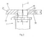
- FIG. 3shows a detailed view of connector 6 of bone anchoring element 35 coupled to a fixation plate 21 .
- Receiving cavity 19is spherical in shape and connector 6 can be snapped into receiving cavity 19 as a result of the elastic deformability of resilient tabs 14 .
- Receiving cavity 19is designed in such a manner that plane 17 , which is orthogonal to central axis 2 is a distance Y ⁇ X from top surface 16 of fixation plate 21 . These dimensions allow connector 6 to be pivotably coupled and supported in receiving cavity 19 .
- bone anchoring assembly 1comprises two bone anchoring elements 35 and two fixation plates 21 , 22 .
- Fixation plate 21has contacting surface 25 that is placed in contact with contacting surface 26 of fixation plate 22 when the two fixation plates are coupled together via elongated slots 38 and fastener 27 .
- the contacting surfaces 25 , 26are textured, typically in the form of serrations 28 , to help prevent fixation plates 21 , 22 from slipping when a load is placed on fixation plates 21 , 22 .
- fixation plates 21 , 22both have lateral lugs 41 which are located at the ends of contacting surfaces 25 , 26 . Lateral lugs 41 prevent fixation plates 21 , 22 from rotating relative to each other thereby becoming skewed with respect to central axis 30 .
- Circular-cylindrical bodies 3have a plurality of radial borehole passages 31 located along the outside surface of circular-cylindrical bodies 3 , have external threads 4 located at the posterior or upper ends of circular-cylindrical bodies 3 , and have cutting teeth 32 with radial cutting edges 33 located at the anterior or lower end of the bodies.
- Radial borehole passages 31provide a passageway to allow the osteoinductive material located within the borehole of circular-cylindrical bodies 3 to communicate with the bony tissue located outside of circular-cylindrical bodies 3 .
- External threads 4anchor circular-cylindrical bodies 3 to the bony tissue.
- Circular-cylindrical bodies 3also have flange 39 located at the posterior or upper end of the bodies.
- Flange 39preferably, has six semicircular notches 40 located equidistantly along the periphery of the flange. Through the use of notches 40 and a matching tool, circular-cylindrical body 3 can be rotated into bone.
- flange 39can be in the shape of a hexagon and a hexagonal tool can be used to rotate circular-cylindrical body 3 into bone. Further, flange 39 also acts as a stop to prevent circular-cylindrical bodies 3 from being rotated excessively deep into the bone.
- Circular-cylindrical bodies 3also have connectors 6 which are used to couple circular-cylindrical bodies 3 to fixation plates 21 , 22 .
- Connectors 6are spherical in shape with diameters that correspond to the size of the receiving boreholes 19 located in fixation plates 21 , 22 . Also, both connectors 6 are fitted with boreholes 34 that have internal threads 12 , a conically lathed geometry 13 , and a series of slits located along the periphery of connectors 6 . Screws 23 are inserted into boreholes 34 through receiving boreholes 19 wherein screw heads 24 fit within the conically lathed geometry 12 to fix circular-cylindrical bodies 3 to fixation plates 21 , 22 . More specifically, when screws 23 are tightened, resilient blades 14 of connectors 6 are clamped against the walls of receiving boreholes 19 thereby affixing circular-cylindrical bodies 3 to fixation plates 21 , 22 .
- the structure and means for affixing the circular-cylindrical bodies 3 to fixation plates 21 , 22 and for coupling fixation plates 21 , 22 togetherallow circular-cylindrical bodies 3 to be attached at various angles and distances from each other.
- the spherical structure of connecters 6allow circular-cylindrical bodies 3 to be pivotably supported and attached to fixation plates 21 , 22 at angle 29 which ranges from 16° inwardly from perpendicular axis 2 to 19° outwardly from perpendicular axis 2 .
- fastener 27which typically is in the form of a screw, is threadably received in borehole 37 which can be located any where within elongated slot 38 .
- fixation plates 21 , 22can be coupled together at various displacement distances Z, thereby varying the distance between circular-cylindrical bodies 3 .
- the insertion of the above described bone anchoring assemblydoes not require a previously drilled borehole or duct.
- the procedure for inserting and locking the bone anchoring assembly into a boneis very quick and quite simple.
- the first step in inserting the assembly into boneis to introduce a Kirschner wire into the bone.
- the Kirschner wireis used to guide circular-cylindrical bodies 3 as they are inserted into the bone.
- a first circular cylindrical body 3is rotated into the bone using flange 39 and a matching tool.
- cutting teeth 32 with radial cutting edges 33cut the bone creating bone chips which are guided into borehole 5 located within circular-cylindrical body 3 .
- External thread 4anchors circular-cylindrical body 3 in the bone.
- circular-cylindrical body 3is anchored only to the cortical portion of the bone and not to the spongy portion of the bone. Furthermore, since external thread 4 does not enter into the spongy portion of the bone, external thread 4 will not harm the spongy portion of the bone through micro-motion shears and notch effects.
- the Kirschner wiremay then be removed. A second circular-cylindrical body 3 is then inserted into the bone in the same manner as first circular-cylindrical body 3 .
- fixation plates 21 , 22are attached to circular-cylindrical bodies 3 by snapping connectors 6 into receiving boreholes 19 and inserting screws 23 through boreholes 34 located in connectors 6 and receiving boreholes 19 located in fixation plates 21 , 22 .
- Fastener 27is then threadably received through borehole 37 thereby coupling fixation plates 21 , 22 together.
- the bone anchoring assemblyas a whole, can then be locked in the desired position by tightening screws 23 and fastener 27 .
Landscapes
- Health & Medical Sciences (AREA)
- Orthopedic Medicine & Surgery (AREA)
- Life Sciences & Earth Sciences (AREA)
- Surgery (AREA)
- Neurology (AREA)
- Heart & Thoracic Surgery (AREA)
- Engineering & Computer Science (AREA)
- Biomedical Technology (AREA)
- Nuclear Medicine, Radiotherapy & Molecular Imaging (AREA)
- Medical Informatics (AREA)
- Molecular Biology (AREA)
- Animal Behavior & Ethology (AREA)
- General Health & Medical Sciences (AREA)
- Public Health (AREA)
- Veterinary Medicine (AREA)
- Surgical Instruments (AREA)
- Prostheses (AREA)
Abstract
Description
This application is a continuation of the U.S. National Stage designation of co-pending International Patent Application PCT/CH98/00360, filed Aug. 21, 1998, the entire content of which is expressly incorporated by reference.
The invention relates to a bone-anchoring assembly. More particularly, the invention relates to bone anchoring elements that are capable of being pivotably attached to osteosynthesis fixation plates or longitudinal support bars for the fixation of bone segments such as vertebrae.
Implants for fixation of bones such as bone plates, longitudinal support bars, pedicle screws, and bone anchoring assemblies increasingly are used in osteosynthesis applications. Such devices are useful for treating fractures of bones, for anchoring bone segments, or for providing support to bones weakened from disease or defect.
One such implant is disclosed in the German utility model DE 297 10 979 to Aesculap. The implant comprises a bone anchoring element that is insertable into a bone segment. The bone anchoring element can then be mounted using a detachable ball clamp to a connection element. The connection element, in turn, can be clamped to a longitudinal support or to another bone anchoring element. By connecting several bone anchoring elements together, bone segments or vertebra can be rigidly connected together. As disclosed in the German utility model, the anchoring elements are in the form of hollow, cylindrical bone screws that have an external threaded and are fitted with radial boreholes located between the threads. A ball joint pivtotably supports the bone screw in the connection element until the ball joint is locked by the ball clamp. However, the drawback to the disclosed implant is the dish-shaped seat of the ballhead of the bone screw only allows inserting the bone screw unilaterally from above into the connection element and, as a result, the bone screw and connection element must be screwed jointly into the bone.
PCT publication no. WO 96/08206 to Foley discloses an osteosynthesis device with an elongated bone fixation plate and several bone anchoring elements. The disclosed bone anchoring elements consist of bone screws with spherical and radially elastic screw heads. The bone screws are inserted into the fixation plate at the desired angle and conical fixation screws are inserted into the spherical screw head of the bone fixation screw, thereby radially expanding the screw head and fixing the screw at the desired angle in the bone plate. The drawback to the disclosed osteosynthesis device is that the bone screws must be actively supported at the desired angle of insertion until they can be fixed with the conical fixation screws. As a result, the disclosed device is difficult to implant.
A similar drawback is present in the osteosynthesis device disclosed in PCT publication no. WO 88/03781 to Raveh. The disclosed osteosynthesis device comprises a bone fixation plate and several bone screws used to fix the plate to the desired bone area. The bone screws disclosed in this application are inserted into the bone fixation plate at the desired angle and conical fixation screws are then inserted into the bone screw heads to expand and lock the bone screw heads into the bone fixation plate. Again, the drawback to the disclosed osteosynthesis device is that the bone screws must be actively supported at the desired angle of insertion until they can be fixed with the conical fixation screws.
Another osteosynthesis device comprising a bone fixation plate and bone fixation means is disclosed in published EPO application no. EP 0 809 075 to Benzel. The bone fixation means disclosed comprises a bone screw with a spherical head and a hollow shaft that is configured and dimensioned to threadably receive a bone expansion screw. The bone screw is inserted through the bone fixation plate at the desired angle into the bone and the bone expansion screw is then inserted into the bone screw to expand and lock the bone screw in at the desired angle in the bone plate and the bone. However, the drawback to this device is the same as the above devices in that the bone screws must be actively supported at the desired angle of insertion until they can be fixed with the bone expansion screws.
In light of the foregoing, it is clear that there exists a need for an improved bone anchoring element.
The present invention relates to a bone anchoring assembly having at least one bone anchoring element capable of being attached to at least one osteosynthesis plate or bar for the fixation of bone segments. The at least one bone anchoring element preferably includes a circular-cylindrical body with a hemi-spherical connecting element at the posterior or upper end of the body for coupling to another fixation element, a flange located at the upper end of the body for limiting the insertion depth of the bone anchoring element, a plurality of radial borehole passages located on the body of the bone anchoring element, an external, self-tapping thread that extends over a portion of the bone anchoring element, and teeth at the anterior or lower end of the body for cutting into bone.
In one preferred embodiment, the bone anchoring element consists of a circular-cylindrical hollow body fitted at one end with a hemi-spherical connector that is mounted concentrically with the bone anchoring element's central axis. The hemi-spherical connector is configured and dimensioned to be pivotably coupled to another fixation element such as a bone fixation plate or longitudinal support bars. Specifically, the hemi-spherical connector comprises a number of resilient blades, arranged in a circular pattern, that are radially displaceable either toward or away from the central axis of the bone anchoring element which allows the connector to be compressed or expanded thereby allowing it to snap into or out of a receiving cavity of the fixation element. Preferably, the connector blades are formed by slits running parallel to the central axis of the bone anchoring element along the periphery of the spherical connector. In addition, since the connector is shaped as a hemi-sphere and is radially deformable, the bone anchoring element can be pivotably coupled and supported in the receiving cavity of the fixation element.
The hemi-spherical connector, preferably, has a diameter D, a height of U, and a ratio of U/D that is between 0.4 and 0.7. Furthermore, the radially displaceable blades are elastically variable in a range between 0.95 to 1.05 of the diameter D. The connector can also be fixed at a particular position or angle through the use of conical fixation screws. The connector has a conically tapering bore located concentrically to the central axis of the bone anchoring element in which a conical fixation screw can be threadably received. Typically, the bone anchoring element is snapped into a receiving cavity of another implantable element and is positioned at the desired angle. A conical fixation screw is then inserted through the implantable element into the threaded bore located in the connector. As the conical fixation screw is tightened, the blades of the spherical connector are displaced outwardly locking the bone anchoring element at the desired angle to the implantable element.
In another preferred embodiment, the outside surface of the anterior or lower portion of the anchoring element does not contain an external thread allowing for a smooth surface with radial borehole passages. The radial borehole passages allow the osteoinductive material located within the hollow anchoring body to fuse with the bone located outside the anchoring body. In addition, the radial borehole passages reduce the amount of material needed to create the implant, thereby substantially lowering the total weight of the bone anchoring element.
In a further preferred embodiment, the bone anchoring apparatus comprises bone anchoring elements and plates fitted with receiving means the spherical connectors of the bone anchoring elements. The receiving means essentially consist of spherical cavities appropriately sized to allow the hemi-spherical connectors to snap into the cavity and be pivotably supported in the plate. Also, the bone anchoring element is detachably affixed to the plate by bone anchoring fasteners such as screws or nuts. Typically, the connector allows a 15° to 35° angular range of pivotal motion for the bone anchoring element with respect to the axis orthogonal to the plate surface. Each plate also has an elongated central channel that extends along a central axis, across most of the length of the plate, capable of receiving a fastener that will affix the plates together at any distance along the central axis within the central channel. Typically, the distance the two plates are displaceable from each other ranges between 20 mm to 60 mm. The fastener is preferably a screw or a bolt and the plates preferably have textured surfaces at their respective points of contact to prevent slippage of the plates with respect to each other and to increase the stability of the affixed plates. In addition, the plates preferably have lateral lugs to further prevent slippage and to prevent rotation of the plates with respect to each other.
Preferred features of the present invention are disclosed in the accompanying drawings, wherein similar reference characters denote similar elements throughout the several views, and wherein:
FIG. 1 shows a schematic view of a bone anchoring element of the present invention;
FIG. 2 shows a top view of the bone anchoring element of FIG. 1;
FIG. 3 shows a detailed view of the bone anchoring element of FIGS. 1 and 2 coupled to a fixation plate;
FIG. 4 shows a perspective view of a bone anchoring assembly of the present invention;
FIG. 5 shows a top view of the bone anchoring assembly of FIG.4.
Referring to FIGS. 1 and 2,bone anchoring element 35 ofbone anchoring assembly 1 is shown schematically. In a preferred embodiment,bone anchoring element 35 comprises circular-cylindrical body 3, hemi-spherical connector 6, andflange 39. Circular-cylindrical body 3 defines acentral axis 2 andupper end 10 andlower end 11.
Circular-cylindrical body 3 has a certain height, designated as H. Circular-cylindrical body 3 also hasconcentric borehole 5 which, measured fromlower surface 11, has a depth of T. Thus, circular-cylindrical body 3 is hollow over a length corresponding to the depth of T. The outer surface of circular-cylindrical body 3 is smooth over the anterior or lower portion of circular-cylindrical body 3 while the remaining portion of the outer surface contains an external thread and, accordingly, is not smooth. Atupper end 10, circular-cylindrical body 3 is fitted withflange 39 which has a diameter larger than the diameter of circular-cylindrical body 3.Flange 39 is fitted with six equidistantsemicircular notches 40 located on the periphery offlange 39. Usingnotches 40 onflange 39 with a matching tool,bone anchoring element 35 can be rotated into the bone. Alternatively, in place ofnotches 40,flange 39 can be shaped hexagonally and with a matching hexagonal tool,bone anchoring element 35 can be rotated into the bone. In addition,flange 39 ensures thatbone anchoring element 35 is not rotated unduly deeply into the bone by providing a stop that preventsbone anchoring element 35 from rotating further into the bone.
FIG. 3 shows a detailed view ofconnector 6 ofbone anchoring element 35 coupled to afixation plate 21. Receivingcavity 19 is spherical in shape andconnector 6 can be snapped into receivingcavity 19 as a result of the elastic deformability ofresilient tabs 14. Receivingcavity 19 is designed in such a manner thatplane 17, which is orthogonal tocentral axis 2 is a distance Y<X fromtop surface 16 offixation plate 21. These dimensions allowconnector 6 to be pivotably coupled and supported in receivingcavity 19.
Turning now to FIGS. 4 and 5, another preferred embodiment ofbone anchoring assembly 1 is shown. In this embodiment,bone anchoring assembly 1 comprises twobone anchoring elements 35 and twofixation plates fixation plates central axis 30.Fixation plate 21 has contactingsurface 25 that is placed in contact with contactingsurface 26 offixation plate 22 when the two fixation plates are coupled together viaelongated slots 38 andfastener 27. The contacting surfaces25,26 are textured, typically in the form of serrations28, to help preventfixation plates fixation plates fixation plates lateral lugs 41 which are located at the ends of contactingsurfaces fixation plates central axis 30.
Circular-cylindrical bodies 3 have a plurality ofradial borehole passages 31 located along the outside surface of circular-cylindrical bodies 3, haveexternal threads 4 located at the posterior or upper ends of circular-cylindrical bodies 3, and have cuttingteeth 32 with radial cutting edges33 located at the anterior or lower end of the bodies.Radial borehole passages 31 provide a passageway to allow the osteoinductive material located within the borehole of circular-cylindrical bodies 3 to communicate with the bony tissue located outside of circular-cylindrical bodies 3.External threads 4 anchor circular-cylindrical bodies 3 to the bony tissue. Circular-cylindrical bodies 3 also haveflange 39 located at the posterior or upper end of the bodies.Flange 39, preferably, has sixsemicircular notches 40 located equidistantly along the periphery of the flange. Through the use ofnotches 40 and a matching tool, circular-cylindrical body 3 can be rotated into bone. Alternatively,flange 39 can be in the shape of a hexagon and a hexagonal tool can be used to rotate circular-cylindrical body 3 into bone. Further,flange 39 also acts as a stop to prevent circular-cylindrical bodies 3 from being rotated excessively deep into the bone. Circular-cylindrical bodies 3 also haveconnectors 6 which are used to couple circular-cylindrical bodies 3 tofixation plates Connectors 6 are spherical in shape with diameters that correspond to the size of the receivingboreholes 19 located infixation plates connectors 6 are fitted withboreholes 34 that haveinternal threads 12, a conically lathedgeometry 13, and a series of slits located along the periphery ofconnectors 6.Screws 23 are inserted intoboreholes 34 through receivingboreholes 19 wherein screw heads24 fit within the conically lathedgeometry 12 to fix circular-cylindrical bodies 3 tofixation plates resilient blades 14 ofconnectors 6 are clamped against the walls of receivingboreholes 19 thereby affixing circular-cylindrical bodies 3 tofixation plates
The structure and means for affixing the circular-cylindrical bodies 3 tofixation plates coupling fixation plates cylindrical bodies 3 to be attached at various angles and distances from each other. For example, the spherical structure ofconnecters 6 allow circular-cylindrical bodies 3 to be pivotably supported and attached tofixation plates angle 29 which ranges from 16° inwardly fromperpendicular axis 2 to 19° outwardly fromperpendicular axis 2. In addition,fastener 27, which typically is in the form of a screw, is threadably received inborehole 37 which can be located any where within elongatedslot 38. By usingelongated slot 38 withborehole 37,fixation plates cylindrical bodies 3.
The insertion of the above described bone anchoring assembly does not require a previously drilled borehole or duct. The procedure for inserting and locking the bone anchoring assembly into a bone is very quick and quite simple. The first step in inserting the assembly into bone is to introduce a Kirschner wire into the bone. The Kirschner wire is used to guide circular-cylindrical bodies 3 as they are inserted into the bone. A first circularcylindrical body 3 is rotated into thebone using flange 39 and a matching tool. As circular-cylindrical body 1 is rotated into the bone, cuttingteeth 32 with radial cutting edges33 cut the bone creating bone chips which are guided intoborehole 5 located within circular-cylindrical body 3.External thread 4 anchors circular-cylindrical body 3 in the bone. Sinceexternal thread 4 is present only on the upper portion of circular-cylindrical body 3, circular-cylindrical body 3 is anchored only to the cortical portion of the bone and not to the spongy portion of the bone. Furthermore, sinceexternal thread 4 does not enter into the spongy portion of the bone,external thread 4 will not harm the spongy portion of the bone through micro-motion shears and notch effects. After first circular-cylindrical body 3 has been screwed into the bone, the Kirschner wire may then be removed. A second circular-cylindrical body 3 is then inserted into the bone in the same manner as first circular-cylindrical body 3. After circular-cylindrical bodies 3 have been inserted into the bone,fixation plates cylindrical bodies 3 by snappingconnectors 6 into receivingboreholes 19 and insertingscrews 23 throughboreholes 34 located inconnectors 6 and receivingboreholes 19 located infixation plates Fastener 27 is then threadably received throughborehole 37 thereby couplingfixation plates screws 23 andfastener 27.
While it is apparent that the illustrative embodiments of the invention herein disclosed fulfill the objectives stated above, it will be appreciated that numerous modifications and other embodiments may be devised by those skilled in the art. Therefore, it will be understood that the appended claims are intended to cover all such modifications and embodiments which come within the spirit and scope of the present invention.
Claims (48)
1. A bone anchoring element comprising:
a hollow cylindrical body comprising an upper end, a lower end, and an exterior surface, the exterior surface having a threaded portion and an unthreaded portion, the unthreaded portion located substantially adjacent to the lower end of the body;
a hemi-spherical connector with a diameter and a height mounted at the upper end of the body for coupling to a fixation device,
wherein the connector comprises a number of resilient blades formed by a number of slits on the connector thereby allowing the connector to be elastically compressible or expandable.
2. The bone anchoring element ofclaim 1 , wherein the threading is located substantially adjacent to the upper end of the body for anchoring the body into surrounding bony tissue.
3. The bone anchoring element ofclaim 2 , wherein threading is self-tapping.
4. The bone anchoring element ofclaim 2 , further comprising a plurality of radial boreholes on the external surface of the body.
5. The bone anchoring element ofclaim 1 , further comprising at least one tooth extending from the lower end of the body for cutting bone.
6. The bone anchoring element ofclaim 1 , further comprising a flange located at the upper end of the body for limiting insertion depth of the bone anchoring element.
7. The bone anchoring element ofclaim 6 , wherein the flange has a plurality of notches for receiving an insertion tool.
8. The bone anchoring element ofclaim 6 , wherein the flange is hexagonal.
9. The bone anchoring element ofclaim 1 , wherein the connector has a borehole for receiving a fastener.
10. The bone anchoring element ofclaim 9 , wherein an inner surface of the borehole is threaded.
11. The bone anchoring element ofclaim 9 , wherein the borehole conically tapers from an upper end to a lower end over a portion of its length.
12. The bone anchoring element ofclaim 1 , wherein the ratio of the height to the diameter of the connector is between 0.4 and 0.7.
13. The bone anchoring element ofclaim 1 , wherein the blades are elastically compressible or expandable from a range of 0.95 to 1.05 times the diameter of the connector.
14. A bone anchoring assembly comprising:
the bone anchoring element ofclaim 1 ; and
a first fixation plate having a first end, a second end, and a central axis,
wherein, an elongated slot is located along the central axis at the first end of the first fixation plate and a borehole configured and dimensioned to pivotably receive and support the connector of the bone anchoring element is located at the second end of the first fixation plate.
15. The bone anchoring assembly ofclaim 14 , wherein the bone anchoring element can pivot between 0° and 35° from a plane perpendicular to the first fixation plate.
16. The bone anchoring assembly ofclaim 14 , further comprising:
a second bone anchoring element; and
a second fixation plate having a first end, a second end, and a central axis,
wherein an elongated slot is located along the central axis at the first end of the second fixation plate and a borehole configured and dimensioned to pivotably receive and support the second bone anchoring element is located at the second end of the plate, and
wherein the elongated slots of the first and second fixation plates are configured and dimensioned to receive a fastener thereby allowing the first and second fixation plates to be coupled together at varying separation distances along the central axis and wherein the connectors of the first and second bone anchoring elements have boreholes configured and dimensioned to receive fasteners allowing the bone anchoring elements to be detachably affixed to the first and second fixation plates.
17. The bone anchoring assembly ofclaim 16 , wherein the separation distance between the bone anchoring elements can be varied between 20 mm and 60 mm.
18. The bone anchoring assembly ofclaim 16 , wherein the fixation plate have lateral extension at the first end of each fixation plate for limiting the rotation of the fixation plates with respect to the central axis.
19. The bone anchoring assembly ofclaim 16 , wherein the first end of each fixation plate is textured.
20. A bone anchoring element comprising:
a hollow cylindrical body with upper end and lower ends;
a flange located at the upper end of the body for limiting insertion depth of the bone anchoring element;
a hemi-spherical connector with a diameter and a height mounted at the upper end of the body for coupling to a fixation device,
wherein the connector comprises a number of resilient blades formed by a number of slits on the connector thereby allowing the connector to be elastically compressible or expandable.
21. The bone anchoring element ofclaim 20 , wherein the flange is hexagonal.
22. The bone anchoring element ofclaim 21 , wherein the flange has a plurality of notches for receiving an insertion tool.
23. The bone anchoring element ofclaim 20 , wherein the connector has a borehole for receiving a fastener and wherein an inner surface of the borehole is threaded.
24. The bone anchoring element ofclaim 20 , wherein the ratio of the height to the diameter of the connector is between 0.4 and 0.7.
25. The bone anchoring element ofclaim 20 , wherein the blades are elastically compressible or expandable from a range of 0.95 to 1.05 times the diameter of the connector.
26. A bone anchoring element comprising:
a hollow cylindrical body with upper and lower ends; and
a hemi-spherical connector with a diameter and a height mounted at the upper end of the body for coupling to a fixation device,
wherein the connector comprises a number of resilient blades formed by a number of slits on the connector thereby allowing the connector to be elastically compressible or expandable and wherein the ratio of the height to the diameter of the connector is between 0.4 and 0.7.
27. The bone anchoring element ofclaim 26 , wherein the blades are elastically compressible or expandable from a range of 0.95 to 1.05 times the diameter of the connector.
28. The bone anchoring element ofclaim 26 , further comprising at least one tooth extending from the lower end of the body for cutting bone.
29. The bone anchoring element ofclaim 26 , further comprising a flange located at the upper end of the body for limiting insertion depth of the bone anchoring element.
30. The bone anchoring element ofclaim 26 , wherein the flange has a plurality of notches for receiving an insertion tool.
31. The bone anchoring element ofclaim 26 , wherein an inner surface of the borehole is threaded.
32. A bone anchoring element comprising:
a hollow cylindrical body with upper and lower ends;
at least one tooth extending from the lower end of the body for cutting bone; and
a hemi-spherical connector with a diameter and a height mounted at the upper end of the body for coupling to a fixation device,
wherein the connector comprises a number of resilient blades formed by a number of slits on the connector thereby allowing the connector to be elastically compressible or expandable.
33. The bone anchoring element ofclaim 32 , further comprising a plurality of radial boreholes on the external surface of the body.
34. A bone anchoring element comprising:
a hollow cylindrical body with upper and lower ends;
a hemi-spherical connector with a diameter and a height mounted at the upper end of the body for coupling to a fixation device; and
a flange located at the upper end of the body for limiting the insertion depth of the bone anchoring element,
wherein the connector comprises a number of resilient blades formed by a number of slits on the connector thereby allowing the connector to be elastically compressible or expandable and wherein the flange has a plurality of notches for receiving an insertion tool.
35. The bone anchoring element ofclaim 34 , wherein the flange is hexagonal.
36. The bone anchoring element ofclaim 34 , wherein an inner surface of the borehole is threaded.
37. The bone anchoring element ofclaim 36 , wherein the body has an exterior surface, the exterior surface having a threaded portion and an unthreaded portion, the unthreaded portion located substantially adjacent to the lower end of the body.
38. The bone anchoring element ofclaim 34 , wherein the ratio of the height to the diameter of the connector is between 0.4 and 0.7.
39. The bone anchoring element ofclaim 38 , wherein the blades are elastically compressible or expandable from a range of 0.95 to 1.05 times the diameter of the connector.
40. The bone anchoring element ofclaim 34 , further comprising a plurality of radial boreholes on the external surface of the body.
41. A bone anchoring assembly comprising:
a hollow cylindrical body with upper and lower ends;
a hemi-spherical connector with a diameter and a height mounted at the upper end of the body for coupling to a fixation device; and
a first fixation plate having a first end, a second end, and a central axis,
wherein the connector comprises a number of resilient blades formed by a number of slits on the connector thereby allowing the connector to be elastically compressible or expandable and wherein an elongated slot extending along substantially the length of the plate is located along the central axis beginning at the first end of the first fixation plate and a borehole configured and dimensioned to pivotably receive and support the connector of the bone anchoring element is located at the second end of the first fixation plate.
42. The bone anchoring assembly ofclaim 41 , further comprising:
a second bone anchoring element; and
a second fixation plate having a first end, a second end, and a central axis,
wherein an elongated slot is located along the central axis at the first end of the second fixation plate and a borehole configured and dimensioned to pivotably receive and support the second bone anchoring element is located at the second end of the plate, and
wherein the elongated slots of the first and second fixation plates are configured and dimensioned to receive a fastener thereby allowing the first and second fixation plates to be coupled together at varying separation distances along the central axis and wherein the connectors of the first and second bone anchoring elements have boreholes configured and dimensioned to receive fasteners allowing the bone anchoring elements to be detachably affixed to the first and second fixation plates.
43. The bone anchoring assembly ofclaim 41 , wherein the separation distance between the bone anchoring elements can be varied between 20 mm and 60 mm.
44. The bone anchoring assembly ofclaim 41 , wherein the first end of each fixation plate is textured.
45. The bone anchoring assembly ofclaim 41 , wherein the fixation plates have lateral extensions at the first end of each fixation plate for limiting the rotation of the fixation plates with respect to the central axis.
46. The bone anchoring assembly ofclaim 41 , wherein the bone anchoring element can pivot between 0° and 35° from a plane perpendicular to the first fixation plate.
47. A bone anchoring assembly comprising:
a hollow cylindrical body with upper and lower ends;
a hemi-spherical connector with a diameter and a height mounted at the upper end of the body for coupling to a fixation device; and
a first fixation plate having a first end, a second end, and a central axis,
wherein the connector comprises a number of resilient blades formed by a number of slits on the connector thereby allowing the connector to be elastically compressible or expandable and wherein an elongated slot is located along the central axis at the first end of the first fixation plate and a borehole configured and dimensioned to pivotably receive and support the connector of the bone anchoring element is located at the second end of the first fixation plate and wherein the width of the fixation plate near the elongated bore is approximately one half the width of the plate near the borehole.
48. A bone anchoring assembly comprising:
a hollow cylindrical body with upper and lower ends;
a hemi-spherical connector with a diameter and a height mounted at the upper end of the body for coupling to a fixation device; and
a first fixation plate having a first end, a second end, and a central axis,
wherein the connector comprises a number of resilient blades formed by a number of slits on the connector thereby allowing the connector to be elastically compressible or expandable and wherein an elongated slot approximately twice as long as it is wide is located along the central axis at the first end of the first fixation plate and a borehole configured and dimensioned to pivotably receive and support the connector of the bone anchoring element is located at the second end of the first fixation plate.
Applications Claiming Priority (1)
| Application Number | Priority Date | Filing Date | Title |
|---|---|---|---|
| PCT/CH1998/000360WO2000010474A1 (en) | 1998-08-21 | 1998-08-21 | Bone-anchoring element with snap-in spherical head |
Related Parent Applications (1)
| Application Number | Title | Priority Date | Filing Date |
|---|---|---|---|
| PCT/CH1998/000360ContinuationWO2000010474A1 (en) | 1998-08-21 | 1998-08-21 | Bone-anchoring element with snap-in spherical head |
Publications (2)
| Publication Number | Publication Date |
|---|---|
| US20010007941A1 US20010007941A1 (en) | 2001-07-12 |
| US6508818B2true US6508818B2 (en) | 2003-01-21 |
Family
ID=4551345
Family Applications (1)
| Application Number | Title | Priority Date | Filing Date |
|---|---|---|---|
| US09/788,483Expired - LifetimeUS6508818B2 (en) | 1998-08-21 | 2001-02-21 | Bone anchoring assembly with a snap-in ballhead |
Country Status (7)
| Country | Link |
|---|---|
| US (1) | US6508818B2 (en) |
| EP (1) | EP1105059A1 (en) |
| JP (1) | JP2002523129A (en) |
| AU (1) | AU747042B2 (en) |
| CA (1) | CA2341305A1 (en) |
| WO (1) | WO2000010474A1 (en) |
| ZA (1) | ZA994847B (en) |
Cited By (137)
| Publication number | Priority date | Publication date | Assignee | Title |
|---|---|---|---|---|
| US20010007072A1 (en)* | 1998-08-21 | 2001-07-05 | Beatrice Steiner | Self-cutting, hollow-cylindrical bone anchoring assembly |
| US20020133159A1 (en)* | 2000-12-08 | 2002-09-19 | Jackson Roger P. | Closure for open-headed medical implant |
| US20040138748A1 (en)* | 2000-03-22 | 2004-07-15 | Synthes (Usa) | Plugs for filling bony defects |
| US20040167526A1 (en)* | 2002-09-06 | 2004-08-26 | Roger P. Jackson | Closure for rod receiving orthopedic implant having left handed thread removal |
| US20040172032A1 (en)* | 2002-09-06 | 2004-09-02 | Jackson Roger P. | Anti-splay medical implant closure with multi-surface removal aperture |
| US20040199164A1 (en)* | 2002-09-06 | 2004-10-07 | Jackson Roger P. | Helical wound mechanically interlocking mating guide and advancement structure |
| US20040236329A1 (en)* | 2003-05-02 | 2004-11-25 | Panjabi Manohar M. | Dynamic spine stabilizer |
| US20050033298A1 (en)* | 2001-10-31 | 2005-02-10 | Ortho Development Corporation | Cervical plate for stabilizing the human spine |
| US20050159813A1 (en)* | 2004-01-15 | 2005-07-21 | Molz Fred J.Iv | Spinal implant construct and method for implantation |
| US20050171543A1 (en)* | 2003-05-02 | 2005-08-04 | Timm Jens P. | Spine stabilization systems and associated devices, assemblies and methods |
| US20050177164A1 (en)* | 2003-05-02 | 2005-08-11 | Carmen Walters | Pedicle screw devices, systems and methods having a preloaded set screw |
| US20050177156A1 (en)* | 2003-05-02 | 2005-08-11 | Timm Jens P. | Surgical implant devices and systems including a sheath member |
| US20050177166A1 (en)* | 2003-05-02 | 2005-08-11 | Timm Jens P. | Mounting mechanisms for pedicle screws and related assemblies |
| US20050182401A1 (en)* | 2003-05-02 | 2005-08-18 | Timm Jens P. | Systems and methods for spine stabilization including a dynamic junction |
| US20050182410A1 (en)* | 2002-09-06 | 2005-08-18 | Jackson Roger P. | Helical guide and advancement flange with radially loaded lip |
| US20050182409A1 (en)* | 2003-05-02 | 2005-08-18 | Ronald Callahan | Systems and methods accommodating relative motion in spine stabilization |
| US20050245930A1 (en)* | 2003-05-02 | 2005-11-03 | Timm Jens P | Dynamic spine stabilizer |
| US20050288670A1 (en)* | 2004-06-23 | 2005-12-29 | Panjabi Manohar M | Dynamic stabilization device including overhanging stabilizing member |
| US20060009773A1 (en)* | 2002-09-06 | 2006-01-12 | Jackson Roger P | Helical interlocking mating guide and advancement structure |
| US20060111712A1 (en)* | 2004-11-23 | 2006-05-25 | Jackson Roger P | Spinal fixation tool set and method |
| US20060167456A1 (en)* | 2004-12-21 | 2006-07-27 | Packaging Service Corporation Of Kentucky | Cervical plate system |
| US20060200128A1 (en)* | 2003-04-04 | 2006-09-07 | Richard Mueller | Bone anchor |
| US20060229613A1 (en)* | 2004-12-31 | 2006-10-12 | Timm Jens P | Sheath assembly for spinal stabilization device |
| US20060241603A1 (en)* | 2003-06-18 | 2006-10-26 | Jackson Roger P | Polyaxial bone screw assembly with fixed retaining structure |
| US20060271047A1 (en)* | 2005-05-10 | 2006-11-30 | Jackson Roger P | Polyaxial bone screw with compound articulation |
| US20070032123A1 (en)* | 2005-08-03 | 2007-02-08 | Timm Jens P | Spring junction and assembly methods for spinal device |
| US20070043356A1 (en)* | 2005-07-26 | 2007-02-22 | Timm Jens P | Dynamic spine stabilization device with travel-limiting functionality |
| US20070055244A1 (en)* | 2004-02-27 | 2007-03-08 | Jackson Roger P | Dynamic fixation assemblies with inner core and outer coil-like member |
| US20070093813A1 (en)* | 2005-10-11 | 2007-04-26 | Callahan Ronald Ii | Dynamic spinal stabilizer |
| US20070093815A1 (en)* | 2005-10-11 | 2007-04-26 | Callahan Ronald Ii | Dynamic spinal stabilizer |
| US20070093814A1 (en)* | 2005-10-11 | 2007-04-26 | Callahan Ronald Ii | Dynamic spinal stabilization systems |
| US20070244481A1 (en)* | 2006-04-17 | 2007-10-18 | Timm Jens P | Spinal stabilization device with weld cap |
| US20070270860A1 (en)* | 2005-09-30 | 2007-11-22 | Jackson Roger P | Dynamic stabilization connecting member with slitted core and outer sleeve |
| US20070293862A1 (en)* | 2005-09-30 | 2007-12-20 | Jackson Roger P | Dynamic stabilization connecting member with elastic core and outer sleeve |
| US20080140136A1 (en)* | 2003-06-18 | 2008-06-12 | Jackson Roger P | Polyaxial bone screw with cam capture |
| US20080147122A1 (en)* | 2006-10-12 | 2008-06-19 | Jackson Roger P | Dynamic stabilization connecting member with molded inner segment and surrounding external elastomer |
| US20080188898A1 (en)* | 2004-11-23 | 2008-08-07 | Jackson Roger P | Polyaxial bone screw with multi-part shank retainer and pressure insert |
| US20080234761A1 (en)* | 2003-06-18 | 2008-09-25 | Jackson Roger P | Polyaxial bone screw with shank-retainer insert capture |
| US20080234759A1 (en)* | 2005-04-27 | 2008-09-25 | Trinity Orthopedics, Llc | Mono-Planar Pedicle Screw Method, System and Kit |
| US20080294198A1 (en)* | 2006-01-09 | 2008-11-27 | Jackson Roger P | Dynamic spinal stabilization assembly with torsion and shear control |
| US20080300633A1 (en)* | 2007-05-31 | 2008-12-04 | Jackson Roger P | Dynamic stabilization connecting member with pre-tensioned solid core |
| US20080319482A1 (en)* | 2007-01-18 | 2008-12-25 | Jackson Roger P | Dynamic fixation assemblies with pre-tensioned cord segments |
| US20090062866A1 (en)* | 2003-06-18 | 2009-03-05 | Jackson Roger P | Polyaxial bone anchor with helical capture connection, insert and dual locking assembly |
| US20090105820A1 (en)* | 2007-10-23 | 2009-04-23 | Jackson Roger P | Dynamic stabilization member with fin support and cable core extension |
| US20090105764A1 (en)* | 2007-10-23 | 2009-04-23 | Jackson Roger P | Dynamic stabilization member with fin support and solid core extension |
| US20090281574A1 (en)* | 2007-02-12 | 2009-11-12 | Jackson Roger P | Dynamic stabilization assembly with frusto-conical connection |
| US20100010543A1 (en)* | 2007-05-01 | 2010-01-14 | Jackson Roger P | Dynamic stabilization connecting member with floating core, compression spacer and over-mold |
| US20100125302A1 (en)* | 2008-11-14 | 2010-05-20 | Hammill Sr John E | Locking Polyaxial Ball And Socket Fastener |
| US20100137920A1 (en)* | 2007-05-16 | 2010-06-03 | Hammill Sr John E | Pedicle screw implant system |
| US20100211114A1 (en)* | 2003-06-18 | 2010-08-19 | Jackson Roger P | Polyaxial bone anchor with shelf capture connection |
| US20100249937A1 (en)* | 2009-03-27 | 2010-09-30 | Spinal Elements, Inc. | Flanged interbody fusion device |
| US20100268281A1 (en)* | 2005-12-19 | 2010-10-21 | Abdou M Samy | Devices and methods for inter-vertebral orthopedic device placement |
| US20100318136A1 (en)* | 2003-06-18 | 2010-12-16 | Jackson Roger P | Polyaxial bone screw assembly |
| US20100331887A1 (en)* | 2006-01-09 | 2010-12-30 | Jackson Roger P | Longitudinal connecting member with sleeved tensioned cords |
| US7901437B2 (en) | 2007-01-26 | 2011-03-08 | Jackson Roger P | Dynamic stabilization member with molded connection |
| US20110098755A1 (en)* | 2009-06-15 | 2011-04-28 | Jackson Roger P | Polyaxial bone anchor with non-pivotable retainer and pop-on shank, some with friction fit |
| US7942909B2 (en) | 2009-08-13 | 2011-05-17 | Ortho Innovations, Llc | Thread-thru polyaxial pedicle screw system |
| US7942910B2 (en) | 2007-05-16 | 2011-05-17 | Ortho Innovations, Llc | Polyaxial bone screw |
| US7942911B2 (en) | 2007-05-16 | 2011-05-17 | Ortho Innovations, Llc | Polyaxial bone screw |
| US20110137352A1 (en)* | 2009-12-03 | 2011-06-09 | Lutz Biedermann | Bone screw |
| US20110137354A1 (en)* | 2009-12-03 | 2011-06-09 | Lutz Biedermann | Bone screw |
| US20110144469A1 (en)* | 2008-05-07 | 2011-06-16 | Patraicia Connolly | Bacterial/Cellular Recognition Impedance Algorithm |
| US20110218578A1 (en)* | 2003-06-18 | 2011-09-08 | Jackson Roger P | Polyaxial bone screw with cam connection and lock and release insert |
| US20110224793A1 (en)* | 2008-04-01 | 2011-09-15 | Fortin Frederic | Base Piece That Can Be Adjusted Prior To Its Attachment, And Can Be Easily Incorporated Into A Device Replacing A Corpus Vertebrae |
| US8066739B2 (en) | 2004-02-27 | 2011-11-29 | Jackson Roger P | Tool system for dynamic spinal implants |
| US8075603B2 (en) | 2008-11-14 | 2011-12-13 | Ortho Innovations, Llc | Locking polyaxial ball and socket fastener |
| US8092502B2 (en) | 2003-04-09 | 2012-01-10 | Jackson Roger P | Polyaxial bone screw with uploaded threaded shank and method of assembly and use |
| US8100915B2 (en) | 2004-02-27 | 2012-01-24 | Jackson Roger P | Orthopedic implant rod reduction tool set and method |
| US20120029639A1 (en)* | 2010-07-29 | 2012-02-02 | Warsaw Orthopedic, Inc. | Interbody spinal implants and insertion techniques |
| US8137386B2 (en) | 2003-08-28 | 2012-03-20 | Jackson Roger P | Polyaxial bone screw apparatus |
| US8197518B2 (en) | 2007-05-16 | 2012-06-12 | Ortho Innovations, Llc | Thread-thru polyaxial pedicle screw system |
| US20120203229A1 (en)* | 2010-08-13 | 2012-08-09 | Andreas Appenzeller | Bone Stabilization Device |
| US8308782B2 (en) | 2004-11-23 | 2012-11-13 | Jackson Roger P | Bone anchors with longitudinal connecting member engaging inserts and closures for fixation and optional angulation |
| US8353932B2 (en) | 2005-09-30 | 2013-01-15 | Jackson Roger P | Polyaxial bone anchor assembly with one-piece closure, pressure insert and plastic elongate member |
| US8366745B2 (en) | 2007-05-01 | 2013-02-05 | Jackson Roger P | Dynamic stabilization assembly having pre-compressed spacers with differential displacements |
| US8377102B2 (en) | 2003-06-18 | 2013-02-19 | Roger P. Jackson | Polyaxial bone anchor with spline capture connection and lower pressure insert |
| US8444681B2 (en) | 2009-06-15 | 2013-05-21 | Roger P. Jackson | Polyaxial bone anchor with pop-on shank, friction fit retainer and winged insert |
| US8454694B2 (en) | 2011-03-03 | 2013-06-04 | Warsaw Orthopedic, Inc. | Interbody device and plate for spinal stabilization and instruments for positioning same |
| US8475498B2 (en) | 2007-01-18 | 2013-07-02 | Roger P. Jackson | Dynamic stabilization connecting member with cord connection |
| US8480747B2 (en) | 2010-08-11 | 2013-07-09 | Warsaw Orthopedic, Inc. | Interbody spinal implants with extravertebral support plates |
| US20130238095A1 (en)* | 2012-03-06 | 2013-09-12 | Nicholas Pavento | Nubbed Plate |
| US8591515B2 (en) | 2004-11-23 | 2013-11-26 | Roger P. Jackson | Spinal fixation tool set and method |
| US8696721B2 (en) | 2005-03-17 | 2014-04-15 | Spinal Elements, Inc. | Orthopedic expansion fastener |
| US8814913B2 (en) | 2002-09-06 | 2014-08-26 | Roger P Jackson | Helical guide and advancement flange with break-off extensions |
| US20140277502A1 (en)* | 2013-03-15 | 2014-09-18 | NuTech Spine, Inc. | Anterior Lumbar Fusion Method and Device |
| US8845649B2 (en) | 2004-09-24 | 2014-09-30 | Roger P. Jackson | Spinal fixation tool set and method for rod reduction and fastener insertion |
| US8911479B2 (en) | 2012-01-10 | 2014-12-16 | Roger P. Jackson | Multi-start closures for open implants |
| US8936623B2 (en) | 2003-06-18 | 2015-01-20 | Roger P. Jackson | Polyaxial bone screw assembly |
| US8979904B2 (en) | 2007-05-01 | 2015-03-17 | Roger P Jackson | Connecting member with tensioned cord, low profile rigid sleeve and spacer with torsion control |
| US8998959B2 (en) | 2009-06-15 | 2015-04-07 | Roger P Jackson | Polyaxial bone anchors with pop-on shank, fully constrained friction fit retainer and lock and release insert |
| US20150100126A1 (en)* | 2013-10-07 | 2015-04-09 | Warsaw Orthopedic, Inc. | Spinal implant system and method |
| US9050139B2 (en) | 2004-02-27 | 2015-06-09 | Roger P. Jackson | Orthopedic implant rod reduction tool set and method |
| US9168069B2 (en) | 2009-06-15 | 2015-10-27 | Roger P. Jackson | Polyaxial bone anchor with pop-on shank and winged insert with lower skirt for engaging a friction fit retainer |
| US9198695B2 (en) | 2010-08-30 | 2015-12-01 | Zimmer Spine, Inc. | Polyaxial pedicle screw |
| US9198702B2 (en) | 2010-02-26 | 2015-12-01 | Biedermann Technologies Gmbh & Co. Kg | Bone screw |
| US9216041B2 (en) | 2009-06-15 | 2015-12-22 | Roger P. Jackson | Spinal connecting members with tensioned cords and rigid sleeves for engaging compression inserts |
| US9216039B2 (en) | 2004-02-27 | 2015-12-22 | Roger P. Jackson | Dynamic spinal stabilization assemblies, tool set and method |
| US9414863B2 (en) | 2005-02-22 | 2016-08-16 | Roger P. Jackson | Polyaxial bone screw with spherical capture, compression insert and alignment and retention structures |
| US9451989B2 (en) | 2007-01-18 | 2016-09-27 | Roger P Jackson | Dynamic stabilization members with elastic and inelastic sections |
| US9453526B2 (en) | 2013-04-30 | 2016-09-27 | Degen Medical, Inc. | Bottom-loading anchor assembly |
| US9480517B2 (en) | 2009-06-15 | 2016-11-01 | Roger P. Jackson | Polyaxial bone anchor with pop-on shank, shank, friction fit retainer, winged insert and low profile edge lock |
| US9526620B2 (en) | 2009-03-30 | 2016-12-27 | DePuy Synthes Products, Inc. | Zero profile spinal fusion cage |
| US9687354B2 (en) | 2008-03-26 | 2017-06-27 | DePuy Synthes Products, Inc. | Posterior intervertebral disc inserter and expansion techniques |
| US9743957B2 (en) | 2004-11-10 | 2017-08-29 | Roger P. Jackson | Polyaxial bone screw with shank articulation pressure insert and method |
| US9980753B2 (en) | 2009-06-15 | 2018-05-29 | Roger P Jackson | pivotal anchor with snap-in-place insert having rotation blocking extensions |
| US10034771B2 (en) | 2016-05-11 | 2018-07-31 | Warsaw Orthopedic, Inc. | Spinal implant system and method |
| US10039578B2 (en) | 2003-12-16 | 2018-08-07 | DePuy Synthes Products, Inc. | Methods and devices for minimally invasive spinal fixation element placement |
| US10159582B2 (en) | 2011-09-16 | 2018-12-25 | DePuy Synthes Products, Inc. | Removable, bone-securing cover plate for intervertebral fusion cage |
| US10182921B2 (en) | 2012-11-09 | 2019-01-22 | DePuy Synthes Products, Inc. | Interbody device with opening to allow packing graft and other biologics |
| US10194951B2 (en) | 2005-05-10 | 2019-02-05 | Roger P. Jackson | Polyaxial bone anchor with compound articulation and pop-on shank |
| US10206787B2 (en) | 2006-12-22 | 2019-02-19 | Medos International Sarl | Composite vertebral spacers and instrument |
| US10299839B2 (en) | 2003-12-16 | 2019-05-28 | Medos International Sárl | Percutaneous access devices and bone anchor assemblies |
| US10335289B2 (en) | 2010-09-23 | 2019-07-02 | DePuy Synthes Products, Inc. | Stand alone intervertebral fusion device |
| US10363070B2 (en) | 2009-06-15 | 2019-07-30 | Roger P. Jackson | Pivotal bone anchor assemblies with pressure inserts and snap on articulating retainers |
| US10369015B2 (en) | 2010-09-23 | 2019-08-06 | DePuy Synthes Products, Inc. | Implant inserter having a laterally-extending dovetail engagement feature |
| US10383660B2 (en) | 2007-05-01 | 2019-08-20 | Roger P. Jackson | Soft stabilization assemblies with pretensioned cords |
| US10500062B2 (en) | 2009-12-10 | 2019-12-10 | DePuy Synthes Products, Inc. | Bellows-like expandable interbody fusion cage |
| US10543107B2 (en) | 2009-12-07 | 2020-01-28 | Samy Abdou | Devices and methods for minimally invasive spinal stabilization and instrumentation |
| US10548740B1 (en) | 2016-10-25 | 2020-02-04 | Samy Abdou | Devices and methods for vertebral bone realignment |
| US10575961B1 (en) | 2011-09-23 | 2020-03-03 | Samy Abdou | Spinal fixation devices and methods of use |
| US10624760B2 (en) | 2017-05-22 | 2020-04-21 | Warsaw Orthopedic, Inc. | Spinal implant system and method |
| US10695105B2 (en) | 2012-08-28 | 2020-06-30 | Samy Abdou | Spinal fixation devices and methods of use |
| US10729469B2 (en) | 2006-01-09 | 2020-08-04 | Roger P. Jackson | Flexible spinal stabilization assembly with spacer having off-axis core member |
| US10758361B2 (en) | 2015-01-27 | 2020-09-01 | Spinal Elements, Inc. | Facet joint implant |
| US10857003B1 (en) | 2015-10-14 | 2020-12-08 | Samy Abdou | Devices and methods for vertebral stabilization |
| US10918498B2 (en) | 2004-11-24 | 2021-02-16 | Samy Abdou | Devices and methods for inter-vertebral orthopedic device placement |
| US10940016B2 (en) | 2017-07-05 | 2021-03-09 | Medos International Sarl | Expandable intervertebral fusion cage |
| US10973648B1 (en) | 2016-10-25 | 2021-04-13 | Samy Abdou | Devices and methods for vertebral bone realignment |
| US11006982B2 (en) | 2012-02-22 | 2021-05-18 | Samy Abdou | Spinous process fixation devices and methods of use |
| US11173040B2 (en) | 2012-10-22 | 2021-11-16 | Cogent Spine, LLC | Devices and methods for spinal stabilization and instrumentation |
| US11179248B2 (en) | 2018-10-02 | 2021-11-23 | Samy Abdou | Devices and methods for spinal implantation |
| US11382769B2 (en) | 2018-09-20 | 2022-07-12 | Spinal Elements, Inc. | Spinal implant device |
| US11419642B2 (en) | 2003-12-16 | 2022-08-23 | Medos International Sarl | Percutaneous access devices and bone anchor assemblies |
| US11529241B2 (en) | 2010-09-23 | 2022-12-20 | DePuy Synthes Products, Inc. | Fusion cage with in-line single piece fixation |
| US11911284B2 (en) | 2020-11-19 | 2024-02-27 | Spinal Elements, Inc. | Curved expandable interbody devices and deployment tools |
| US12279969B2 (en) | 2020-12-17 | 2025-04-22 | Spinal Elements, Inc. | Spinal implant device |
| US12383311B2 (en) | 2010-05-14 | 2025-08-12 | Roger P. Jackson | Pivotal bone anchor assembly and method for use thereof |
Families Citing this family (26)
| Publication number | Priority date | Publication date | Assignee | Title |
|---|---|---|---|---|
| US7833250B2 (en) | 2004-11-10 | 2010-11-16 | Jackson Roger P | Polyaxial bone screw with helically wound capture connection |
| US7377923B2 (en) | 2003-05-22 | 2008-05-27 | Alphatec Spine, Inc. | Variable angle spinal screw assembly |
| US8926672B2 (en) | 2004-11-10 | 2015-01-06 | Roger P. Jackson | Splay control closure for open bone anchor |
| WO2006057837A1 (en) | 2004-11-23 | 2006-06-01 | Jackson Roger P | Spinal fixation tool attachment structure |
| AU2020257035B2 (en)* | 2005-03-17 | 2021-12-23 | Spinal Elements, Inc. | Implant system for treating the spine |
| US7695473B2 (en)* | 2006-01-18 | 2010-04-13 | Biodynamics Llc | Adjustable bone plate |
| US8670617B2 (en)* | 2008-05-14 | 2014-03-11 | Terrago Technologies, Inc. | Systems and methods for linking content to individual image features |
| US9668771B2 (en) | 2009-06-15 | 2017-06-06 | Roger P Jackson | Soft stabilization assemblies with off-set connector |
| US11229457B2 (en) | 2009-06-15 | 2022-01-25 | Roger P. Jackson | Pivotal bone anchor assembly with insert tool deployment |
| US9480510B2 (en) | 2011-03-23 | 2016-11-01 | Spinecraft, LLC | Devices, systems and methods of attaching same to the spine |
| US8562651B2 (en)* | 2011-03-30 | 2013-10-22 | Warsaw Orthopedic, Inc. | Sacroiliac terminal anchor device and method |
| US8911478B2 (en) | 2012-11-21 | 2014-12-16 | Roger P. Jackson | Splay control closure for open bone anchor |
| US9301783B2 (en) | 2013-01-23 | 2016-04-05 | Fixx Orthopedics, LLC | Orthopedic external fixation device |
| US10058354B2 (en) | 2013-01-28 | 2018-08-28 | Roger P. Jackson | Pivotal bone anchor assembly with frictional shank head seating surfaces |
| US8852239B2 (en) | 2013-02-15 | 2014-10-07 | Roger P Jackson | Sagittal angle screw with integral shank and receiver |
| GB2512063B (en)* | 2013-03-18 | 2019-05-29 | Fitzbionics Ltd | Spinal implant assembly |
| US9566092B2 (en) | 2013-10-29 | 2017-02-14 | Roger P. Jackson | Cervical bone anchor with collet retainer and outer locking sleeve |
| US9717533B2 (en) | 2013-12-12 | 2017-08-01 | Roger P. Jackson | Bone anchor closure pivot-splay control flange form guide and advancement structure |
| US9451993B2 (en) | 2014-01-09 | 2016-09-27 | Roger P. Jackson | Bi-radial pop-on cervical bone anchor |
| US10064658B2 (en) | 2014-06-04 | 2018-09-04 | Roger P. Jackson | Polyaxial bone anchor with insert guides |
| US9597119B2 (en) | 2014-06-04 | 2017-03-21 | Roger P. Jackson | Polyaxial bone anchor with polymer sleeve |
| WO2016138220A1 (en) | 2015-02-27 | 2016-09-01 | Thomas Gerold | Orthopedic external fixation device |
| US9615931B2 (en)* | 2015-03-20 | 2017-04-11 | Globus Medical, Inc. | Surgical plate systems |
| US11123192B2 (en)* | 2015-10-13 | 2021-09-21 | Cg Bio Co., Ltd. | Cervical spine fixation apparatus |
| BR112017021208A2 (en) | 2016-10-05 | 2018-08-07 | Wright Medical Technology, Inc. | implant system and method |
| EP3993710A1 (en)* | 2019-07-03 | 2022-05-11 | Ergosurgical Group Corp. | Threading devices and methods of manufacture thereof |
Citations (13)
| Publication number | Priority date | Publication date | Assignee | Title |
|---|---|---|---|---|
| GB231155A (en) | 1924-03-18 | 1925-06-25 | Wiljo Nestor Kaernae | Improvements in wood screws |
| DE867422C (en) | 1951-11-13 | 1953-02-16 | Alfred Dr Med Abel | Screw-on bone plate for the healing of broken bones |
| US4484570A (en)* | 1980-05-28 | 1984-11-27 | Synthes Ltd. | Device comprising an implant and screws for fastening said implant to a bone, and a device for connecting two separated pieces of bone |
| US4537185A (en) | 1983-06-10 | 1985-08-27 | Denis P. Stednitz | Cannulated fixation screw |
| WO1988003781A1 (en) | 1986-11-25 | 1988-06-02 | Synthes Ag | Osteosynthetic device |
| US5015247A (en) | 1988-06-13 | 1991-05-14 | Michelson Gary K | Threaded spinal implant |
| US5129901A (en) | 1991-06-10 | 1992-07-14 | Decoste Vern X | Cannulated orthopedic screw |
| WO1996008206A1 (en) | 1994-09-15 | 1996-03-21 | Smith & Nephew Richards Inc. | Osteosynthesis apparatus |
| GB2294399A (en) | 1994-10-28 | 1996-05-01 | Jbs Sa | Hollow bone-screw and sealing member for stabilising vertebrae |
| DE29710979U1 (en) | 1997-06-24 | 1997-08-21 | Aesculap AG & Co. KG, 78532 Tuttlingen | Implant for fixing bone parts and tool for this implant |
| EP0809975A2 (en) | 1996-05-31 | 1997-12-03 | Acromed Corporation | An apparatus comprising a plate and a fastener for connecting the plate to a bone portion |
| US5860973A (en) | 1995-02-27 | 1999-01-19 | Michelson; Gary Karlin | Translateral spinal implant |
| US6156037A (en) | 1998-10-28 | 2000-12-05 | Sdgi Holdings, Inc. | Anterior lateral spine cage-plate fixation device and technique |
- 1998
- 1998-08-21CACA002341305Apatent/CA2341305A1/ennot_activeAbandoned
- 1998-08-21AUAU87250/98Apatent/AU747042B2/ennot_activeCeased
- 1998-08-21EPEP98938570Apatent/EP1105059A1/ennot_activeWithdrawn
- 1998-08-21JPJP2000565800Apatent/JP2002523129A/enactivePending
- 1998-08-21WOPCT/CH1998/000360patent/WO2000010474A1/ennot_activeApplication Discontinuation
- 1999
- 1999-07-28ZAZA9904847Apatent/ZA994847B/enunknown
- 2001
- 2001-02-21USUS09/788,483patent/US6508818B2/ennot_activeExpired - Lifetime
Patent Citations (13)
| Publication number | Priority date | Publication date | Assignee | Title |
|---|---|---|---|---|
| GB231155A (en) | 1924-03-18 | 1925-06-25 | Wiljo Nestor Kaernae | Improvements in wood screws |
| DE867422C (en) | 1951-11-13 | 1953-02-16 | Alfred Dr Med Abel | Screw-on bone plate for the healing of broken bones |
| US4484570A (en)* | 1980-05-28 | 1984-11-27 | Synthes Ltd. | Device comprising an implant and screws for fastening said implant to a bone, and a device for connecting two separated pieces of bone |
| US4537185A (en) | 1983-06-10 | 1985-08-27 | Denis P. Stednitz | Cannulated fixation screw |
| WO1988003781A1 (en) | 1986-11-25 | 1988-06-02 | Synthes Ag | Osteosynthetic device |
| US5015247A (en) | 1988-06-13 | 1991-05-14 | Michelson Gary K | Threaded spinal implant |
| US5129901A (en) | 1991-06-10 | 1992-07-14 | Decoste Vern X | Cannulated orthopedic screw |
| WO1996008206A1 (en) | 1994-09-15 | 1996-03-21 | Smith & Nephew Richards Inc. | Osteosynthesis apparatus |
| GB2294399A (en) | 1994-10-28 | 1996-05-01 | Jbs Sa | Hollow bone-screw and sealing member for stabilising vertebrae |
| US5860973A (en) | 1995-02-27 | 1999-01-19 | Michelson; Gary Karlin | Translateral spinal implant |
| EP0809975A2 (en) | 1996-05-31 | 1997-12-03 | Acromed Corporation | An apparatus comprising a plate and a fastener for connecting the plate to a bone portion |
| DE29710979U1 (en) | 1997-06-24 | 1997-08-21 | Aesculap AG & Co. KG, 78532 Tuttlingen | Implant for fixing bone parts and tool for this implant |
| US6156037A (en) | 1998-10-28 | 2000-12-05 | Sdgi Holdings, Inc. | Anterior lateral spine cage-plate fixation device and technique |
Cited By (300)
| Publication number | Priority date | Publication date | Assignee | Title |
|---|---|---|---|---|
| US6706043B2 (en)* | 1998-08-21 | 2004-03-16 | Synthes (U.S.A.) | Self-cutting, hollow-cylindrical bone anchoring assembly |
| US20010007072A1 (en)* | 1998-08-21 | 2001-07-05 | Beatrice Steiner | Self-cutting, hollow-cylindrical bone anchoring assembly |
| US20040138748A1 (en)* | 2000-03-22 | 2004-07-15 | Synthes (Usa) | Plugs for filling bony defects |
| US6767369B2 (en) | 2000-03-22 | 2004-07-27 | Synthes (Usa) | Plugs for filling bony defects |
| US20020133159A1 (en)* | 2000-12-08 | 2002-09-19 | Jackson Roger P. | Closure for open-headed medical implant |
| US8377100B2 (en) | 2000-12-08 | 2013-02-19 | Roger P. Jackson | Closure for open-headed medical implant |
| US7766947B2 (en) | 2001-10-31 | 2010-08-03 | Ortho Development Corporation | Cervical plate for stabilizing the human spine |
| US20050033298A1 (en)* | 2001-10-31 | 2005-02-10 | Ortho Development Corporation | Cervical plate for stabilizing the human spine |
| US20090259259A1 (en)* | 2002-09-06 | 2009-10-15 | Jackson Roger P | Helical wound mechanically interlocking mating guide and advancement structure |
| US20060009773A1 (en)* | 2002-09-06 | 2006-01-12 | Jackson Roger P | Helical interlocking mating guide and advancement structure |
| US20040167526A1 (en)* | 2002-09-06 | 2004-08-26 | Roger P. Jackson | Closure for rod receiving orthopedic implant having left handed thread removal |
| US20040199164A1 (en)* | 2002-09-06 | 2004-10-07 | Jackson Roger P. | Helical wound mechanically interlocking mating guide and advancement structure |
| US8876868B2 (en) | 2002-09-06 | 2014-11-04 | Roger P. Jackson | Helical guide and advancement flange with radially loaded lip |
| US8591552B2 (en) | 2002-09-06 | 2013-11-26 | Roger P. Jackson | Anti-splay medical implant closure with multi-surface removal aperture |
| US8282673B2 (en) | 2002-09-06 | 2012-10-09 | Jackson Roger P | Anti-splay medical implant closure with multi-surface removal aperture |
| US8128667B2 (en) | 2002-09-06 | 2012-03-06 | Jackson Roger P | Anti-splay medical implant closure with multi-surface removal aperture |
| US20050182410A1 (en)* | 2002-09-06 | 2005-08-18 | Jackson Roger P. | Helical guide and advancement flange with radially loaded lip |
| US20080039848A1 (en)* | 2002-09-06 | 2008-02-14 | Jackson Roger P | Anti-splay medical implant closure with multi-surface removal aperture |
| US8814913B2 (en) | 2002-09-06 | 2014-08-26 | Roger P Jackson | Helical guide and advancement flange with break-off extensions |
| US8273109B2 (en) | 2002-09-06 | 2012-09-25 | Jackson Roger P | Helical wound mechanically interlocking mating guide and advancement structure |
| US8257402B2 (en) | 2002-09-06 | 2012-09-04 | Jackson Roger P | Closure for rod receiving orthopedic implant having left handed thread removal |
| US20040172032A1 (en)* | 2002-09-06 | 2004-09-02 | Jackson Roger P. | Anti-splay medical implant closure with multi-surface removal aperture |
| US20060200128A1 (en)* | 2003-04-04 | 2006-09-07 | Richard Mueller | Bone anchor |
| US8540753B2 (en) | 2003-04-09 | 2013-09-24 | Roger P. Jackson | Polyaxial bone screw with uploaded threaded shank and method of assembly and use |
| US8092502B2 (en) | 2003-04-09 | 2012-01-10 | Jackson Roger P | Polyaxial bone screw with uploaded threaded shank and method of assembly and use |
| US10952777B2 (en) | 2003-04-09 | 2021-03-23 | Roger P. Jackson | Pivotal bone screw assembly with receiver having threaded open channel and lower opening |
| US20050222569A1 (en)* | 2003-05-02 | 2005-10-06 | Panjabi Manohar M | Dynamic spine stabilizer |
| US9655651B2 (en) | 2003-05-02 | 2017-05-23 | Yale University | Dynamic spine stabilizer |
| US8333790B2 (en) | 2003-05-02 | 2012-12-18 | Yale University | Dynamic spine stabilizer |
| US20040236329A1 (en)* | 2003-05-02 | 2004-11-25 | Panjabi Manohar M. | Dynamic spine stabilizer |
| US20100174317A1 (en)* | 2003-05-02 | 2010-07-08 | Applied Spine Technologies, Inc. | Dynamic Spine Stabilizer |
| US20050171543A1 (en)* | 2003-05-02 | 2005-08-04 | Timm Jens P. | Spine stabilization systems and associated devices, assemblies and methods |
| US7029475B2 (en) | 2003-05-02 | 2006-04-18 | Yale University | Spinal stabilization method |
| US7713287B2 (en) | 2003-05-02 | 2010-05-11 | Applied Spine Technologies, Inc. | Dynamic spine stabilizer |
| US7635379B2 (en) | 2003-05-02 | 2009-12-22 | Applied Spine Technologies, Inc. | Pedicle screw assembly with bearing surfaces |
| US7988707B2 (en) | 2003-05-02 | 2011-08-02 | Yale University | Dynamic spine stabilizer |
| US20050245930A1 (en)* | 2003-05-02 | 2005-11-03 | Timm Jens P | Dynamic spine stabilizer |
| US8652175B2 (en) | 2003-05-02 | 2014-02-18 | Rachiotek, Llc | Surgical implant devices and systems including a sheath member |
| US20050182409A1 (en)* | 2003-05-02 | 2005-08-18 | Ronald Callahan | Systems and methods accommodating relative motion in spine stabilization |
| US7615068B2 (en) | 2003-05-02 | 2009-11-10 | Applied Spine Technologies, Inc. | Mounting mechanisms for pedicle screws and related assemblies |
| US20050177164A1 (en)* | 2003-05-02 | 2005-08-11 | Carmen Walters | Pedicle screw devices, systems and methods having a preloaded set screw |
| US9034016B2 (en) | 2003-05-02 | 2015-05-19 | Yale University | Dynamic spine stabilizer |
| US20050177156A1 (en)* | 2003-05-02 | 2005-08-11 | Timm Jens P. | Surgical implant devices and systems including a sheath member |
| US7476238B2 (en) | 2003-05-02 | 2009-01-13 | Yale University | Dynamic spine stabilizer |
| US20050177166A1 (en)* | 2003-05-02 | 2005-08-11 | Timm Jens P. | Mounting mechanisms for pedicle screws and related assemblies |
| US20050182401A1 (en)* | 2003-05-02 | 2005-08-18 | Timm Jens P. | Systems and methods for spine stabilization including a dynamic junction |
| US20060241603A1 (en)* | 2003-06-18 | 2006-10-26 | Jackson Roger P | Polyaxial bone screw assembly with fixed retaining structure |
| US8636769B2 (en) | 2003-06-18 | 2014-01-28 | Roger P. Jackson | Polyaxial bone screw with shank-retainer insert capture |
| US8398682B2 (en) | 2003-06-18 | 2013-03-19 | Roger P. Jackson | Polyaxial bone screw assembly |
| US20090062866A1 (en)* | 2003-06-18 | 2009-03-05 | Jackson Roger P | Polyaxial bone anchor with helical capture connection, insert and dual locking assembly |
| US20100318136A1 (en)* | 2003-06-18 | 2010-12-16 | Jackson Roger P | Polyaxial bone screw assembly |
| US20080234761A1 (en)* | 2003-06-18 | 2008-09-25 | Jackson Roger P | Polyaxial bone screw with shank-retainer insert capture |
| US20100211114A1 (en)* | 2003-06-18 | 2010-08-19 | Jackson Roger P | Polyaxial bone anchor with shelf capture connection |
| US20080140136A1 (en)* | 2003-06-18 | 2008-06-12 | Jackson Roger P | Polyaxial bone screw with cam capture |
| US8257398B2 (en) | 2003-06-18 | 2012-09-04 | Jackson Roger P | Polyaxial bone screw with cam capture |
| US20100030280A1 (en)* | 2003-06-18 | 2010-02-04 | Jackson Roger P | Upload shank swivel head bone screw spinal implant |
| US8257396B2 (en) | 2003-06-18 | 2012-09-04 | Jackson Roger P | Polyaxial bone screw with shank-retainer inset capture |
| US7967850B2 (en) | 2003-06-18 | 2011-06-28 | Jackson Roger P | Polyaxial bone anchor with helical capture connection, insert and dual locking assembly |
| US9144444B2 (en) | 2003-06-18 | 2015-09-29 | Roger P Jackson | Polyaxial bone anchor with helical capture connection, insert and dual locking assembly |
| US8366753B2 (en) | 2003-06-18 | 2013-02-05 | Jackson Roger P | Polyaxial bone screw assembly with fixed retaining structure |
| US20110218578A1 (en)* | 2003-06-18 | 2011-09-08 | Jackson Roger P | Polyaxial bone screw with cam connection and lock and release insert |
| US7662175B2 (en) | 2003-06-18 | 2010-02-16 | Jackson Roger P | Upload shank swivel head bone screw spinal implant |
| USRE46431E1 (en) | 2003-06-18 | 2017-06-13 | Roger P Jackson | Polyaxial bone anchor with helical capture connection, insert and dual locking assembly |
| US8377102B2 (en) | 2003-06-18 | 2013-02-19 | Roger P. Jackson | Polyaxial bone anchor with spline capture connection and lower pressure insert |
| US8814911B2 (en) | 2003-06-18 | 2014-08-26 | Roger P. Jackson | Polyaxial bone screw with cam connection and lock and release insert |
| US8936623B2 (en) | 2003-06-18 | 2015-01-20 | Roger P. Jackson | Polyaxial bone screw assembly |
| US8137386B2 (en) | 2003-08-28 | 2012-03-20 | Jackson Roger P | Polyaxial bone screw apparatus |
| US10299839B2 (en) | 2003-12-16 | 2019-05-28 | Medos International Sárl | Percutaneous access devices and bone anchor assemblies |
| US10039578B2 (en) | 2003-12-16 | 2018-08-07 | DePuy Synthes Products, Inc. | Methods and devices for minimally invasive spinal fixation element placement |
| US11426216B2 (en) | 2003-12-16 | 2022-08-30 | DePuy Synthes Products, Inc. | Methods and devices for minimally invasive spinal fixation element placement |
| US11419642B2 (en) | 2003-12-16 | 2022-08-23 | Medos International Sarl | Percutaneous access devices and bone anchor assemblies |
| US20050159813A1 (en)* | 2004-01-15 | 2005-07-21 | Molz Fred J.Iv | Spinal implant construct and method for implantation |
| US20100030334A1 (en)* | 2004-01-15 | 2010-02-04 | Molz Iv Fred J | Spinal implant construct and method for implantation |
| US7621938B2 (en) | 2004-01-15 | 2009-11-24 | Warsaw Orthopedic, Inc. | Spinal implant construct and method for implantation |
| US9216039B2 (en) | 2004-02-27 | 2015-12-22 | Roger P. Jackson | Dynamic spinal stabilization assemblies, tool set and method |
| US8292892B2 (en) | 2004-02-27 | 2012-10-23 | Jackson Roger P | Orthopedic implant rod reduction tool set and method |
| US8894657B2 (en) | 2004-02-27 | 2014-11-25 | Roger P. Jackson | Tool system for dynamic spinal implants |
| US8900272B2 (en) | 2004-02-27 | 2014-12-02 | Roger P Jackson | Dynamic fixation assemblies with inner core and outer coil-like member |
| US20100312287A1 (en)* | 2004-02-27 | 2010-12-09 | Jackson Roger P | Dynamic fixation assemblies with inner core and outer coil-like member |
| US8394133B2 (en) | 2004-02-27 | 2013-03-12 | Roger P. Jackson | Dynamic fixation assemblies with inner core and outer coil-like member |
| US7766915B2 (en) | 2004-02-27 | 2010-08-03 | Jackson Roger P | Dynamic fixation assemblies with inner core and outer coil-like member |
| US20070055244A1 (en)* | 2004-02-27 | 2007-03-08 | Jackson Roger P | Dynamic fixation assemblies with inner core and outer coil-like member |
| US8377067B2 (en) | 2004-02-27 | 2013-02-19 | Roger P. Jackson | Orthopedic implant rod reduction tool set and method |
| US8066739B2 (en) | 2004-02-27 | 2011-11-29 | Jackson Roger P | Tool system for dynamic spinal implants |
| US9918751B2 (en) | 2004-02-27 | 2018-03-20 | Roger P. Jackson | Tool system for dynamic spinal implants |
| US9055978B2 (en) | 2004-02-27 | 2015-06-16 | Roger P. Jackson | Orthopedic implant rod reduction tool set and method |
| US8100915B2 (en) | 2004-02-27 | 2012-01-24 | Jackson Roger P | Orthopedic implant rod reduction tool set and method |
| US9050139B2 (en) | 2004-02-27 | 2015-06-09 | Roger P. Jackson | Orthopedic implant rod reduction tool set and method |
| US8162948B2 (en) | 2004-02-27 | 2012-04-24 | Jackson Roger P | Orthopedic implant rod reduction tool set and method |
| US20050288670A1 (en)* | 2004-06-23 | 2005-12-29 | Panjabi Manohar M | Dynamic stabilization device including overhanging stabilizing member |
| US20110196428A1 (en)* | 2004-06-23 | 2011-08-11 | Rachiotek Llc | Method for stabilizing a spine |
| US9681893B2 (en) | 2004-06-23 | 2017-06-20 | Yale University | Method for stabilizing a spine |
| US9005252B2 (en) | 2004-06-23 | 2015-04-14 | Yale University | Method for stabilizing a spine |
| US7931675B2 (en) | 2004-06-23 | 2011-04-26 | Yale University | Dynamic stabilization device including overhanging stabilizing member |
| US8500781B2 (en) | 2004-06-23 | 2013-08-06 | Yale University | Method for stabilizing a spine |
| US8845649B2 (en) | 2004-09-24 | 2014-09-30 | Roger P. Jackson | Spinal fixation tool set and method for rod reduction and fastener insertion |
| US9743957B2 (en) | 2004-11-10 | 2017-08-29 | Roger P. Jackson | Polyaxial bone screw with shank articulation pressure insert and method |
| US20110106176A1 (en)* | 2004-11-23 | 2011-05-05 | Jackson Roger P | Polyaxial bone screw with multi-part shank retainer and pressure insert |
| US8840652B2 (en) | 2004-11-23 | 2014-09-23 | Roger P. Jackson | Bone anchors with longitudinal connecting member engaging inserts and closures for fixation and optional angulation |
| US8591515B2 (en) | 2004-11-23 | 2013-11-26 | Roger P. Jackson | Spinal fixation tool set and method |
| US9211150B2 (en) | 2004-11-23 | 2015-12-15 | Roger P. Jackson | Spinal fixation tool set and method |
| US7875065B2 (en) | 2004-11-23 | 2011-01-25 | Jackson Roger P | Polyaxial bone screw with multi-part shank retainer and pressure insert |
| US8308782B2 (en) | 2004-11-23 | 2012-11-13 | Jackson Roger P | Bone anchors with longitudinal connecting member engaging inserts and closures for fixation and optional angulation |
| US8273089B2 (en) | 2004-11-23 | 2012-09-25 | Jackson Roger P | Spinal fixation tool set and method |
| US9320545B2 (en) | 2004-11-23 | 2016-04-26 | Roger P. Jackson | Polyaxial bone screw with multi-part shank retainer and pressure insert |
| US20080188898A1 (en)* | 2004-11-23 | 2008-08-07 | Jackson Roger P | Polyaxial bone screw with multi-part shank retainer and pressure insert |
| US10039577B2 (en) | 2004-11-23 | 2018-08-07 | Roger P Jackson | Bone anchor receiver with horizontal radiused tool attachment structures and parallel planar outer surfaces |
| US20060111712A1 (en)* | 2004-11-23 | 2006-05-25 | Jackson Roger P | Spinal fixation tool set and method |
| US11389214B2 (en) | 2004-11-23 | 2022-07-19 | Roger P. Jackson | Spinal fixation tool set and method |
| US9629669B2 (en) | 2004-11-23 | 2017-04-25 | Roger P. Jackson | Spinal fixation tool set and method |
| US8152810B2 (en) | 2004-11-23 | 2012-04-10 | Jackson Roger P | Spinal fixation tool set and method |
| US10918498B2 (en) | 2004-11-24 | 2021-02-16 | Samy Abdou | Devices and methods for inter-vertebral orthopedic device placement |
| US11992423B2 (en) | 2004-11-24 | 2024-05-28 | Samy Abdou | Devices and methods for inter-vertebral orthopedic device placement |
| US11096799B2 (en) | 2004-11-24 | 2021-08-24 | Samy Abdou | Devices and methods for inter-vertebral orthopedic device placement |
| US20060167456A1 (en)* | 2004-12-21 | 2006-07-27 | Packaging Service Corporation Of Kentucky | Cervical plate system |
| US7736380B2 (en) | 2004-12-21 | 2010-06-15 | Rhausler, Inc. | Cervical plate system |
| US20060229613A1 (en)* | 2004-12-31 | 2006-10-12 | Timm Jens P | Sheath assembly for spinal stabilization device |
| USRE47551E1 (en) | 2005-02-22 | 2019-08-06 | Roger P. Jackson | Polyaxial bone screw with spherical capture, compression insert and alignment and retention structures |
| US9414863B2 (en) | 2005-02-22 | 2016-08-16 | Roger P. Jackson | Polyaxial bone screw with spherical capture, compression insert and alignment and retention structures |
| US10076361B2 (en) | 2005-02-22 | 2018-09-18 | Roger P. Jackson | Polyaxial bone screw with spherical capture, compression and alignment and retention structures |
| US9936984B2 (en) | 2005-03-17 | 2018-04-10 | Spinal Elements, Inc. | Flanged interbody fusion device with fastener insert and retaining ring |
| US8696721B2 (en) | 2005-03-17 | 2014-04-15 | Spinal Elements, Inc. | Orthopedic expansion fastener |
| US8801794B2 (en) | 2005-03-17 | 2014-08-12 | Spinal Elements, Inc. | Flanged interbody fusion device with fastener insert and retaining ring |
| US9585707B2 (en) | 2005-03-17 | 2017-03-07 | Spinal Elements, Inc. | Flanged interbody fusion device with fastener insert and retaining ring |
| US9265546B2 (en) | 2005-03-17 | 2016-02-23 | Spinal Elements, Inc. | Side-biased orthopedic fastener retention |
| US20080234759A1 (en)* | 2005-04-27 | 2008-09-25 | Trinity Orthopedics, Llc | Mono-Planar Pedicle Screw Method, System and Kit |
| US7780706B2 (en) | 2005-04-27 | 2010-08-24 | Trinity Orthopedics, Llc | Mono-planar pedicle screw method, system and kit |
| US8298268B2 (en) | 2005-04-27 | 2012-10-30 | Trinty Orthopedics, LLC. | Mono-planar pedicle screw method, system and kit |
| US20100298890A1 (en)* | 2005-04-27 | 2010-11-25 | James Marino | Mono-planar pedicle screw method, system and kit |
| US20060271047A1 (en)* | 2005-05-10 | 2006-11-30 | Jackson Roger P | Polyaxial bone screw with compound articulation |
| US7476239B2 (en) | 2005-05-10 | 2009-01-13 | Jackson Roger P | Polyaxial bone screw with compound articulation |
| US10194951B2 (en) | 2005-05-10 | 2019-02-05 | Roger P. Jackson | Polyaxial bone anchor with compound articulation and pop-on shank |
| US20100036433A1 (en)* | 2005-07-14 | 2010-02-11 | Jackson Roger P | Polyaxial Bone screw assembly with fixed retaining structure |
| US11234745B2 (en) | 2005-07-14 | 2022-02-01 | Roger P. Jackson | Polyaxial bone screw assembly with partially spherical screw head and twist in place pressure insert |
| US7811309B2 (en) | 2005-07-26 | 2010-10-12 | Applied Spine Technologies, Inc. | Dynamic spine stabilization device with travel-limiting functionality |
| US20070043356A1 (en)* | 2005-07-26 | 2007-02-22 | Timm Jens P | Dynamic spine stabilization device with travel-limiting functionality |
| US7713288B2 (en) | 2005-08-03 | 2010-05-11 | Applied Spine Technologies, Inc. | Spring junction and assembly methods for spinal device |
| US20070032123A1 (en)* | 2005-08-03 | 2007-02-08 | Timm Jens P | Spring junction and assembly methods for spinal device |
| US20100222819A1 (en)* | 2005-08-03 | 2010-09-02 | Applied Spine Technologies, Inc. | Integral Spring Junction |
| US20070270860A1 (en)* | 2005-09-30 | 2007-11-22 | Jackson Roger P | Dynamic stabilization connecting member with slitted core and outer sleeve |
| US20070293862A1 (en)* | 2005-09-30 | 2007-12-20 | Jackson Roger P | Dynamic stabilization connecting member with elastic core and outer sleeve |
| US8353932B2 (en) | 2005-09-30 | 2013-01-15 | Jackson Roger P | Polyaxial bone anchor assembly with one-piece closure, pressure insert and plastic elongate member |
| US8696711B2 (en) | 2005-09-30 | 2014-04-15 | Roger P. Jackson | Polyaxial bone anchor assembly with one-piece closure, pressure insert and plastic elongate member |
| US8591560B2 (en) | 2005-09-30 | 2013-11-26 | Roger P. Jackson | Dynamic stabilization connecting member with elastic core and outer sleeve |
| US8105368B2 (en) | 2005-09-30 | 2012-01-31 | Jackson Roger P | Dynamic stabilization connecting member with slitted core and outer sleeve |
| US8613760B2 (en) | 2005-09-30 | 2013-12-24 | Roger P. Jackson | Dynamic stabilization connecting member with slitted core and outer sleeve |
| US8292926B2 (en) | 2005-09-30 | 2012-10-23 | Jackson Roger P | Dynamic stabilization connecting member with elastic core and outer sleeve |
| US20070093814A1 (en)* | 2005-10-11 | 2007-04-26 | Callahan Ronald Ii | Dynamic spinal stabilization systems |
| US20070093815A1 (en)* | 2005-10-11 | 2007-04-26 | Callahan Ronald Ii | Dynamic spinal stabilizer |
| US20070093813A1 (en)* | 2005-10-11 | 2007-04-26 | Callahan Ronald Ii | Dynamic spinal stabilizer |
| US20100268281A1 (en)* | 2005-12-19 | 2010-10-21 | Abdou M Samy | Devices and methods for inter-vertebral orthopedic device placement |
| US8545538B2 (en) | 2005-12-19 | 2013-10-01 | M. Samy Abdou | Devices and methods for inter-vertebral orthopedic device placement |
| US20080294198A1 (en)* | 2006-01-09 | 2008-11-27 | Jackson Roger P | Dynamic spinal stabilization assembly with torsion and shear control |
| US20100331887A1 (en)* | 2006-01-09 | 2010-12-30 | Jackson Roger P | Longitudinal connecting member with sleeved tensioned cords |
| US10729469B2 (en) | 2006-01-09 | 2020-08-04 | Roger P. Jackson | Flexible spinal stabilization assembly with spacer having off-axis core member |
| US20070244481A1 (en)* | 2006-04-17 | 2007-10-18 | Timm Jens P | Spinal stabilization device with weld cap |
| US7699875B2 (en) | 2006-04-17 | 2010-04-20 | Applied Spine Technologies, Inc. | Spinal stabilization device with weld cap |
| US20080147122A1 (en)* | 2006-10-12 | 2008-06-19 | Jackson Roger P | Dynamic stabilization connecting member with molded inner segment and surrounding external elastomer |
| US10206787B2 (en) | 2006-12-22 | 2019-02-19 | Medos International Sarl | Composite vertebral spacers and instrument |
| US11020237B2 (en) | 2006-12-22 | 2021-06-01 | Medos International Sarl | Composite vertebral spacers and instrument |
| US20080319482A1 (en)* | 2007-01-18 | 2008-12-25 | Jackson Roger P | Dynamic fixation assemblies with pre-tensioned cord segments |
| US10258382B2 (en) | 2007-01-18 | 2019-04-16 | Roger P. Jackson | Rod-cord dynamic connection assemblies with slidable bone anchor attachment members along the cord |
| US8475498B2 (en) | 2007-01-18 | 2013-07-02 | Roger P. Jackson | Dynamic stabilization connecting member with cord connection |
| US9451989B2 (en) | 2007-01-18 | 2016-09-27 | Roger P Jackson | Dynamic stabilization members with elastic and inelastic sections |
| US10470801B2 (en) | 2007-01-18 | 2019-11-12 | Roger P. Jackson | Dynamic spinal stabilization with rod-cord longitudinal connecting members |
| US10792074B2 (en) | 2007-01-22 | 2020-10-06 | Roger P. Jackson | Pivotal bone anchor assemly with twist-in-place friction fit insert |
| US7901437B2 (en) | 2007-01-26 | 2011-03-08 | Jackson Roger P | Dynamic stabilization member with molded connection |
| US9101404B2 (en) | 2007-01-26 | 2015-08-11 | Roger P. Jackson | Dynamic stabilization connecting member with molded connection |
| US8012177B2 (en) | 2007-02-12 | 2011-09-06 | Jackson Roger P | Dynamic stabilization assembly with frusto-conical connection |
| US8506599B2 (en) | 2007-02-12 | 2013-08-13 | Roger P. Jackson | Dynamic stabilization assembly with frusto-conical connection |
| US20090281574A1 (en)* | 2007-02-12 | 2009-11-12 | Jackson Roger P | Dynamic stabilization assembly with frusto-conical connection |
| US8979904B2 (en) | 2007-05-01 | 2015-03-17 | Roger P Jackson | Connecting member with tensioned cord, low profile rigid sleeve and spacer with torsion control |
| US8092500B2 (en) | 2007-05-01 | 2012-01-10 | Jackson Roger P | Dynamic stabilization connecting member with floating core, compression spacer and over-mold |
| US20100010543A1 (en)* | 2007-05-01 | 2010-01-14 | Jackson Roger P | Dynamic stabilization connecting member with floating core, compression spacer and over-mold |
| US10383660B2 (en) | 2007-05-01 | 2019-08-20 | Roger P. Jackson | Soft stabilization assemblies with pretensioned cords |
| US8366745B2 (en) | 2007-05-01 | 2013-02-05 | Jackson Roger P | Dynamic stabilization assembly having pre-compressed spacers with differential displacements |
| US8197518B2 (en) | 2007-05-16 | 2012-06-12 | Ortho Innovations, Llc | Thread-thru polyaxial pedicle screw system |
| US7951173B2 (en) | 2007-05-16 | 2011-05-31 | Ortho Innovations, Llc | Pedicle screw implant system |
| US20100137920A1 (en)* | 2007-05-16 | 2010-06-03 | Hammill Sr John E | Pedicle screw implant system |
| US7942911B2 (en) | 2007-05-16 | 2011-05-17 | Ortho Innovations, Llc | Polyaxial bone screw |
| US7942910B2 (en) | 2007-05-16 | 2011-05-17 | Ortho Innovations, Llc | Polyaxial bone screw |
| US20080300633A1 (en)* | 2007-05-31 | 2008-12-04 | Jackson Roger P | Dynamic stabilization connecting member with pre-tensioned solid core |
| US7951170B2 (en) | 2007-05-31 | 2011-05-31 | Jackson Roger P | Dynamic stabilization connecting member with pre-tensioned solid core |
| US8911477B2 (en) | 2007-10-23 | 2014-12-16 | Roger P. Jackson | Dynamic stabilization member with end plate support and cable core extension |
| US20090105764A1 (en)* | 2007-10-23 | 2009-04-23 | Jackson Roger P | Dynamic stabilization member with fin support and solid core extension |
| US20090105820A1 (en)* | 2007-10-23 | 2009-04-23 | Jackson Roger P | Dynamic stabilization member with fin support and cable core extension |
| US10206784B2 (en) | 2008-03-26 | 2019-02-19 | DePuy Synthes Products, Inc. | Posterior intervertebral disc inserter and expansion techniques |
| US9687354B2 (en) | 2008-03-26 | 2017-06-27 | DePuy Synthes Products, Inc. | Posterior intervertebral disc inserter and expansion techniques |
| US20110224793A1 (en)* | 2008-04-01 | 2011-09-15 | Fortin Frederic | Base Piece That Can Be Adjusted Prior To Its Attachment, And Can Be Easily Incorporated Into A Device Replacing A Corpus Vertebrae |
| US9339390B2 (en)* | 2008-04-01 | 2016-05-17 | Biospine Implants | Base piece adjustable prior to attachment and easily incorporated into a vertebral replacement device |
| US20110144469A1 (en)* | 2008-05-07 | 2011-06-16 | Patraicia Connolly | Bacterial/Cellular Recognition Impedance Algorithm |
| US9907574B2 (en) | 2008-08-01 | 2018-03-06 | Roger P. Jackson | Polyaxial bone anchors with pop-on shank, friction fit fully restrained retainer, insert and tool receiving features |
| US20100125302A1 (en)* | 2008-11-14 | 2010-05-20 | Hammill Sr John E | Locking Polyaxial Ball And Socket Fastener |
| US7947065B2 (en) | 2008-11-14 | 2011-05-24 | Ortho Innovations, Llc | Locking polyaxial ball and socket fastener |
| US8075603B2 (en) | 2008-11-14 | 2011-12-13 | Ortho Innovations, Llc | Locking polyaxial ball and socket fastener |
| US8465530B2 (en) | 2008-11-14 | 2013-06-18 | Ortho Innovations, Llc | Locking polyaxial ball and socket fastener |
| US9220547B2 (en) | 2009-03-27 | 2015-12-29 | Spinal Elements, Inc. | Flanged interbody fusion device |
| US10568664B2 (en) | 2009-03-27 | 2020-02-25 | Spinal Elements, Inc. | Flanged interbody fusion device |
| US20100249937A1 (en)* | 2009-03-27 | 2010-09-30 | Spinal Elements, Inc. | Flanged interbody fusion device |
| US11364057B2 (en) | 2009-03-27 | 2022-06-21 | Spinal Elements, Inc. | Flanged interbody fusion device |
| US9526620B2 (en) | 2009-03-30 | 2016-12-27 | DePuy Synthes Products, Inc. | Zero profile spinal fusion cage |
| US9592129B2 (en) | 2009-03-30 | 2017-03-14 | DePuy Synthes Products, Inc. | Zero profile spinal fusion cage |
| US12097124B2 (en) | 2009-03-30 | 2024-09-24 | DePuy Synthes Products, Inc. | Zero profile spinal fusion cage |
| US11612491B2 (en) | 2009-03-30 | 2023-03-28 | DePuy Synthes Products, Inc. | Zero profile spinal fusion cage |
| US10624758B2 (en) | 2009-03-30 | 2020-04-21 | DePuy Synthes Products, Inc. | Zero profile spinal fusion cage |
| US9393047B2 (en) | 2009-06-15 | 2016-07-19 | Roger P. Jackson | Polyaxial bone anchor with pop-on shank and friction fit retainer with low profile edge lock |
| US8444681B2 (en) | 2009-06-15 | 2013-05-21 | Roger P. Jackson | Polyaxial bone anchor with pop-on shank, friction fit retainer and winged insert |
| US8556938B2 (en) | 2009-06-15 | 2013-10-15 | Roger P. Jackson | Polyaxial bone anchor with non-pivotable retainer and pop-on shank, some with friction fit |
| US10363070B2 (en) | 2009-06-15 | 2019-07-30 | Roger P. Jackson | Pivotal bone anchor assemblies with pressure inserts and snap on articulating retainers |
| US9216041B2 (en) | 2009-06-15 | 2015-12-22 | Roger P. Jackson | Spinal connecting members with tensioned cords and rigid sleeves for engaging compression inserts |
| US8998959B2 (en) | 2009-06-15 | 2015-04-07 | Roger P Jackson | Polyaxial bone anchors with pop-on shank, fully constrained friction fit retainer and lock and release insert |
| US9168069B2 (en) | 2009-06-15 | 2015-10-27 | Roger P. Jackson | Polyaxial bone anchor with pop-on shank and winged insert with lower skirt for engaging a friction fit retainer |
| US9918745B2 (en) | 2009-06-15 | 2018-03-20 | Roger P. Jackson | Polyaxial bone anchor with pop-on shank and winged insert with friction fit compressive collet |
| US20110098755A1 (en)* | 2009-06-15 | 2011-04-28 | Jackson Roger P | Polyaxial bone anchor with non-pivotable retainer and pop-on shank, some with friction fit |
| US9480517B2 (en) | 2009-06-15 | 2016-11-01 | Roger P. Jackson | Polyaxial bone anchor with pop-on shank, shank, friction fit retainer, winged insert and low profile edge lock |
| US9504496B2 (en) | 2009-06-15 | 2016-11-29 | Roger P. Jackson | Polyaxial bone anchor with pop-on shank, friction fit retainer and winged insert |
| US9980753B2 (en) | 2009-06-15 | 2018-05-29 | Roger P Jackson | pivotal anchor with snap-in-place insert having rotation blocking extensions |
| US7942909B2 (en) | 2009-08-13 | 2011-05-17 | Ortho Innovations, Llc | Thread-thru polyaxial pedicle screw system |
| US20110137354A1 (en)* | 2009-12-03 | 2011-06-09 | Lutz Biedermann | Bone screw |
| US20110137352A1 (en)* | 2009-12-03 | 2011-06-09 | Lutz Biedermann | Bone screw |
| US10271882B2 (en)* | 2009-12-03 | 2019-04-30 | Biedermann Technologies Gmbh & Co. Kg | Bone screw |
| US11918486B2 (en) | 2009-12-07 | 2024-03-05 | Samy Abdou | Devices and methods for minimally invasive spinal stabilization and instrumentation |
| US10857004B2 (en) | 2009-12-07 | 2020-12-08 | Samy Abdou | Devices and methods for minimally invasive spinal stabilization and instrumentation |
| US10610380B2 (en) | 2009-12-07 | 2020-04-07 | Samy Abdou | Devices and methods for minimally invasive spinal stabilization and instrumentation |
| US10543107B2 (en) | 2009-12-07 | 2020-01-28 | Samy Abdou | Devices and methods for minimally invasive spinal stabilization and instrumentation |
| US10945861B2 (en) | 2009-12-07 | 2021-03-16 | Samy Abdou | Devices and methods for minimally invasive spinal stabilization and instrumentation |
| US10500062B2 (en) | 2009-12-10 | 2019-12-10 | DePuy Synthes Products, Inc. | Bellows-like expandable interbody fusion cage |
| US11607321B2 (en) | 2009-12-10 | 2023-03-21 | DePuy Synthes Products, Inc. | Bellows-like expandable interbody fusion cage |
| US9198702B2 (en) | 2010-02-26 | 2015-12-01 | Biedermann Technologies Gmbh & Co. Kg | Bone screw |
| US9827028B2 (en) | 2010-02-26 | 2017-11-28 | Biedermann Technologies Gmbh & Co. Kg | Bone screw |
| US12383311B2 (en) | 2010-05-14 | 2025-08-12 | Roger P. Jackson | Pivotal bone anchor assembly and method for use thereof |
| US20120029639A1 (en)* | 2010-07-29 | 2012-02-02 | Warsaw Orthopedic, Inc. | Interbody spinal implants and insertion techniques |
| US8845737B2 (en) | 2010-08-11 | 2014-09-30 | Warsaw Orthopedic, Inc. | Interbody spinal implants with extravertebral support plates |
| US8480747B2 (en) | 2010-08-11 | 2013-07-09 | Warsaw Orthopedic, Inc. | Interbody spinal implants with extravertebral support plates |
| US20120203229A1 (en)* | 2010-08-13 | 2012-08-09 | Andreas Appenzeller | Bone Stabilization Device |
| US8579945B2 (en)* | 2010-08-13 | 2013-11-12 | DePuy Synthes Products, LLC | Bone stabilization device |
| US9198695B2 (en) | 2010-08-30 | 2015-12-01 | Zimmer Spine, Inc. | Polyaxial pedicle screw |
| US11529241B2 (en) | 2010-09-23 | 2022-12-20 | DePuy Synthes Products, Inc. | Fusion cage with in-line single piece fixation |
| US10335289B2 (en) | 2010-09-23 | 2019-07-02 | DePuy Synthes Products, Inc. | Stand alone intervertebral fusion device |
| US12109127B2 (en) | 2010-09-23 | 2024-10-08 | DePuy Synthes Products, Inc. | Implant inserter having a laterally-extending dovetail engagement feature |
| US11678996B2 (en) | 2010-09-23 | 2023-06-20 | DePuy Synthes Products, Inc. | Stand alone intervertebral fusion device |
| US11382768B2 (en) | 2010-09-23 | 2022-07-12 | DePuy Synthes Products, Inc. | Implant inserter having a laterally-extending dovetail engagement feature |
| US10369015B2 (en) | 2010-09-23 | 2019-08-06 | DePuy Synthes Products, Inc. | Implant inserter having a laterally-extending dovetail engagement feature |
| US8690948B2 (en) | 2011-03-03 | 2014-04-08 | Warsaw Orthopedic, Inc. | Interbody device and plate for spinal stabilization and instruments for positioning same |
| US9526532B2 (en) | 2011-03-03 | 2016-12-27 | Warsaw Orthopedic, Inc. | Interbody device and plate for spinal stabilization and instruments for positioning same |
| US8454694B2 (en) | 2011-03-03 | 2013-06-04 | Warsaw Orthopedic, Inc. | Interbody device and plate for spinal stabilization and instruments for positioning same |
| US9925063B2 (en) | 2011-03-03 | 2018-03-27 | Warsaw Orthopedic, Inc. | Interbody device and plate for spinal stabilization and instruments for positioning same |
| US9180019B2 (en) | 2011-03-03 | 2015-11-10 | Warsaw Orthopedic, Inc. | Interbody device and plate for spinal stabilization and instruments for positioning same |
| US9615940B2 (en) | 2011-03-03 | 2017-04-11 | Warsaw Orthopedic, Inc. | Interbody device and plate for spinal stabilization and instruments for positioning same |
| US10159582B2 (en) | 2011-09-16 | 2018-12-25 | DePuy Synthes Products, Inc. | Removable, bone-securing cover plate for intervertebral fusion cage |
| US10813773B2 (en) | 2011-09-16 | 2020-10-27 | DePuy Synthes Products, Inc. | Removable, bone-securing cover plate for intervertebral fusion cage |
| US10575961B1 (en) | 2011-09-23 | 2020-03-03 | Samy Abdou | Spinal fixation devices and methods of use |
| US11324608B2 (en) | 2011-09-23 | 2022-05-10 | Samy Abdou | Spinal fixation devices and methods of use |
| US11517449B2 (en) | 2011-09-23 | 2022-12-06 | Samy Abdou | Spinal fixation devices and methods of use |
| US12167973B2 (en) | 2011-09-23 | 2024-12-17 | Samy Abdou | Spinal fixation devices and methods of use |
| US8911479B2 (en) | 2012-01-10 | 2014-12-16 | Roger P. Jackson | Multi-start closures for open implants |
| US11006982B2 (en) | 2012-02-22 | 2021-05-18 | Samy Abdou | Spinous process fixation devices and methods of use |
| US11839413B2 (en) | 2012-02-22 | 2023-12-12 | Samy Abdou | Spinous process fixation devices and methods of use |
| US20150374511A1 (en)* | 2012-03-06 | 2015-12-31 | DePuy Synthes Products, Inc. | Nubbed Plate |
| US11844702B2 (en)* | 2012-03-06 | 2023-12-19 | DePuy Synthes Products, Inc. | Nubbed plate |
| US9271836B2 (en)* | 2012-03-06 | 2016-03-01 | DePuy Synthes Products, Inc. | Nubbed plate |
| US10327915B2 (en)* | 2012-03-06 | 2019-06-25 | DePuy Synthes Products, Inc. | Nubbed plate |
| US11071634B2 (en)* | 2012-03-06 | 2021-07-27 | DePuy Synthes Products, Inc. | Nubbed plate |
| US20130238095A1 (en)* | 2012-03-06 | 2013-09-12 | Nicholas Pavento | Nubbed Plate |
| US20210322180A1 (en)* | 2012-03-06 | 2021-10-21 | DePuy Synthes Products, Inc. | Nubbed Plate |
| US9872781B2 (en)* | 2012-03-06 | 2018-01-23 | DePuy Synthes Products, Inc. | Nubbed plate |
| US9668877B2 (en)* | 2012-03-06 | 2017-06-06 | DePuy Synthes Products, Inc. | Nubbed plate |
| US9662225B2 (en)* | 2012-03-06 | 2017-05-30 | DePuy Synthes Products, Inc. | Nubbed plate |
| US10695105B2 (en) | 2012-08-28 | 2020-06-30 | Samy Abdou | Spinal fixation devices and methods of use |
| US11559336B2 (en) | 2012-08-28 | 2023-01-24 | Samy Abdou | Spinal fixation devices and methods of use |
| US11173040B2 (en) | 2012-10-22 | 2021-11-16 | Cogent Spine, LLC | Devices and methods for spinal stabilization and instrumentation |
| US11918483B2 (en) | 2012-10-22 | 2024-03-05 | Cogent Spine Llc | Devices and methods for spinal stabilization and instrumentation |
| US10182921B2 (en) | 2012-11-09 | 2019-01-22 | DePuy Synthes Products, Inc. | Interbody device with opening to allow packing graft and other biologics |
| US11497616B2 (en) | 2012-11-09 | 2022-11-15 | DePuy Synthes Products, Inc. | Interbody device with opening to allow packing graft and other biologics |
| US20140277502A1 (en)* | 2013-03-15 | 2014-09-18 | NuTech Spine, Inc. | Anterior Lumbar Fusion Method and Device |
| US9707099B2 (en)* | 2013-03-15 | 2017-07-18 | NuTech Spine, Inc. | Anterior lumbar fusion method and device |
| US9453526B2 (en) | 2013-04-30 | 2016-09-27 | Degen Medical, Inc. | Bottom-loading anchor assembly |
| US20150100126A1 (en)* | 2013-10-07 | 2015-04-09 | Warsaw Orthopedic, Inc. | Spinal implant system and method |
| US9283091B2 (en)* | 2013-10-07 | 2016-03-15 | Warsaw Orthopedic, Inc. | Spinal implant system and method |
| US10758361B2 (en) | 2015-01-27 | 2020-09-01 | Spinal Elements, Inc. | Facet joint implant |
| US11246718B2 (en) | 2015-10-14 | 2022-02-15 | Samy Abdou | Devices and methods for vertebral stabilization |
| US10857003B1 (en) | 2015-10-14 | 2020-12-08 | Samy Abdou | Devices and methods for vertebral stabilization |
| US10729556B2 (en) | 2016-05-11 | 2020-08-04 | Warsaw Orthopedic, Inc. | Spinal implant system and method |
| US10034771B2 (en) | 2016-05-11 | 2018-07-31 | Warsaw Orthopedic, Inc. | Spinal implant system and method |
| US11058548B1 (en) | 2016-10-25 | 2021-07-13 | Samy Abdou | Devices and methods for vertebral bone realignment |
| US10744000B1 (en) | 2016-10-25 | 2020-08-18 | Samy Abdou | Devices and methods for vertebral bone realignment |
| US11752008B1 (en) | 2016-10-25 | 2023-09-12 | Samy Abdou | Devices and methods for vertebral bone realignment |
| US11259935B1 (en) | 2016-10-25 | 2022-03-01 | Samy Abdou | Devices and methods for vertebral bone realignment |
| US10973648B1 (en) | 2016-10-25 | 2021-04-13 | Samy Abdou | Devices and methods for vertebral bone realignment |
| US10548740B1 (en) | 2016-10-25 | 2020-02-04 | Samy Abdou | Devices and methods for vertebral bone realignment |
| US12239548B2 (en) | 2017-05-22 | 2025-03-04 | Warsaw Orthopedic, Inc. | Spinal implant system and method |
| US10624760B2 (en) | 2017-05-22 | 2020-04-21 | Warsaw Orthopedic, Inc. | Spinal implant system and method |
| US11446159B2 (en) | 2017-05-22 | 2022-09-20 | Warsaw Orthopedic, Inc. | Spinal implant system and method |
| US10940016B2 (en) | 2017-07-05 | 2021-03-09 | Medos International Sarl | Expandable intervertebral fusion cage |
| US12318311B2 (en) | 2018-09-20 | 2025-06-03 | Spinal Elements, Inc. | Spinal implant device |
| US11382769B2 (en) | 2018-09-20 | 2022-07-12 | Spinal Elements, Inc. | Spinal implant device |
| US11179248B2 (en) | 2018-10-02 | 2021-11-23 | Samy Abdou | Devices and methods for spinal implantation |
| US11911284B2 (en) | 2020-11-19 | 2024-02-27 | Spinal Elements, Inc. | Curved expandable interbody devices and deployment tools |
| US12414858B2 (en) | 2020-11-19 | 2025-09-16 | Spinal Elements, Inc. | Curved expandable interbody devices and deployment tools |
| US12279969B2 (en) | 2020-12-17 | 2025-04-22 | Spinal Elements, Inc. | Spinal implant device |
Also Published As
| Publication number | Publication date |
|---|---|
| AU8725098A (en) | 2000-03-14 |
| US20010007941A1 (en) | 2001-07-12 |
| CA2341305A1 (en) | 2000-03-02 |
| JP2002523129A (en) | 2002-07-30 |
| WO2000010474A1 (en) | 2000-03-02 |
| EP1105059A1 (en) | 2001-06-13 |
| ZA994847B (en) | 2000-02-15 |
| AU747042B2 (en) | 2002-05-09 |
Similar Documents
| Publication | Publication Date | Title |
|---|---|---|
| US6508818B2 (en) | Bone anchoring assembly with a snap-in ballhead | |
| US6706043B2 (en) | Self-cutting, hollow-cylindrical bone anchoring assembly | |
| CA2471843C (en) | Device for osteosynthesis | |
| AU768045B2 (en) | Multi-axial bone anchor system | |
| CA2403057C (en) | Multi-axial bone anchor system | |
| JP4558501B2 (en) | Fracture fixation system with both multi-directional stabilizing pegs and unidirectional stabilizing pegs | |
| EP0986338B1 (en) | Multi-axial bone screw assembly | |
| US8267974B2 (en) | Clamping device | |
| JP2006508749A (en) | Osteosynthesis device | |
| AU2001247388A1 (en) | Multi-axial bone anchor system | |
| WO2006041826A2 (en) | Multi-axial anchor assemblies for spinal implants and methods | |
| CA2486292C (en) | Device for connecting a longitudinal carrier to a bone fixation means | |
| US20210128203A1 (en) | Bone anchor for triangular iliosacral osteosynthesis | |
| US9763718B2 (en) | Bone screw | |
| US20060264932A1 (en) | Attachment to bone |
Legal Events
| Date | Code | Title | Description |
|---|---|---|---|
| AS | Assignment | Owner name:SYNTHES (USA), PENNSYLVANIA Free format text:ASSIGNMENT OF ASSIGNORS INTEREST;ASSIGNORS:STEINER, BEATRICE;AEBI, MAX;REEL/FRAME:011597/0983 Effective date:20001213 | |
| STCF | Information on status: patent grant | Free format text:PATENTED CASE | |
| REMI | Maintenance fee reminder mailed | ||
| FPAY | Fee payment | Year of fee payment:4 | |
| SULP | Surcharge for late payment | ||
| AS | Assignment | Owner name:SYNTHES USA, LLC, PENNSYLVANIA Free format text:CHANGE OF NAME;ASSIGNOR:SYNTHES (U.S.A.);REEL/FRAME:022826/0140 Effective date:20081223 Owner name:SYNTHES USA, LLC,PENNSYLVANIA Free format text:CHANGE OF NAME;ASSIGNOR:SYNTHES (U.S.A.);REEL/FRAME:022826/0140 Effective date:20081223 | |
| FPAY | Fee payment | Year of fee payment:8 | |
| FPAY | Fee payment | Year of fee payment:12 |