US6508804B2 - Catheter having continuous lattice and coil reinforcement - Google Patents
Catheter having continuous lattice and coil reinforcementDownload PDFInfo
- Publication number
- US6508804B2 US6508804B2US09/363,122US36312299AUS6508804B2US 6508804 B2US6508804 B2US 6508804B2US 36312299 AUS36312299 AUS 36312299AUS 6508804 B2US6508804 B2US 6508804B2
- Authority
- US
- United States
- Prior art keywords
- catheter
- support member
- layer
- filament
- outer layer
- Prior art date
- Legal status (The legal status is an assumption and is not a legal conclusion. Google has not performed a legal analysis and makes no representation as to the accuracy of the status listed.)
- Expired - Lifetime
Links
Images


Classifications
- A—HUMAN NECESSITIES
- A61—MEDICAL OR VETERINARY SCIENCE; HYGIENE
- A61M—DEVICES FOR INTRODUCING MEDIA INTO, OR ONTO, THE BODY; DEVICES FOR TRANSDUCING BODY MEDIA OR FOR TAKING MEDIA FROM THE BODY; DEVICES FOR PRODUCING OR ENDING SLEEP OR STUPOR
- A61M25/00—Catheters; Hollow probes
- A61M25/0043—Catheters; Hollow probes characterised by structural features
- A61M25/005—Catheters; Hollow probes characterised by structural features with embedded materials for reinforcement, e.g. wires, coils, braids
- A61M25/0053—Catheters; Hollow probes characterised by structural features with embedded materials for reinforcement, e.g. wires, coils, braids having a variable stiffness along the longitudinal axis, e.g. by varying the pitch of the coil or braid
- A—HUMAN NECESSITIES
- A61—MEDICAL OR VETERINARY SCIENCE; HYGIENE
- A61M—DEVICES FOR INTRODUCING MEDIA INTO, OR ONTO, THE BODY; DEVICES FOR TRANSDUCING BODY MEDIA OR FOR TAKING MEDIA FROM THE BODY; DEVICES FOR PRODUCING OR ENDING SLEEP OR STUPOR
- A61M25/00—Catheters; Hollow probes
- A61M25/0043—Catheters; Hollow probes characterised by structural features
- A61M25/005—Catheters; Hollow probes characterised by structural features with embedded materials for reinforcement, e.g. wires, coils, braids
Definitions
- the present inventionrelates generally to catheters for performing medical procedures. More particularly, the present invention relates to reinforced intravascular catheters.
- Intravascular cathetersare currently utilized in a wide variety of minimally invasive medical procedures.
- an intravascular catheterenables a physician to remotely perform a medical procedure by inserting the catheter into the vascular system of the patient at a location that is easily accessible and thereafter navigating the catheter to the desired target site.
- virtually any target site in the patient's vascular systemmay be remotely accessed, including the coronary, cerebral, and peripheral vasculature.
- the catheterenters the patient's vasculature at a convenient location such as a blood vessel in the neck or near the groin.
- a convenient locationsuch as a blood vessel in the neck or near the groin.
- the physicianmay urge the distal tip forward by applying longitudinal forces to the proximal portion of the catheter.
- the catheterit is desirable that the catheter have a high level of pushability and kink resistance.
- an intravascular catheterhave a relatively high level of torquability.
- intravascular cathetersbe very flexible.
- the distance between the access site and the target siteis often in excess of 100 cm.
- the inside diameter of the vasculature at the access siteis often less than 5 mm. In light of the geometry of the patient's body, it is desirable to combine the features of torqueabity, pushability, and flexibility into a catheter which is relatively long and has a relatively small diameter.
- the distal end of an intravascular catheterwill be adapted to reduce the probability that the vascular tissue will be damaged as the catheter is progressed through the vascular system. This is sometimes accomplished by bonding or welding a relatively soft tip member to the distal end of an intravascular catheter.
- the cathetermay be used for various diagnostic and/or therapeutic purposes.
- a diagnostic use for an intravascular catheteris the delivery of radiopaque contrast solution to enhance fluoroscopic visualization.
- the intravascular catheterprovides a fluid path leading from a location outside the body to a desired location inside the body of a patient.
- intravascular cathetersbe sufficiently resistant to kinking.
- intravascular cathetersbe sufficiently resistant to bursting or leaking.
- intravascular cathetersOne useful therapeutic application of intravascular catheters is the treatment of intracranial aneurysms in the brain. Approximately 25,000 intracranial aneurysms rupture each year in North America. An aneurysm which is likely to rupture, or one which has already ruptured, may be treated by delivering an embolic device or agent to the interior of the aneurysm. The embolic device or agent encourages the formation of a thrombus inside the aneurysm. The formation of a thrombus reduces the probability that an aneurysm will rupture. The formation of a thrombus also reduces the probability that a previously ruptured aneurysm will re-bleed.
- Thrombus agentswhich may be used include liquid thrombus agents such as cyanocrylate, and granulated thrombus agents such as polyvinyl alcohol.
- An additional type of thrombus agent which is frequently usedis a tiny coil. Any of the thrombus agents described above may be delivered using an intravascular catheter.
- the catheter tipWhen treating an aneurysm with the aid of an intravascular catheter, the catheter tip is typically positioned proximate the aneurysm site.
- the thrombus agentis then urged through the lumen of the intravascular catheter and introduced into the aneurysm. Shortly after the thrombus agent is placed in the aneurysm, a thrombus forms in the aneurysm and is shortly thereafter complemented with a collagenous material which significantly lessens the potential for aneurysm rupture.
- the lumen of the catheterprovides a path for delivering embolic devices to an aneurysm. To this end, it is desirable that the pathway through the catheter have a low friction surface.
- the blood vessels in the brainfrequently have an inside diameter of less than 3 mm. Accordingly, it is desirable that intravascular catheters intended for use in these blood vessels have an outside diameter which allows the catheter to be easily accommodated by the blood vessel.
- the path of the vasculature inside the brainis highly tortuous, and the blood vessels are relatively fragile. Accordingly, it is desirable that distal portion of a catheter for use in the brain be adapted to follow the highly torturous path of the neurological vasculature.
- the catheterhave a relatively high level of pushability and torqueability, particularly near its proximal end. It is also desirable that a catheter be relatively flexible, particularly near its distal end.
- the need for this combination of performance featuresis sometimes addressed by building a catheter which has two or more discrete tubular members having different performance characteristics. For example, a relatively flexible distal section may be bonded to a relatively rigid proximal section.
- a catheteris formed from two or more discrete tubular members, it is necessary to form a bond between the distal end of one tubular member and the proximal end of another tubular member.
- the present inventionrelates generally to catheters for performing medical procedures. More particularly, the present invention relates to reinforced intravascular catheters.
- a catheter in accordance with the present inventionincludes an elongate shaft.
- a hubmay be fixed to the proximal end of the elongate shaft.
- the elongate shaftis comprised of an inner tubular member having a first layer, a second layer, an outer surface, and a distal end.
- a support memberoverlies at least a portion of the inner tubular member and conforms to the surface thereof.
- the support memberhas a first portion, a second portion, and a third portion.
- the first portion, second portion, and third portioneach have a distal end and a proximal end.
- the first portion of the support memberbeing disposed proximate the distal end of the inner tubular member.
- the first portion of the support memberis comprised of at least one filament which is circumferentially disposed about the inner tubular member in a helical manner.
- the at least one filamentgenerally conforms to the shape of the outer surface of the inner tubular member and forms a plurality of turns.
- a ringis circumferentially disposed about the outer surface of the inner tubular member proximate the distal end thereof.
- the ringis comprised of a radiopaque material.
- the ringproduces a relatively bright image on a fluoroscopy screen during a medical procedure. This relatively bright image aids the user of the catheter in determining the location of the distal end of the elongate shaft.
- a distal portion of the at least one filamentis disposed between the outer surface of the inner tubular member and the ring. Placing the distal portion of the filament in this position has the advantage of retaining the distal portion of the filament while the remainder of the filament is wound around the inner tubular member.
- the second portion of the support memberis circumferentially disposed about the inner tubular member, with its distal end proximate the proximal end of the first portion of the support member.
- the second portion of the support memberis comprised of a lattice structure having a first layer, a second layer, and a third layer. Each layer being comprised of a plurality of turns, formed by at least one filament.
- the third portion of the support memberis comprised of a plurality of turns formed by at least one filament.
- the filaments forming the support memberare all coextensive.
- the elongate shaftincludes a flare disposed proximate the proximal end thereof.
- the hubmay be formed over the proximal end of the elongate shaft.
- the hubis formed using an insert molding process.
- the single filamentincludes a distal end and a proximal end. In this presently preferred embodiment, it is unlikely that the distal end of the filament will protrude through the outer layer of the catheter since the distal portion of the filament is retained by a ring, as described above. Likewise, it is unlikely that the proximal end of the filament will protrude from the catheter since a hub is disposed over the proximal end of the elongate shaft.
- An outer layeroverlays both the support member, and the inner tubular member.
- the material of the outer layerfills any interstitial spaces in the support member.
- the outer layeris comprised of a distal portion, a middle portion, and a proximal portion.
- the proximal end of the distal portion of the outer layeris fused to the distal end of the middle portion thereof.
- the proximal end of the middle portion of the outer layeris fused to the distal end of the proximal portion.
- the distal portion, the middle portion, and the proximal portioncombine to form an outer layer which is substantially continuous.
- the outer diameter of the proximal portion of the outer layeris large enough to substantially cover the layers of the second portion of the support member.
- the outer diameter of the distal portion of the outer layeris large enough to substantially cover the first portion of the support member.
- the outer diameter of the distal portion of the outer layeris smaller than the outer diameter of the proximal portion of the outer layer. It may be appreciated that the single layer construction of the first portion of the support member facilitates having an outer diameter of the distal portion which is smaller than the outer diameter of the proximal portion.
- the plurality of turns forming the first portion of the support memberare disposed at a first pitch.
- the turns of the second portion of the support memberare disposed at a second pitch different than the first pitch.
- the turns of the third portion of the support memberare disposed at a third pitch.
- the pitches of the first, second, and third portions of the support membermay be selected to impart desired performance characteristics upon the catheter.
- the third pitchmay be relatively coarse so that it does not hinder the formation of a flare at the proximal end of the elongate shaft.
- the distal end of the first portion of the support memberis disposed proximate the distal end of the elongate shaft.
- An atraumatic tipis formed from the inner tubular member and the outer layer.
- the atraumatic tipis disposed distally of the distal portion of the first portion of the support member.
- the atraumatic tiphas a level of flexibility which makes it unlikely to damage the blood vessels of a patient.
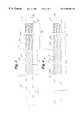
- FIG. 1is a plan view of a catheter in accordance with an exemplary embodiment of the present invention
- FIG. 2is a cross-sectional plan view of an elongate shaft in accordance with an exemplary embodiment of the present invention
- FIG. 3is a plan view of an assembly including an inner tubular member and a filament in accordance with an exemplary embodiment of the present invention, the filament being circumferentially disposed about the inner tubular member following a generally helical path and forming a plurality of turns comprising a support member;
- FIG. 4is a plan view of the assembly of FIG. 3, to which a second layer has been added to a portion of the support member to form a lattice;
- FIG. 5is a plan view of the assembly of FIG. 4, to which a third layer has been added to a portion of the support member;
- FIG. 6is a plan view of the assembly of FIG. 5, in which a plurality of portions forming an outer layer are circumferentially disposed over the support member and the inner tubular member.
- FIG. 1is a plan view of a catheter 10 in accordance with the present invention.
- Catheter 10includes an elongate shaft 12 having a distal end 14 , a proximal end 16 , an outer surface 18 , and a lumen 20 extending therethrough.
- Catheter 10further includes a hub 26 and a strain relief 28 disposed proximate proximal end 16 of elongate shaft 12 .
- Hub 26 and strain relief 28enable a physician to connect other devices to catheter 10 .
- Hub 26 and strain relief 28also provide a convenient place for a physician to apply longitudinal or rotational forces in order to manipulate catheter 10 .
- FIG. 2is a cross-sectional plan view of elongate shaft 12 of catheter 10 .
- Elongate shaft 12is comprised of an inner tubular member 30 having a first layer 32 , a second layer 34 , an outer surface 36 , and a distal end 38 .
- first layer 32 of inner tubular member 30is comprised of PTFE (polytetrafluoroethylene).
- PTFEpolytetrafluoroethylene
- second layer 34 of inner tubular member 30is comprised of polyether block amide (PEBA).
- inner tubular member 30may be comprised of a single layer or a plurality of layers without deviating from the spirit and scope of the present invention.
- materials suitable in some applicationsinclude polyolefins, polyamides, and polyimides.
- a support member 40overlies inner tubular member 30 and conforms to the surface thereof
- Support member 40has a first portion 42 , a second portion 44 , and a third portion 46 .
- First portion 42 , second portion 44 , and third portion 46each have a distal end 52 , 54 , and 56 respectively.
- first portion 42 , second portion 44 , and third portion 46each have a proximal end 62 , 64 , and 66 respectively.
- First portion 42 of support member 40is disposed proximate distal end 14 of inner tubular member 30 and is comprised of at least one filament 100 which is circumferentially disposed about inner tubular member 30 .
- At least one filament 100generally conforms to the shape of outer surface 36 of inner tubular member 30 and forms a plurality of turns 102 in a helical pattern.
- At least one filament 100follows a generally helical path. Also in the embodiment of FIG. 2, one filament 100 is illustrated. Those of skill in the art will appreciate, however, that two or more filaments could be circumferentially disposed about inner tubular member 30 without departing from the spirit or scope of the present invention. For example, two filaments 100 could be wound around inner tubular member 30 , each filament following a generally helical path, such that the two filaments create a double helix.
- a ring 70is circumferentially disposed about outer surface 36 of inner tubular member 30 proximate the distal end thereof.
- ring 70is comprised of a radiopaque material.
- ring 70produces a relatively bright image on a fluoroscopy screen during a medical procedure. This relatively bright image aids the user of catheter 10 in determining the location of distal end 14 of elongate shaft 12 .
- a number of radiopaque materialsare acceptable for use in fabricating ring 70 . Acceptable materials included gold, platnium, and a plastic material loaded with a radiopaque filler.
- a distal portion 104 of at least one filament 100is disposed between outer surface 36 of inner tubular member 30 and radiopaque ring 70 . Placing distal portion 104 of filament 100 in this position has the advantage of retaining distal portion 104 of filament 100 while the remainder of filament 100 is wound around inner tubular member 30 .
- Second portion 44 of support member 40is circumferentially disposed about inner tubular member 30 , with its distal end 54 proximate proximal end 62 of first portion 42 of support member 40 .
- Second portion 44 of support member 40is comprised of a first layer 82 , a second layer 84 , and a third layer 86 .
- Each layer 82 , 84 , and 86is comprised of a plurality of turns 92 , 94 , and 96 , respectively.
- Turns 92 , 94 , and 96are formed of filaments 112 , 114 , and 116 , respectively.
- filaments 100 , 112 , 114 , and 116are all coextensive.
- Third portion 46 of support member 40is comprised of a plurality of turns 122 formed by at least one filament 120 .
- filament 120is coextensive with both filaments 100 , 112 , 114 and 116 .
- Third portion 46 of support member 40is disposed with its distal end 56 proximate proximal end 64 of second portion 44 .
- elongate shaft 12includes a flare 22 disposed proximate proximal end 16 thereof.
- Hub 26may be formed over proximal end 16 of elongate shaft 12 as shown in FIG. 1 .
- hub 26is formed using an overmolding process.
- support member 40is formed of a single filament 200 .
- filament 200is comprised of filaments 100 , 112 , 114 , 116 , and 120 , all of which are coextensive.
- filament 200includes a distal end 202 and a proximal end 204 .
- distal end 202 of filament 200will protrude through the outer layer of catheter 10 since the distal portion of filament 200 is retained by ring 70 , as described above.
- proximal end 204 of filament 200will protrude from catheter 10 , since hub 26 is formed over proximal end 16 of elongate shaft 12 .
- FIG. 2is an enlarged, partial cross-section illustrating second portion 44 of support member 40 .
- second layer 84 of second portion 44 of support member 40overlays first layer 82 .
- third layer 86 of second portion 44 of support member 40overlays second layer 84 .
- an outer layer 190overlays both support member 40 and inner tubular member 30 .
- the material of outer layer 190fills in any interstitial spaces in support member 40 .
- outer layer 190is comprised of a distal portion 192 , a middle portion 194 , and a proximal portion 196 .
- distal portion 192 of outer layer 190has been fused to the distal end of middle portion 194 .
- proximal end of middle portion 194 of outer layer 190has been fused to the distal end of proximal portion 196 .
- distal portion 192 , middle portion 194 , and proximal portion 196combine to form an outer layer 190 which is substantially continuous.
- proximal portion 196 of outer layer 190has an outer diameter A
- distal portion 192has an outer diameter D
- middle portion 194 of outer layer 190includes a first outer diameter B substantially equal to outer diameter A of proximal portion 196 and a second outer diameter C substantially equal to outer diameter D of distal portion 192 .
- Middle portion 194also includes a taper 98 extending between outer diameter B and outer diameter C of middle portion 194 .
- distal end 54 of second portion 44 of support member 40is disposed proximate taper 98 of middle portion 194 of outer layer 190 .
- distal end 54 of second portion 44 of support member 40may be disposed proximal to taper 98 of middle portion 194 of outer layer 190 .
- outer diameter A of proximal portion 196 of outer layer 190is large enough to substantially cover layers 82 , 83 , and 84 of second portion 44 of support member 40 .
- outer diameter D of distal portion 192 of outer layer 190is large enough to substantially cover first portion 42 of support member 40 .
- outer diameter D of distal portion 192is smaller than outer diameter A of proximal portion 196 . It may be appreciated that the single layer construction of first portion 42 of support member 40 facilitates having an outer diameter D of distal portion 192 which is smaller than outer diameter A of proximal portion 96 .
- distal end 202 of filament 200is retained by ring 70 , and proximal end 204 of filament 200 is disposed within hub 26 of catheter 10 .
- diameters A and Ddo not need to be enlarged to prevent distal ends 202 and 204 from protruding out of catheter 10 .
- the plurality of turns 102 forming first portion 42 of support member 40are disposed at a first pitch 152 .
- the turns 82 , 84 , and 86 of second portion 44 of support member 40are disposed at a second pitch 154 different than first pitch 152 .
- turns 122 of third portion 46 of support member 40are disposed at a third pitch 156 .
- pitches 152 , 154 , and 156 of support member 40may be selected to impart desired performance characteristics upon catheter 10 .
- third pitch 156may be relatively coarse to so that it does not hinder the formation of flare 22 .
- distal end 52 of first portion 42 of support member 40is disposed proximate distal end 14 of elongate shaft 12 .
- An atraumatic tip 150is formed of inner tubular member 30 and outer layer 190 .
- atraumatic tip 150is disposed distally of distal portion 52 of first portion 42 of support member 40 .
- atraumatic tip 150has a level of flexibility which makes it unlikely to damage the blood vessels of a patient.
- filaments 100 , 112 , 114 , 116 , and 120 of support member 40are coextensive in a presently preferred embodiment.
- filaments 100 , 112 , 114 , 116 , and 120comprise metal wire.
- filaments 100 , 112 , 114 , 116 , and 120are comprised of stainless steel wire.
- filaments 100 , 112 , 114 , 116 , and 120may be comprised of other materials without deviating from the spirit or scope of the present invention.
- filaments 100 , 112 , 114 , 116 , and 120may be comprised of metallic or non-metallic materials. Examples of materials which may be suitable in some applications include: nickel titanium alloy, nylon, KEVLAR, and carbon fibers.
- outer layer 190is comprised of polyether block amide (PEBA).
- PEBApolyether block amide
- Polyether block amideis commercially available from Atochem Polymers of Birdsboro, Pa., under the trade name PEBAX.
- distal portion 192 , middle portion 194 , and proximal portion 196 of outer tubular layerare comprised of a PEBA polymer having durometers of about 35 , 63 , and 72 respectively.
- Outer layer 190may be comprised of other materials without departing from the spirit of scope of this invention.
- materials which may be suitable in some applicationsinclude polyethylene (PE), polypropylene (PP), polyvinylchloride (PVC), polyurethane, and polytetrafluoroethylene (PTFE).
- PEpolyethylene
- PPpolypropylene
- PVCpolyvinylchloride
- PTFEpolytetrafluoroethylene
- additives, loading agents, or fillersmay be added to the material of outer layer 190 without deviating from the spirit or scope of the present invention.
- These additional materialsmay include color pigments, radiopaque materials, lubricants, or fillers.
- FIG. 3is a plan view of an assembly including inner tubular member 30 and a filament 300 .
- a ring 70is circumferentially disposed about outer surface 36 of inner tubular member 30 proximate its distal end 38 .
- a distal portion 301 of filament 300is disposed between outer surface 36 of inner tubular member 30 and radiopaque ring 70 .
- First portion 42 of support member 40is disposed proximate distal end 38 of inner tubular member 30 and is comprised of at least one filament 300 .
- Filament 300is circumferentially disposed about inner tubular member 30 and generally conforms to the shape of outer surface 36 . In the embodiment of FIG. 3, filament 300 follows a generally helical path and forms a plurality of turns 302 .
- Turns 302 of first portion 42are disposed at a first pitch 152 and combine to form the first portion 42 of a support member 40 .
- turns 302are disposed at a first pitch 152 of between about 0.020 inches per turn and 0.002 inches per turn.
- turns 302are disposed at a first pitch 152 of about 0.006 inches per turn.
- filament 300extends beyond first portion 42 of support member 40 to form the first layer 82 of a second portion 44 of support member 40 .
- Filament 300is circumferentially disposed about inner tubular member 30 and follows a generally helical path, forming a plurality of turns 304 .
- Turns 304 of second portion 44are disposed at a second pitch 154 .
- turns 304are disposed at a second pitch 154 of between about 0.050 inches per turn and 0.005 inches per turn.
- turns 304are disposed at a second pitch 154 of about 0.018 inches per turn.
- first pitch 152is generally finer than second pitch 154 .
- first pitch 152 and second pitch 154are substantially equal.
- FIG. 4is a plan view of the assembly of FIG. 3, in which a second layer 84 has added to second portion 44 of support member 40 .
- Second layer 84is comprised of a plurality of turns 306 which overlay first layer 82 of second portion 44 of support member 40 .
- Turns 306are formed by filament 300 which is disposed along a generally helical path overlaying first layer 82 of second portion 44 of support member 40 .
- FIG. 5is a plan view of the assembly of FIG. 4, in which a third layer 86 has added to second portion 44 of support member 40 .
- Third layer 86is comprised of a plurality of turns 308 which overlay second layer 84 of second portion 44 of support member 40 .
- Turns 308are formed by filament 300 which is disposed along a generally helical path overlaying second layer 84 of second portion 44 of support member 40 .
- filament 300extends beyond second portion 44 of support member 40 to form a third portion 46 of support member 40 .
- Filament 300is circumferentially disposed about inner tubular member 30 and follows a generally helical path, forming a plurality of turns 310 .
- Turns 310 of third portion 46are disposed at a third pitch 156 .
- third pitch 156is generally more coarse than first pitch 152 and second pitch 154 .
- FIG. 6is a plan view of the assembly of FIG. 5, in which portions 192 , 194 , and 196 forming outer layer 190 of elongate shaft 12 are circumferentially disposed over support member 40 and inner tubular member 30 .
- a method in accordance with the present inventiontypically begins with the step of temporarily or permanently securing distal portion 192 of filament 300 to inner tubular member 30 proximate its distal end.
- distal portion 192 of filament 300is secured by ring 70 .
- ring 70is circumferentially disposed about inner tubular member 30 proximate its distal end 38
- distal portion 192 of filament 300is disposed between ring 70 and outer surface 36 of inner tubular member 30 .
- a distal end 350 of filament 300is tied off.
- a location for tying off distal end 350 of filament 300is provided as part of an apparatus for winding filament 300 .
- Filament 300may be wound around inner tubular member 30 following a generally helical path to form a plurality of turns.
- First portion 42 of support member 40is comprised of a plurality of turns 302 .
- turns 302 of first portion 42 of support member 40are wound at a first pitch 152 .
- filament 300is wound beyond first portion 42 to form first layer 82 of second portion 44 of support member 40 .
- turns 304 of second portion 44are wound at a second pitch 154 .
- first portion 42 and second portion 44may be wound at the same pitch without deviating from the spirit and scope of the present invention.
- the winding of filament 300proceeds in a proximal direction.
- the direction of winding travelis reversed so that filament 300 begins forming turns 306 which overlay turns 304 of first layer 82 .
- second layer 84 of second portion 44 of support member 40is formed.
- second layer 84is comprised of turns 306 formed from filament 300 .
- the winding of filament 300proceeds in a distal direction until the path of filament 300 reaches distal end 54 of second portion 44 of support member 40 . At this point, the direction of winding travel is reversed so that filament 300 begins forming turns 308 which overlay turns 306 of second layer 84 . In this manner, third layer 86 of second portion 44 of support member 40 is formed.
- Third portion 46 of support member 40may be formed by proceeding to wind filament 300 along a generally helical path in a proximal direction beyond proximal end 65 of second portion 44 of support member 40 . After the formation of third portion 46 is complete, filament 300 may be cut off at a desired location, to separate it from the spool it was dispensed from.
- outer layer 190 of elongate shaft 12The steps involved in forming outer layer 190 of elongate shaft 12 are best illustrated in FIG. 6 .
- proximal portion 196 , middle portion 194 , and distal portion 192 of outer layer 190are all slid over support member 40 and inner tubular member 30 .
- portions 192 , 194 , and 196are all circumferentially disposed over support member 40 and inner tubular member 30 , as shown in FIG. 6 .
- sleeve 360may then be placed over the assembly.
- sleeve 360is comprised of polytetrafluoroethylene (PTFE).
- PTFEpolytetrafluoroethylene
- PTFEis preferred because it provides a substantially non-stick surface.
- sleeve 360is comprised of PTFE shrink tubing. Suitable PTFE shrink tubing is commercially available Zeus Industries of Orangeburg, S.C., and Raychem Corporation of Menlo Park, Calif.
- sleeve 360After placing sleeve 360 in the desired position, heat may be applied to sleeve 360 causing it to shrink. After shrinking, sleeve 360 substantially conforms to the outer surfaces of proximal portion 196 , middle portion 194 , and distal portion 192 .
- a number of methodsmay be used to heat sleeve 360 , including convection heating, radiation heating, and heating by conduction.
- sleeve 360is heated by directing a flow of hot air from a hot air gun so that it impinges on sleeve 360 .
- Hot air guns suitable for this applicationare commercially available from Leister Elektro-Geratebau of Lucerne, Switzerland.
- sleeve 360serves to retain the position of proximal portion 196 , middle portion 194 , and distal portion 192 .
- Sleeve 360also applies radially constrictive pressure to the outer surfaces of proximal portion 196 , middle portion 194 , and distal portion 192 .
- the steps of overlaying sleeve 360 over the assembly and shrinking sleeve 360may be omitted without deviating from the spirit and scope of the present invention.
- Methods in accordance with the present inventionhave been envisioned which do not utilize sleeve 360 .
- Methods in accordance with the present inventionhave also been envisioned in which the assembly is heated during subsequent steps, and the step of applying heat to sleeve 360 is omitted.
- distal portion 192 , middle portion 194 , and proximal portion 196are heated to a temperature near their melting point, causing them all to fuse together forming outer layer 190 .
- the elevated temperaturealso causes outer layer 190 to be securely bonded to support member 40 and inner tubular member 30 .
- the material of outer layer 190fills in any interstitial spaces in support member 40 .
- a number of methodsmay be used to heat the assembly, including convection heating, radiation heating, and heating by conduction.
- An example of heating with radiant energyis directing infrared energy from an infrared heat source at the assembly. Infrared energy sources suitable for this process are commercially available from Research Incorporated of Minnetonka, Minn.
- a second example of heating with radiant energyis exposing the regions to be heated to radio frequency energy.
- heating with convectionincludes placing the assembly being heated in a temperature chamber.
- Temperature chambers suitable for this processare commercially available from Thermotron Corporation of New Holland, Mich.
- Suitable heated toolsmay be comprised of a number of materials including stainless steel. Electric heaters suitable for heating a heated tool are commercially available from Watlow Incorporated of St. Louis, Mo.
- the assemblymay be allowed to cool.
- the assemblymay be submersed in a relatively cool fluid.
- fluidswhich may be suitable for some applications include water and air.
- a temperature chamber with both heating and cooling capabilitiesis utilized. This temperature chamber is capable of producing an elevated temperature environment for heating and a low temperature environment for cooling. Temperature chambers with this capability are commercially available from Thermotron Corporation of New Holland, Mich. A flow of relatively cool air may also be directed at the assembly to speed cooling. Cold air generators suitable for this purpose are commercially available from ITW Vortec of Cincinnati, Ohio, and Exair Corporation of Cincinnati, Ohio.
- sleeve 360may be removed. This may be accomplished by scoring sleeve 360 with a cutting tool, and peeling it away from outer layer 190 .
- sleeve 360is comprised of polytetrafluoroethylene (PTFE). PTFE is preferred because it provides a substantially non-stick surface. This substantially non-stick surface aids in the removal of sleeve 360 from outer layer 190 .
- a mandrelis placed in lumen 20 of inner tubular member 30 . If a mandrel has been used, it may also be removed after the assembly has cooled. It should be understood that steps may be omitted from this process without deviating from the spirit or scope of the invention. For example, alternate methods have been envisioned, in which the use of sleeve 360 is not required.
Landscapes
- Health & Medical Sciences (AREA)
- Life Sciences & Earth Sciences (AREA)
- Biomedical Technology (AREA)
- Pulmonology (AREA)
- Engineering & Computer Science (AREA)
- Anesthesiology (AREA)
- Biophysics (AREA)
- Heart & Thoracic Surgery (AREA)
- Hematology (AREA)
- Animal Behavior & Ethology (AREA)
- General Health & Medical Sciences (AREA)
- Public Health (AREA)
- Veterinary Medicine (AREA)
- Materials For Medical Uses (AREA)
- Media Introduction/Drainage Providing Device (AREA)
Abstract
Description
Claims (21)
Priority Applications (7)
| Application Number | Priority Date | Filing Date | Title |
|---|---|---|---|
| US09/363,122US6508804B2 (en) | 1999-07-28 | 1999-07-28 | Catheter having continuous lattice and coil reinforcement |
| PCT/US2000/040380WO2001008738A1 (en) | 1999-07-28 | 2000-07-13 | Catheter having a continuous wire coil reinforcement |
| ES00960147TES2232492T3 (en) | 1999-07-28 | 2000-07-13 | CATHETER WITH REINFORCED WIRE COIL REINFORCEMENT. |
| DE60017752TDE60017752T2 (en) | 1999-07-28 | 2000-07-13 | CATHETER WITH A THREADED THREADED REINFORCEMENT |
| AT00960147TATE287746T1 (en) | 1999-07-28 | 2000-07-13 | CATHETER WITH A CONTINUOUS WRAPPED WIRE REINFORCEMENT |
| CA002380113ACA2380113C (en) | 1999-07-28 | 2000-07-13 | Catheter having a continuous wire coil reinforcement |
| EP00960147AEP1202769B1 (en) | 1999-07-28 | 2000-07-13 | Catheter having a continuous wire coil reinforcement |
Applications Claiming Priority (1)
| Application Number | Priority Date | Filing Date | Title |
|---|---|---|---|
| US09/363,122US6508804B2 (en) | 1999-07-28 | 1999-07-28 | Catheter having continuous lattice and coil reinforcement |
Publications (2)
| Publication Number | Publication Date |
|---|---|
| US20010041881A1 US20010041881A1 (en) | 2001-11-15 |
| US6508804B2true US6508804B2 (en) | 2003-01-21 |
Family
ID=23428897
Family Applications (1)
| Application Number | Title | Priority Date | Filing Date |
|---|---|---|---|
| US09/363,122Expired - LifetimeUS6508804B2 (en) | 1999-07-28 | 1999-07-28 | Catheter having continuous lattice and coil reinforcement |
Country Status (7)
| Country | Link |
|---|---|
| US (1) | US6508804B2 (en) |
| EP (1) | EP1202769B1 (en) |
| AT (1) | ATE287746T1 (en) |
| CA (1) | CA2380113C (en) |
| DE (1) | DE60017752T2 (en) |
| ES (1) | ES2232492T3 (en) |
| WO (1) | WO2001008738A1 (en) |
Cited By (142)
| Publication number | Priority date | Publication date | Assignee | Title |
|---|---|---|---|---|
| US20030093060A1 (en)* | 2001-11-09 | 2003-05-15 | Vadnais Technologies Corporation | Catheter assembly |
| US20030167051A1 (en)* | 2002-02-28 | 2003-09-04 | Pu Zhou | Intravascular catheter shaft |
| US20040175525A1 (en)* | 2002-02-28 | 2004-09-09 | Scimed Life Systems, Inc. | Catheter incorporating an improved polymer shaft |
| US20040220549A1 (en)* | 2003-04-14 | 2004-11-04 | Dittman Jay A. | Large diameter delivery catheter/sheath |
| US20040254544A1 (en)* | 2003-06-12 | 2004-12-16 | Russell Scott M. | Orifice device for delivering drugs at low fluid flow rates |
| US20040254563A1 (en)* | 2003-06-12 | 2004-12-16 | Russell Scott M. | Method for manufacturing an orifice mechanism capable of low fluid flow rates |
| US20040267241A1 (en)* | 2003-06-12 | 2004-12-30 | Russell Scott M. | Orifice device having multiple channels and multiple layers for drug delivery |
| US20050004557A1 (en)* | 2003-06-12 | 2005-01-06 | Russell Scott M. | Orifice device having multiple channels with varying flow rates for drug delivery |
| US20050043714A1 (en)* | 2003-08-20 | 2005-02-24 | Scimed Life Systems, Inc. | Medical device incorporating a polymer blend |
| US20050090802A1 (en)* | 2003-04-28 | 2005-04-28 | Connors John J.Iii | Flexible sheath with varying durometer |
| US20050177185A1 (en)* | 2004-02-05 | 2005-08-11 | Scimed Life Systems, Inc. | Counterwound coil for embolic protection sheath |
| US20050182475A1 (en)* | 2003-09-02 | 2005-08-18 | Jimmy Jen | Delivery system for a medical device |
| US20070005003A1 (en)* | 2003-12-31 | 2007-01-04 | Patterson Ryan C | Reinforced multi-lumen catheter |
| US7211076B2 (en) | 2003-06-12 | 2007-05-01 | Cordis Corporation | Medical device for fluid delivery having low fluid flow rate |
| US20070112371A1 (en)* | 2005-11-14 | 2007-05-17 | Medtronic Vascular, Inc. | Embolic protection filter having compact collapsed dimensions and method of making same |
| US20080103456A1 (en)* | 2006-10-30 | 2008-05-01 | Johnson Benjamin A | Infusion catheter |
| EP2067465A2 (en) | 2007-12-07 | 2009-06-10 | Gerald Moss | Reinforced enteral feeding catheter |
| US7771369B2 (en) | 2003-12-05 | 2010-08-10 | Boston Scientific Scimed, Inc. | Guide catheter with removable support |
| US20100256693A1 (en)* | 2009-04-07 | 2010-10-07 | Boston Scientific Neuromodulation Corporation | Insulator layers for leads of implantable electric stimulation systems and methods of making and using |
| US20110009932A1 (en)* | 2009-07-08 | 2011-01-13 | Boston Scientific Neuromodulation Corporation | Systems and methods of making and using support elements for elongated members of implantable electric stimulation systems |
| US20110160702A1 (en)* | 2006-05-12 | 2011-06-30 | Micrus Design Technology, Inc. | Double helix reinforced catheter |
| US20110238041A1 (en)* | 2010-03-24 | 2011-09-29 | Chestnut Medical Technologies, Inc. | Variable flexibility catheter |
| US8251976B2 (en) | 2003-08-20 | 2012-08-28 | Boston Scientific Scimed, Inc. | Medical device incorporating a polymer blend |
| US20140123463A1 (en)* | 2011-03-08 | 2014-05-08 | Abbott Cardiovascular Systems Inc. | Catheter with radiopaque coil |
| US8880185B2 (en) | 2010-06-11 | 2014-11-04 | Boston Scientific Scimed, Inc. | Renal denervation and stimulation employing wireless vascular energy transfer arrangement |
| US8939970B2 (en) | 2004-09-10 | 2015-01-27 | Vessix Vascular, Inc. | Tuned RF energy and electrical tissue characterization for selective treatment of target tissues |
| US8951251B2 (en) | 2011-11-08 | 2015-02-10 | Boston Scientific Scimed, Inc. | Ostial renal nerve ablation |
| US8968383B1 (en) | 2013-08-27 | 2015-03-03 | Covidien Lp | Delivery of medical devices |
| US8974451B2 (en) | 2010-10-25 | 2015-03-10 | Boston Scientific Scimed, Inc. | Renal nerve ablation using conductive fluid jet and RF energy |
| EP2851061A1 (en) | 2013-09-18 | 2015-03-25 | Gerald Moss | Catheter and method of making the same |
| US9023034B2 (en) | 2010-11-22 | 2015-05-05 | Boston Scientific Scimed, Inc. | Renal ablation electrode with force-activatable conduction apparatus |
| US9028472B2 (en) | 2011-12-23 | 2015-05-12 | Vessix Vascular, Inc. | Methods and apparatuses for remodeling tissue of or adjacent to a body passage |
| US9028485B2 (en) | 2010-11-15 | 2015-05-12 | Boston Scientific Scimed, Inc. | Self-expanding cooling electrode for renal nerve ablation |
| US9050106B2 (en) | 2011-12-29 | 2015-06-09 | Boston Scientific Scimed, Inc. | Off-wall electrode device and methods for nerve modulation |
| US9060761B2 (en) | 2010-11-18 | 2015-06-23 | Boston Scientific Scime, Inc. | Catheter-focused magnetic field induced renal nerve ablation |
| US9079000B2 (en) | 2011-10-18 | 2015-07-14 | Boston Scientific Scimed, Inc. | Integrated crossing balloon catheter |
| US9084609B2 (en) | 2010-07-30 | 2015-07-21 | Boston Scientific Scime, Inc. | Spiral balloon catheter for renal nerve ablation |
| US9089350B2 (en) | 2010-11-16 | 2015-07-28 | Boston Scientific Scimed, Inc. | Renal denervation catheter with RF electrode and integral contrast dye injection arrangement |
| USD737429S1 (en) | 2012-06-13 | 2015-08-25 | Vijay A. Doraiswamy | Medical tube with radio-opaque double helix indicia |
| US9119632B2 (en) | 2011-11-21 | 2015-09-01 | Boston Scientific Scimed, Inc. | Deflectable renal nerve ablation catheter |
| US9119600B2 (en) | 2011-11-15 | 2015-09-01 | Boston Scientific Scimed, Inc. | Device and methods for renal nerve modulation monitoring |
| US9125667B2 (en) | 2004-09-10 | 2015-09-08 | Vessix Vascular, Inc. | System for inducing desirable temperature effects on body tissue |
| US9125666B2 (en) | 2003-09-12 | 2015-09-08 | Vessix Vascular, Inc. | Selectable eccentric remodeling and/or ablation of atherosclerotic material |
| EP2926856A1 (en) | 2014-03-31 | 2015-10-07 | Gerald Moss | Multi-lumen catheter |
| US9155589B2 (en) | 2010-07-30 | 2015-10-13 | Boston Scientific Scimed, Inc. | Sequential activation RF electrode set for renal nerve ablation |
| US9162046B2 (en) | 2011-10-18 | 2015-10-20 | Boston Scientific Scimed, Inc. | Deflectable medical devices |
| US9174020B2 (en) | 2013-05-08 | 2015-11-03 | Embolx, Inc. | Device and methods for transvascular tumor embolization with integrated flow regulation |
| US9173696B2 (en) | 2012-09-17 | 2015-11-03 | Boston Scientific Scimed, Inc. | Self-positioning electrode system and method for renal nerve modulation |
| US9186210B2 (en) | 2011-10-10 | 2015-11-17 | Boston Scientific Scimed, Inc. | Medical devices including ablation electrodes |
| US9186209B2 (en) | 2011-07-22 | 2015-11-17 | Boston Scientific Scimed, Inc. | Nerve modulation system having helical guide |
| US9192790B2 (en) | 2010-04-14 | 2015-11-24 | Boston Scientific Scimed, Inc. | Focused ultrasonic renal denervation |
| US9192435B2 (en) | 2010-11-22 | 2015-11-24 | Boston Scientific Scimed, Inc. | Renal denervation catheter with cooled RF electrode |
| US9220561B2 (en) | 2011-01-19 | 2015-12-29 | Boston Scientific Scimed, Inc. | Guide-compatible large-electrode catheter for renal nerve ablation with reduced arterial injury |
| US9220558B2 (en) | 2010-10-27 | 2015-12-29 | Boston Scientific Scimed, Inc. | RF renal denervation catheter with multiple independent electrodes |
| US9265969B2 (en) | 2011-12-21 | 2016-02-23 | Cardiac Pacemakers, Inc. | Methods for modulating cell function |
| US9277955B2 (en) | 2010-04-09 | 2016-03-08 | Vessix Vascular, Inc. | Power generating and control apparatus for the treatment of tissue |
| US9289255B2 (en) | 2002-04-08 | 2016-03-22 | Medtronic Ardian Luxembourg S.A.R.L. | Methods and apparatus for renal neuromodulation |
| US9297845B2 (en) | 2013-03-15 | 2016-03-29 | Boston Scientific Scimed, Inc. | Medical devices and methods for treatment of hypertension that utilize impedance compensation |
| US20160101262A1 (en)* | 2014-10-09 | 2016-04-14 | Vascular Solutions, Inc. | Catheter |
| US9326751B2 (en) | 2010-11-17 | 2016-05-03 | Boston Scientific Scimed, Inc. | Catheter guidance of external energy for renal denervation |
| US9327100B2 (en) | 2008-11-14 | 2016-05-03 | Vessix Vascular, Inc. | Selective drug delivery in a lumen |
| US9358365B2 (en) | 2010-07-30 | 2016-06-07 | Boston Scientific Scimed, Inc. | Precision electrode movement control for renal nerve ablation |
| US9364284B2 (en) | 2011-10-12 | 2016-06-14 | Boston Scientific Scimed, Inc. | Method of making an off-wall spacer cage |
| US9408661B2 (en) | 2010-07-30 | 2016-08-09 | Patrick A. Haverkost | RF electrodes on multiple flexible wires for renal nerve ablation |
| US9420955B2 (en) | 2011-10-11 | 2016-08-23 | Boston Scientific Scimed, Inc. | Intravascular temperature monitoring system and method |
| US9433760B2 (en) | 2011-12-28 | 2016-09-06 | Boston Scientific Scimed, Inc. | Device and methods for nerve modulation using a novel ablation catheter with polymeric ablative elements |
| US9452017B2 (en) | 2012-05-11 | 2016-09-27 | Medtronic Ardian Luxembourg S.A.R.L. | Multi-electrode catheter assemblies for renal neuromodulation and associated systems and methods |
| US9463062B2 (en) | 2010-07-30 | 2016-10-11 | Boston Scientific Scimed, Inc. | Cooled conductive balloon RF catheter for renal nerve ablation |
| US9486355B2 (en) | 2005-05-03 | 2016-11-08 | Vessix Vascular, Inc. | Selective accumulation of energy with or without knowledge of tissue topography |
| US9550046B1 (en) | 2016-02-16 | 2017-01-24 | Embolx, Inc. | Balloon catheter and methods of fabrication and use |
| US9554848B2 (en) | 1999-04-05 | 2017-01-31 | Medtronic, Inc. | Ablation catheters and associated systems and methods |
| US9579030B2 (en) | 2011-07-20 | 2017-02-28 | Boston Scientific Scimed, Inc. | Percutaneous devices and methods to visualize, target and ablate nerves |
| JP2017042222A (en)* | 2015-08-24 | 2017-03-02 | 株式会社東海メディカルプロダクツ | catheter |
| US9636173B2 (en) | 2010-10-21 | 2017-05-02 | Medtronic Ardian Luxembourg S.A.R.L. | Methods for renal neuromodulation |
| US9649156B2 (en) | 2010-12-15 | 2017-05-16 | Boston Scientific Scimed, Inc. | Bipolar off-wall electrode device for renal nerve ablation |
| US9668811B2 (en) | 2010-11-16 | 2017-06-06 | Boston Scientific Scimed, Inc. | Minimally invasive access for renal nerve ablation |
| US9687166B2 (en) | 2013-10-14 | 2017-06-27 | Boston Scientific Scimed, Inc. | High resolution cardiac mapping electrode array catheter |
| US9693821B2 (en) | 2013-03-11 | 2017-07-04 | Boston Scientific Scimed, Inc. | Medical devices for modulating nerves |
| US9707036B2 (en) | 2013-06-25 | 2017-07-18 | Boston Scientific Scimed, Inc. | Devices and methods for nerve modulation using localized indifferent electrodes |
| US9707035B2 (en) | 2002-04-08 | 2017-07-18 | Medtronic Ardian Luxembourg S.A.R.L. | Methods for catheter-based renal neuromodulation |
| US9713730B2 (en) | 2004-09-10 | 2017-07-25 | Boston Scientific Scimed, Inc. | Apparatus and method for treatment of in-stent restenosis |
| US9770606B2 (en) | 2013-10-15 | 2017-09-26 | Boston Scientific Scimed, Inc. | Ultrasound ablation catheter with cooling infusion and centering basket |
| US9782186B2 (en) | 2013-08-27 | 2017-10-10 | Covidien Lp | Vascular intervention system |
| US9782561B2 (en) | 2014-10-09 | 2017-10-10 | Vacular Solutions, Inc. | Catheter tip |
| US9808300B2 (en) | 2006-05-02 | 2017-11-07 | Boston Scientific Scimed, Inc. | Control of arterial smooth muscle tone |
| US9808311B2 (en) | 2013-03-13 | 2017-11-07 | Boston Scientific Scimed, Inc. | Deflectable medical devices |
| US9827039B2 (en) | 2013-03-15 | 2017-11-28 | Boston Scientific Scimed, Inc. | Methods and apparatuses for remodeling tissue of or adjacent to a body passage |
| US9833283B2 (en) | 2013-07-01 | 2017-12-05 | Boston Scientific Scimed, Inc. | Medical devices for renal nerve ablation |
| US9844383B2 (en) | 2013-05-08 | 2017-12-19 | Embolx, Inc. | Devices and methods for low pressure tumor embolization |
| EP3260155A1 (en) | 2016-06-24 | 2017-12-27 | Asahi Intecc Co., Ltd. | Catheter |
| US9888961B2 (en) | 2013-03-15 | 2018-02-13 | Medtronic Ardian Luxembourg S.A.R.L. | Helical push wire electrode |
| US9895194B2 (en) | 2013-09-04 | 2018-02-20 | Boston Scientific Scimed, Inc. | Radio frequency (RF) balloon catheter having flushing and cooling capability |
| US9907609B2 (en) | 2014-02-04 | 2018-03-06 | Boston Scientific Scimed, Inc. | Alternative placement of thermal sensors on bipolar electrode |
| US9925001B2 (en) | 2013-07-19 | 2018-03-27 | Boston Scientific Scimed, Inc. | Spiral bipolar electrode renal denervation balloon |
| US9943365B2 (en) | 2013-06-21 | 2018-04-17 | Boston Scientific Scimed, Inc. | Renal denervation balloon catheter with ride along electrode support |
| US9956033B2 (en) | 2013-03-11 | 2018-05-01 | Boston Scientific Scimed, Inc. | Medical devices for modulating nerves |
| US9962223B2 (en) | 2013-10-15 | 2018-05-08 | Boston Scientific Scimed, Inc. | Medical device balloon |
| US9974607B2 (en) | 2006-10-18 | 2018-05-22 | Vessix Vascular, Inc. | Inducing desirable temperature effects on body tissue |
| US10022182B2 (en) | 2013-06-21 | 2018-07-17 | Boston Scientific Scimed, Inc. | Medical devices for renal nerve ablation having rotatable shafts |
| US10076382B2 (en) | 2010-10-25 | 2018-09-18 | Medtronic Ardian Luxembourg S.A.R.L. | Catheter apparatuses having multi-electrode arrays for renal neuromodulation and associated systems and methods |
| US10085799B2 (en) | 2011-10-11 | 2018-10-02 | Boston Scientific Scimed, Inc. | Off-wall electrode device and methods for nerve modulation |
| US10166069B2 (en) | 2014-01-27 | 2019-01-01 | Medtronic Ardian Luxembourg S.A.R.L. | Neuromodulation catheters having jacketed neuromodulation elements and related devices, systems, and methods |
| US10188829B2 (en) | 2012-10-22 | 2019-01-29 | Medtronic Ardian Luxembourg S.A.R.L. | Catheters with enhanced flexibility and associated devices, systems, and methods |
| WO2019055736A1 (en)* | 2017-09-15 | 2019-03-21 | Infraredx, Inc. | Imaging catheter |
| US10238834B2 (en) | 2017-08-25 | 2019-03-26 | Teleflex Innovations S.À.R.L. | Catheter |
| US10265122B2 (en) | 2013-03-15 | 2019-04-23 | Boston Scientific Scimed, Inc. | Nerve ablation devices and related methods of use |
| US10271898B2 (en) | 2013-10-25 | 2019-04-30 | Boston Scientific Scimed, Inc. | Embedded thermocouple in denervation flex circuit |
| US10321946B2 (en) | 2012-08-24 | 2019-06-18 | Boston Scientific Scimed, Inc. | Renal nerve modulation devices with weeping RF ablation balloons |
| US10342609B2 (en) | 2013-07-22 | 2019-07-09 | Boston Scientific Scimed, Inc. | Medical devices for renal nerve ablation |
| US10350382B1 (en) | 2018-06-08 | 2019-07-16 | Embolx, Inc. | High torque catheter and methods of manufacture |
| US10376396B2 (en) | 2017-01-19 | 2019-08-13 | Covidien Lp | Coupling units for medical device delivery systems |
| US10398464B2 (en) | 2012-09-21 | 2019-09-03 | Boston Scientific Scimed, Inc. | System for nerve modulation and innocuous thermal gradient nerve block |
| US10413357B2 (en) | 2013-07-11 | 2019-09-17 | Boston Scientific Scimed, Inc. | Medical device with stretchable electrode assemblies |
| US10512753B1 (en)* | 2018-12-07 | 2019-12-24 | John Nguyen | Composite catheter shafts and methods and apparatus for making the same |
| US10537452B2 (en) | 2012-02-23 | 2020-01-21 | Covidien Lp | Luminal stenting |
| US10548663B2 (en) | 2013-05-18 | 2020-02-04 | Medtronic Ardian Luxembourg S.A.R.L. | Neuromodulation catheters with shafts for enhanced flexibility and control and associated devices, systems, and methods |
| US10549127B2 (en) | 2012-09-21 | 2020-02-04 | Boston Scientific Scimed, Inc. | Self-cooling ultrasound ablation catheter |
| US10660703B2 (en) | 2012-05-08 | 2020-05-26 | Boston Scientific Scimed, Inc. | Renal nerve modulation devices |
| US10660698B2 (en) | 2013-07-11 | 2020-05-26 | Boston Scientific Scimed, Inc. | Devices and methods for nerve modulation |
| US10695124B2 (en) | 2013-07-22 | 2020-06-30 | Boston Scientific Scimed, Inc. | Renal nerve ablation catheter having twist balloon |
| US10722300B2 (en) | 2013-08-22 | 2020-07-28 | Boston Scientific Scimed, Inc. | Flexible circuit having improved adhesion to a renal nerve modulation balloon |
| US10736690B2 (en) | 2014-04-24 | 2020-08-11 | Medtronic Ardian Luxembourg S.A.R.L. | Neuromodulation catheters and associated systems and methods |
| US10786377B2 (en) | 2018-04-12 | 2020-09-29 | Covidien Lp | Medical device delivery |
| US10835305B2 (en) | 2012-10-10 | 2020-11-17 | Boston Scientific Scimed, Inc. | Renal nerve modulation devices and methods |
| US20210001098A1 (en)* | 2017-03-24 | 2021-01-07 | Asahi Intecc Co., Ltd. | Dilator |
| US10945786B2 (en) | 2013-10-18 | 2021-03-16 | Boston Scientific Scimed, Inc. | Balloon catheters with flexible conducting wires and related methods of use and manufacture |
| US10952790B2 (en) | 2013-09-13 | 2021-03-23 | Boston Scientific Scimed, Inc. | Ablation balloon with vapor deposited cover layer |
| US11000679B2 (en) | 2014-02-04 | 2021-05-11 | Boston Scientific Scimed, Inc. | Balloon protection and rewrapping devices and related methods of use |
| US11071637B2 (en) | 2018-04-12 | 2021-07-27 | Covidien Lp | Medical device delivery |
| US11123209B2 (en) | 2018-04-12 | 2021-09-21 | Covidien Lp | Medical device delivery |
| US11202671B2 (en) | 2014-01-06 | 2021-12-21 | Boston Scientific Scimed, Inc. | Tear resistant flex circuit assembly |
| US11213678B2 (en) | 2013-09-09 | 2022-01-04 | Medtronic Ardian Luxembourg S.A.R.L. | Method of manufacturing a medical device for neuromodulation |
| US11246654B2 (en) | 2013-10-14 | 2022-02-15 | Boston Scientific Scimed, Inc. | Flexible renal nerve ablation devices and related methods of use and manufacture |
| US11400254B2 (en) | 2017-10-27 | 2022-08-02 | Heraeus Medical Components Llc | Microcatheter and method |
| US11413174B2 (en) | 2019-06-26 | 2022-08-16 | Covidien Lp | Core assembly for medical device delivery systems |
| US11413176B2 (en) | 2018-04-12 | 2022-08-16 | Covidien Lp | Medical device delivery |
| US11464948B2 (en) | 2016-02-16 | 2022-10-11 | Embolx, Inc. | Balloon catheters and methods of manufacture and use |
| US11944558B2 (en) | 2021-08-05 | 2024-04-02 | Covidien Lp | Medical device delivery devices, systems, and methods |
| US12042413B2 (en) | 2021-04-07 | 2024-07-23 | Covidien Lp | Delivery of medical devices |
| US12109137B2 (en) | 2021-07-30 | 2024-10-08 | Covidien Lp | Medical device delivery |
| US12268824B2 (en) | 2018-07-27 | 2025-04-08 | Embolx, Inc. | Shaped catheter tip for tracking over a guidewire through turns in the vasculature |
| US12409298B2 (en) | 2019-08-20 | 2025-09-09 | Embolx, Inc. | Catheters and methods of manufacture and use |
Families Citing this family (38)
| Publication number | Priority date | Publication date | Assignee | Title |
|---|---|---|---|---|
| CA2378720A1 (en)* | 1999-07-23 | 2001-02-01 | Tfx Medical Extrusion Products | Catheter device having multi-lumen reinforced shaft and method of manufacture for same |
| US20050165366A1 (en)* | 2004-01-28 | 2005-07-28 | Brustad John R. | Medical tubing having variable characteristics and method of making same |
| US7445684B2 (en)* | 2003-12-11 | 2008-11-04 | Pursley Matt D | Catheter having fibrous reinforcement and method of making the same |
| US7601285B2 (en)* | 2003-12-31 | 2009-10-13 | Boston Scientific Scimed, Inc. | Medical device with varying physical properties and method for forming same |
| US7621904B2 (en)* | 2004-10-21 | 2009-11-24 | Boston Scientific Scimed, Inc. | Catheter with a pre-shaped distal tip |
| KR101122334B1 (en)* | 2004-11-05 | 2012-03-28 | 감브로 룬디아 아베 | Catheter for vascular access and method for manufacturing the same |
| JP4693091B2 (en)* | 2004-12-21 | 2011-06-01 | 朝日インテック株式会社 | Catheter and manufacturing method thereof |
| US9480589B2 (en)* | 2005-05-13 | 2016-11-01 | Boston Scientific Scimed, Inc. | Endoprosthesis delivery system |
| DE102006062187A1 (en)* | 2006-12-22 | 2008-06-26 | Biotronik Vi Patent Ag | Catheter tube member |
| US8114144B2 (en)* | 2007-10-17 | 2012-02-14 | Abbott Cardiovascular Systems Inc. | Rapid-exchange retractable sheath self-expanding delivery system with incompressible inner member and flexible distal assembly |
| USD640785S1 (en)* | 2010-11-08 | 2011-06-28 | Chiao-Hao Lee | Disposable drainage catheter |
| US20130184574A1 (en)* | 2011-07-25 | 2013-07-18 | Richard R. Newhauser, JR. | Devices and methods for transnasal irrigation or suctioning of the sinuses |
| US9192499B2 (en)* | 2013-03-11 | 2015-11-24 | Cook Medical Technologies Llc | Inner catheter for a self-expanding medical device delivery system with a closed coil wire |
| US9370639B2 (en)* | 2013-03-12 | 2016-06-21 | Cook Medical Technologies, LLC | Variable stiffness catheter |
| US20150100043A1 (en)* | 2013-10-09 | 2015-04-09 | Biosense Webster (Israel) Ltd. | Catheter with cross-braided proximal section and helical-coiled distal end |
| US10238406B2 (en) | 2013-10-21 | 2019-03-26 | Inari Medical, Inc. | Methods and apparatus for treating embolism |
| US10588642B2 (en) | 2014-05-15 | 2020-03-17 | Gauthier Biomedical, Inc. | Molding process and products formed thereby |
| JP7082052B2 (en) | 2015-09-03 | 2022-06-07 | ネプチューン メディカル インク. | A device for advancing the endoscope in the small intestine |
| CN113796927B (en) | 2015-10-23 | 2025-03-04 | 伊纳里医疗公司 | Intravascular treatment of vascular occlusion and related devices, systems and methods |
| EP3500151A4 (en) | 2016-08-18 | 2020-03-25 | Neptune Medical Inc. | DEVICE AND METHOD FOR IMPROVED VISUALIZATION OF THE SMALL BOWEL |
| FI3528717T3 (en) | 2016-10-24 | 2024-08-09 | Inari Medical Inc | Devices for treating vascular occlusion |
| JP7379321B2 (en) | 2017-07-20 | 2023-11-14 | ネプチューン メディカル インク. | Dynamically rigid overtube |
| WO2019050765A1 (en) | 2017-09-06 | 2019-03-14 | Inari Medical, Inc. | Hemostasis valves and methods of use |
| US11154314B2 (en) | 2018-01-26 | 2021-10-26 | Inari Medical, Inc. | Single insertion delivery system for treating embolism and associated systems and methods |
| US12059128B2 (en) | 2018-05-31 | 2024-08-13 | Neptune Medical Inc. | Device and method for enhanced visualization of the small intestine |
| CN112714658A (en) | 2018-07-19 | 2021-04-27 | 海王星医疗公司 | Dynamic rigidized composite medical structure |
| CA3114285A1 (en) | 2018-08-13 | 2020-02-20 | Inari Medical, Inc. | System for treating embolism and associated devices and methods |
| US11793392B2 (en) | 2019-04-17 | 2023-10-24 | Neptune Medical Inc. | External working channels |
| WO2020214221A1 (en) | 2019-04-17 | 2020-10-22 | Neptune Medical Inc. | Dynamically rigidizing composite medical structures |
| JP7638273B2 (en) | 2019-10-16 | 2025-03-03 | イナリ メディカル, インコーポレイテッド | Systems, devices and methods for treating vascular obstructions |
| CN114558231B (en)* | 2020-11-27 | 2024-02-20 | 微创神通医疗科技(上海)有限公司 | Conduit transition structure, conduit and choke conduit |
| KR20230133374A (en) | 2021-01-29 | 2023-09-19 | 넵튠 메디컬 인코포레이티드 | Device and method for preventing inadvertent movement of a dynamic stiffening device |
| EP4463083A1 (en) | 2022-01-11 | 2024-11-20 | Inari Medical, Inc. | Devices for removing clot material from intravascularly implanted devices, and associated systems and methods |
| US20250135159A1 (en)* | 2022-02-08 | 2025-05-01 | Neptune Medical Inc. | Dynamically rigidizing composite medical structures |
| CN114642816A (en)* | 2022-03-23 | 2022-06-21 | 环心医疗科技(苏州)有限公司 | Novel medical catheter |
| KR20250003955A (en) | 2022-04-27 | 2025-01-07 | 넵튠 메디컬 인코포레이티드 | Sanitary outer covering for endoscope |
| EP4583954A2 (en)* | 2022-09-09 | 2025-07-16 | Inari Medical, Inc. | Catheters having multiple coil layers, and associated systems and methods |
| US12330292B2 (en) | 2023-09-28 | 2025-06-17 | Neptune Medical Inc. | Telescoping robot |
Citations (58)
| Publication number | Priority date | Publication date | Assignee | Title |
|---|---|---|---|---|
| US4279252A (en) | 1979-08-24 | 1981-07-21 | Martin Michael T | X-ray scaling catheter |
| US4323071A (en) | 1978-04-24 | 1982-04-06 | Advanced Catheter Systems, Inc. | Vascular guiding catheter assembly and vascular dilating catheter assembly and a combination thereof and methods of making the same |
| US4425919A (en) | 1981-07-27 | 1984-01-17 | Raychem Corporation | Torque transmitting catheter apparatus |
| US4444186A (en) | 1981-06-15 | 1984-04-24 | Datascope Corporation | Envelope wrapping system for intra-aortic balloon |
| US4516972A (en) | 1982-01-28 | 1985-05-14 | Advanced Cardiovascular Systems, Inc. | Guiding catheter and method of manufacture |
| US4563181A (en) | 1983-02-18 | 1986-01-07 | Mallinckrodt, Inc. | Fused flexible tip catheter |
| US4571240A (en) | 1983-08-12 | 1986-02-18 | Advanced Cardiovascular Systems, Inc. | Catheter having encapsulated tip marker |
| US4636346A (en) | 1984-03-08 | 1987-01-13 | Cordis Corporation | Preparing guiding catheter |
| US4739768A (en) | 1986-06-02 | 1988-04-26 | Target Therapeutics | Catheter for guide-wire tracking |
| US4817613A (en) | 1987-07-13 | 1989-04-04 | Devices For Vascular Intervention, Inc. | Guiding catheter |
| US4863442A (en) | 1987-08-14 | 1989-09-05 | C. R. Bard, Inc. | Soft tip catheter |
| US4886506A (en) | 1986-12-23 | 1989-12-12 | Baxter Travenol Laboratories, Inc. | Soft tip catheter |
| US4898591A (en) | 1988-08-09 | 1990-02-06 | Mallinckrodt, Inc. | Nylon-PEBA copolymer catheter |
| US4925710A (en) | 1988-03-31 | 1990-05-15 | Buck Thomas F | Ultrathin-wall fluoropolymer tube with removable fluoropolymer core |
| US4990143A (en) | 1990-04-09 | 1991-02-05 | Sheridan Catheter Corporation | Reinforced medico-surgical tubes |
| US5017259A (en) | 1988-10-13 | 1991-05-21 | Terumo Kabushiki Kaisha | Preparation of catheter including bonding and then thermoforming |
| US5019057A (en) | 1989-10-23 | 1991-05-28 | Cordis Corporation | Catheter having reinforcing strands |
| US5037404A (en) | 1988-11-14 | 1991-08-06 | Cordis Corporation | Catheter having sections of variable torsion characteristics |
| US5057092A (en) | 1990-04-04 | 1991-10-15 | Webster Wilton W Jr | Braided catheter with low modulus warp |
| US5078702A (en) | 1988-03-25 | 1992-01-07 | Baxter International Inc. | Soft tip catheters |
| US5103543A (en) | 1989-03-02 | 1992-04-14 | The Microspring Company, Inc. | Method of making a torque transmitter |
| US5176660A (en) | 1989-10-23 | 1993-01-05 | Cordis Corporation | Catheter having reinforcing strands |
| US5221270A (en) | 1991-06-28 | 1993-06-22 | Cook Incorporated | Soft tip guiding catheter |
| US5234416A (en) | 1991-06-06 | 1993-08-10 | Advanced Cardiovascular Systems, Inc. | Intravascular catheter with a nontraumatic distal tip |
| US5251640A (en) | 1992-03-31 | 1993-10-12 | Cook, Incorporated | Composite wire guide shaft |
| US5254107A (en) | 1991-03-06 | 1993-10-19 | Cordis Corporation | Catheter having extended braid reinforced transitional tip |
| US5279596A (en) | 1990-07-27 | 1994-01-18 | Cordis Corporation | Intravascular catheter with kink resistant tip |
| US5295978A (en) | 1990-12-28 | 1994-03-22 | Union Carbide Chemicals & Plastics Technology Corporation | Biocompatible hydrophilic complexes and process for preparation and use |
| US5300048A (en) | 1993-05-12 | 1994-04-05 | Sabin Corporation | Flexible, highly radiopaque plastic material catheter |
| US5312356A (en) | 1989-05-22 | 1994-05-17 | Target Therapeutics | Catheter with low-friction distal segment |
| US5334166A (en) | 1991-10-04 | 1994-08-02 | Aubrey Palestrant | Apparatus and method for wetting hydrophilic-coated guide wires and catheters |
| US5399164A (en) | 1992-11-02 | 1995-03-21 | Catheter Imaging Systems | Catheter having a multiple durometer |
| US5441489A (en) | 1989-04-13 | 1995-08-15 | Mitsubishi Cable Industries, Ltd. | Catheter with body temperature glass transition region |
| US5445624A (en) | 1994-01-21 | 1995-08-29 | Exonix Research Corporation | Catheter with progressively compliant tip |
| US5454795A (en) | 1994-06-27 | 1995-10-03 | Target Therapeutics, Inc. | Kink-free spiral-wound catheter |
| US5478330A (en) | 1992-12-01 | 1995-12-26 | Cardiac Pathways Corporation | Steerable catheter with adjustable bend location and/or radius and method |
| US5496292A (en) | 1991-05-03 | 1996-03-05 | Burnham; Warren | Catheter with irregular inner and/or outer surfaces to reduce travelling friction |
| US5538513A (en) | 1992-10-23 | 1996-07-23 | Terumo Kabushiki Kaisha | Catheter tube having a filamentous reinforcing layer |
| US5554139A (en) | 1993-12-24 | 1996-09-10 | Terumo Kabushiki Kaisha | Catheter |
| US5569220A (en) | 1991-01-24 | 1996-10-29 | Cordis Webster, Inc. | Cardiovascular catheter having high torsional stiffness |
| US5599326A (en) | 1994-12-20 | 1997-02-04 | Target Therapeutics, Inc. | Catheter with multi-layer section |
| US5658264A (en) | 1994-11-10 | 1997-08-19 | Target Therapeutics, Inc. | High performance spiral-wound catheter |
| US5662622A (en) | 1995-04-04 | 1997-09-02 | Cordis Corporation | Intravascular catheter |
| US5676659A (en) | 1993-11-12 | 1997-10-14 | Medtronic, Inc. | Small diameter, high torque catheter |
| US5702373A (en) | 1995-08-31 | 1997-12-30 | Target Therapeutics, Inc. | Composite super-elastic alloy braid reinforced catheter |
| US5755704A (en) | 1996-10-29 | 1998-05-26 | Medtronic, Inc. | Thinwall guide catheter |
| US5769830A (en) | 1991-06-28 | 1998-06-23 | Cook Incorporated | Soft tip guiding catheter |
| US5782811A (en) | 1996-05-30 | 1998-07-21 | Target Therapeutics, Inc. | Kink-resistant braided catheter with distal side holes |
| US5785685A (en)* | 1994-09-16 | 1998-07-28 | Scimed Life Systems, Inc. | Balloon catheter with improved pressure source |
| US5792124A (en)* | 1995-01-04 | 1998-08-11 | Medtronic, Inc. | Reinforced catheter which gets softer towards the distal tip |
| US5836925A (en) | 1996-04-03 | 1998-11-17 | Soltesz; Peter P. | Catheter with variable flexibility properties and method of manufacture |
| WO1998056448A1 (en) | 1997-06-10 | 1998-12-17 | Target Therapeutics, Inc. | Optimized high performance multiple coil spiral-wound vascular catheter |
| US5851203A (en) | 1993-09-22 | 1998-12-22 | Cordis Corporation | Neuro-microcatheter |
| US5860963A (en) | 1993-12-10 | 1999-01-19 | Schneider (Usa) Inc | Guiding catheter |
| US5897567A (en)* | 1993-04-29 | 1999-04-27 | Scimed Life Systems, Inc. | Expandable intravascular occlusion material removal devices and methods of use |
| US5906605A (en) | 1997-01-10 | 1999-05-25 | Cardiac Pathways Corporation | Torquable guiding catheter for basket deployment and method |
| US5957842A (en)* | 1994-01-27 | 1999-09-28 | Cardima, Inc. | High resolution intravascular signal detection |
| US5960796A (en)* | 1993-01-29 | 1999-10-05 | Cardima, Inc. | Intravascular method and device for occluding a body lumen |
- 1999
- 1999-07-28USUS09/363,122patent/US6508804B2/ennot_activeExpired - Lifetime
- 2000
- 2000-07-13ESES00960147Tpatent/ES2232492T3/ennot_activeExpired - Lifetime
- 2000-07-13CACA002380113Apatent/CA2380113C/ennot_activeExpired - Lifetime
- 2000-07-13WOPCT/US2000/040380patent/WO2001008738A1/enactiveIP Right Grant
- 2000-07-13ATAT00960147Tpatent/ATE287746T1/ennot_activeIP Right Cessation
- 2000-07-13DEDE60017752Tpatent/DE60017752T2/ennot_activeExpired - Lifetime
- 2000-07-13EPEP00960147Apatent/EP1202769B1/ennot_activeExpired - Lifetime
Patent Citations (69)
| Publication number | Priority date | Publication date | Assignee | Title |
|---|---|---|---|---|
| US4323071B1 (en) | 1978-04-24 | 1990-05-29 | Advanced Cardiovascular System | |
| US4323071A (en) | 1978-04-24 | 1982-04-06 | Advanced Catheter Systems, Inc. | Vascular guiding catheter assembly and vascular dilating catheter assembly and a combination thereof and methods of making the same |
| US4279252A (en) | 1979-08-24 | 1981-07-21 | Martin Michael T | X-ray scaling catheter |
| US4444186A (en) | 1981-06-15 | 1984-04-24 | Datascope Corporation | Envelope wrapping system for intra-aortic balloon |
| US4425919A (en) | 1981-07-27 | 1984-01-17 | Raychem Corporation | Torque transmitting catheter apparatus |
| US4516972A (en) | 1982-01-28 | 1985-05-14 | Advanced Cardiovascular Systems, Inc. | Guiding catheter and method of manufacture |
| US4563181A (en) | 1983-02-18 | 1986-01-07 | Mallinckrodt, Inc. | Fused flexible tip catheter |
| US4571240A (en) | 1983-08-12 | 1986-02-18 | Advanced Cardiovascular Systems, Inc. | Catheter having encapsulated tip marker |
| US4636346A (en) | 1984-03-08 | 1987-01-13 | Cordis Corporation | Preparing guiding catheter |
| US4739768A (en) | 1986-06-02 | 1988-04-26 | Target Therapeutics | Catheter for guide-wire tracking |
| US4739768B2 (en) | 1986-06-02 | 1995-10-24 | Target Therapeutics Inc | Catheter for guide-wire tracking |
| US4739768B1 (en) | 1986-06-02 | 1994-11-15 | Target Therapeutics Inc | Catheter for guide-wire tracking |
| US4886506A (en) | 1986-12-23 | 1989-12-12 | Baxter Travenol Laboratories, Inc. | Soft tip catheter |
| US4817613A (en) | 1987-07-13 | 1989-04-04 | Devices For Vascular Intervention, Inc. | Guiding catheter |
| US4863442A (en) | 1987-08-14 | 1989-09-05 | C. R. Bard, Inc. | Soft tip catheter |
| US5078702A (en) | 1988-03-25 | 1992-01-07 | Baxter International Inc. | Soft tip catheters |
| US4925710A (en) | 1988-03-31 | 1990-05-15 | Buck Thomas F | Ultrathin-wall fluoropolymer tube with removable fluoropolymer core |
| US4898591A (en) | 1988-08-09 | 1990-02-06 | Mallinckrodt, Inc. | Nylon-PEBA copolymer catheter |
| US5017259A (en) | 1988-10-13 | 1991-05-21 | Terumo Kabushiki Kaisha | Preparation of catheter including bonding and then thermoforming |
| US5037404A (en) | 1988-11-14 | 1991-08-06 | Cordis Corporation | Catheter having sections of variable torsion characteristics |
| US5103543A (en) | 1989-03-02 | 1992-04-14 | The Microspring Company, Inc. | Method of making a torque transmitter |
| US5441489A (en) | 1989-04-13 | 1995-08-15 | Mitsubishi Cable Industries, Ltd. | Catheter with body temperature glass transition region |
| US5312356A (en) | 1989-05-22 | 1994-05-17 | Target Therapeutics | Catheter with low-friction distal segment |
| US5176660A (en) | 1989-10-23 | 1993-01-05 | Cordis Corporation | Catheter having reinforcing strands |
| US5019057A (en) | 1989-10-23 | 1991-05-28 | Cordis Corporation | Catheter having reinforcing strands |
| US5057092A (en) | 1990-04-04 | 1991-10-15 | Webster Wilton W Jr | Braided catheter with low modulus warp |
| US4990143A (en) | 1990-04-09 | 1991-02-05 | Sheridan Catheter Corporation | Reinforced medico-surgical tubes |
| US5279596A (en) | 1990-07-27 | 1994-01-18 | Cordis Corporation | Intravascular catheter with kink resistant tip |
| US5295978A (en) | 1990-12-28 | 1994-03-22 | Union Carbide Chemicals & Plastics Technology Corporation | Biocompatible hydrophilic complexes and process for preparation and use |
| US5569220A (en) | 1991-01-24 | 1996-10-29 | Cordis Webster, Inc. | Cardiovascular catheter having high torsional stiffness |
| US5254107A (en) | 1991-03-06 | 1993-10-19 | Cordis Corporation | Catheter having extended braid reinforced transitional tip |
| US5496292A (en) | 1991-05-03 | 1996-03-05 | Burnham; Warren | Catheter with irregular inner and/or outer surfaces to reduce travelling friction |
| US5234416A (en) | 1991-06-06 | 1993-08-10 | Advanced Cardiovascular Systems, Inc. | Intravascular catheter with a nontraumatic distal tip |
| US5769830A (en) | 1991-06-28 | 1998-06-23 | Cook Incorporated | Soft tip guiding catheter |
| US5221270A (en) | 1991-06-28 | 1993-06-22 | Cook Incorporated | Soft tip guiding catheter |
| US5334166A (en) | 1991-10-04 | 1994-08-02 | Aubrey Palestrant | Apparatus and method for wetting hydrophilic-coated guide wires and catheters |
| US5251640A (en) | 1992-03-31 | 1993-10-12 | Cook, Incorporated | Composite wire guide shaft |
| US5538513A (en) | 1992-10-23 | 1996-07-23 | Terumo Kabushiki Kaisha | Catheter tube having a filamentous reinforcing layer |
| US5399164A (en) | 1992-11-02 | 1995-03-21 | Catheter Imaging Systems | Catheter having a multiple durometer |
| US5542924A (en) | 1992-11-02 | 1996-08-06 | Catheter Imaging Systems | Method of forming a catheter having a multiple durometer |
| US5478330A (en) | 1992-12-01 | 1995-12-26 | Cardiac Pathways Corporation | Steerable catheter with adjustable bend location and/or radius and method |
| US5960796A (en)* | 1993-01-29 | 1999-10-05 | Cardima, Inc. | Intravascular method and device for occluding a body lumen |
| US5897567A (en)* | 1993-04-29 | 1999-04-27 | Scimed Life Systems, Inc. | Expandable intravascular occlusion material removal devices and methods of use |
| US5300048A (en) | 1993-05-12 | 1994-04-05 | Sabin Corporation | Flexible, highly radiopaque plastic material catheter |
| US5851203A (en) | 1993-09-22 | 1998-12-22 | Cordis Corporation | Neuro-microcatheter |
| US5676659A (en) | 1993-11-12 | 1997-10-14 | Medtronic, Inc. | Small diameter, high torque catheter |
| US5860963A (en) | 1993-12-10 | 1999-01-19 | Schneider (Usa) Inc | Guiding catheter |
| US5554139A (en) | 1993-12-24 | 1996-09-10 | Terumo Kabushiki Kaisha | Catheter |
| US5445624A (en) | 1994-01-21 | 1995-08-29 | Exonix Research Corporation | Catheter with progressively compliant tip |
| US5957842A (en)* | 1994-01-27 | 1999-09-28 | Cardima, Inc. | High resolution intravascular signal detection |
| US5695483A (en) | 1994-06-27 | 1997-12-09 | Target Therapeutics Inc. | Kink-free spiral-wound catheter |
| US5454795A (en) | 1994-06-27 | 1995-10-03 | Target Therapeutics, Inc. | Kink-free spiral-wound catheter |
| US5785685A (en)* | 1994-09-16 | 1998-07-28 | Scimed Life Systems, Inc. | Balloon catheter with improved pressure source |
| US5853400A (en) | 1994-11-10 | 1998-12-29 | Target Therapeutics, Inc. | High performance spiral-wound catheter |
| US5658264A (en) | 1994-11-10 | 1997-08-19 | Target Therapeutics, Inc. | High performance spiral-wound catheter |
| US5795341A (en) | 1994-11-10 | 1998-08-18 | Target Therapeutics, Inc. | High performance spiral-wound catheter |
| US5599326A (en) | 1994-12-20 | 1997-02-04 | Target Therapeutics, Inc. | Catheter with multi-layer section |
| US5792124A (en)* | 1995-01-04 | 1998-08-11 | Medtronic, Inc. | Reinforced catheter which gets softer towards the distal tip |
| US5811043A (en)* | 1995-01-04 | 1998-09-22 | Medtronic, Inc. | Method of soft tip forming |
| US5662622A (en) | 1995-04-04 | 1997-09-02 | Cordis Corporation | Intravascular catheter |
| US5733400A (en) | 1995-04-04 | 1998-03-31 | Cordis Corporation | Intravascular catheter |
| US5711909A (en) | 1995-04-04 | 1998-01-27 | Cordis Corporation | Intravascular catheter and method of manufacturing |
| US5702373A (en) | 1995-08-31 | 1997-12-30 | Target Therapeutics, Inc. | Composite super-elastic alloy braid reinforced catheter |
| US5836925A (en) | 1996-04-03 | 1998-11-17 | Soltesz; Peter P. | Catheter with variable flexibility properties and method of manufacture |
| US5782811A (en) | 1996-05-30 | 1998-07-21 | Target Therapeutics, Inc. | Kink-resistant braided catheter with distal side holes |
| US5755704A (en) | 1996-10-29 | 1998-05-26 | Medtronic, Inc. | Thinwall guide catheter |
| US5906605A (en) | 1997-01-10 | 1999-05-25 | Cardiac Pathways Corporation | Torquable guiding catheter for basket deployment and method |
| WO1998056448A1 (en) | 1997-06-10 | 1998-12-17 | Target Therapeutics, Inc. | Optimized high performance multiple coil spiral-wound vascular catheter |
| US5951539A (en)* | 1997-06-10 | 1999-09-14 | Target Therpeutics, Inc. | Optimized high performance multiple coil spiral-wound vascular catheter |
Cited By (221)
| Publication number | Priority date | Publication date | Assignee | Title |
|---|---|---|---|---|
| US9554848B2 (en) | 1999-04-05 | 2017-01-31 | Medtronic, Inc. | Ablation catheters and associated systems and methods |
| US20030093060A1 (en)* | 2001-11-09 | 2003-05-15 | Vadnais Technologies Corporation | Catheter assembly |
| US20030167051A1 (en)* | 2002-02-28 | 2003-09-04 | Pu Zhou | Intravascular catheter shaft |
| US20040175525A1 (en)* | 2002-02-28 | 2004-09-09 | Scimed Life Systems, Inc. | Catheter incorporating an improved polymer shaft |
| US9289255B2 (en) | 2002-04-08 | 2016-03-22 | Medtronic Ardian Luxembourg S.A.R.L. | Methods and apparatus for renal neuromodulation |
| US9707035B2 (en) | 2002-04-08 | 2017-07-18 | Medtronic Ardian Luxembourg S.A.R.L. | Methods for catheter-based renal neuromodulation |
| US9675413B2 (en) | 2002-04-08 | 2017-06-13 | Medtronic Ardian Luxembourg S.A.R.L. | Methods and apparatus for renal neuromodulation |
| US20040220549A1 (en)* | 2003-04-14 | 2004-11-04 | Dittman Jay A. | Large diameter delivery catheter/sheath |
| US20100163159A1 (en)* | 2003-04-14 | 2010-07-01 | Cook Incorporated | Large diameter delivery catheter/sheath |
| US7704245B2 (en) | 2003-04-14 | 2010-04-27 | Cook Incorporated | Large diameter delivery catheter/sheath |
| US7968038B2 (en) | 2003-04-14 | 2011-06-28 | Cook Medical Technologies Llc | Large diameter delivery catheter/sheath |
| US20050090802A1 (en)* | 2003-04-28 | 2005-04-28 | Connors John J.Iii | Flexible sheath with varying durometer |
| US11000670B2 (en) | 2003-04-28 | 2021-05-11 | Cook Medical Technologies Llc | Flexible sheath with varying durometer |
| US7108762B2 (en) | 2003-06-12 | 2006-09-19 | Cordis Corporation | Method for manufacturing an orifice mechanism capable of low fluid flow rates |
| US7211076B2 (en) | 2003-06-12 | 2007-05-01 | Cordis Corporation | Medical device for fluid delivery having low fluid flow rate |
| US8109922B2 (en)* | 2003-06-12 | 2012-02-07 | Cordis Corporation | Orifice device having multiple channels and multiple layers for drug delivery |
| US8491571B2 (en) | 2003-06-12 | 2013-07-23 | Cordis Corporation | Orifice device having multiple channels with varying flow rates for drug delivery |
| US20040254563A1 (en)* | 2003-06-12 | 2004-12-16 | Russell Scott M. | Method for manufacturing an orifice mechanism capable of low fluid flow rates |
| US20040267241A1 (en)* | 2003-06-12 | 2004-12-30 | Russell Scott M. | Orifice device having multiple channels and multiple layers for drug delivery |
| US20050004557A1 (en)* | 2003-06-12 | 2005-01-06 | Russell Scott M. | Orifice device having multiple channels with varying flow rates for drug delivery |
| US20040254544A1 (en)* | 2003-06-12 | 2004-12-16 | Russell Scott M. | Orifice device for delivering drugs at low fluid flow rates |
| US7678103B2 (en) | 2003-06-12 | 2010-03-16 | Cordis Corporation | Orifice device for delivering drugs at low fluid flow rates |
| US7615043B2 (en) | 2003-08-20 | 2009-11-10 | Boston Scientific Scimed, Inc. | Medical device incorporating a polymer blend |
| US8251976B2 (en) | 2003-08-20 | 2012-08-28 | Boston Scientific Scimed, Inc. | Medical device incorporating a polymer blend |
| US20050043714A1 (en)* | 2003-08-20 | 2005-02-24 | Scimed Life Systems, Inc. | Medical device incorporating a polymer blend |
| US8486128B2 (en) | 2003-09-02 | 2013-07-16 | Abbott Laboratories | Delivery system for a medical device |
| US20050182475A1 (en)* | 2003-09-02 | 2005-08-18 | Jimmy Jen | Delivery system for a medical device |
| US10188457B2 (en) | 2003-09-12 | 2019-01-29 | Vessix Vascular, Inc. | Selectable eccentric remodeling and/or ablation |
| US9510901B2 (en) | 2003-09-12 | 2016-12-06 | Vessix Vascular, Inc. | Selectable eccentric remodeling and/or ablation |
| US9125666B2 (en) | 2003-09-12 | 2015-09-08 | Vessix Vascular, Inc. | Selectable eccentric remodeling and/or ablation of atherosclerotic material |
| US20100249754A1 (en)* | 2003-12-05 | 2010-09-30 | Boston Scientific Scimed, Inc. | Guide Catheter With Removable Support |
| US7771369B2 (en) | 2003-12-05 | 2010-08-10 | Boston Scientific Scimed, Inc. | Guide catheter with removable support |
| US8277438B2 (en) | 2003-12-05 | 2012-10-02 | Boston Scientific Scimed, Inc. | Guide catheter with removable support |
| US8430988B2 (en) | 2003-12-31 | 2013-04-30 | C. R. Bard, Inc. | Reinforced multi-lumen catheter |
| US7972465B2 (en) | 2003-12-31 | 2011-07-05 | C. R. Bard, Inc. | Reinforced multi-lumen catheter |
| US20100132879A1 (en)* | 2003-12-31 | 2010-06-03 | C.R. Bard, Inc. | Reinforced multi-lumen catheter |
| US20110192008A1 (en)* | 2003-12-31 | 2011-08-11 | C. R. Bard, Inc. | Reinforced multi-lumen catheter |
| US20070005003A1 (en)* | 2003-12-31 | 2007-01-04 | Patterson Ryan C | Reinforced multi-lumen catheter |
| US20050177185A1 (en)* | 2004-02-05 | 2005-08-11 | Scimed Life Systems, Inc. | Counterwound coil for embolic protection sheath |
| US8939970B2 (en) | 2004-09-10 | 2015-01-27 | Vessix Vascular, Inc. | Tuned RF energy and electrical tissue characterization for selective treatment of target tissues |
| US9125667B2 (en) | 2004-09-10 | 2015-09-08 | Vessix Vascular, Inc. | System for inducing desirable temperature effects on body tissue |
| US9713730B2 (en) | 2004-09-10 | 2017-07-25 | Boston Scientific Scimed, Inc. | Apparatus and method for treatment of in-stent restenosis |
| US9486355B2 (en) | 2005-05-03 | 2016-11-08 | Vessix Vascular, Inc. | Selective accumulation of energy with or without knowledge of tissue topography |
| US20070112371A1 (en)* | 2005-11-14 | 2007-05-17 | Medtronic Vascular, Inc. | Embolic protection filter having compact collapsed dimensions and method of making same |
| US9808300B2 (en) | 2006-05-02 | 2017-11-07 | Boston Scientific Scimed, Inc. | Control of arterial smooth muscle tone |
| US8366699B2 (en)* | 2006-05-12 | 2013-02-05 | Micrus Design Technology, Inc. | Double helix reinforced catheter |
| US20110160702A1 (en)* | 2006-05-12 | 2011-06-30 | Micrus Design Technology, Inc. | Double helix reinforced catheter |
| US8702680B2 (en) | 2006-05-12 | 2014-04-22 | DePuy Synthes Products, LLC | Double helix reinforced catheter |
| US9974607B2 (en) | 2006-10-18 | 2018-05-22 | Vessix Vascular, Inc. | Inducing desirable temperature effects on body tissue |
| US12161392B2 (en) | 2006-10-18 | 2024-12-10 | Boston Scientific Scimed, Inc. | System for inducing desirable temperature effects on body tissue |
| US10213252B2 (en) | 2006-10-18 | 2019-02-26 | Vessix, Inc. | Inducing desirable temperature effects on body tissue |
| US10413356B2 (en) | 2006-10-18 | 2019-09-17 | Boston Scientific Scimed, Inc. | System for inducing desirable temperature effects on body tissue |
| US7976530B2 (en) | 2006-10-30 | 2011-07-12 | Medtronic, Inc. | Infusion catheter with composite tip |
| US20080103456A1 (en)* | 2006-10-30 | 2008-05-01 | Johnson Benjamin A | Infusion catheter |
| US20080103483A1 (en)* | 2006-10-30 | 2008-05-01 | Johnson Benjamin A | Infusion catheter with composite tip |
| US8945089B2 (en) | 2006-10-30 | 2015-02-03 | Medtronic, Inc. | Infusion catheter with composite tip |
| EP2067465A2 (en) | 2007-12-07 | 2009-06-10 | Gerald Moss | Reinforced enteral feeding catheter |
| US20090149834A1 (en)* | 2007-12-07 | 2009-06-11 | Gerald Moss | Reinforced enteral feeding catheter |
| US9327100B2 (en) | 2008-11-14 | 2016-05-03 | Vessix Vascular, Inc. | Selective drug delivery in a lumen |
| US20100256693A1 (en)* | 2009-04-07 | 2010-10-07 | Boston Scientific Neuromodulation Corporation | Insulator layers for leads of implantable electric stimulation systems and methods of making and using |
| US8478423B2 (en)* | 2009-04-07 | 2013-07-02 | Boston Scientific Neuromodulation Corporation | Insulator layers for leads of implantable electric stimulation systems and methods of making and using |
| US20110009932A1 (en)* | 2009-07-08 | 2011-01-13 | Boston Scientific Neuromodulation Corporation | Systems and methods of making and using support elements for elongated members of implantable electric stimulation systems |
| US8340782B2 (en)* | 2009-07-08 | 2012-12-25 | Boston Scientific Neuromodulation Corporation | Systems and methods of making and using support elements for elongated members of implantable electric stimulation systems |
| US8612023B2 (en) | 2009-07-08 | 2013-12-17 | Boston Scientific Neuromodulation Corporation | Systems and methods of making and using support elements for elongated members of implantable electric stimulation systems |
| US20110238041A1 (en)* | 2010-03-24 | 2011-09-29 | Chestnut Medical Technologies, Inc. | Variable flexibility catheter |
| US9277955B2 (en) | 2010-04-09 | 2016-03-08 | Vessix Vascular, Inc. | Power generating and control apparatus for the treatment of tissue |
| US9192790B2 (en) | 2010-04-14 | 2015-11-24 | Boston Scientific Scimed, Inc. | Focused ultrasonic renal denervation |
| US8880185B2 (en) | 2010-06-11 | 2014-11-04 | Boston Scientific Scimed, Inc. | Renal denervation and stimulation employing wireless vascular energy transfer arrangement |
| US9358365B2 (en) | 2010-07-30 | 2016-06-07 | Boston Scientific Scimed, Inc. | Precision electrode movement control for renal nerve ablation |
| US9155589B2 (en) | 2010-07-30 | 2015-10-13 | Boston Scientific Scimed, Inc. | Sequential activation RF electrode set for renal nerve ablation |
| US9463062B2 (en) | 2010-07-30 | 2016-10-11 | Boston Scientific Scimed, Inc. | Cooled conductive balloon RF catheter for renal nerve ablation |
| US9084609B2 (en) | 2010-07-30 | 2015-07-21 | Boston Scientific Scime, Inc. | Spiral balloon catheter for renal nerve ablation |
| US9408661B2 (en) | 2010-07-30 | 2016-08-09 | Patrick A. Haverkost | RF electrodes on multiple flexible wires for renal nerve ablation |
| US10342612B2 (en) | 2010-10-21 | 2019-07-09 | Medtronic Ardian Luxembourg S.A.R.L. | Catheter apparatuses, systems, and methods for renal neuromodulation |
| US9855097B2 (en) | 2010-10-21 | 2018-01-02 | Medtronic Ardian Luxembourg S.A.R.L. | Catheter apparatuses, systems, and methods for renal neuromodulation |
| US9636173B2 (en) | 2010-10-21 | 2017-05-02 | Medtronic Ardian Luxembourg S.A.R.L. | Methods for renal neuromodulation |
| US11116572B2 (en) | 2010-10-25 | 2021-09-14 | Medtronic Ardian Luxembourg S.A.R.L. | Catheter apparatuses having multi-electrode arrays for renal neuromodulation and associated systems and methods |
| US8974451B2 (en) | 2010-10-25 | 2015-03-10 | Boston Scientific Scimed, Inc. | Renal nerve ablation using conductive fluid jet and RF energy |
| US10076382B2 (en) | 2010-10-25 | 2018-09-18 | Medtronic Ardian Luxembourg S.A.R.L. | Catheter apparatuses having multi-electrode arrays for renal neuromodulation and associated systems and methods |
| US9220558B2 (en) | 2010-10-27 | 2015-12-29 | Boston Scientific Scimed, Inc. | RF renal denervation catheter with multiple independent electrodes |
| US9028485B2 (en) | 2010-11-15 | 2015-05-12 | Boston Scientific Scimed, Inc. | Self-expanding cooling electrode for renal nerve ablation |
| US9848946B2 (en) | 2010-11-15 | 2017-12-26 | Boston Scientific Scimed, Inc. | Self-expanding cooling electrode for renal nerve ablation |
| US9668811B2 (en) | 2010-11-16 | 2017-06-06 | Boston Scientific Scimed, Inc. | Minimally invasive access for renal nerve ablation |
| US9089350B2 (en) | 2010-11-16 | 2015-07-28 | Boston Scientific Scimed, Inc. | Renal denervation catheter with RF electrode and integral contrast dye injection arrangement |
| US9326751B2 (en) | 2010-11-17 | 2016-05-03 | Boston Scientific Scimed, Inc. | Catheter guidance of external energy for renal denervation |
| US9060761B2 (en) | 2010-11-18 | 2015-06-23 | Boston Scientific Scime, Inc. | Catheter-focused magnetic field induced renal nerve ablation |
| US9023034B2 (en) | 2010-11-22 | 2015-05-05 | Boston Scientific Scimed, Inc. | Renal ablation electrode with force-activatable conduction apparatus |
| US9192435B2 (en) | 2010-11-22 | 2015-11-24 | Boston Scientific Scimed, Inc. | Renal denervation catheter with cooled RF electrode |
| US9649156B2 (en) | 2010-12-15 | 2017-05-16 | Boston Scientific Scimed, Inc. | Bipolar off-wall electrode device for renal nerve ablation |
| US9220561B2 (en) | 2011-01-19 | 2015-12-29 | Boston Scientific Scimed, Inc. | Guide-compatible large-electrode catheter for renal nerve ablation with reduced arterial injury |
| US20140123463A1 (en)* | 2011-03-08 | 2014-05-08 | Abbott Cardiovascular Systems Inc. | Catheter with radiopaque coil |
| US9579030B2 (en) | 2011-07-20 | 2017-02-28 | Boston Scientific Scimed, Inc. | Percutaneous devices and methods to visualize, target and ablate nerves |
| US9186209B2 (en) | 2011-07-22 | 2015-11-17 | Boston Scientific Scimed, Inc. | Nerve modulation system having helical guide |
| US9186210B2 (en) | 2011-10-10 | 2015-11-17 | Boston Scientific Scimed, Inc. | Medical devices including ablation electrodes |
| US9420955B2 (en) | 2011-10-11 | 2016-08-23 | Boston Scientific Scimed, Inc. | Intravascular temperature monitoring system and method |
| US10085799B2 (en) | 2011-10-11 | 2018-10-02 | Boston Scientific Scimed, Inc. | Off-wall electrode device and methods for nerve modulation |
| US9364284B2 (en) | 2011-10-12 | 2016-06-14 | Boston Scientific Scimed, Inc. | Method of making an off-wall spacer cage |
| US9162046B2 (en) | 2011-10-18 | 2015-10-20 | Boston Scientific Scimed, Inc. | Deflectable medical devices |
| US9079000B2 (en) | 2011-10-18 | 2015-07-14 | Boston Scientific Scimed, Inc. | Integrated crossing balloon catheter |
| US8951251B2 (en) | 2011-11-08 | 2015-02-10 | Boston Scientific Scimed, Inc. | Ostial renal nerve ablation |
| US9119600B2 (en) | 2011-11-15 | 2015-09-01 | Boston Scientific Scimed, Inc. | Device and methods for renal nerve modulation monitoring |
| US9119632B2 (en) | 2011-11-21 | 2015-09-01 | Boston Scientific Scimed, Inc. | Deflectable renal nerve ablation catheter |
| US9265969B2 (en) | 2011-12-21 | 2016-02-23 | Cardiac Pacemakers, Inc. | Methods for modulating cell function |
| US9028472B2 (en) | 2011-12-23 | 2015-05-12 | Vessix Vascular, Inc. | Methods and apparatuses for remodeling tissue of or adjacent to a body passage |
| US9072902B2 (en) | 2011-12-23 | 2015-07-07 | Vessix Vascular, Inc. | Methods and apparatuses for remodeling tissue of or adjacent to a body passage |
| US9402684B2 (en) | 2011-12-23 | 2016-08-02 | Boston Scientific Scimed, Inc. | Methods and apparatuses for remodeling tissue of or adjacent to a body passage |
| US9037259B2 (en) | 2011-12-23 | 2015-05-19 | Vessix Vascular, Inc. | Methods and apparatuses for remodeling tissue of or adjacent to a body passage |
| US9186211B2 (en) | 2011-12-23 | 2015-11-17 | Boston Scientific Scimed, Inc. | Methods and apparatuses for remodeling tissue of or adjacent to a body passage |
| US9592386B2 (en) | 2011-12-23 | 2017-03-14 | Vessix Vascular, Inc. | Methods and apparatuses for remodeling tissue of or adjacent to a body passage |
| US9174050B2 (en) | 2011-12-23 | 2015-11-03 | Vessix Vascular, Inc. | Methods and apparatuses for remodeling tissue of or adjacent to a body passage |
| US9433760B2 (en) | 2011-12-28 | 2016-09-06 | Boston Scientific Scimed, Inc. | Device and methods for nerve modulation using a novel ablation catheter with polymeric ablative elements |
| US9050106B2 (en) | 2011-12-29 | 2015-06-09 | Boston Scientific Scimed, Inc. | Off-wall electrode device and methods for nerve modulation |
| US11259946B2 (en) | 2012-02-23 | 2022-03-01 | Covidien Lp | Luminal stenting |
| US10537452B2 (en) | 2012-02-23 | 2020-01-21 | Covidien Lp | Luminal stenting |
| US10660703B2 (en) | 2012-05-08 | 2020-05-26 | Boston Scientific Scimed, Inc. | Renal nerve modulation devices |
| US9452017B2 (en) | 2012-05-11 | 2016-09-27 | Medtronic Ardian Luxembourg S.A.R.L. | Multi-electrode catheter assemblies for renal neuromodulation and associated systems and methods |
| US10512504B2 (en) | 2012-05-11 | 2019-12-24 | Medtronic Ardian Luxembourg S.A.R.L. | Multi-electrode catheter assemblies for renal neuromodulation and associated systems and methods |
| US9855096B2 (en) | 2012-05-11 | 2018-01-02 | Medtronic Ardian Luxembourg S.A.R.L. | Multi-electrode catheter assemblies for renal neuromodulation and associated systems and methods |
| USD737429S1 (en) | 2012-06-13 | 2015-08-25 | Vijay A. Doraiswamy | Medical tube with radio-opaque double helix indicia |
| US10321946B2 (en) | 2012-08-24 | 2019-06-18 | Boston Scientific Scimed, Inc. | Renal nerve modulation devices with weeping RF ablation balloons |
| US9173696B2 (en) | 2012-09-17 | 2015-11-03 | Boston Scientific Scimed, Inc. | Self-positioning electrode system and method for renal nerve modulation |
| US10549127B2 (en) | 2012-09-21 | 2020-02-04 | Boston Scientific Scimed, Inc. | Self-cooling ultrasound ablation catheter |
| US10398464B2 (en) | 2012-09-21 | 2019-09-03 | Boston Scientific Scimed, Inc. | System for nerve modulation and innocuous thermal gradient nerve block |
| US10835305B2 (en) | 2012-10-10 | 2020-11-17 | Boston Scientific Scimed, Inc. | Renal nerve modulation devices and methods |
| US10188829B2 (en) | 2012-10-22 | 2019-01-29 | Medtronic Ardian Luxembourg S.A.R.L. | Catheters with enhanced flexibility and associated devices, systems, and methods |
| US20220331554A1 (en)* | 2012-10-22 | 2022-10-20 | Rudy Beasley | Catheters with enhanced flexibility and associated devices, systems, and methods |
| US11376398B2 (en)* | 2012-10-22 | 2022-07-05 | Medtronic Ardian Luxembourg S.A.R.L. | Catheters with enhanced flexibility and associated devices, systems, and methods |
| US11147948B2 (en) | 2012-10-22 | 2021-10-19 | Medtronic Ardian Luxembourg S.A.R.L. | Catheters with enhanced flexibility and associated devices, systems, and methods |
| US9693821B2 (en) | 2013-03-11 | 2017-07-04 | Boston Scientific Scimed, Inc. | Medical devices for modulating nerves |
| US9956033B2 (en) | 2013-03-11 | 2018-05-01 | Boston Scientific Scimed, Inc. | Medical devices for modulating nerves |
| US9808311B2 (en) | 2013-03-13 | 2017-11-07 | Boston Scientific Scimed, Inc. | Deflectable medical devices |
| US9297845B2 (en) | 2013-03-15 | 2016-03-29 | Boston Scientific Scimed, Inc. | Medical devices and methods for treatment of hypertension that utilize impedance compensation |
| US10792098B2 (en) | 2013-03-15 | 2020-10-06 | Medtronic Ardian Luxembourg S.A.R.L. | Helical push wire electrode |
| US9888961B2 (en) | 2013-03-15 | 2018-02-13 | Medtronic Ardian Luxembourg S.A.R.L. | Helical push wire electrode |
| US9827039B2 (en) | 2013-03-15 | 2017-11-28 | Boston Scientific Scimed, Inc. | Methods and apparatuses for remodeling tissue of or adjacent to a body passage |
| US10265122B2 (en) | 2013-03-15 | 2019-04-23 | Boston Scientific Scimed, Inc. | Nerve ablation devices and related methods of use |
| US11123482B2 (en) | 2013-05-08 | 2021-09-21 | Embolx, Inc. | Device and methods for transvascular tumor embolization |
| US9844383B2 (en) | 2013-05-08 | 2017-12-19 | Embolx, Inc. | Devices and methods for low pressure tumor embolization |
| US10667822B2 (en) | 2013-05-08 | 2020-06-02 | Embolx, Inc. | Devices and methods for low pressure tumor embolization |
| US10130762B2 (en) | 2013-05-08 | 2018-11-20 | Embolx, Inc. | Device and methods for transvascular tumor embolization with integrated flow regulation |
| US9205226B2 (en) | 2013-05-08 | 2015-12-08 | Embolx, Inc. | Device and methods for transvascular tumor embolization with integrated flow regulation |
| US9174020B2 (en) | 2013-05-08 | 2015-11-03 | Embolx, Inc. | Device and methods for transvascular tumor embolization with integrated flow regulation |
| US10548663B2 (en) | 2013-05-18 | 2020-02-04 | Medtronic Ardian Luxembourg S.A.R.L. | Neuromodulation catheters with shafts for enhanced flexibility and control and associated devices, systems, and methods |
| US10022182B2 (en) | 2013-06-21 | 2018-07-17 | Boston Scientific Scimed, Inc. | Medical devices for renal nerve ablation having rotatable shafts |
| US9943365B2 (en) | 2013-06-21 | 2018-04-17 | Boston Scientific Scimed, Inc. | Renal denervation balloon catheter with ride along electrode support |
| US9707036B2 (en) | 2013-06-25 | 2017-07-18 | Boston Scientific Scimed, Inc. | Devices and methods for nerve modulation using localized indifferent electrodes |
| US9833283B2 (en) | 2013-07-01 | 2017-12-05 | Boston Scientific Scimed, Inc. | Medical devices for renal nerve ablation |
| US10660698B2 (en) | 2013-07-11 | 2020-05-26 | Boston Scientific Scimed, Inc. | Devices and methods for nerve modulation |
| US10413357B2 (en) | 2013-07-11 | 2019-09-17 | Boston Scientific Scimed, Inc. | Medical device with stretchable electrode assemblies |
| US9925001B2 (en) | 2013-07-19 | 2018-03-27 | Boston Scientific Scimed, Inc. | Spiral bipolar electrode renal denervation balloon |
| US10342609B2 (en) | 2013-07-22 | 2019-07-09 | Boston Scientific Scimed, Inc. | Medical devices for renal nerve ablation |
| US10695124B2 (en) | 2013-07-22 | 2020-06-30 | Boston Scientific Scimed, Inc. | Renal nerve ablation catheter having twist balloon |
| US10722300B2 (en) | 2013-08-22 | 2020-07-28 | Boston Scientific Scimed, Inc. | Flexible circuit having improved adhesion to a renal nerve modulation balloon |
| US12167889B2 (en) | 2013-08-22 | 2024-12-17 | Boston Scientific Scimed, Inc. | Flexible circuit having improved adhesion to a renal nerve modulation balloon |
| US9782186B2 (en) | 2013-08-27 | 2017-10-10 | Covidien Lp | Vascular intervention system |
| US10695204B2 (en) | 2013-08-27 | 2020-06-30 | Covidien Lp | Delivery of medical devices |
| US11076972B2 (en) | 2013-08-27 | 2021-08-03 | Covidien Lp | Delivery of medical devices |
| US9827126B2 (en) | 2013-08-27 | 2017-11-28 | Covidien Lp | Delivery of medical devices |
| US11103374B2 (en) | 2013-08-27 | 2021-08-31 | Covidien Lp | Delivery of medical devices |
| US10045867B2 (en) | 2013-08-27 | 2018-08-14 | Covidien Lp | Delivery of medical devices |
| US8968383B1 (en) | 2013-08-27 | 2015-03-03 | Covidien Lp | Delivery of medical devices |
| US12343273B2 (en) | 2013-08-27 | 2025-07-01 | Covidien Lp | Delivery of medical devices |
| US9775733B2 (en) | 2013-08-27 | 2017-10-03 | Covidien Lp | Delivery of medical devices |
| US10265207B2 (en) | 2013-08-27 | 2019-04-23 | Covidien Lp | Delivery of medical devices |
| US10092431B2 (en) | 2013-08-27 | 2018-10-09 | Covidien Lp | Delivery of medical devices |
| US9895194B2 (en) | 2013-09-04 | 2018-02-20 | Boston Scientific Scimed, Inc. | Radio frequency (RF) balloon catheter having flushing and cooling capability |
| US11213678B2 (en) | 2013-09-09 | 2022-01-04 | Medtronic Ardian Luxembourg S.A.R.L. | Method of manufacturing a medical device for neuromodulation |
| US10952790B2 (en) | 2013-09-13 | 2021-03-23 | Boston Scientific Scimed, Inc. | Ablation balloon with vapor deposited cover layer |
| EP2851061A1 (en) | 2013-09-18 | 2015-03-25 | Gerald Moss | Catheter and method of making the same |
| US11246654B2 (en) | 2013-10-14 | 2022-02-15 | Boston Scientific Scimed, Inc. | Flexible renal nerve ablation devices and related methods of use and manufacture |
| US9687166B2 (en) | 2013-10-14 | 2017-06-27 | Boston Scientific Scimed, Inc. | High resolution cardiac mapping electrode array catheter |
| US9962223B2 (en) | 2013-10-15 | 2018-05-08 | Boston Scientific Scimed, Inc. | Medical device balloon |
| US9770606B2 (en) | 2013-10-15 | 2017-09-26 | Boston Scientific Scimed, Inc. | Ultrasound ablation catheter with cooling infusion and centering basket |
| US10945786B2 (en) | 2013-10-18 | 2021-03-16 | Boston Scientific Scimed, Inc. | Balloon catheters with flexible conducting wires and related methods of use and manufacture |
| US10271898B2 (en) | 2013-10-25 | 2019-04-30 | Boston Scientific Scimed, Inc. | Embedded thermocouple in denervation flex circuit |
| US11202671B2 (en) | 2014-01-06 | 2021-12-21 | Boston Scientific Scimed, Inc. | Tear resistant flex circuit assembly |
| US11154353B2 (en) | 2014-01-27 | 2021-10-26 | Medtronic Ardian Luxembourg S.A.R.L. | Neuromodulation catheters having jacketed neuromodulation elements and related devices, systems, and methods |
| US10166069B2 (en) | 2014-01-27 | 2019-01-01 | Medtronic Ardian Luxembourg S.A.R.L. | Neuromodulation catheters having jacketed neuromodulation elements and related devices, systems, and methods |
| US11000679B2 (en) | 2014-02-04 | 2021-05-11 | Boston Scientific Scimed, Inc. | Balloon protection and rewrapping devices and related methods of use |
| US9907609B2 (en) | 2014-02-04 | 2018-03-06 | Boston Scientific Scimed, Inc. | Alternative placement of thermal sensors on bipolar electrode |
| EP2926856A1 (en) | 2014-03-31 | 2015-10-07 | Gerald Moss | Multi-lumen catheter |
| US11464563B2 (en) | 2014-04-24 | 2022-10-11 | Medtronic Ardian Luxembourg S.A.R.L. | Neuromodulation catheters and associated systems and methods |
| US10736690B2 (en) | 2014-04-24 | 2020-08-11 | Medtronic Ardian Luxembourg S.A.R.L. | Neuromodulation catheters and associated systems and methods |
| US10835283B2 (en) | 2014-10-09 | 2020-11-17 | Teleflex Life Sciences Limited | Catheter |
| US9636477B2 (en)* | 2014-10-09 | 2017-05-02 | Vascular Solutions, Inc. | Catheter |
| US9782561B2 (en) | 2014-10-09 | 2017-10-10 | Vacular Solutions, Inc. | Catheter tip |
| US20160101262A1 (en)* | 2014-10-09 | 2016-04-14 | Vascular Solutions, Inc. | Catheter |
| JP2017042222A (en)* | 2015-08-24 | 2017-03-02 | 株式会社東海メディカルプロダクツ | catheter |
| US11464948B2 (en) | 2016-02-16 | 2022-10-11 | Embolx, Inc. | Balloon catheters and methods of manufacture and use |
| US10780252B2 (en) | 2016-02-16 | 2020-09-22 | Embolx, Inc. | Catheter with inflatable balloon |
| US10786660B2 (en) | 2016-02-16 | 2020-09-29 | Embolx, Inc. | Occlusion balloon catheter and methods of fabrication and use |
| US9550046B1 (en) | 2016-02-16 | 2017-01-24 | Embolx, Inc. | Balloon catheter and methods of fabrication and use |
| EP3260155A1 (en) | 2016-06-24 | 2017-12-27 | Asahi Intecc Co., Ltd. | Catheter |
| US10034998B2 (en) | 2016-06-24 | 2018-07-31 | Asahi Intecc Co., Ltd. | Catheter with a folded braid |
| KR102096689B1 (en) | 2016-06-24 | 2020-04-02 | 아사히 인텍크 가부시키가이샤 | Catheter |
| KR20180001416A (en) | 2016-06-24 | 2018-01-04 | 아사히 인텍크 가부시키가이샤 | Catheter |
| US10376396B2 (en) | 2017-01-19 | 2019-08-13 | Covidien Lp | Coupling units for medical device delivery systems |
| US10945867B2 (en) | 2017-01-19 | 2021-03-16 | Covidien Lp | Coupling units for medical device delivery systems |
| US11833069B2 (en) | 2017-01-19 | 2023-12-05 | Covidien Lp | Coupling units for medical device delivery systems |
| US20210001098A1 (en)* | 2017-03-24 | 2021-01-07 | Asahi Intecc Co., Ltd. | Dilator |
| US11160952B2 (en) | 2017-08-25 | 2021-11-02 | Teleflex Life Sciences Limited | Catheter |
| US10238834B2 (en) | 2017-08-25 | 2019-03-26 | Teleflex Innovations S.À.R.L. | Catheter |
| US11284860B2 (en) | 2017-09-15 | 2022-03-29 | Infraredx, Inc. | Imaging catheter |
| US11331074B2 (en) | 2017-09-15 | 2022-05-17 | Infraredx, Inc. | Method of using an imaging catheter with a reinforced section |
| WO2019055736A1 (en)* | 2017-09-15 | 2019-03-21 | Infraredx, Inc. | Imaging catheter |
| US12076188B2 (en) | 2017-09-15 | 2024-09-03 | Infraredx, Inc. | Method of using an imaging catheter with a reinforced section |
| US11400254B2 (en) | 2017-10-27 | 2022-08-02 | Heraeus Medical Components Llc | Microcatheter and method |
| US11071637B2 (en) | 2018-04-12 | 2021-07-27 | Covidien Lp | Medical device delivery |
| US10786377B2 (en) | 2018-04-12 | 2020-09-29 | Covidien Lp | Medical device delivery |
| US11413176B2 (en) | 2018-04-12 | 2022-08-16 | Covidien Lp | Medical device delivery |
| US11648140B2 (en) | 2018-04-12 | 2023-05-16 | Covidien Lp | Medical device delivery |
| US11123209B2 (en) | 2018-04-12 | 2021-09-21 | Covidien Lp | Medical device delivery |
| US10350382B1 (en) | 2018-06-08 | 2019-07-16 | Embolx, Inc. | High torque catheter and methods of manufacture |
| US12268824B2 (en) | 2018-07-27 | 2025-04-08 | Embolx, Inc. | Shaped catheter tip for tracking over a guidewire through turns in the vasculature |
| US10512753B1 (en)* | 2018-12-07 | 2019-12-24 | John Nguyen | Composite catheter shafts and methods and apparatus for making the same |
| US11344699B2 (en) | 2018-12-07 | 2022-05-31 | John Nguyen | Composite catheter shafts and methods and apparatus for making the same |
| US11413174B2 (en) | 2019-06-26 | 2022-08-16 | Covidien Lp | Core assembly for medical device delivery systems |
| US12409298B2 (en) | 2019-08-20 | 2025-09-09 | Embolx, Inc. | Catheters and methods of manufacture and use |
| US12042413B2 (en) | 2021-04-07 | 2024-07-23 | Covidien Lp | Delivery of medical devices |
| US12109137B2 (en) | 2021-07-30 | 2024-10-08 | Covidien Lp | Medical device delivery |
| US11944558B2 (en) | 2021-08-05 | 2024-04-02 | Covidien Lp | Medical device delivery devices, systems, and methods |
Also Published As
| Publication number | Publication date |
|---|---|
| ES2232492T3 (en) | 2005-06-01 |
| CA2380113A1 (en) | 2001-02-08 |
| US20010041881A1 (en) | 2001-11-15 |
| EP1202769A1 (en) | 2002-05-08 |
| DE60017752T2 (en) | 2006-01-12 |
| DE60017752D1 (en) | 2005-03-03 |
| EP1202769B1 (en) | 2005-01-26 |
| ATE287746T1 (en) | 2005-02-15 |
| WO2001008738A1 (en) | 2001-02-08 |
| CA2380113C (en) | 2008-12-02 |
Similar Documents
| Publication | Publication Date | Title |
|---|---|---|
| US6508804B2 (en) | Catheter having continuous lattice and coil reinforcement | |
| JP6840801B2 (en) | Catheter distal tip configuration | |
| EP1797922B1 (en) | Microcatheter with improved distal tip and transitions | |
| JP4401653B2 (en) | Microcatheter with improved tip and transition | |
| US6548010B1 (en) | Transition region for an intravascular catheter | |
| US20220331552A1 (en) | Multi-layer Catheter Construction | |
| US6591472B1 (en) | Multiple segment catheter and method of fabrication | |
| US6187130B1 (en) | Method of creating a tip on a catheter | |
| US9486605B2 (en) | Introducer sheath with braided filament securement mechanism | |
| JP5318073B2 (en) | Wire braid reinforced microcatheter | |
| US5599326A (en) | Catheter with multi-layer section | |
| US6409863B1 (en) | Methods of fabricating a catheter shaft having one or more guidewire ports | |
| EP0930910B1 (en) | Guide catheter with enhanced guidewire tracking | |
| EP0952863B1 (en) | Reinforced catheter with a formable distal tip | |
| EP2566556B1 (en) | Flexible sheath and method of making thereof | |
| US20130072905A1 (en) | Catheter with composite stiffener | |
| WO1998044979A1 (en) | Catheter with three regions of different flexibilities and method of manufacture |
Legal Events
| Date | Code | Title | Description |
|---|---|---|---|
| AS | Assignment | Owner name:SCIMED LIFE SYSTEMS, INC., MINNESOTA Free format text:ASSIGNMENT OF ASSIGNORS INTEREST;ASSIGNORS:SARGE, JEFFREY A.;NITA, HENRY;NGUYEN, SIMON NGOC HUU;REEL/FRAME:010137/0647 Effective date:19990726 | |
| FEPP | Fee payment procedure | Free format text:PAYOR NUMBER ASSIGNED (ORIGINAL EVENT CODE: ASPN); ENTITY STATUS OF PATENT OWNER: LARGE ENTITY | |
| STCF | Information on status: patent grant | Free format text:PATENTED CASE | |
| FPAY | Fee payment | Year of fee payment:4 | |
| AS | Assignment | Owner name:BOSTON SCIENTIFIC SCIMED, INC., MINNESOTA Free format text:CHANGE OF NAME;ASSIGNOR:SCIMED LIFE SYSTEMS, INC.;REEL/FRAME:018505/0868 Effective date:20050101 Owner name:BOSTON SCIENTIFIC SCIMED, INC.,MINNESOTA Free format text:CHANGE OF NAME;ASSIGNOR:SCIMED LIFE SYSTEMS, INC.;REEL/FRAME:018505/0868 Effective date:20050101 | |
| FPAY | Fee payment | Year of fee payment:8 | |
| FEPP | Fee payment procedure | Free format text:PAYER NUMBER DE-ASSIGNED (ORIGINAL EVENT CODE: RMPN); ENTITY STATUS OF PATENT OWNER: LARGE ENTITY Free format text:PAYOR NUMBER ASSIGNED (ORIGINAL EVENT CODE: ASPN); ENTITY STATUS OF PATENT OWNER: LARGE ENTITY | |
| AS | Assignment | Owner name:STRYKER CORPORATION, MICHIGAN Free format text:ASSIGNMENT OF ASSIGNORS INTEREST;ASSIGNOR:BOSTON SCIENTIFIC SCIMED, INC.;REEL/FRAME:025969/0841 Effective date:20110103 Owner name:STRYKER NV OPERATIONS LIMITED, IRELAND Free format text:ASSIGNMENT OF ASSIGNORS INTEREST;ASSIGNOR:BOSTON SCIENTIFIC SCIMED, INC.;REEL/FRAME:025969/0841 Effective date:20110103 | |
| FPAY | Fee payment | Year of fee payment:12 | |
| AS | Assignment | Owner name:STRYKER MEDTECH LIMITED, MALTA Free format text:NUNC PRO TUNC ASSIGNMENT;ASSIGNOR:STRYKER NV OPERATIONS LIMITED;REEL/FRAME:037153/0034 Effective date:20151013 Owner name:STRYKER EUROPEAN HOLDINGS I, LLC, MICHIGAN Free format text:NUNC PRO TUNC ASSIGNMENT;ASSIGNOR:STRYKER MEDTECH LIMITED;REEL/FRAME:037153/0241 Effective date:20151013 | |
| AS | Assignment | Owner name:STRYKER EUROPEAN HOLDINGS I, LLC, MICHIGAN Free format text:CORRECTIVE ASSIGNMENT TO CORRECT THE INCORRECT LISTED SERIAL NOS. 09/905,670 AND 07/092,079 PREVIOUSLY RECORDED AT REEL: 037153 FRAME: 0241. ASSIGNOR(S) HEREBY CONFIRMS THE NUNC PRO TUNC ASSIGNMENT EFFECTIVE DATE 9/29/2014;ASSIGNOR:STRYKER MEDTECH LIMITED;REEL/FRAME:038043/0011 Effective date:20151013 Owner name:STRYKER MEDTECH LIMITED, MALTA Free format text:CORRECTIVE ASSIGNMENT TO CORRECT THE INCORRECT SERIAL # 09/905,670 AND 07/092,079 PREVIOUSLY RECORDED AT REEL: 037153 FRAME: 0034. ASSIGNOR(S) HEREBY CONFIRMS THE NUNC PRO TUNC ASSIGNMENT;ASSIGNOR:STRYKER NV OPERATIONS LIMITED;REEL/FRAME:038039/0001 Effective date:20151013 | |
| AS | Assignment | Owner name:STRYKER EUROPEAN OPERATIONS HOLDINGS LLC, MICHIGAN Free format text:CHANGE OF NAME;ASSIGNOR:STRYKER EUROPEAN HOLDINGS III, LLC;REEL/FRAME:052860/0716 Effective date:20190226 Owner name:STRYKER EUROPEAN HOLDINGS III, LLC, DELAWARE Free format text:NUNC PRO TUNC ASSIGNMENT;ASSIGNOR:STRYKER EUROPEAN HOLDINGS I, LLC;REEL/FRAME:052861/0001 Effective date:20200519 |