US6508789B1 - Systems and methods for coupling a drainage catheter to a patient and decoupling the drainage catheter from the patient - Google Patents
Systems and methods for coupling a drainage catheter to a patient and decoupling the drainage catheter from the patientDownload PDFInfo
- Publication number
- US6508789B1 US6508789B1US09/586,635US58663500AUS6508789B1US 6508789 B1US6508789 B1US 6508789B1US 58663500 AUS58663500 AUS 58663500AUS 6508789 B1US6508789 B1US 6508789B1
- Authority
- US
- United States
- Prior art keywords
- cord
- cannula
- hub
- catheter
- wire
- Prior art date
- Legal status (The legal status is an assumption and is not a legal conclusion. Google has not performed a legal analysis and makes no representation as to the accuracy of the status listed.)
- Expired - Lifetime, expires
Links
Images


Classifications
- A—HUMAN NECESSITIES
- A61—MEDICAL OR VETERINARY SCIENCE; HYGIENE
- A61M—DEVICES FOR INTRODUCING MEDIA INTO, OR ONTO, THE BODY; DEVICES FOR TRANSDUCING BODY MEDIA OR FOR TAKING MEDIA FROM THE BODY; DEVICES FOR PRODUCING OR ENDING SLEEP OR STUPOR
- A61M25/00—Catheters; Hollow probes
- A61M25/01—Introducing, guiding, advancing, emplacing or holding catheters
- A61M25/0105—Steering means as part of the catheter or advancing means; Markers for positioning
- A61M25/0133—Tip steering devices
- A61M25/0147—Tip steering devices with movable mechanical means, e.g. pull wires
- A—HUMAN NECESSITIES
- A61—MEDICAL OR VETERINARY SCIENCE; HYGIENE
- A61M—DEVICES FOR INTRODUCING MEDIA INTO, OR ONTO, THE BODY; DEVICES FOR TRANSDUCING BODY MEDIA OR FOR TAKING MEDIA FROM THE BODY; DEVICES FOR PRODUCING OR ENDING SLEEP OR STUPOR
- A61M25/00—Catheters; Hollow probes
- A61M25/0097—Catheters; Hollow probes characterised by the hub
- A—HUMAN NECESSITIES
- A61—MEDICAL OR VETERINARY SCIENCE; HYGIENE
- A61M—DEVICES FOR INTRODUCING MEDIA INTO, OR ONTO, THE BODY; DEVICES FOR TRANSDUCING BODY MEDIA OR FOR TAKING MEDIA FROM THE BODY; DEVICES FOR PRODUCING OR ENDING SLEEP OR STUPOR
- A61M25/00—Catheters; Hollow probes
- A61M25/01—Introducing, guiding, advancing, emplacing or holding catheters
- A61M25/02—Holding devices, e.g. on the body
- A61M25/04—Holding devices, e.g. on the body in the body, e.g. expansible
- A—HUMAN NECESSITIES
- A61—MEDICAL OR VETERINARY SCIENCE; HYGIENE
- A61M—DEVICES FOR INTRODUCING MEDIA INTO, OR ONTO, THE BODY; DEVICES FOR TRANSDUCING BODY MEDIA OR FOR TAKING MEDIA FROM THE BODY; DEVICES FOR PRODUCING OR ENDING SLEEP OR STUPOR
- A61M25/00—Catheters; Hollow probes
- A61M25/01—Introducing, guiding, advancing, emplacing or holding catheters
- A61M25/0105—Steering means as part of the catheter or advancing means; Markers for positioning
- A61M25/0133—Tip steering devices
- A61M25/0147—Tip steering devices with movable mechanical means, e.g. pull wires
- A61M2025/015—Details of the distal fixation of the movable mechanical means
- A—HUMAN NECESSITIES
- A61—MEDICAL OR VETERINARY SCIENCE; HYGIENE
- A61M—DEVICES FOR INTRODUCING MEDIA INTO, OR ONTO, THE BODY; DEVICES FOR TRANSDUCING BODY MEDIA OR FOR TAKING MEDIA FROM THE BODY; DEVICES FOR PRODUCING OR ENDING SLEEP OR STUPOR
- A61M25/00—Catheters; Hollow probes
- A61M25/01—Introducing, guiding, advancing, emplacing or holding catheters
- A61M25/0105—Steering means as part of the catheter or advancing means; Markers for positioning
- A61M25/0133—Tip steering devices
- A61M2025/0163—Looped catheters
- A—HUMAN NECESSITIES
- A61—MEDICAL OR VETERINARY SCIENCE; HYGIENE
- A61M—DEVICES FOR INTRODUCING MEDIA INTO, OR ONTO, THE BODY; DEVICES FOR TRANSDUCING BODY MEDIA OR FOR TAKING MEDIA FROM THE BODY; DEVICES FOR PRODUCING OR ENDING SLEEP OR STUPOR
- A61M2210/00—Anatomical parts of the body
- A61M2210/10—Trunk
- A61M2210/1078—Urinary tract
- A61M2210/1085—Bladder
Definitions
- the present inventionrelates to catheter systems and more particularly to drainage catheter systems that are used for draining bodily fluids from a patient.
- the present inventionis also directed to methods for coupling a drainage catheter system to a patient's body and decoupling the drainage catheter from the body.
- One of the traditional methods for draining bodily fluidsincludes inserting a catheter into a cavity of a patient's body.
- the catheteris typically introduced either over a previously inserted guide wire or by direct puncture.
- Cathetersare used in procedures for draining bodily fluids from, by way of example, the kidneys, the liver, and from other organs. Catheters are also used to drain bodily fluid from the chest, abdominal cavities, and from abscesses located in various areas of the body.
- One of the challenges of using a catheter for draining bodily fluidis its propensity to be accidentally removed from a patient's body.
- Cathetershave traditionally included straight tubing that, upon movement of the patient or accidental collision, can escape the patient's body. In order to prevent displacement of the tubing from the patient's body, various catheters have been developed that are configured to be anchored inside the patient's body.
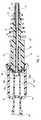
- FIGS. 1A-1Cprovide an example of the traditional method for forming a loop at the distal end of the tubing in order to prevent displacement of the tubing from a patient's body.
- a traditional drainage catheteris illustrated generally as catheter 1 , which includes hub 2 and tubing 3 .
- one end (not shown) of a cord, such as cord 4is affixed to the inside of hub 2 , while the opposing end of cord 4 extends through tubing 3 .
- Cord 4extends from hub 2 inside tubing 3 , then out of an exit opening at the distal end of the tubing such as opening 7 .
- Cord 4then extends back into a side entrance opening such as opening 6 , through tubing 3 and out of the proximal end of hub 2 , such that a free end of cord 4 is disposed outside hub 2 , as shown in FIG. 1 A.
- loop 9maintains catheter 1 within the selected portion of the body.
- the bodily fluiddrains into the catheter via entrance openings such as openings 5 illustrated in FIGS. 1A-1C. Once the bodily fluid drains into the entrance openings, the fluid flows down tubing 3 , and out of hub 2 .
- Cord 4must maintain its tension in order for loop 9 to remain in the tubing. Therefore, traditional methods have included securing the free end of cord 4 after it has been pulled tight. As such, cord 4 is able to maintain its tension during the period that bodily fluid is drained from the patient.
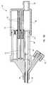
- One of the methods for securing cord 4 after it has been pulled tightincludes tying the free end of cord 4 to a fixed object, such as hub 2 of catheter 1 , as illustrated in FIG. 1B at knot 8 .
- tying the free end of cord 4 to a fixed objectmaintains the tension in cord 4 , problems arise with this traditional method.
- Another problem with the traditional methodincludes a risk that is presented after the practitioner secures the free end of the cord. Once the cord is secured, the excess is cut off with a sharp instrument.
- the risk presentedincludes that the sharp instrument used to cut off the excess cord can cause an accidental laceration to the practitioner.
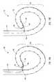
- a cordsuch as cord 4
- cord 4extends through the tubing, exits through opening 7 located at the distal end of the tubing, and re-enters a side opening of the tubing at opening 6 .
- opening 7located at the distal end of the tubing
- cord 4is exposed to bodily fluid, causing cord 4 to become encrusted.
- the encrustation of cord 4can prevent tubing 3 from straightening out, thereby restricting the catheter from being easily removed from the patient. Therefore, the encrusted cord causes increased difficulty when extracting the catheter from the patient's body.
- the present inventionis directed to drainage catheter systems, and to methods for coupling a drainage catheter system to a patient and decoupling the drainage catheter system from the patient.
- the inventionovercomes the above-mentioned difficulties by facilitating the process of securing a catheter to the patient's body, and by facilitating the removal of the catheter from the body.
- Embodiments according to the present inventiontake place in association with a catheter, such as a drainage catheter used for draining bodily fluid from a patient.
- a cathetersuch as a drainage catheter used for draining bodily fluid from a patient.
- Embodiments according to the present inventioninclude an elongate hollow cannula having a proximal end and a distal insertion end, a hub that can be placed in either an extended or contracted position, and a cord that extends from the hub and within at least a portion of the cannula.
- the cannulaincludes openings so that bodily fluid can enter. Once the bodily fluid enters the cannula, the fluid drains down the inside of the cannula and out of the hub.
- the cordhas first and second opposing ends and an intermediate portion therebetween.
- the cordextends within at least a portion of the cannula and can be attached to the distal insertion end of the cannula in a variety of manners.
- one end of the cordis attached to the hub with the intermediate portion of the cord extending through the cannula, exiting a side opening in the cannula, entering a first opening in the distal insertion end of the cannula, exiting a second opening in the distal insertion end of the cannula, and extending down through the cannula, with the second end of the cord attached to the hub.
- the cordcan resemble a lasso, having a loop on a first end that is fastened to the distal insertion end of the cannula. The cord then enters the cannula through a side opening and the second end is attached to the hub.
- a wireextends longitudinally through at least a portion of the cannula and can be used to secure the cord.
- a first end of the cordis attached to the hub and the intermediate portion of the cord extends down the cannula, out an opening at the distal end of the cannula, through a side opening in the cannula, loops around the wire, exits the cannula through the side opening, reenters the cannula through the opening at the distal end of the cannula, and extends along the length of the cannula to the hub, with the second end of the cord attached to the hub.
- the cordcan resemble a lasso, with a loop at a first end.
- a wireextends through the loop to secure the cord.
- the cordextends out of a side opening of the cannula, re-enters the cannula through a distal opening, and extends down the cannula, with the second end of the cord attached to the hub.
- the catheter cannulacan be inserted into a patient's body by way of a previously inserted guide wire, or by direct puncture, for example.
- the cathetercan be coupled to the body by pressing a proximal hub member towards a distal hub member to place the hub into a compressed position.
- one or more fingers within the proximal hub memberpushes the cord into channels within the distal hub member, causing the cord to create a force upon the distal insertion end of the cannula, in the direction of the hub.
- the forcecauses the distal insertion end of the cannula to form a loop that prevents the removal of the catheter from the patient's body.
- the proximal and distal hub memberscan be locked together in the contracted position for as long as the catheter is to be coupled to the body.
- the tensionis eliminated from the cord.
- the wireis moved in a proximal direction in the cannula, thereby releasing the cord from the wire, eliminating the tension in the cord, and enabling the removal of the catheter cannula from the body.
- a tear through materialis employed in the cannula.
- the cordcan be pulled to cause the cord to tear through the distal insertion end of the cannula, thereby eliminating the tension in the cord and enabling the removal of the cannula from the patient's body.
- the proximal and distal hub membersare unlocked and slid apart to eliminate the tension in the cord and to enable uncurling of the catheter distal insertion end and the removal of the cannula from the patient's body.
- FIG. 1Aillustrates an example of a traditional drainage catheter with a free end of a cord protruding out of the proximal end of the catheter hub;
- FIG. 1Billustrates an example of the traditional drainage catheter of FIG. 1A with the cord pulled tight and tied around the hub to create and maintain a loop at the end of the catheter tubing;
- FIG. 1Cillustrates a traditional method for threading a cord through the lumen of a catheter
- FIG. 2illustrates an exemplary embodiment of the present invention with the hub in an extended position
- FIG. 3illustrates the exemplary embodiment of FIG. 2 with the hub in a contracted position
- FIG. 4illustrates a cross-sectional view of the exemplary embodiment of FIG. 2 with the hub in an extended position without the cord in place;
- FIG. 5illustrates a cross-sectional view of the exemplary embodiment of FIG. 2 with the hub in an extended position, and with a cord threaded through the hub such that both ends of the cord are affixed to the distal hub member;
- FIG. 5Aillustrates an exemplary manner of affixing an end of a cord to a hub
- FIG. 6illustrates a cross-sectional view of the exemplary embodiment of FIG. 2 with the hub in a contracted position demonstrating how the finger of the proximal hub presses the cord into a channel of the distal hub member causing tension on the cord;
- FIG. 7illustrates another exemplary embodiment of the present invention and includes a hub in an extended position
- FIG. 8illustrates the exemplary embodiment of FIG. 7 with the hub in a contracted position
- FIG. 9illustrates an exploded view of the exemplary embodiment of FIG. 7;
- FIG. 9Aillustrates a rear end view of the distal hub member of FIG. 9
- FIG. 10illustrates a cross-sectional view of the exemplary embodiment of FIG. 7 with the hub in an extended position
- FIG. 11illustrates a cross-sectional view of the exemplary embodiment of FIG. 7 with the hub in a contracted position
- FIG. 12Aillustrates an exploded view of another exemplary embodiment of the present invention
- FIG. 12Billustrates the exemplary embodiment of FIG. 12A with the hub in an extended position
- FIG. 12Cillustrates the exemplary embodiment of FIG. 12A with the hub in a contracted position
- FIG. 13Aillustrates an exemplary method for threading a cord to form an anchoring configuration that secures the distal insertion end of the catheter to a patient as provided under an embodiment of the present invention
- FIG. 13Billustrates another exemplary method for threading a cord to form a configuration that secures the distal insertion end to a patient as provided under an embodiment of the present invention
- FIG. 13Cillustrates another exemplary configuration for securing the distal insertion end to a patient as provided under an embodiment of the present invention
- FIG. 14Aillustrates an exemplary method for threading a cord around a wire to form a configuration that secures the distal insertion end to a patient as provided under an embodiment of the present invention
- FIG. 14Billustrates another exemplary method for threading a cord around a wire to form a configuration that secures the distal insertion end to a patient as provided under an embodiment of the present invention.
- the present inventionrelates to catheter systems and more particularly to drainage catheter systems that are used for draining bodily fluids.
- the present inventionis also directed to methods for coupling a drainage catheter to a patient's body and decoupling the drainage catheter from the body, as will be further explained below.
- Those skilled in the artwill appreciate that the invention may be practiced in combination with a variety of differently sized catheters.
- a drainage catheter of the present inventionincludes a hub and a cannula that are in fluid communication with each other.
- FIGS. 2 and 3provide an exemplary embodiment of the present invention, illustrated generally as catheter 10 , which includes hub 12 and cannula 14 .
- hub 12is comprised of a proximal member, such as proximal hub member 16 , a distal member, such as distal hub member 18 , a fluid pathway extending therethrough, and a locking mechanism.
- Proximal hub member 16 and distal hub member 18are adjustably coupled together.
- proximal hub member 16can be pressed towards distal hub member 18 , thereby placing hub 12 into a contracted position, as illustrated in FIG. 3 .
- proximal hub member 16can be pulled away from distal hub member 18 , thereby placing hub 12 into an extended position, as illustrated in FIG. 2 .
- the illustrated embodimentfurther includes handle 20 for gripping onto distal hub member 18 to facilitate the process of placing hub 12 into a contracted or extended position.
- a locking mechanismis an example of a locking means for selectively locking hub 12 in the contracted position.
- the locking mechanismcan include a pin, a latch, a lever, or any other device or combination of devices that can hold proximal hub member 16 and distal hub member 18 in a specific position relative to each other.
- the locking mechanismcan include (i) a protrusion, such as pin 22 , in proximal hub member 16 ; and (ii) a mating channel, such as channel 24 in distal hub member 18 .
- a protrusionsuch as pin 22
- a mating channelsuch as channel 24 in distal hub member 18 .
- pin 22slides along channel 24 .
- proximal hub member 16can be rotated in such a way as to place pin 22 into locking portion 26 of channel 24 .
- hub 12can be maintained in the contracted position illustrated in FIG. 3 without further effort by a practitioner.
- Pin 22 and channel 24provide an example of a means for selectively locking hub 12 into a contracted position.
- a second locking portion of the channelcan maintain hub 12 in an extended position to facilitate the insertion of catheter 10 into a patient's body.
- catheter 10includes an elongate hollow cannula, such as cannula 14 .
- Cannula 14is a flexible, elongate tube having a proximal end in fluid communication with hub 12 , a distal insertion end for insertion into a cavity of the body and a plurality of openings.
- openings 15allow for bodily fluid to enter cannula 14 ;
- opening 13allows cord 17 , which is attached to hub 12 and extends within at least a portion of cannula 14 , to exit cannula 14 ; and openings 19 allow for the attachment of cord 17 to distal insertion end 21 of cannula 14 , as will be further explained below.
- the insertion of cannula 14 into a bodyis performed while hub 12 is in an extended position.
- cannula 14is manipulated to form an anchoring configuration, such as loop 32 , inside of the body to couple catheter 10 to the body and prevent cannula 14 from being inadvertently removed.
- an anchoring configurationsuch as loop 32
- the use of the cord in a variety of mannersallows for the formation of a number of different kinds of configurations that can be formed to couple the catheter to the patient's body.
- the anchoring configurationmay include a pigtail, a j-curve, a malecot having one or more wings, and so forth, as will be further explained below.
- Placing hub 12 into a contracted positioncauses an anchoring configuration to form, such as loop 32 , by placing tension on cord 17 and causing distal insertion end 21 of cannula 14 to approach opening 13 , as will be further explained below.
- Cannula 14remains in the patient's body as long as catheter 10 is used for draining bodily fluid. While cannula 14 is in the body, bodily fluid can enter catheter 10 through openings 15 , drain through cannula 14 , into hub 12 , and out of the end of hollow connector 30 of FIG. 3 .
- catheter 10is decoupled from the body.
- the decouplingtakes place by first twisting proximal hub member 16 to cause pin 22 to leave locking portion 26 of channel 24 .
- Proximal hub member 16can then be pulled away from distal hub member 18 to cause pin 22 to slide proximally along channel 24 , and place hub 12 back into an extended position.
- the anchoring configurationsuch as loop 32 , can be straightened to allow cannula 14 to be removed from the body.
- catheter 10is decoupled from the body by pulling on cord 17 , causing distal insertion end 21 of cannula 14 to tear and detach cord 17 from distal insertion end 21 .
- the proximal hub member 16is removed from the distal hub member 18 to allow access to cord 17 . Once cord 17 is accessible, cord 17 can be pulled to cause distal insertion end 21 of cannula 14 to tear and detach cord 17 from distal insertion end 21 .
- the attachment of cord 17 to hub 12further includes the attachment of cord 17 to proximal hub member 16 so that when the proximal hub member 16 is pulled away from the distal hub member 18 , cord 17 is also pulled to cause distal insertion end 21 of cannula 14 to tear and detach cord 17 from distal insertion end 21 .
- FIG. 4a cross-sectional diagram of hub 12 is provided to illustrate an embodiment of the present invention.
- a cordis not included.
- cannula 14is coupled to hub 12 by being inserted into a cavity of distal hub member 18 , such as cavity 40 , and abuts annular ridge 41 , thereby enabling hub 12 and cannula 14 to be in fluid communication with each other.
- Strain relief tube 45abuts annular ridge 43 and surrounds a portion 47 of cannula 14 to provide additional support.
- Hub 12 and cannula 14are hollow, thereby allowing bodily fluid to run from cannula 14 , through hub 12 via a fluid pathway extending therethrough, such as canal 42 , and out of proximal end 44 of catheter 10 .
- Two gaskets, such as rubber O-rings 48 and 50are positioned at an interface between proximal hub member 16 and distal hub member 18 to prevent the bodily fluid from flowing into undesirable locations.
- proximal hub member 16includes cylinder 52 and distal hub member 18 includes channel 54 , such that when proximal hub member 16 is selectively and removably pushed toward distal hub member 18 , cylinder 52 extends into channel 54 of distal hub member 18 .
- cylinder 52when a cord is attached to the hub, cylinder 52 functions as a finger that pushes the cord into channel 54 as proximal hub member 16 is pushed toward distal hub member 18 , thereby causing cannula 14 to form an anchoring configuration (i.e. a loop, j-curve, pigtail, malecot, etc.) when hub 12 is in a contracted position.
- one or more fingerscan be included that slide into one or more corresponding channels, thereby pushing a cord into the channels.
- a cross-sectional illustration of hub 12 in an extended positionis provided that includes a cord, illustrated as cord 60 .
- the cordcan be made from a variety of materials, such as, by way of example, silk, nylon, polyethylene, suture material, or a variety of other materials to allow cord 60 to be sufficiently flexible that it can be selectively pushed into or removed from one or more channels inside of the hub, yet is strong enough to handle the required tension.
- both of the opposing ends of cord 60are affixed to hub 12 . More specifically, both ends 62 a and 62 b of cord 60 are affixed to the proximal end of distal hub member 18 . (An exemplary manner of affixing ends 62 a and 62 b will be discussed below in association with FIG. 5A.)
- the intermediate portion of cord 60extends through canal 42 within cannula 14 . Therefore, in the embodiment illustrated in FIG. 5, when proximal hub member 16 is pushed toward distal hub member 18 , cylinder 52 forces cord 60 to enter into channel 54 , thereby increasing the amount of cord 60 within hub 12 and reducing the amount of cord 60 within cannula 14 .
- the reduction of the amount of cord 60 in cannula 14causes an anchoring configuration (i.e. a loop, j-curve, pigtail, malecot, etc.) to form at the distal insertion end of cannula 14 , as shown in FIG. 3 .
- an anchoring configurationi.e. a loop, j-curve, pigtail, malecot, etc.
- FIG. 5Aillustrates an exemplary manner of affixing the opposite ends of cord 60 to hub 12 .
- a first end of cord 60such as, by way of example, end 62 a
- pin 61 ais inserted (i.e., by being threaded or pushed) into aperture 63 a of, by way of example, the proximal end of distal hub member 18 .
- An adhesivecan be used to ensure that pin 61 a is maintained in aperture 63 a .
- Other manners of affixing the opposite ends of cord 60 to hub 12include the use of insert molding, an adhesive, a snap ring, a C-clamp, or the like, as will be further discussed below.
- FIG. 6illustrates hub 12 in a contracted position with cord 60 pressed into channel 54 .
- an anchoring configurationi.e. a loop, j-curve, pigtail, malecot, etc.
- loop 32 of FIG. 3is formed in distal insertion end of cannula 14 .
- hub 12can be maintained in a contracted position by employing a locking mechanism.
- pin 22has been placed in locking portion 26 of channel 24 of FIG. 2 to maintain hub 12 in the contracted position.
- hub 12includes O-rings 48 and 50 positioned at an interface between proximal hub member 16 and distal hub member 18 to prevent bodily fluid from flowing into undesirable locations.
- O-ring 48prevents bodily fluid from entering channel 54 when hub 12 is in a contracted position. As such, the bodily fluid that flows through canal 42 is directed out proximal end 44 .
- O-ring 50prevents any bodily fluid from escaping between proximal hub member 16 and distal hub member 18 . Therefore, when hub 12 is in an extended position as illustrated in FIG. 5, if any fluid happens to enter channel 54 , when proximal hub member 16 and distal hub member 18 are pushed together the fluid is forced into canal 42 and drains out proximal end 44 .
- the opposing ends of cord 60can be affixed to distal hub member 18 through a variety of different coupling means.
- the coupling meanscan include an insert molding, an adhesive, a pin (as illustrated in FIG. 5 A), a snap ring, a C-clamp, or the like.
- Connector 30may be coupled to a fluid collector, for example, which collects the bodily fluid that drains out of the catheter.
- catheter 70which includes hub 72 and cannula 74 .
- hub 72is comprised of a proximal member, such as proximal hub member 76 , a distal member, such as distal hub member 78 .
- a fluid pathwayextends through proximal and distal hub members 76 , 78 .
- Proximal hub member 76 and distal hub member 78are adjustably coupled together in such a way as to selectively allow proximal hub member 76 to approach distal hub member 78 , thereby placing hub 72 into a contracted position.
- the contracted position of hub 72is illustrated in FIG. 8 .
- a locking mechanismcan be used to selectively and removably lock hub 72 in the contracted position.
- proximal hub member 76can also be selectively allowed to retract from distal hub member 78 , thereby placing hub 72 into an extended position, as illustrated in FIG. 7 .
- the locking mechanismcan also be used to selectively and removably lock hub 72 in an extended position.
- the locking mechanismmay also allow for the complete decoupling of proximal hub member 76 from distal hub member 78 .
- the locking mechanismis an example of a locking means for selectively locking the proximal and distal hub members in the contracted position.
- catheter 70includes an elongate hollow cannula, such as cannula 74 , that is in fluid communication with hub 72 .
- Cannula 74is a flexible, elongate tube that can be inserted into a cavity of the body for drainage of bodily fluid, and includes a variety of fluid entrance openings 80 .
- a strain relief tube 73can surround a portion of cannula 74 to provide additional support.
- Cannula 74includes primary and secondary lumens, the primary lumen configured to receive fluid flowing therethrough and the secondary lumen configured to receive a wire therethrough, where the wire is any metallic or non-metallic elongate member, such as, by way of example, plastic, composite, etc., as will be further explained below.
- Cannula 74is an example of cannula means for defining a primary lumen and a secondary lumen.
- cannula 74into a body is performed while hub 72 is in an extended position. As illustrated in FIG. 8, once cannula 74 is inserted into the desired cavity of the body, hub 72 can be contracted such that cannula 74 forms an anchoring configuration inside the body, such as loop 82 , thereby coupling catheter 70 to the patient's body and preventing cannula 74 from being inadvertently removed from the body.
- Catheter 70includes a cord illustrated as cord 84 .
- a first end of cord 84is attached to hub 72 .
- Cord 84then extends down cannula 74 , exits distal insertion end 75 through opening 81 , reenters cannula 74 at opening 79 , wraps around a wire that extends longitudinally through at least a portion of cannula 74 , exits cannula 74 at opening 79 , enters distal insertion end 75 through opening 81 , and extends down cannula 74 , with the second end of cord 84 attached to hub 72 .
- catheter 70can be decoupled from the body.
- the decouplingtakes place by removing cap 85 , which has a wire attached that extends longitudinally through at least a portion of cannula 74 .
- the removal of cap 85 and the corresponding wireallows for a simple removal of cannula 74 from the body, as will be further explained below.
- hub 72includes proximal hub member 76 , distal hub member 78 , cap 85 , a flexible wire 92 , O-rings 86 and 88 , a coupling means, such as pin 111 , and a locking mechanism.
- Proximal hub member 76 and distal hub member 78can be selectively slid together to place hub 72 into a contracted position or can be selectively slid away from each other to place hub 72 into an extended position.
- the locking mechanismis an example of a locking means for selectively locking the proximal and distal hub members in the contracted position, employing, by way of example, a protrusion and a channel.
- FIG. 9Aprovides an end view of distal hub member 78 into which proximal hub member 76 slides.
- O-rings 86 and 88are positioned at an interface between proximal hub member 76 and distal hub member 78 to prevent bodily fluid from entering undesired locations, and a protrusion, such as hook 90 , in connection with either protrusion 110 or protrusion 112 maintains hub 72 in either an extended position or a contracted position, all of which will be further explained below.
- Distal hub member 78includes primary and secondary lumens therein.
- the primary lumenis configured to receive fluid flowing therethrough and the secondary lumen is configured to receive at least a portion of a flexible wire therethrough.
- Affixed to cap 85is wire 92 for assisting catheter 70 of FIG. 7 in being coupled to and decoupled from a patient's body.
- Cap 85can fit onto distal hub member 78 in a variety of manners, such as, by way of example, a snap fit or by screwing onto distal hub member 78 .
- a snap fitis illustrated that includes annular ridge 83 and mating annular groove 87 .
- annular ridge 83fits into annular groove 87 to hold cap 85 on distal hub member 78 .
- Cap 85can be selectively fit onto or removed from distal hub member 78 . Furthermore, since wire 92 is affixed to cap 85 , the fitting of cap 85 onto distal hub member 78 inserts wire 92 into the secondary lumen of the cannula. Likewise, the removal of cap 85 from distal hub member 78 retracts wire 92 from the secondary lumen of the cannula.
- FIGS. 10 and 11illustrate cross sectional diagrams of catheter 70 .
- catheter 70is illustrated with hub 72 in an extended position.
- catheter 70is illustrated with hub 72 in a contracted position.
- a locking mechanismcan be used to selectively and removably lock hub 72 in the contracted position.
- the locking mechanismis an example of a locking means for selectively locking the proximal and distal hub members in the contracted position.
- the locking meansutilizes, by way of example, a protrusion and a channel. Therefore, the locking mechanism illustrated in FIG. 11 includes, by way of example, hook 90 and protrusion 112 , which when in contact with each other can maintain hub 72 in the contracted position.
- the position of the proximal hub member 76 relative to the distal hub member 78affects the distal insertion end of cannula 74 .
- the distal insertion end of cannula 74can be extended so as to be in an extended position, as illustrated in FIG. 10 .
- an anchoring configurationi.e. a loop, j-curve, pigtail, malecot, etc. is formed at the distal insertion end of cannula 74 , as illustrated in FIG. 11 .
- a cordcan be used in a variety of manners to allow for the formation of a configuration to couple the catheter to the patient's body.
- a cordlabeled as cord 84
- the cordhas a first end attached to the hub and the cord extends down the primary lumen of the cannula, exits the distal insertion end, reenters the cannula at a side opening, wraps around a wire that extends longitudinally through the secondary lumen of the cannula, exits the cannula, reenters the cannula at the distal insertion end, and extends down the primary lumen with the second end being attached to the hub.
- FIGS. 10 and 11illustrate another manner of using a cord, opposed to the manner in which cord 84 of FIGS. 7 and 8 was used, to form a configuration such as a loop at the distal insertion end of the cannula.
- the cordlabeled as cord 100
- the second end of cord 100illustrated as end 101
- end 101is fastened to hub 72 .
- end 101is fastened to hub 72 by an insert molding, an adhesive, a pin (as illustrated in FIG. 5 A), a snap ring, a C-clamp, or the like.
- Cord 100extends down the length of the primary lumen of cannula 74 , exits an opening at the distal insertion end of cannula 74 , and the looped end of cord 100 enters the secondary lumen of cannula 74 through a side opening.
- Wire 92extends through the looped end of cord 100 , as will be further explained below.
- Tension on cord 100can cause cannula 74 to form an anchoring configuration at the distal insertion end of cannula 74 , such as loop 114 of FIG. 11 .
- the tensionis placed on cord 100 by pushing proximal hub member 76 toward distal hub member 78 , thereby causing fingers 102 a and 102 b to push cord 100 into respective channels 104 a and 104 b .
- the pushing of cord 100 into channels 104 a and 104 bcreates tension on cord 100 and results in the formation of loop 114 .
- catheter 70is inserted into a cavity of a patient's body while hub 72 is in an extended position. Once inside the body, catheter 70 is coupled to the body by pushing proximal hub member 76 toward distal hub member 78 , thereby causing loop 114 to form and preventing cannula 74 from accidentally escaping from the patient's body.
- Protrusion 112 and channel 108act as a locking mechanism that locks hub 72 in a contracted position.
- hook 90latches over protrusion 112 , thereby causing hub 72 to be maintained in the contracted position.
- Protrusion 112 and channel 108provide an example of a locking means for selectively locking the proximal and distal hub members in the contracted position.
- Cannula 74includes openings 116 whereby bodily fluid can enter. Once in the cannula, the bodily fluid flows down cannula 74 , through channel 118 , and out end 120 .
- O-rings 115 and 116are positioned at an interface between proximal hub member 76 and distal hub member 78 to prevent bodily fluid from entering into undesired locations.
- O-ring 115prevents the bodily fluid from entering channels 104 a and 104 b when hub 72 is in the contracted position.
- O-ring 116forces any bodily fluid out proximal end 120 that may have entered channels 104 a and 104 b while hub 72 was in an extended position. Therefore, O-rings 115 and 116 prevent bodily fluid from escaping from a portion of hub 72 other than proximal end 120 .
- cap 85can be fastened onto distal hub portion 78 .
- Affixed to cap 85is a flexible wire, such as wire 92 .
- the flexible wireis any metallic or non-metallic elongate member, such as, by way of example, plastic, composite, etc.
- wire 92is made of nitinol. Wire 92 extends into hub 72 through lumen 106 of FIG. 10, down the secondary lumen of cannula 74 , and is used for securing cord 100 to cannula 74 to enable the formation of an anchoring configuration in the distal insertion end of cannula 74 such as loop 114 .
- the use of the flexible wireimproves the structural integrity of cannula 74 by preventing kinking and allows for an easier insertion of cannula 74 into the patient's body by creating an amount of stiffness and strength to the catheter. Moreover, the stiffness and strength provided by the flexible wire allows for thinner walls of cannula 74 and a larger lumen size of the primary lumen of cannula 74 for a greater flow of bodily fluid.
- the looped end of cord 100is released from wire 92 .
- the releasing of the looped end of cord 100 from wire 92releases the tension in cord 100 , thereby allowing catheter 70 to be decoupled from the patient's body by removing cannula 74 from the body, as will be further explained below.
- FIG. 12Aprovides an exploded, cross-sectional diagram of hub 122 .
- hub 122includes proximal hub member 128 , and a two-part distal hub member 127 .
- the two-part distal hub membercomprises a first hub member 126 and a second hub member 124 .
- First and second hub memberscan be combined to form distal hub member 127 .
- hub member 127is initially formed in two parts which are conveniently combined in the molding and assembly process.
- Hub 122further includes support 123 , cap 125 , a coupling means, such as pin 133 , and a locking mechanism, such as the combination of protrusion 129 and channel 138 which provide another example of a locking means for selectively locking the proximal and distal hub members in the contracted position.
- Proximal hub member 128 and distal hub member 127can be selectively slid together to place hub 122 into a contracted position or can be selectively slid away from each other to place hub 122 into an extended position.
- Channel 137provides a location for housing an 0 -ring.
- an elongate cannula 135(FIG. 12B) to form a drainage catheter.
- Hub 122includes primary and secondary lumens therein.
- the primary lumenis configured to receive fluid flowing therethrough and the secondary lumen is configured to receive at least a portion of a flexible wire therethrough.
- Affixed to cap 125is the flexible wire (not shown) for assisting the drainage catheter in being coupled to and decoupled from a patient's body.
- one embodimentincludes the proximal end of the flexible wire being bent in a U-shape so as to fit snugly within cap 125 .
- the U-shaped endcan be bonded to the cap 125 through the use of an adhesive.
- Cap 125fits onto distal hub member 127 in a variety of manners, such as, by way of example, a snap fit or by threading onto distal hub member 127 .
- Cap 125can be selectively fit onto or removed from distal hub member 127 . Furthermore, since the flexible wire is affixed to cap 125 , the fitting of cap 125 onto distal hub member 127 inserts the flexible wire (not shown) into the secondary lumen of the cannula (not shown). Likewise, the removal of cap 125 from distal hub member 127 retracts the flexible wire from the secondary lumen of the cannula.
- FIGS. 12B and 12Cillustrate cross sectional diagrams of hub 122 .
- FIG. 12Billustrates hub 122 in an extended position
- FIG. 12Cillustrates hub 122 in a contracted position.
- an anchoring configurationi.e. a loop, j-curve, pigtail, malecot, etc.
- a cordcan be used in a variety of manners to allow for the formation of an anchoring configuration to couple the catheter to the patient's body.
- the cordlabeled as cord 131
- the cordresembles a lasso, having a loop on a first end.
- the second end of cord 131is fastened to hub 122 by use of a coupling means, such as pin 133 , as described above in relation to FIG. 5 A.
- a coupling meansinclude an insert molding, an adhesive, a snap ring, a C-clamp, or the like.
- Tension on cord 131can cause the cannula (not shown) to form an anchoring configuration at the distal insertion end of the cannula.
- the tensionis placed on cord 131 by forcing cord 131 into channels 134 , and is accomplished by pushing proximal hub member 128 toward distal hub member 127 , thereby causing fingers 132 to push cord 131 into respective channels 134 (as illustrated in FIG. 12 C).
- Wire 135extends into hub 122 , down the secondary lumen of the cannula, and is used for securing cord 131 to the cannula to enable the formation of an anchoring configuration in the distal insertion end of the cannula.
- the looped end of cord 131is released from wire 135 .
- the releasing of the looped end of cord 131releases the tension in cord 131 , thereby allowing the drainage catheter to be decoupled from the patient's body by removing cannula 74 from the body, as will be further explained below.
- Hubs 12 , 72 and 122 disclosed aboveare each examples of a hub means coupled to the proximal end of a cannula for receiving fluid entering the distal insertion end of the cannula and for selectively tightening a cord upon movement of the hub means.
- FIGS. 13A-14Billustrate exemplary embodiments under the present invention for threading a cord to facilitate the decoupling of the cannula from the patient's body.
- FIG. 13Aan exemplary embodiment for threading the cord is illustrated, which can be used in connection with a variety of hub designs, such as those disclosed herein.
- the distal insertion end of a catheter cannulais illustrated generally as cannula 150 and includes a plurality of fluid entrance openings, such as opening 156 , to allow bodily fluid to enter cannula 150 .
- one end of cord 154is affixed to the catheter hub and the other end extends along the hollow interior of the cannula, out a side opening such as opening 160 , into the distal insertion end of cannula 150 through an opening such as opening 162 , out of the distal insertion end of cannula 150 through an opening such as opening 164 , back through a side opening such as opening 160 and is affixed to the catheter hub as explained in relation to FIG. 5 above.
- openings 162 and 164are spaced closely together.
- a loopis formed in cannula 150 when the catheter hub is placed in a contracted position.
- placing the hub in a contracted positioncauses cord 154 to be inserted into one or more channels, thereby shortening the amount of cord 154 in cannula 150 and causing an anchoring configuration, such as loop 152 to form.
- the hubmay be locked into the contracted position while drainage takes place.
- the bodily fluidenters the drainage openings, such as opening 156 , flows down cannula 150 , through the catheter hub and out of the end of the hub or into a connector coupled thereto.
- cannula 150is decoupled from the patient's body.
- the process of decouplingcomprises relaxing cord 154 such that cannula 150 can be straightened and thus removed from the body. This may be accomplished, by way of example, by extending hub 12 into an extended position as illustrated in FIG. 2 .
- the process of decoupling according to an embodiment of the present inventionincludes pulling cord 154 of FIG. 13 A. The pulling causes the portion of the cannula between openings 162 and 164 , illustrated as cannula portion 166 , to tear away. With cannula portion 166 torn way, cord 154 is released from the distal insertion end of cannula 150 . Therefore, upon pulling on the catheter, cannula 150 can be slid out of the body to decouple the catheter from the patient's body. Alternatively, cord 154 could be cut to allow for the removal of the catheter from the body.
- catheter cannulaillustrated generally as cannula 170
- cannula 170includes a plurality of fluid entrance openings, such as opening 176 , to allow bodily fluid to enter cannula 170 .
- Cord 174resembles a lasso having a loop at one end.
- the non-looped end of cord 174is affixed to the catheter hub and the looped end extends through the cannula, out a side opening such as opening 178 , and is attached to the distal insertion end of cannula 170 by entering openings 180 and 182 , thereby surrounding distal cannula portion 184 .
- openings 180 and 182are spaced closely together.
- a loopis formed in cannula 170 under embodiments of the present invention when the catheter hub is placed in a contracted position.
- placing the hub in a contracted positioncauses cord 174 to be inserted into one or more channels, thereby shortening the amount of the cord in cannula 170 and causing an anchoring configuration, such as loop 172 to form.
- the hubcan be locked into the contracted position while drainage takes place.
- the bodily fluidenters the fluid entrance openings, such as opening 176 , runs down cannula 170 , through the catheter hub and out the proximal end of the catheter.
- cannula 170is decoupled from the patient's body.
- the process of decouplingcan include pulling cord 174 .
- the pullingcauses distal cannula portion 184 to tear away, thereby releasing cord 174 from the distal insertion end of cannula 170 .
- cord 174no longer attached to the distal insertion end of cannula 170 , the catheter can be decoupled from the patient's body.
- cannula 170can be slid out of the body, thereby decoupling the catheter from the patient's body.
- cord 174could be cut to allow for the removal of the catheter from the body.
- FIG. 13Cillustrates the formation of a malecot configuration, referred to generally as malecot 186 .
- a first end of cord 188is affixed to the hub and a second end of cord 188 is affixed to distal cannula tip 187 .
- the configurationis formed when the hub is placed into a contracted position that creates tension in cord 188 and pulls distal cannula tip 187 toward the hub.
- the movement of the distal cannula tip toward the hubcauses one or more wings to be formed, such as wing 189 .
- the one or more wingsprevent the cannula from being removed from the patient's body, thereby coupling the catheter to the body.
- the hubis placed back into an extended position to eliminate the tension in cord 188 and to allow the cannula to straighten so that it can be removed from the patient's body.
- FIG. 14Aan exemplary embodiment is illustrated for threading a cord that can be used in connection with any of the hub designs disclosed herein that employ a flexible wire.
- the distal portion of a catheter cannulais illustrated generally as cannula 190 and includes primary and secondary lumens, the primary lumen configured to receive fluid flowing therethrough and the secondary lumen configured to receive a flexible wire there through.
- Cannula 190also includes a plurality of fluid entrance openings, such as opening 196 , to allow bodily fluid to enter cannula 190 .
- a first end of cord 194is affixed to the catheter hub and the other end extends down primary lumen 198 of cannula 190 , exists cannula 190 through an opening, such as opening 204 , enters the secondary lumen 200 through opening 208 , wraps around the flexible wire, such as wire 202 , exits secondary lumen 200 through opening 208 , re-enters primary lumen 198 through opening 204 , extends down primary lumen 198 of cannula 190 and is affixed to the hub.
- the wire and the cordextend down the same lumen.
- secondary lumen 200extends down to or near distal tip portion 211 of cannula 190 .
- a first end of the cordis affixed to the catheter hub and the other end extends down secondary lumen 200 , exits cannula 190 through an opening at or near distal tip portion 211 , re-enters secondary lumen 200 through an opening such as opening 208 , wraps around wire 202 , exits secondary lumen 200 through opening 208 , re-enters secondary lumen 200 through an opening at or near distal tip portion 211 , extends down secondary lumen 200 of cannula 190 and is affixed to the catheter hub.
- wire 202is used to secure cord 194 and can be made of a variety of materials, such as nitinol, stainless steel, plastic, or another material or combination of materials to allow wire 202 to have the strength necessary to secure cord 194 and the flexibility necessary to allow the catheter to bend.
- Cannula 190is an example of cannula means for defining a primary lumen and a secondary lumen. In yet another embodiment, however, the cannula includes only one lumen and the flexible wire extends down the lumen. Nevertheless, in accordance with the preferred embodiment, the cannula includes a plurality of lumens, such as, by way of example, a primary lumen and a secondary lumen, with the flexible wire extending down the secondary lumen.
- the cannulaincludes a primary lumen and a secondary lumen and the primary lumen is configured to receive fluid flowing therethrough and the secondary lumen is configured to receive a flexible wire therethrough
- the diameter of the primary lumencan be large to allow for greater flow of the bodily liquid while the diameter of the secondary lumen can be smaller to accommodate the flexible wire.
- two cannulasare affixed in a parallel fashion with each other, one cannula configured to receive flowing liquid, the other configured to received the wire.
- This embodimentis another example of cannula means for defining a primary lumen and a secondary lumen.
- the use of one cannula having a plurality of lumensis preferred, as it facilitates the insertion of the catheter into the patient's body.
- the embodiment illustrated in FIG. 14Aincludes primary lumen 198 , secondary lumen 200 , and wire 202 , made, by way of example, of nitinol, which extends down secondary lumen 200 .
- An anchoring configurationis formed in cannula 190 under the present invention when the hub is placed in a contracted position.
- placing the hub into a contracted positioncauses cord 194 to be inserted into one or more channels within the hub, thereby shortening the amount of cord in cannula 190 and causing loop 192 to form.
- the hubcan be locked in the contracted position while drainage takes place.
- the bodily fluidenters the fluid entrance openings, such as opening 196 , drains down the cannula, through the catheter hub and out the proximal end of the catheter.
- the process of decoupling the catheter from the patient's bodyincludes removing or displacing wire 202 so that cord 194 is no longer wrapped around wire 202 .
- the removal of wire 202takes place, by way of example, upon removing cap 85 of FIG. 8, to which wire 202 can be attached, and pulling wire 202 out of secondary lumen 200 .
- the displacement of wire 202includes removing the cap and then retracting wire 202 from cord 194 .
- the removal or displacement of wire 202releases cord 194 and allows cannula 190 to slide out of the patient's body upon pulling on the catheter.
- cord 194can be cut to release cord 194 from wire 202 to allow for the removal of cannula 190 .
- Releasing cord 194eliminates the tension in cord 194 and thereby eliminates the possibility of cord 194 being tight and slicing through the patient's bodily tissue.
- the removal of cannula 190decouples the catheter from the patient's body.
- cannula 210includes primary and secondary lumens.
- Cannula 210is another example of cannula means for defining a primary lumen and a secondary lumen.
- the primary lumenis configured to receive fluid flowing therethrough and the secondary lumen is configured to receive a wire therethrough.
- Cannula 210further includes a plurality of fluid entrance openings, such as opening 216 , to allow bodily fluid to enter the cannula.
- the illustrated embodimentincludes a cord that has a loop, illustrated as loop 225 , at one end.
- the non-looped end of cord 214is affixed to the catheter hub and the looped end extends down primary lumen 218 , out opening 224 , and into secondary lumen 200 .
- a flexible wire, such as wire 220extends through the loop in cord 214 , thereby securing the cord.
- the wire and cordextend down the same lumen.
- the secondary lumen 200extends down to or near distal tip portion 211 of cannula 210 .
- a non-looped end of the cordis affixed to the catheter hub and the looped end extends down secondary lumen 200 , exits secondary lumen 200 through an opening at or near distal tip portion 211 , and re-enters secondary lumen 200 through opening 208 .
- a flexible wireextends through the loop to secure the cord.
- Wire 220is used to secure cord 214 and can be made of a variety of materials, such as nitinol, stainless steel, plastic, or another material or combination of materials to allow wire 220 to have the strength necessary to secure cord 214 and the flexibility necessary to allow the catheter to bend.
- An anchoring configurationsuch as loop 212
- cannula 210under the present invention when the catheter hub is placed in a contracted position.
- placing the hub in a contracted positioncauses cord 214 to be inserted into one or more channels within the hub, thereby shortening the amount of cord in cannula 210 and causing the formation of an anchoring configuration, such as loop 212 .
- the hubis locked into the contracted position while drainage takes place.
- the bodily fluidenters fluid entrance openings, such as opening 216 , flows down cannula 210 , through the catheter hub and out the proximal end of the catheter.
- cannula 150is decoupled from the patient's body.
- the process of decoupling according to the embodiment illustrated in FIG. 14Bincludes removing wire 220 from lumen 200 or displacing it longitudinally away from cord 214 .
- cord 214can be cut to release cord 214 from wire 220 to allow for the removal of cannula 190 .
- the removal of wire 220releases cord 214 and allows for cannula 210 to be slid out of the body upon pulling on the catheter.
- Releasing cord 214eliminates the tension in cord 214 and thereby eliminates the possibility of cord 214 being tight and slicing through the patient's bodily tissue.
- the removal of cannula 201decouples the catheter from the patient's body.
- the lumensare separate and distinct, rather than having an opening which connects the lumens in fluid communication.
- primary lumen 198is separate and distinct from secondary lumen 200 , for example. Consequently, fluid flowing through primary lumen 198 does not flow into secondary lumen 200 .
- secondary lumen 200does not become filled with fluid flowing from primary lumen 198 . This prevents fluid from primary lumen 198 from encrusting secondary lumen 200 , which could clog secondary lumen 200 and prevent a wire 202 from being removed therefrom.
- the secondary lumene.g., secondary lumen 200
- the corde.g., cord 194 (FIG. 14A) extends along the distal insertion end of the cannula and extends out of a distal tip portion, e.g., distal tip portion 211 (FIG. 14 A), of the distal insertion end of the cannula.
- cord 194extends along the anchoring configuration (e.g., loop 192 ) when the cord is tightened. Since cord 194 extends along the anchoring configuration, wire 202 can be straight within the distal portion of the secondary lumen, rather than being required to curve through the anchoring configuration. This can make tightening more convenient because the practitioner is not required to bend the wire.
- the amount of cord 194 extending out of the distal insertion endis minimal, reducing potential encrustation and possible injury to the patient.
- the cordextends from another portion other than the distal tip portion, e.g., from a portion of the cannula preceding the anchoring configuration.
- the wirecan be configured to curve through the anchoring configuration.
- cannula means for defining a primary lumen and a secondary lumenare available for use in the present invention, such as those disclosed herein or any other structure having a first lumen and a second lumen.
- the processes of coupling a catheter to a patient's body and decoupling the catheter from the bodyare facilitated, by way of example, according to the description of the embodiments provided above.
- the present inventionmay also be embodied in other specific forms without departing from its spirit or essential characteristics.
- the described embodimentsare to be considered in all respects only as illustrative and not restrictive.
- the scope of the inventionis, therefore, indicated by the appended claims rather than by the foregoing description. All changes that come within the meaning and range of equivalency of the claims are to be embraced within their scope.
Landscapes
- Health & Medical Sciences (AREA)
- Life Sciences & Earth Sciences (AREA)
- Engineering & Computer Science (AREA)
- Anesthesiology (AREA)
- Biophysics (AREA)
- Pulmonology (AREA)
- Biomedical Technology (AREA)
- Heart & Thoracic Surgery (AREA)
- Hematology (AREA)
- Animal Behavior & Ethology (AREA)
- General Health & Medical Sciences (AREA)
- Public Health (AREA)
- Veterinary Medicine (AREA)
- Mechanical Engineering (AREA)
- Media Introduction/Drainage Providing Device (AREA)
Abstract
Description
1. The Field of the Invention
The present invention relates to catheter systems and more particularly to drainage catheter systems that are used for draining bodily fluids from a patient. The present invention is also directed to methods for coupling a drainage catheter system to a patient's body and decoupling the drainage catheter from the body.
2. The Prior State of the Art
One of the traditional methods for draining bodily fluids includes inserting a catheter into a cavity of a patient's body. The catheter is typically introduced either over a previously inserted guide wire or by direct puncture. Catheters are used in procedures for draining bodily fluids from, by way of example, the kidneys, the liver, and from other organs. Catheters are also used to drain bodily fluid from the chest, abdominal cavities, and from abscesses located in various areas of the body. One of the challenges of using a catheter for draining bodily fluid is its propensity to be accidentally removed from a patient's body. Catheters have traditionally included straight tubing that, upon movement of the patient or accidental collision, can escape the patient's body. In order to prevent displacement of the tubing from the patient's body, various catheters have been developed that are configured to be anchored inside the patient's body.
FIGS. 1A-1C provide an example of the traditional method for forming a loop at the distal end of the tubing in order to prevent displacement of the tubing from a patient's body. In FIG. 1A, a traditional drainage catheter is illustrated generally ascatheter 1, which includeshub 2 andtubing 3. As illustrated, one end (not shown) of a cord, such ascord 4, is affixed to the inside ofhub 2, while the opposing end ofcord 4 extends throughtubing 3. Cord4 extends fromhub 2 insidetubing 3, then out of an exit opening at the distal end of the tubing such as opening7.Cord 4 then extends back into a side entrance opening such as opening6, throughtubing 3 and out of the proximal end ofhub 2, such that a free end ofcord 4 is disposed outsidehub 2, as shown in FIG.1A.
Upon insertingcatheter 1 into the patient's body, the free end ofcord 4 that protrudes out ofhub 2 can be pulled tight, causing a loop to be formed intubing 3, as illustrated in FIG. 1B asloop 9.Loop 9 maintainscatheter 1 within the selected portion of the body. The bodily fluid drains into the catheter via entrance openings such asopenings 5 illustrated in FIGS. 1A-1C. Once the bodily fluid drains into the entrance openings, the fluid flows downtubing 3, and out ofhub 2.
One problem experienced by practitioners using this traditional method is that the process of tying the free end ofcord 4 can become cumbersome. At times the challenge of securingcord 4 is so great that the free end cannot be tied. Moreover, whencord 4 is tied and secured, the knot can have tendencies to slip, thereby causing the tension in the cord to decrease. The decrease in cord tension causes the loop to relax.
Another problem with the traditional method includes a risk that is presented after the practitioner secures the free end of the cord. Once the cord is secured, the excess is cut off with a sharp instrument. The risk presented includes that the sharp instrument used to cut off the excess cord can cause an accidental laceration to the practitioner.
Another problem with the traditional method occurs during the extraction of the catheter from the patient's body. Under a traditional drainage catheter design, and as further illustrated in FIG. 1C, a cord, such ascord 4, extends through the tubing, exits through opening7 located at the distal end of the tubing, and re-enters a side opening of the tubing at opening6. Throughout the period of drainage into entrance openings, such as opening5,cord 4 is exposed to bodily fluid, causingcord 4 to become encrusted. At the time when the tubing is to be removed from the patient's body, the encrustation ofcord 4 can preventtubing 3 from straightening out, thereby restricting the catheter from being easily removed from the patient. Therefore, the encrusted cord causes increased difficulty when extracting the catheter from the patient's body.
Another problem with the traditional method is presented when the catheter needs to be relocated, replaced, or removed. Oncecord 4 is secured, it can be difficult to untie knot8 of FIG.1B. Therefore, the practitioner's ability to relocate, replace, or remove the catheter is restricted because of the difficulty to untie knot8. Moreover, if the excess ofcord 4 has been cut off, the cord may no longer be long enough to allow the catheter to be relocated.
It would, therefore, be an advancement in the art to be able to secure the catheter without having to tie the free end of a cord. It would also be desirable if the process of securing the catheter were simplified. Furthermore, it would be desirable if the process of securing the catheter could be performed by one hand. It would be an advancement in the art if the method of affixing the cord prevented any slippage that would cause the tension in the cord to relax. It would also be desirable if once secured, the excess cord did not have to be trimmed. Moreover, it would be an advancement in the art if the removal of the catheter from the patient's body was not affected by the encrustation of the cord.
The present invention is directed to drainage catheter systems, and to methods for coupling a drainage catheter system to a patient and decoupling the drainage catheter system from the patient. The invention overcomes the above-mentioned difficulties by facilitating the process of securing a catheter to the patient's body, and by facilitating the removal of the catheter from the body.
Implementation of the present invention takes place in association with a catheter, such as a drainage catheter used for draining bodily fluid from a patient. Embodiments according to the present invention include an elongate hollow cannula having a proximal end and a distal insertion end, a hub that can be placed in either an extended or contracted position, and a cord that extends from the hub and within at least a portion of the cannula. The cannula includes openings so that bodily fluid can enter. Once the bodily fluid enters the cannula, the fluid drains down the inside of the cannula and out of the hub.
The cord has first and second opposing ends and an intermediate portion therebetween. The cord extends within at least a portion of the cannula and can be attached to the distal insertion end of the cannula in a variety of manners. In one embodiment, one end of the cord is attached to the hub with the intermediate portion of the cord extending through the cannula, exiting a side opening in the cannula, entering a first opening in the distal insertion end of the cannula, exiting a second opening in the distal insertion end of the cannula, and extending down through the cannula, with the second end of the cord attached to the hub. Optionally, the cord can resemble a lasso, having a loop on a first end that is fastened to the distal insertion end of the cannula. The cord then enters the cannula through a side opening and the second end is attached to the hub.
In another embodiment, a wire extends longitudinally through at least a portion of the cannula and can be used to secure the cord. In this embodiment, a first end of the cord is attached to the hub and the intermediate portion of the cord extends down the cannula, out an opening at the distal end of the cannula, through a side opening in the cannula, loops around the wire, exits the cannula through the side opening, reenters the cannula through the opening at the distal end of the cannula, and extends along the length of the cannula to the hub, with the second end of the cord attached to the hub. Similarly, the cord can resemble a lasso, with a loop at a first end. A wire extends through the loop to secure the cord. The cord extends out of a side opening of the cannula, re-enters the cannula through a distal opening, and extends down the cannula, with the second end of the cord attached to the hub.
The catheter cannula can be inserted into a patient's body by way of a previously inserted guide wire, or by direct puncture, for example. Once inside of the patient's body, the catheter can be coupled to the body by pressing a proximal hub member towards a distal hub member to place the hub into a compressed position. In one embodiment, by pressing the proximal hub member towards the distal hub member, one or more fingers within the proximal hub member pushes the cord into channels within the distal hub member, causing the cord to create a force upon the distal insertion end of the cannula, in the direction of the hub. The force causes the distal insertion end of the cannula to form a loop that prevents the removal of the catheter from the patient's body. In one embodiment, the proximal and distal hub members can be locked together in the contracted position for as long as the catheter is to be coupled to the body.
To permit extraction of the catheter, the tension is eliminated from the cord. In the embodiments employing a wire, the wire is moved in a proximal direction in the cannula, thereby releasing the cord from the wire, eliminating the tension in the cord, and enabling the removal of the catheter cannula from the body. In another embodiment, a tear through material is employed in the cannula. In this embodiment, the cord can be pulled to cause the cord to tear through the distal insertion end of the cannula, thereby eliminating the tension in the cord and enabling the removal of the cannula from the patient's body. In yet another embodiment, the proximal and distal hub members are unlocked and slid apart to eliminate the tension in the cord and to enable uncurling of the catheter distal insertion end and the removal of the cannula from the patient's body.
Additional features and advantages of the present invention will be set forth in the description that follows, and in part will be obvious from the description, or may be learned by the practice of the invention. The features and advantages of the invention may be realized and obtained by means of the instruments and combinations particularly pointed out in the appended claims. These and other features of the present invention will become more fully apparent from the following description and appended claims, or may be learned by the practice of the invention as set forth hereinafter.
In order that the manner in which the above recited and other advantages and features of the invention are obtained, a more particular description of the present invention briefly described above will be rendered by reference to specific embodiments thereof that are illustrated in the appended drawings. Understanding that the drawings depict only typical embodiments of the invention and are not therefore to be considered to be limiting of its scope, the invention will be described and explained with additional specificity and detail through the use of the accompanying drawings in which:
FIG. 1A illustrates an example of a traditional drainage catheter with a free end of a cord protruding out of the proximal end of the catheter hub;
FIG. 1B illustrates an example of the traditional drainage catheter of FIG. 1A with the cord pulled tight and tied around the hub to create and maintain a loop at the end of the catheter tubing;
FIG. 1C illustrates a traditional method for threading a cord through the lumen of a catheter;
FIG. 2 illustrates an exemplary embodiment of the present invention with the hub in an extended position;
FIG. 3 illustrates the exemplary embodiment of FIG. 2 with the hub in a contracted position;
FIG. 4 illustrates a cross-sectional view of the exemplary embodiment of FIG. 2 with the hub in an extended position without the cord in place;
FIG. 5 illustrates a cross-sectional view of the exemplary embodiment of FIG. 2 with the hub in an extended position, and with a cord threaded through the hub such that both ends of the cord are affixed to the distal hub member;
FIG. 5A illustrates an exemplary manner of affixing an end of a cord to a hub;
FIG. 6 illustrates a cross-sectional view of the exemplary embodiment of FIG. 2 with the hub in a contracted position demonstrating how the finger of the proximal hub presses the cord into a channel of the distal hub member causing tension on the cord;
FIG. 7 illustrates another exemplary embodiment of the present invention and includes a hub in an extended position;
FIG. 8 illustrates the exemplary embodiment of FIG. 7 with the hub in a contracted position;
FIG. 9 illustrates an exploded view of the exemplary embodiment of FIG. 7;
FIG. 9A illustrates a rear end view of the distal hub member of FIG. 9;
FIG. 10 illustrates a cross-sectional view of the exemplary embodiment of FIG. 7 with the hub in an extended position;
FIG. 11 illustrates a cross-sectional view of the exemplary embodiment of FIG. 7 with the hub in a contracted position;
FIG. 12A illustrates an exploded view of another exemplary embodiment of the present invention;
FIG. 12B illustrates the exemplary embodiment of FIG. 12A with the hub in an extended position;
FIG. 12C illustrates the exemplary embodiment of FIG. 12A with the hub in a contracted position;
FIG. 13A illustrates an exemplary method for threading a cord to form an anchoring configuration that secures the distal insertion end of the catheter to a patient as provided under an embodiment of the present invention;
FIG. 13B illustrates another exemplary method for threading a cord to form a configuration that secures the distal insertion end to a patient as provided under an embodiment of the present invention;
FIG. 13C illustrates another exemplary configuration for securing the distal insertion end to a patient as provided under an embodiment of the present invention;
FIG. 14A illustrates an exemplary method for threading a cord around a wire to form a configuration that secures the distal insertion end to a patient as provided under an embodiment of the present invention; and
FIG. 14B illustrates another exemplary method for threading a cord around a wire to form a configuration that secures the distal insertion end to a patient as provided under an embodiment of the present invention.
The description of the present invention utilizes diagrams that illustrate either the structure or processing of embodiments for implementing the systems and methods of the present invention. Using the diagrams in this manner to present the invention should not be construed as limiting its scope. Furthermore, the headings and subheadings employed in this description are for convenience of the reader only and are not to be construed as limiting in any sense.
The present invention relates to catheter systems and more particularly to drainage catheter systems that are used for draining bodily fluids. The present invention is also directed to methods for coupling a drainage catheter to a patient's body and decoupling the drainage catheter from the body, as will be further explained below. Those skilled in the art will appreciate that the invention may be practiced in combination with a variety of differently sized catheters.
The Hub and its Relationship to the Distal Insertion End of the Cannula
One manner in which the present invention facilitates the coupling of a catheter to a patient's body and eases the decoupling of the catheter from the body regards the design and workings of the hub, and its relationship to the distal insertion end of the cannula. A drainage catheter of the present invention includes a hub and a cannula that are in fluid communication with each other. FIGS. 2 and 3 provide an exemplary embodiment of the present invention, illustrated generally ascatheter 10, which includeshub 12 andcannula 14.
Referring first to FIG. 2,hub 12 is comprised of a proximal member, such asproximal hub member 16, a distal member, such asdistal hub member 18, a fluid pathway extending therethrough, and a locking mechanism.Proximal hub member 16 anddistal hub member 18 are adjustably coupled together. By way of example, in one embodiment of the present invention,proximal hub member 16 can be pressed towardsdistal hub member 18, thereby placinghub 12 into a contracted position, as illustrated in FIG.3. Similarly,proximal hub member 16 can be pulled away fromdistal hub member 18, thereby placinghub 12 into an extended position, as illustrated in FIG.2. The illustrated embodiment further includes handle20 for gripping ontodistal hub member 18 to facilitate the process of placinghub 12 into a contracted or extended position.
A locking mechanism is an example of a locking means for selectively lockinghub 12 in the contracted position. The locking mechanism can include a pin, a latch, a lever, or any other device or combination of devices that can holdproximal hub member 16 anddistal hub member 18 in a specific position relative to each other.
By way of example, in the embodiment shown, the locking mechanism can include (i) a protrusion, such aspin 22, inproximal hub member 16; and (ii) a mating channel, such aschannel 24 indistal hub member 18. Whenproximal hub member 16 is pushed towarddistal hub member 18,pin 22 slides alongchannel 24. When in the fully contracted position,proximal hub member 16 can be rotated in such a way as to placepin 22 into lockingportion 26 ofchannel 24. As such,hub 12 can be maintained in the contracted position illustrated in FIG. 3 without further effort by a practitioner.Pin 22 andchannel 24 provide an example of a means for selectively lockinghub 12 into a contracted position. In another embodiment, a second locking portion of the channel can maintainhub 12 in an extended position to facilitate the insertion ofcatheter 10 into a patient's body.
Referring back to FIG. 2,catheter 10 includes an elongate hollow cannula, such ascannula 14.Cannula 14 is a flexible, elongate tube having a proximal end in fluid communication withhub 12, a distal insertion end for insertion into a cavity of the body and a plurality of openings. By way of example,openings 15 allow for bodily fluid to entercannula 14; opening13 allowscord 17, which is attached tohub 12 and extends within at least a portion ofcannula 14, to exitcannula 14; andopenings 19 allow for the attachment ofcord 17 todistal insertion end 21 ofcannula 14, as will be further explained below. The insertion ofcannula 14 into a body is performed whilehub 12 is in an extended position.
As illustrated in FIG. 3, oncecannula 14 is inserted in the desired cavity of the patient's body,cannula 14 is manipulated to form an anchoring configuration, such asloop 32, inside of the body to couplecatheter 10 to the body and preventcannula 14 from being inadvertently removed. The use of the cord in a variety of manners allows for the formation of a number of different kinds of configurations that can be formed to couple the catheter to the patient's body. By way of example, the anchoring configuration may include a pigtail, a j-curve, a malecot having one or more wings, and so forth, as will be further explained below.
Placinghub 12 into a contracted position causes an anchoring configuration to form, such asloop 32, by placing tension oncord 17 and causingdistal insertion end 21 ofcannula 14 to approachopening 13, as will be further explained below.Cannula 14 remains in the patient's body as long ascatheter 10 is used for draining bodily fluid. Whilecannula 14 is in the body, bodily fluid can entercatheter 10 throughopenings 15, drain throughcannula 14, intohub 12, and out of the end ofhollow connector 30 of FIG.3.
Once the bodily fluid is removed from the cavity,catheter 10 is decoupled from the body. The decoupling takes place by first twistingproximal hub member 16 to causepin 22 to leave lockingportion 26 ofchannel 24.Proximal hub member 16 can then be pulled away fromdistal hub member 18 to causepin 22 to slide proximally alongchannel 24, andplace hub 12 back into an extended position. Afterhub 12 is moved from a contracted position to an extended position, the anchoring configuration, such asloop 32, can be straightened to allowcannula 14 to be removed from the body.
In another embodiment,catheter 10 is decoupled from the body by pulling oncord 17, causingdistal insertion end 21 ofcannula 14 to tear and detachcord 17 fromdistal insertion end 21. In one embodiment, theproximal hub member 16 is removed from thedistal hub member 18 to allow access tocord 17. Oncecord 17 is accessible,cord 17 can be pulled to causedistal insertion end 21 ofcannula 14 to tear and detachcord 17 fromdistal insertion end 21. In another embodiment, the attachment ofcord 17 tohub 12 further includes the attachment ofcord 17 toproximal hub member 16 so that when theproximal hub member 16 is pulled away from thedistal hub member 18,cord 17 is also pulled to causedistal insertion end 21 ofcannula 14 to tear and detachcord 17 fromdistal insertion end 21.
Referring now to FIG. 4, a cross-sectional diagram ofhub 12 is provided to illustrate an embodiment of the present invention. For illustration purposes, a cord is not included. As illustrated in FIG. 4, in oneembodiment cannula 14 is coupled tohub 12 by being inserted into a cavity ofdistal hub member 18, such ascavity 40, and abutsannular ridge 41, thereby enablinghub 12 andcannula 14 to be in fluid communication with each other.Strain relief tube 45 abutsannular ridge 43 and surrounds aportion 47 ofcannula 14 to provide additional support.Hub 12 andcannula 14 are hollow, thereby allowing bodily fluid to run fromcannula 14, throughhub 12 via a fluid pathway extending therethrough, such ascanal 42, and out ofproximal end 44 ofcatheter 10. Two gaskets, such as rubber O-rings proximal hub member 16 anddistal hub member 18 to prevent the bodily fluid from flowing into undesirable locations.
In one embodiment of the present invention, and as illustrated in FIG. 4,proximal hub member 16 includescylinder 52 anddistal hub member 18 includeschannel 54, such that whenproximal hub member 16 is selectively and removably pushed towarddistal hub member 18,cylinder 52 extends intochannel 54 ofdistal hub member 18. As will be explained in relation to FIGS. 5 and 6 below, when a cord is attached to the hub,cylinder 52 functions as a finger that pushes the cord intochannel 54 asproximal hub member 16 is pushed towarddistal hub member 18, thereby causingcannula 14 to form an anchoring configuration (i.e. a loop, j-curve, pigtail, malecot, etc.) whenhub 12 is in a contracted position. In another embodiment, one or more fingers can be included that slide into one or more corresponding channels, thereby pushing a cord into the channels.
Referring to FIG. 5, a cross-sectional illustration ofhub 12 in an extended position is provided that includes a cord, illustrated ascord 60. The cord can be made from a variety of materials, such as, by way of example, silk, nylon, polyethylene, suture material, or a variety of other materials to allowcord 60 to be sufficiently flexible that it can be selectively pushed into or removed from one or more channels inside of the hub, yet is strong enough to handle the required tension.
In the embodiment illustrated in FIG. 5, both of the opposing ends ofcord 60 are affixed tohub 12. More specifically, both ends62aand62bofcord 60 are affixed to the proximal end ofdistal hub member 18. (An exemplary manner of affixing ends62aand62bwill be discussed below in association with FIG. 5A.) The intermediate portion ofcord 60 extends throughcanal 42 withincannula 14. Therefore, in the embodiment illustrated in FIG. 5, whenproximal hub member 16 is pushed towarddistal hub member 18,cylinder 52forces cord 60 to enter intochannel 54, thereby increasing the amount ofcord 60 withinhub 12 and reducing the amount ofcord 60 withincannula 14. Since the intermediate portion ofcord 60 is selectively attached to the distal insertion end ofcannula 14, the reduction of the amount ofcord 60 incannula 14 causes an anchoring configuration (i.e. a loop, j-curve, pigtail, malecot, etc.) to form at the distal insertion end ofcannula 14, as shown in FIG.3.
FIG. 5A illustrates an exemplary manner of affixing the opposite ends ofcord 60 tohub 12. In FIG. 5A, a first end ofcord 60, such as, by way of example, end62a, is wrapped aroundpin 61a. To secureend 62atohub 12, pin61ais inserted (i.e., by being threaded or pushed) intoaperture 63aof, by way of example, the proximal end ofdistal hub member 18. An adhesive can be used to ensure thatpin 61ais maintained inaperture 63a. Other manners of affixing the opposite ends ofcord 60 tohub 12 include the use of insert molding, an adhesive, a snap ring, a C-clamp, or the like, as will be further discussed below.
FIG. 6 illustrateshub 12 in a contracted position withcord 60 pressed intochannel 54. In this position an anchoring configuration (i.e. a loop, j-curve, pigtail, malecot, etc.), such asloop 32 of FIG. 3, is formed in distal insertion end ofcannula 14. Once compressed,hub 12 can be maintained in a contracted position by employing a locking mechanism. In FIG. 6,pin 22 has been placed in lockingportion 26 ofchannel 24 of FIG. 2 to maintainhub 12 in the contracted position.
As explained above,hub 12 includes O-rings proximal hub member 16 anddistal hub member 18 to prevent bodily fluid from flowing into undesirable locations. As illustrated in FIGS. 5 and 6, O-ring 48 prevents bodily fluid from enteringchannel 54 whenhub 12 is in a contracted position. As such, the bodily fluid that flows throughcanal 42 is directed outproximal end 44. O-ring 50 prevents any bodily fluid from escaping betweenproximal hub member 16 anddistal hub member 18. Therefore, whenhub 12 is in an extended position as illustrated in FIG. 5, if any fluid happens to enterchannel 54, whenproximal hub member 16 anddistal hub member 18 are pushed together the fluid is forced intocanal 42 and drains outproximal end 44.
The opposing ends ofcord 60, illustrated as ends62aand62b, can be affixed todistal hub member 18 through a variety of different coupling means. By way of example, the coupling means can include an insert molding, an adhesive, a pin (as illustrated in FIG.5A), a snap ring, a C-clamp, or the like.Connector 30 may be coupled to a fluid collector, for example, which collects the bodily fluid that drains out of the catheter.
Referring now to FIGS. 7 and 8, another exemplary embodiment of the present invention is provided. The embodiment is illustrated generally ascatheter 70, which includeshub 72 andcannula 74. In a similar manner as explained above,hub 72 is comprised of a proximal member, such asproximal hub member 76, a distal member, such asdistal hub member 78. A fluid pathway extends through proximal anddistal hub members Proximal hub member 76 anddistal hub member 78 are adjustably coupled together in such a way as to selectively allowproximal hub member 76 to approachdistal hub member 78, thereby placinghub 72 into a contracted position.
The contracted position ofhub 72 is illustrated in FIG.8. When in the contracted position, a locking mechanism, as will be further explained below, can be used to selectively andremovably lock hub 72 in the contracted position. Thus,proximal hub member 76 can also be selectively allowed to retract fromdistal hub member 78, thereby placinghub 72 into an extended position, as illustrated in FIG.7. In a further embodiment, the locking mechanism can also be used to selectively andremovably lock hub 72 in an extended position. The locking mechanism may also allow for the complete decoupling ofproximal hub member 76 fromdistal hub member 78. As provided above, the locking mechanism is an example of a locking means for selectively locking the proximal and distal hub members in the contracted position.
Referring back to FIG. 7,catheter 70 includes an elongate hollow cannula, such ascannula 74, that is in fluid communication withhub 72.Cannula 74 is a flexible, elongate tube that can be inserted into a cavity of the body for drainage of bodily fluid, and includes a variety offluid entrance openings 80. Astrain relief tube 73 can surround a portion ofcannula 74 to provide additional support.Cannula 74 includes primary and secondary lumens, the primary lumen configured to receive fluid flowing therethrough and the secondary lumen configured to receive a wire therethrough, where the wire is any metallic or non-metallic elongate member, such as, by way of example, plastic, composite, etc., as will be further explained below.Cannula 74 is an example of cannula means for defining a primary lumen and a secondary lumen.
The insertion ofcannula 74 into a body is performed whilehub 72 is in an extended position. As illustrated in FIG. 8, oncecannula 74 is inserted into the desired cavity of the body,hub 72 can be contracted such thatcannula 74 forms an anchoring configuration inside the body, such asloop 82, thereby couplingcatheter 70 to the patient's body and preventingcannula 74 from being inadvertently removed from the body.
Once the bodily fluid is removed from the cavity,catheter 70 can be decoupled from the body. In one embodiment, the decoupling takes place by removingcap 85, which has a wire attached that extends longitudinally through at least a portion ofcannula 74. The removal ofcap 85 and the corresponding wire allows for a simple removal ofcannula 74 from the body, as will be further explained below.
Referring now to FIG. 9, an exploded, cross-sectional diagram ofhub 72 is provided to illustrate an embodiment of the present invention. In the illustration,hub 72 includesproximal hub member 76,distal hub member 78,cap 85, aflexible wire 92, O-rings pin 111, and a locking mechanism.Proximal hub member 76 anddistal hub member 78 can be selectively slid together to placehub 72 into a contracted position or can be selectively slid away from each other to placehub 72 into an extended position. The locking mechanism is an example of a locking means for selectively locking the proximal and distal hub members in the contracted position, employing, by way of example, a protrusion and a channel. FIG. 9A provides an end view ofdistal hub member 78 into whichproximal hub member 76 slides. Referring back to FIG. 9, O-rings proximal hub member 76 anddistal hub member 78 to prevent bodily fluid from entering undesired locations, and a protrusion, such ashook 90, in connection with eitherprotrusion 110 orprotrusion 112 maintainshub 72 in either an extended position or a contracted position, all of which will be further explained below.
FIGS. 10 and 11 illustrate cross sectional diagrams ofcatheter 70. In FIG. 10,catheter 70 is illustrated withhub 72 in an extended position. In FIG. 11,catheter 70 is illustrated withhub 72 in a contracted position. A locking mechanism can be used to selectively andremovably lock hub 72 in the contracted position. The locking mechanism is an example of a locking means for selectively locking the proximal and distal hub members in the contracted position. The locking means utilizes, by way of example, a protrusion and a channel. Therefore, the locking mechanism illustrated in FIG. 11 includes, by way of example,hook 90 andprotrusion 112, which when in contact with each other can maintainhub 72 in the contracted position.
The position of theproximal hub member 76 relative to thedistal hub member 78 affects the distal insertion end ofcannula 74. Whenhub 72 is in an extended position, the distal insertion end ofcannula 74 can be extended so as to be in an extended position, as illustrated in FIG.10. Whenhub 72 is in a contracted position, an anchoring configuration (i.e. a loop, j-curve, pigtail, malecot, etc.) is formed at the distal insertion end ofcannula 74, as illustrated in FIG.11.
As mentioned above, a cord can be used in a variety of manners to allow for the formation of a configuration to couple the catheter to the patient's body. By way of example, in FIGS. 7 and 8 a cord, labeled ascord 84, has a first end attached to the hub and the cord extends down the primary lumen of the cannula, exits the distal insertion end, reenters the cannula at a side opening, wraps around a wire that extends longitudinally through the secondary lumen of the cannula, exits the cannula, reenters the cannula at the distal insertion end, and extends down the primary lumen with the second end being attached to the hub. Alternatively, FIGS. 10 and 11 illustrate another manner of using a cord, opposed to the manner in whichcord 84 of FIGS. 7 and 8 was used, to form a configuration such as a loop at the distal insertion end of the cannula. In FIGS. 10 and 11 the cord, labeled ascord 100, resembles a lasso, having a loop on a first end. The second end ofcord 100, illustrated asend 101, is fastened tohub 72. By way of example, end101 is fastened tohub 72 by an insert molding, an adhesive, a pin (as illustrated in FIG.5A), a snap ring, a C-clamp, or the like.Cord 100 extends down the length of the primary lumen ofcannula 74, exits an opening at the distal insertion end ofcannula 74, and the looped end ofcord 100 enters the secondary lumen ofcannula 74 through a side opening.Wire 92 extends through the looped end ofcord 100, as will be further explained below.
Tension oncord 100 can causecannula 74 to form an anchoring configuration at the distal insertion end ofcannula 74, such asloop 114 of FIG.11. The tension is placed oncord 100 by pushingproximal hub member 76 towarddistal hub member 78, thereby causingfingers cord 100 intorespective channels cord 100 intochannels cord 100 and results in the formation ofloop 114.
The distal insertion end ofcatheter 70 is inserted into a cavity of a patient's body whilehub 72 is in an extended position. Once inside the body,catheter 70 is coupled to the body by pushingproximal hub member 76 towarddistal hub member 78, thereby causingloop 114 to form and preventingcannula 74 from accidentally escaping from the patient's body.
Whenproximal hub member 76 is pushed towardsdistal hub member 78,protrusions channel 108 of FIG.10.Protrusion 112 andchannel 108 act as a locking mechanism that lockshub 72 in a contracted position. As mentioned above, oncehub 72 is in the fully contracted position, as illustrated in FIG. 11,hook 90 latches overprotrusion 112, thereby causinghub 72 to be maintained in the contracted position.Protrusion 112 andchannel 108 provide an example of a locking means for selectively locking the proximal and distal hub members in the contracted position.
As mentioned above, cap85 can be fastened ontodistal hub portion 78. Affixed to cap85 is a flexible wire, such aswire 92. The flexible wire is any metallic or non-metallic elongate member, such as, by way of example, plastic, composite, etc. In the illustrated embodiment,wire 92 is made of nitinol.Wire 92 extends intohub 72 throughlumen 106 of FIG. 10, down the secondary lumen ofcannula 74, and is used for securingcord 100 to cannula74 to enable the formation of an anchoring configuration in the distal insertion end ofcannula 74 such asloop 114. The use of the flexible wire, such aswire 92, improves the structural integrity ofcannula 74 by preventing kinking and allows for an easier insertion ofcannula 74 into the patient's body by creating an amount of stiffness and strength to the catheter. Moreover, the stiffness and strength provided by the flexible wire allows for thinner walls ofcannula 74 and a larger lumen size of the primary lumen ofcannula 74 for a greater flow of bodily fluid. Upon removal or longitudinal displacement ofcap 85 andwire 92, the looped end ofcord 100 is released fromwire 92. The releasing of the looped end ofcord 100 fromwire 92 releases the tension incord 100, thereby allowingcatheter 70 to be decoupled from the patient's body by removingcannula 74 from the body, as will be further explained below.
Another embodiment of the present invention is illustrated in FIGS. 12A-12C. FIG. 12A provides an exploded, cross-sectional diagram ofhub 122. In FIG. 12A,hub 122 includesproximal hub member 128, and a two-partdistal hub member 127. The two-part distal hub member comprises afirst hub member 126 and asecond hub member 124. First and second hub members can be combined to formdistal hub member 127. In one embodiment,hub member 127 is initially formed in two parts which are conveniently combined in the molding and assembly process.
FIGS. 12B and 12C illustrate cross sectional diagrams ofhub 122. FIG. 12B illustrateshub 122 in an extended position and FIG. 12C illustrateshub 122 in a contracted position. Whenhub 122 is in an extended position, the distal insertion end of the cannula can be extended so as to be in an extended position, and alternatively whenhub 122 is in a contracted position, an anchoring configuration (i.e. a loop, j-curve, pigtail, malecot, etc.) is formed at the distal insertion end of the cannula.
As mentioned above, a cord can be used in a variety of manners to allow for the formation of an anchoring configuration to couple the catheter to the patient's body. By way of example, in FIGS. 12B and 12C the cord, labeled ascord 131, resembles a lasso, having a loop on a first end. The second end ofcord 131 is fastened tohub 122 by use of a coupling means, such aspin 133, as described above in relation to FIG.5A. Other examples of a coupling means include an insert molding, an adhesive, a snap ring, a C-clamp, or the like.
Tension oncord 131 can cause the cannula (not shown) to form an anchoring configuration at the distal insertion end of the cannula. The tension is placed oncord 131 by forcingcord 131 intochannels 134, and is accomplished by pushingproximal hub member 128 towarddistal hub member 127, thereby causingfingers 132 to pushcord 131 into respective channels134 (as illustrated in FIG.12C).
Employing a Cord at the Distal Insertion End of the Cannula
Another manner in which the present invention facilitates the coupling of a catheter to a patient's body and eases the decoupling of the catheter from the body regards the way in which the cord is threaded at the distal insertion end of the catheter cannula. As mentioned above, a cord is employed to cause an anchoring configuration to form at the distal insertion end of the cannula. FIGS. 13A-14B illustrate exemplary embodiments under the present invention for threading a cord to facilitate the decoupling of the cannula from the patient's body.
Referring first to FIG. 13A, an exemplary embodiment for threading the cord is illustrated, which can be used in connection with a variety of hub designs, such as those disclosed herein. In FIG. 13A, the distal insertion end of a catheter cannula is illustrated generally ascannula 150 and includes a plurality of fluid entrance openings, such asopening 156, to allow bodily fluid to entercannula 150.
In one embodiment of the present invention, one end ofcord 154 is affixed to the catheter hub and the other end extends along the hollow interior of the cannula, out a side opening such as opening160, into the distal insertion end ofcannula 150 through an opening such asopening 162, out of the distal insertion end ofcannula 150 through an opening such asopening 164, back through a side opening such as opening160 and is affixed to the catheter hub as explained in relation to FIG. 5 above. In one embodiment,openings
A loop is formed incannula 150 when the catheter hub is placed in a contracted position. As explained above, placing the hub in a contracted position causescord 154 to be inserted into one or more channels, thereby shortening the amount ofcord 154 incannula 150 and causing an anchoring configuration, such asloop 152 to form. The hub may be locked into the contracted position while drainage takes place. During the period of drainage, the bodily fluid enters the drainage openings, such asopening 156, flows downcannula 150, through the catheter hub and out of the end of the hub or into a connector coupled thereto.
After the bodily fluid has drained,cannula 150 is decoupled from the patient's body. In one embodiment, the process of decoupling comprisesrelaxing cord 154 such thatcannula 150 can be straightened and thus removed from the body. This may be accomplished, by way of example, by extendinghub 12 into an extended position as illustrated in FIG.2. In another embodiment, the process of decoupling according to an embodiment of the present invention includes pullingcord 154 of FIG.13A. The pulling causes the portion of the cannula betweenopenings cannula portion 166, to tear away. Withcannula portion 166 torn way,cord 154 is released from the distal insertion end ofcannula 150. Therefore, upon pulling on the catheter,cannula 150 can be slid out of the body to decouple the catheter from the patient's body. Alternatively,cord 154 could be cut to allow for the removal of the catheter from the body.
Referring next to FIG. 13B, another exemplary embodiment is illustrated, which can be used in connection with a variety of hub designs, such as those disclosed herein. In FIG. 13B, catheter cannula, illustrated generally ascannula 170, includes a plurality of fluid entrance openings, such asopening 176, to allow bodily fluid to entercannula 170.Cord 174 resembles a lasso having a loop at one end. The non-looped end ofcord 174 is affixed to the catheter hub and the looped end extends through the cannula, out a side opening such asopening 178, and is attached to the distal insertion end ofcannula 170 by enteringopenings distal cannula portion 184. In oneembodiment openings
A loop is formed incannula 170 under embodiments of the present invention when the catheter hub is placed in a contracted position. As explained above, placing the hub in a contracted position causescord 174 to be inserted into one or more channels, thereby shortening the amount of the cord incannula 170 and causing an anchoring configuration, such asloop 172 to form. The hub can be locked into the contracted position while drainage takes place. During the period of drainage, the bodily fluid enters the fluid entrance openings, such asopening 176, runs downcannula 170, through the catheter hub and out the proximal end of the catheter.
After the bodily fluid has drained,cannula 170 is decoupled from the patient's body. In a similar manner as explained above, the process of decoupling can include pullingcord 174. The pulling causesdistal cannula portion 184 to tear away, thereby releasingcord 174 from the distal insertion end ofcannula 170. Withcord 174 no longer attached to the distal insertion end ofcannula 170, the catheter can be decoupled from the patient's body. Upon pulling the catheter,cannula 170 can be slid out of the body, thereby decoupling the catheter from the patient's body. Alternatively,cord 174 could be cut to allow for the removal of the catheter from the body.
As explained above, when the hub is placed in a contracted position the cord is inserted into one or more channels, causing tension on the cord, and an anchoring configuration is formed at or near the distal end of the cannula. By way of example, the configuration formed can include a loop, pigtail, j-curve, malecot, and so forth. FIG. 13C illustrates the formation of a malecot configuration, referred to generally asmalecot 186. In the illustrated embodiment, a first end ofcord 188 is affixed to the hub and a second end ofcord 188 is affixed todistal cannula tip 187. The configuration is formed when the hub is placed into a contracted position that creates tension incord 188 and pullsdistal cannula tip 187 toward the hub. The movement of the distal cannula tip toward the hub causes one or more wings to be formed, such aswing 189. The one or more wings prevent the cannula from being removed from the patient's body, thereby coupling the catheter to the body. To decouple the catheter from the body, the hub is placed back into an extended position to eliminate the tension incord 188 and to allow the cannula to straighten so that it can be removed from the patient's body.
Referring now to FIG. 14A, an exemplary embodiment is illustrated for threading a cord that can be used in connection with any of the hub designs disclosed herein that employ a flexible wire. In FIG. 14A, the distal portion of a catheter cannula is illustrated generally ascannula 190 and includes primary and secondary lumens, the primary lumen configured to receive fluid flowing therethrough and the secondary lumen configured to receive a flexible wire there through.Cannula 190 also includes a plurality of fluid entrance openings, such asopening 196, to allow bodily fluid to entercannula 190. Under the illustrated embodiment, a first end ofcord 194 is affixed to the catheter hub and the other end extends downprimary lumen 198 ofcannula 190, existscannula 190 through an opening, such asopening 204, enters thesecondary lumen 200 throughopening 208, wraps around the flexible wire, such aswire 202, exitssecondary lumen 200 throughopening 208, re-entersprimary lumen 198 throughopening 204, extends downprimary lumen 198 ofcannula 190 and is affixed to the hub.
In an alternative embodiment, the wire and the cord extend down the same lumen. Under one such alternative embodiment,secondary lumen 200 extends down to or neardistal tip portion 211 ofcannula 190. A first end of the cord is affixed to the catheter hub and the other end extends downsecondary lumen 200, exits cannula190 through an opening at or neardistal tip portion 211, re-enterssecondary lumen 200 through an opening such asopening 208, wraps aroundwire 202, exitssecondary lumen 200 throughopening 208, re-enterssecondary lumen 200 through an opening at or neardistal tip portion 211, extends downsecondary lumen 200 ofcannula 190 and is affixed to the catheter hub.
Referring to the embodiment illustrated in FIG. 14A,wire 202 is used to securecord 194 and can be made of a variety of materials, such as nitinol, stainless steel, plastic, or another material or combination of materials to allowwire 202 to have the strength necessary to securecord 194 and the flexibility necessary to allow the catheter to bend.
Under the embodiments in which the cannula includes a primary lumen and a secondary lumen and the primary lumen is configured to receive fluid flowing therethrough and the secondary lumen is configured to receive a flexible wire therethrough, the diameter of the primary lumen can be large to allow for greater flow of the bodily liquid while the diameter of the secondary lumen can be smaller to accommodate the flexible wire.
In another embodiment, two cannulas, each having a separate lumen, are affixed in a parallel fashion with each other, one cannula configured to receive flowing liquid, the other configured to received the wire. This embodiment is another example of cannula means for defining a primary lumen and a secondary lumen. However, the use of one cannula having a plurality of lumens is preferred, as it facilitates the insertion of the catheter into the patient's body. The embodiment illustrated in FIG. 14A includesprimary lumen 198,secondary lumen 200, andwire 202, made, by way of example, of nitinol, which extends downsecondary lumen 200.
An anchoring configuration is formed incannula 190 under the present invention when the hub is placed in a contracted position. As explained above, placing the hub into a contracted position causescord 194 to be inserted into one or more channels within the hub, thereby shortening the amount of cord incannula 190 and causingloop 192 to form. The hub can be locked in the contracted position while drainage takes place. During the period of drainage, the bodily fluid enters the fluid entrance openings, such asopening 196, drains down the cannula, through the catheter hub and out the proximal end of the catheter.
The process of decoupling the catheter from the patient's body, according to the embodiment illustrated in FIG. 14A, includes removing or displacingwire 202 so thatcord 194 is no longer wrapped aroundwire 202. The removal ofwire 202 takes place, by way of example, upon removingcap 85 of FIG. 8, to whichwire 202 can be attached, and pullingwire 202 out ofsecondary lumen 200. Alternatively, the displacement ofwire 202 includes removing the cap and then retractingwire 202 fromcord 194. The removal or displacement ofwire 202releases cord 194 and allowscannula 190 to slide out of the patient's body upon pulling on the catheter. Alternatively,cord 194 can be cut to releasecord 194 fromwire 202 to allow for the removal ofcannula 190. Releasingcord 194 eliminates the tension incord 194 and thereby eliminates the possibility ofcord 194 being tight and slicing through the patient's bodily tissue. The removal ofcannula 190 decouples the catheter from the patient's body.
Referring next to FIG. 14B, another embodiment is illustrated for threading a cord that can be used in connection with any of the hub designs disclosed herein that employ a flexible cord or wire. In FIG. 14B,cannula 210 includes primary and secondary lumens.Cannula 210 is another example of cannula means for defining a primary lumen and a secondary lumen. The primary lumen is configured to receive fluid flowing therethrough and the secondary lumen is configured to receive a wire therethrough.Cannula 210 further includes a plurality of fluid entrance openings, such asopening 216, to allow bodily fluid to enter the cannula. The illustrated embodiment includes a cord that has a loop, illustrated asloop 225, at one end. The non-looped end ofcord 214 is affixed to the catheter hub and the looped end extends downprimary lumen 218, out opening224, and intosecondary lumen 200. A flexible wire, such aswire 220, extends through the loop incord 214, thereby securing the cord.
In an alternative embodiment, the wire and cord extend down the same lumen. Under one such alternative embodiment, thesecondary lumen 200 extends down to or neardistal tip portion 211 ofcannula 210. A non-looped end of the cord is affixed to the catheter hub and the looped end extends downsecondary lumen 200, exitssecondary lumen 200 through an opening at or neardistal tip portion 211, and re-enterssecondary lumen 200 throughopening 208. A flexible wire extends through the loop to secure the cord.
An anchoring configuration, such asloop 212, is formed incannula 210 under the present invention when the catheter hub is placed in a contracted position. As explained above, placing the hub in a contracted position causescord 214 to be inserted into one or more channels within the hub, thereby shortening the amount of cord incannula 210 and causing the formation of an anchoring configuration, such asloop 212. The hub is locked into the contracted position while drainage takes place. During the period of drainage, the bodily fluid enters fluid entrance openings, such asopening 216, flows downcannula 210, through the catheter hub and out the proximal end of the catheter.
After the bodily fluid has drained,cannula 150 is decoupled from the patient's body. The process of decoupling according to the embodiment illustrated in FIG. 14B includes removingwire 220 fromlumen 200 or displacing it longitudinally away fromcord 214. Alternatively,cord 214 can be cut to releasecord 214 fromwire 220 to allow for the removal ofcannula 190. The removal ofwire 220releases cord 214 and allows forcannula 210 to be slid out of the body upon pulling on the catheter. Releasingcord 214 eliminates the tension incord 214 and thereby eliminates the possibility ofcord 214 being tight and slicing through the patient's bodily tissue. The removal of cannula201 decouples the catheter from the patient's body.
As one advantage of the primary and secondary lumens shown and referred to in FIGS. 7,8,10,11,12B,12C,14A and14B, the lumens are separate and distinct, rather than having an opening which connects the lumens in fluid communication. Thus,primary lumen 198 is separate and distinct fromsecondary lumen 200, for example. Consequently, fluid flowing throughprimary lumen 198 does not flow intosecondary lumen 200. Thus,secondary lumen 200 does not become filled with fluid flowing fromprimary lumen 198. This prevents fluid fromprimary lumen 198 from encrustingsecondary lumen 200, which could clogsecondary lumen 200 and prevent awire 202 from being removed therefrom.
As another advantage, in one embodiment, the secondary lumen, e.g.,secondary lumen 200, has a first open end, in which a wire is initially placed, and a secondclosed end 209, as shown in FIG.14A. Since thesecond end 209 is closed, fluid does not flow into thesecond end 209, preventing thesecond end 209 from becoming encrusted and reducing the amount of fluid in the secondary lumen.
As another advantage of the embodiments shown and referred to in FIGS. 7,8,10,11,12B,12C,14A and14B, the cord, e.g., cord194 (FIG. 14A) extends along the distal insertion end of the cannula and extends out of a distal tip portion, e.g., distal tip portion211 (FIG.14A), of the distal insertion end of the cannula. Thus,cord 194 extends along the anchoring configuration (e.g., loop192) when the cord is tightened. Sincecord 194 extends along the anchoring configuration,wire 202 can be straight within the distal portion of the secondary lumen, rather than being required to curve through the anchoring configuration. This can make tightening more convenient because the practitioner is not required to bend the wire. Furthermore, the amount ofcord 194 extending out of the distal insertion end is minimal, reducing potential encrustation and possible injury to the patient.
Optionally, however, the cord extends from another portion other than the distal tip portion, e.g., from a portion of the cannula preceding the anchoring configuration. Furthermore, in another embodiment, the wire can be configured to curve through the anchoring configuration.
A variety of different cannula means for defining a primary lumen and a secondary lumen are available for use in the present invention, such as those disclosed herein or any other structure having a first lumen and a second lumen.
According to the present invention, the processes of coupling a catheter to a patient's body and decoupling the catheter from the body are facilitated, by way of example, according to the description of the embodiments provided above. The present invention may also be embodied in other specific forms without departing from its spirit or essential characteristics. The described embodiments are to be considered in all respects only as illustrative and not restrictive. The scope of the invention is, therefore, indicated by the appended claims rather than by the foregoing description. All changes that come within the meaning and range of equivalency of the claims are to be embraced within their scope.
Claims (15)
1. In a catheter system adapted for draining undesired body fluid from a body cavity of a patient, a drainage catheter that facilitates secure placement and anchoring within the desired body cavity and subsequent release to facilitate removal of the catheter when desired, comprising:
a flexible cannula comprising an insertion end that includes at least one drainage opening for placement within a body cavity of a patient to permit drainage of undesired body fluids in the body cavity, and a connection end that terminates outside the patient's body, the flexible cannula further comprising
a primary lumen extending through the entire length of the flexible cannula, and
a secondary lumen extending from the connection end of the flexible cannula and along at least a portion of the length of the primary lumen;
a cord extending from the connection end of said flexible cannula and running through the primary lumen to a point that is beyond the length of the secondary lumen;
a wire placed within said secondary lumen, and comprising
a first end over which the cord is secured for purposes of permitting the cord to be used to form the insertion end of the flexible cannula into an anchoring configuration once placed within the body cavity of the patient, and
a second end which terminates outside of the patient's body so that said second end is grasped and pulled to effect release of the secured cord to thereby release the flexible cannula from the anchoring configuration when removal of the insertion end of the flexible cannula from the body cavity is desired; and a hub mechanism joined to the connection end of the flexible cannula, and comprising
a channel that communicates with said primary lumen to permit fluid drainage therethrough,
means for tightening the cord when said means for tightening is secured over said first end of said wire, said means for tightening the cord being operable to move from a first position in which the cord is not tightened to a second position in which the cord is tightened so as to place the insertion end of the flexible cannula into said anchoring configuration, and
locking means for selectively locking the means for tightening into said second position, such that subsequent release of the anchoring configuration is effected only by pulling said wire to effect release of the secured cord over the wire.
2. A drainage catheter as defined inclaim 1 wherein said means for tightening the cord comprises first and second hub members slidably joined with one another so as to be operable to slide from a first position in which the cord is not tightened to a second position in which the cord is tightened so as to place the insertion end of the flexible cannula into said anchoring configuration.
3. A drainage catheter as defined inclaim 1 wherein said hub mechanism further comprises a side port having a lumen that communicates with second secondary lumen of the flexible cannula.
4. A drainage catheter as defined inclaim 3 wherein said wire runs through the lumen of said side port and said secondary lumen.
5. A drainage catheter as defined inclaim 4 further comprising a cap which is attached to said wire, so that when the cap is placed over said side port, the wire is fully positioned within said secondary lumen or the flexible cannula so as to secure said cord at said one end of the wire, and so that when the cap is removed from the side port, the cord is released from said one of the wire as the wire is withdrawn from said secondary lumen, thereby releasing the insertion end of the flexible cannula from the anchoring configuration.
6. In a catheter system adapted for draining undesired body fluid from a body cavity of a patient, a drainage catheter that facilitates secure placement and anchoring within the desired body cavity and subsequent release to facilitate removal of the catheter when desired, comprising:
a flexible cannula comprising an insertion end that includes at least one drainage opening for placement within a body cavity of a patient to permit drainage of undesired body fluids in the body cavity, and a connection end that terminates outside the patient's body, the flexible cannula further comprising
a primary lumen extending through the entire length of the flexible cannula, and
a secondary lumen extending from the connection end of the flexible cannula and along at least a portion of the length of the primary lumen;
a cord extending from the connection end of said flexible cannula and running through the primary lumen to a point that is beyond the length of the secondary lumen;
a wire placed within said secondary lumen, and comprising
a first end over which the cord is secured for purposes of permitting the cord to be used to form the insertion end of the flexible cannula into an anchoring configuration once placed within the body cavity of the patient, and
a second end which terminates outside of the patient's body so that said second end is grasped and pulled to effect release of the secured cord to thereby release the flexible cannula from the anchoring configuration when removal of the insertion end of the flexible cannula from the body cavity is desired; and
a hub mechanism joined to the connection end of the flexible cannula, and comprising
a channel that communicates with said primary lumen to permit fluid drainage therethrough,
first and second hub members slidably joined with one another so as to be operable to slide from a first position in which the cord is not tightened to a second position in which the cord is tightened so as to place the insertion end of the flexible cannula into said anchoring configuration, and
locking means for selectively locking the first and second hub members into said second position, such that subsequent release of the anchoring configuration is effected only by pulling said wire to effect release of the secured cord over the wire.
7. A drainage catheter as defined inclaim 6 wherein said channel of the hub mechanism is formed so as to run through both said first and said members.
8. A drainage catheter as defined inclaim 7 wherein said first position is provided when the first and second slidable hub members are extended away from one another.
9. A drainage catheter as defined inclaim 8 wherein said second position is provided when the first and second slidable hub members are slid together.
10. A drainage catheter as defined inclaim 9 wherein said locking means for selectively locking the first and second hub members into said second position comprises a protusion formed on one of said first and second hub members, and book formed on the other of said first and second hub member, so that the protusion and hook catch one another when the first and second hub members are slid together into said second position.
11. A drainage catheter as defined inclaim 9 wherein said first and second hub members comprise at least one finger formed on one of said first and second hub members, and at least one corresponding channel for receiving said finger, formed on the other of said first and second hub members, so that said finger slides into said corresponding channel for receiving said finger as the first and second hub members slide together into said second position.
12. A drainage catheter as defined inclaim 11 wherein said cord is positioned around said finger so that as the first and second hub members slide together into said second position, the cord is tightened as the finger slides into the corresponding channel for receiving the finger.
13. A drainage catheter as defined inclaim 7 or12 wherein said hub mechanism further comprises a side port having a lumen that communicates with second secondary lumen of the flexible cannula.
14. A drainage catheter as defined inclaim 13 wherein said wire runs through the lumen of said side port and said secondary lumen.
15. A drainage catheter as defined inclaim 14 further comprising a cap which is attached to said wire, so that when the cap is placed over said side port, the wire is fully positioned within said secondary lumen of the flexible cannula so as to secure said cord at said one end of the wire, and so that when the cap is removed from the side port, the cord is released from said one of the wire as the wire is withdrawn from said secondary lumen, thereby releasing the insertion end of the flexible cannula from the anchoring configuration.
Priority Applications (1)
| Application Number | Priority Date | Filing Date | Title |
|---|---|---|---|
| US09/586,635US6508789B1 (en) | 2000-06-05 | 2000-06-05 | Systems and methods for coupling a drainage catheter to a patient and decoupling the drainage catheter from the patient |
Applications Claiming Priority (1)
| Application Number | Priority Date | Filing Date | Title |
|---|---|---|---|
| US09/586,635US6508789B1 (en) | 2000-06-05 | 2000-06-05 | Systems and methods for coupling a drainage catheter to a patient and decoupling the drainage catheter from the patient |
Publications (1)
| Publication Number | Publication Date |
|---|---|
| US6508789B1true US6508789B1 (en) | 2003-01-21 |
Family
ID=24346541
Family Applications (1)
| Application Number | Title | Priority Date | Filing Date |
|---|---|---|---|
| US09/586,635Expired - LifetimeUS6508789B1 (en) | 2000-06-05 | 2000-06-05 | Systems and methods for coupling a drainage catheter to a patient and decoupling the drainage catheter from the patient |
Country Status (1)
| Country | Link |
|---|---|
| US (1) | US6508789B1 (en) |
Cited By (72)
| Publication number | Priority date | Publication date | Assignee | Title |
|---|---|---|---|---|
| US20030144629A1 (en)* | 2000-10-24 | 2003-07-31 | Matthew Hawk | Variable tip catheter |
| US20030181854A1 (en)* | 2002-03-22 | 2003-09-25 | Sauvageau David J. | Drainage catheter with visual indicator and/or lock system |
| US20040059293A1 (en)* | 2002-05-01 | 2004-03-25 | Chu Michael S.H. | Medical catheter assembly and method of using the same |
| US20040092956A1 (en)* | 2000-11-03 | 2004-05-13 | John Liddicoat | Catheter for removal of solids from surgical drains |
| US20050107739A1 (en)* | 2003-11-17 | 2005-05-19 | Angiodynamics, Inc. | Locking catheter hub |
| US20050192129A1 (en)* | 2004-02-26 | 2005-09-01 | Semiconductor Energy Laboratory Co., Ltd. | Sports implement, amusement tool, and training tool |
| US20050203425A1 (en)* | 2004-03-10 | 2005-09-15 | Phil Langston | Coaxial dual lumen pigtail catheter |
| US20050203485A1 (en)* | 2002-05-18 | 2005-09-15 | Nak-Ho Lee | Locking system for catheter |
| US20060020269A1 (en)* | 2004-07-20 | 2006-01-26 | Eric Cheng | Device to aid in stone removal and laser lithotripsy |
| US20060200079A1 (en)* | 2005-03-01 | 2006-09-07 | Anders Magnusson | Drainage catheter |
| US20060206096A1 (en)* | 2005-03-11 | 2006-09-14 | Accisano Nicholas G Iii | Drainage catheter hub with welded suture and sidewall stylet |
| US20060212009A1 (en)* | 2005-03-16 | 2006-09-21 | Accisano Nicholas G Iii | Drainage catheter hub with rotatable lever handle |
| US20070032779A1 (en)* | 2005-08-05 | 2007-02-08 | Accisano Nicholas G Iii | Drainage catheter with lockable hub |
| US20070078385A1 (en)* | 2005-08-17 | 2007-04-05 | Accisano Nicholas G Iii | Drainage catheter with locking hub |
| WO2006098818A3 (en)* | 2005-03-11 | 2007-09-20 | Merit Medical Systems Inc | Drainage catheter hub with locking cam |
| US20080097394A1 (en)* | 2006-08-22 | 2008-04-24 | Lampropoulos Fred P | Drainage catheter with pig-tail straightener |
| US20080103520A1 (en)* | 2006-10-31 | 2008-05-01 | Selkee Thomas V | Insert molded catheter puller member connectors and method of making |
| US20080103456A1 (en)* | 2006-10-30 | 2008-05-01 | Johnson Benjamin A | Infusion catheter |
| US20080125756A1 (en)* | 2006-08-14 | 2008-05-29 | Dicarlo Paul | Adjustable lock pigtail loop drainage catheter and catheter connector lock |
| US20090024084A1 (en)* | 2007-07-16 | 2009-01-22 | Peritec Biosciences Ltd. | Multi-lumen catheter assembly and method of providing relative motion thereto |
| US20090112248A1 (en)* | 2007-10-31 | 2009-04-30 | Maloney James D | Nasogastric tube for use during an ablation procedure |
| US20090143764A1 (en)* | 2007-11-30 | 2009-06-04 | Medtronic, Inc. | Infusion catheter assembly with reduced backflow |
| US20090188531A1 (en)* | 2008-01-25 | 2009-07-30 | Boyle Jr Edward M | Methods and devices to clear obstructions from medical tubes |
| US20090247990A1 (en)* | 2008-03-28 | 2009-10-01 | Uresil, Llc | Locking medical catheter |
| US20090254051A1 (en)* | 2007-12-06 | 2009-10-08 | Abbott Laboratories | Device and method for treating vulnerable plaque |
| US20100121218A1 (en)* | 2008-10-01 | 2010-05-13 | Boston Endoscopic Engineering Corporation | Device for needle biopsy with integrated needle protection |
| US7854728B2 (en) | 2003-05-02 | 2010-12-21 | Medical Device Innovations, LLC | Body-space drainage-tube debris removal |
| US20110034936A1 (en)* | 2007-10-31 | 2011-02-10 | Maloney James D | Nasogastric tube for use during an ablation procedure |
| US20110054448A1 (en)* | 2009-08-28 | 2011-03-03 | Navilyst Medical, Inc. | Medical device containing catheter anchoring feature |
| US20110071508A1 (en)* | 2006-06-13 | 2011-03-24 | Intuitive Surgical Operations, Inc. | Retrograde instrument |
| US20110098682A1 (en)* | 2009-10-22 | 2011-04-28 | Mahfuza Ahmed | Locking Assembly for a Drainage Catheter |
| US20110125135A1 (en)* | 2009-11-24 | 2011-05-26 | Mahfuza Ahmed | Locking Assembly for a Drainage Catheter |
| US20110137256A1 (en)* | 2009-12-07 | 2011-06-09 | Upside Services, LLC | Fixation catheter |
| US20110152889A1 (en)* | 2009-12-23 | 2011-06-23 | Cook Incorporated | Wound Closure Device |
| US20110190734A1 (en)* | 2010-02-03 | 2011-08-04 | Richard Graffam | Mechanical Advantage For Hub Linear Travel For A Drainage Catheter |
| US20120101441A1 (en)* | 2010-10-20 | 2012-04-26 | Cook Incorporated | Hinged catheter |
| US8246752B2 (en) | 2008-01-25 | 2012-08-21 | Clear Catheter Systems, Inc. | Methods and devices to clear obstructions from medical tubes |
| WO2013083964A1 (en)* | 2011-12-05 | 2013-06-13 | Kimal Plc | Catheter |
| US8496645B2 (en) | 2009-02-06 | 2013-07-30 | Cook Medical Technologies Llc | Suture winding for a drainage catheter |
| WO2014126870A1 (en)* | 2013-02-12 | 2014-08-21 | Gary Keeling | Body cavity drainage device and methods for using the same |
| US20140276655A1 (en)* | 2013-03-13 | 2014-09-18 | Boston Scientific Scimed, Inc. | Drainage catheter with cutting tool |
| JP2014532450A (en)* | 2011-10-21 | 2014-12-08 | ボストン サイエンティフィック サイムド,インコーポレイテッドBoston Scientific Scimed,Inc. | Locking catheter hub |
| CN104225760A (en)* | 2014-10-08 | 2014-12-24 | 张西坤 | Drainage tube sleeve set |
| US9079006B1 (en) | 2008-03-28 | 2015-07-14 | Uresil, Llc | Suture locking mechanism |
| CN104784804A (en)* | 2015-05-11 | 2015-07-22 | 大连大学 | Loop type bile external drainage tube |
| CN104815383A (en)* | 2015-05-11 | 2015-08-05 | 大连大学 | Y-shaped bile pancreatic juice drainage tube |
| CN104826216A (en)* | 2015-05-11 | 2015-08-12 | 大连大学 | Loop-type bile and pancreatic juice drainage tube |
| CN104826217A (en)* | 2015-05-11 | 2015-08-12 | 大连大学 | Bile and pancreatic juice drainage tube |
| US20150223953A1 (en)* | 2014-02-07 | 2015-08-13 | Cook Medical Technologies Llc | Telescoping ureteral stent |
| US9173547B2 (en) | 2006-06-13 | 2015-11-03 | Intuitive Surgical Operations Inc. | Retrograde instrument |
| CN105343990A (en)* | 2015-12-07 | 2016-02-24 | 湖北康泉医疗科技有限责任公司 | Multifunctional drainage catheter provided with locking device and capable of being washed in closed recirculation mode |
| JP2016508390A (en)* | 2013-01-30 | 2016-03-22 | ジョアキーノ・コッピGioachino COPPI | Variable bendable catheter |
| US9332973B2 (en) | 2008-10-01 | 2016-05-10 | Covidien Lp | Needle biopsy device with exchangeable needle and integrated needle protection |
| EP3045199A3 (en)* | 2015-01-13 | 2016-10-05 | Cook Medical Technologies LLC | Locking loop catheter |
| USD790057S1 (en) | 2015-04-02 | 2017-06-20 | W. L. Gore & Associates, Inc. | Handle design for catheter Y-hub with dual side ports |
| USD799033S1 (en) | 2015-04-02 | 2017-10-03 | W. L. Gore & Associates, Inc. | Catheter handle |
| US9782565B2 (en) | 2008-10-01 | 2017-10-10 | Covidien Lp | Endoscopic ultrasound-guided biliary access system |
| US10076316B2 (en) | 2008-10-01 | 2018-09-18 | Covidien Lp | Needle biopsy device |
| CN110237402A (en)* | 2019-05-22 | 2019-09-17 | 中国人民解放军陆军军医大学第一附属医院 | A guidewire that can be looped |
| USD864381S1 (en)* | 2018-03-02 | 2019-10-22 | Gregory M. Miles | Liposuction cannula |
| US10471189B2 (en) | 2014-02-17 | 2019-11-12 | Clearflow, Inc. | Medical tube clearance device |
| WO2020168461A1 (en)* | 2019-02-19 | 2020-08-27 | 王沁 | Drainage catheter |
| US10974023B2 (en) | 2014-02-17 | 2021-04-13 | Clearflow, Inc. | Medical tube clearance |
| USD919804S1 (en) | 2014-10-13 | 2021-05-18 | W. L. Gore & Associates, Inc. | Handle for medical delivery apparatus device |
| US11298113B2 (en) | 2008-10-01 | 2022-04-12 | Covidien Lp | Device for needle biopsy with integrated needle protection |
| USD960357S1 (en)* | 2020-07-03 | 2022-08-09 | Baylis Medical Company Inc. | Piercing stylet with non-contacting distal tip |
| US11491303B2 (en) | 2020-11-17 | 2022-11-08 | Clearflow, Inc. | Medical tube clearance device |
| CN115317762A (en)* | 2022-09-05 | 2022-11-11 | 中国人民解放军联勤保障部队第九二八医院 | double-J-tube introducer under laparoscope and using method thereof |
| US11712540B2 (en)* | 2014-10-13 | 2023-08-01 | Emory University | Delivery devices, systems and methods for delivering therapeutic materials |
| US20240198049A1 (en)* | 2018-04-24 | 2024-06-20 | Traceless Biopsy, Llc | Catheter |
| US12156971B2 (en) | 2021-03-23 | 2024-12-03 | C. R. Bard, Inc. | Indwelling urinary catheter with guidewire anchoring mechanism |
| US12296121B2 (en) | 2016-11-03 | 2025-05-13 | Merit Medical Systems, Inc. | Drainage catheter |
Citations (44)
| Publication number | Priority date | Publication date | Assignee | Title |
|---|---|---|---|---|
| US1207479A (en) | 1915-03-05 | 1916-12-05 | Holger Bisgaard | Self-retaining gatheter. |
| US3119392A (en) | 1961-02-14 | 1964-01-28 | Zeiss Alice | Catheter |
| US3394954A (en) | 1966-05-06 | 1968-07-30 | Sarns Inc | Tube coupling for medical appliances |
| US3554580A (en) | 1968-12-02 | 1971-01-12 | Baxter Laboratories Inc | Catheter adapter and process and assembly for its securance |
| US3924633A (en) | 1974-01-31 | 1975-12-09 | Cook Inc | Apparatus and method for suprapubic catheterization |
| US4586923A (en) | 1984-06-25 | 1986-05-06 | Cordis Corporation | Curving tip catheter |
| US4592749A (en) | 1984-06-22 | 1986-06-03 | Gish Biomedical, Inc. | Catheter system |
| DE3525165A1 (en)* | 1985-07-13 | 1987-01-15 | Braun Melsungen Ag | URETARY GUIDE CATHETER |
| US4643720A (en) | 1986-02-14 | 1987-02-17 | Medi-Tech | Drainage catheter |
| US4661300A (en) | 1984-09-12 | 1987-04-28 | Becton, Dickinson And Company | Method and apparatus for flashless tipping of an I.V. catheter |
| US4740195A (en) | 1986-02-14 | 1988-04-26 | Medi-Tech, Incorporated | Drainage catheter |
| US4787892A (en) | 1984-12-18 | 1988-11-29 | The Kendall Company | Nephrostomy catheter with formed tip |
| US4846175A (en) | 1986-12-18 | 1989-07-11 | Erintrud Frimberger | Probe for introduction into the human or animal body, in particular a papillotome |
| US4869719A (en) | 1986-10-20 | 1989-09-26 | City Of Hope | Anchoring mechanism for an adjustable length percutaneous drainage catheter |
| US4963129A (en) | 1988-09-17 | 1990-10-16 | Willy Ruesch Ag | System for the drainage of body cavities |
| US4969879A (en) | 1988-07-26 | 1990-11-13 | Gish Biomedical, Inc. | Body fluid interconnect |
| US4986814A (en)* | 1988-06-13 | 1991-01-22 | Indianapolis Center For Advanced Research | One-punch catheter |
| US5030204A (en) | 1988-09-28 | 1991-07-09 | Advanced Cardiovascular Systems, Inc. | Guiding catheter with controllable distal tip |
| US5041085A (en) | 1990-02-26 | 1991-08-20 | Cook Incorporated | Percutaneous lockable sleeve catheter |
| US5052998A (en) | 1990-04-04 | 1991-10-01 | Zimmon David S | Indwelling stent and method of use |
| US5078684A (en) | 1987-09-21 | 1992-01-07 | Terumo Kabushiki Kaisha | Ureter correcting device |
| US5078701A (en) | 1990-10-05 | 1992-01-07 | Bissell Medical Products, Inc. | Wire guided intestinal catheter |
| US5185004A (en) | 1991-06-03 | 1993-02-09 | Danforth Biomedical, Inc. | Turn-limiting proximal adaptor for steerable catheter systems |
| US5213575A (en) | 1990-03-20 | 1993-05-25 | Scotti Daniel M | Two-piece retrievable catheter forming straight and T-shape configurations |
| US5300045A (en) | 1993-04-14 | 1994-04-05 | Plassche Jr Walter M | Interventional needle having an automatically capping stylet |
| US5308318A (en) | 1993-05-07 | 1994-05-03 | Plassche Jr Walter M | Easy-exchange drainage catheter system with integral obturator channel |
| US5318576A (en) | 1992-12-16 | 1994-06-07 | Plassche Jr Walter M | Endovascular surgery systems |
| US5352198A (en) | 1993-11-24 | 1994-10-04 | Uresil Corporation | Locking catheter system |
| US5380270A (en) | 1990-12-07 | 1995-01-10 | Willy Rusch Ag | Ureteral catheter |
| US5399165A (en) | 1993-01-28 | 1995-03-21 | Cook Incorporated | Lockable connector, a drainage catheter utilizing the connector, and method of use |
| US5419764A (en) | 1994-01-19 | 1995-05-30 | Roll; John D. | Percutaneous twisting lock catheter |
| US5472435A (en) | 1993-05-21 | 1995-12-05 | Navarre Biomedical, Ltd. | Drainage catheter |
| US5489269A (en) | 1993-11-10 | 1996-02-06 | Cook, Incorporated | Hard tip drainage catheter |
| US5522400A (en) | 1994-11-23 | 1996-06-04 | Uresil Corp | Locking catheter system |
| WO1996034560A1 (en) | 1995-05-02 | 1996-11-07 | Heart Rhythm Technologies, Inc. | Catheter with expandable probe |
| US5666970A (en) | 1995-05-02 | 1997-09-16 | Heart Rhythm Technologies, Inc. | Locking mechanism for catheters |
| US5704926A (en) | 1994-11-23 | 1998-01-06 | Navarre Biomedical, Ltd. | Flexible catheter |
| US5730724A (en) | 1995-11-24 | 1998-03-24 | Manan Medical Products, Inc. | Drainage catheter apparatus |
| US5733248A (en)* | 1995-11-29 | 1998-03-31 | Scimed Life Systems, Inc. | Universal guide catheter |
| US5765568A (en) | 1994-05-27 | 1998-06-16 | Heartport, Inc. | Catheter system and method for venting the left ventricle |
| US5928208A (en) | 1997-08-29 | 1999-07-27 | Boston Scientific Corporation | Retention mechanism for catheter with distal anchor |
| US5941849A (en)* | 1997-08-29 | 1999-08-24 | Scimed Life Systems, Inc. | Suture retention device |
| US5989241A (en) | 1995-11-24 | 1999-11-23 | Manan Medical Products, Inc. | Drainage catheter apparatus |
| US20020029013A1 (en)* | 1991-07-15 | 2002-03-07 | Paskar Larry D. | Catheter with up-going and down-going configurations |
- 2000
- 2000-06-05USUS09/586,635patent/US6508789B1/ennot_activeExpired - Lifetime
Patent Citations (47)
| Publication number | Priority date | Publication date | Assignee | Title |
|---|---|---|---|---|
| US1207479A (en) | 1915-03-05 | 1916-12-05 | Holger Bisgaard | Self-retaining gatheter. |
| US3119392A (en) | 1961-02-14 | 1964-01-28 | Zeiss Alice | Catheter |
| US3394954A (en) | 1966-05-06 | 1968-07-30 | Sarns Inc | Tube coupling for medical appliances |
| US3554580A (en) | 1968-12-02 | 1971-01-12 | Baxter Laboratories Inc | Catheter adapter and process and assembly for its securance |
| US3924633A (en) | 1974-01-31 | 1975-12-09 | Cook Inc | Apparatus and method for suprapubic catheterization |
| US4592749A (en) | 1984-06-22 | 1986-06-03 | Gish Biomedical, Inc. | Catheter system |
| US4586923A (en) | 1984-06-25 | 1986-05-06 | Cordis Corporation | Curving tip catheter |
| US4661300A (en) | 1984-09-12 | 1987-04-28 | Becton, Dickinson And Company | Method and apparatus for flashless tipping of an I.V. catheter |
| US4787892A (en) | 1984-12-18 | 1988-11-29 | The Kendall Company | Nephrostomy catheter with formed tip |
| DE3525165A1 (en)* | 1985-07-13 | 1987-01-15 | Braun Melsungen Ag | URETARY GUIDE CATHETER |
| US4643720A (en) | 1986-02-14 | 1987-02-17 | Medi-Tech | Drainage catheter |
| US4740195A (en) | 1986-02-14 | 1988-04-26 | Medi-Tech, Incorporated | Drainage catheter |
| US4869719A (en) | 1986-10-20 | 1989-09-26 | City Of Hope | Anchoring mechanism for an adjustable length percutaneous drainage catheter |
| US4846175A (en) | 1986-12-18 | 1989-07-11 | Erintrud Frimberger | Probe for introduction into the human or animal body, in particular a papillotome |
| US5078684A (en) | 1987-09-21 | 1992-01-07 | Terumo Kabushiki Kaisha | Ureter correcting device |
| US4986814A (en)* | 1988-06-13 | 1991-01-22 | Indianapolis Center For Advanced Research | One-punch catheter |
| US4969879A (en) | 1988-07-26 | 1990-11-13 | Gish Biomedical, Inc. | Body fluid interconnect |
| US4963129A (en) | 1988-09-17 | 1990-10-16 | Willy Ruesch Ag | System for the drainage of body cavities |
| US5030204A (en) | 1988-09-28 | 1991-07-09 | Advanced Cardiovascular Systems, Inc. | Guiding catheter with controllable distal tip |
| US5041085A (en) | 1990-02-26 | 1991-08-20 | Cook Incorporated | Percutaneous lockable sleeve catheter |
| US5213575A (en) | 1990-03-20 | 1993-05-25 | Scotti Daniel M | Two-piece retrievable catheter forming straight and T-shape configurations |
| US5052998A (en) | 1990-04-04 | 1991-10-01 | Zimmon David S | Indwelling stent and method of use |
| US5078701A (en) | 1990-10-05 | 1992-01-07 | Bissell Medical Products, Inc. | Wire guided intestinal catheter |
| US5380270A (en) | 1990-12-07 | 1995-01-10 | Willy Rusch Ag | Ureteral catheter |
| US5185004A (en) | 1991-06-03 | 1993-02-09 | Danforth Biomedical, Inc. | Turn-limiting proximal adaptor for steerable catheter systems |
| US20020029013A1 (en)* | 1991-07-15 | 2002-03-07 | Paskar Larry D. | Catheter with up-going and down-going configurations |
| US5318576A (en) | 1992-12-16 | 1994-06-07 | Plassche Jr Walter M | Endovascular surgery systems |
| US5399165A (en) | 1993-01-28 | 1995-03-21 | Cook Incorporated | Lockable connector, a drainage catheter utilizing the connector, and method of use |
| WO1994023776A1 (en) | 1993-04-14 | 1994-10-27 | Plassche Walter M Jr | Interventional needle having an automatically capping stylet |
| US5300045A (en) | 1993-04-14 | 1994-04-05 | Plassche Jr Walter M | Interventional needle having an automatically capping stylet |
| US5308318A (en) | 1993-05-07 | 1994-05-03 | Plassche Jr Walter M | Easy-exchange drainage catheter system with integral obturator channel |
| US5472435A (en) | 1993-05-21 | 1995-12-05 | Navarre Biomedical, Ltd. | Drainage catheter |
| US5489269A (en) | 1993-11-10 | 1996-02-06 | Cook, Incorporated | Hard tip drainage catheter |
| US5352198A (en) | 1993-11-24 | 1994-10-04 | Uresil Corporation | Locking catheter system |
| US5419764A (en) | 1994-01-19 | 1995-05-30 | Roll; John D. | Percutaneous twisting lock catheter |
| US5765568A (en) | 1994-05-27 | 1998-06-16 | Heartport, Inc. | Catheter system and method for venting the left ventricle |
| US5704926A (en) | 1994-11-23 | 1998-01-06 | Navarre Biomedical, Ltd. | Flexible catheter |
| US5522400A (en) | 1994-11-23 | 1996-06-04 | Uresil Corp | Locking catheter system |
| US5666970A (en) | 1995-05-02 | 1997-09-16 | Heart Rhythm Technologies, Inc. | Locking mechanism for catheters |
| WO1996034560A1 (en) | 1995-05-02 | 1996-11-07 | Heart Rhythm Technologies, Inc. | Catheter with expandable probe |
| US5730724A (en) | 1995-11-24 | 1998-03-24 | Manan Medical Products, Inc. | Drainage catheter apparatus |
| US5989241A (en) | 1995-11-24 | 1999-11-23 | Manan Medical Products, Inc. | Drainage catheter apparatus |
| US5733248A (en)* | 1995-11-29 | 1998-03-31 | Scimed Life Systems, Inc. | Universal guide catheter |
| US5928208A (en) | 1997-08-29 | 1999-07-27 | Boston Scientific Corporation | Retention mechanism for catheter with distal anchor |
| US5941849A (en)* | 1997-08-29 | 1999-08-24 | Scimed Life Systems, Inc. | Suture retention device |
| US6042577A (en) | 1997-08-29 | 2000-03-28 | Boston Scientific Corporation | Retention mechanism for catheter with distal anchor |
| US6231542B1 (en)* | 1997-08-29 | 2001-05-15 | Boston Scientific Corporation | Suture retention device |
Non-Patent Citations (7)
| Title |
|---|
| "Medi-Tech Biliary Drainage Products," pp. 6-1 through 6-5 (to the best of Applicants' knowledge and belief, this reference was published at least as early as Jun. 4, 2000. |
| AngioDynamics, Incorporated, Ordering Information Brochure for ABSCESSION Drainage Catheter, MLC 093 Rev A 11/99. |
| Braun, Michael A., et al., "Interventional Radiology Procedure Manual," (C) Churchill Livingstone, Inc., 1997; pp. 193-206 and 229-250. |
| Braun, Michael A., et al., "Interventional Radiology Procedure Manual," © Churchill Livingstone, Inc., 1997; pp. 193-206 and 229-250. |
| Castañeda-Zúñiga, M.D., M.Sc., et al., Interventional Radiology, vol. 2, Third Edition; Copyright (C)1997 Williams & Wilkins; pp. 1049-1147, 1150-1269, 1446-1512, and 1745-1783. |
| Castañeda-Zúñiga, M.D., M.Sc., et al., Interventional Radiology, vol. 2, Third Edition; Copyright ©1997 Williams & Wilkins; pp. 1049-1147, 1150-1269, 1446-1512, and 1745-1783. |
| Press Release, Nov. 24, 1999, Annual Meeting of the Radiological Society of North America, Angiodynamics Introduces New LIne of Drainage Catheters, 2 pages. |
Cited By (150)
| Publication number | Priority date | Publication date | Assignee | Title |
|---|---|---|---|---|
| US20030144629A1 (en)* | 2000-10-24 | 2003-07-31 | Matthew Hawk | Variable tip catheter |
| US7544183B2 (en) | 2000-10-24 | 2009-06-09 | Boston Scientific Scimed, Inc. | Elongated medical device with functional distal end |
| US7211067B2 (en) | 2000-10-24 | 2007-05-01 | Boston Scientific Scimed, Inc. | Elongated medical device with functional distal end |
| US6767338B2 (en)* | 2000-10-24 | 2004-07-27 | Scimed Life Systems, Inc. | Variable tip catheter |
| US20040210193A1 (en)* | 2000-10-24 | 2004-10-21 | Matthew Hawk | Elongated medical device with functional distal end |
| US20040092956A1 (en)* | 2000-11-03 | 2004-05-13 | John Liddicoat | Catheter for removal of solids from surgical drains |
| US7351222B2 (en) | 2002-03-22 | 2008-04-01 | Scimed Life Systems, Inc. | Drainage catheter with visual indicator and/or lock system |
| US20070083154A1 (en)* | 2002-03-22 | 2007-04-12 | Sauvageau David J | Drainage catheter with visual indicator and/or lock system |
| US7192415B2 (en)* | 2002-03-22 | 2007-03-20 | Scimed Life Systems, Inc. | Drainage catheter with visual indicator and/or lock system |
| US20030181854A1 (en)* | 2002-03-22 | 2003-09-25 | Sauvageau David J. | Drainage catheter with visual indicator and/or lock system |
| US20040059293A1 (en)* | 2002-05-01 | 2004-03-25 | Chu Michael S.H. | Medical catheter assembly and method of using the same |
| US7083595B2 (en)* | 2002-05-01 | 2006-08-01 | Scimed Lipe Systems, Inc. | Medical catheter assembly and method of using the same |
| US8029462B2 (en) | 2002-05-01 | 2011-10-04 | Boston Scientific Scimed, Inc. | Medical catheter assembly and method of using the same |
| US20050203485A1 (en)* | 2002-05-18 | 2005-09-15 | Nak-Ho Lee | Locking system for catheter |
| US7087038B2 (en)* | 2002-05-18 | 2006-08-08 | Nak-Ho Lee | Locking system for catheter |
| US8702662B2 (en) | 2003-05-02 | 2014-04-22 | Clearflow, Inc. | Body-space drainage-tube debris removal |
| US9597159B2 (en) | 2003-05-02 | 2017-03-21 | Clearflow, Inc. | Body-space drainage-tube debris removal |
| US10667884B2 (en) | 2003-05-02 | 2020-06-02 | Clearflow, Inc. | Body-space drainage-tube debris removal |
| US7854728B2 (en) | 2003-05-02 | 2010-12-21 | Medical Device Innovations, LLC | Body-space drainage-tube debris removal |
| US20110040285A1 (en)* | 2003-05-02 | 2011-02-17 | Medical Device Innovations, LLC | Body-space drainage-tube debris removal |
| US20050107739A1 (en)* | 2003-11-17 | 2005-05-19 | Angiodynamics, Inc. | Locking catheter hub |
| US7217256B2 (en) | 2003-11-17 | 2007-05-15 | Angiodynamics, Inc. | Locking catheter hub |
| US20050192129A1 (en)* | 2004-02-26 | 2005-09-01 | Semiconductor Energy Laboratory Co., Ltd. | Sports implement, amusement tool, and training tool |
| US8613706B2 (en) | 2004-03-10 | 2013-12-24 | Phil Langston | Coaxial dual lumen pigtail catheter |
| US10667702B2 (en) | 2004-03-10 | 2020-06-02 | Phil Langston | Coaxial dual lumen pigtail catheter |
| US20080027334A1 (en)* | 2004-03-10 | 2008-01-31 | Vascular Solutions, Inc. | Coaxial dual lumen pigtail catheter |
| US20050203425A1 (en)* | 2004-03-10 | 2005-09-15 | Phil Langston | Coaxial dual lumen pigtail catheter |
| US9332914B2 (en) | 2004-03-10 | 2016-05-10 | Phil Langston | Coaxial dual lumen pigtail catheter |
| US20060020269A1 (en)* | 2004-07-20 | 2006-01-26 | Eric Cheng | Device to aid in stone removal and laser lithotripsy |
| US20060200079A1 (en)* | 2005-03-01 | 2006-09-07 | Anders Magnusson | Drainage catheter |
| EP1885433A4 (en)* | 2005-03-11 | 2016-06-22 | Merit Medical Systems Inc | DRAINAGE CATHETER APPROACH WITH WELDING SIDE AND SIDE WALL |
| US7641630B2 (en) | 2005-03-11 | 2010-01-05 | Merit Medical Systems, Inc. | Drainage catheter hub with locking cam |
| WO2006098818A3 (en)* | 2005-03-11 | 2007-09-20 | Merit Medical Systems Inc | Drainage catheter hub with locking cam |
| US20060206096A1 (en)* | 2005-03-11 | 2006-09-14 | Accisano Nicholas G Iii | Drainage catheter hub with welded suture and sidewall stylet |
| US7736331B2 (en)* | 2005-03-11 | 2010-06-15 | Merit Medical Systems, Inc. | Drainage catheter hub with welded suture and sidewall stylet |
| US20070083189A1 (en)* | 2005-03-16 | 2007-04-12 | Lampropoulos Fred P | Locking drainage catheter with rotatable lever handle and release tool |
| US20100004636A1 (en)* | 2005-03-16 | 2010-01-07 | Accisano Iii Nicholas Gerald | Drainage catheter hub with rotatable lever handle |
| US7909814B2 (en) | 2005-03-16 | 2011-03-22 | Merit Medical Systems, Inc. | Drainage catheter hub with rotatable lever handle |
| US7740608B2 (en) | 2005-03-16 | 2010-06-22 | Merit Medical Systems, Inc. | Locking drainage catheter with rotatable lever handle and release tool |
| US20060212009A1 (en)* | 2005-03-16 | 2006-09-21 | Accisano Nicholas G Iii | Drainage catheter hub with rotatable lever handle |
| US20070032779A1 (en)* | 2005-08-05 | 2007-02-08 | Accisano Nicholas G Iii | Drainage catheter with lockable hub |
| US7578814B2 (en)* | 2005-08-05 | 2009-08-25 | Merit Medical Systems, Inc. | Drainage catheter with lockable hub |
| WO2007021490A3 (en)* | 2005-08-17 | 2007-06-07 | Merit Medical Systems Inc | Drainage catheter with locking hub |
| AU2006280308B2 (en)* | 2005-08-17 | 2012-04-05 | Merit Medical Systems, Inc. | Drainage catheter with locking hub |
| US20070078385A1 (en)* | 2005-08-17 | 2007-04-05 | Accisano Nicholas G Iii | Drainage catheter with locking hub |
| US7824367B2 (en)* | 2005-08-17 | 2010-11-02 | Merit Medical Systems, Inc. | Drainage catheter with locking hub |
| US9173547B2 (en) | 2006-06-13 | 2015-11-03 | Intuitive Surgical Operations Inc. | Retrograde instrument |
| US20110071508A1 (en)* | 2006-06-13 | 2011-03-24 | Intuitive Surgical Operations, Inc. | Retrograde instrument |
| US8551076B2 (en)* | 2006-06-13 | 2013-10-08 | Intuitive Surgical Operations, Inc. | Retrograde instrument |
| US20080125756A1 (en)* | 2006-08-14 | 2008-05-29 | Dicarlo Paul | Adjustable lock pigtail loop drainage catheter and catheter connector lock |
| US20080097394A1 (en)* | 2006-08-22 | 2008-04-24 | Lampropoulos Fred P | Drainage catheter with pig-tail straightener |
| US9233226B2 (en) | 2006-08-22 | 2016-01-12 | Merit Medical Systems, Inc. | Drainage catheter with pig-tail straightener |
| US20080103456A1 (en)* | 2006-10-30 | 2008-05-01 | Johnson Benjamin A | Infusion catheter |
| US7976530B2 (en) | 2006-10-30 | 2011-07-12 | Medtronic, Inc. | Infusion catheter with composite tip |
| US20080172068A1 (en)* | 2006-10-30 | 2008-07-17 | Adams Matthew H | Externally releasable body portal anchors and systems |
| US8945089B2 (en) | 2006-10-30 | 2015-02-03 | Medtronic, Inc. | Infusion catheter with composite tip |
| US20080103483A1 (en)* | 2006-10-30 | 2008-05-01 | Johnson Benjamin A | Infusion catheter with composite tip |
| US7766394B2 (en) | 2006-10-30 | 2010-08-03 | Medtronic, Inc. | Breakaway connectors and systems |
| US7988674B2 (en) | 2006-10-30 | 2011-08-02 | Medtronic, Inc. | Externally releasable body portal anchors and systems |
| US8298177B2 (en)* | 2006-10-31 | 2012-10-30 | Biosense Webster, Inc. | Insert molded catheter puller member connectors and method of making the same |
| EP3300762A1 (en)* | 2006-10-31 | 2018-04-04 | Biosense Webster, Inc. | Insert molded catheter puller member connectors and method of making |
| JP2010508129A (en)* | 2006-10-31 | 2010-03-18 | バイオセンス・ウエブスター・インコーポレーテツド | Insert-molded catheter puller member connector and manufacturing method thereof |
| WO2008055219A3 (en)* | 2006-10-31 | 2008-08-07 | Biosense Webster Inc | Insert molded catheter puller member connectors and method of making |
| US20080103520A1 (en)* | 2006-10-31 | 2008-05-01 | Selkee Thomas V | Insert molded catheter puller member connectors and method of making |
| AU2007313698B2 (en)* | 2006-10-31 | 2012-07-05 | Biosense Webster, Inc. | Insert molded catheter puller member connectors and method of making |
| US7931616B2 (en) | 2006-10-31 | 2011-04-26 | Biosense Webster, Inc. | Insert molded catheter puller member connectors and method of making |
| US20100164137A1 (en)* | 2006-10-31 | 2010-07-01 | Selkee Thomas V | Insert molded catheter puller member connectors and method of making the same |
| US20090024084A1 (en)* | 2007-07-16 | 2009-01-22 | Peritec Biosciences Ltd. | Multi-lumen catheter assembly and method of providing relative motion thereto |
| US20090112248A1 (en)* | 2007-10-31 | 2009-04-30 | Maloney James D | Nasogastric tube for use during an ablation procedure |
| US20110034936A1 (en)* | 2007-10-31 | 2011-02-10 | Maloney James D | Nasogastric tube for use during an ablation procedure |
| US8529443B2 (en) | 2007-10-31 | 2013-09-10 | James D. Maloney | Nasogastric tube for use during an ablation procedure |
| US8506589B2 (en)* | 2007-10-31 | 2013-08-13 | James D. Maloney | Nasogastric tube for use during an ablation procedure |
| US8480626B2 (en) | 2007-11-30 | 2013-07-09 | Medtronic, Inc. | Infusion catheter assembly with reduced backflow |
| US20090143764A1 (en)* | 2007-11-30 | 2009-06-04 | Medtronic, Inc. | Infusion catheter assembly with reduced backflow |
| US8876774B2 (en) | 2007-11-30 | 2014-11-04 | Medtronic, Inc. | Infusion catheter assembly with reduced backflow |
| US20090254051A1 (en)* | 2007-12-06 | 2009-10-08 | Abbott Laboratories | Device and method for treating vulnerable plaque |
| US8100860B2 (en)* | 2007-12-06 | 2012-01-24 | Abbott Laboratories | Device and method for treating vulnerable plaque |
| US8246752B2 (en) | 2008-01-25 | 2012-08-21 | Clear Catheter Systems, Inc. | Methods and devices to clear obstructions from medical tubes |
| US8388759B2 (en) | 2008-01-25 | 2013-03-05 | Clear Catheter Systems, Inc. | Methods and devices to clear obstructions from medical tubes |
| US10149960B2 (en) | 2008-01-25 | 2018-12-11 | Clearflow, Inc. | Methods and devices to clear obstructions from medical tubes |
| US20090188531A1 (en)* | 2008-01-25 | 2009-07-30 | Boyle Jr Edward M | Methods and devices to clear obstructions from medical tubes |
| US8048233B2 (en) | 2008-01-25 | 2011-11-01 | Clear Catheter Systems, Inc. | Methods and devices to clear obstructions from medical tubes |
| US7951243B2 (en) | 2008-01-25 | 2011-05-31 | Clear Catheter Systems, Inc. | Methods and devices to clear obstructions from medical tubes |
| US10898674B2 (en) | 2008-01-25 | 2021-01-26 | Clearflow, Inc. | Methods and devices to clear obstructions from medical tubes |
| US8951355B2 (en) | 2008-01-25 | 2015-02-10 | Clearflow, Inc. | Methods and devices to clear obstructions from medical tubes |
| US20110040286A1 (en)* | 2008-01-25 | 2011-02-17 | Clear Catheter Systems, Inc. | Methods and devices to clear obstructions from medical tubes |
| US8177773B2 (en) | 2008-03-28 | 2012-05-15 | Uresil, Llc | Locking medical catheter |
| US20090247990A1 (en)* | 2008-03-28 | 2009-10-01 | Uresil, Llc | Locking medical catheter |
| US9079006B1 (en) | 2008-03-28 | 2015-07-14 | Uresil, Llc | Suture locking mechanism |
| US9332973B2 (en) | 2008-10-01 | 2016-05-10 | Covidien Lp | Needle biopsy device with exchangeable needle and integrated needle protection |
| US11298113B2 (en) | 2008-10-01 | 2022-04-12 | Covidien Lp | Device for needle biopsy with integrated needle protection |
| US11039816B2 (en) | 2008-10-01 | 2021-06-22 | Covidien Lp | Needle biopsy device with exchangeable needle and integrated needle protection |
| US10888689B2 (en) | 2008-10-01 | 2021-01-12 | Covidien Lp | Endoscopic ultrasound-guided biliary access system |
| US20100121218A1 (en)* | 2008-10-01 | 2010-05-13 | Boston Endoscopic Engineering Corporation | Device for needle biopsy with integrated needle protection |
| US10076316B2 (en) | 2008-10-01 | 2018-09-18 | Covidien Lp | Needle biopsy device |
| US9913630B2 (en) | 2008-10-01 | 2018-03-13 | Covidien Lp | Device for needle biopsy with integrated needle protection |
| US8968210B2 (en)* | 2008-10-01 | 2015-03-03 | Covidien LLP | Device for needle biopsy with integrated needle protection |
| US9782565B2 (en) | 2008-10-01 | 2017-10-10 | Covidien Lp | Endoscopic ultrasound-guided biliary access system |
| US8496645B2 (en) | 2009-02-06 | 2013-07-30 | Cook Medical Technologies Llc | Suture winding for a drainage catheter |
| US20110054448A1 (en)* | 2009-08-28 | 2011-03-03 | Navilyst Medical, Inc. | Medical device containing catheter anchoring feature |
| WO2011025993A1 (en)* | 2009-08-28 | 2011-03-03 | Navilyst Medical, Inc. | Medical device containing catheter anchoring feature |
| GB2485952A (en)* | 2009-08-28 | 2012-05-30 | Navilyst Medical Inc | Medical device containing catheter anchoring feature |
| US8734426B2 (en) | 2009-10-22 | 2014-05-27 | Cook Medical Technologies Llc | Locking assembly for a drainage catheter |
| US20110098682A1 (en)* | 2009-10-22 | 2011-04-28 | Mahfuza Ahmed | Locking Assembly for a Drainage Catheter |
| US10010701B2 (en) | 2009-11-24 | 2018-07-03 | Cook Medical Technologies Llc | Locking assembly for a drainage catheter |
| US20110125135A1 (en)* | 2009-11-24 | 2011-05-26 | Mahfuza Ahmed | Locking Assembly for a Drainage Catheter |
| US20110137256A1 (en)* | 2009-12-07 | 2011-06-09 | Upside Services, LLC | Fixation catheter |
| US9468435B2 (en) | 2009-12-23 | 2016-10-18 | Cook Medical Technologies Llc | Wound closure device |
| US20110152889A1 (en)* | 2009-12-23 | 2011-06-23 | Cook Incorporated | Wound Closure Device |
| US20110190734A1 (en)* | 2010-02-03 | 2011-08-04 | Richard Graffam | Mechanical Advantage For Hub Linear Travel For A Drainage Catheter |
| US8425466B2 (en)* | 2010-10-20 | 2013-04-23 | Cook Medical Technologies Llc | Hinged catheter |
| US20120101441A1 (en)* | 2010-10-20 | 2012-04-26 | Cook Incorporated | Hinged catheter |
| JP2014532450A (en)* | 2011-10-21 | 2014-12-08 | ボストン サイエンティフィック サイムド,インコーポレイテッドBoston Scientific Scimed,Inc. | Locking catheter hub |
| US10413702B2 (en) | 2011-10-21 | 2019-09-17 | Boston Scientific Scimed, Inc. | Locking catheter hub |
| WO2013083964A1 (en)* | 2011-12-05 | 2013-06-13 | Kimal Plc | Catheter |
| JP2016508390A (en)* | 2013-01-30 | 2016-03-22 | ジョアキーノ・コッピGioachino COPPI | Variable bendable catheter |
| WO2014126870A1 (en)* | 2013-02-12 | 2014-08-21 | Gary Keeling | Body cavity drainage device and methods for using the same |
| US20140276655A1 (en)* | 2013-03-13 | 2014-09-18 | Boston Scientific Scimed, Inc. | Drainage catheter with cutting tool |
| US9937067B2 (en)* | 2014-02-07 | 2018-04-10 | Cook Medical Technologies Llc | Telescoping ureteral stent |
| US10485683B2 (en)* | 2014-02-07 | 2019-11-26 | Cook Medical Technologies Llc | Telescoping ureteral stent |
| US20150223953A1 (en)* | 2014-02-07 | 2015-08-13 | Cook Medical Technologies Llc | Telescoping ureteral stent |
| US10471189B2 (en) | 2014-02-17 | 2019-11-12 | Clearflow, Inc. | Medical tube clearance device |
| US12171952B2 (en) | 2014-02-17 | 2024-12-24 | Clearflow, Inc. | Medical tube clearance device |
| US10974023B2 (en) | 2014-02-17 | 2021-04-13 | Clearflow, Inc. | Medical tube clearance |
| CN104225760A (en)* | 2014-10-08 | 2014-12-24 | 张西坤 | Drainage tube sleeve set |
| US11712540B2 (en)* | 2014-10-13 | 2023-08-01 | Emory University | Delivery devices, systems and methods for delivering therapeutic materials |
| USD919804S1 (en) | 2014-10-13 | 2021-05-18 | W. L. Gore & Associates, Inc. | Handle for medical delivery apparatus device |
| US10456565B2 (en) | 2015-01-13 | 2019-10-29 | Cook Medical Technologies Llc | Locking loop catheter |
| EP3045199A3 (en)* | 2015-01-13 | 2016-10-05 | Cook Medical Technologies LLC | Locking loop catheter |
| EP3299057A1 (en)* | 2015-01-13 | 2018-03-28 | Cook Medical Technologies LLC | Locking loop catheter |
| USD799033S1 (en) | 2015-04-02 | 2017-10-03 | W. L. Gore & Associates, Inc. | Catheter handle |
| USD790057S1 (en) | 2015-04-02 | 2017-06-20 | W. L. Gore & Associates, Inc. | Handle design for catheter Y-hub with dual side ports |
| CN104815383A (en)* | 2015-05-11 | 2015-08-05 | 大连大学 | Y-shaped bile pancreatic juice drainage tube |
| CN104826216B (en)* | 2015-05-11 | 2017-07-18 | 大连大学 | Button loop formula bile pancreatic juice drainage pipe |
| CN104784804A (en)* | 2015-05-11 | 2015-07-22 | 大连大学 | Loop type bile external drainage tube |
| CN104815383B (en)* | 2015-05-11 | 2018-03-20 | 大连大学 | Y type bile pancreatic juice drainage pipes |
| CN104826217A (en)* | 2015-05-11 | 2015-08-12 | 大连大学 | Bile and pancreatic juice drainage tube |
| CN104826216A (en)* | 2015-05-11 | 2015-08-12 | 大连大学 | Loop-type bile and pancreatic juice drainage tube |
| CN105343990A (en)* | 2015-12-07 | 2016-02-24 | 湖北康泉医疗科技有限责任公司 | Multifunctional drainage catheter provided with locking device and capable of being washed in closed recirculation mode |
| US12296121B2 (en) | 2016-11-03 | 2025-05-13 | Merit Medical Systems, Inc. | Drainage catheter |
| USD864381S1 (en)* | 2018-03-02 | 2019-10-22 | Gregory M. Miles | Liposuction cannula |
| US20240198049A1 (en)* | 2018-04-24 | 2024-06-20 | Traceless Biopsy, Llc | Catheter |
| WO2020168461A1 (en)* | 2019-02-19 | 2020-08-27 | 王沁 | Drainage catheter |
| CN110237402A (en)* | 2019-05-22 | 2019-09-17 | 中国人民解放军陆军军医大学第一附属医院 | A guidewire that can be looped |
| USD960357S1 (en)* | 2020-07-03 | 2022-08-09 | Baylis Medical Company Inc. | Piercing stylet with non-contacting distal tip |
| US11491303B2 (en) | 2020-11-17 | 2022-11-08 | Clearflow, Inc. | Medical tube clearance device |
| US11724062B2 (en) | 2020-11-17 | 2023-08-15 | Clearflow, Inc. | Medical tube clearance device |
| US12156971B2 (en) | 2021-03-23 | 2024-12-03 | C. R. Bard, Inc. | Indwelling urinary catheter with guidewire anchoring mechanism |
| CN115317762B (en)* | 2022-09-05 | 2024-01-26 | 中国人民解放军联勤保障部队第九二八医院 | A kind of laparoscopic double J tube inserter |
| CN115317762A (en)* | 2022-09-05 | 2022-11-11 | 中国人民解放军联勤保障部队第九二八医院 | double-J-tube introducer under laparoscope and using method thereof |
Similar Documents
| Publication | Publication Date | Title |
|---|---|---|
| US6508789B1 (en) | Systems and methods for coupling a drainage catheter to a patient and decoupling the drainage catheter from the patient | |
| AU2006278750B2 (en) | Drainage catheter with lockable hub | |
| US7740608B2 (en) | Locking drainage catheter with rotatable lever handle and release tool | |
| EP1915189B1 (en) | Drainage catheter with locking hub | |
| JP4468807B2 (en) | Drainage catheter | |
| US9233226B2 (en) | Drainage catheter with pig-tail straightener | |
| US6190333B1 (en) | Threader device for threading a guidewire into a catheter | |
| US6319287B1 (en) | Stent assembly | |
| JP3164532B2 (en) | Suture device and method for blood vessels and the like | |
| CA2114045C (en) | A lockable connector, a drainage catheter utilizing the connector, and method of use | |
| EP1269919A1 (en) | Arthery puncture sealing device and percutaneous introducer | |
| JP2003525711A (en) | Quickly replaceable catheter with removable hood | |
| CN111671984A (en) | Convertible nephroureteral catheter | |
| US20060200079A1 (en) | Drainage catheter | |
| CN112423706B (en) | Device for placement and fixation of annuloplasty bands | |
| WO1998039051A1 (en) | Insertion device for catheter or the like | |
| EP1850903A1 (en) | Drainage catheter |
Legal Events
| Date | Code | Title | Description |
|---|---|---|---|
| AS | Assignment | Owner name:MERIT MEDICAL SYSTEMS, INC., UTAH Free format text:ASSIGNMENT OF ASSIGNORS INTEREST;ASSIGNORS:SINNOTT, MARGARET MARY;NELSON, ARLIN DALE;WHITING, JOHN HEBER, JR.;REEL/FRAME:010844/0066 Effective date:20000605 | |
| STCF | Information on status: patent grant | Free format text:PATENTED CASE | |
| CC | Certificate of correction | ||
| FPAY | Fee payment | Year of fee payment:4 | |
| FPAY | Fee payment | Year of fee payment:8 | |
| AS | Assignment | Owner name:WELLS FARGO BANK, NATIONAL ASSOCIATION, AS ADMINIS Free format text:PATENT SECURITY AGREEMENT;ASSIGNOR:MERIT MEDICAL SYSTEMS, INC.;REEL/FRAME:029698/0033 Effective date:20121219 Owner name:WELLS FARGO BANK, NATIONAL ASSOCIATION, AS ADMINISTRATIVE AGENT, UTAH Free format text:PATENT SECURITY AGREEMENT;ASSIGNOR:MERIT MEDICAL SYSTEMS, INC.;REEL/FRAME:029698/0033 Effective date:20121219 | |
| FPAY | Fee payment | Year of fee payment:12 |