US6508550B1 - Microwave energy ink drying method - Google Patents
Microwave energy ink drying methodDownload PDFInfo
- Publication number
- US6508550B1 US6508550B1US09/579,856US57985600AUS6508550B1US 6508550 B1US6508550 B1US 6508550B1US 57985600 AUS57985600 AUS 57985600AUS 6508550 B1US6508550 B1US 6508550B1
- Authority
- US
- United States
- Prior art keywords
- ink
- applicator
- microwave energy
- microwave
- drying
- Prior art date
- Legal status (The legal status is an assumption and is not a legal conclusion. Google has not performed a legal analysis and makes no representation as to the accuracy of the status listed.)
- Expired - Fee Related
Links
Images


Classifications
- B—PERFORMING OPERATIONS; TRANSPORTING
- B41—PRINTING; LINING MACHINES; TYPEWRITERS; STAMPS
- B41J—TYPEWRITERS; SELECTIVE PRINTING MECHANISMS, i.e. MECHANISMS PRINTING OTHERWISE THAN FROM A FORME; CORRECTION OF TYPOGRAPHICAL ERRORS
- B41J11/00—Devices or arrangements of selective printing mechanisms, e.g. ink-jet printers or thermal printers, for supporting or handling copy material in sheet or web form
- B41J11/0015—Devices or arrangements of selective printing mechanisms, e.g. ink-jet printers or thermal printers, for supporting or handling copy material in sheet or web form for treating before, during or after printing or for uniform coating or laminating the copy material before or after printing
- B41J11/002—Curing or drying the ink on the copy materials, e.g. by heating or irradiating
- B41J11/0021—Curing or drying the ink on the copy materials, e.g. by heating or irradiating using irradiation
- B41J11/00216—Curing or drying the ink on the copy materials, e.g. by heating or irradiating using irradiation using infrared [IR] radiation or microwaves
- B—PERFORMING OPERATIONS; TRANSPORTING
- B41—PRINTING; LINING MACHINES; TYPEWRITERS; STAMPS
- B41J—TYPEWRITERS; SELECTIVE PRINTING MECHANISMS, i.e. MECHANISMS PRINTING OTHERWISE THAN FROM A FORME; CORRECTION OF TYPOGRAPHICAL ERRORS
- B41J11/00—Devices or arrangements of selective printing mechanisms, e.g. ink-jet printers or thermal printers, for supporting or handling copy material in sheet or web form
- B41J11/0015—Devices or arrangements of selective printing mechanisms, e.g. ink-jet printers or thermal printers, for supporting or handling copy material in sheet or web form for treating before, during or after printing or for uniform coating or laminating the copy material before or after printing
- B41J11/002—Curing or drying the ink on the copy materials, e.g. by heating or irradiating
- B41J11/0021—Curing or drying the ink on the copy materials, e.g. by heating or irradiating using irradiation
- B41J11/00218—Constructional details of the irradiation means, e.g. radiation source attached to reciprocating print head assembly or shutter means provided on the radiation source
- B—PERFORMING OPERATIONS; TRANSPORTING
- B41—PRINTING; LINING MACHINES; TYPEWRITERS; STAMPS
- B41J—TYPEWRITERS; SELECTIVE PRINTING MECHANISMS, i.e. MECHANISMS PRINTING OTHERWISE THAN FROM A FORME; CORRECTION OF TYPOGRAPHICAL ERRORS
- B41J2/00—Typewriters or selective printing mechanisms characterised by the printing or marking process for which they are designed
- B41J2/005—Typewriters or selective printing mechanisms characterised by the printing or marking process for which they are designed characterised by bringing liquid or particles selectively into contact with a printing material
- B41J2/01—Ink jet
- F—MECHANICAL ENGINEERING; LIGHTING; HEATING; WEAPONS; BLASTING
- F26—DRYING
- F26B—DRYING SOLID MATERIALS OR OBJECTS BY REMOVING LIQUID THEREFROM
- F26B13/00—Machines and apparatus for drying fabrics, fibres, yarns, or other materials in long lengths, with progressive movement
- F—MECHANICAL ENGINEERING; LIGHTING; HEATING; WEAPONS; BLASTING
- F26—DRYING
- F26B—DRYING SOLID MATERIALS OR OBJECTS BY REMOVING LIQUID THEREFROM
- F26B25/00—Details of general application not covered by group F26B21/00 or F26B23/00
- F26B25/22—Controlling the drying process in dependence on liquid content of solid materials or objects
- F—MECHANICAL ENGINEERING; LIGHTING; HEATING; WEAPONS; BLASTING
- F26—DRYING
- F26B—DRYING SOLID MATERIALS OR OBJECTS BY REMOVING LIQUID THEREFROM
- F26B3/00—Drying solid materials or objects by processes involving the application of heat
- F26B3/32—Drying solid materials or objects by processes involving the application of heat by development of heat within the materials or objects to be dried, e.g. by fermentation or other microbiological action
- F26B3/34—Drying solid materials or objects by processes involving the application of heat by development of heat within the materials or objects to be dried, e.g. by fermentation or other microbiological action by using electrical effects
- F26B3/347—Electromagnetic heating, e.g. induction heating or heating using microwave energy
- H—ELECTRICITY
- H05—ELECTRIC TECHNIQUES NOT OTHERWISE PROVIDED FOR
- H05B—ELECTRIC HEATING; ELECTRIC LIGHT SOURCES NOT OTHERWISE PROVIDED FOR; CIRCUIT ARRANGEMENTS FOR ELECTRIC LIGHT SOURCES, IN GENERAL
- H05B6/00—Heating by electric, magnetic or electromagnetic fields
- H05B6/64—Heating using microwaves
- H05B6/70—Feed lines
- H05B6/701—Feed lines using microwave applicators
- H—ELECTRICITY
- H05—ELECTRIC TECHNIQUES NOT OTHERWISE PROVIDED FOR
- H05B—ELECTRIC HEATING; ELECTRIC LIGHT SOURCES NOT OTHERWISE PROVIDED FOR; CIRCUIT ARRANGEMENTS FOR ELECTRIC LIGHT SOURCES, IN GENERAL
- H05B6/00—Heating by electric, magnetic or electromagnetic fields
- H05B6/64—Heating using microwaves
- H05B6/80—Apparatus for specific applications
Definitions
- the inventionrelates to printing. Specifically, the invention relates to drying ink with microwave energy during ink jet printing.
- the print headis passed over the same part of the media several times, with a portion of the required droplets deposited with each pass.
- qualityis improved if the ink deposited in the previous pass is sufficiently dry before the print head is passed over the same part of the media a subsequent time.
- Image quality defectsare also associated with the relatively large amount of liquid deposited on the media.
- heavy liquid depositioncan cause image defects such as color bleed, coalescence and paper deformation known as cockle. It is impossible to control coalescence with U.S. Pat. No. 5,631,685 because the print media is not dried until after the print media leaves the printer.
- microwave drying apparatusexamples include U.S. Pat. No. 5,631,685 awarded to Arthur Gooray.
- the printer described in this patentpasses ink jet printed sheets through multiple applicator sections to dry the ink with a dryer similar to the low electric field apparatus described in U.S. Pat. No. 5,220,346 assigned to Carriera et al.
- This stationary microwave drieris bulky and still requires the sheet to leave the printer for drying.
- a goalis to control cockle
- the delay between printing and drying in the stationary microwave applicatormakes it impossible to completely control cockle.
- U.S. Pat. No. 4,234,775 awarded to Wolfberg and Harperdescribes a system wherein the electric field strength for web or sheet drying is enhanced by creating resonant zones of standing waves in a waveguide, then using multiple waveguides with 1 ⁇ 4 ⁇ offsets to achieve uniformity of drying.
- unevenness in dryingstill results and the device is large and bulky.
- the state of the art of microwave drying for ink jet printers and for web, sheet or film drying in generalis to utilize low electric field applicators that are bulky or to utilize higher electric field, resonant devices that use a phase shifting or offset geometry in an attempt to achieve an average uniformity.
- a method of drying ink during or after an ink jet printing processcomprises passing a microwave energy applicator over deposited ink droplets so as to heat the deposited ink droplets.
- a method of ink jet printingcomprises depositing a swath of ink droplets using a plurality of sequential passes of at least one ink jet print head, and drying ink droplets deposited during at least one of the sequential passes with microwave radiation prior to performing a subsequent pass.
- FIG. 1is a front view of a floor standing ink jet printer.
- FIG. 2is a front view of a movable print carriage in an ink jet printer in accordance with one embodiment of the invention.
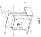
- FIG. 3is a perspective view of a microwave applicator suitable for mounting on the print carriage of FIG. 2 .
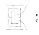
- FIGS. 4A-4Bare plan views of different dual slot configurations of microwave applicators.
- FIG. 5is a cross sectional view of a microwave applicator suitable for mounting on the print carriage of FIG. 2 .
- FIG. 6is a cross sectional view of a microwave applicator positioned proximate to a substantially conductive printer platen.
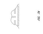
- FIGS. 7A-7Care cross sectional views of different dual slot configurations of microwave applicators.
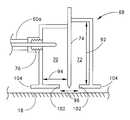
- FIG. 8is a cross sectional view of a microwave applicator positioned proximate to a substantially conductive printer platen.
- FIG. 9is a top view of another printer embodiment having a platen incorporating a series of stationary microwave slot antennas.
- one specific embodiment of a large format ink jet printer 10includes left and right side housings 11 , 12 , and is supported by a pair of legs 14 .
- the right housing 11shown in FIG. 1 with a display and keypad for operator input and control, encloses various electrical and mechanical components related to the operation of the printer device, but not directly pertinent to the present invention.
- the left housing 12encloses ink reservoirs 36 which feed ink to the ink-jet cartridges 26 via plastic conduits 38 , which run between each ink-jet cartridge 26 and each ink reservoir 36 .
- no separate ink reservoirs 36 or tubing 38is provided, and printing is performed with ink reservoirs integral to the cartridges.
- Either a roll of continuous print media(not shown) is mounted to a roller on the rear of the printer 10 to enable a continuous supply of paper to be provided to the printer 10 or individual sheets of paper (not shown) are fed into the printer 10 .
- a platen 18forms a horizontal surface which supports the print media, and printing is performed by select deposition of ink droplets onto the paper.
- a continuous supply of paperis guided from the roll of paper mounted to the rear of the printer 10 across the platen 18 by a plurality of upper rollers (not shown) which are spaced along the platen 18 .
- single sheets of paper or other print mediaare guided across the platen 18 by the rollers (not shown).
- a support structure 20is suspended above the platen 18 and spans its length with sufficient clearance between the platen 18 and the support structure to enable a sheet of paper or other print media which is to be printed on to pass between the platen 18 and the support structure 20 .
- the support structure 20supports a print carriage 22 above the platen 18 .
- the print carriage 22includes a plurality of ink-jet cartridge holders 24 , each with a replaceable ink-jet cartridge 26 mounted therein. In a preferred embodiment, four print cartridges 26 are mounted in the holders 24 on the print carriage 22 , although it is contemplated that any number ink-jet cartridges 26 may be provided.
- the support structure 20generally comprises a guide rod 30 positioned parallel to the platen 18 .
- the print carriage 22preferably comprises split sleeves which slidably engage the guide rod 30 to enable motion of the print carriage along the guide rod 30 to define a linear printing path, as shown by the bidirectional arrow 32 , along which the print carriage 22 moves.
- a motor and a drive belt mechanism(not shown) are used to drive the print carriage 22 along the guide rod 30 .
- the carriage 24passes back and forth over the media.
- the ink jet cartridges 26deposit a swath of ink having a width approximately equal to the width of the ink jet nozzle array of the jet plate on the bottom of the cartridge.
- the mediais incremented, and the carriage is passed back over the media to print the next swath.
- the ink jet cartridgescould print during passes in only one or both directions.
- the ink jet cartridgesmay pass over the same location of the media more than once.
- FIG. 2an ink jet printer incorporating a movable print carriage 44 constructed in accordance with one embodiment of the invention is shown.
- the print carriage 44is mounted on a guide rod 30 and moves back and forth in the direction of arrows 32 over a platen 18 . Between the platen 18 and the carriage 44 is the media 46 being printed.
- the carriagemounts one or more ink applicators 48 , which, for example, may comprise the four ink jet cartridges illustrated in FIG. 1, although any type of ink applicator device or method may be used in conjunction with the invention.
- microwave energy applicators 50 , 52are also attached to the carriage 44 .
- the microwave energy applicators 50 , 52are provided on opposite sides of the ink applicator 48 .
- the microwave energy applicators 50 , 52are coupled to a microwave energy source 56 , which may be mounted within one or both of the end housings (FIG. 1 ).
- the microwave energy source 56may, for example, be a magnetron of conventional design having an output center frequency at approximately 2.45 GHz.
- the microwave energy source 56may also advantageously include a means for phase shifting the microwaves to optimize coupling of the microwave applicator to the print media such as a three-stub tuner.
- the microwave energy source 56may be mounted on the carriage 44 , rather than in an end housing.
- a DC power supplymay be provided in one or both of the end housings to supply power to a carriage mounted microwave energy source.
- the microwave energy source 56is connected to the microwave applicators with commercially available coaxial cables 60 a , 60 b having a construction suitable for microwave transmission. It will be appreciated that the microwave energy source 56 may comprise a single magnetron or a plurality of magnetrons. In one embodiment, each microwave applicator 50 , 52 is separately coupled to a dedicated magnetron. In another embodiment, a single magnetron is connected to both microwave applicators 50 , 52 via a splitter mounted in the printer housing or on the print carriage 44 . As will be explained further below, each microwave energy applicator 50 , 52 generates a region 64 , 66 of microwave frequency oscillating electric fields in and through the media 46 . These electric fields heat the media 46 and the ink deposited thereon, thereby increasing the ink drying rate dramatically.
- the microwave applicator 52 on the right of the ink applicatorpasses over the droplets just deposited by the ink applicator.
- absorption of the microwave energy by the inkheats and dries the deposited droplets.
- the microwave applicator 50 on the leftis passing over and drying the just deposited ink droplets.
- the microwave applicator which is leading the ink applicator across the mediamay either be turned off, may be used to heat the media prior to printing, or may complete the drying of ink deposited on a previous pass, thereby further enhancing the ink drying process.
- the two microwave applicator embodiment shown in FIG. 2is advantageous in printers which print bidirectionally, which the vast majority of high quality color ink jet printers do. Of course, if the printer only deposits ink when the carriage is moving in one of the two directions across the media, only one microwave applicator may be necessary.
- the microwave applicatorwould be positioned relative to the ink applicator 48 such that the microwave applicator trails the ink applicator across the media as the ink applicator deposits droplets of ink. Even during unidirectional printing, however, it may be useful to pre-heat the media or complete the drying process with a second leading applicator as described above with respect to the bidirectional printer embodiment. Alternatively, both applicators can be simultaneously heating to modulate the drying process. For example, banding would be minimized with this invention.
- FIG. 3is a perspective view of a microwave applicator according to one embodiment of the invention which is suitable for mounting on the movable print carriage 44 illustrated in FIG. 2 .
- This embodiment of microwave applicator 68comprises a first chamber 70 and a second chamber 72 .
- the first chamber 70 and the second chamber 72are separated by a central plate 74 .
- the first chamber 70is a wave launching cavity and is provided with a coupler 76 for the coaxial cable which feeds the microwave energy to the applicator 68 .
- the second chamber 72is an impedance matching cavity that reflects microwave energy back to the wave launching cavity 70 .
- a bottom plate 80is also provided that forms a slot antenna on the bottom surface of the applicator 68 and which provides a path for transfer of microwave energy back and forth between the two cavities 70 , 72 .
- the bottom plate 80may also form a mounting bracket 82 for affixing the microwave energy applicator 68 to the movable print carriage of the printer.
- FIGS. 4A and 4Billustrate the bottom surface of the applicator 68 and show two embodiments of a slot antenna configuration of the microwave energy applicator 68 .
- a rectangular opening 86 in the bottom plateis approximately bisected by the central plate 74 .
- a “butterfly” shaped opening 90is approximately bisected by the central plate 74 .
- a dual slot configurationis formed, with one half of the opening 86 , 90 being coupled to the wave launching cavity 70 and the other half of the opening 86 , 90 being coupled to the impedance matching cavity 72 and being separated from one another by the central plate 74 .
- slot antenna designhas been found to be especially advantageous, other microwave antenna shapes can also be used. Examples of such other shapes are circular antenna, cross antenna and horn antenna. Many others are known to those of ordinary skill in the art and can be used in this application.
- FIG. 5illustrates a cross section along lines 5 — 5 of FIGS. 3 of one embodiment of microwave applicator 68 , showing the central plate 74 which separates the wave launching cavity 70 from the impedance matching cavity 72 .
- the central plate 74is advantageously tapered at its lower end.
- the wave launching cavityincludes a coupler 76 for receiving a coaxial cable 60 a driven by the microwave energy source (not shown).
- the print carriagemoves back and forth into and out of the plane of FIG. 5, depositing a swath of ink which is parallel to the length of the dual slot 86 in the bottom surface of the applicator 68 .
- the applicatorcould be configured to move in any desired direction over the media surface.
- the parallel slotscan be oriented at an angle with respect to the direction of printer travel, to cover a print surface width that can be as wide as the slot length.
- the dimensions of the cavitiesare as follows.
- the wave launching cavity 70advantageously has an inside cross section approximately that of WR284 waveguide with a broad dimension of about 3 ⁇ 5 ⁇ and a small dimension 94 of about 1 ⁇ 4 ⁇ , where ⁇ is the wavelength emitted by the center frequency of the microwave energy source, which is approximately 4.75 inches for 2.45 GHz microwaves.
- the wave launching cavityhas an inside rectangular (horizontal) cross section of about 2.84 inches by 1.34 inches.
- the dimensions of the wave launching cavity and the positioning of the coupler 76are determined by well known microwave principles of wave launching.
- the cross section of the impedance matching cavity 72may be approximately the same as the wave launching cavity 70 .
- the height of the impedance matching cavityis preferably an odd multiple of 1 ⁇ 4 ⁇ .
- the height 92can be approximately 3 ⁇ 4 ⁇ .
- the combined width 96 of the dual slotis advantageously slightly greater than the width of a swath of being printed, so that all of the ink deposited in a swath is approximately centrally located beneath the slots.
- the length of the slotsis about 3 inches, and the width 96 of the dual slot is about 1 ⁇ 2 inches.
- the edges 102 of the rectangular opening 86 in the bottom plate 80are preferably about 1 ⁇ 4 ⁇ from the outer edges 104 of the bottom plate 80 .
- the space between the bottom plate 80 and the electrically conductive platen 18acts as a choke to confine the microwaves to that region. Additional protection from microwave leakage may be obtained by covering the outer surfaces of the applicator with a microwave absorbing material such as Ecosorb FGM-125 which is available from GAE engineering of Modesto, Calif.
- a Holaday microwave detectorthe leakage for the system was under 1 mw/cm 2 at 2.45 GHz at a distance of 2 feet from the applicator mounted on the movable print carriage. Radio frequency leakage management can be achieved with this design and variations of the design suitable for a wide range of ink jet printer applications including desk top sized ink jet printers.
- FIG. 6The general configuration of these electric fields is shown in FIG. 6 .
- This Figureis a close up of the dual slot 86 in the cross section of FIG. 5 .
- Electric field strengths at various locations in the dual slot regionare illustrated by arrows 98 , where a longer arrow 98 indicates a larger electric field strength and the arrow 98 direction indicates the electric field direction.
- the electric field intensityis strongest in the region near and beneath the central plate, and is oriented substantially vertically in this region. Away from the center, the intensity drops off, and the electric field intensity has a larger horizontal component.
- the electric fieldbecomes more vertically oriented closer to the platen surface of the substantially conductive platen 18 . It is preferable to have the bottom plate 80 separated from the electrically conductive platen 18 by a distance of about 0.2 inches.
- the wavesare then reflected from the top electrically conductive plate of the impedance matching cavity 72 and then are radiated by the second slot to pass through the printed media a third time.
- the waveis guided by the boundaries between the bottom plate 80 and the electrically conducting platen 18 and go through the printed media a fourth time while being absorbed by the slot in the wave launching cavity.
- a fraction of the power reabsorbed in the wave launching cavityis then reflected again to make another multiple set of penetrations through the media.
- the weight of the microwave applicator as described aboveis less than 1 pound when the microwave energy source is mounted in one of the end housings.
- the total weight of applicator plus microwave energy sourceis less than 3 pounds when a magnetron energy source is used.
- the total weight of applicator plus microwave energy sourcecan be less than 1.5 pounds. Low weight is beneficial to the process of moving the microwave applicator with the print carriage.
- the central plate 74may have a flat bottom edge, rather than being tapered.
- the central plate 74may extend downward through the dual slot beneath the bottom plate of the applicator 68 .
- the plate 74is configured as a wedge.
- the bottom plates of the cavities 70 , 72may be tapered to follow the wedge shape of the central plate 74 , or they may be flat plates as shown in FIGS. 7A and 7B.
- FIG. 8shows a cross section of a microwave applicator in proximity to a platen 18 , and also shows a sheet of media 106 beneath the applicator 68 .
- the media 106is supported above the platen 18 surface by a layer of material which covers the platen 18 .
- This layer of materialmaintains the media in the region of electric fields containing relatively strong horizontal components as discussed above with reference to FIG. 6 .
- the layercomprises three different types of material.
- the materialcomprises a dielectric polymer material that is substantially transparent to the microwave energy. Many common plastics such as PTFE, glass reinforced nylon, or others are suitable.
- the materialcomprises a microwave absorbing material such as Ecosorb FGM-125 which is available from GAE engineering of Modesto Calif.
- the presence of microwave absorbing material on the periphery of the dual slotfurther reduces microwave leakage beyond the perimeter of the applicator 68 , and also heats the media prior to printing the next swath, and after printing the last swath, which can further improve ink drying characteristics of the system.
- the distance 112 between the platen 18 and the bottom of the applicator 68is approximately 0.2 inches
- the thickness 114 of the layeris approximately 0.1 inches.
- FIG. 9Another alternative embodiment of the invention is illustrated in FIG. 9 .
- microwave applicatorsare stationary, rather than being affixed to the movable print carriage.
- FIG. 9shows a top view of a platen 18 having a series of dual slots 120 formed therein. Each dual slot 120 is coupled to a wave launching and impedance matching cavity as described above but mounted beneath the platen 18 .
- a series of microwave applicatorsextend along the platen beneath the printed swaths of ink.
- the carriage 44is provided with two substantially conductive plates, 122 A, 122 B extending from each side. These metal plates 122 A, 122 B are positioned just above the platen 18 surface.
- the ink applicator 48deposits a swath of ink.
- the trailing plate 122 Bpasses over each dual slot, the corresponding microwave applicator is activated, thereby drying the ink between that dual slot and the plate 122 B. Ink deposition and drying in the rightward direction proceeds in an analogous fashion, but the trailing plate is now plate 122 A.
- microwave ink drying apparatus and methodsprovide many advantages over previously known systems. Wasted energy due to reflections back to the source are minimized. Furthermore, all the ink is exposed to substantially the same intensity of electric fields, making the drying process more even.
- realization of uniformity of heating or drying with microwave applicators with intense electric field regionshas been impractical because of the difficulty in arranging such intense electric field region applicators in a uniform manner over the printed media or web. Moving the microwave applicator with the ink jet print head eliminates the geometrical non-uniformity issue. The print surface is always exposed to substantially the same electric fields during drying. In addition, drying occurs as the ink is deposited, rather than after the image is complete, thereby improving the effectiveness of multi-pass printing techniques.
- reflected powercan be measured, and and microwave power can be dynamically adjusted to compensate for variations in deposited ink density, further improving the consistency of ink drying across the entire image.
- microwave powercan be adjusted on time scales of microseconds.
- a sensor located in the tunercan sense the signal reflected from the applicator and adjust the power level depending on the ink coverage. For example, if no ink is being deposited the power can be kept at low level.
- the signals being used to control the ink jet printing processcould be used to control the amount of microwave power being applied. i.e. if the ink jets are instructed to print at 100% coverage the signal can also maintain the microwaves at the appropriate power.
- microwave powercan be controlled and synchronized with the ink-media system to modulate the cure process. This is useful for color management and to minimize banding.
- the temperature rise rate of water soaked paper placed proximate to the slotwas measured using a Cole-Parmer infrared thermal probe. At a net microwave power of 60 watts, the temperature rise was 198° C. in a time period of between one and two seconds. This is a heating rate of 1.6° C./second-watt. In 2 seconds, the paper was observed to char.
- a dual slot applicator 68 as described abovewas used to dry ENCAD 600 dpi GO-Cyan printed on plain paper with 100% coverage with an ink jet printer.
- the bottom plate 80comprised 2 parallel slots, each about 3 inches long and 1 ⁇ 8 inch in width, separated by about 1 ⁇ 8′′.
- a styrofoam layer about 1 ⁇ 8′′ thickwas placed on the electrically conducting platen 18 and the bottom plate 80 was located 0.04 inches above the printed paper. The total separation between the bottom plate 80 and the electrically conducting platen was about 0.2 inches.
- Inks which sublimate when heatedcan be printed on textiles. Typically, they are printed and then passed through an infrared oven or hot air dryer where the temperature is raised to about 400° F., whereupon the dye is sublimated and is fixed to the textile.
- Sublijet blue dye sublimation ink from Sawgrass Corporationwas printed on a white polyester using an ink jet printer and was exposed to a dual slot microwave energy from applicator for a period of 2 seconds at 200 watts. The textile was subsequently washed. The result was that each of the two slots had fixed the dye along the entire length of the slot.
- Drying ink jet printed ink on non-porous and uncoated vinyl sheetis desirable, but difficult because the ink can form beads and move on the surface. Immediate drying with microwaves can stop the movement of the ink and dry it on an untreated vinyl surface.
- ENCAD experimental GO-magenta inkwas printed on untreated sheet vinyl and exposed to the microwave energy from a dual slot microwave energy applicator. With exposure at 200 watts for 4 seconds the ink adhered.
- the inventionis shown to solve two of the major problems associated with drying of ink on print media.
- uniformity of electric field geometryis provided by moving the applicator over the surface.
- multiple passes of the microwaves through the mediacan lead to an absorption efficiency close to 100 percent for all levels of ink coverage whether the coverage is light or heavy.
- the power levelcan be adjusted to match the ink loading.
- Some ink jet printersdo not have an electrically conductive platen.
- the paperis supported by thin plastic supports while the printer carriage moves across the paper.
- the spacecould be filled with a ceramic or dielectric material.
- the moving microwave energy applicator concept of this inventioncan be adapted to this situation.
- the electric field patterns near the slot antennawould still be intense. Removal of the electrically conducting platen 18 in FIG. 6 would not influence the directions and magnitude of the electric fields near the print media surface when the print media surface is proximate to the print media. With proper impedance matching, the multiple passes of microwave energy through the media would also take place.
- An electrically conductive surfacemay be included to help prevent microwave leakage and could be incorporated in the box containing the printer.
- the drying of ink jet ink deposited on a paper mediais one useful application.
- the sharpness of individual ink dotscan be maintained by preventing spreading of the dot in the media. Coalescence of adjacent dots can be prevented by drying before they coalesce. Microwave drying between passes can be used to dry or partially dry one ensemble of dots before a second ensemble is applied, minimizing coalescence of the second set of dots with the first set.
- the shape of individual dotscan be maintained by drying them before their shape can be changed by contact with other dots or by wetting the fibers of the media. Most importantly the speed of drying and the quality of printing multiple passes can be greatly improved.
- the aqueous liquid vehicle in thermal ink jet printingcan create quality problems if not substantially removed from the media. For example, if the sheet is covered with more than 50% printing, and the liquid is not removed quickly, then defects in the image, such as strike through, and paper deformation such as cockle can result.
- the present inventioncan minimize such problems by removing the liquid essentially immediately after printing. Use of this invention can permit use of inexpensive printing paper, because special coatings will not be needed to provide absorption of the liquid in the ink.
- Substrates such as uncoated vinylcan be printed on with an ink jet printer without regard to surface tension.
- the electric field intensity in the slotscould be raised to produce a controlled electrical breakdown plasma in the air directly over the surface of the vinyl to produce plasma activation of the surface molecules.
- Such surface modificationscould improve the adhesion of ink on the vinyl surface.
- Another application of such a continuous breakdown sourcewould be to sterilize surfaces of materials.
- the microwave applicatorcould be mounted on a moveable assembly and moved in a computer controlled system across say, a wooden surface and woodburning or texturing of the surface could be accomplished with microwave heating.
- the properties of laminated ink jet productcan also be improved with this invention. For example, by removing substantially all the liquid from the ink and media prior to lamination, one can increase the UV resistance and color stability versus time.
- ink jet solid imagingin which a printer similar to an ink jet printer moves around a platform and, by projecting microdots of plastic to produce solid objects, could also benefit by an instant solidification via a microwave applicator that travels with the ink jet printer.
- an ink jet printercould make toys or other useful objects by downloading patterns from the internet.
Landscapes
- Engineering & Computer Science (AREA)
- Health & Medical Sciences (AREA)
- General Health & Medical Sciences (AREA)
- Toxicology (AREA)
- Electromagnetism (AREA)
- Mechanical Engineering (AREA)
- General Engineering & Computer Science (AREA)
- Physics & Mathematics (AREA)
- Life Sciences & Earth Sciences (AREA)
- Microbiology (AREA)
- Textile Engineering (AREA)
- Biomedical Technology (AREA)
- Biotechnology (AREA)
- Molecular Biology (AREA)
- Ink Jet (AREA)
Abstract
Description
Claims (8)
Priority Applications (5)
| Application Number | Priority Date | Filing Date | Title |
|---|---|---|---|
| US09/579,856US6508550B1 (en) | 2000-05-25 | 2000-05-25 | Microwave energy ink drying method |
| PCT/US2001/040802WO2001089835A2 (en) | 2000-05-25 | 2001-05-25 | Microwave energy ink drying system and method |
| JP2001586053AJP2003534164A (en) | 2000-05-25 | 2001-05-25 | Microwave energy ink drying system and method |
| EP01939940AEP1283780A2 (en) | 2000-05-25 | 2001-05-25 | Microwave energy ink drying system and method |
| AU2001265404AAU2001265404A1 (en) | 2000-05-25 | 2001-05-25 | Microwave energy ink drying system and method |
Applications Claiming Priority (1)
| Application Number | Priority Date | Filing Date | Title |
|---|---|---|---|
| US09/579,856US6508550B1 (en) | 2000-05-25 | 2000-05-25 | Microwave energy ink drying method |
Publications (1)
| Publication Number | Publication Date |
|---|---|
| US6508550B1true US6508550B1 (en) | 2003-01-21 |
Family
ID=24318627
Family Applications (1)
| Application Number | Title | Priority Date | Filing Date |
|---|---|---|---|
| US09/579,856Expired - Fee RelatedUS6508550B1 (en) | 2000-05-25 | 2000-05-25 | Microwave energy ink drying method |
Country Status (1)
| Country | Link |
|---|---|
| US (1) | US6508550B1 (en) |
Cited By (23)
| Publication number | Priority date | Publication date | Assignee | Title |
|---|---|---|---|---|
| US20050004263A1 (en)* | 2003-07-02 | 2005-01-06 | Ilford Imaging Uk Limited | Ink jet ink and recording process |
| US20050024459A1 (en)* | 2001-08-30 | 2005-02-03 | Codos Richard N. | Method and apparatus for ink jet printing on rigid panels |
| US20050118253A1 (en)* | 1998-02-03 | 2005-06-02 | Protiva Biotherapeutics, Inc. | Systemic delivery of serum stable plasmid lipid particles for cancer therapy |
| US20060009021A1 (en)* | 2004-07-06 | 2006-01-12 | Herman Gregory S | Structure formation |
| WO2007038950A1 (en) | 2005-09-28 | 2007-04-12 | Stichting Dutch Polymer Institute | Method for generation of metal surface structures and apparatus therefor |
| US20070079719A1 (en)* | 2005-06-30 | 2007-04-12 | Domingo Rohde | Ink jet printing and drying a printing material |
| US20080155765A1 (en)* | 2006-12-28 | 2008-07-03 | Kimberly-Clark Worldwide, Inc. | Process for dyeing a textile web |
| US20080156427A1 (en)* | 2006-12-28 | 2008-07-03 | Kimberly-Clark Worldwide, Inc. | Process For Bonding Substrates With Improved Microwave Absorbing Compositions |
| US20090160925A1 (en)* | 2007-12-25 | 2009-06-25 | Seiko Epson Corporation | Recording apparatus and method for heating recording medium |
| US20090184987A1 (en)* | 2008-01-21 | 2009-07-23 | Seiko Epson Corporation | Recording apparatus in which recording medium is heated and method for the same |
| US7568251B2 (en) | 2006-12-28 | 2009-08-04 | Kimberly-Clark Worldwide, Inc. | Process for dyeing a textile web |
| US20090322843A1 (en)* | 2008-06-25 | 2009-12-31 | Mimaki Engineering Co., Ltd. | Inkjet printer and ink dryer |
| EP2194764A1 (en)* | 2008-12-04 | 2010-06-09 | Stichting Dutch Polymer Institute | Method for generation of electrically conducting surface structures, apparatus therefor and use |
| US7740666B2 (en) | 2006-12-28 | 2010-06-22 | Kimberly-Clark Worldwide, Inc. | Process for dyeing a textile web |
| US20110115864A1 (en)* | 2008-07-31 | 2011-05-19 | Domingo Rohde | Method for drying a printing substrate and/or a printing medium located thereon and a printing machine |
| WO2011101150A1 (en)* | 2010-02-17 | 2011-08-25 | Dieffenbacher System-Automation Gmbh | Device and method for printing surfaces of material panels, especially wood panels, with a multi-colour image |
| US20120051000A1 (en)* | 2010-08-31 | 2012-03-01 | Viasat, Inc. | Leadframe package with integrated partial waveguide interface |
| US8182552B2 (en) | 2006-12-28 | 2012-05-22 | Kimberly-Clark Worldwide, Inc. | Process for dyeing a textile web |
| US20120301122A1 (en)* | 2011-05-23 | 2012-11-29 | Ocean Net Inc. | Dye sublimation heating module and system thereof |
| US8632613B2 (en) | 2007-12-27 | 2014-01-21 | Kimberly-Clark Worldwide, Inc. | Process for applying one or more treatment agents to a textile web |
| US8807736B1 (en) | 2013-01-31 | 2014-08-19 | Ricoh Company, Ltd. | Low-temperature gas flow insertion in printing system dryers |
| US8872333B2 (en) | 2008-02-14 | 2014-10-28 | Viasat, Inc. | System and method for integrated waveguide packaging |
| US8899150B2 (en)* | 2012-11-01 | 2014-12-02 | Ricoh Company, Ltd. | Reduction of print head temperature by disrupting air from heated webs of print media |
Citations (30)
| Publication number | Priority date | Publication date | Assignee | Title |
|---|---|---|---|---|
| US3705283A (en) | 1971-08-16 | 1972-12-05 | Varian Associates | Microwave applicator employing a broadside slot radiator |
| US3851132A (en) | 1973-12-10 | 1974-11-26 | Canadian Patents Dev | Parallel plate microwave applicator |
| US3999026A (en) | 1974-02-22 | 1976-12-21 | Stiftelsen Institutet For Mikrovagsteknik Vid Teknishka Hogskolan I Stockholm | Heating device fed with microwave energy |
| US4160144A (en) | 1978-01-25 | 1979-07-03 | Canadian Patents And Development Limited | Single-sided microwave applicator for sealing cartons |
| US4234775A (en) | 1978-08-17 | 1980-11-18 | Technical Developments, Inc. | Microwave drying for continuously moving webs |
| US4392039A (en) | 1980-01-21 | 1983-07-05 | P.O.R. Microtrans Ab | Dielectric heating applicator |
| US4476363A (en) | 1980-01-03 | 1984-10-09 | Stiftelsen Institutet For Mikrovagsteknik Vid Tekniska Hogskolan I Stockholm | Method and device for heating by microwave energy |
| US4482239A (en) | 1981-04-25 | 1984-11-13 | Canon Kabushiki Kaisha | Image recorder with microwave fixation |
| US4625088A (en) | 1985-11-07 | 1986-11-25 | Gics Paul W | Center wall with sloped ends for a microwave heat applicator |
| US5041846A (en)* | 1988-12-16 | 1991-08-20 | Hewlett-Packard Company | Heater assembly for printers |
| US5220346A (en) | 1992-02-03 | 1993-06-15 | Xerox Corporation | Printing processes with microwave drying |
| EP0555968A1 (en) | 1992-02-14 | 1993-08-18 | Lucas Industries Public Limited Company | Optical device and a method of manufacture thereof |
| EP0559324A1 (en) | 1992-02-03 | 1993-09-08 | Xerox Corporation | Ink jet printing processes with microwave drying |
| US5278375A (en) | 1990-03-07 | 1994-01-11 | Microondes Energie Systemes | Microwave applicator device for the treatment of sheet or lap products |
| US5349905A (en) | 1992-03-24 | 1994-09-27 | Xerox Corporation | Method and apparatus for controlling peak power requirements of a printer |
| US5371531A (en) | 1992-11-12 | 1994-12-06 | Xerox Corporation | Thermal ink-jet printing with fast- and slow-drying inks |
| US5423260A (en) | 1993-09-22 | 1995-06-13 | Rockwell International Corporation | Device for heating a printed web for a printing press |
| JPH07314661A (en) | 1994-05-27 | 1995-12-05 | Canon Inc | Inkjet recording method and recording apparatus |
| US5536921A (en) | 1994-02-15 | 1996-07-16 | International Business Machines Corporation | System for applying microware energy in processing sheet like materials |
| US5566344A (en) | 1994-12-20 | 1996-10-15 | National Semiconductor Corporation | In-system programming architecture for a multiple chip processor |
| US5631685A (en) | 1993-11-30 | 1997-05-20 | Xerox Corporation | Apparatus and method for drying ink deposited by ink jet printing |
| US5709737A (en) | 1996-02-20 | 1998-01-20 | Xerox Corporation | Ink jet inks and printing processes |
| US5712672A (en) | 1995-04-03 | 1998-01-27 | Xerox Corporation | Recording sheet transport and effluents removal system |
| US5764263A (en) | 1996-02-05 | 1998-06-09 | Xerox Corporation | Printing process, apparatus, and materials for the reduction of paper curl |
| US5814138A (en) | 1997-01-24 | 1998-09-29 | Xerox Corporation | Microwave dryable thermal ink jet inks |
| US5853469A (en) | 1997-07-31 | 1998-12-29 | Xerox Corporation | Ink compositions for ink jet printing |
| US6020580A (en) | 1997-01-06 | 2000-02-01 | International Business Machines Corporation | Microwave applicator having a mechanical means for tuning |
| US6022104A (en) | 1997-05-02 | 2000-02-08 | Xerox Corporation | Method and apparatus for reducing intercolor bleeding in ink jet printing |
| US6208903B1 (en)* | 1995-06-07 | 2001-03-27 | Medical Contouring Corporation | Microwave applicator |
| US6231176B1 (en)* | 1999-10-04 | 2001-05-15 | Xerox Corporation | Self-tensioning flexible heater assembly for drying image bearing substrates in an ink jet printer |
- 2000
- 2000-05-25USUS09/579,856patent/US6508550B1/ennot_activeExpired - Fee Related
Patent Citations (33)
| Publication number | Priority date | Publication date | Assignee | Title |
|---|---|---|---|---|
| US3705283A (en) | 1971-08-16 | 1972-12-05 | Varian Associates | Microwave applicator employing a broadside slot radiator |
| US3851132A (en) | 1973-12-10 | 1974-11-26 | Canadian Patents Dev | Parallel plate microwave applicator |
| US3999026A (en) | 1974-02-22 | 1976-12-21 | Stiftelsen Institutet For Mikrovagsteknik Vid Teknishka Hogskolan I Stockholm | Heating device fed with microwave energy |
| US4160144A (en) | 1978-01-25 | 1979-07-03 | Canadian Patents And Development Limited | Single-sided microwave applicator for sealing cartons |
| US4234775A (en) | 1978-08-17 | 1980-11-18 | Technical Developments, Inc. | Microwave drying for continuously moving webs |
| US4476363A (en) | 1980-01-03 | 1984-10-09 | Stiftelsen Institutet For Mikrovagsteknik Vid Tekniska Hogskolan I Stockholm | Method and device for heating by microwave energy |
| US4392039A (en) | 1980-01-21 | 1983-07-05 | P.O.R. Microtrans Ab | Dielectric heating applicator |
| US4482239A (en) | 1981-04-25 | 1984-11-13 | Canon Kabushiki Kaisha | Image recorder with microwave fixation |
| US4625088A (en) | 1985-11-07 | 1986-11-25 | Gics Paul W | Center wall with sloped ends for a microwave heat applicator |
| US5041846A (en)* | 1988-12-16 | 1991-08-20 | Hewlett-Packard Company | Heater assembly for printers |
| US5278375A (en) | 1990-03-07 | 1994-01-11 | Microondes Energie Systemes | Microwave applicator device for the treatment of sheet or lap products |
| US5220346A (en) | 1992-02-03 | 1993-06-15 | Xerox Corporation | Printing processes with microwave drying |
| EP0559324A1 (en) | 1992-02-03 | 1993-09-08 | Xerox Corporation | Ink jet printing processes with microwave drying |
| US5563644A (en) | 1992-02-03 | 1996-10-08 | Xerox Corporation | Ink jet printing processes with microwave drying |
| EP0559324B1 (en) | 1992-02-03 | 1995-10-18 | Xerox Corporation | Ink jet printing processes with microwave drying |
| EP0555968A1 (en) | 1992-02-14 | 1993-08-18 | Lucas Industries Public Limited Company | Optical device and a method of manufacture thereof |
| EP0555968B1 (en) | 1992-02-14 | 1997-07-09 | Lucas Industries Public Limited Company | Optical device and a method of manufacture thereof |
| US5349905A (en) | 1992-03-24 | 1994-09-27 | Xerox Corporation | Method and apparatus for controlling peak power requirements of a printer |
| US5371531A (en) | 1992-11-12 | 1994-12-06 | Xerox Corporation | Thermal ink-jet printing with fast- and slow-drying inks |
| US5423260A (en) | 1993-09-22 | 1995-06-13 | Rockwell International Corporation | Device for heating a printed web for a printing press |
| US5631685A (en) | 1993-11-30 | 1997-05-20 | Xerox Corporation | Apparatus and method for drying ink deposited by ink jet printing |
| US5536921A (en) | 1994-02-15 | 1996-07-16 | International Business Machines Corporation | System for applying microware energy in processing sheet like materials |
| JPH07314661A (en) | 1994-05-27 | 1995-12-05 | Canon Inc | Inkjet recording method and recording apparatus |
| US5566344A (en) | 1994-12-20 | 1996-10-15 | National Semiconductor Corporation | In-system programming architecture for a multiple chip processor |
| US5712672A (en) | 1995-04-03 | 1998-01-27 | Xerox Corporation | Recording sheet transport and effluents removal system |
| US6208903B1 (en)* | 1995-06-07 | 2001-03-27 | Medical Contouring Corporation | Microwave applicator |
| US5764263A (en) | 1996-02-05 | 1998-06-09 | Xerox Corporation | Printing process, apparatus, and materials for the reduction of paper curl |
| US5709737A (en) | 1996-02-20 | 1998-01-20 | Xerox Corporation | Ink jet inks and printing processes |
| US6020580A (en) | 1997-01-06 | 2000-02-01 | International Business Machines Corporation | Microwave applicator having a mechanical means for tuning |
| US5814138A (en) | 1997-01-24 | 1998-09-29 | Xerox Corporation | Microwave dryable thermal ink jet inks |
| US6022104A (en) | 1997-05-02 | 2000-02-08 | Xerox Corporation | Method and apparatus for reducing intercolor bleeding in ink jet printing |
| US5853469A (en) | 1997-07-31 | 1998-12-29 | Xerox Corporation | Ink compositions for ink jet printing |
| US6231176B1 (en)* | 1999-10-04 | 2001-05-15 | Xerox Corporation | Self-tensioning flexible heater assembly for drying image bearing substrates in an ink jet printer |
Cited By (40)
| Publication number | Priority date | Publication date | Assignee | Title |
|---|---|---|---|---|
| US20050118253A1 (en)* | 1998-02-03 | 2005-06-02 | Protiva Biotherapeutics, Inc. | Systemic delivery of serum stable plasmid lipid particles for cancer therapy |
| US7290874B2 (en) | 2001-08-30 | 2007-11-06 | L&P Property Management Company | Method and apparatus for ink jet printing on rigid panels |
| US20050024459A1 (en)* | 2001-08-30 | 2005-02-03 | Codos Richard N. | Method and apparatus for ink jet printing on rigid panels |
| US20090225145A1 (en)* | 2001-08-30 | 2009-09-10 | L&P Property Management Company | Method and apparatus for ink jet printing on rigid panels |
| US7520602B2 (en) | 2001-08-30 | 2009-04-21 | L & P Property Management Company | Method and apparatus for ink jet printing on rigid panels |
| US20080049088A1 (en)* | 2001-08-30 | 2008-02-28 | L&P Property Management Company | Method and apparatus for ink jet printing on rigid panels |
| US20050004263A1 (en)* | 2003-07-02 | 2005-01-06 | Ilford Imaging Uk Limited | Ink jet ink and recording process |
| US8143616B2 (en) | 2004-07-06 | 2012-03-27 | Oregon State University | Making a structure |
| US20090200541A1 (en)* | 2004-07-06 | 2009-08-13 | Hewlett-Packard Development Company Lp | Making a structure |
| US7547647B2 (en) | 2004-07-06 | 2009-06-16 | Hewlett-Packard Development Company, L.P. | Method of making a structure |
| US20060009021A1 (en)* | 2004-07-06 | 2006-01-12 | Herman Gregory S | Structure formation |
| US20070079719A1 (en)* | 2005-06-30 | 2007-04-12 | Domingo Rohde | Ink jet printing and drying a printing material |
| WO2007038950A1 (en) | 2005-09-28 | 2007-04-12 | Stichting Dutch Polymer Institute | Method for generation of metal surface structures and apparatus therefor |
| US7674300B2 (en) | 2006-12-28 | 2010-03-09 | Kimberly-Clark Worldwide, Inc. | Process for dyeing a textile web |
| US7740666B2 (en) | 2006-12-28 | 2010-06-22 | Kimberly-Clark Worldwide, Inc. | Process for dyeing a textile web |
| US20080155765A1 (en)* | 2006-12-28 | 2008-07-03 | Kimberly-Clark Worldwide, Inc. | Process for dyeing a textile web |
| US8182552B2 (en) | 2006-12-28 | 2012-05-22 | Kimberly-Clark Worldwide, Inc. | Process for dyeing a textile web |
| US7568251B2 (en) | 2006-12-28 | 2009-08-04 | Kimberly-Clark Worldwide, Inc. | Process for dyeing a textile web |
| US20080156427A1 (en)* | 2006-12-28 | 2008-07-03 | Kimberly-Clark Worldwide, Inc. | Process For Bonding Substrates With Improved Microwave Absorbing Compositions |
| US20090160925A1 (en)* | 2007-12-25 | 2009-06-25 | Seiko Epson Corporation | Recording apparatus and method for heating recording medium |
| US8287115B2 (en)* | 2007-12-25 | 2012-10-16 | Seiko Epson Corporation | Recording apparatus and method for heating recording medium |
| US8632613B2 (en) | 2007-12-27 | 2014-01-21 | Kimberly-Clark Worldwide, Inc. | Process for applying one or more treatment agents to a textile web |
| US20090184987A1 (en)* | 2008-01-21 | 2009-07-23 | Seiko Epson Corporation | Recording apparatus in which recording medium is heated and method for the same |
| US8872333B2 (en) | 2008-02-14 | 2014-10-28 | Viasat, Inc. | System and method for integrated waveguide packaging |
| US20090322843A1 (en)* | 2008-06-25 | 2009-12-31 | Mimaki Engineering Co., Ltd. | Inkjet printer and ink dryer |
| US8136935B2 (en)* | 2008-06-25 | 2012-03-20 | Mimaki Engineering Co., Ltd. | Inkjet printer and ink dryer |
| US20110115864A1 (en)* | 2008-07-31 | 2011-05-19 | Domingo Rohde | Method for drying a printing substrate and/or a printing medium located thereon and a printing machine |
| WO2010063481A1 (en)* | 2008-12-04 | 2010-06-10 | Stichting Dutch Polymer Institute | Method for generation of electrically conducting surface structures, apparatus therefor and use |
| EP2194764A1 (en)* | 2008-12-04 | 2010-06-09 | Stichting Dutch Polymer Institute | Method for generation of electrically conducting surface structures, apparatus therefor and use |
| WO2011101150A1 (en)* | 2010-02-17 | 2011-08-25 | Dieffenbacher System-Automation Gmbh | Device and method for printing surfaces of material panels, especially wood panels, with a multi-colour image |
| US20120051000A1 (en)* | 2010-08-31 | 2012-03-01 | Viasat, Inc. | Leadframe package with integrated partial waveguide interface |
| US8592960B2 (en)* | 2010-08-31 | 2013-11-26 | Viasat, Inc. | Leadframe package with integrated partial waveguide interface |
| US20140183710A1 (en)* | 2010-08-31 | 2014-07-03 | Viasat, Inc. | Leadframe package with integrated partial waveguide interface |
| US9142492B2 (en)* | 2010-08-31 | 2015-09-22 | Viasat, Inc. | Leadframe package with integrated partial waveguide interface |
| US20160050793A1 (en)* | 2010-08-31 | 2016-02-18 | Viasat, Inc. | Leadframe package with integrated partial waveguide interface |
| US9426929B2 (en)* | 2010-08-31 | 2016-08-23 | Viasat, Inc. | Leadframe package with integrated partial waveguide interface |
| US20120301122A1 (en)* | 2011-05-23 | 2012-11-29 | Ocean Net Inc. | Dye sublimation heating module and system thereof |
| US8450655B2 (en)* | 2011-05-23 | 2013-05-28 | Ocean Net, Inc. | Dye sublimation heating module and system thereof |
| US8899150B2 (en)* | 2012-11-01 | 2014-12-02 | Ricoh Company, Ltd. | Reduction of print head temperature by disrupting air from heated webs of print media |
| US8807736B1 (en) | 2013-01-31 | 2014-08-19 | Ricoh Company, Ltd. | Low-temperature gas flow insertion in printing system dryers |
Similar Documents
| Publication | Publication Date | Title |
|---|---|---|
| US6425663B1 (en) | Microwave energy ink drying system | |
| US6508550B1 (en) | Microwave energy ink drying method | |
| US6444964B1 (en) | Microwave applicator for drying sheet material | |
| US5631685A (en) | Apparatus and method for drying ink deposited by ink jet printing | |
| JP7077567B2 (en) | Liquid discharge device, image formation method | |
| EP1283780A2 (en) | Microwave energy ink drying system and method | |
| US5757407A (en) | Liquid ink printer having multiple pass drying | |
| DE69303426T2 (en) | Heater screen for the print zone for thermal inkjet printers | |
| US5446487A (en) | Air evacuation system for ink-jet printer | |
| US6059406A (en) | Heater blower system in a color ink-jet printer | |
| US5287123A (en) | Preheat roller for thermal ink-jet printer | |
| US8287116B2 (en) | Printing apparatus and method | |
| US5410283A (en) | Phase shifter for fine tuning a microwave applicator | |
| EP0568181B1 (en) | Thermal ink-jet printer with print heater having variable heat energy for different media | |
| US9211727B2 (en) | Recording apparatus | |
| US6428158B1 (en) | Liquid ink printer having a heat and hold drier | |
| US20040061759A1 (en) | Curved infrared foil heater for drying images on a recording medium | |
| US6305796B1 (en) | Thermal ink jet printer having dual function dryer | |
| EP0997301A2 (en) | Infrared foil heater for drying ink jet images on a recording medium | |
| JP2006212929A (en) | Inkjet recording device | |
| US7673979B2 (en) | Ink-jet printing device including a microwave heating device | |
| JP2025043492A (en) | Dryer apparatus and recording apparatus | |
| JP2025122353A (en) | Drying device and recording device | |
| JP2025133249A (en) | Drying device and recording device | |
| JP2004042474A (en) | Inkjet recording device |
Legal Events
| Date | Code | Title | Description |
|---|---|---|---|
| AS | Assignment | Owner name:ENCAD, INC., CALIFORNIA Free format text:ASSIGNMENT OF ASSIGNORS INTEREST;ASSIGNORS:EASTLUND, BERNARD JOHN;SPANN, DONALD EMMETT;ALFEKRI, DHEYA MORTADA;REEL/FRAME:011331/0751;SIGNING DATES FROM 20001110 TO 20001120 | |
| AS | Assignment | Owner name:EASTMAN KODAK, NEW YORK Free format text:ASSIGNMENT OF ASSIGNORS INTEREST;ASSIGNOR:ENCAD, INC.;REEL/FRAME:012936/0443 Effective date:20020516 | |
| AS | Assignment | Owner name:EASTMAN KODAK, NEW YORK Free format text:ASSIGNMENT OF ASSIGNORS INTEREST;ASSIGNOR:ENCAD, INC.;REEL/FRAME:012944/0036 Effective date:20020516 | |
| FPAY | Fee payment | Year of fee payment:4 | |
| AS | Assignment | Owner name:EASTMAN KODAK COMPANY, NEW YORK Free format text:CORRECTIVE ASSIGNMENT TO CORRECT THE ASSIGNEE PREVIOUSLY RECORDED ON REEL 012944 FRAME 0036;ASSIGNOR:ENCAD, INC.;REEL/FRAME:019744/0308 Effective date:20020516 | |
| FEPP | Fee payment procedure | Free format text:PAYOR NUMBER ASSIGNED (ORIGINAL EVENT CODE: ASPN); ENTITY STATUS OF PATENT OWNER: LARGE ENTITY | |
| FPAY | Fee payment | Year of fee payment:8 | |
| AS | Assignment | Owner name:CITICORP NORTH AMERICA, INC., AS AGENT, NEW YORK Free format text:SECURITY INTEREST;ASSIGNORS:EASTMAN KODAK COMPANY;PAKON, INC.;REEL/FRAME:028201/0420 Effective date:20120215 | |
| AS | Assignment | Owner name:WILMINGTON TRUST, NATIONAL ASSOCIATION, AS AGENT, Free format text:PATENT SECURITY AGREEMENT;ASSIGNORS:EASTMAN KODAK COMPANY;PAKON, INC.;REEL/FRAME:030122/0235 Effective date:20130322 Owner name:WILMINGTON TRUST, NATIONAL ASSOCIATION, AS AGENT, MINNESOTA Free format text:PATENT SECURITY AGREEMENT;ASSIGNORS:EASTMAN KODAK COMPANY;PAKON, INC.;REEL/FRAME:030122/0235 Effective date:20130322 | |
| AS | Assignment | Owner name:BANK OF AMERICA N.A., AS AGENT, MASSACHUSETTS Free format text:INTELLECTUAL PROPERTY SECURITY AGREEMENT (ABL);ASSIGNORS:EASTMAN KODAK COMPANY;FAR EAST DEVELOPMENT LTD.;FPC INC.;AND OTHERS;REEL/FRAME:031162/0117 Effective date:20130903 Owner name:BARCLAYS BANK PLC, AS ADMINISTRATIVE AGENT, NEW YORK Free format text:INTELLECTUAL PROPERTY SECURITY AGREEMENT (SECOND LIEN);ASSIGNORS:EASTMAN KODAK COMPANY;FAR EAST DEVELOPMENT LTD.;FPC INC.;AND OTHERS;REEL/FRAME:031159/0001 Effective date:20130903 Owner name:JPMORGAN CHASE BANK, N.A., AS ADMINISTRATIVE, DELAWARE Free format text:INTELLECTUAL PROPERTY SECURITY AGREEMENT (FIRST LIEN);ASSIGNORS:EASTMAN KODAK COMPANY;FAR EAST DEVELOPMENT LTD.;FPC INC.;AND OTHERS;REEL/FRAME:031158/0001 Effective date:20130903 Owner name:PAKON, INC., NEW YORK Free format text:RELEASE OF SECURITY INTEREST IN PATENTS;ASSIGNORS:CITICORP NORTH AMERICA, INC., AS SENIOR DIP AGENT;WILMINGTON TRUST, NATIONAL ASSOCIATION, AS JUNIOR DIP AGENT;REEL/FRAME:031157/0451 Effective date:20130903 Owner name:JPMORGAN CHASE BANK, N.A., AS ADMINISTRATIVE, DELA Free format text:INTELLECTUAL PROPERTY SECURITY AGREEMENT (FIRST LIEN);ASSIGNORS:EASTMAN KODAK COMPANY;FAR EAST DEVELOPMENT LTD.;FPC INC.;AND OTHERS;REEL/FRAME:031158/0001 Effective date:20130903 Owner name:EASTMAN KODAK COMPANY, NEW YORK Free format text:RELEASE OF SECURITY INTEREST IN PATENTS;ASSIGNORS:CITICORP NORTH AMERICA, INC., AS SENIOR DIP AGENT;WILMINGTON TRUST, NATIONAL ASSOCIATION, AS JUNIOR DIP AGENT;REEL/FRAME:031157/0451 Effective date:20130903 Owner name:BARCLAYS BANK PLC, AS ADMINISTRATIVE AGENT, NEW YO Free format text:INTELLECTUAL PROPERTY SECURITY AGREEMENT (SECOND LIEN);ASSIGNORS:EASTMAN KODAK COMPANY;FAR EAST DEVELOPMENT LTD.;FPC INC.;AND OTHERS;REEL/FRAME:031159/0001 Effective date:20130903 | |
| REMI | Maintenance fee reminder mailed | ||
| LAPS | Lapse for failure to pay maintenance fees | ||
| STCH | Information on status: patent discontinuation | Free format text:PATENT EXPIRED DUE TO NONPAYMENT OF MAINTENANCE FEES UNDER 37 CFR 1.362 | |
| FP | Lapsed due to failure to pay maintenance fee | Effective date:20150121 | |
| AS | Assignment | Owner name:CREO MANUFACTURING AMERICA LLC, NEW YORK Free format text:RELEASE BY SECURED PARTY;ASSIGNOR:JP MORGAN CHASE BANK, N.A., AS ADMINISTRATIVE AGENT;REEL/FRAME:049814/0001 Effective date:20190617 Owner name:PAKON, INC., NEW YORK Free format text:RELEASE BY SECURED PARTY;ASSIGNOR:JP MORGAN CHASE BANK, N.A., AS ADMINISTRATIVE AGENT;REEL/FRAME:049814/0001 Effective date:20190617 Owner name:FPC, INC., NEW YORK Free format text:RELEASE BY SECURED PARTY;ASSIGNOR:JP MORGAN CHASE BANK, N.A., AS ADMINISTRATIVE AGENT;REEL/FRAME:049814/0001 Effective date:20190617 Owner name:QUALEX, INC., NEW YORK Free format text:RELEASE BY SECURED PARTY;ASSIGNOR:JP MORGAN CHASE BANK, N.A., AS ADMINISTRATIVE AGENT;REEL/FRAME:049814/0001 Effective date:20190617 Owner name:FAR EAST DEVELOPMENT LTD., NEW YORK Free format text:RELEASE BY SECURED PARTY;ASSIGNOR:JP MORGAN CHASE BANK, N.A., AS ADMINISTRATIVE AGENT;REEL/FRAME:049814/0001 Effective date:20190617 Owner name:KODAK (NEAR EAST), INC., NEW YORK Free format text:RELEASE BY SECURED PARTY;ASSIGNOR:JP MORGAN CHASE BANK, N.A., AS ADMINISTRATIVE AGENT;REEL/FRAME:049814/0001 Effective date:20190617 Owner name:KODAK PHILIPPINES, LTD., NEW YORK Free format text:RELEASE BY SECURED PARTY;ASSIGNOR:JP MORGAN CHASE BANK, N.A., AS ADMINISTRATIVE AGENT;REEL/FRAME:049814/0001 Effective date:20190617 Owner name:NPEC, INC., NEW YORK Free format text:RELEASE BY SECURED PARTY;ASSIGNOR:JP MORGAN CHASE BANK, N.A., AS ADMINISTRATIVE AGENT;REEL/FRAME:049814/0001 Effective date:20190617 Owner name:LASER PACIFIC MEDIA CORPORATION, NEW YORK Free format text:RELEASE BY SECURED PARTY;ASSIGNOR:JP MORGAN CHASE BANK, N.A., AS ADMINISTRATIVE AGENT;REEL/FRAME:049814/0001 Effective date:20190617 Owner name:KODAK AVIATION LEASING LLC, NEW YORK Free format text:RELEASE BY SECURED PARTY;ASSIGNOR:JP MORGAN CHASE BANK, N.A., AS ADMINISTRATIVE AGENT;REEL/FRAME:049814/0001 Effective date:20190617 Owner name:KODAK REALTY, INC., NEW YORK Free format text:RELEASE BY SECURED PARTY;ASSIGNOR:JP MORGAN CHASE BANK, N.A., AS ADMINISTRATIVE AGENT;REEL/FRAME:049814/0001 Effective date:20190617 Owner name:EASTMAN KODAK COMPANY, NEW YORK Free format text:RELEASE BY SECURED PARTY;ASSIGNOR:JP MORGAN CHASE BANK, N.A., AS ADMINISTRATIVE AGENT;REEL/FRAME:049814/0001 Effective date:20190617 Owner name:KODAK AMERICAS, LTD., NEW YORK Free format text:RELEASE BY SECURED PARTY;ASSIGNOR:JP MORGAN CHASE BANK, N.A., AS ADMINISTRATIVE AGENT;REEL/FRAME:049814/0001 Effective date:20190617 Owner name:KODAK PORTUGUESA LIMITED, NEW YORK Free format text:RELEASE BY SECURED PARTY;ASSIGNOR:JP MORGAN CHASE BANK, N.A., AS ADMINISTRATIVE AGENT;REEL/FRAME:049814/0001 Effective date:20190617 Owner name:KODAK IMAGING NETWORK, INC., NEW YORK Free format text:RELEASE BY SECURED PARTY;ASSIGNOR:JP MORGAN CHASE BANK, N.A., AS ADMINISTRATIVE AGENT;REEL/FRAME:049814/0001 Effective date:20190617 | |
| AS | Assignment | Owner name:KODAK REALTY INC., NEW YORK Free format text:RELEASE BY SECURED PARTY;ASSIGNOR:BARCLAYS BANK PLC;REEL/FRAME:052773/0001 Effective date:20170202 Owner name:QUALEX INC., NEW YORK Free format text:RELEASE BY SECURED PARTY;ASSIGNOR:BARCLAYS BANK PLC;REEL/FRAME:052773/0001 Effective date:20170202 Owner name:EASTMAN KODAK COMPANY, NEW YORK Free format text:RELEASE BY SECURED PARTY;ASSIGNOR:BARCLAYS BANK PLC;REEL/FRAME:052773/0001 Effective date:20170202 Owner name:FAR EAST DEVELOPMENT LTD., NEW YORK Free format text:RELEASE BY SECURED PARTY;ASSIGNOR:BARCLAYS BANK PLC;REEL/FRAME:052773/0001 Effective date:20170202 Owner name:KODAK AMERICAS LTD., NEW YORK Free format text:RELEASE BY SECURED PARTY;ASSIGNOR:BARCLAYS BANK PLC;REEL/FRAME:052773/0001 Effective date:20170202 Owner name:LASER PACIFIC MEDIA CORPORATION, NEW YORK Free format text:RELEASE BY SECURED PARTY;ASSIGNOR:BARCLAYS BANK PLC;REEL/FRAME:052773/0001 Effective date:20170202 Owner name:NPEC INC., NEW YORK Free format text:RELEASE BY SECURED PARTY;ASSIGNOR:BARCLAYS BANK PLC;REEL/FRAME:052773/0001 Effective date:20170202 Owner name:KODAK PHILIPPINES LTD., NEW YORK Free format text:RELEASE BY SECURED PARTY;ASSIGNOR:BARCLAYS BANK PLC;REEL/FRAME:052773/0001 Effective date:20170202 Owner name:FPC INC., NEW YORK Free format text:RELEASE BY SECURED PARTY;ASSIGNOR:BARCLAYS BANK PLC;REEL/FRAME:052773/0001 Effective date:20170202 Owner name:KODAK (NEAR EAST) INC., NEW YORK Free format text:RELEASE BY SECURED PARTY;ASSIGNOR:BARCLAYS BANK PLC;REEL/FRAME:052773/0001 Effective date:20170202 |