US6508318B1 - Percussive rock drill bit and buttons therefor and method for manufacturing drill bit - Google Patents
Percussive rock drill bit and buttons therefor and method for manufacturing drill bitDownload PDFInfo
- Publication number
- US6508318B1 US6508318B1US09/722,006US72200600AUS6508318B1US 6508318 B1US6508318 B1US 6508318B1US 72200600 AUS72200600 AUS 72200600AUS 6508318 B1US6508318 B1US 6508318B1
- Authority
- US
- United States
- Prior art keywords
- button
- buttons
- peripheral
- drill bit
- forward surface
- Prior art date
- Legal status (The legal status is an assumption and is not a legal conclusion. Google has not performed a legal analysis and makes no representation as to the accuracy of the status listed.)
- Expired - Lifetime
Links
- 239000011435rockSubstances0.000titleclaimsabstractdescription20
- 238000000034methodMethods0.000titledescription24
- 238000004519manufacturing processMethods0.000titledescription6
- 230000002093peripheral effectEffects0.000claimsabstractdescription28
- 239000002184metalSubstances0.000claimsdescription23
- 229910052751metalInorganic materials0.000claimsdescription23
- 238000005553drillingMethods0.000claimsdescription13
- 238000003466weldingMethods0.000description37
- 229910000831SteelInorganic materials0.000description13
- 239000010959steelSubstances0.000description13
- 239000000463materialSubstances0.000description11
- 238000010891electric arcMethods0.000description10
- 239000003990capacitorSubstances0.000description9
- 239000000155meltSubstances0.000description8
- 239000010410layerSubstances0.000description4
- PXHVJJICTQNCMI-UHFFFAOYSA-NNickelChemical compound[Ni]PXHVJJICTQNCMI-UHFFFAOYSA-N0.000description3
- 230000008901benefitEffects0.000description3
- 238000005219brazingMethods0.000description3
- 229910003460diamondInorganic materials0.000description3
- 239000010432diamondSubstances0.000description3
- 238000002844meltingMethods0.000description3
- 230000008018meltingEffects0.000description3
- 230000007704transitionEffects0.000description3
- OKTJSMMVPCPJKN-UHFFFAOYSA-NCarbonChemical compound[C]OKTJSMMVPCPJKN-UHFFFAOYSA-N0.000description2
- 229910052799carbonInorganic materials0.000description2
- 229910017052cobaltInorganic materials0.000description2
- 239000010941cobaltSubstances0.000description2
- GUTLYIVDDKVIGB-UHFFFAOYSA-Ncobalt atomChemical compound[Co]GUTLYIVDDKVIGB-UHFFFAOYSA-N0.000description2
- 238000011835investigationMethods0.000description2
- 238000003754machiningMethods0.000description2
- 229910052759nickelInorganic materials0.000description2
- 230000008569processEffects0.000description2
- 239000002344surface layerSubstances0.000description2
- 238000007792additionMethods0.000description1
- 238000005452bendingMethods0.000description1
- 239000011230binding agentSubstances0.000description1
- 239000000919ceramicSubstances0.000description1
- 238000012217deletionMethods0.000description1
- 230000037430deletionEffects0.000description1
- 239000012530fluidSubstances0.000description1
- 238000011010flushing procedureMethods0.000description1
- 239000012634fragmentSubstances0.000description1
- 230000003116impacting effectEffects0.000description1
- 238000012986modificationMethods0.000description1
- 230000004048modificationEffects0.000description1
- 230000035515penetrationEffects0.000description1
- 238000009527percussionMethods0.000description1
- 238000002360preparation methodMethods0.000description1
- 238000003825pressingMethods0.000description1
- 230000035939shockEffects0.000description1
- 239000000126substanceSubstances0.000description1
- 238000006467substitution reactionMethods0.000description1
- WFKWXMTUELFFGS-UHFFFAOYSA-NtungstenChemical compound[W]WFKWXMTUELFFGS-UHFFFAOYSA-N0.000description1
- XLYOFNOQVPJJNP-UHFFFAOYSA-NwaterSubstancesOXLYOFNOQVPJJNP-UHFFFAOYSA-N0.000description1
Images


Classifications
- E—FIXED CONSTRUCTIONS
- E21—EARTH OR ROCK DRILLING; MINING
- E21B—EARTH OR ROCK DRILLING; OBTAINING OIL, GAS, WATER, SOLUBLE OR MELTABLE MATERIALS OR A SLURRY OF MINERALS FROM WELLS
- E21B10/00—Drill bits
- E21B10/46—Drill bits characterised by wear resisting parts, e.g. diamond inserts
- E21B10/56—Button-type inserts
Definitions
- the present inventionrelates to a method for the manufacturing of a drill bit for percussive rock drilling, as well as to a rock drill bit and a button for use in percussion drilling operations.
- a rock drill bitis intended to crush rocks. This is achieved by generating impacts or shock waves in a drilling machine and transferring those via a rod to the end where the drill bit is secured.
- the crushingis achieved by so called buttons or chisels of hard metal, which are positioned in the front surface of the steel drill body.
- the buttons and the chiselsare subjected to high strains during impacting.
- Today the buttons or the chiselsare secured by being pressed into drilled holes or by being soldered in milled grooves. In drilled holes, buttons are held by friction to the bore wall or, in case of chisel bits, with the assistance of brazing material.
- brazinga material often is applied having relatively low strength and which melts at low temperature, which limits the strength of the joint.
- the bending moment on a buttonmust be resisted by the bore hole in the drill body, so relatively deep holes are required in the drill body.
- deepis meant holes in the magnitude of 5-20 mm, depending of the dimensions of the hard metal. Due to the deepness of the holes, the geometry of the drill body must be oversized. Since the volume of the drill body is limited, also the number of buttons and their possible positions become limited. Thereby the options for positioning of flush channels for flushing fluid in the drill body become limited. In addition, only a smaller part of the hard metal of the button is used for machining. In case the buttons are diamond coated, the heat from brazing can damage the diamond layer.
- One object of the present inventionis to provide a method for the manufacturing of drill bits for percussive rock drilling, and to provide a rock drill bit and a button, which counteract the above-captioned drawbacks.
- Another object of the present inventionis to provide a rock drill bit, which allows great versatility regarding the creation of cavities in the drill body.
- Still another object of the present inventionis to provide a button, which enables a simple mounting to the drill body.
- Still another object of the present inventionis to provide a method for the manufacturing of drill bits for percussive rock drilling, which is fast and efficient.
- a rock drill bit for percussive drillingwhich comprises a bit body having a working end formed by a forward surface and a surrounding peripheral surface.
- Peripheral buttonsare arranged in the peripheral surface in the form of a peripheral wreath of peripheral buttons.
- Front buttonsare arranged in the forward surface inside of the wreath of peripheral buttons.
- At least one of the front buttonsis welded to a substantially flat portion of the forward surface.
- the at least one buttonhas a protruding portion which protrudes from the forward surface.
- the protruding portionhas a diameter D and a height H, wherein H/D ⁇ 1.2.
- the at least one buttonis metallurgically bound to the forward surface.
- the bitcomprises a body having a head portion on which a working end of the button is disposed.
- the working endcomprises a forward surface and a surrounding peripheral surface.
- Peripheral buttonsare arranged in the peripheral surface to form a wreath of peripheral buttons.
- Front buttonsare arranged in the forward surface.
- Each peripheral and front buttonincludes a protruding portion protruding forwardly from the working end.
- the protruding portionhas a maximum diameter D and a height H.
- the methodcomprises the steps of:
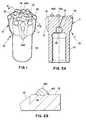
- FIG. 1shows a rock drill bit according to the present invention in a perspective view
- FIG. 2Ashows the drill bit in a cross-section according to line II—II in FIG. 1;
- FIG. 2Bshows a fragment of FIG. 2A depicting the drill bit in an enlarged cross-section
- FIGS. 3A-3Gschematically show a process according to the present invention with spot welding of a button to a drill body
- FIG. 4shows a button according to the present invention in a side view
- FIGS. 5A-5Fschematically show an alternative process according to the present invention involving spot welding of a button to a drill body
- FIGS. 6-10show alternative embodiments of buttons according to the present invention in side views.
- a rock drill bit 10which in a conventional manner comprises a substantially cylindrical head portion 11 and a thinner shank 12 .
- the head portion 11has a working end comprised of a front surface 13 and a peripheral surface 15 .
- a number of front buttons 14 Aare assembled on the front surface 13 .
- the peripheral surface portion 15 between the front surface 13 and the outer periphery of the head portionis conically shaped.
- a number of peripheral buttons 16are arranged on this conical surface portion 15 in the form of a peripheral wreath of buttons 16 .
- the front buttons 14 A and the peripheral or gauge buttons 16may be identical. Parts of the peripheral buttons 16 extend somewhat radially outside the periphery of the head portion such to drill a hole which has a bigger diameter than the head portion. In areas between adjacent peripheral buttons 16 recesses 17 are provided through which flush medium (e.g., water or air) can pass. As is evident from FIG. 2A a main channel 18 for flush medium is provided internally in the drill bit. This main channel transforms at its forward end into a number of branch channels 19 A, 19 , some of which ( 19 A) terminate in said recesses 17 and another of which ( 19 ) terminates in the front surface.
- flush mediume.g., water or air
- At least one of the front buttons 14 Ais provided close to the orifice of the channel and basically axially in front of the branch channel 19 .
- the shape of the button front endmay vary considerably; it can thus be semi-spherical, conical, ballistic or semi-ballistic.
- buttonsare made from wear resistant hard metal, such as wolfram carbide and cobalt pressed together whereafter the formed body is sintered. Since hard metal is an expensive material, the cost of the drill bit would fall significantly if the hard metal portion of a conventional button that normally is pressed downwards into the hole in the steel body could be eliminated. The manufacturing cost should also be lower if hole drilling did not have to be performed to receive such hard metal portions.
- the hard metalis directly secured to the steel body by welding. Welding means that the surfaces are heated and pressed together such that a so-called metallurgical bond with high strength is obtained between the two materials.
- a problem with the welding of hard metalis the high carbon content.
- the carbon content in the steel closest to the jointwill increase at melting, with the risk of brittleness.
- To limit this the welding timeis chosen short, which puts special demands on the choice of welding method.
- FIGS. 3A-3GA suitable welding method where specifically short welding time is characteristic is capacitor discharge spot welding, which is illustrated in FIGS. 3A-3G.
- the methodinvolves connecting the button 14 A and the work piece 13 to a circuit in which a capacitor pack, not shown, is discharged.
- a specially formed tip 22 in the buttonmakes the current very high locally, and an electric arc 43 arises. This electric arc vaporizes the tip and melts the surfaces.
- the buttonis pressed or pushed against the work piece wherein the melt solidifies and a metallurgical or chemical bond arises.
- the course of weldingis very fast, in the magnitude of 1-5 milliseconds (ms), and its progression is shown in FIGS. 3A-3G.
- Weldingcan also be made without a gap, i.e., without step A in the figure, and then the welding time becomes somewhat longer but no longer than 1 second.
- the method steps according to the present invention with reference to FIGS. 3A-3Gconsequently comprise:
- the solidified materialmostly steel, forms an upset 40 around each button.
- the thickness of the weld jointlies within the interval of 1-300 micrometer ( ⁇ m).
- the button 14 Awhose configuration has been adapted to the method according to the present invention, is shown in FIG. 4 .
- the button of hard metalhas a substantially cylindrical shank portion 23 and a semi-spherical working end or end surface 24 .
- the buttonhas a center axis CL.
- the end surfaceis defined by a radius R, the center of which lies in a plane P.
- the shank portion 23has a diameter D.
- the tip 22extends symmetrically about the central axis CL from a lower side 25 A of the button.
- the lower side 25 Ais substantially conical in shape and defines an internal cone angle ⁇ , which is from 150° to less than 180°, i.e., preferably from 150° to about 174°.
- the tiphas a diameter D of about 0.75 mm.
- the shank portion 23has a height h 1 extending from the plane P to a transition 26 between the shank portion 23 and the lower side 25 A, the height h 1 being from 0.2 to 2.8 mm.
- the tip 22 and the lower side 25 Ahave a height h 2 of about 1.2 mm measured from the transition 26 to the bottom of the tip 22 .
- buttons used in percussive rock drilling according to the present inventionhave been listed in the table below. When applicable, the units for the numbers in the table are millimeters.
- the H/D ratiois in the range about 0.4 to 0.7 as is evident from the table, but is definitively smaller than 1.2, i.e. H/D ⁇ 1.2. If the entire length of the button (i.e., H+h 2 ) is compared to the corresponding length of a conventional button it will be seen that the length of the button according to the present invention is about only a third of the length of the conventional button.
- Weldingmay alternatively be made through resistance welding, which is illustrated in FIGS. 5A-5F.
- Heatis generated by means of electric current, which is conducted through two surfaces held together under pressure.
- SCShort Cycle
- ARCARC methods.
- the difference compared to capacitor discharge spot weldingis that a transformer current source is used and the button has a wholly conical lower side instead of a tip. The button is in contact with the work piece from the start but is lifted up a short distance simultaneous as the current is turned on. Thereby an electric arc is formed which melts the surfaces in the manner as described above. Finally the button is pushed downwards into the work piece and the weld is formed.
- the welding timewhich is somewhat longer than for capacitor discharge spot welding, is controlled through regulation of the time between the ignition of the electric arc and when the button is pushed downwards.
- the SC methodis illustrated in FIGS. 5A-5F.
- the SC method steps according to the present invention with reference to FIGS. 5A-5Fconsequently comprise:
- the buttonis initially in contact with the work piece
- buttons 14 A and 14 Bthat have been adapted to the alternative welding method according to the present invention are shown in FIG. 6 .
- the difference between the button 14 B and the above-described button 14 Ais that the button 14 B does not have a tip and therefore the lower side 25 B consists of a wholly conical surface with an inner cone angle about 166°.
- An important common feature for both buttons 14 A and 14 Bis that they have a lower side whose smallest diameter is smaller than the diameter D of the button, i.e. a substantially conical weld joint 41 is obtained. That compensates for a greater degree melting of the steel which normally arises at the mid section of the button.
- the ARC methodis used for bigger dimensions and functions in the same manner as the SC method. Since longer welding times are used, the weld in this case is protected by means of a ceramic ring or gas.
- the welding timedepends on the diameter, for example a time of 200-400 ms for a button with a diameter of 10 mm, but seldom or never exceeds 1 second.
- the hard metalcan be covered with a layer of nickel or cobalt before welding, to increase strength of the joint.
- Hard metal buttons with a diameter of 7 mmwere welded by means of capacitor discharge spot welding to a steel body in a tempered steel of the TYPE SS2244.
- the hard metal buttonswere shaped according to FIG. 4 .
- a lifting height of 1 mmwas used, the voltage was 160 V and the pressure was 50 N for a welding time of 3 ms.
- Hard metal buttons with a diameter of 7 mmwere welded by means of the SC method to a steel body in a tempered steel of the TYPE SS2244.
- the hard metal buttonswere shaped according to FIG. 6 .
- the voltagewas 550 V during the welding time of 20 ms.
- buttonscan be positioned on the front surface of the drill bit to obtain better machining, i.e. a higher penetration rate.
- the buttonscan be secured by welding also on the smooth, conical surface portion 15 .
- the short welding timeenables the welding also of diamond coated buttons.
- Each button 14 A, 14 B according to the present invention, which is to be welded,is shorter in length than a corresponding conventional button, and thus expensive hard metal is saved.
- the button 14 A, 14 Bis not intended to be rotated during welding and therefore could be asymmetrically shaped about its axis and thus needs no driving surfaces.
- the letter “D”represents the biggest width of the asymmetrical button.
- the height hi of the shank of the asymmetric buttonmay be 0 to 15 mm, i.e. its working surface 24 may connect for example directly to the lower side 25 A, 25 B.
- FIG. 7shows a button 14 C according to the present invention, with a ballistic basic form, which is somewhat more aggressive than the above-described buttons.
- FIG. 8shows a button 14 D according to the present invention, with a conical basic form, which is still more aggressive than the above-described buttons.
- FIG. 9shows a button 14 E according to the present invention such as mentioned above, with an asymmetrical, essentially conical basic form.
- the button 14 F according to the present inventionis formed with a shoulder and an intermediate concave portion. The shoulder protects the surrounding steel in the head portion 11 from wear and gives bigger welded surface.
- buttons 14 A- 14 Fmay be formed of material similar to the type of hard metal which is described in U.S. Pat. No. 5,286,549, wherein is shown hard metal bodies, which contain WC and a binder based on at least one of Co, Fe and Ni and which includes a soft core of hard metal surrounded by a harder surface zone of hard metal. It is understood that the buttons 14 C- 14 F can be provided with a tip 22 to enable capacitor discharge spot welding of these buttons.
- the present inventionconsequently brings about a rock drill bit for percussive rock drilling which allows a large degree of freedom regarding the size and location of cavities such as flush channels in the drill body.
- button geometriesare provided and a method that enables a simple and quick mounting of the button to the drill body, which in turn provides material technical advantages.
Landscapes
- Engineering & Computer Science (AREA)
- Geology (AREA)
- Life Sciences & Earth Sciences (AREA)
- Mining & Mineral Resources (AREA)
- Physics & Mathematics (AREA)
- Environmental & Geological Engineering (AREA)
- Fluid Mechanics (AREA)
- Mechanical Engineering (AREA)
- General Life Sciences & Earth Sciences (AREA)
- Geochemistry & Mineralogy (AREA)
- Earth Drilling (AREA)
- Percussive Tools And Related Accessories (AREA)
- Perforating, Stamping-Out Or Severing By Means Other Than Cutting (AREA)
- Forging (AREA)
Abstract
Description
| Diameter D | Prutrusion H | H-h1 | Cyl. Part h1 | H/D |
| 7 | 3.32 | 2.2 | 1.12 | 0.47 |
| 7 | 4.87 | 3.9 | 0.97 | 0.70 |
| 8 | 3.97 | 2.6 | 1.37 | 0.50 |
| 8 | 4.77 | 4.5 | 0.27 | 0.60 |
| 9 | 4.25 | 2.8 | 1.45 | 0.47 |
| 9 | 6.25 | 5 | 1.25 | 0.69 |
| 10 | 4.85 | 3.2 | 1.65 | 0.49 |
| 10 | 6.45 | 5.8 | 0.65 | 0.65 |
| 11 | 4.85 | 3.6 | 1.25 | 0.44 |
| 11 | 7.45 | 6.3 | 1.15 | 0.68 |
| 12 | 5.02 | 3.9 | 1.12 | 0.42 |
| 12 | 7.72 | 7.1 | 0.62 | 0.64 |
| 13 | 5.61 | 4.1 | 1.51 | 0.43 |
| 13 | 8.71 | 7.5 | 1.21 | 0.67 |
| 14 | 6.41 | 4.5 | 1.91 | 0.46 |
| 14 | 9.31 | 8 | 1.31 | 0.67 |
| 16 | 7.86 | 5.1 | 2.76 | 0.49 |
| 16 | 10.66 | 9.3 | 1.36 | 0.67 |
| max | 10.66 | 9.3 | 2.76 | 0.70 |
| min | 3.32 | 2.2 | 0.27 | 0.42 |
Claims (6)
Priority Applications (1)
| Application Number | Priority Date | Filing Date | Title |
|---|---|---|---|
| US10/120,499US6658968B2 (en) | 1999-11-25 | 2002-04-12 | Percussive rock drill bit and buttons therefor and method for manufacturing drill bit |
Applications Claiming Priority (2)
| Application Number | Priority Date | Filing Date | Title |
|---|---|---|---|
| SE9904273ASE515294C2 (en) | 1999-11-25 | 1999-11-25 | Rock drill bit and pins for striking drilling and method of manufacturing a rock drill bit for striking drilling |
| SE9904273 | 1999-11-25 |
Related Child Applications (1)
| Application Number | Title | Priority Date | Filing Date |
|---|---|---|---|
| US10/120,499DivisionUS6658968B2 (en) | 1999-11-25 | 2002-04-12 | Percussive rock drill bit and buttons therefor and method for manufacturing drill bit |
Publications (1)
| Publication Number | Publication Date |
|---|---|
| US6508318B1true US6508318B1 (en) | 2003-01-21 |
Family
ID=20417854
Family Applications (2)
| Application Number | Title | Priority Date | Filing Date |
|---|---|---|---|
| US09/722,006Expired - LifetimeUS6508318B1 (en) | 1999-11-25 | 2000-11-27 | Percussive rock drill bit and buttons therefor and method for manufacturing drill bit |
| US10/120,499Expired - Fee RelatedUS6658968B2 (en) | 1999-11-25 | 2002-04-12 | Percussive rock drill bit and buttons therefor and method for manufacturing drill bit |
Family Applications After (1)
| Application Number | Title | Priority Date | Filing Date |
|---|---|---|---|
| US10/120,499Expired - Fee RelatedUS6658968B2 (en) | 1999-11-25 | 2002-04-12 | Percussive rock drill bit and buttons therefor and method for manufacturing drill bit |
Country Status (11)
| Country | Link |
|---|---|
| US (2) | US6508318B1 (en) |
| EP (1) | EP1232320B1 (en) |
| JP (1) | JP2003515020A (en) |
| AT (1) | ATE288996T1 (en) |
| AU (1) | AU775817B2 (en) |
| BR (1) | BR0015600A (en) |
| CA (1) | CA2391359C (en) |
| DE (1) | DE60018098T2 (en) |
| SE (1) | SE515294C2 (en) |
| WO (1) | WO2001038683A2 (en) |
| ZA (1) | ZA200203542B (en) |
Cited By (25)
| Publication number | Priority date | Publication date | Assignee | Title |
|---|---|---|---|---|
| US20040182610A1 (en)* | 2001-08-01 | 2004-09-23 | Josef Mocivnik | Drill crown |
| US20080035380A1 (en)* | 2006-08-11 | 2008-02-14 | Hall David R | Pointed Diamond Working Ends on a Shear Bit |
| US20080035387A1 (en)* | 2006-08-11 | 2008-02-14 | Hall David R | Downhole Drill Bit |
| US7347292B1 (en) | 2006-10-26 | 2008-03-25 | Hall David R | Braze material for an attack tool |
| US20080099250A1 (en)* | 2006-10-26 | 2008-05-01 | Hall David R | Superhard Insert with an Interface |
| US20090051211A1 (en)* | 2006-10-26 | 2009-02-26 | Hall David R | Thick Pointed Superhard Material |
| US20090133938A1 (en)* | 2006-08-11 | 2009-05-28 | Hall David R | Thermally Stable Pointed Diamond with Increased Impact Resistance |
| US20090184564A1 (en)* | 2008-01-22 | 2009-07-23 | The William J. Brady Loving Trust | Pcd percussion drill bit |
| US20100018776A1 (en)* | 2008-07-28 | 2010-01-28 | Keller Donald E | Cutting bit for mining and excavating tools |
| US20100025114A1 (en)* | 2008-01-22 | 2010-02-04 | Brady William J | PCD Percussion Drill Bit |
| US20100065332A1 (en)* | 2006-08-11 | 2010-03-18 | Hall David R | Method for Drilling with a Fixed Bladed Bit |
| US20100206641A1 (en)* | 2009-02-17 | 2010-08-19 | Hall David R | Chamfered Pointed Enhanced Diamond Insert |
| US20100263939A1 (en)* | 2006-10-26 | 2010-10-21 | Hall David R | High Impact Resistant Tool with an Apex Width between a First and Second Transitions |
| US20130026811A1 (en)* | 2011-07-28 | 2013-01-31 | Boundary Equipment Co. Ltd. | Tool insert |
| US8434573B2 (en) | 2006-08-11 | 2013-05-07 | Schlumberger Technology Corporation | Degradation assembly |
| US20130171583A1 (en)* | 2010-06-30 | 2013-07-04 | Mutsunori SHIOIRI | Medical cutting instrument |
| US8540037B2 (en) | 2008-04-30 | 2013-09-24 | Schlumberger Technology Corporation | Layered polycrystalline diamond |
| US8567532B2 (en) | 2006-08-11 | 2013-10-29 | Schlumberger Technology Corporation | Cutting element attached to downhole fixed bladed bit at a positive rake angle |
| US8701799B2 (en) | 2009-04-29 | 2014-04-22 | Schlumberger Technology Corporation | Drill bit cutter pocket restitution |
| JP2014214426A (en)* | 2013-04-22 | 2014-11-17 | 三菱マテリアル株式会社 | Excavation chip and excavation tool using the same |
| US9051794B2 (en) | 2007-04-12 | 2015-06-09 | Schlumberger Technology Corporation | High impact shearing element |
| US9051795B2 (en) | 2006-08-11 | 2015-06-09 | Schlumberger Technology Corporation | Downhole drill bit |
| US9068410B2 (en) | 2006-10-26 | 2015-06-30 | Schlumberger Technology Corporation | Dense diamond body |
| US9366089B2 (en) | 2006-08-11 | 2016-06-14 | Schlumberger Technology Corporation | Cutting element attached to downhole fixed bladed bit at a positive rake angle |
| US9915102B2 (en) | 2006-08-11 | 2018-03-13 | Schlumberger Technology Corporation | Pointed working ends on a bit |
Families Citing this family (46)
| Publication number | Priority date | Publication date | Assignee | Title |
|---|---|---|---|---|
| SE516432C2 (en)* | 2000-05-03 | 2002-01-15 | Sandvik Ab | Rolling drill bit for rotary crushing rock drilling and method for manufacturing the roller drill bit and crushing means for rotating, crushing drilling |
| USD496948S1 (en) | 2003-06-12 | 2004-10-05 | Luc Charland | Square drill bit |
| US7959094B2 (en)* | 2004-08-20 | 2011-06-14 | Tetra Corporation | Virtual electrode mineral particle disintegrator |
| US8172006B2 (en) | 2004-08-20 | 2012-05-08 | Sdg, Llc | Pulsed electric rock drilling apparatus with non-rotating bit |
| US7416032B2 (en)* | 2004-08-20 | 2008-08-26 | Tetra Corporation | Pulsed electric rock drilling apparatus |
| US9190190B1 (en) | 2004-08-20 | 2015-11-17 | Sdg, Llc | Method of providing a high permittivity fluid |
| US8186454B2 (en)* | 2004-08-20 | 2012-05-29 | Sdg, Llc | Apparatus and method for electrocrushing rock |
| US9016359B2 (en) | 2004-08-20 | 2015-04-28 | Sdg, Llc | Apparatus and method for supplying electrical power to an electrocrushing drill |
| US8789772B2 (en) | 2004-08-20 | 2014-07-29 | Sdg, Llc | Virtual electrode mineral particle disintegrator |
| US8499860B2 (en)* | 2005-12-14 | 2013-08-06 | Smith International, Inc. | Cutting elements having cutting edges with continuous varying radii and bits incorporating the same |
| US10060195B2 (en) | 2006-06-29 | 2018-08-28 | Sdg Llc | Repetitive pulsed electric discharge apparatuses and methods of use |
| US20080156539A1 (en)* | 2006-12-28 | 2008-07-03 | Ziegenfuss Mark R | Non-rotating drill system and method |
| USD574403S1 (en)* | 2007-03-09 | 2008-08-05 | The William J. Brady Loving Trust | Hard rock percussion drill bit with paraboloid PCD inserts |
| CA126500S (en)* | 2008-02-26 | 2009-03-20 | Sandvik Intellectual Property | Rock drill bit |
| CA126499S (en)* | 2008-02-26 | 2009-03-20 | Sandvik Intellectual Property | Drill bit |
| EP2369127A1 (en)* | 2010-03-09 | 2011-09-28 | Sandvik Intellectual Property AB | A rock drill bit, a drilling assembly and a method for percussive rock drilling |
| DE102011007694A1 (en)* | 2011-04-19 | 2012-10-25 | Robert Bosch Gmbh | Drilling tool or method for producing a drilling tool |
| US10407995B2 (en) | 2012-07-05 | 2019-09-10 | Sdg Llc | Repetitive pulsed electric discharge drills including downhole formation evaluation |
| USD705827S1 (en)* | 2012-09-07 | 2014-05-27 | Sandvik Intellectual Property Ab | Drill bit for percussive drilling |
| JP2014196615A (en)* | 2013-03-29 | 2014-10-16 | 三菱マテリアル株式会社 | Drilling bit and drilling tip used therefor |
| JP2014196616A (en)* | 2013-03-29 | 2014-10-16 | 三菱マテリアル株式会社 | Drilling bit |
| USD725164S1 (en)* | 2013-07-25 | 2015-03-24 | Padley & Venables Limited | Percussive drill bit |
| WO2015042608A1 (en) | 2013-09-23 | 2015-03-26 | Sdg Llc | Method and apparatus for isolating and switching lower voltage pulses from high voltage pulses in electrocrushing and electrohydraulic drills |
| PL2865843T3 (en) | 2013-10-28 | 2016-07-29 | Sandvik Intellectual Property | Percussive rock drill bit with optimised gauge buttons |
| PL2902583T3 (en) | 2014-01-31 | 2017-09-29 | Sandvik Intellectual Property Ab | Percussive rock drill bit with flushing grooves |
| US10487588B2 (en) | 2014-05-15 | 2019-11-26 | Dover Bmcs Acquisition Corp. | Percussion drill bit with at least one wear insert, related systems, and methods |
| EP2990589B1 (en) | 2014-08-25 | 2017-05-03 | Sandvik Intellectual Property AB | Drill bit with recessed cutting face |
| USD872142S1 (en)* | 2015-05-21 | 2020-01-07 | Center Rock Inc. | Drill bit for a down-the-hole drill hammer |
| CA165392S (en)* | 2015-05-29 | 2016-06-16 | Atlas Copco Secoroc Ab | Rock drill bit |
| JP1569597S (en)* | 2016-07-14 | 2017-02-20 | ||
| JP1569589S (en)* | 2016-07-14 | 2017-02-20 | ||
| JP1569599S (en)* | 2016-07-14 | 2017-02-20 | ||
| GB2557190B (en)* | 2016-11-29 | 2020-09-16 | Mincon Int Ltd | Drill bits |
| USD882788S1 (en)* | 2018-01-31 | 2020-04-28 | Beijing Smtp Technology Co., Ltd. | Ultrasonic cutter head |
| USD882084S1 (en)* | 2018-01-31 | 2020-04-21 | Beijing Smtp Technology Co., Ltd. | Ultrasonic cutter head |
| USD861051S1 (en)* | 2018-03-13 | 2019-09-24 | Robit Oyj | Drill bit |
| USD870168S1 (en) | 2018-03-13 | 2019-12-17 | Robit Oyj | Drill bit |
| EP3617438A1 (en) | 2018-08-30 | 2020-03-04 | Sandvik Mining and Construction Tools AB | Percussive drill bit with radially extended front face |
| JP7294030B2 (en)* | 2018-09-28 | 2023-06-20 | 三菱マテリアル株式会社 | drilling tips and drilling bits |
| US11821264B2 (en) | 2018-09-28 | 2023-11-21 | Mitsubishi Materials Corporation | Drilling tip and drill bit |
| USD1009108S1 (en)* | 2020-09-21 | 2023-12-26 | Kyocera Unimerco Tooling A/S | Drill |
| USD1044894S1 (en)* | 2022-07-09 | 2024-10-01 | Zhejiang Pulanka Rock Tools Co., Ltd. | Button drill bit |
| USD1046584S1 (en)* | 2022-09-16 | 2024-10-15 | Boart Longyear Company | Drill bit |
| USD1068887S1 (en)* | 2023-01-12 | 2025-04-01 | Boart Longyear Manufacturing And Distribution Inc. | Drill bit |
| EP4528068A1 (en)* | 2023-09-25 | 2025-03-26 | Sandvik Mining and Construction Tools AB | Mining tool with asymmetric cutting insert |
| CN116988739B (en)* | 2023-09-26 | 2023-12-26 | 西南石油大学 | A high-density longitudinally arranged PDC drill bit |
Citations (14)
| Publication number | Priority date | Publication date | Assignee | Title |
|---|---|---|---|---|
| US4014395A (en)* | 1974-12-05 | 1977-03-29 | Smith-Williston, Inc. | Rock drill bit insert retaining sleeve assembly |
| US4296825A (en)* | 1977-11-25 | 1981-10-27 | Sandvik Aktiebolag | Rock drill |
| US4595067A (en)* | 1984-01-17 | 1986-06-17 | Reed Tool Company | Rotary drill bit, parts therefor, and method of manufacturing thereof |
| US4854405A (en)* | 1988-01-04 | 1989-08-08 | American National Carbide Company | Cutting tools |
| US5286549A (en) | 1991-02-18 | 1994-02-15 | Sandvik Ab | Cemented carbide body used preferably for abrasive rock drilling and mineral cutting |
| US5379854A (en)* | 1993-08-17 | 1995-01-10 | Dennis Tool Company | Cutting element for drill bits |
| US5647449A (en)* | 1996-01-26 | 1997-07-15 | Dennis; Mahlon | Crowned surface with PDC layer |
| US5845547A (en)* | 1996-09-09 | 1998-12-08 | The Sollami Company | Tool having a tungsten carbide insert |
| US5848657A (en)* | 1996-12-27 | 1998-12-15 | General Electric Company | Polycrystalline diamond cutting element |
| US5890551A (en)* | 1996-03-14 | 1999-04-06 | Sandvik Ab | Rock drilling tool including a drill bit having a recess in a front surface thereof |
| GB2348899A (en) | 1999-04-16 | 2000-10-18 | Baker Hughes Inc | Earth boring : drill bit : insert |
| US6196340B1 (en)* | 1997-11-28 | 2001-03-06 | U.S. Synthetic Corporation | Surface geometry for non-planar drill inserts |
| US6202768B1 (en)* | 1998-03-23 | 2001-03-20 | Sandvik Ab | Rock drilling tool and reamer for percussive drilling |
| US6220376B1 (en)* | 1998-11-20 | 2001-04-24 | Sandvik Ab | Drill bit and button |
Family Cites Families (9)
| Publication number | Priority date | Publication date | Assignee | Title |
|---|---|---|---|---|
| CA1216158A (en)* | 1981-11-09 | 1987-01-06 | Akio Hara | Composite compact component and a process for the production of the same |
| US4765205A (en)* | 1987-06-01 | 1988-08-23 | Bob Higdon | Method of assembling drill bits and product assembled thereby |
| US5131481A (en)* | 1990-12-19 | 1992-07-21 | Kennametal Inc. | Insert having a surface of carbide particles |
| JP2544895Y2 (en)* | 1991-06-10 | 1997-08-20 | 東芝タンガロイ株式会社 | Bit chip for drilling and drill bit incorporating this |
| JPH0557085U (en)* | 1992-01-07 | 1993-07-30 | 東邦金属株式会社 | Cutter bit mounting structure |
| USH1566H (en)* | 1993-11-09 | 1996-08-06 | Smith International, Inc. | Matrix diamond drag bit with PCD cylindrical cutters |
| JPH10252372A (en)* | 1997-03-11 | 1998-09-22 | Tone Chika Gijutsu Kk | Excavation bit and excavation casing using the same |
| US6135218A (en)* | 1999-03-09 | 2000-10-24 | Camco International Inc. | Fixed cutter drill bits with thin, integrally formed wear and erosion resistant surfaces |
| GB9906114D0 (en)* | 1999-03-18 | 1999-05-12 | Camco Int Uk Ltd | A method of applying a wear-resistant layer to a surface of a downhole component |
- 1999
- 1999-11-25SESE9904273Apatent/SE515294C2/enunknown
- 2000
- 2000-11-17WOPCT/SE2000/002255patent/WO2001038683A2/enactiveIP Right Grant
- 2000-11-17CACA002391359Apatent/CA2391359C/ennot_activeExpired - Fee Related
- 2000-11-17JPJP2001540009Apatent/JP2003515020A/enactivePending
- 2000-11-17ATAT00978174Tpatent/ATE288996T1/enactive
- 2000-11-17EPEP00978174Apatent/EP1232320B1/ennot_activeExpired - Lifetime
- 2000-11-17DEDE60018098Tpatent/DE60018098T2/ennot_activeExpired - Lifetime
- 2000-11-17BRBR0015600-0Apatent/BR0015600A/ennot_activeIP Right Cessation
- 2000-11-17AUAU15659/01Apatent/AU775817B2/ennot_activeCeased
- 2000-11-27USUS09/722,006patent/US6508318B1/ennot_activeExpired - Lifetime
- 2002
- 2002-04-12USUS10/120,499patent/US6658968B2/ennot_activeExpired - Fee Related
- 2002-05-03ZAZA200203542Apatent/ZA200203542B/enunknown
Patent Citations (14)
| Publication number | Priority date | Publication date | Assignee | Title |
|---|---|---|---|---|
| US4014395A (en)* | 1974-12-05 | 1977-03-29 | Smith-Williston, Inc. | Rock drill bit insert retaining sleeve assembly |
| US4296825A (en)* | 1977-11-25 | 1981-10-27 | Sandvik Aktiebolag | Rock drill |
| US4595067A (en)* | 1984-01-17 | 1986-06-17 | Reed Tool Company | Rotary drill bit, parts therefor, and method of manufacturing thereof |
| US4854405A (en)* | 1988-01-04 | 1989-08-08 | American National Carbide Company | Cutting tools |
| US5286549A (en) | 1991-02-18 | 1994-02-15 | Sandvik Ab | Cemented carbide body used preferably for abrasive rock drilling and mineral cutting |
| US5379854A (en)* | 1993-08-17 | 1995-01-10 | Dennis Tool Company | Cutting element for drill bits |
| US5647449A (en)* | 1996-01-26 | 1997-07-15 | Dennis; Mahlon | Crowned surface with PDC layer |
| US5890551A (en)* | 1996-03-14 | 1999-04-06 | Sandvik Ab | Rock drilling tool including a drill bit having a recess in a front surface thereof |
| US5845547A (en)* | 1996-09-09 | 1998-12-08 | The Sollami Company | Tool having a tungsten carbide insert |
| US5848657A (en)* | 1996-12-27 | 1998-12-15 | General Electric Company | Polycrystalline diamond cutting element |
| US6196340B1 (en)* | 1997-11-28 | 2001-03-06 | U.S. Synthetic Corporation | Surface geometry for non-planar drill inserts |
| US6202768B1 (en)* | 1998-03-23 | 2001-03-20 | Sandvik Ab | Rock drilling tool and reamer for percussive drilling |
| US6220376B1 (en)* | 1998-11-20 | 2001-04-24 | Sandvik Ab | Drill bit and button |
| GB2348899A (en) | 1999-04-16 | 2000-10-18 | Baker Hughes Inc | Earth boring : drill bit : insert |
Cited By (46)
| Publication number | Priority date | Publication date | Assignee | Title |
|---|---|---|---|---|
| US20040182610A1 (en)* | 2001-08-01 | 2004-09-23 | Josef Mocivnik | Drill crown |
| US6926104B2 (en)* | 2001-08-01 | 2005-08-09 | Techmo Entwicklungs- Und Vertriebs Gmbh | Drill crown |
| US8590644B2 (en) | 2006-08-11 | 2013-11-26 | Schlumberger Technology Corporation | Downhole drill bit |
| US8567532B2 (en) | 2006-08-11 | 2013-10-29 | Schlumberger Technology Corporation | Cutting element attached to downhole fixed bladed bit at a positive rake angle |
| US20080035380A1 (en)* | 2006-08-11 | 2008-02-14 | Hall David R | Pointed Diamond Working Ends on a Shear Bit |
| US9051795B2 (en) | 2006-08-11 | 2015-06-09 | Schlumberger Technology Corporation | Downhole drill bit |
| US8714285B2 (en) | 2006-08-11 | 2014-05-06 | Schlumberger Technology Corporation | Method for drilling with a fixed bladed bit |
| US8622155B2 (en) | 2006-08-11 | 2014-01-07 | Schlumberger Technology Corporation | Pointed diamond working ends on a shear bit |
| US9915102B2 (en) | 2006-08-11 | 2018-03-13 | Schlumberger Technology Corporation | Pointed working ends on a bit |
| US20080035387A1 (en)* | 2006-08-11 | 2008-02-14 | Hall David R | Downhole Drill Bit |
| US20090133938A1 (en)* | 2006-08-11 | 2009-05-28 | Hall David R | Thermally Stable Pointed Diamond with Increased Impact Resistance |
| US9366089B2 (en) | 2006-08-11 | 2016-06-14 | Schlumberger Technology Corporation | Cutting element attached to downhole fixed bladed bit at a positive rake angle |
| US10378288B2 (en) | 2006-08-11 | 2019-08-13 | Schlumberger Technology Corporation | Downhole drill bit incorporating cutting elements of different geometries |
| US8434573B2 (en) | 2006-08-11 | 2013-05-07 | Schlumberger Technology Corporation | Degradation assembly |
| US9708856B2 (en) | 2006-08-11 | 2017-07-18 | Smith International, Inc. | Downhole drill bit |
| US20100065332A1 (en)* | 2006-08-11 | 2010-03-18 | Hall David R | Method for Drilling with a Fixed Bladed Bit |
| US8215420B2 (en) | 2006-08-11 | 2012-07-10 | Schlumberger Technology Corporation | Thermally stable pointed diamond with increased impact resistance |
| US7469756B2 (en) | 2006-10-26 | 2008-12-30 | Hall David R | Tool with a large volume of a superhard material |
| US9068410B2 (en) | 2006-10-26 | 2015-06-30 | Schlumberger Technology Corporation | Dense diamond body |
| US20100263939A1 (en)* | 2006-10-26 | 2010-10-21 | Hall David R | High Impact Resistant Tool with an Apex Width between a First and Second Transitions |
| US8109349B2 (en) | 2006-10-26 | 2012-02-07 | Schlumberger Technology Corporation | Thick pointed superhard material |
| US10029391B2 (en) | 2006-10-26 | 2018-07-24 | Schlumberger Technology Corporation | High impact resistant tool with an apex width between a first and second transitions |
| US7665552B2 (en) | 2006-10-26 | 2010-02-23 | Hall David R | Superhard insert with an interface |
| US8960337B2 (en) | 2006-10-26 | 2015-02-24 | Schlumberger Technology Corporation | High impact resistant tool with an apex width between a first and second transitions |
| US7347292B1 (en) | 2006-10-26 | 2008-03-25 | Hall David R | Braze material for an attack tool |
| US9540886B2 (en) | 2006-10-26 | 2017-01-10 | Schlumberger Technology Corporation | Thick pointed superhard material |
| US7353893B1 (en) | 2006-10-26 | 2008-04-08 | Hall David R | Tool with a large volume of a superhard material |
| US20090051211A1 (en)* | 2006-10-26 | 2009-02-26 | Hall David R | Thick Pointed Superhard Material |
| US20080099249A1 (en)* | 2006-10-26 | 2008-05-01 | Hall David R | Tool with a large volume of a superhard material |
| US20080099250A1 (en)* | 2006-10-26 | 2008-05-01 | Hall David R | Superhard Insert with an Interface |
| US8028774B2 (en) | 2006-10-26 | 2011-10-04 | Schlumberger Technology Corporation | Thick pointed superhard material |
| US8365845B2 (en) | 2007-02-12 | 2013-02-05 | Hall David R | High impact resistant tool |
| US9051794B2 (en) | 2007-04-12 | 2015-06-09 | Schlumberger Technology Corporation | High impact shearing element |
| US20090184564A1 (en)* | 2008-01-22 | 2009-07-23 | The William J. Brady Loving Trust | Pcd percussion drill bit |
| US20100025114A1 (en)* | 2008-01-22 | 2010-02-04 | Brady William J | PCD Percussion Drill Bit |
| US8931854B2 (en) | 2008-04-30 | 2015-01-13 | Schlumberger Technology Corporation | Layered polycrystalline diamond |
| US8540037B2 (en) | 2008-04-30 | 2013-09-24 | Schlumberger Technology Corporation | Layered polycrystalline diamond |
| US20100018776A1 (en)* | 2008-07-28 | 2010-01-28 | Keller Donald E | Cutting bit for mining and excavating tools |
| US8061457B2 (en) | 2009-02-17 | 2011-11-22 | Schlumberger Technology Corporation | Chamfered pointed enhanced diamond insert |
| US20100206641A1 (en)* | 2009-02-17 | 2010-08-19 | Hall David R | Chamfered Pointed Enhanced Diamond Insert |
| US8701799B2 (en) | 2009-04-29 | 2014-04-22 | Schlumberger Technology Corporation | Drill bit cutter pocket restitution |
| US20130171583A1 (en)* | 2010-06-30 | 2013-07-04 | Mutsunori SHIOIRI | Medical cutting instrument |
| US10350715B2 (en)* | 2010-06-30 | 2019-07-16 | Mani , Inc. | Method of producing a medical cutting instrument |
| US9120243B2 (en)* | 2011-07-28 | 2015-09-01 | Boundary Equipment Co. Ltd. | Tool insert |
| US20130026811A1 (en)* | 2011-07-28 | 2013-01-31 | Boundary Equipment Co. Ltd. | Tool insert |
| JP2014214426A (en)* | 2013-04-22 | 2014-11-17 | 三菱マテリアル株式会社 | Excavation chip and excavation tool using the same |
Also Published As
| Publication number | Publication date |
|---|---|
| EP1232320B1 (en) | 2005-02-09 |
| CA2391359C (en) | 2007-10-09 |
| SE9904273D0 (en) | 1999-11-25 |
| WO2001038683A3 (en) | 2001-12-20 |
| SE9904273L (en) | 2001-05-26 |
| WO2001038683A8 (en) | 2001-09-27 |
| JP2003515020A (en) | 2003-04-22 |
| BR0015600A (en) | 2002-07-09 |
| SE515294C2 (en) | 2001-07-09 |
| DE60018098T2 (en) | 2006-01-19 |
| AU775817B2 (en) | 2004-08-19 |
| EP1232320A2 (en) | 2002-08-21 |
| ZA200203542B (en) | 2003-08-04 |
| US6658968B2 (en) | 2003-12-09 |
| ATE288996T1 (en) | 2005-02-15 |
| AU1565901A (en) | 2001-06-04 |
| US20020153174A1 (en) | 2002-10-24 |
| DE60018098D1 (en) | 2005-03-17 |
| CA2391359A1 (en) | 2001-05-31 |
| WO2001038683A2 (en) | 2001-05-31 |
Similar Documents
| Publication | Publication Date | Title |
|---|---|---|
| US6508318B1 (en) | Percussive rock drill bit and buttons therefor and method for manufacturing drill bit | |
| US4686080A (en) | Composite compact having a base of a hard-centered alloy in which the base is joined to a substrate through a joint layer and process for producing the same | |
| CN100358670C (en) | Fusion structure and method for hard alloy and diamond piece, drilling tool and cutting piece thereof | |
| CA1286510C (en) | Stick of composite materials and process for preparation thereof | |
| US7611210B2 (en) | Cutting bit body and method for making the same | |
| CA1101246A (en) | Method for making rock bits | |
| US20090051212A1 (en) | Reduced volume cutting tip and cutter bit assembly incorporating same | |
| CN214741117U (en) | Polycrystalline diamond compact, PDC bearing assembly and cutting tool | |
| US20020000336A1 (en) | Method for the manufacturing of a cone cutter for rotary drilling by crushing, a rotary cone drill bit, a cone cutter and crushing elements therefor | |
| US20140291033A1 (en) | Methodologies for manufacturing short matrix bits | |
| CN214886868U (en) | Composite tooth | |
| CA2302492A1 (en) | Rock drill and method for manufacturing said rock drill | |
| JP2008144541A (en) | Drilling bit | |
| CN218744950U (en) | Radial drilling machine drilling tool | |
| KR20200049211A (en) | Manufacturing method of polycrystalline diamond tool | |
| US20200300086A1 (en) | Bit | |
| CN113216860A (en) | Composite tooth and method for manufacturing same | |
| GB2639119A (en) | Insert | |
| JPH08168905A (en) | Cutting tool | |
| JPS5884188A (en) | Composite sintered body tool and manufacture | |
| JPH0825141A (en) | Drilling tool | |
| JP2003326411A (en) | Drill for shape steel | |
| CA2638857A1 (en) | Reduced volume cutting tip and cutter bit assembly incorporating same |
Legal Events
| Date | Code | Title | Description |
|---|---|---|---|
| AS | Assignment | Owner name:SANDVIK AB, SWEDEN Free format text:ASSIGNMENT OF ASSIGNORS INTEREST;ASSIGNORS:LINDEN, JOHAN;LUNDELL, LARS-GUNNAR;REEL/FRAME:011733/0907 Effective date:20010129 | |
| STCF | Information on status: patent grant | Free format text:PATENTED CASE | |
| AS | Assignment | Owner name:SANDVIK INTELLECTUAL PROPERTY HB, SWEDEN Free format text:ASSIGNMENT OF ASSIGNORS INTEREST;ASSIGNOR:SANDVIK AB;REEL/FRAME:016290/0628 Effective date:20050516 Owner name:SANDVIK INTELLECTUAL PROPERTY HB,SWEDEN Free format text:ASSIGNMENT OF ASSIGNORS INTEREST;ASSIGNOR:SANDVIK AB;REEL/FRAME:016290/0628 Effective date:20050516 | |
| AS | Assignment | Owner name:SANDVIK INTELLECTUAL PROPERTY AKTIEBOLAG, SWEDEN Free format text:ASSIGNMENT OF ASSIGNORS INTEREST;ASSIGNOR:SANDVIK INTELLECTUAL PROPERTY HB;REEL/FRAME:016621/0366 Effective date:20050630 Owner name:SANDVIK INTELLECTUAL PROPERTY AKTIEBOLAG,SWEDEN Free format text:ASSIGNMENT OF ASSIGNORS INTEREST;ASSIGNOR:SANDVIK INTELLECTUAL PROPERTY HB;REEL/FRAME:016621/0366 Effective date:20050630 | |
| FPAY | Fee payment | Year of fee payment:4 | |
| FPAY | Fee payment | Year of fee payment:8 | |
| FPAY | Fee payment | Year of fee payment:12 |