US6507419B1 - Illumination system using optical feedback - Google Patents
Illumination system using optical feedbackDownload PDFInfo
- Publication number
- US6507419B1 US6507419B1US09/533,608US53360800AUS6507419B1US 6507419 B1US6507419 B1US 6507419B1US 53360800 AUS53360800 AUS 53360800AUS 6507419 B1US6507419 B1US 6507419B1
- Authority
- US
- United States
- Prior art keywords
- light
- bandwidth
- holographic optical
- optical element
- control signals
- Prior art date
- Legal status (The legal status is an assumption and is not a legal conclusion. Google has not performed a legal analysis and makes no representation as to the accuracy of the status listed.)
- Expired - Fee Related
Links
- 230000003287optical effectEffects0.000titleclaimsabstractdescription208
- 238000005286illuminationMethods0.000titleabstractdescription42
- 230000004044responseEffects0.000claimsdescription26
- 230000004075alterationEffects0.000claimsdescription22
- 239000000463materialSubstances0.000claimsdescription11
- 239000004973liquid crystal related substanceSubstances0.000claimsdescription9
- 239000004983Polymer Dispersed Liquid CrystalSubstances0.000claimsdescription8
- 239000000178monomerSubstances0.000claims4
- 238000004132cross linkingMethods0.000claims2
- 230000010287polarizationEffects0.000claims2
- 238000001914filtrationMethods0.000abstractdescription13
- 238000004891communicationMethods0.000abstractdescription2
- 239000000654additiveSubstances0.000description13
- 230000000996additive effectEffects0.000description13
- 235000013619trace mineralNutrition0.000description8
- 239000011573trace mineralSubstances0.000description8
- 230000003247decreasing effectEffects0.000description6
- 238000010586diagramMethods0.000description5
- 230000006870functionEffects0.000description5
- 239000011521glassSubstances0.000description4
- 230000003068static effectEffects0.000description3
- 230000008859changeEffects0.000description2
- 238000000576coating methodMethods0.000description2
- 230000005684electric fieldEffects0.000description2
- 238000000034methodMethods0.000description2
- 238000012986modificationMethods0.000description2
- 230000004048modificationEffects0.000description2
- 235000012771pancakesNutrition0.000description2
- 230000008569processEffects0.000description2
- 230000003595spectral effectEffects0.000description2
- 239000000758substrateSubstances0.000description2
- 230000032683agingEffects0.000description1
- 239000003990capacitorSubstances0.000description1
- 239000011248coating agentSubstances0.000description1
- 238000007796conventional methodMethods0.000description1
- 239000012769display materialSubstances0.000description1
- 230000008030eliminationEffects0.000description1
- 238000003379elimination reactionMethods0.000description1
- AMGQUBHHOARCQH-UHFFFAOYSA-Nindium;oxotinChemical compound[In].[Sn]=OAMGQUBHHOARCQH-UHFFFAOYSA-N0.000description1
- 230000003993interactionEffects0.000description1
- 239000000203mixtureSubstances0.000description1
- 230000007935neutral effectEffects0.000description1
- 238000005191phase separationMethods0.000description1
- 230000009467reductionEffects0.000description1
- 239000007787solidSubstances0.000description1
- 238000012546transferMethods0.000description1
Images


Classifications
- G—PHYSICS
- G02—OPTICS
- G02B—OPTICAL ELEMENTS, SYSTEMS OR APPARATUS
- G02B5/00—Optical elements other than lenses
- G02B5/32—Holograms used as optical elements
- G—PHYSICS
- G02—OPTICS
- G02B—OPTICAL ELEMENTS, SYSTEMS OR APPARATUS
- G02B5/00—Optical elements other than lenses
- G02B5/20—Filters
- G02B5/203—Filters having holographic or diffractive elements
- G—PHYSICS
- G02—OPTICS
- G02F—OPTICAL DEVICES OR ARRANGEMENTS FOR THE CONTROL OF LIGHT BY MODIFICATION OF THE OPTICAL PROPERTIES OF THE MEDIA OF THE ELEMENTS INVOLVED THEREIN; NON-LINEAR OPTICS; FREQUENCY-CHANGING OF LIGHT; OPTICAL LOGIC ELEMENTS; OPTICAL ANALOGUE/DIGITAL CONVERTERS
- G02F1/00—Devices or arrangements for the control of the intensity, colour, phase, polarisation or direction of light arriving from an independent light source, e.g. switching, gating or modulating; Non-linear optics
- G02F1/01—Devices or arrangements for the control of the intensity, colour, phase, polarisation or direction of light arriving from an independent light source, e.g. switching, gating or modulating; Non-linear optics for the control of the intensity, phase, polarisation or colour
- G02F1/13—Devices or arrangements for the control of the intensity, colour, phase, polarisation or direction of light arriving from an independent light source, e.g. switching, gating or modulating; Non-linear optics for the control of the intensity, phase, polarisation or colour based on liquid crystals, e.g. single liquid crystal display cells
- G02F1/133—Constructional arrangements; Operation of liquid crystal cells; Circuit arrangements
- G02F1/13306—Circuit arrangements or driving methods for the control of single liquid crystal cells
- G02F1/13318—Circuits comprising a photodetector
- G—PHYSICS
- G02—OPTICS
- G02F—OPTICAL DEVICES OR ARRANGEMENTS FOR THE CONTROL OF LIGHT BY MODIFICATION OF THE OPTICAL PROPERTIES OF THE MEDIA OF THE ELEMENTS INVOLVED THEREIN; NON-LINEAR OPTICS; FREQUENCY-CHANGING OF LIGHT; OPTICAL LOGIC ELEMENTS; OPTICAL ANALOGUE/DIGITAL CONVERTERS
- G02F1/00—Devices or arrangements for the control of the intensity, colour, phase, polarisation or direction of light arriving from an independent light source, e.g. switching, gating or modulating; Non-linear optics
- G02F1/01—Devices or arrangements for the control of the intensity, colour, phase, polarisation or direction of light arriving from an independent light source, e.g. switching, gating or modulating; Non-linear optics for the control of the intensity, phase, polarisation or colour
- G02F1/13—Devices or arrangements for the control of the intensity, colour, phase, polarisation or direction of light arriving from an independent light source, e.g. switching, gating or modulating; Non-linear optics for the control of the intensity, phase, polarisation or colour based on liquid crystals, e.g. single liquid crystal display cells
- G02F1/133—Constructional arrangements; Operation of liquid crystal cells; Circuit arrangements
- G02F1/1333—Constructional arrangements; Manufacturing methods
- G02F1/1334—Constructional arrangements; Manufacturing methods based on polymer dispersed liquid crystals, e.g. microencapsulated liquid crystals
- G02F1/13342—Holographic polymer dispersed liquid crystals
Definitions
- the present inventionrelates generally to illumination systems, and more particularly to an illumination system using optical feedback.
- Illumination systemsgenerate light for illuminating objects including image displays.
- the output light of conventional illumination systemsoften varies in intensity.
- the variance in intensitymay be uniform across the spectral frequency of the output light or localized in a non-uniform fashion to one or more visible bandwidths (e.g. red, green, or blue light) thereof.
- the inconsistenciesmay result from a variety of factors including temperature variations of the light source of the illumination system, age related physical changes in the light source, or changes in the ambient conditions in which the light source operates.
- the present inventionrelates to an illumination system using optical feedback to maintain a predetermined light intensity output.
- the illumination systememploys an electrically controllable optical filter for filtering light received thereby.
- the illumination systemalso includes a light detector for detecting at least a portion of the light filtered by the electrically controllable optical filter.
- the light detectoris in data communication with the electrically controllable optical filter. Some or all light filtered by the electrically controllable optical filter is detected by the light detector, which, in turn generates a corresponding signal that is compared to at least one predetermined value.
- one or more filtering characteristics of the electrically controllable optical filterare varied which, in turn, varies the amount of light filtered by the electrically controllable optical filter.
- the filtering characteristics of the electrically controllable optical filtercontinue to be varied until the signal generated by the light detector substantially matches the at least one predetermined value.
- the electrically controllable optical filterincludes one or more electrically switchable holographic optical elements.
- Each of the electrically switchable holographic optical elementsoperates between an active state and an inactive state depending upon the magnitude of a voltage received thereby.
- the inactive statelight incident upon the electrically switchable holographic optical element is transmitted therethrough without substantial alteration.
- the electrically switchable holographic optical elementdiffracts a select bandwidth of the received incident light into at least a zero order-diffracted component and a first order diffracted component. The remaining, undiffracted portions of incident light are transmitted by the activated electrically switchable holographic optical element without substantial alteration.
- the intensity of light in the zero order-diffracted component and the first order diffracted componentdepends on the magnitude of the voltage received by the electrically switchable holographic optical element.
- FIG. 1is a block diagram of an illumination system according to one embodiment of the present invention.
- FIG. 2is a block diagram of an illumination system according to another embodiment of the present invention.
- FIG. 3is a block diagram of a feedback system that may be used to control the electrically controllable optical filter shown in FIGS. 1 and 2;
- FIG. 4is a cross sectional view of an electrically switchable holographic optical element employable in the electrically controllable optical filter shown in FIGS. 1 and 2;
- FIG. 5is a block diagram of an electrically switchable holographic optical element filter employable in the electrically controllable optical filter shown in FIGS. 1 and 2;
- FIG. 5Aillustrates the electrically switchable holographic optical element filter of FIG. 5 configured as a transmissive type filter operating in an additive mode
- FIG. 5Billustrates the electrically switchable holographic optical element filter of FIG. 5 configured as a transmissive type filter operating in an subtractive mode
- FIG. 5Cillustrates the electrically switchable holographic optical element filter of FIG. 5 configured as a reflective type filter operating in an additive mode
- FIG. 5Dillustrates the electrically switchable holographic optical element filter of FIG. 5 configured as a reflective type filter operating in an subtractive mode
- FIG. 6illustrates one embodiment of the illumination system shown in FIG. 1;
- FIG. 7illustrates another embodiment of the illumination system shown in FIG. 1;
- FIG. 8illustrates yet another embodiment of the illumination system shown in FIG. 1;
- FIG. 9illustrates still another embodiment of the illumination system shown in FIG. 1;
- FIG. 10is a block diagram of an illumination system according to still another embodiment of the present invention.
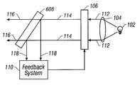
- FIG. 1shows one embodiment of an illumination system using optical feedback to produce an illumination light at one or more predetermined intensities in accordance with the present invention.
- the illumination system in FIG. 1includes a light source 102 , a lens 104 , an electrically controllable optical filter 106 , a light deflector 108 , and a feedback system 110 .
- the light source 102 shown in FIG. 1generates light in the visible bandwidth.
- This lightincludes the primary color components (e.g., red, green, and blue bandwidth light).
- light source 102is a single light source that continuously emits, the red, green, and blue bandwidth components.
- light source 102may include three individual light sources each continuously emitting one of the red, green, and blue bandwidth light.
- light source 102whether a single light source or three individual light sources, may sequentially emit red, green, and blue bandwidth light.
- the light sourcescould be lasers.
- lens 104In the embodiment shown in FIG. 1, light emitted by light source 102 is collimated by lens 104 into collimated or parallel light 112 .
- Collimating lens 104may be defined by a traditional optical element or system of lens and/or mirror elements formed from glass, plastic, etc. This embodiment of lens 104 is static in nature. Alternatively, lens 104 may take embodiment in one or more electrically switchable holographic optical elements described in copending U.S. patent application Ser. No. 09/366,449 entitled Pancake Window Display System Employing One Or More Switchable Holographic Optical Elements filed Aug. 3, 1999, which is incorporated herein by reference.
- Collimated light 112 transmitted by lens 104falls incident upon electrically controllable optical filter 106 .
- Filter 106operates to filter collimated light 112 in accordance with one or more feed back control signals generated by feedback system 110 .
- Filtered light 114 emitted by filter 106falls incident on deflector 108 which, in turn, deflects all or a portion of filtered light 114 to feedback system 110 .
- Filtered light 114 which is not deflectedemits from deflector 108 as illumination light 116 for illuminating some object.
- Deflector 108may be a static device that continuously deflects a portion of filtered light 114 incident thereon to feedback system 110 .
- deflector 108may be embodied in one or more electrically switchable holographic optical elements which continuously deflect a portion of the filtered light 114 incident thereon or which deflects a portion or all of filtered light 114 incident thereon to feedback system 110 at predetermined intervals in time.
- Feedback system 110receives deflected light 118 from deflector 108 and in response thereto, generates one or more feedback control signals which control one or more of the filtering characteristics of filter 106 .
- feedback system 110functions to measure the intensity of deflected light 118 , continuously or at discrete intervals, to determine if the intensity of deflected light 118 is at one or more predetermined intensities. More particularly, the intensity of deflected light 118 at a point in time is compared by feedback system 110 to a predetermined intensity. If deflected light 118 intensity is equal or substantially equal to the predetermined intensity, then filtered light 114 and illumination light 116 are presumed to have intensities equal or substantially equal to predetermined values, respectively.
- feedback systemdetects the deviation and adjusts the one or more control signals provided to control filter 106 which, in turn, adjusts the filter 106 until deflected light 118 returns to its predetermined intensity.
- Feedback system 110is described above as controlling the filtering characteristics of filter 106 as a function of the intensity of a portion of filtered light 112 .
- the present inventionshould not be limited thereto. Rather, the present invention contemplates alternative embodiments in which, for example, a feedback system controls a filter in response to measuring and comparing the intensity of all or substantially all of the filtered light 114 at predetermined intervals of time.
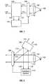
- FIG. 2shows an alternative embodiment of an illumination system using optical feedback to maintain an illumination light output at one or more predetermined intensities in accordance with the present invention.
- the embodiments shown in FIGS. 1 and 2operate in similar manner. Whereas FIG. 1 shows a transmissive type illumination system, FIG. 2, in contrast, shows as a reflective type illumination system.
- the illumination systemincludes a light source 102 , a lens 104 , an electrically controllable optical filter 206 , deflector 108 , and feedback system 110 .
- the system shown in FIG. 2employs many of the same elements of FIG. 1 . Common reference numbers are used to identify common elements in the systems shown in FIGS. 1 and 2.
- filter 206receives and filters collimated light 112 in accordance with control signals received from feedback system 110 .
- filter 106emits filtered light 114 from a surface opposite to that which receives the collimated light 112
- filter 206 of FIG. 2emits filtered light 114 from the same surface that receives the collimated light 112 .
- Deflector 108deflects a portion or all of the filtered light 114 . This deflected light is provided to feedback system 110 . The remaining portion of filtered light 114 not deflected, emits from deflector 108 as illumination light 116 .
- Feedback system 110 shown in FIG. 2operates in a manner substantially similar to that described with reference to FIG. 1 .
- the feedback system in FIG. 2receives deflected light 118 and generates one or more feedback control signals that control filter 206 .
- Feedback system 110measures deflected light 118 to determine if it equals or substantially equals one or more predetermined intensities.
- the one or more predetermined intensities in this embodimentmay differ from the one or more predetermined intensities employed in the system shown in FIG. 1 .
- Filters 106 and 206filter collimated light 112 by removing or reducing light energy or intensity in one or more select bandwidth components thereof.
- filters 106 and 206at any given point in time, remove all or substantially all of the intensity of two of the red, green, and blue bandwidth components of collimated light 112 while variably reducing the intensity in the remaining bandwidth component. The amount by which the remaining bandwidth component is reduced depends on the target intensity of the illumination light 116 .
- filters 106 and 206in accordance with a first set of control signals generated by feedback system 110 , remove all or substantially all of the green and blue bandwidth components from collimated light 112 while variably reducing the red bandwidth component thereof.
- filters 106 and 206emit a variable portion of the red bandwidth component of collimated light 112 as filtered light 114 .
- Filtered light 114may contain trace elements of blue or green bandwidth components of collimated light 112 .
- the emitted red bandwidth filtered light 114is measured by feedback system 110 via deflected light 118 .
- the emitted red bandwidth filtered light 114should have an intensity equal to or substantially equal to a first predetermined value. If the intensity of the red bandwidth filtered light 114 deviates from the first predetermined value, feedback system 110 generates a new set of first control signals. Feedback system 110 corrects intensity deviations by adjusting the filtering characteristics of filters 106 and 206 using the new first set of feedback control signals.
- filters 106 and 206In a second stage of the cycle subsequent to the first stage, filters 106 and 206 , in accordance with a second set of control signals generated by feedback system 110 , remove all or substantially all of the red and blue bandwidth components from collimated light 112 while variably reducing the green bandwidth component thereof. Thus, filters 106 and 206 emit a variable portion of the green bandwidth component of collimated light 112 as filtered light 114 . Filtered light 114 may contain trace elements of blue or red bandwidth components of collimated light 112 .
- the emitted green bandwidth filtered light 114is measured by feedback system 110 via deflected light 118 .
- the emitted green bandwidth filtered light 114should have an intensity equal to or substantially equal to a second predetermined value. If the intensity of the green bandwidth filtered light 114 deviates from the second predetermined value, feedback system 110 generates a new set of second control signals. Feedback system 110 corrects intensity deviations by adjusting the filtering characteristics of filters 106 and 206 using the new second set of feedback control signals.
- filters 106 and 206In a third stage of the cycle subsequent to the second stage, filters 106 and 206 , in accordance with a third set of control signals generated by feedback system 110 , remove all or substantially all of the green and red bandwidth components from collimated light 112 while variably reducing the blue bandwidth component thereof. Thus, filters 106 and 206 emit a variable portion of the blue bandwidth component of collimated light 112 as filtered light 114 . Filtered light 114 may contain trace elements of red or green bandwidth components of collimated light 112 .
- the emitted blue bandwidth filtered light 114is measured by feedback system 110 via deflected light 118 .
- the emitted blue bandwidth filtered light 114should have an intensity equal to or substantially equal to a third predetermined value. If the intensity of the blue bandwidth filtered light 114 deviates from the third predetermined value, feedback system 110 generates a new set of third control signals. Feedback system 110 corrects intensity deviations by adjusting the filtering characteristics of filters 106 and 206 using the new third set of feedback control signals.
- filters 106 and 206remove all or substantially all of the energy in one of the red, green, and blue bandwidth components of collimated light 112 while variably reducing the intensity contained in the remaining two bandwidth components. Again, the filtering is performed in a repeated cycle.
- filters 106 and 206in accordance with a first set of control signals generated by feedback system 110 remove all or substantially all of the blue bandwidth component from collimated light 112 while variably reducing the red and green bandwidth components of collimated light 112 .
- the first set of control signals in this modeis distinct from the first set of control signals employed in the preferred mode.
- filters 106 and 206emit a variable portion of the red and green bandwidth components of collimated light 112 as filtered light 114 .
- Filtered light 114may contain trace elements of blue bandwidth light.
- the emitted red and green bandwidth filtered light 114in combination, should have an intensity equal to or substantially equal to a first predetermined value.
- the first predetermined value used in this modemay be different from the first predetermined value used in the preferred mode. If the intensity of the red and green bandwidth filtered light 114 deviates from the first predetermined value, the deviation is detected by feedback system 110 via deflected light 118 , and feedback system 110 generates a new set of first control signals. Feedback system 110 corrects the deviation by adjusting filters 106 and 206 using the new first set of feedback control signals.
- filters 106 and 206in accordance with a second set of control signals generated by feedback system 110 remove all or substantially all of the green bandwidth component from collimated light 112 while variably reducing the red and blue bandwidth components of collimated light 112 .
- the second set of control signals in this modeis distinct from the second set of control signals employed in the preferred mode.
- filters 106 and 206emit a variable portion of the red and blue bandwidth components of collimated light 112 as filtered light 114 .
- Filtered light 114may contain trace elements of green bandwidth light.
- the emitted red and blue bandwidth filtered light 114in combination, should have an intensity equal to or substantially equal to a second predetermined value.
- the second predetermined value used in this modemay be different from the second predetermined value used in the preferred mode. If the intensity of the red and blue bandwidth filtered light 114 deviates from the second predetermined value, the deviation is detected by feedback system 110 via deflected light 118 , and feedback system 110 generates a new set of second control signals. Feedback system 110 corrects the deviation by adjusting filters 106 and 206 using the new second set of feedback control signals.
- filters 106 and 206in accordance with a third set of control signals generated by feedback system 110 remove all or substantially all of the red bandwidth component from collimated light 112 while variably reducing the blue and green bandwidth components of collimated light 112 .
- the third set of control signals in this modeis distinct from the third set of control signals employed in the preferred mode.
- filters 106 and 206emit a variable portion of the blue and green bandwidth components of collimated light 112 as filtered light 114 .
- Filtered light 114may contain trace elements of red bandwidth light.
- the emitted blue and green bandwidth filtered light 114in combination, should have an intensity equal to or substantially equal to a third predetermined value.
- the third predetermined value used in this modemay be different from the third predetermined value used in the preferred mode. If the intensity of the blue and green bandwidth filtered light 114 deviates from the third predetermined value, the deviation is detected by feedback system 110 via deflected light 118 , and feedback system 110 generates a new set of third control signals. Feedback system 110 corrects the deviation by adjusting filters 106 and 206 using the new third set of feedback control signals.
- filters 106 and 206operate to variably reduce the light intensity contained in all three of the red, green, and blue bandwidth components of collimated light 112 in accordance with one feedback control signal generated by feedback system 110 .
- filters 106 and 206emit a variable portion of each of the red, green and blue bandwidth components of collimated light 112 as filtered light 114 .
- the red, green, and blue bandwidth filtered light 114 emitted by filters 106 and 206should have an intensity equal to or substantially equal to a predetermined value. If the intensity of combined red, green, and blue bandwidth filtered light 114 deviates from the predetermined value, the deviation is detected by feedback system 110 via deflected light 118 .
- Feedback system 110corrects the deviation by adjusting filters 106 and 206 using a new control signal generated by feedback system 110 .
- FIG. 3shows one embodiment of feedback system 110 . More particularly, FIG. 3 shows feedback system having a lens 302 , a light detector 304 , and a control circuit 306 .
- lens 302is a conventional collection lens that focuses deflected light 118 .
- the conventional lens 302may take form in glass, plastic or other static material.
- lens 302may take form in one or more electrically switchable holographic optical elements that record a collection lens therein.
- a collection lens embodied in one more electrically switchable holographic optical elementsis described in U.S. patent application Ser. No. 09/313,431 entitled Switchable Holographic Optical System, filed May 17, 1999 which is incorporated herein by reference.
- control circuit 306could be extended to provide signals for controlling a collection lens 302 embodied in one or more electrically switchable holographic optical elements.
- Lens 302collects or focuses deflected light 118 onto detector 304 .
- Light detector 304takes form in any one of several types of light detectors including photo capacitors, photo diodes, etc. Essentially, light detector 304 generates an output signal as a function of the intensity of deflected light 118 incident thereon. The magnitude of the detector's output signal corresponds to the intensity of light detected. This correspondence can be linear. The detector 304 may continuously generate an output signal as a function of the light intensity incident thereon. Alternatively, the detector 304 may detect deflected light and generate a corresponding output signal at predetermined intervals in accordance with a control or sample signal received from control circuit 306 .
- Deflected light 118may contain one or more of the red, green, or blue bandwidths depending on the mode in which filter 106 or 206 operates.
- deflected light 118includes only one of the red, green, or blue bandwidths. Trace components of the remaining bandwidths may be present in the deflected light 118 . In this embodiment, deflected light 118 cycles through the red, green, and blue bandwidth components.
- deflected light 118includes only two of the red, green, or blue bandwidths. Trace components of the remaining bandwidth may be present in the deflected light 118 . In this embodiment, deflected light 118 cycles through combinations of two of the red, green, and blue bandwidth components. In the embodiment where filters 106 and 206 operate to variably reduce the energy contained in all three of the red, green, and blue bandwidth components of collimated light 112 , deflected light 118 contains all three of the bandwidth components.
- Control circuit 306functions in a variety of modes corresponding to the variety of modes in which filter 106 or 206 operates.
- Control circuit 306includes three output registers (an output register associated with each of the red, green, and blue bandwidths, all three of which are not shown in the Figures) that, in combination, output the control signals used to control filter 106 or 206 .
- Control circuit 304will be described with reference to the mode described above in which filter 106 or 206 removes all or substantially all of the energy of two of the red, green, and blue bandwidth components of collimated light 112 while variably reducing the energy in the remaining bandwidth component, it being understood that control circuit 106 or 206 can operate in other modes.
- the red bandwidth associated output registerstores a red bandwidth control signal for controlling the amount of red bandwidth light removed by filter 106 or 206 .
- the red bandwidth output registerstores either a first red bandwidth control signal that causes filter 106 or 206 to remove all or substantially all of the red bandwidth component from collimated light 112 , or a second red bandwidth control signal that causes filter 106 or 206 to remove a variable portion of the red bandwidth component of collimated light 112 .
- the first red bandwidth control signalis stored in a first red bandwidth control register while the second red bandwidth control signal is stored in a second red bandwidth control register.
- the green bandwidth associated output registerstores a green bandwidth control signal for controlling the amount of green bandwidth light removed by filter 106 or 206 .
- the green bandwidth output registerstores either a first green bandwidth control signal that causes filter 106 or 206 to remove all or substantially all of the green bandwidth component from collimated light 112 , or a second green bandwidth control signal that causes filter 106 or 206 to remove a variable portion of the green bandwidth component of collimated light 112 .
- the first green bandwidth control signalis stored in a first green bandwidth control register while the second green bandwidth control signal is stored in a second green bandwidth control register.
- the blue bandwidth associated output registerstores a blue bandwidth control signal for controlling the amount of blue bandwidth light removed by filter 106 or 206 .
- the blue bandwidth output registerstores either a first blue bandwidth control signal that causes filter 106 or 206 to remove all or substantially all of the blue bandwidth component from collimated light 112 , or a second blue bandwidth control signal that causes filter 106 or 206 to remove a variable portion of the blue bandwidth component of collimated light 112 .
- the first blue bandwidth control signalis stored in a first blue bandwidth control register while the second blue bandwidth control signal is stored in a second blue bandwidth control register.
- the contents of the three output registersare maintained by the control circuit 306 and depend on the cycle stage in which filter 106 or 206 is operating at the time.
- the red bandwidth output registerstores the second red bandwidth control signal
- the green and blue bandwidth output registersstore the first green and first blue bandwidth control signals, respectively.
- the green bandwidth output registerstores the second red bandwidth control signal
- the red and blue bandwidth output registersstore the first red and first blue bandwidth control signals, respectively.
- the blue bandwidth output registerstores the second blue bandwidth control signal
- the green and red bandwidth output registersstore the first green and first red bandwidth control signals, respectively.
- the second red, green, and blue bandwidth control signals stored in the second red, green, and blue bandwidth control registers, respectively,may change during operation of the illumination system to offset intensity deviations in deflected light 118 .
- the intensity of deflected light 118is checked during each stage of the three-stage cycle.
- the deflected light 118includes essentially, only red bandwidth light.
- a detector output signalis generated that is proportional to the red bandwidth deflected light 118 .
- control circuit 306compares the detector output signal to a first predetermined value previously stored in memory of control circuit 306 .
- the second red bandwidth control signalis left unchanged, and filter 106 or 206 , in the first stage of the next cycle, is provided with the same second red bandwidth control signal in addition to the first green and first blue bandwidth control signals.
- the second red bandwidth control signal, the first green bandwidth control signal and the first blue bandwidth control signalcollectively constitute the first set of control signals mentioned above. If the detector output signal does not equal or substantially equal the first predetermined value, then the second red bandwidth control signal is updated accordingly. In next first stage, the updated second red bandwidth control signal is provided to filter 106 or 206 along with the first green and blue bandwidth control signals, all three signals being provided as the new first set control signals.
- the intensity of red bandwidth filtered light emitted by filter 106 or 206 in response to receiving the new set of first control signalsis different when compared to the intensity of filtered red bandwidth light emitted by filter 106 or 206 in response to receiving the first set of control signals.
- the first red bandwidth control signalmay be updated in a number of ways. More particularly, the first red bandwidth control signal may be increased or decreased by a set amount depending on whether the detector output signal is smaller or greater than the first predetermined value. Alternatively, a difference can be calculated between the detector output signal and the first predetermined value, and the first red bandwidth control signal may be increased or decreased by an amount proportional to the difference. In this embodiment, the intensity of the deflected light 118 is checked during each first stage of each cycle.
- the intensity of deflected light 118is also checked during the second stage of the three-stage cycle in essentially the same way deflected light 118 is checked in the first stage.
- the deflected light 118includes essentially, only green bandwidth light.
- a detector output signalis generated that is proportional to the green bandwidth deflected light 118 .
- control circuit 306compares the detector output signal to a second predetermined value previously stored in memory of control circuit 306 .
- the second green bandwidth control signalis left unchanged, and filter 106 or 206 , in the second stage of the next cycle, is provided with the same second green bandwidth control signal in addition to the first red and first blue bandwidth control signals.
- the second green bandwidth control signal, the first red bandwidth control signal and the first blue bandwidth control signalcollectively constitute the second set of control signals mentioned above. If the detector output signal does not equal or substantially equal the second predetermined value, then the second green bandwidth control signal is updated accordingly. In next second stage, the updated second green bandwidth control signal is provided to filter 106 or 206 along with the first red and blue bandwidth control signals, all three signals being provided as the new second set control signals.
- the intensity of green bandwidth filtered light emitted by filter 106 or 206 in response to receiving the new set of second control signalsis different when compared to the intensity of filtered green bandwidth light emitted by filter 106 or 206 in response to receiving the second set of control signals.
- the second green bandwidth control signalmay be updated in a manner similar to the manner in which the second red bandwidth control signal as updated. More particularly, the second green bandwidth control signal may be increased or decreased by a set amount depending on whether the detector output signal is smaller or greater than the second predetermined value. Alternatively, a difference can be calculated between the detector output signal and the second predetermined value, and the second green bandwidth control signal may be increased or decreased by an amount proportional to the difference. In this embodiment, the intensity of the deflected light 118 is checked during each second stage of each cycle.
- the intensity of deflected light 118is checked during the third stage of the three-stage cycle in essentially the same way deflected light 118 is checked in the first and second stages.
- the deflected light 118includes essentially, only blue bandwidth light.
- a detector output signalis generated that is proportional to the blue bandwidth deflected light 118 .
- control circuit 306compares the detector output signal to a third predetermined value previously stored in memory of control circuit 306 .
- the second blue bandwidth control signalis left unchanged, and filter 106 or 206 , in the third stage of the next cycle, is provided with the same second blue bandwidth control signal in addition to the first green and first red bandwidth control signals.
- the second blue bandwidth control signal, the first green bandwidth control signal and the first red bandwidth control signalcollectively constitute the third set of control signals mentioned above. If the detector output signal does not equal or substantially equal the third predetermined value, then the second blue bandwidth control signal is updated accordingly. In next third stage, the updated second blue bandwidth control signal is provided to filter 106 or 206 along with the first green and red bandwidth control signals, all three signals being provided as the new third set control signals.
- the intensity of blue bandwidth filtered light emitted by filter 106 or 206 in response to receiving the new set of third control signalsis different when compared to the intensity of filtered blue bandwidth light emitted by filter 106 or 206 in response to receiving the third set of control signals.
- the second blue bandwidth control signalmay be updated in the same way that the second red bandwidth and second green bandwidth control signals are updated. More particularly, the second blue bandwidth control signal may be increased or decreased by a set amount depending on whether the detector output signal is smaller or greater than the third predetermined value. Alternatively, a difference can be calculated between the detector output signal and the third predetermined value, and the second blue bandwidth control signal may be increased or decreased by an amount proportional to the difference. In this embodiment, the intensity of the deflected light 118 is checked during each third stage of each cycle.
- Filters 106 and 206are solid state systems. Filters 106 and 206 may take form in one of several embodiments. More particularly, Filters 106 and 206 may be embodied in one or more layers of conventional liquid crystal material. Alternatively, Filters 106 and 206 may be embodied in conventional interference filters combined with electronically controllable neutral density filters based on liquid crystal.
- U.S. patent application Ser. No. 09/478,150 entitled Optical Filter Employing Holographic Optical Elements And Image Generating System Incorporating The Optical Filterfiled Jan 5, 2000, which is incorporated herein by reference, discloses several embodiments of the filters 106 and 206 shown in FIGS. 1 and 10.
- Filters 106 or 206may be formed of one or more electrically switchable holographic optical elements each of which can independently operate in an active state or an inactive state in accordance with a control signal.
- each electrically switchable holographic optical elementIn the inactive state, each electrically switchable holographic optical element passes collimated light 112 without substantial alteration.
- each electrically switchable holographic optical elementdiffracts a select bandwidth (e.g., red bandwidth) of collimated light 112 while passing the remaining portions (e.g., green and blue bandwidths) of collimated light 112 without substantial alteration.
- the diffracted lightemerges from the electrically switchable holographic optical element as zero order and first order diffracted light having an angle therebetween.
- the zero order-diffracted componentemerges from the electrically switchable holographic optical element normal to the emitting surface thereof.
- the electrically switchable holographic optical elementmay diffract the select bandwidth into higher order components.
- this disclosurewill presume that all of the select bandwidth is diffracted into zero order or first order diffracted light. Further, the amount of light energy contained in the zero order and first order diffracted components depends on a magnitude of a voltage of the control signal applied to the electrically switchable holographic optical element as will be more fully described below.
- FIG. 4shows a cross sectional view of one embodiment of an electrically switchable holographic optical element that can be used in filters 106 or 206 .
- the switchable holographic optical element of FIG. 4includes a pair of substantially transparent and electrically non-conductive layers 402 , a pair of substantially transparent and electrically conductive layers 404 , and a switchable holographic layer 406 formed, in one embodiment, from the polymer dispersed liquid crystal material described in U.S. patent application Ser. No. 09/478,150 which, as noted above, is incorporated herein by reference.
- the substantially transparent, electrically non-conductive layers 402comprise glass
- the substantially transparent, electrically conductive layers 404comprise indium tin oxide (ITO).
- An anti-reflection coating(not shown) may be applied to selected surfaces of the switchable holographic optical element, including surfaces of the ITO and the electrically nonconductive layers, to improve the overall transmissive efficiency of the optical element and to reduce stray light. As shown in the embodiment of FIG. 4, all layers 402 - 406 are arranged like a stack of pancakes on a common axis 408 .
- Layers 402 - 406may have substantially thin cross-sectional widths, thereby providing a substantially thin aggregate in cross section. More particularly, switchable holographic layer 406 may have a cross-sectional width of 5-12 microns (the precise width depending on a spectral bandwidth and required diffraction efficiency), while glass layers 402 may have a cross-sectional width of 0.4-0.8 millimeters. Obviously, ITO layers 404 must be substantially thin to be transparent. It should be noted that holographic layers may be deposited on thin plastic substrates. The plastic substrates may also be flexible.
- the switchable holographic optical elementWith ITO layers 404 coupled to a first voltage, an electric field is established within the switchable holographic layer 406 and the switchable holographic element operates in the inactive state described above. However, when the ITO layers 404 are coupled to a voltage below the first voltage, the switchable holographic optical element operates in the active state as described above. When active, the electrically switchable holographic optical element diffracts, for example, the red bandwidth component of collimated incident light 112 while passing the remaining components of collimated incident light 112 , including green and blue bandwidth components, without substantial alteration. The diffracted light emerges as zero order and first order components. The intensity of light in the first and zero order components depends on the magnitude of the voltage applied to the ITO layers 404 .
- a reduction of the voltage applied to the ITO layers 404reduces the energy in the zero-order diffracted component while simultaneously and proportionately increasing the energy in the first diffracted component.
- linearly lowering the voltage applied to the ITO layers 404causes a linear transfer of light energy (i.e., intensity) from the zero order to the first order components.
- Either the zero order or the first order diffracted lightcould be used as filtered light 114 shown in FIG. 1 .
- the first order diffracted lightcould be used as filtered light 114 shown in FIG. 2 .
- the switchable holographic optical element shown in FIG. 4may be reflective or transmissive type.
- FIG. 4shows switchable holographic optical element with oppositely facing front and back surfaces 410 and 412 .
- collimated light 112falls incident on the front surface 410 at normal incidence angle. Note that it is not essential for the incident light to be at normal incidence, althought this is likely to be the preferred option in most applications
- the switchable holographic optical elementis configured as transmissive type, the zero order and first order diffracted light components emerge from back surface 412 .
- the electrically switchable holographic optical elementis configured as reflective type hologram
- the first order diffracted light componentemerges from front surface 410 while the zero order diffracted component emerges from the back surface.
- Either one or more reflective or transmissive type electrically switchable holographic optical elementscould be used in the filter 106 of FIG. 1 .
- Filter 206 shown in FIG. 2may employ one or more reflective type electrically switchable holographic optical elements.
- Switchable holographic layer 406records a hologram using conventional techniques.
- the resulting hologramis characterized by a high diffraction efficiency and a fast rate at which the optical element can be switched between active and inactive states.
- the recorded hologramcan be switched from a diffracting state to a transmitting state with the creation and elimination of the electric field mentioned above.
- the holograms recorded in the holographic layer 406would be Bragg (also know as thick or volume phase) type in order to achieve high diffraction efficiency.
- Raman-Nath or thin phase type hologramsmay also be employed.
- the hologram recorded in switchable holographic layer 406can be based on PDLC materials described in the 09/478,150 application which is incorporated herein by reference.
- the hologramresults in an interference pattern creating by recording beams, i.e., a reference beam and an object beam, within layer 406 .
- Interaction of the laser light with the PDLC materialcauses photopolymerization.
- Liquid crystal dropletsbecome embedded in the dark regions of the fringe patterns that are formed by the intersection of the recording beams during the recording process.
- the recording materialmay be a polymer dispersed liquid crystal mixture which undergoes phase separation during the recording process, creating regions densely populated by liquid crystal microdroplets, interspersed by regions of clear photopolymer.
- the liquid crystal dropletsWhen a voltage of sufficient magnitude is supplied to ITO layers 404 , the liquid crystal droplets reorient and change the refractive index of the hologram layer 406 thereby essentially erasing the hologram recorded therein so that all collimated light 112 incident thereon passes without noticeable alteration.
- the material used within layer 406is configured to operate at a high switching rate (e.g., the material can be switched in tens of microseconds, which is very fast when compared with conventional liquid crystal display materials) and a high diffraction efficiency.
- FIG. 5shows one embodiment of filter 106 or 206 employing three separate electrically switchable holographic optical elements 502 R, 502 G, and 502 B.
- Each of the electrically switchable holographic optical elements 502 R through 502 Bis configured to diffract a select bandwidth of collimated light 112 incident thereon when the element operates in the active state. More particularly, electrically switchable holographic optical elements 502 R is configured to diffract red bandwidth light when active while passing the remaining components of collimated light 112 without substantial alteration. Similarly the electrically switchable holographic optical elements 502 G and 502 B are configured to diffract green bandwidth and blue bandwidth components, respectively, of collimated light 112 when active while passing the remaining components of collimated light 112 without substantial alteration. Each of the electrically switchable holographic optical elements 502 R through 502 B pass substantially all bandwidths of collimated light 112 without substantial alteration when operating in the inactive state.
- Each of the three electrically switchable holographic optical elements 502 R through 502 Gis activated or deactivated in accordance with a respective feedback control signal provided by feedback system 110 shown in FIG. 3 .
- each of the optical elementsdiffracts a select bandwidth of collimated light 112 into zero and first order diffracted components.
- the intensity of the light contained in the zero and first order diffracted componentsdepends on the magnitude of the feedback control signal provided to the electrically switchable holographic optical element.
- each of the electrically switchable holographic optical elements 502 R, 502 G, and 502 Breceives the first or second red bandwidth control signals, the first or second green bandwidth control signals, and the first or second blue bandwidth control signals, respectively, described above. More particularly, the first or second red bandwidth control signals are selectively applied to the ITO layers of electrically switchable holographic optical element 502 R, the first or second green bandwidth control signals are selectively applied to the ITO layers of electrically switchable holographic optical element 502 G, and the first or second blue bandwidth control signals are selectively applied to the ITO layers of electrically switchable holographic optical element 502 B.
- Filter 500 of FIG. 5may be configured as transmissive or reflective. Whether transmissive or reflective, filter 500 operates in one of several distinct modes in accordance with feedback control signals provided thereto.
- FIG. 5Aillustrates a reflective filter 500 configured operating in an additive mode.
- electrically switchable holographic optical element 502 Ris activated while electrically switchable holographic optical elements 502 G and 502 B are deactivated.
- collimated light 112passes through the deactivated electrically switchable holographic optical elements 502 B and 502 G without substantial alteration.
- activated electrically switchable holographic optical element 502 Rdiffracts the red bandwidth component of collimated light 112 into zero order and first order diffracted red bandwidth components.
- light 504 emerging from filter 500includes first order diffracted red bandwidth light and possibly trace elements of other bandwidth components of collimated light 112 .
- Light 506 emerging from filter 500in contrast includes the zero order diffracted red bandwidth light in addition to the blue and green bandwidth components of collimated light 112 , both of which pass through filter 500 without substantial alteration.
- Filter 500 in FIG. 5Ais shown diffracting red bandwidth light while substantially transmitting all green and blue bandwidth light.
- This operational mode of filter 500may result in response to filter 500 receiving the first set of control signals or the new first set of control signals during the first stage of the three stage cycle described above.
- the second or the updated second red bandwidth control signalis applied to the ITO layers of electrically switchable holographic optical element 502 R while the first green and blue bandwidth control signals are applied to the ITO layers of electrically switchable holographic optical elements 502 G and 502 B, respectively.
- the first green and blue bandwidth control signalscompletely deactivate electrically switchable holographic optical elements 502 G and 502 B, respectively.
- light 504constitutes filtered light 114 shown in FIG. 1, and the second or updated second red bandwidth control signals are generated by feedback system 110 in order to maintain light 504 (or filtered light 114 ) at the first predetermined intensity.
- Filter 500 in FIG. 5Amay also operate in the additive mode to diffract green bandwidth light while substantially transmitting all red and blue bandwidth light in response to receiving the second set of control signals or the new second set of control signals during the second stage of the three stage cycle described above. Additionally, filter 500 of FIG. 5A may operate in the additive mode to diffract blue bandwidth a light while substantially transmitting all red and green bandwidth light in response to receiving the third set of control signals or the new third set of control signals during the third stage of the three stage cycle described above.
- FIG. 5Billustrates filter 500 configured as a transmissive type operating in a subtractive mode.
- each electrically switchable holographic optical element 502 R through 502 Bis activated.
- each of electrically switchable holographic optical elements 502 R through 502 Bdiffract components of collimated light 112 .
- Electrically switchable holographic optical elements 502 G and 502 Bare fully activated in that all or substantially all of the energy contained in the green and blue bandwidth components, respectively, of collimated light 112 are diffracted into first order components 510 G and 510 B, respectively.
- Electrically switchable holographic optical element 502 Ris also activated. Electrically switchable holographic optical element 502 R diffracts the red bandwidth component of collimated light 112 into zero order and first order diffracted components. The first order diffracted red bandwidth light emits from filter 500 as first order diffracted red bandwidth light 510 R while the zero order red bandwidth component emits as light 512 . if electrically switchable holographic optical elements 502 G and 502 B operate at maximum theoretical diffraction efficiency, light 512 essentially contains only zero order diffracted red bandwidth light. In the preferred mode, light 512 is used as filtered light 114 as shown in FIG. 1 .
- Filter 500 in FIG. 5Bis shown diffracting all visible components of collimated light 112 .
- This operational mode of filter 500may result in response to filter 500 receiving the first set of control signals or the new first set of control signals during the first stage of the three stage cycle described above.
- the magnitudes of the first set of control signals and the new first set of control signals in this mode of operationare distinct from the first set of control signals and the new first set of control signals provided to filter 500 operating in the additive mode described above.
- the second or the updated second red bandwidth control signalis applied to the ITO layers of electrically switchable holographic optical element 502 R while the first green and blue bandwidth control signals are applied to the ITO layers of electrically switchable holographic optical elements 502 G and 502 B, respectively.
- the first green and blue bandwidth control signalscompletely activate electrically switchable holographic optical elements 502 G and 502 B, respectively.
- light 512constitutes filtered light 114 shown in FIG. 1, and the second or updated second red bandwidth control signals are generated by feedback system 110 in order to maintain light 512 (or filtered light 114 ) at the first predetermined intensity.
- Filter 500 in FIG. 5Bmay also operate in the subtractive mode to diffract all or substantially all of the red and blue bandwidth components of collimated light 112 into first order diffracted components while diffracting the green bandwidth component of collimated light 112 into zero order and first order diffracted components in response to filter 500 receiving the second set of control signals or the new second set of control signals during the second stage of the three stage cycle described above. Additionally, filter 500 of FIG.
- 5Boperate in the subtractive mode to diffract all or substantially all of the red and green bandwidth components of collimated light 112 into first order diffracted components while diffracting the blue bandwidth component of collimated light 112 into zero order and first order diffracted components in response to filter 500 receiving the third set of control signals or the new third set of control signals during the third stage of the three stage cycle described above.
- filter 500 of FIG. 5may be configured as a reflective type filter.
- FIG. 5Cillustrates a reflective type filter 500 operating in the additive mode.
- electrically switchable holographic optical element 502 Ris activated while electrically switchable holographic optical elements 502 G and 502 B are deactivated.
- collimated light 112passes through the deactivated electrically switchable holographic optical elements 502 B and 502 G without substantial alteration.
- activated electrically switchable holographic optical element 502 Rdiffracts the red bandwidth component of collimated light 112 into zero order and first order diffracted red bandwidth components.
- FIG. 5Cillustrates a reflective type filter 500 operating in the additive mode.
- electrically switchable holographic optical element 502 Ris activated while electrically switchable holographic optical elements 502 G and 502 B are deactivated.
- collimated light 112passes through the deactivated electrically switchable holographic optical elements 502 B and 502 G without substantial alteration.
- light 504 emerging from filter 500includes first order diffracted red bandwidth light and possibly trace elements of other bandwidth components of collimated light 112 .
- Light 706 emerging from filter 500in contrast includes the zero order diffracted red bandwidth light in addition to the blue and green bandwidth components of collimated light 112 , both of which pass through filter 500 without substantial alteration.
- Filter 500 in FIG. 5Cis shown diffracting red bandwidth light while substantially transmitting all green and blue bandwidth light.
- This operational mode of filter 500may result in response to filter 500 receiving the first set of control signals or the new first set of control signals during the first stage of the three stage cycle described above.
- the second or the updated second red bandwidth control signalis applied to the ITO layers of electrically switchable holographic optical element 502 R while the first green and blue bandwidth control signals are applied to the ITO layers of electrically switchable holographic optical elements 502 G and 502 B, respectively.
- the first green and blue bandwidth control signalscompletely deactivate electrically switchable holographic optical elements 502 G and 502 B, respectively.
- light 504constitutes filtered light 114 shown in FIG. 2, and the second or updated second red bandwidth control signals are generated by feedback system 110 in order to maintain light 504 (or filtered light 114 ) at the first predetermined intensity.
- Filter 500 in FIG. 5Cmay also operate in the additive mode to diffract green bandwidth light while substantially transmitting all red and blue bandwidth light in response to receiving the second set of control signals or the new second set of control signals during the second stage of the three stage cycle described above. Additionally, filter 500 of FIG. 5C may operate in the additive mode to diffract blue bandwidth light while substantially transmitting all red and green bandwidth light in response to receiving the third set of control signals or the new third set of control signals during the third stage of the three stage cycle described above.
- FIG. 5Dillustrates reflective type filter 500 operating in a subtractive mode.
- each electrically switchable holographic optical element 502 R through 502 Bis activated.
- each of electrically switchable holographic optical elements 502 R through 502 Bdiffract components of collimated light 112 .
- Electrically switchable holographic optical elements 502 G and 502 Bare fully activated in that all or substantially all of the energy contained in the green and blue bandwidth components, respectively, of collimated light 112 are diffracted into first order components 510 G and 510 B, respectively.
- Electrically switchable holographic optical element 502 Ris also activated. Electrically switchable holographic optical element 502 R diffracts the red bandwidth component of collimated light 112 into zero order and first order diffracted components. The first order diffracted red bandwidth light emits from filter 500 as first order diffracted red bandwidth light 510 R while the zero order red bandwidth component emits as light 512 . If electrically switchable holographic optical elements 502 G and 502 B operate at maximum theoretical diffraction efficiency, light 512 essentially contains only zero order diffracted red bandwidth light. In the preferred mode, light 512 is used as filtered light 114 shown in FIG. 1 .
- Filter 500 in FIG. 5Dis shown diffracting all visible components of collimated light 112 .
- This operational mode of filter 500may result in response to filter 500 receiving the first set of control signals or the new first set of control signals during the first stage of the three stage cycle described above.
- the magnitudes of the first set of control signals and the new first set of control signals in this mode of operationare distinct from the first set of control signals and the new first set of control signals provided to reflective type filter 500 operating in the additive mode described above.
- the second or the updated second red bandwidth control signalis applied to the ITO layers of electrically switchable holographic optical element 502 R while the first green and blue bandwidth control signals are applied to the ITO layers of electrically switchable holographic optical elements 502 G and 502 B, respectively.
- the first green and blue bandwidth control signalscompletely activate electrically switchable holographic optical elements 502 G and 502 B, respectively.
- light 512constitutes filtered light 114 shown in FIG. 1, and the second or updated second red bandwidth control signals are generated by feedback system 110 in order to maintain light 512 (or filtered light 114 ) at the first predetermined intensity.
- Filter 500 in FIG. 5Dmay also operate in the subtractive mode to diffract all or substantially all of the red and blue bandwidth components of collimated light 112 into first order diffracted components while diffracting the green bandwidth component of collimated light 112 into zero order and first order diffracted components in response to filter 500 receiving the second set of control signals or the new second set of control signals during the second stage of the three stage cycle described above. Additionally, filter 500 of FIG.
- 5Dmay also operate in the subtractive mode to diffract all or substantially all of the red and green bandwidth components of collimated light 112 into first order diffracted components while diffracting the blue bandwidth component of collimated light 112 into zero order and first order diffracted components in response to filter 500 receiving the third set of control signals or the new third set of control signals during the third stage of the three stage cycle described above.
- FIGS. 6 and 7show alternative embodiments of the system shown in FIG. 1 .
- deflector 108 of FIG. 1takes form in beam splitter 608 .
- deflector 108 of FIG. 1takes form in prism 708 .
- a beam splitter or prismcould also be employed as deflector 108 in the system shown in FIG. 2 .
- the deflectorwould use multilayer coatings to reflect some specified small portion of the incident light.
- FIGS. 8 and 9show alternative embodiments of the illumination system shown in FIG. 1 in which deflector 108 takes form in one or more electrically switchable holographic optical elements.
- the deflector 108 of FIG. 1is embodied in one or more transmissive electrically switchable holographic optical elements 808 .
- the deflector 108 in FIG. 1takes form in one or more reflective electrically switchable holographic optical elements 908 .
- Each of the one or more transmissive or reflective electrically switchable holographic optical elements shown in FIGS. 8 or 9may be controlled by feedback system 110 properly extended.
- deflectors 808 and or 908include three distinct electrically switchable holographic optical elements each one of which is individually operable to diffract one of the red, green, and blue bandwidths of filtered light 114 incident thereon.
- one of the electrically switchable holographic optical elements in deflectors 808 or 908when operating in the active state, diffracts red, blue, or green bandwidth components of light 114 while transmitting the remaining portions filtered light 114 without substantial alterations.
- filtered light 114which is subsequently diffracted by deflector 808 or 908 , falls incident on feedback control system 110 .
- deflectors 808 and 908are controlled by feedback system 110 .
- the deflectors 808 and 908 shown in FIGS. 8 and 9could be employed in similar fashion in the reflective type system shown in FIG. 2 .
- FIG. 10shows an alternative embodiment of the system shown in FIG. 1 using the filter 500 shown in FIG. 5 .
- control circuit 1002operates filter 500 between a sample mode and an illumination mode. In the illumination mode, control circuit 1002 generates control signals which operate filter 500 in the subtractive mode shown in FIG. 5 B. In the illumination mode, zero order diffracted light 506 is used as illumination light 116 . However, in the sample mode, control circuit 1002 operates filter 500 in the additive mode shown in FIG. 5 A. In the sample mode, circuit 1002 samples and compares the intensity of first order diffracted component 504 to one or more predetermined value. A variation in intensity between diffracted component 504 and the one or more predetermined values causes circuit 1002 adjust the control signals provided to filter 500 when filter 500 operates in the illumination mode.
- the illumination systems described abovemay have a number of applications. For example, it could be used to control color balance by compensating for color changes arising from light source temperature variation and color shift due to aging.
Landscapes
- Physics & Mathematics (AREA)
- Nonlinear Science (AREA)
- General Physics & Mathematics (AREA)
- Optics & Photonics (AREA)
- Chemical & Material Sciences (AREA)
- Mathematical Physics (AREA)
- Crystallography & Structural Chemistry (AREA)
- Dispersion Chemistry (AREA)
- Liquid Crystal (AREA)
Abstract
Description
Claims (30)
Priority Applications (1)
| Application Number | Priority Date | Filing Date | Title |
|---|---|---|---|
| US09/533,608US6507419B1 (en) | 1999-03-23 | 2000-03-23 | Illumination system using optical feedback |
Applications Claiming Priority (2)
| Application Number | Priority Date | Filing Date | Title |
|---|---|---|---|
| US12592699P | 1999-03-23 | 1999-03-23 | |
| US09/533,608US6507419B1 (en) | 1999-03-23 | 2000-03-23 | Illumination system using optical feedback |
Publications (1)
| Publication Number | Publication Date |
|---|---|
| US6507419B1true US6507419B1 (en) | 2003-01-14 |
Family
ID=26824097
Family Applications (1)
| Application Number | Title | Priority Date | Filing Date |
|---|---|---|---|
| US09/533,608Expired - Fee RelatedUS6507419B1 (en) | 1999-03-23 | 2000-03-23 | Illumination system using optical feedback |
Country Status (2)
| Country | Link |
|---|---|
| US (1) | US6507419B1 (en) |
| KR (1) | KR20010090432A (en) |
Cited By (7)
| Publication number | Priority date | Publication date | Assignee | Title |
|---|---|---|---|---|
| US20020191177A1 (en)* | 2001-05-25 | 2002-12-19 | Leica Microsystems Heidelberg Gmbh | Apparatus for determining a light power level, microscope, and method for microscopy |
| US20050237589A1 (en)* | 2003-09-23 | 2005-10-27 | Sbg Labs, Inc. | Optical filter employing holographic optical elements and image generating system incorporating the optical filter |
| WO2006102073A3 (en)* | 2005-03-18 | 2007-01-04 | Sbg Labs Inc | Spatial light modulator |
| US20080079945A1 (en)* | 2006-10-02 | 2008-04-03 | Flowers John P | Apparatus and Method to Quantify Laser Head Reference Signal Reliability |
| US20140300967A1 (en)* | 2011-11-07 | 2014-10-09 | Elbit Systems Of America, Llc | System and method for projecting synthetic imagery and scenic imagery using an optical component comprising a diffractive optical element pattern |
| CN109556708A (en)* | 2019-01-04 | 2019-04-02 | 北京环境特性研究所 | Larger Dynamic range scene imaging brightness measuring device for camera and imaging luminance measuring method |
| US20240310212A1 (en)* | 2023-03-14 | 2024-09-19 | BottleVin, Inc. | System and method for authenticating and classifying products using hyper-spectral imaging |
Citations (157)
| Publication number | Priority date | Publication date | Assignee | Title |
|---|---|---|---|---|
| US3807829A (en) | 1973-04-30 | 1974-04-30 | Hughes Aircraft Co | Extended-field holographic lens arrays |
| US4028725A (en) | 1976-04-21 | 1977-06-07 | Grumman Aerospace Corporation | High-resolution vision system |
| US4458981A (en) | 1982-01-26 | 1984-07-10 | Thomson-Csf | Holographic movie device |
| US4500163A (en) | 1981-07-29 | 1985-02-19 | The Singer Company | Holographic projection screen |
| DE3419098A1 (en) | 1984-05-23 | 1985-11-28 | Hartmut Dr. 8520 Erlangen Bartelt | Screen for spatial three-dimensional representation of images, graphics and other data |
| US4566031A (en) | 1984-02-16 | 1986-01-21 | The Holotronics Corporation | Spatial light modulation with application to electronically generated holography |
| US4669812A (en) | 1983-09-12 | 1987-06-02 | Hoebing John L | Method and apparatus for 3-D image synthesis |
| US4759596A (en) | 1984-08-30 | 1988-07-26 | Polaroid Corporation | Wavelength selective optical cavity including holographic filter layers |
| FR2610733A1 (en) | 1987-02-06 | 1988-08-12 | Ikeda Shigeru | IMAGE COMPOSER |
| US4790613A (en) | 1987-01-06 | 1988-12-13 | Hughes Aircraft Company | Holographic display panel for a vehicle windshield |
| US4799739A (en) | 1987-08-10 | 1989-01-24 | Advanced Dimensional Displays, Inc. | Real time autostereoscopic displays using holographic diffusers |
| US4807951A (en) | 1987-01-06 | 1989-02-28 | Hughes Aircraft Company | Holographic thin panel display system |
| US4830441A (en) | 1987-03-25 | 1989-05-16 | Kaiser Optical Systems | Holographic filter construction for protective eyewear |
| US4834473A (en) | 1986-03-26 | 1989-05-30 | The Babcock & Wilcox Company | Holographic operator display for control systems |
| US4834476A (en) | 1987-03-31 | 1989-05-30 | Massachusetts Institute Of Technology | Real image holographic stereograms |
| USH738H (en) | 1989-07-17 | 1990-02-06 | The United States Of America As Represented By The Secretary Of The Army | Switched holograms for reconfigurable optical interconnect |
| US4932731A (en) | 1986-11-14 | 1990-06-12 | Yazaki Corporation | Holographic head-up display apparatus |
| US4938568A (en) | 1988-01-05 | 1990-07-03 | Hughes Aircraft Company | Polymer dispersed liquid crystal film devices, and method of forming the same |
| EP0389123A2 (en) | 1989-03-21 | 1990-09-26 | Hughes Aircraft Company | A display system for multiviewer training simulators |
| US4981332A (en) | 1989-06-29 | 1991-01-01 | Hughes Aircraft Company | Dispersion-compensated windshield hologram virtual image display |
| US4993790A (en) | 1990-03-26 | 1991-02-19 | Rockwell International Corporation | Holographic lenticular screen stereoscopic avoinics display apparatus |
| US5011244A (en) | 1988-12-16 | 1991-04-30 | Hughes Aircraft Company | Holographic full color data retrieval and projection system |
| US5013141A (en) | 1985-02-21 | 1991-05-07 | Canon Kabushiki Kaisha | Liquid crystal light modulation device |
| US5014709A (en) | 1989-06-13 | 1991-05-14 | Biologic Systems Corp. | Method and apparatus for high resolution holographic imaging of biological tissue |
| US5024494A (en) | 1987-10-07 | 1991-06-18 | Texas Instruments Incorporated | Focussed light source pointer for three dimensional display |
| US5036385A (en) | 1986-03-07 | 1991-07-30 | Dimension Technologies, Inc. | Autostereoscopic display with multiple sets of blinking illuminating lines and light valve |
| US5035474A (en) | 1984-04-16 | 1991-07-30 | Hughes Aircraft Company | Biocular holographic helmet mounted display |
| US5044709A (en) | 1988-11-30 | 1991-09-03 | Hughes Aircraft Company | LED array polarized image source/0 degree hologram virtual image head up display |
| US5071209A (en) | 1990-05-07 | 1991-12-10 | Hughes Aircraft Company | Variable acuity non-linear projection system |
| US5093567A (en) | 1989-07-14 | 1992-03-03 | Gec-Marconi Limited | Helmet systems with eyepiece and eye position sensing means |
| US5093563A (en) | 1987-02-05 | 1992-03-03 | Hughes Aircraft Company | Electronically phased detector arrays for optical imaging |
| US5096282A (en) | 1988-01-05 | 1992-03-17 | Hughes Aircraft Co. | Polymer dispersed liquid crystal film devices |
| US5103323A (en) | 1990-04-18 | 1992-04-07 | Holographic Optics, Inc. | Multi-layer holographic notch filter |
| US5111313A (en) | 1989-08-10 | 1992-05-05 | Shires Mark R | Real-time electronically modulated cylindrical holographic autostereoscope |
| US5151724A (en) | 1991-01-30 | 1992-09-29 | Dan Kikinis | Dynamic holographic display with cantilever |
| US5153670A (en) | 1990-01-12 | 1992-10-06 | Physical Optics Corporation | Holographic lippmann-bragg filter in a spectroscopic system |
| US5175637A (en) | 1990-04-05 | 1992-12-29 | Raychem Corporation | Displays having improved contrast |
| GB2259213A (en) | 1991-08-29 | 1993-03-03 | British Aerospace | Variable resolution view-tracking display |
| US5221957A (en) | 1990-01-12 | 1993-06-22 | Physical Optics Corporation | Nonuniform holographic filter in a spectroscopic system |
| US5227898A (en) | 1991-12-02 | 1993-07-13 | Computer Sciences Corporation | Near real-time holographic display for remote operations |
| US5234449A (en) | 1992-07-16 | 1993-08-10 | Ethicon, Inc. | Suture clip with reduced hinge mass |
| EP0559435A1 (en) | 1992-03-05 | 1993-09-08 | International Business Machines Corporation | Improvements in holographic techniques |
| US5278532A (en) | 1987-09-14 | 1994-01-11 | Hughes Aircraft Company | Automotive instrument virtual image display |
| US5291314A (en) | 1990-07-27 | 1994-03-01 | France Telecom | Spatial light modulator device and a conoscopic holography system of large dynamic range including such a modulator device |
| US5299035A (en) | 1992-03-25 | 1994-03-29 | University Of Michigan | Holographic imaging through scattering media |
| US5305124A (en) | 1992-04-07 | 1994-04-19 | Hughes Aircraft Company | Virtual image display system |
| US5319492A (en) | 1991-05-23 | 1994-06-07 | Alcatel N.V. | Optical switch |
| EP0602813A1 (en) | 1992-12-17 | 1994-06-22 | International Business Machines Corporation | Hologram system and method |
| US5331149A (en) | 1990-12-31 | 1994-07-19 | Kopin Corporation | Eye tracking system having an array of photodetectors aligned respectively with an array of pixels |
| US5341229A (en) | 1988-07-14 | 1994-08-23 | Larry Rowan | Holographic display system |
| US5365354A (en) | 1990-10-02 | 1994-11-15 | Physical Optics Corporation | Grin type diffuser based on volume holographic material |
| US5379133A (en) | 1992-06-19 | 1995-01-03 | Atl Corporation | Synthetic aperture based real time holographic imaging |
| US5381253A (en) | 1991-11-14 | 1995-01-10 | Board Of Regents Of University Of Colorado | Chiral smectic liquid crystal optical modulators having variable retardation |
| US5414544A (en) | 1992-12-25 | 1995-05-09 | Sony Corporation | Display apparatus |
| US5418631A (en) | 1993-05-14 | 1995-05-23 | Kaiser Optical Systems, Inc. | Edge-lit holographic diffusers for flat-panel displays |
| US5424866A (en) | 1991-01-30 | 1995-06-13 | Kikinis; Dan | Dynamic holographic display with cantilever |
| EP0664495A1 (en) | 1994-01-21 | 1995-07-26 | Sharp Kabushiki Kaisha | Switchable holographic apparatus |
| US5440428A (en) | 1993-09-30 | 1995-08-08 | Hughes Aircraft Company | Automotive instrument 3-D virtual image display |
| US5455693A (en) | 1992-09-24 | 1995-10-03 | Hughes Aircraft Company | Display hologram |
| US5471327A (en) | 1993-05-14 | 1995-11-28 | Kaiser Optical Systems, Inc. | Holographic diffuser for back-lit display |
| US5497254A (en) | 1990-04-05 | 1996-03-05 | Seiko Epson Corporation | Optical apparatus including a liquid crystal modulator |
| US5506701A (en) | 1993-01-28 | 1996-04-09 | Dai Nippon Printing Co., Ltd. | Hologram color filter, liquid crystal display device using the same, and fabrication process of hologram color filter |
| US5521724A (en) | 1993-11-15 | 1996-05-28 | Shires; Mark R. | Real-time automultiscopic 3D video display using holographic optical elements (HOEs) |
| US5530565A (en) | 1992-11-30 | 1996-06-25 | Kaiser Optical Systems, Inc. | Holographic transmission bandpass filter |
| EP0720040A2 (en) | 1994-12-29 | 1996-07-03 | Sharp Kabushiki Kaisha | Illumination system and display device |
| US5535024A (en) | 1992-05-06 | 1996-07-09 | The United States Of America As Represented By The Secretary Of The Air Force | Photorefractive holographic interference novelty filter |
| US5537232A (en) | 1993-10-05 | 1996-07-16 | In Focus Systems, Inc. | Reflection hologram multiple-color filter array formed by sequential exposure to a light source |
| US5539542A (en) | 1991-06-19 | 1996-07-23 | France Telecom | Photorefractive device having an electro-optical material between two photoconductive materials |
| US5539544A (en) | 1992-02-18 | 1996-07-23 | Sextant Avionique | Holographic filter for protection from radiation, notably laser radiation |
| US5544143A (en) | 1994-06-14 | 1996-08-06 | Eastman Kodak Company | Read/write laser-detector-grating unit (LDGU) with an orthogonally-arranged focus and tracking sensor system |
| US5552912A (en) | 1991-11-14 | 1996-09-03 | Board Of Regents Of The University Of Colorado | Chiral smectic liquid crystal optical modulators |
| US5552916A (en) | 1990-09-07 | 1996-09-03 | Displaytech, Inc. | Diffractive light modulator |
| US5557283A (en) | 1991-08-30 | 1996-09-17 | Sheen; David M. | Real-time wideband holographic surveillance system |
| US5561537A (en) | 1992-09-30 | 1996-10-01 | Fujitsu Limited | Stereoscopic display method and apparatus |
| US5568313A (en) | 1992-08-18 | 1996-10-22 | Applied Physics Research, L.P. | Apparatus for providing autostereoscopic and dynamic images and method of manufacturing same |
| US5570139A (en) | 1994-05-13 | 1996-10-29 | Wang; Yu | Surface plasmon high efficiency HDTV projector |
| US5570208A (en) | 1992-08-21 | 1996-10-29 | Fujitsu Limited | Stereoscopic display method of hologram and its forming method and stereoscopic display apparatus |
| US5579026A (en) | 1993-05-14 | 1996-11-26 | Olympus Optical Co., Ltd. | Image display apparatus of head mounted type |
| US5581378A (en) | 1993-02-01 | 1996-12-03 | University Of Alabama At Huntsville | Electro-optical holographic display |
| US5589956A (en) | 1992-07-31 | 1996-12-31 | Canon Kabushiki Kaisha | Image display apparatus |
| US5589957A (en) | 1994-03-15 | 1996-12-31 | Fujitsu Limited | Stereoscopic display apparatus using cylindrical screen |
| US5594560A (en) | 1994-03-07 | 1997-01-14 | Motorola, Inc. | Display device comprising fluorescent enhanced reflective holographic illumination |
| US5606455A (en) | 1993-05-06 | 1997-02-25 | Dimension Technologies, Inc. | Autostereoscopic display with high power efficiency |
| US5608552A (en) | 1995-12-26 | 1997-03-04 | Hughes Electronics | Liquid crystal display having an off-axis full-color holographic filter |
| US5615186A (en) | 1991-06-04 | 1997-03-25 | International Business Machines Corporation | Multiple data surface data storage system with holographic filter element |
| US5615023A (en) | 1993-12-24 | 1997-03-25 | Hyundai Electronics Industrial Co., Ltd. | Head-up display for automobile |
| US5617225A (en) | 1992-07-20 | 1997-04-01 | Fujitsu Limited | Stereoscopic display apparatus and method |
| US5621547A (en) | 1990-11-23 | 1997-04-15 | Thomson-Csf | Illumination device and application to a display device |
| US5629784A (en) | 1994-04-12 | 1997-05-13 | Ois Optical Imaging Systems, Inc. | Liquid crystal display with holographic diffuser and prism sheet on viewer side |
| US5635947A (en) | 1993-08-16 | 1997-06-03 | Agency Of Industrial Science & Technology, Ministry Of International Trade & Industry | Eye movement tracking display |
| EP0777136A1 (en) | 1995-11-08 | 1997-06-04 | Victor Company Of Japan, Limited | Color filter and color image display apparatus employing the filter |
| US5640256A (en) | 1996-01-25 | 1997-06-17 | Board Of Trustees Of The Leland Stanfor Junior University | Dynamic multiple wavelength filter using a stratified volume holographic optical element |
| US5644369A (en) | 1995-02-24 | 1997-07-01 | Motorola | Switchable lens/diffuser |
| US5650865A (en) | 1995-03-21 | 1997-07-22 | Hughes Electronics | Holographic backlight for flat panel displays |
| EP0785457A2 (en) | 1996-01-17 | 1997-07-23 | Nippon Telegraph And Telephone Corporation | Optical device and three-dimensional display device |
| US5668648A (en) | 1991-11-26 | 1997-09-16 | Kabushiki Kaisha Toshiba | Computer-assisted holographic display apparatus |
| US5680231A (en) | 1995-06-06 | 1997-10-21 | Hughes Aircraft Company | Holographic lenses with wide angular and spectral bandwidths for use in a color display device |
| US5684498A (en) | 1995-06-26 | 1997-11-04 | Cae Electronics Ltd. | Field sequential color head mounted display with suppressed color break-up |
| US5692077A (en) | 1996-04-30 | 1997-11-25 | Wavefront Research, Inc. | Optical time shifter and routing system |
| US5696749A (en) | 1996-06-28 | 1997-12-09 | Eastman Kodak Company | Dual-wavelength optical recording head utilizing grating beam splitter and integrated laser and detectors |
| US5696552A (en) | 1992-09-30 | 1997-12-09 | Fujitsu Limited | Stereoscopic display apparatus |
| US5698343A (en) | 1994-07-05 | 1997-12-16 | The United States Of America As Represented By The Secretary Of The Air Force | Laser wavelength detection and energy dosimetry badge |
| US5703702A (en) | 1993-09-08 | 1997-12-30 | Crane; Patrick E. | Holographic synthesis |
| US5706067A (en) | 1995-04-28 | 1998-01-06 | International Business Machines Corporation | Reflective spatial light modulator array |
| US5708488A (en) | 1992-10-07 | 1998-01-13 | Matsushita Electric Industrial Co., Ltd. | Phase type spatial light modulator having an output substantially uniform in amplitude |
| US5709463A (en) | 1996-08-13 | 1998-01-20 | Delco Electronics Corporation | Backlighting for bright liquid crystal display |
| EP0821293A2 (en) | 1996-07-22 | 1998-01-28 | Dai Nippon Printing Co., Ltd. | Reflection type diffuse hologram, hologram for reflection hologram color filters, etc., and reflection type display device using such holograms |
| US5719690A (en) | 1996-05-31 | 1998-02-17 | International Business Machines Corporation | Photorefractive glass article |
| US5721630A (en) | 1996-03-12 | 1998-02-24 | Polaroid Corporation | High-efficiency reflective holographic diffuser and method for making thereof |
| US5721598A (en) | 1995-12-26 | 1998-02-24 | Hughes Electronics | High efficiency, high color purity, on-axis holographic color filter and full-color liquid crystal display |
| EP0825462A1 (en) | 1996-08-21 | 1998-02-25 | Sony Corporation | Holographic optical element process for its production and projection liquid crystal display apparatus using the element |
| EP0826986A1 (en) | 1996-08-21 | 1998-03-04 | Victor Company Of Japan, Limited | Color filter and color display apparatus |
| US5729366A (en) | 1993-12-23 | 1998-03-17 | Hyundas Electronics Industries Co., Ltd. | Heads-up display for vehicle using holographic optical elements |
| US5736958A (en) | 1990-10-29 | 1998-04-07 | Essex Corporation | Image synthesis using time sequential holography |
| US5739930A (en) | 1992-10-13 | 1998-04-14 | Fujitsu Limited | Display apparatus |
| US5744267A (en) | 1994-10-12 | 1998-04-28 | Arizona Board Of Regents Acting For And On Behalf Of University Of Arizona | Azo-dye-doped photorefractive polymer composites for holographic testing and image processing |
| US5745203A (en) | 1996-03-28 | 1998-04-28 | Motorola, Inc. | Liquid crystal display device including multiple ambient light illumination modes with switchable holographic optical element |
| US5748828A (en) | 1993-11-10 | 1998-05-05 | Alliedsignal Inc. | Color separating backlight |
| US5748272A (en) | 1993-02-22 | 1998-05-05 | Nippon Telegraph And Telephone Corporation | Method for making an optical device using a laser beam interference pattern |
| US5751243A (en) | 1990-10-29 | 1998-05-12 | Essex Corporation | Image synthesis using time sequential holography |
| US5760933A (en) | 1992-07-20 | 1998-06-02 | Fujitsu Limited | Stereoscopic display apparatus and method |
| US5764317A (en) | 1995-06-26 | 1998-06-09 | Physical Optics Corporation | 3-D volume visualization display |
| US5768242A (en) | 1996-04-05 | 1998-06-16 | The United States Of America As Representd By The Administrator Of The National Aeronautics And Space Administration | Apparatus and method for focusing a light beam in a three-dimensional recording medium by a dynamic holographic device |
| US5771320A (en) | 1996-04-30 | 1998-06-23 | Wavefront Research, Inc. | Optical switching and routing system |
| US5774175A (en) | 1992-10-14 | 1998-06-30 | Terumo Kabushiki Kaisha | Stereoscopic television |
| US5777742A (en) | 1993-03-11 | 1998-07-07 | Environmental Research Institute Of Michigan | System and method for holographic imaging with discernible image of an object |
| US5777760A (en) | 1996-05-10 | 1998-07-07 | Quantum Corporation | Position feedback system for volume holographic storage media |
| US5790284A (en) | 1993-06-01 | 1998-08-04 | Canon Kabushiki Kaisha | Display apparatus and displaying method for image display producing stereoscopic effect |
| EP0856768A2 (en) | 1997-01-31 | 1998-08-05 | Xerox Corporation | Broadband reflective display, and methods of forming the same |
| EP0856766A2 (en) | 1997-01-31 | 1998-08-05 | Xerox Corporation | Holographically formed reflective display, liquid crystal display and projection system and methods of forming the same |
| US5793503A (en) | 1992-01-03 | 1998-08-11 | Simian Company, Inc. | Methods of hologram construction using computer-processed objects |
| US5793504A (en) | 1996-08-07 | 1998-08-11 | Northrop Grumman Corporation | Hybrid angular/spatial holographic multiplexer |
| US5796498A (en) | 1992-02-14 | 1998-08-18 | Imperial College Of Science, Technology And Medicine | Holographic imaging |
| US5796499A (en) | 1997-02-28 | 1998-08-18 | Polaroid Corporation | Transmission holographic diffuser made and used to effect lateral color constancy in rear screen projection display systems |
| US5801799A (en) | 1996-12-23 | 1998-09-01 | Motorola, Inc. | Multi-directional liquid crystal phase spatial light modulator for enchanced display resolution |
| US5801793A (en) | 1994-04-21 | 1998-09-01 | Reveo, Inc. | Backlighting construction for use in computer-based display systems having direct and projection viewing modes of operation |
| US5801798A (en) | 1996-12-23 | 1998-09-01 | Motorola, Inc. | Fast speed liquid crystal phase spatial light modulator for enchanced display resolution |
| US5808589A (en) | 1994-08-24 | 1998-09-15 | Fergason; James L. | Optical system for a head mounted display combining high and low resolution images |
| US5808759A (en) | 1995-11-30 | 1998-09-15 | Mitsubishi Denki Kabushiki Kaisha | Projection type display including a holographic diffuser |
| US5808800A (en) | 1994-12-22 | 1998-09-15 | Displaytech, Inc. | Optics arrangements including light source arrangements for an active matrix liquid crystal image generator |
| US5815222A (en) | 1994-03-18 | 1998-09-29 | Fujitsu Limited | Apparatus for deflecting light, device for scanning light, device for reading information and device for stereoscopic display |
| US5822029A (en) | 1994-12-29 | 1998-10-13 | Sharp Kabushiki Kaisha | Illumination system and display device |
| US5825340A (en) | 1992-10-28 | 1998-10-20 | Sony Corporation | Head-mounted image display apparatus |
| US5825448A (en) | 1995-05-19 | 1998-10-20 | Kent State University | Reflective optically active diffractive device |
| US5825540A (en) | 1996-04-22 | 1998-10-20 | Raytheon Company | Autostereoscopic display and method |
| US5838403A (en) | 1996-02-14 | 1998-11-17 | Physical Optics Corporation | Liquid crystal display system with internally reflecting waveguide for backlighting and non-Lambertian diffusing |
| US5844709A (en) | 1997-09-30 | 1998-12-01 | The United States Of America As Represented By The Secretary Of The Navy | Multiple quantum well electrically/optically addressed spatial light modulator |
| US5844711A (en) | 1997-01-10 | 1998-12-01 | Northrop Grumman Corporation | Tunable spatial light modulator |
| US5867134A (en) | 1995-08-25 | 1999-02-02 | Alvelda; Phillip | VLSI visual display |
| US5880883A (en) | 1994-12-07 | 1999-03-09 | Canon Kabushiki Kaisha | Apparatus for displaying image recognized by observer as stereoscopic image, and image pick-up apparatus |
| US5886675A (en) | 1995-07-05 | 1999-03-23 | Physical Optics Corporation | Autostereoscopic display system with fan-out multiplexer |
| US5942157A (en) | 1996-07-12 | 1999-08-24 | Science Applications International Corporation | Switchable volume hologram materials and devices |
| US5946114A (en)* | 1994-06-17 | 1999-08-31 | Thomson-Csf | Optical filtering device and application to a liquid crystal projector |
| US5959704A (en) | 1996-02-08 | 1999-09-28 | Fujitsu Limited | Display device having diffraction grating |
| US5977935A (en) | 1993-08-12 | 1999-11-02 | Seiko Epson Corporation | Head-mounted image display device and data processing apparatus including the same |
| US6008781A (en) | 1992-10-22 | 1999-12-28 | Board Of Regents Of The University Of Washington | Virtual retinal display |
| US6023253A (en) | 1993-10-29 | 2000-02-08 | Canon Kabushiki Kaisha | Image displaying apparatus |
- 2000
- 2000-03-23USUS09/533,608patent/US6507419B1/ennot_activeExpired - Fee Related
- 2000-03-23KRKR1020007013177Apatent/KR20010090432A/ennot_activeWithdrawn
Patent Citations (172)
| Publication number | Priority date | Publication date | Assignee | Title |
|---|---|---|---|---|
| US3807829A (en) | 1973-04-30 | 1974-04-30 | Hughes Aircraft Co | Extended-field holographic lens arrays |
| US4028725A (en) | 1976-04-21 | 1977-06-07 | Grumman Aerospace Corporation | High-resolution vision system |
| US4500163A (en) | 1981-07-29 | 1985-02-19 | The Singer Company | Holographic projection screen |
| US4458981A (en) | 1982-01-26 | 1984-07-10 | Thomson-Csf | Holographic movie device |
| US4669812A (en) | 1983-09-12 | 1987-06-02 | Hoebing John L | Method and apparatus for 3-D image synthesis |
| US4566031A (en) | 1984-02-16 | 1986-01-21 | The Holotronics Corporation | Spatial light modulation with application to electronically generated holography |
| US5035474A (en) | 1984-04-16 | 1991-07-30 | Hughes Aircraft Company | Biocular holographic helmet mounted display |
| DE3419098A1 (en) | 1984-05-23 | 1985-11-28 | Hartmut Dr. 8520 Erlangen Bartelt | Screen for spatial three-dimensional representation of images, graphics and other data |
| US4759596A (en) | 1984-08-30 | 1988-07-26 | Polaroid Corporation | Wavelength selective optical cavity including holographic filter layers |
| US5013141A (en) | 1985-02-21 | 1991-05-07 | Canon Kabushiki Kaisha | Liquid crystal light modulation device |
| US5036385A (en) | 1986-03-07 | 1991-07-30 | Dimension Technologies, Inc. | Autostereoscopic display with multiple sets of blinking illuminating lines and light valve |
| US4834473A (en) | 1986-03-26 | 1989-05-30 | The Babcock & Wilcox Company | Holographic operator display for control systems |
| US4932731A (en) | 1986-11-14 | 1990-06-12 | Yazaki Corporation | Holographic head-up display apparatus |
| US4807951A (en) | 1987-01-06 | 1989-02-28 | Hughes Aircraft Company | Holographic thin panel display system |
| US4790613A (en) | 1987-01-06 | 1988-12-13 | Hughes Aircraft Company | Holographic display panel for a vehicle windshield |
| US5093563A (en) | 1987-02-05 | 1992-03-03 | Hughes Aircraft Company | Electronically phased detector arrays for optical imaging |
| FR2610733A1 (en) | 1987-02-06 | 1988-08-12 | Ikeda Shigeru | IMAGE COMPOSER |
| US4830441A (en) | 1987-03-25 | 1989-05-16 | Kaiser Optical Systems | Holographic filter construction for protective eyewear |
| US4834476A (en) | 1987-03-31 | 1989-05-30 | Massachusetts Institute Of Technology | Real image holographic stereograms |
| US4799739A (en) | 1987-08-10 | 1989-01-24 | Advanced Dimensional Displays, Inc. | Real time autostereoscopic displays using holographic diffusers |
| US5278532A (en) | 1987-09-14 | 1994-01-11 | Hughes Aircraft Company | Automotive instrument virtual image display |
| US5024494A (en) | 1987-10-07 | 1991-06-18 | Texas Instruments Incorporated | Focussed light source pointer for three dimensional display |
| US5096282A (en) | 1988-01-05 | 1992-03-17 | Hughes Aircraft Co. | Polymer dispersed liquid crystal film devices |
| US4938568A (en) | 1988-01-05 | 1990-07-03 | Hughes Aircraft Company | Polymer dispersed liquid crystal film devices, and method of forming the same |
| US5341229A (en) | 1988-07-14 | 1994-08-23 | Larry Rowan | Holographic display system |
| US5044709A (en) | 1988-11-30 | 1991-09-03 | Hughes Aircraft Company | LED array polarized image source/0 degree hologram virtual image head up display |
| US5011244A (en) | 1988-12-16 | 1991-04-30 | Hughes Aircraft Company | Holographic full color data retrieval and projection system |
| EP0389123A2 (en) | 1989-03-21 | 1990-09-26 | Hughes Aircraft Company | A display system for multiviewer training simulators |
| EP0389123A3 (en) | 1989-03-21 | 1992-04-29 | Hughes Aircraft Company | A display system for multiviewer training simulators |
| US5014709A (en) | 1989-06-13 | 1991-05-14 | Biologic Systems Corp. | Method and apparatus for high resolution holographic imaging of biological tissue |
| US4981332A (en) | 1989-06-29 | 1991-01-01 | Hughes Aircraft Company | Dispersion-compensated windshield hologram virtual image display |
| US5093567A (en) | 1989-07-14 | 1992-03-03 | Gec-Marconi Limited | Helmet systems with eyepiece and eye position sensing means |
| USH738H (en) | 1989-07-17 | 1990-02-06 | The United States Of America As Represented By The Secretary Of The Army | Switched holograms for reconfigurable optical interconnect |
| US5111313A (en) | 1989-08-10 | 1992-05-05 | Shires Mark R | Real-time electronically modulated cylindrical holographic autostereoscope |
| US5221957A (en) | 1990-01-12 | 1993-06-22 | Physical Optics Corporation | Nonuniform holographic filter in a spectroscopic system |
| US5153670A (en) | 1990-01-12 | 1992-10-06 | Physical Optics Corporation | Holographic lippmann-bragg filter in a spectroscopic system |
| US4993790A (en) | 1990-03-26 | 1991-02-19 | Rockwell International Corporation | Holographic lenticular screen stereoscopic avoinics display apparatus |
| US5497254A (en) | 1990-04-05 | 1996-03-05 | Seiko Epson Corporation | Optical apparatus including a liquid crystal modulator |
| US5175637A (en) | 1990-04-05 | 1992-12-29 | Raychem Corporation | Displays having improved contrast |
| US5682214A (en) | 1990-04-05 | 1997-10-28 | Seiko Epson Corporation | Optical apparatus for controlling the wavefront of a coherent light |
| US5103323A (en) | 1990-04-18 | 1992-04-07 | Holographic Optics, Inc. | Multi-layer holographic notch filter |
| US5071209A (en) | 1990-05-07 | 1991-12-10 | Hughes Aircraft Company | Variable acuity non-linear projection system |
| US5291314A (en) | 1990-07-27 | 1994-03-01 | France Telecom | Spatial light modulator device and a conoscopic holography system of large dynamic range including such a modulator device |
| US5552916A (en) | 1990-09-07 | 1996-09-03 | Displaytech, Inc. | Diffractive light modulator |
| US5365354A (en) | 1990-10-02 | 1994-11-15 | Physical Optics Corporation | Grin type diffuser based on volume holographic material |
| US5736958A (en) | 1990-10-29 | 1998-04-07 | Essex Corporation | Image synthesis using time sequential holography |
| US5751243A (en) | 1990-10-29 | 1998-05-12 | Essex Corporation | Image synthesis using time sequential holography |
| US5621547A (en) | 1990-11-23 | 1997-04-15 | Thomson-Csf | Illumination device and application to a display device |
| US5784181A (en) | 1990-11-23 | 1998-07-21 | Thomson-Csf | Illumination device for illuminating a display device |
| US5331149A (en) | 1990-12-31 | 1994-07-19 | Kopin Corporation | Eye tracking system having an array of photodetectors aligned respectively with an array of pixels |
| US5151724A (en) | 1991-01-30 | 1992-09-29 | Dan Kikinis | Dynamic holographic display with cantilever |
| US5424866A (en) | 1991-01-30 | 1995-06-13 | Kikinis; Dan | Dynamic holographic display with cantilever |
| US5319492A (en) | 1991-05-23 | 1994-06-07 | Alcatel N.V. | Optical switch |
| US5615186A (en) | 1991-06-04 | 1997-03-25 | International Business Machines Corporation | Multiple data surface data storage system with holographic filter element |
| US5539542A (en) | 1991-06-19 | 1996-07-23 | France Telecom | Photorefractive device having an electro-optical material between two photoconductive materials |
| GB2259213A (en) | 1991-08-29 | 1993-03-03 | British Aerospace | Variable resolution view-tracking display |
| US5557283A (en) | 1991-08-30 | 1996-09-17 | Sheen; David M. | Real-time wideband holographic surveillance system |
| US5552912A (en) | 1991-11-14 | 1996-09-03 | Board Of Regents Of The University Of Colorado | Chiral smectic liquid crystal optical modulators |
| US5381253A (en) | 1991-11-14 | 1995-01-10 | Board Of Regents Of University Of Colorado | Chiral smectic liquid crystal optical modulators having variable retardation |
| US5668648A (en) | 1991-11-26 | 1997-09-16 | Kabushiki Kaisha Toshiba | Computer-assisted holographic display apparatus |
| US5227898A (en) | 1991-12-02 | 1993-07-13 | Computer Sciences Corporation | Near real-time holographic display for remote operations |
| US5793503A (en) | 1992-01-03 | 1998-08-11 | Simian Company, Inc. | Methods of hologram construction using computer-processed objects |
| US5796498A (en) | 1992-02-14 | 1998-08-18 | Imperial College Of Science, Technology And Medicine | Holographic imaging |
| US5539544A (en) | 1992-02-18 | 1996-07-23 | Sextant Avionique | Holographic filter for protection from radiation, notably laser radiation |
| EP0559435A1 (en) | 1992-03-05 | 1993-09-08 | International Business Machines Corporation | Improvements in holographic techniques |
| US5299035A (en) | 1992-03-25 | 1994-03-29 | University Of Michigan | Holographic imaging through scattering media |
| US5305124A (en) | 1992-04-07 | 1994-04-19 | Hughes Aircraft Company | Virtual image display system |
| US5535024A (en) | 1992-05-06 | 1996-07-09 | The United States Of America As Represented By The Secretary Of The Air Force | Photorefractive holographic interference novelty filter |
| US5379133A (en) | 1992-06-19 | 1995-01-03 | Atl Corporation | Synthetic aperture based real time holographic imaging |
| US5234449A (en) | 1992-07-16 | 1993-08-10 | Ethicon, Inc. | Suture clip with reduced hinge mass |
| US5617225A (en) | 1992-07-20 | 1997-04-01 | Fujitsu Limited | Stereoscopic display apparatus and method |
| US5760933A (en) | 1992-07-20 | 1998-06-02 | Fujitsu Limited | Stereoscopic display apparatus and method |
| US5589956A (en) | 1992-07-31 | 1996-12-31 | Canon Kabushiki Kaisha | Image display apparatus |
| US5568313A (en) | 1992-08-18 | 1996-10-22 | Applied Physics Research, L.P. | Apparatus for providing autostereoscopic and dynamic images and method of manufacturing same |
| US5644414A (en) | 1992-08-21 | 1997-07-01 | Fujitsu, Ltd. | Stereoscopic display method of hologram and its forming method and its stereoscopic display apparatus |
| US5717509A (en) | 1992-08-21 | 1998-02-10 | Fujitsu Limited | Stereoscopic display method of hologram and its forming method and its stereoscopic display apparatus |
| US5852504A (en) | 1992-08-21 | 1998-12-22 | Fujitsu Limited | Stereoscopic display method of hologram and its forming method and its stereoscopic display apparatus |
| US5570208A (en) | 1992-08-21 | 1996-10-29 | Fujitsu Limited | Stereoscopic display method of hologram and its forming method and stereoscopic display apparatus |
| US5455693A (en) | 1992-09-24 | 1995-10-03 | Hughes Aircraft Company | Display hologram |
| US5561537A (en) | 1992-09-30 | 1996-10-01 | Fujitsu Limited | Stereoscopic display method and apparatus |
| US5696552A (en) | 1992-09-30 | 1997-12-09 | Fujitsu Limited | Stereoscopic display apparatus |
| US5708488A (en) | 1992-10-07 | 1998-01-13 | Matsushita Electric Industrial Co., Ltd. | Phase type spatial light modulator having an output substantially uniform in amplitude |
| US5739930A (en) | 1992-10-13 | 1998-04-14 | Fujitsu Limited | Display apparatus |
| US5774175A (en) | 1992-10-14 | 1998-06-30 | Terumo Kabushiki Kaisha | Stereoscopic television |
| US6008781A (en) | 1992-10-22 | 1999-12-28 | Board Of Regents Of The University Of Washington | Virtual retinal display |
| US5825340A (en) | 1992-10-28 | 1998-10-20 | Sony Corporation | Head-mounted image display apparatus |
| US5530565A (en) | 1992-11-30 | 1996-06-25 | Kaiser Optical Systems, Inc. | Holographic transmission bandpass filter |
| EP0602813A1 (en) | 1992-12-17 | 1994-06-22 | International Business Machines Corporation | Hologram system and method |
| US5414544A (en) | 1992-12-25 | 1995-05-09 | Sony Corporation | Display apparatus |
| US5506701A (en) | 1993-01-28 | 1996-04-09 | Dai Nippon Printing Co., Ltd. | Hologram color filter, liquid crystal display device using the same, and fabrication process of hologram color filter |
| US5581378A (en) | 1993-02-01 | 1996-12-03 | University Of Alabama At Huntsville | Electro-optical holographic display |
| US5757522A (en) | 1993-02-01 | 1998-05-26 | Univeristy Of Alabama In Huntsville | Method for electro-optically rendering a holographic image |
| US5748272A (en) | 1993-02-22 | 1998-05-05 | Nippon Telegraph And Telephone Corporation | Method for making an optical device using a laser beam interference pattern |
| US5751452A (en) | 1993-02-22 | 1998-05-12 | Nippon Telegraph And Telephone Corporation | Optical devices with high polymer material and method of forming the same |
| US5777742A (en) | 1993-03-11 | 1998-07-07 | Environmental Research Institute Of Michigan | System and method for holographic imaging with discernible image of an object |
| US5606455A (en) | 1993-05-06 | 1997-02-25 | Dimension Technologies, Inc. | Autostereoscopic display with high power efficiency |
| US5471327A (en) | 1993-05-14 | 1995-11-28 | Kaiser Optical Systems, Inc. | Holographic diffuser for back-lit display |
| US5579026A (en) | 1993-05-14 | 1996-11-26 | Olympus Optical Co., Ltd. | Image display apparatus of head mounted type |
| US5418631A (en) | 1993-05-14 | 1995-05-23 | Kaiser Optical Systems, Inc. | Edge-lit holographic diffusers for flat-panel displays |
| US5790284A (en) | 1993-06-01 | 1998-08-04 | Canon Kabushiki Kaisha | Display apparatus and displaying method for image display producing stereoscopic effect |
| US5977935A (en) | 1993-08-12 | 1999-11-02 | Seiko Epson Corporation | Head-mounted image display device and data processing apparatus including the same |
| US5635947A (en) | 1993-08-16 | 1997-06-03 | Agency Of Industrial Science & Technology, Ministry Of International Trade & Industry | Eye movement tracking display |
| US5703702A (en) | 1993-09-08 | 1997-12-30 | Crane; Patrick E. | Holographic synthesis |
| US5440428A (en) | 1993-09-30 | 1995-08-08 | Hughes Aircraft Company | Automotive instrument 3-D virtual image display |
| US5537232A (en) | 1993-10-05 | 1996-07-16 | In Focus Systems, Inc. | Reflection hologram multiple-color filter array formed by sequential exposure to a light source |
| US6023253A (en) | 1993-10-29 | 2000-02-08 | Canon Kabushiki Kaisha | Image displaying apparatus |
| US5748828A (en) | 1993-11-10 | 1998-05-05 | Alliedsignal Inc. | Color separating backlight |
| US5521724A (en) | 1993-11-15 | 1996-05-28 | Shires; Mark R. | Real-time automultiscopic 3D video display using holographic optical elements (HOEs) |
| US5729366A (en) | 1993-12-23 | 1998-03-17 | Hyundas Electronics Industries Co., Ltd. | Heads-up display for vehicle using holographic optical elements |
| US5615023A (en) | 1993-12-24 | 1997-03-25 | Hyundai Electronics Industrial Co., Ltd. | Head-up display for automobile |
| EP0664495A1 (en) | 1994-01-21 | 1995-07-26 | Sharp Kabushiki Kaisha | Switchable holographic apparatus |
| US5594560A (en) | 1994-03-07 | 1997-01-14 | Motorola, Inc. | Display device comprising fluorescent enhanced reflective holographic illumination |
| US5589957A (en) | 1994-03-15 | 1996-12-31 | Fujitsu Limited | Stereoscopic display apparatus using cylindrical screen |
| US5815222A (en) | 1994-03-18 | 1998-09-29 | Fujitsu Limited | Apparatus for deflecting light, device for scanning light, device for reading information and device for stereoscopic display |
| US5629784A (en) | 1994-04-12 | 1997-05-13 | Ois Optical Imaging Systems, Inc. | Liquid crystal display with holographic diffuser and prism sheet on viewer side |
| US5801793A (en) | 1994-04-21 | 1998-09-01 | Reveo, Inc. | Backlighting construction for use in computer-based display systems having direct and projection viewing modes of operation |
| US5570139A (en) | 1994-05-13 | 1996-10-29 | Wang; Yu | Surface plasmon high efficiency HDTV projector |
| US5544143A (en) | 1994-06-14 | 1996-08-06 | Eastman Kodak Company | Read/write laser-detector-grating unit (LDGU) with an orthogonally-arranged focus and tracking sensor system |
| US5946114A (en)* | 1994-06-17 | 1999-08-31 | Thomson-Csf | Optical filtering device and application to a liquid crystal projector |
| US5698343A (en) | 1994-07-05 | 1997-12-16 | The United States Of America As Represented By The Secretary Of The Air Force | Laser wavelength detection and energy dosimetry badge |
| US5808589A (en) | 1994-08-24 | 1998-09-15 | Fergason; James L. | Optical system for a head mounted display combining high and low resolution images |
| US5744267A (en) | 1994-10-12 | 1998-04-28 | Arizona Board Of Regents Acting For And On Behalf Of University Of Arizona | Azo-dye-doped photorefractive polymer composites for holographic testing and image processing |
| US5880883A (en) | 1994-12-07 | 1999-03-09 | Canon Kabushiki Kaisha | Apparatus for displaying image recognized by observer as stereoscopic image, and image pick-up apparatus |
| US5808800A (en) | 1994-12-22 | 1998-09-15 | Displaytech, Inc. | Optics arrangements including light source arrangements for an active matrix liquid crystal image generator |
| EP0720040A2 (en) | 1994-12-29 | 1996-07-03 | Sharp Kabushiki Kaisha | Illumination system and display device |
| US5822029A (en) | 1994-12-29 | 1998-10-13 | Sharp Kabushiki Kaisha | Illumination system and display device |
| EP0720040A3 (en) | 1994-12-29 | 1997-04-23 | Sharp Kk | Illumination system and display device |
| US5828471A (en) | 1994-12-29 | 1998-10-27 | Sharp Kabushiki Kaisha | Illumination system and display device |
| US5644369A (en) | 1995-02-24 | 1997-07-01 | Motorola | Switchable lens/diffuser |
| US5650865A (en) | 1995-03-21 | 1997-07-22 | Hughes Electronics | Holographic backlight for flat panel displays |
| US5706067A (en) | 1995-04-28 | 1998-01-06 | International Business Machines Corporation | Reflective spatial light modulator array |
| US5825448A (en) | 1995-05-19 | 1998-10-20 | Kent State University | Reflective optically active diffractive device |
| US5680231A (en) | 1995-06-06 | 1997-10-21 | Hughes Aircraft Company | Holographic lenses with wide angular and spectral bandwidths for use in a color display device |
| US5764317A (en) | 1995-06-26 | 1998-06-09 | Physical Optics Corporation | 3-D volume visualization display |
| US5684498A (en) | 1995-06-26 | 1997-11-04 | Cae Electronics Ltd. | Field sequential color head mounted display with suppressed color break-up |
| US5886675A (en) | 1995-07-05 | 1999-03-23 | Physical Optics Corporation | Autostereoscopic display system with fan-out multiplexer |
| US5867134A (en) | 1995-08-25 | 1999-02-02 | Alvelda; Phillip | VLSI visual display |
| EP0777136A1 (en) | 1995-11-08 | 1997-06-04 | Victor Company Of Japan, Limited | Color filter and color image display apparatus employing the filter |
| US5808759A (en) | 1995-11-30 | 1998-09-15 | Mitsubishi Denki Kabushiki Kaisha | Projection type display including a holographic diffuser |
| US5721598A (en) | 1995-12-26 | 1998-02-24 | Hughes Electronics | High efficiency, high color purity, on-axis holographic color filter and full-color liquid crystal display |
| US5608552A (en) | 1995-12-26 | 1997-03-04 | Hughes Electronics | Liquid crystal display having an off-axis full-color holographic filter |
| EP0785457A2 (en) | 1996-01-17 | 1997-07-23 | Nippon Telegraph And Telephone Corporation | Optical device and three-dimensional display device |
| EP0785457A3 (en) | 1996-01-17 | 1998-10-14 | Nippon Telegraph And Telephone Corporation | Optical device and three-dimensional display device |
| US5640256A (en) | 1996-01-25 | 1997-06-17 | Board Of Trustees Of The Leland Stanfor Junior University | Dynamic multiple wavelength filter using a stratified volume holographic optical element |
| US5959704A (en) | 1996-02-08 | 1999-09-28 | Fujitsu Limited | Display device having diffraction grating |
| US5838403A (en) | 1996-02-14 | 1998-11-17 | Physical Optics Corporation | Liquid crystal display system with internally reflecting waveguide for backlighting and non-Lambertian diffusing |
| US5721630A (en) | 1996-03-12 | 1998-02-24 | Polaroid Corporation | High-efficiency reflective holographic diffuser and method for making thereof |
| US5745203A (en) | 1996-03-28 | 1998-04-28 | Motorola, Inc. | Liquid crystal display device including multiple ambient light illumination modes with switchable holographic optical element |
| US5768242A (en) | 1996-04-05 | 1998-06-16 | The United States Of America As Representd By The Administrator Of The National Aeronautics And Space Administration | Apparatus and method for focusing a light beam in a three-dimensional recording medium by a dynamic holographic device |
| US5825540A (en) | 1996-04-22 | 1998-10-20 | Raytheon Company | Autostereoscopic display and method |
| US5771320A (en) | 1996-04-30 | 1998-06-23 | Wavefront Research, Inc. | Optical switching and routing system |
| US5692077A (en) | 1996-04-30 | 1997-11-25 | Wavefront Research, Inc. | Optical time shifter and routing system |
| US5777760A (en) | 1996-05-10 | 1998-07-07 | Quantum Corporation | Position feedback system for volume holographic storage media |
| US5719690A (en) | 1996-05-31 | 1998-02-17 | International Business Machines Corporation | Photorefractive glass article |
| US5696749A (en) | 1996-06-28 | 1997-12-09 | Eastman Kodak Company | Dual-wavelength optical recording head utilizing grating beam splitter and integrated laser and detectors |
| US5942157A (en) | 1996-07-12 | 1999-08-24 | Science Applications International Corporation | Switchable volume hologram materials and devices |
| EP0821293A3 (en) | 1996-07-22 | 1998-11-18 | Dai Nippon Printing Co., Ltd. | Reflection type diffuse hologram, hologram for reflection hologram color filters, etc., and reflection type display device using such holograms |
| EP0821293A2 (en) | 1996-07-22 | 1998-01-28 | Dai Nippon Printing Co., Ltd. | Reflection type diffuse hologram, hologram for reflection hologram color filters, etc., and reflection type display device using such holograms |
| US5793504A (en) | 1996-08-07 | 1998-08-11 | Northrop Grumman Corporation | Hybrid angular/spatial holographic multiplexer |
| US5709463A (en) | 1996-08-13 | 1998-01-20 | Delco Electronics Corporation | Backlighting for bright liquid crystal display |
| EP0826986A1 (en) | 1996-08-21 | 1998-03-04 | Victor Company Of Japan, Limited | Color filter and color display apparatus |
| EP0825462A1 (en) | 1996-08-21 | 1998-02-25 | Sony Corporation | Holographic optical element process for its production and projection liquid crystal display apparatus using the element |
| US5801799A (en) | 1996-12-23 | 1998-09-01 | Motorola, Inc. | Multi-directional liquid crystal phase spatial light modulator for enchanced display resolution |
| US5801798A (en) | 1996-12-23 | 1998-09-01 | Motorola, Inc. | Fast speed liquid crystal phase spatial light modulator for enchanced display resolution |
| US5844711A (en) | 1997-01-10 | 1998-12-01 | Northrop Grumman Corporation | Tunable spatial light modulator |
| EP0856768A2 (en) | 1997-01-31 | 1998-08-05 | Xerox Corporation | Broadband reflective display, and methods of forming the same |
| EP0856766A2 (en) | 1997-01-31 | 1998-08-05 | Xerox Corporation | Holographically formed reflective display, liquid crystal display and projection system and methods of forming the same |
| EP0856768A3 (en) | 1997-01-31 | 1999-08-11 | Xerox Corporation | Broadband reflective display, and methods of forming the same |
| EP0856766A3 (en) | 1997-01-31 | 1999-07-28 | Xerox Corporation | Holographically formed reflective display, liquid crystal display and projection system and methods of forming the same |
| US5875012A (en) | 1997-01-31 | 1999-02-23 | Xerox Corporation | Broadband reflective display, and methods of forming the same |
| US5796499A (en) | 1997-02-28 | 1998-08-18 | Polaroid Corporation | Transmission holographic diffuser made and used to effect lateral color constancy in rear screen projection display systems |
| US5844709A (en) | 1997-09-30 | 1998-12-01 | The United States Of America As Represented By The Secretary Of The Navy | Multiple quantum well electrically/optically addressed spatial light modulator |
Non-Patent Citations (14)
| Title |
|---|
| Bunning, T.J. et al., "The Morphology and Performance of Holographic Transmission Gratings Recorded in Polymer Dispersed Liquid Crystals," Polymer vol. 36, No. 14, received Dec. 27, 1994; revised Feb. 10, 1995, pp. 2699-2708. |
| Domash, Lawrence H. et al., "Applications of Switchable Polaroid Holograms," SPIE vol. 2152, Jun. 1, 1994, pp. 127-138. |
| Iwamoto, Kazuyo et al., "An Eye Movement Tracking Type Head Mounted Display for Virtual Reality System: Evaluation Experiments of a Proto-type System," IEEE, Feb. 10, 1994, pp. 13-18. |
| Iwamoto, Kazuyo et al., "High Resolution, Wide View Angle Head Mounted Display Using Eye Movement Tracking: System Structure and Evaluation Experiments," IEEE International Workshop on Robot and Human Communication, May 7, 1995, pp. 289-294. |
| Marrakchi, A. et al., "Generation of Programmable Coherent Source Arrays Using Spatial Light Modulators," Optics Letters, vol. 16, No. 12, Jun. 15, 1991, pp. 931-933. |
| Natarajan, L.V., et al., "Holographic PDLC's for Optical Beam Modulation, Deflection, and Dynamic Filter Applications," (Invited Paper), work performed at the Materials Directorate of the Air Force Research Laboratory at Wright-Patterson Air Force Base, 1998, pp. 44-51. |
| Patel, J. S. et al., "Electrically Controlled Polarization-independent Liquid-Crystal Fresnel Lens Arrays," Optics Letters, vol. 16, No. 7, Apr. 1, 1991, pp. 532-534. |
| Stankus, J. J., et al., "Electric-Field-Switchable Stratified Volume Holograms in Photorefractive Polymers," Optics Letters, vol. 19, No. 18, Sep. 15, 1994, pp .1480-1482. |
| Sutherland, R. L., "Optical Limiters, Switches, and Filters Based on Poloymer Dispersed Liquid Crystals," SPIE, vol. 1080, Liquid Crystal Chemistry, Physics, and Applications, 1989, pp. 83-90. |
| Sutherland, R. L., et al., "Bragg Gratings in an Acrylate Polymer Consisting of Periodic Polymer-Dispersed Liquid-Crystal Planes," Chem. Mater., vol. 5, No. 10, 1993, pp. 1533-1538. |
| Sutherland, R. L., et al., "Switchable Holograms in New Photopolymer-Liquid Crystal Composite Materials," SPIE, vol. 2404, Mar. 1995, pp. 132-143. |
| Sutherland, R. L., et al., Electrically Switchable Volume Gratings in Polymer-Dispersed Liquid Crystals, Applied Physics Letters, vol. 64, No. 9, Feb. 28, 1994, pp. 1074-1076. |
| Tam, Eddy C., et al., "Spatial-Light Modulator-Based Electro-Optical Imaging System," Applied Optics, vol. 31, No. 5, Feb. 10, 1992, pp. 578-579. |
| Tanaka, Keiji, et al., "Holographically Formed Liquid-Crystal/Polymer Device for Reflective Color Display," 2320 Journal of the Society for Information Display, No. 1, Apr. 1994, pp. 37-40. |
Cited By (10)
| Publication number | Priority date | Publication date | Assignee | Title |
|---|---|---|---|---|
| US20020191177A1 (en)* | 2001-05-25 | 2002-12-19 | Leica Microsystems Heidelberg Gmbh | Apparatus for determining a light power level, microscope, and method for microscopy |
| US6806950B2 (en)* | 2001-05-25 | 2004-10-19 | Leica Microsystems Heidelberg Gmbh | Apparatus for determining a light power level, microscope, and method for microscopy |
| US20050237589A1 (en)* | 2003-09-23 | 2005-10-27 | Sbg Labs, Inc. | Optical filter employing holographic optical elements and image generating system incorporating the optical filter |
| WO2006102073A3 (en)* | 2005-03-18 | 2007-01-04 | Sbg Labs Inc | Spatial light modulator |
| US20080079945A1 (en)* | 2006-10-02 | 2008-04-03 | Flowers John P | Apparatus and Method to Quantify Laser Head Reference Signal Reliability |
| US20140300967A1 (en)* | 2011-11-07 | 2014-10-09 | Elbit Systems Of America, Llc | System and method for projecting synthetic imagery and scenic imagery using an optical component comprising a diffractive optical element pattern |
| US9395542B2 (en)* | 2011-11-07 | 2016-07-19 | Elbit Systems Of America, Llc | Projecting synthetic imagery and scenic imagery using an optical component comprising a diffractive optical element pattern |
| CN109556708A (en)* | 2019-01-04 | 2019-04-02 | 北京环境特性研究所 | Larger Dynamic range scene imaging brightness measuring device for camera and imaging luminance measuring method |
| US20240310212A1 (en)* | 2023-03-14 | 2024-09-19 | BottleVin, Inc. | System and method for authenticating and classifying products using hyper-spectral imaging |
| US12188821B2 (en)* | 2023-03-14 | 2025-01-07 | BottleVin, Inc. | System and method for authenticating and classifying products using hyper-spectral imaging |
Also Published As
| Publication number | Publication date |
|---|---|
| KR20010090432A (en) | 2001-10-18 |
Similar Documents
| Publication | Publication Date | Title |
|---|---|---|
| US6687030B2 (en) | Method and apparatus for illuminating a display | |
| US20010033402A1 (en) | Switchable hologram and method of producing the same | |
| US6323970B1 (en) | Method of producing switchable holograms | |
| US20240160150A1 (en) | Systems and Methods for High Volume Manufacturing of Waveguides | |
| US4251137A (en) | Tunable diffractive subtractive filter | |
| US5748272A (en) | Method for making an optical device using a laser beam interference pattern | |
| US6295145B1 (en) | Switchable holographic device | |
| US4394069A (en) | Liquid crystal tuned birefringent filter | |
| US5640256A (en) | Dynamic multiple wavelength filter using a stratified volume holographic optical element | |
| EP0903615B1 (en) | Tunable wavelength-selective filter | |
| KR20060104994A (en) | Optical element using liquid crystal having optical isotropy | |
| US6507419B1 (en) | Illumination system using optical feedback | |
| KR20150043391A (en) | Light guide plate comprising decoupling elements | |
| EP1168055A2 (en) | Method and apparatus for aberration correction | |
| KR20010020272A (en) | Collimator | |
| US3699347A (en) | Variable electro-optic filter and readout apparatus | |
| WO2000057217A1 (en) | Illumination system using optical feedback | |
| US7835252B2 (en) | Optical head apparatus | |
| US6424437B1 (en) | Projection display employing switchable holographic optical elements | |
| US7085028B2 (en) | Hologram recording apparatus, hologram recording method, and hologram recording medium | |
| WO2000057216A1 (en) | Method and apparatus for illuminating a display | |
| WO2001038906A2 (en) | Optical retro-reflection device | |
| US7796181B2 (en) | Color temperature conversion element, color temperature conversion device and illuminator | |
| WO2007058746A2 (en) | Compact holographic illumination device | |
| JPS61230117A (en) | Exposure device for dot matrix type color printer |
Legal Events
| Date | Code | Title | Description |
|---|---|---|---|
| AS | Assignment | Owner name:DIGILENS, INC., CALIFORNIA Free format text:ASSIGNMENT OF ASSIGNORS INTEREST;ASSIGNORS:POPOVICH, MILAN M.;STOREY, JOHN J.;ADAMS, MICHAEL R.;AND OTHERS;REEL/FRAME:010713/0718;SIGNING DATES FROM 20000321 TO 20000322 | |
| AS | Assignment | Owner name:GATX VENTURES, INC., AS AGENT, CALIFORNIA Free format text:SECURITY INTEREST;ASSIGNOR:DIGILENS, INC.;REEL/FRAME:011763/0146 Effective date:20010424 Owner name:GATX VENTURES, INC., CALIFORNIA Free format text:SECURITY INTEREST;ASSIGNOR:DIGILENS, INC.;REEL/FRAME:011763/0156 Effective date:20010424 Owner name:TRANSAMERICA BUSINESS CREDIT CORPORATION, CONNECTI Free format text:SECURITY INTEREST;ASSIGNOR:DIGILENS, INC.;REEL/FRAME:011763/0156 Effective date:20010424 | |
| AS | Assignment | Owner name:SBG LABS, INC., CALIFORNIA Free format text:ASSIGNMENT OF ASSIGNORS INTEREST;ASSIGNORS:GATX, VENTURES, INC.;GATX VENTURES, INC., AS AGENT;TRANSAMERICA BUSINESS CREDIT CORPORATION;REEL/FRAME:014101/0406 Effective date:20031016 | |
| AS | Assignment | Owner name:INTEL CORPORATION, CALIFORNIA Free format text:ASSIGNMENT OF ASSIGNORS INTEREST;ASSIGNOR:SBG LABS, INC.;REEL/FRAME:016026/0877 Effective date:20041114 | |
| AS | Assignment | Owner name:INTEL CORPORATION, CALIFORNIA Free format text:ASSIGNMENT OF ASSIGNORS INTEREST;ASSIGNOR:MIDDLEFIELD VENTURES, INC.;REEL/FRAME:017619/0023 Effective date:20060221 | |
| REMI | Maintenance fee reminder mailed | ||
| LAPS | Lapse for failure to pay maintenance fees | ||
| STCH | Information on status: patent discontinuation | Free format text:PATENT EXPIRED DUE TO NONPAYMENT OF MAINTENANCE FEES UNDER 37 CFR 1.362 | |
| FP | Lapsed due to failure to pay maintenance fee | Effective date:20070114 | |
| AS | Assignment | Owner name:SBG LABS, INC., CALIFORNIA Free format text:RELEASE BY SECURED PARTY;ASSIGNORS:MIDDLEFIELD VENTURES, INC.;INFOCUS CORPORATION;REEL/FRAME:019084/0979 Effective date:20060221 |