US6507025B1 - Density detection using real time discrete photon counting for fast moving targets - Google Patents
Density detection using real time discrete photon counting for fast moving targetsDownload PDFInfo
- Publication number
- US6507025B1 US6507025B1US09/398,547US39854799AUS6507025B1US 6507025 B1US6507025 B1US 6507025B1US 39854799 AUS39854799 AUS 39854799AUS 6507025 B1US6507025 B1US 6507025B1
- Authority
- US
- United States
- Prior art keywords
- fast
- target object
- radiation source
- moving target
- photons
- Prior art date
- Legal status (The legal status is an assumption and is not a legal conclusion. Google has not performed a legal analysis and makes no representation as to the accuracy of the status listed.)
- Expired - Lifetime
Links
- 238000001514detection methodMethods0.000titledescription8
- 230000005855radiationEffects0.000claimsabstractdescription162
- 238000000034methodMethods0.000claimsabstractdescription56
- 230000001133accelerationEffects0.000claimsabstractdescription19
- 238000012546transferMethods0.000claimsabstractdescription6
- 238000012545processingMethods0.000claimsdescription25
- 230000005251gamma rayEffects0.000claimsdescription22
- 230000001678irradiating effectEffects0.000claimsdescription22
- 238000013507mappingMethods0.000claimsdescription10
- 229910000831SteelInorganic materials0.000claimsdescription7
- 239000010959steelSubstances0.000claimsdescription7
- 230000000149penetrating effectEffects0.000claimsdescription6
- TVFDJXOCXUVLDH-RNFDNDRNSA-Ncesium-137Chemical compound[137Cs]TVFDJXOCXUVLDH-RNFDNDRNSA-N0.000claims4
- GUTLYIVDDKVIGB-OUBTZVSYSA-NCobalt-60Chemical compound[60Co]GUTLYIVDDKVIGB-OUBTZVSYSA-N0.000claims3
- 238000003491arrayMethods0.000claims1
- 230000000903blocking effectEffects0.000claims1
- 238000005303weighingMethods0.000claims1
- 238000007689inspectionMethods0.000description68
- 238000010586diagramMethods0.000description16
- 230000000875corresponding effectEffects0.000description13
- FVAUCKIRQBBSSJ-UHFFFAOYSA-Msodium iodideChemical compound[Na+].[I-]FVAUCKIRQBBSSJ-UHFFFAOYSA-M0.000description13
- 239000003086colorantSubstances0.000description12
- 230000004044responseEffects0.000description12
- 238000001739density measurementMethods0.000description10
- 230000006870functionEffects0.000description10
- 239000003814drugSubstances0.000description7
- 229940079593drugDrugs0.000description7
- 238000003384imaging methodMethods0.000description6
- 230000007423decreaseEffects0.000description5
- 238000005070samplingMethods0.000description5
- 238000013022ventingMethods0.000description5
- 238000004590computer programMethods0.000description4
- 230000003247decreasing effectEffects0.000description4
- 239000000463materialSubstances0.000description4
- 230000008569processEffects0.000description4
- 235000009518sodium iodideNutrition0.000description4
- 238000013459approachMethods0.000description3
- 238000004891communicationMethods0.000description3
- 238000006073displacement reactionMethods0.000description3
- 230000000694effectsEffects0.000description3
- 230000002349favourable effectEffects0.000description3
- 230000035515penetrationEffects0.000description3
- 230000000007visual effectEffects0.000description3
- IJGRMHOSHXDMSA-UHFFFAOYSA-NAtomic nitrogenChemical compoundN#NIJGRMHOSHXDMSA-UHFFFAOYSA-N0.000description2
- 230000002238attenuated effectEffects0.000description2
- 230000008901benefitEffects0.000description2
- 239000013078crystalSubstances0.000description2
- 230000001419dependent effectEffects0.000description2
- 239000002360explosiveSubstances0.000description2
- 238000001914filtrationMethods0.000description2
- 239000007789gasSubstances0.000description2
- 230000010354integrationEffects0.000description2
- 230000007246mechanismEffects0.000description2
- 230000001473noxious effectEffects0.000description2
- 230000001360synchronised effectEffects0.000description2
- 241000282472Canis lupus familiarisSpecies0.000description1
- 230000009471actionEffects0.000description1
- 238000004458analytical methodMethods0.000description1
- 230000015556catabolic processEffects0.000description1
- 230000008859changeEffects0.000description1
- 238000006243chemical reactionMethods0.000description1
- 239000003795chemical substances by applicationSubstances0.000description1
- 150000001875compoundsChemical class0.000description1
- 238000010276constructionMethods0.000description1
- 230000001276controlling effectEffects0.000description1
- 230000002596correlated effectEffects0.000description1
- 238000005314correlation functionMethods0.000description1
- 230000003111delayed effectEffects0.000description1
- 230000008021depositionEffects0.000description1
- 230000001066destructive effectEffects0.000description1
- 230000009977dual effectEffects0.000description1
- 238000005516engineering processMethods0.000description1
- 230000007717exclusionEffects0.000description1
- 230000004907fluxEffects0.000description1
- 231100001261hazardousToxicity0.000description1
- 230000008676importEffects0.000description1
- 230000006872improvementEffects0.000description1
- 238000009434installationMethods0.000description1
- 238000012986modificationMethods0.000description1
- 230000004048modificationEffects0.000description1
- 229910052757nitrogenInorganic materials0.000description1
- 239000003209petroleum derivativeSubstances0.000description1
- 231100000614poisonToxicity0.000description1
- 230000007096poisonous effectEffects0.000description1
- 238000010926purgeMethods0.000description1
- 238000003908quality control methodMethods0.000description1
- 238000011897real-time detectionMethods0.000description1
- 230000008439repair processEffects0.000description1
- 239000007787solidSubstances0.000description1
- 239000013077target materialSubstances0.000description1
- BKVIYDNLLOSFOA-UHFFFAOYSA-NthalliumChemical compound[Tl]BKVIYDNLLOSFOA-UHFFFAOYSA-N0.000description1
- 229910052716thalliumInorganic materials0.000description1
- 238000011179visual inspectionMethods0.000description1
Images


Classifications
- G—PHYSICS
- G01—MEASURING; TESTING
- G01V—GEOPHYSICS; GRAVITATIONAL MEASUREMENTS; DETECTING MASSES OR OBJECTS; TAGS
- G01V5/00—Prospecting or detecting by the use of ionising radiation, e.g. of natural or induced radioactivity
- G01V5/20—Detecting prohibited goods, e.g. weapons, explosives, hazardous substances, contraband or smuggled objects
- G01V5/22—Active interrogation, i.e. by irradiating objects or goods using external radiation sources, e.g. using gamma rays or cosmic rays
- G—PHYSICS
- G01—MEASURING; TESTING
- G01N—INVESTIGATING OR ANALYSING MATERIALS BY DETERMINING THEIR CHEMICAL OR PHYSICAL PROPERTIES
- G01N23/00—Investigating or analysing materials by the use of wave or particle radiation, e.g. X-rays or neutrons, not covered by groups G01N3/00 – G01N17/00, G01N21/00 or G01N22/00
- G01N23/02—Investigating or analysing materials by the use of wave or particle radiation, e.g. X-rays or neutrons, not covered by groups G01N3/00 – G01N17/00, G01N21/00 or G01N22/00 by transmitting the radiation through the material
Definitions
- a computer program listing appendixis submitted herewith on a single compact disc.
- the computer program listingis incorporated-by-reference herein its entirety.
- the compact discis a CD-R disc labeled “09/398,547apx” and contains a single computer program listing that was saved to CD-R on Aug. 6, 2002 and is 3.5 MB.
- the present inventionrelates to density detection using discrete photon counting, and more particularly to using discrete photon counting to generate an image indicative of the densities in a target object. Even more particularly, the invention relates to using discrete photon counting in ultra high-speed real time detection, and distortion-free image processing for a fast-moving target, under acceleration.
- a target objectsuch as a closed package, box, suitcase, cargo container, automobile semi-trailer, tanker truck, railroad car, e.g., box car or tanker car, or the like.
- customs departmentsare routinely charged with the responsibility of inspecting vehicles coming into a country to make sure such packages do not contain drugs or other contraband, or leaving the country with stolen automobiles, drug money, and other illicit contraband.
- drug smugglersfrequently carry out their criminal acts by hiding illegal drugs in vehicles such tanker trucks, and then sending the trucks through a border checkpoint.
- secondary inspection areaWhen suspicious vehicles are discovered, they generally must be examined or inspected on location in what is referred to as a “secondary inspection area.” If secondary inspection reveals the presence of contraband (e.g., drugs), then the vehicle may be impounded, the driver arrested, and the contraband disposed of. If, on the other hand, the examination reveals the absence of contraband, then the vehicle may be allowed to proceed in a normal manner.
- contrabande.g., drugs
- a further problem posed by manual inspection techniquesarises when tanker trucks or railroad cars, after having been emptied, seek to cross a border in order to refill. Because some such tankers (e.g., liquified petroleum gas tankers that are of thick, double-walled steel construction) cannot be completely emptied without releasing the pressure in such tankers and venting noxious (and explosive) gasses into the atmosphere, the tankers typically are kept nominally under pressure. (The venting of noxious gasses would be hazardous and ecologically unacceptable.) Thus, the contents of such tankers typically go uninspected by customs agents in order to avoid the time-consuming (up to 3 days, with nitrogen purging) venting of such gases.
- tankerse.g., liquified petroleum gas tankers that are of thick, double-walled steel construction
- venting conditionprovides just one of numerous additional examples of cases where invasive or intrusive inspection into vehicles, or other containers, is not feasible or desirable. Thus, this venting condition further emphasizes the need for a non-intrusive approach to vehicle inspection, especially by a high-energy gamma-ray radiographic system that easily penetrates the steel walled tanker.
- the present inventionadvantageously addresses the above and other needs.
- the present inventionadvantageously addresses the needs above as well as other needs by providing a system and method employing discrete photon counting, and a relatively very low intensity radiation source, to perform ultra high-speed real-time density measurements in a fast-moving, target object and to generate a distortion-free, high resolution image of contents of such fast-moving (and accelerating), target object in response thereto.
- the inventionis characterized as a system for detecting and graphically displaying contents of a fast-moving target object
- a radiation sourcehaving a position such that at least a portion of radiation emitted from the radiation source passes through the fast-moving target object, the fast-moving target object having a variable velocity and acceleration while maintaining a substantially constant distance from the radiation source and being selected from the group consisting of: a vehicle, a cargo container, and a railroad car; a velocity measuring device configured to measure the variable velocity of the fast-moving target object; a detector array comprising a plurality of photon detectors, having a position such that at least some of the at least a portion of the radiation passing through the fast-moving target object is received thereby, the detector array having a variable count time according to the variable velocity and a grid unit size; a counter circuit coupled to the detector array for discretely counting a number of photons entering individual photon detectors of the detector array, the counter circuit measuring a count rate according to a contents within
- a method of detecting and graphically displaying without distortion, in real time, a contents of a fast-moving target objectcomprises the steps of: directing photons from a radiation source toward the fast-moving target object having a variable velocity and acceleration while maintaining a substantially constant distance from the radiation source, and being selected from the group consisting of: a vehicle, a cargo container, and a railroad car; receiving at least a portion of the photons directed at the fast-moving target object at a detector array maintaining substantial equidistance from the radiation source; measuring the variable velocity and acceleration of the fast-moving target with a velocity measuring device coupled to a processor; discretely counting a number of the photons entering each of a plurality of detectors in the detector array with a counter circuit at a count rate according to the contents; sending count data on the number of photons from the counter circuit to the processor through a high baud-rate interface at a processing rate fast enough to support real-time data transfer from the counter circuit; receiving the count data at
- a method of detecting a density, without distortion, within a fast-moving target objectincludes performing the above steps for radiation passing through a first and second volume of the fast-moving target object, hitting a first and second radiation detector.
- a method of vehicle inspectionemploys a mobile platform in a moving target mode, to detect and graphically display, in real time, without distortion, a contents of a fast-moving target object.
- the methodcomprises the steps of: positioning a mobile platform having a boom and a detector array tower thereon; wherein the boom has a radiation source, and wherein the detector array tower houses a detector array; deploying the boom to a distance and configuration relative to the mobile platform and the detector array tower sufficient to allow passage of a vehicle therethrough; accelerating, from a stationary position, the fast-moving target object between the detector array tower and the radiation source so as to maintain a substantially equal distance from the radiation source; directing photons from the radiation source toward the fast-moving target object upon acceleration of the fast-moving target object; receiving at least a portion of the photons directed at the fast-moving target object at the detector array; measuring the variable velocity and acceleration of the fast-moving target with a velocity measuring device coupled to a processor; discretely counting a number
- a mobile platformcan be used in a stationary target mode, by accelerating the mobile platform and performing analogous steps.
- the inventioncan be characterized as a linear detector array system for use in a vehicle inspection system for detecting a contents of a fast-moving target object.
- the linear detector arraycomprises: a plurality of vertical rows of staggered detectors, each of the plurality of vertical rows being vertically staggered from, yet not overshadowing, each other vertical row, such that a pitch between any two closest adjacent staggered detectors is smaller than a diameter of the staggered detectors.
- a method for processing staggered detection data for use in a vehicle inspection systemcomprises the steps of: providing a plurality of vertical rows of staggered detectors, each of the plurality of vertical rows being vertically plurality of vertical rows of staggered detectors, each of the plurality of vertical rows being vertically staggered from, yet not overshadowing, each other vertical row, such that a pitch between any two closest adjacent staggered detectors is smaller than a diameter of the staggered detectors; including: providing a center vertical row of staggered detectors; providing one or more side vertical rows of staggered detectors; providing a processor comprising an image-generating program; receiving data at the processor from each of the one or more side vertical rows and from the center vertical row; determining an adjustment for a horizontal displacement k of the one or more side vertical rows using the adjustment to coincide data from the side vertical rows with data from the center vertical row.
- the three (or any n number of) rows of detectorsare used rather than a single row of appreciably
- FIG. 1is a schematic diagram of a system made in accordance with one embodiment of the present invention and of a tanker truck containing contraband material, wherein discrete photon counting is used to perform density measurements on a tanker truck in conjunction with cross correlation means for velocity measuring, wherein a velocity-compensated image is generated of the contents of such tanker truck in response thereto;
- FIG. 1Ais an alternate detector configuration to a single row configuration using three vertical rows of staggered detectors to achieve a smaller pitch than would otherwise be possible in a vertical linear detector, for the same detector size (and count rate) and which may optionally be employed in the system of FIG. 1 for an increased image resolution;
- FIG. 2is a schematic diagram of a system made in accordance with another embodiment of the present invention and of a tanker truck containing contraband material, wherein discrete photon counting is used to perform density measurements in a tanker truck and wherein an image is generated of the contents of such tanker truck in response thereto;
- FIG. 3is a schematic diagram of a system, for inspecting a long train of freight cars, made in accordance with yet another embodiment of the present invention including a magnetic pick-off system (wheel transducer unit) for measuring velocity of a fast-moving target (freight car);
- a magnetic pick-off systemwheel transducer unit
- FIG. 3Ais a perspective view of a mobile uniplatformed vehicle inspection system employing the detector configuration of FIG. 1A in accordance with a further embodiment of the present invention
- FIG. 4is a block diagram of the system of FIGS. 1, 2 and 3 showing gamma/x-ray detectors coupled through 16-channel processing units, accumulators, RS-485 line drivers, and an RS-485 interface card to a computer, wherein the computer processes discrete photon count information and target velocity from detectors and a velocity-measuring device and causes a display device to display an image of contents of a fast-moving target object, such as the tanker truck of FIGS. 1 and 2, in response thereto;
- a fast-moving target objectsuch as the tanker truck of FIGS. 1 and 2
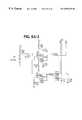
- FIG. 5is a block diagram showing the detectors of FIGS. 1 and 2 coupled through preamplifiers, amplifiers, discriminators, accumulators, and an RS-485 line driver that make up one embodiment of the 16-channel processing units of FIG. 4;
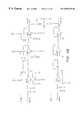
- FIGS. 6A, 6 B, 6 C, 6 D, 6 E and 6 Fare schematic diagrams showing one variation of an analog portion the 16-channel processing units of FIG. 4;
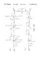
- FIGS. 7A and 7Bare schematic diagrams showing one variation of a digital portion of the 16-channel processing units of FIG. 4;
- FIG. 8is a block diagram of functional components that make up one embodiment of a software system with which the computer of FIGS. 1 and 2 is controlled;
- FIG. 9is a flow chart showing the steps traversed by the computer of FIGS. 1 and 2 in response to the software system of FIG. 7 when an image generation program is executed;
- FIG. 10is a diagram illustrating a preferred screen layout for the image displayed on the display device of FIGS. 1 and, 2 .
- APPENDIX Ais a source code listing of a firmware operating system including steps traversed by each 16-channel processing unit of FIG. 4 in order to quickly relay the photon count information received from the detectors to the computer.
- FIG. 1a schematic diagram is shown of a system made in accordance with one embodiment of the present invention and of a fast-moving target object 10 (“target object”, or “tanker truck”, “truck”, or “railroad car”) containing contraband, wherein discrete photon counting is used with one of several possible velocity-measuring means, a cross-correlation velocity measuring means, to measure density;
- target objector “tanker truck”, “truck”, or “railroad car”
- discrete photon countingis used with one of several possible velocity-measuring means, a cross-correlation velocity measuring means, to measure density
- FIG. 1Shown in FIG. 1 are the fast-moving target object 10 , concealed contraband 12 , a detector array 14 , a radiation source 18 , electronics (or “computer electronics”) 22 , a graphical display device (display) 24 , a video camera 1010 , a video interface 1020 , and a cross-correlation computer 1015 .
- electronicsor “computer electronics”
- displaygraphical display device
- the radiation source 18 and the detector array 14are uniformly able to move with respect to the fast-moving target object 10 .
- the fast-moving target object 10(or truck or railroad car) being inspected can be driven between the detector array 14 and the radiation source 18 at highway speeds of up to about 60 miles per hour or more.
- the detector array 14 and the radiation source 18are both stationarily mounted.
- the detector array 14employs a plurality of “oversized” high efficiency gamma-ray detectors 26 , e.g., up to three hundred and thirty-six (336), detectors arranged in a vertical column.
- the detectors 26make it possible to scan the fast-moving target object (tanker truck or railroad car) 10 with a very low intensity gamma-ray field.
- the oversized detectors 26are used, such as are available as Part No. 1.5M1.5M1.5, NaI (Tl) (sodium iodide crystal, thallium activated) (with R2060 photomultiplier tube) from BICRON of Ohio.
- Such gamma-ray detectorsare scintillation counter-type detectors and are 1.5′′ in diameter, 2.5′′ high, and mounted on a 1.5′′ photo-multiplier tube (PMT).
- an analogous detector of around 0.5 to 1.5′′ in diametermay be used to obtain a finer grid unit mapping of 0.4 to 1.0 inches along one or more dimensions of the fast-moving target object 10 .
- detectors having a pitch Pi.e., space from one detector center to a next closest detector center
- Pspace from one detector center to a next closest detector center
- a pitch P of smaller than twice a radius of the detectors 26is achieved by staggering detectors vertically such that their circular surfaces lie in a single plane, thereby avoiding any shadowing of detectors by other detectors, and then compensating for the staggering by computer computations as described in detail later herein.
- the very low intensity gamma-ray field useable with gamma-ray detectors 26is low enough in intensity to allow operating personnel to work within it, when a fast-opening shutter (“shutter”; not shown) of the radiation source 18 is closed.
- shutteris opened only when an image is being generated, preferably after all personnel leave an area swept out by a fan beam of the radiation source 18 .
- the very low intensity gamma-ray fieldmay use 662 keV gamma-ray energy from a Cs-137 radiation source.
- 662 KeV gamma-ray energycan be used, however, when the vehicle under inspection is traveling at high-speeds e.g., railroad freight car or highway speeds, and when the shutter is opened, e.g., after a truck driver or train engineer has passed.
- the embodiments of the invention described hereinexpose the cargo to only about 5 microroentgen of gamma radiation or about 15 minutes worth of natural background radiation.
- the radiation source 18is, in one 15 configuration, a 1, 1.6 or 2.0 Curie shuttered mono-energetic source of Cs-137 gamma-rays (662 keV gamma-ray energy).
- a nearly mono-energetic Co-60 sourcemay be used which emits photons at 2 energy levels, in particular, 1170 and 1339 keV.
- a mono-energetic or near mono-energetic sourceis preferable, however, because energy-level filtering of the “softer component” (as in X-rays) can be eliminated.
- a suitable sourceis readily available as Model No. SH-F2 from Ohmart Corporation of Ohio.
- the radiation sourceis used in combination with a collimator that provides a 45° vertical opening (measured from horizontal upwards) and a 10° lateral opening.
- the fast-opening shutteris electrically actuated.
- the radiation source 18provides gamma-rays that are of high enough energy levels (e.g., 662 KeV) to be penetrating of steel walls and only moderately attenuated by steel walls typically found in tanker trucks or railroad cars. Yet such rays are sufficiently attenuated by contraband packages to make them easily detectable by measuring the penetration of the gamma-rays emitted from the source and deriving relative material densities therefrom. In addition, there is negligible backscattering of the gamma-ray energy from the tanker walls, and, in any case, much less than would occur if a high-powered x-ray source was utilized.
- high enough energy levelse.g., 662 KeV
- a highly filtered x-ray sourcecould, in other embodiments, be employed for high-speed inspection applications or for inspection of unmanned vehicles, such a highly filtered source, adds costs and complexity to the system, and detracts from reliability. For these reasons, it is not preferred.
- a velocity measuring system using a cross-correlation methodemploys the video camera 1010 coupled to the cross-correlation computer 1015 through the video interface 1020 , to measure a velocity v of the fast-moving target object 10 at the cross-correlation computer 1015 , using photographic images taken at times T 1 and T 2 , by the video camera 1010 .
- the cross-correlation computer 1015sends velocity information to the electronics 22 (including a computer).
- the video camera 1010located a distance D from the fast-moving target object 10 (e.g., a tanker truck), takes a first photographic image (a “frame” or “first image”) at T 1 ; it then takes a second photographic image (“second image”) at T 2 .
- Times T 1 and T 2correspond to a difference in time ⁇ T.
- the fast-moving target object 10moves a distance ⁇ d in the time ⁇ T.
- the Computer 1015calculates a ratio ( ⁇ ⁇ ⁇ d ) ( ⁇ ⁇ ⁇ T )
- va velocity, of the fast-moving target object 10 and utilizes the varying value of v to determine a count time per grid unit (or “mapped pixel unit” or “mapped pixel size”) at time T 1 through T 2 to produce an undistorted image (i.e., where a square is not imaged as a shortened or lengthened rectangle).
- the second image at T 2is moved until it overlaps with the first image at T 1 .
- the distance moved, ⁇ d, to obtain a best overlapis rapidly calculated by performing a Fast Fourier analysis on each of the first and the second image in digital format before and after achieving a best overlap.
- a resulting cross-correlation functionyields the distance ⁇ d the fast-moving target object 10 moved between time T 1 and T 2
- the values of ⁇ d and ⁇ tthen determine the velocity, v, of the fast-moving target object 10 during a time span between T 1 and T 2 .
- the velocity, vis effectively an average velocity during the time span.
- a count time (also “count” or “sample time”) T c at each of the detectors 26is selected as a function of a fixed distance ⁇ x of travel of the fast-moving target object 10 , and of the measured velocity, v, of the fast-moving target object 10 .
- a distortion-free imageis generated with pixels (not shown) on the display 24 , representing an area of ⁇ x by ⁇ y within the fast-moving target object 10 in real time, line by vertical line, as the fast-moving target object 10 passes between the detector array 14 and the radiation source 18 . While the fast-moving target object 10 is in motion, the velocity of the fast-moving target object 10 is either assumed to be constant, or is measured continuously, in which case the count time T c varies as frequently as each vertical line of pixels.
- the velocity at each instantis read into the image-generating computer 36 to adjust the count time T c to the fixed distance ⁇ x, corresponding to the horizontal measure of each horizontal grid unit, (“picture element”, or “mapped pixel”) during each sample time T c .
- ⁇ xis set equal to ⁇ y
- ⁇ yis proportional to a spacing between neighboring detectors 26
- a radiographic-like image in real time, vertical line by vertical line, during relative motion between the fast-moving target object 10 , the source 18 and the detector array 14is achieved without distortion, despite variations in the velocity and acceleration of the fast-moving target object 10 as it passes between the detector array 14 and the radiation source 18 .
- This imageis generated in real-time at high velocities by fast data-processing circuitry 30 ; drivers 32 and interface 34 .
- a count rate (or “count”) per detector 26is measured representative of a number of photons passing through the grid unit hitting the detector 26 wherein the count rate is high enough to achieve a statistically accurate measure of a contents or density being sampled in a given grid unit ( ⁇ x by ⁇ y), as the fast-moving target object 10 moves a distance ⁇ x at high-speed.
- the count rateis further achieved by a fast analog pulse amplifier 42 , (described later herein) electrically coupled to a photomultiplier-tube type of detector 26 with NaI scintillator, that can operate at a rate of up to two (2) million counts per second.
- a high-speed discriminator 44(described later herein) also operational at the count rate, biased above electronic noise, generates a pulse for each gamma ray detected. The pulses are then counted in an accumulator circuit, 47 , accessed each count time T c , (wherein T c equals ⁇ x/v).
- the fixed distance ⁇ xis 1.76 inches.
- T csample time
- the vertical “linear array” configuration of the detectors 26is made to provide a resolution of grid points spaced about every 1.76 inches along the length of the target vehicle, and about 1.76 inches, on average, along the height of the target vehicle (as projected on the target vehicle vertical lengthwise center plane) when the vehicle is close to a detector tower.
- This resolutionis adequate to achieve a detectability limit of as little as about one pound of contraband per 1.76 inches by 1.76 inches gridpoint (or mapped pixel unit).
- vertical grid unit or vertical scanning length along the target object(“vertical grid unit” or “vertical resolution”) ⁇ y is equal to ⁇ Z D ⁇ P ;
- Zthe distance from the radiation source 18 to a center of the fast-moving target object 10
- Ddistance from the detector array 14 to the radiation source 18
- Spacing between the detectors in the detector arraycan be varied, or for example, counts from adjacent pairs of detectors in the detector array can be combined, to change the mapped pixel size ⁇ y in the vertical direction.
- a smaller grid unit of 0.4 inches or lessmay be scanned to a pixel by using a pitch, P, of 0.4 to 1.0 inches while holding the value of Z D
- FIG. 1AIn an embodiment illustrated by FIG. 1A, three (3) rows of staggered detectors are employed to achieve a pitch smaller than a diameter of the staggered photon detectors 202 .
- a computercorrects for horizontal displacements of two rows of the three rows of staggered detectors.
- a plurality of staggered photon detectors 202are employed wherein a low level intensity radiation source (e.g. 1.6 Curies) may optionally be employed in accordance herewith.
- the staggered detectors 202may preferably be oversized (e.g. about 1.5′′ diameter and about 2.5′′ long) and have a pitch P smaller than the diameter 2r of the staggered detectors 202 .
- Three (3) vertical rows R of staggered detectors 202are employed, instead of a single row of detectors 26 shown in FIG. 1 .
- the three (3) vertical rows Rare vertically staggered from each other.
- the pitch P between two (2) closest adjacent such staggered detectors 204 , 206may preferably be about 0.7′′, when employing staggered detectors 202 having a 1.5′′ diameter, thereby yielding a count rate of about 20,000 counts/second for each staggered detector 202 .
- the staggered detectors 202are staggered from each other in a vertical direction, yet their circular surfaces all lie in a same plane, thereby avoiding shadowing from any other staggered detector 202 while enabling a smaller pitch P.
- the image-generating programcorrects for horizontal displacement of each of two (2) side rows S of the staggered detectors 202 from a center row C (of the 3 vertical rows R) of staggered detectors 202 in the following manner.
- a center vertical-line imageis first generated for the center vertical row C.
- the vertical resolution, R vert (vertical grid unit) sizeis selected to be around 1.0′′ utilizing staggered detectors 202 with a diameter of 21 ⁇ 4′′
- the count rate of the staggered detectorsmay optionally be about 90,000 photon counts/second with the 1.0′′ vertical resolution, which is high enough to achieve a relatively high speed photon imaging capability for the 1.0′′ vertical resolution. This count rate is adequate for high speed scanning, yielding about 1000 counts per grid unit at 5 miles per hour and 500 counts per grid unit (pixel) at 10 miles per hour scanning speed.
- a scanning speedis proportional to a square of a grid unit size. For example, if a 1′′ grid unit size is increased to a 2′′ grid unit size, employing the same number of counts/pixel, the scanning speed may be increased by a factor of four (4), since the scanning speed is increased by the square of a ratio of the grid unit sizes (i.e. 2′′/1′′).
- an entire length of the fast-moving target 10is scanned automatically with a fan beam, in a single sweep.
- a fan beamFor example, an entire train of about 100 to 200 freight cars, traveling at up to 10 mph, can be inspected at Laredo, Texas, as the train enters the United States. At these inspection speeds, the “flow of commerce” is not impeded.
- FIG. 2an analogous configuration is used for an alternate arrangement employing a radiation source 18 and a detector array 14 , wherein the radiation source 18 and the detector array 14 are moving synchronously in respect to a stationary target object 10 .
- Shown in FIG. 2are the stationary target object (truck) 10 , concealed contraband 12 , a detector array 14 , a detector array truck or trolley 16 , a radiation source 18 , a radiation source truck or trolley 20 , processing electronics 22 , a graphical display device 24 , and a computer 36 .
- the detector array truck 16 and the radiation source truck 20are designed to travel synchronously along parallel tracks.
- the trucks 16 , 20are mounted on tracks, and employ a synchronous drive motor (not shown) and a variable frequency generator (not shown) for controlling the speed of the synchronous drive motor, such as are available as Model No. SA0100 from Becker Equipment (Mark Becker P. E.) of Vista, Calif. However, numerous known substitutes can be employed therefore.
- the trucks 16 , 20are moved synchronously along parallel paths spanning the entire length of the target object 10 to be inspected.
- This grid unit sizecan easily be selected by one skilled in the art based on the disclosure provided herein and dependent upon an optimum tradeoff between minimum contraband content detectability, throughput (i.e., inspection time per tanker truck), and gamma-ray field-strength (and other safety concerns).
- a truly non-invasive inspection techniqueis provided in which there is no need to manually inspect the vehicle, or, with the fast-opening shutter, to even stop or slow the truck 10 .
- the shutteris closed after the target object 10 (truck or entire train) passes by.
- FIG. 3one embodiment of a system made in accordance with yet another embodiment of the present invention including a velocity-measuring system is shown.
- a similar velocity-measuring systemcould be employed in the system of FIG. 1 in lieu of the system shown in FIG. 1 .
- the magnetic pick off system illustrated in FIG. 3includes a pair of velocity sensors (or wheel transducer units) 310 , spaced a known distance apart to determine the velocity v of the train 300 at each instant after detecting the train's passage. As a wheel 380 of the train 300 passes each of the pair of wheel transducer units 310 , a time is clocked and recorded. A known distance (e.g., inches) and a difference in time is enough to compute the velocity of the train 300 . The measured velocity v is calculated by an Auxiliary Processor Unit, 340 , coupled to a modem 350 . The modem 350 sends a velocity signal through an RS-232 line 360 into a host computer 370 coupled to the RS-232 line 360 .
- Image software contained within the host computer 370is then used to compute a detector sampling period or the count time T c so that a contents of the train 300 corresponding to a fixed grid unit size ⁇ x and ⁇ y defined earlier herein is detected by the detector array 14 and mapped to a pixel in an undistorted fashion. In this fashion, an undistorted image is achieved independent of the velocity v of the train 300 passing between the detector array 14 and the radiation source 18 during each sampling period T c .
- a doppler radar systemsuch as the Rail Falcon, developed for Science Applications International Corporation (SAIC), of San Diego, Calif. by the FALCON Corporation, measures velocities from 0.3 miles per hour to 99 miles per hour with a precision of +0.1 miles per hour. This is an alternative method of measuring the velocity v of the truck or the train 300 being inspected.
- the doppler radar systemis similar to a police-type radar gun used for interdiction of speeders along the highway, except it is specially engineered to yield high precision, and to measure down to the very low-velocity limit of trains crossing the border or trucks accelerating from a stand-still.
- the Rail Falconhas an RS-232 output for reading the velocity signal into the computer 1015 for generating an image.
- a radar range finder(not shown) with high precision and providing many range readings per second, may also be employed in a further variation of the system, such as a mobile vehicle inspection system such as illustrated in FIG. 3 A.
- the velocity-measuring devicemay be a commercially available device that utilizes a pressure pad that is activated when a truck tire passes over the pressure pad. Employing two or more such pressure pads, spaced at a known distance apart, provides a measure of the velocity of the vehicle that can be fed to the processing electronics 22 (FIGS. 1 and 2) as a part of the image generation process.
- the velocity informationis fed into the processing electronics 22 (FIGS. 1 and 2) to determine the sampling period or count time T for the detectors 26 , so as to obtain a fixed horizontal grid unit size, ⁇ x, that matches the vertical grid unit size, ⁇ y determined by the pitch, the vertical spacing between detectors, and the proximity of the train 300 or the fast-moving target 10 to the radiation source.
- the detector array 14(FIGS. 1 and 2) and the radiation source 18 may be fixed or stationary rather than mounted on the radiation source truck (or trolley) 20 and the detector array truck (or trolley) 16 illustrated in FIG. 2 .
- the tanker truck 10 or railroad carcan be driven past the detector array 14 and radiation source 18 with the determination as to the densities within the truck 10 being made automatically by adjusting the time interval of detector readings in order to normalize the horizontal pixel width ⁇ x as the truck 10 or railroad car passes between the radiation source 14 and the detector array 18 .
- the fast-opening shutteradds further protection of an occupant of the fast-moving target object 10 , the train 300 or the truck 10 of FIG. 2 .
- the shutterplaced at the radiation source 18 , in a line-of-sight to the detector array 14 , remains closed when an occupant passes through the line-of-sight.
- the shutterblocks gamma rays from leaving the radiation source 18 , providing heightened safety by not exposing the occupant to the radiation.
- the shutteropens very quickly (e.g., in 250 milliseconds) after an engine passes the radiation source 18 , if the engine is in front of the fast-moving target object 10 , the train 300 or truck 10 .
- the shuttercloses before the engine passes the radiation source 18 , if the engine is in back of the fast-moving target object 10 .
- this shuttercloses by return-spring action in event of an electrical power failure.
- a mobile, uniplatformed, vehicle inspection system (mobile system) 300 ′is shown wherein both a radiation source 18 ′ and a linear detector array 14 ′ are mounted on only one mobile platform, such as a truck, and are deployed using a controllable source boom (source boom) 310 ′ to effect the proper spacing for passage of a fast-moving or stationary target 10 therebetween.
- a radiation source 18 ′ and a linear detector array 14 ′are mounted on only one mobile platform, such as a truck, and are deployed using a controllable source boom (source boom) 310 ′ to effect the proper spacing for passage of a fast-moving or stationary target 10 therebetween.
- the mobile system (“mobile system”) 300 ′comprises a truck 16 ′; the radiation source 18 ′ suspended at the end of the controllable source boom 310 ′ that is coupled to the truck 16 ′; and the linear detector array 14 ′ also coupled to the truck 16 ′.
- the source boom 310 ′is long enough such that when it is deployed, the radiation source 18 ′ and the linear detector array 14 ′, are sufficiently laterally spaced so as to allow for the passage of the fast-moving target 10 therethrough.
- the mobile system 300 ′is optionally used in two possible modes of operation, 1) a stationary-target mode, and 2) a fast-moving (or moving) target mode.
- the radiation source 18 ′such as a 1.6 Ci Cs-137 source, is suspended from a far end of the source boom 310 ′ so as to facilitate imaging of the fast-moving target object 10 in either of the two possible modes.
- the radiation source 18 ′is opened during scanning of the fast-moving target object 10 , and a narrow fan-shaped beam is directed at the linear detector 14 ′.
- the linear detector 14 ′is a 15 ′ high detector array including five (5) three-foot modules.
- Each three-foot modulecomprises three (3) vertical rows of 1.5 inch diameter, 2.5 inch long NaI (TI) detectors, with sixteen ( 16 ) detectors 26 in each vertical row.
- the three (3) rowsare staggered vertically, such as illustrated by FIG. 1A, such that the staggered detectors 202 of 1.5 inch diameter, provide pitch , P, of about 0.72 inches, and vertical resolution about 0.48 inches.
- an image-generating computersuch as the host computer 370 generates an image in the manner such as described for the detector configuration illustrated in FIG. 1 A.
- the truck 16 ′scans the target object 10 while the target object is stationary and without an occupant, while the truck 16 ′ moves along a length of the fast-moving target object 10 to produce a full image of its contents.
- the truck 16 ′need not move at exactly the same speed during the entire scan because the time constant T c between which detector readings (photon counts) are recorded is varied as a function of the velocity of the truck (which is monitored by the image-generating computer, which receives a velocity signal from speedometer equipment aboard the truck), in order to maintain a substantially constant horizontal pixel width ⁇ x.
- the truck 16 ′is stationary and the occupant of the target object 10 drives the target object 10 just past a source fan beam region 320 ′ to avoid the radiation.
- the shutter(not shown), such as described earlier, is then opened and the occupant drives the fast moving target object 10 at about a nominal rate of acceleration which has been clocked at about 33 inches/sec 2 .
- a velocity measuring system(such as one of the velocity-measuring systems described hereinabove), such as shown and described in reference to FIG. 1, or such as a high repetition conventional radar range as mentioned earlier herein, is aimed at the target object 10 and measures position data thereof several times per second.
- the position datais sent to an image-generating computer (not shown), such as the host computer 370 shown in FIG. 3 .
- the position data, together with time data,is next converted into velocity data by the image-generating computer (not shown) to form a velocity profile v(t).
- the proportionality of ⁇ y to pitch Phas been previously described herein.
- the moving target mode of operationrequires as little as about 6 seconds to fully image the fast-moving target object 10 for an accelerating vehicle.
- the fast-moving target object 10can be inspected at about 5 miles/hour or greater, while the mobile system 300 ′ maintains the horizontal and the vertical resolution (grid unit) for imaging of about 0.5 inches, in accordance herewith.
- any of the above-cited velocity measuring systemsenables the mobile system 300 ′ to scan and image at a variety of variable speeds and accelerations while still maintaining excellent imaging resolution, and distortion-free images, at ultra high speeds (relative to heretofore known imaging approaches) such as up to about 60 miles per hour.
- a velocity of the target object 10 or a mobile systemcan be selected and adapted according to the mission at hand.
- a color or grey-scale tone definition per pixelor the number of colors which that pixel can have, effectively decreases accordingly.
- This decrease in color definition per pixeloccurs because as the target velocity increases, a number of photons reaching the detector 26 in the detector array 14 decreases, since a count time T c is decreased, as it takes less time for a target length corresponding to one pixel to pass the detector 26 . Since there are less overall photons to count, (a smaller number of counts/pixel), the counts can be distributed among fewer colors or grey-scale tones than if there were a higher count rate.
- a higher target or mobile system velocitymay be selected, sacrificing some color definition as described above. Otherwise, if a higher color definition image is required, such as for disarming an explosive device, a lower target or mobile system velocity may be selected.
- FIG. 4a block diagram is shown of the systems of FIGS. 1 and 2 showing gamma/x-ray detectors coupled through 16-channel processing units, accumulators, RS-485 line drivers, and an RS-485 interface card to a computer, wherein the computer processes discrete photon count information received from the detectors 26 and causes a display device to display an image of the contents of a target object 10 , such as the tanker truck of FIG. 1, or FIG. 2 in response thereto.
- a target object 10such as the tanker truck of FIG. 1, or FIG. 2 in response thereto.
- the detector array 14is depicted in FIGS. 1 and 2, as are the electronics 22 and the graphical display device 24 .
- the detector array 14employs the plurality of gamma/x-ray detectors 26 .
- the gamma/x-ray detectors 26are coupled in groups of 16 gamma/x-ray detectors each to accumulators, which are in-turn coupled to 16-channel data processing circuits 30 .
- the number of gamma/x-ray detectors 26 useddepends on the height of the vehicles to be inspected and the desired resolution, i.e., number of pixels, in the image desired.
- 48 gamma/x-ray detectorsare employed in a linear vertical fashion and a grid unit size or resolution of about 2.5 inches is selected.
- the detector array 14comprises 64 detectors 26 with a pitch of 1.76′′, the detectors 26 being sampled at 600 times per second (sampling every 1.7 msec per detector) corresponding to a speed of 60 mph of the fast-moving target object 10 .
- VACIS-IIthree (3) vertical rows of 112 detectors 26 each, (336 detectors 26 ) are employed and a vertical and horizontal resolution of about 0.4 inches is selected (or 0.42 inches).
- the 16-channel data processing circuits 30each include an accumulator 47 , the 16-channel data processing circuits 30 being coupled to an RS-485 line driver/firmware (“driver/firmware”) 32 , which is coupled to an RS-485 interface (or RS-485 card) 34 .
- the RS-485 interface 34is embodied on a circuit card located within a computer system 36 .
- a suitable RS-485 interfaceis available as Model No. 516-485, Part No. 3054 from Sea Level Systems, Inc., and from numerous other vendors under respective model/part number designations.
- the computer system 36which is preferably a Pentium- 300 based personal computer system, or a faster (newer) computer system, operates programmatically under the control of a software system.
- the computer system 36receives data on velocity from a velocity measuring device 35 , such as any of the devices described herein (see FIG. 1, FIG. 3 ), and uses the velocity data to adjust the count time ⁇ c as previously defined herein (as a sample period for the detectors 26 ).
- the computer system 36also receives information on an accumulated photon count from the accumulator 47 through the driver/firmware 32 (described later) originating initially from detector pulses from each of the 16-channel data processors 30 , in response to the detection of individual photons by the gamma/x-ray detectors 26 , 202 (FIGS. 1, 1 A and 2 ).
- the software systemaccepts a value of the accumulated photons counts passed to it by a discriminator 44 , which ensures each pulse height, from energy deposited in the detector by the photons, is above an electronic noise level.
- the accumulated photon countspermits for a noiseless signal, as compared to measuring current from many more photons which has associated current noise, because each photon is counted above a noise threshold.
- the software systemgenerates a radiographic image-like display output signal in response to the accumulated counts.
- the radiographic, image-like display output signal generated by the composite softwareis coupled to the graphical display device 38 , which is preferably a Super-VGA monitor, and is used by the graphical display device 38 to generate a graphical representation of the densities within the vehicle under inspection.
- the present embodimentUnlike some prior art systems, which do not generate a graphical representation, i.e., a “picture”, of the densities of the contents of the vehicle under inspection, the present embodiment generates such a picture.
- each vertical line composing this pictureis generated sequentially in real time, while the fast-moving target changes position relative to the source 18 and to the detector array 14 .
- thisallows for easy, instantaneous, direct visual interpretation of the results of the scanning of the vehicle under inspection, making possible prompt interdiction of the vehicle before unloading the contraband, as opposed to interpreting more subtle indications of the densities within the vehicle under inspection as may be required in prior art systems.
- the preferred software systemalso causes the display of a reference image simultaneous with the image generated in response to the vehicle under inspection, so that an operator of the present embodiment can easily make a visual comparison between what a vehicle of the type being inspected should “look like”, and what the vehicle under inspection actually “looks like”. Such “side-by-side” inspection further simplifies the detection of contraband using the present embodiment.
- photon penetrationas opposed to backscatter
- photon penetrationcan be used to generate a side, as opposed to a bottom/top, image of the vehicle under inspection, because a radiation exclusion zone is small for a low-intensity field.
- Thisrepresents a significant improvement over prior art systems wherein a bottom/top presentation of the radiation source is required to avoid the need for excessive radiation shielding, but dictates that the vehicle's frame, drive train, wheels, etc., interfere with the density measurements taken based on radiation penetration.
- Backscatter-type density measurement systemsare less accurate due to the non-uniform backscattered radiation on which they rely for density measurement.
- back-scattered photonshave significantly decreased energy, and are less penetrating and cannot effectively measure high pressure tanker trucks with double-walled thick steel walls.
- FIG. 5a block diagram is shown of the detectors of FIG. 4 coupled through preamplifiers 40 , amplifiers 42 , threshold discriminators (discriminators) 44 , accumulators 47 , and an RS-485 line driver/firmware 32 , that make up one embodiment of the 16-channel processing units of FIG. 4 .
- the RS-485 driver/firmware 32comprises microprocessor firmware 31 , a communications controller 33 and a line driver 39 .
- Each of the radiation detectors 26is coupled to a preamplifier 40 within the 16-channel data processing unit 30 .
- Each preamplifier 40is coupled to an amplifier 42 , which is in turn coupled to a discriminator 44 .
- Each discriminator 44generates an electrical pulse for each photon detected above an electronic noise level by the radiation detector 26 coupled thereto.
- the use of (non-integrating) discrete photon counting at the levels of photon fluxes employed herewith (i.e. relatively very low radiation intensity) together with the use of the discriminator 44 to allow photons (or pulses) to be counted only above a cut-off threshold energyallows for a much improved, virtually noiseless system, using a lower strength sources than conventionally used.
- every pulse generated from the discriminator 44represents an actual photon from the radiation source 18 , 18 ′; that is, only photons generated from the radiation source 18 , 18 ′ are counted at the accumulators 47 . Since each pulse counted at the accumulator 47 represents an actual photon from the radiation source 18 , 18 ′, a photon-by-photon count (or count rate) at the accumulator 47 represents a virtually noiseless signal of how many photons from the radiation source 18 , 18 ′ hit each detector 26 .
- This photon-by-photon virtually noiseless signalhas several advantages over some prior arts systems wherein photon-integration over a myriad of photon energy levels is employed. Even with such prior art, or state of the art integrating discrete photon counting systems (such as may be used with standard X-ray detectors) it is necessary to bombard the detector 26 with many more orders of magnitudes of photons in order to drown out a substantial noise contribution (e.g., leakage current) of a signal.
- a substantial noise contributione.g., leakage current
- a common method of integrating a detector countis to generate a current from charge collected as a result of energy being deposited in a crystal of the detector 26 , rather than to count the pulses generated for each photon deposited in the detector 26 .
- the strength of the currentis then measured, in the conventional systems, instead of the total number of photon counts in accordance with the present invention. From this current must be subtracted a varying (temperature dependent) background current.
- Another further problem with this form of integrationis that there is always some parametric leakage current involved in a circuit or a solid state device measuring the current, and this further contributes to the noise of the signal, worsening the initial problem.
- a mono-energetic sourcesuch as a 662 keV ⁇ -ray source of Cs-137 or a near mono-energetic source such as Co-60 (dual energy, one energy level at 1170 keV and another at 1330 keV) is employed to make discrete photon counting at the threshold cut-off energy level or narrowband much easier, since the radiation source 18 is constant with time and need not be filtered to filter out a soft, lower energy component.
- any sourcecould be used in conjunction with a filter placed around the radiation-source 18 , 18 ′, filtering out photons of energies outside a desired energy level.
- pulse pileupis generally not of significant concern.
- Count rates of up to 90,000 counts/secondsare presently being counted with negligible “chance coincidence” loss with pulse amplifiers capable of counting nearly two million counts/seconds (via 40 nanosecond amplifier “pulse” time constants).
- the discriminators 44 within each of the 16-channel data processing units 30are coupled through the accumulator 47 to a line driver/firmware (RS-485 driver/firmware) 32 which includes a microprocessor firmware (processor) 31 coupled at an output to a communications controller 33 coupled at an output to a line driver 39 .
- a line driver/firmware 32which includes a microprocessor firmware (processor) 31 coupled at an output to a communications controller 33 coupled at an output to a line driver 39 .
- processormicroprocessor firmware
- Each of the 16-channel data processing units 30includes its own line driver/firmware 32 .
- the line drivers/firmware (RS-485 primer/firmware) 32operate under the programmatic control of a firmware operating system in the processor 31 which processor 31 also controls the communications controller 33 and the line driver 39 , such as shown in APPENDIX A.
- the preamplifiers 40 , and amplifiers 42function in a conventional manner to amplify signals generated by the detectors 26 connected thereto.
- Outputs of the amplifiers 42are passed along to the discriminators 44 , which accept pulses that are well above a noise threshold (e.g, about twice the noise threshold).
- the pulsesare passed by the discriminator 44 and then counted in an accumulator 47 for each detector 26 , resulting in accumulated counted pulses (accumulated pulse counts), thereby generating a count rate as previously discussed.
- the line driver/firmware 32passes the accumulated pulse counts, which pulses are accepted past a threshold by each of the discriminators 44 and passed to each accumulator 47 , within a particular 16-channel data processing unit 30 , along to the computer via the RS-485 interface 34 illustrated in FIG. 4 .
- FIGS. 6A, 6 B, 6 C, 6 D, 6 E and 6 Fschematic diagrams are shown of one variation of an analog portion the 16-channel processing units of FIGS. 4 and 5.
- the schematics of FIGS. 6A, 6 B, 6 C, 6 D, 6 E and 6 Fare self-explanatory to one of skill in the art of circuits and therefore further explanation of these figures is not made herein.
- FIGS. 7A and 7Bschematic diagrams are shown of one variation of a digital portion of the 16-channel processing units of FIGS. 5 and 6.
- the schematics of FIGS. 7A and 7Bare self-explanatory to one of skill in the art and therefore further explanation of these figures is not made herein.
- FIG. 8a block diagram is shown of functional components that make up one embodiment of a software system with which the host computer 370 of FIG. 4 is controlled.
- Block 100Upon initialization (Block 100 ), the computer, under control of the software system, initializes (Block 102 ), and loads a default color map display (Block 104 ), which maps detected densities within the vehicle under inspection, i.e., pulse counts, to specific colors to be produced on the display device 38 (shown in FIG. 4 ). Next, the user is presented with a main menu (Block 106 ), and the computer is instructed to wait until an operator instructs the software system as to what step to take next.
- a default color map displayBlock 104
- the help functiondisplays tutorial and/or reference information to the operator via the display device, as is common in the computing arts.
- the “Display Image from Disk in Upper Window” option(Block 110 ).
- this optionallows the operator to load a saved display image from a hard or floppy disk drive within the computer, and to automatically display the image in the upper display window on the display drive.
- the upper display windowin accordance with the present embodiment, is used to display a reference image, i.e., an image of the same make of truck under inspection, but while empty, i.e., containing no contraband.
- a further option that can be selected by the operatoris a “Display Image from Disk in Lower Window” option (Block 112 ).
- this optionallows the operator to load a saved image from a hard or floppy disk drive within the computer, and automatically displays the image in the lower display window on the display drive.
- the lower display windowin accordance with the present embodiment, is used to display an inspection image, i.e., an image of the vehicle under inspection.
- a useful function of this optionis for reinspection of a vehicle at a later time by a supervisor in order to maintain quality control. Because the image is stored on disk, it is not necessary that the vehicle be present when this re-inspection takes place. The saved image of the vehicle, after being loaded, can easily be visually compared with the reference image loaded into the upper display window.
- the next option available to the operatoris the “Save Image from Lower Window to Disk” option.
- This optioncan be used to save an image of a vehicle under inspection for later reinspection, or can be used to save a reference image after a known empty vehicle has been inspected, i.e., scanned using the present embodiment.
- Block 116the operator is able to load a previously saved color lookup table from disk. This allows the user to retrieve a color map, different from the default color map, so that a different set of colors can be mapped to various density measurements, i.e., pulse counts within the vehicle.
- the next optionis the “Acquire Image from Counters and Display to Screen” option (Block 118 ).
- This optioninitiates an image generation program, as described below in reference to FIG. 9, which causes the detector array 14 and the radiation source 18 to perform density measurements and causes the display of an image indicative of the various densities within the vehicle under inspection in the lower display window on the screen display.
- the present embodimentallows the operator to display a reference image in the upper display window while the inspection is being conducted, so that he or she can visually compare what the vehicle under inspection should look like empty with what the vehicle under inspection in fact looks like. In this way, the operator is able to determine whether or not the vehicle under inspection may contain contraband.
- Blocks 120 and 122allow the operator to set values for what is referred to herein as the “K” constraint and the “L” constraint. These two “constraints” function in a manner similar to the well known functioning of the brightness and contrast controls on commonly available cathode ray tube-type displays. These values affect the mapping of colors to the various pulse counts, which is performed as follows:
- a “white” leveli.e., a number of counts corresponding to zero density, is determined for each sensor during detector calibration, which is a step in image acquisition as described below in reference to FIG. 7;
- variable “T”is then set equal to this white level times the reciprocal of the number of photons counted by a particular detector at a particular horizontal position on the vehicle;
- Tis set equal to one
- Dis set to 1 or 254, respectively.
- Redisplay optionssuch as these are useful to the operator if the images displayed on the display device 38 become corrupted in some way, as for example may occur if text is sent to the display device 38 while it is displaying a graphical image.
- the usermay also “Reset a Default Color Map Array” (Block 130 ), “Load a Next Color Map Array” (Block 132 ) and “Load a Previous Color Map Array” (Block 134 ). These options are used to step through various preconfigured color maps, and to reestablish the default color map, so that the operator can utilize a color map that best emphasizes the features of the vehicle under inspection that he or she is inspecting.
- a final operator-selectable option depicted in FIG. 8is an “End” option (Block 146 ). This option is used by the operator to exit the software system and to return control to an operating system, such as is known in the art of computer technology.
- FIG. 9a flow chart is shown of the steps traversed by the computer 36 of FIG. 4 in response to the software system of FIG. 8 when an image generation program is executed.
- the image generationis initialized (Block 202 ), and the movement of either 1) the radiation source truck 20 , and the detector array truck 16 , if used, or alternatively, 2) the movement of the mobile system 300 ′ in another embodiment, or 3) the movement of the target object 10 , is initiated (Block 204 ).
- the detectors 26are calibrated (Block 206 ) by irradiating the detectors with the radiation source 18 at a point along the track before the radiation source 18 , 18 ′ and the detector array 14 , 14 ′ become aligned with the vehicle or the target object 10 , to be inspected, such that a horizontal length of the target object will be traversed upon continuation of the initiated movement, e.g., before the vehicle under inspection is interposed between the detector array 14 , 14 ′, and the radiation source 18 , 18 ′.
- Such irradiation of the detectors 26establishes a baseline of radiation (or “white” photon count level) corresponding to a density in the vehicle being inspected of approximately zero density and corresponding to a maximum photon count. Three photon counts are made in this manner for each detector 26 . Such counts are then arranged for each detector 26 and then stored in an array having a white level element for each detector 26 .
- a horizontal positionis then set to zero (Block 208 ).
- the horizontal positioncorresponds to a position along the track or a mobile system path or a target object path arbitrarily selected to be a first position at which density measurements are taken. Irrespective of which embodiment is employed or which reference is moving (the detector-source, or the vehicle or target object 10 ), this horizontal position should be at a point before the vehicle is interposed between the detector array 14 and the radiation source 18 .
- a detector countis set to zero (Block 210 ), which corresponds to a first of the detectors 26 in the detector array 14 to be queried for a photon count. If the target object 10 is moving, a velocity of the target object 10 is measured by any of the several methods described earlier, herein, and a count time per grid unit is set (Block 211 ) according to the measured variable velocity of the target object to effect a desired mapped grid unit size without distortion. Next, this detector is queried for a photon count and is instructed to restart counting photons (Block 212 ). In response to this instruction, the detector queried restarts counting photons (Block 214 ) and the previously determined number of photon counts is passed along to the computer (Block 216 ).
- This number of photon countsis stored into an array within a memory in the computer (Block 218 ) and is then converted into a pixel value (Block 220 ). Conversion into the pixel value includes mapping the number of photon counts to a color to be displayed on the display device. Such mapping is described more completely above in reference to FIG. 8 .
- the detector number queriedis converted into a vertical position on the screen display (Block 222 ) and the horizontal position of the radiation source 18 , 18 ′ or the mobile system path or the target object path and the detector array 14 , 14 ′ along the tracks is converted to a horizontal position on the screen display.
- the pixel at the determined horizontal and vertical positionsis illuminated using the color corresponding to the number of photon counts, as previously converted (Block 224 ).
- Block 226a determination is made as to whether all of the detectors 26 in the detector array 14 have been queried for a number of photon counts for the current horizontal position (Block 226 ). If all the detectors have not been queried (Block 226 ), the detector number to be queried is incremented (Block 227 ) and execution of the image generation program continues by querying the next detector in the detector array 14 for the number of photon counts, and by instructing such detector to restart counting (Block 212 ). Execution continues from this point as described above (Block 214 et seq.)
- the horizontal positionis incremented (Block 228 ) and a determination is made as to whether or not the target object 10 or the radiation source 18 , 18 ′ and the detector array 14 , 14 ′ are still moving (Block 230 ). If the radiation source 18 , 18 ′ and 35 the detector array 14 , 14 ′ are still moving (Block 230 ), the detector to be queried is reset to zero (Block 210 ) and execution of the image generation program continues as described above (Block 212 et seq.).
- FIG. 10a diagram is shown illustrating a preferred screen layout for the images displayed on the display device of FIG. 4 .
- the screen display 300is divided into an upper display 302 , a lower display 304 and a color bar 306 .
- the upper display 302can be used, as mentioned above, to display images stored on disk. These images will generally be reference images used for visual comparison with an image representative of a vehicle under inspection.
- the lower display 304in addition to being able to display images stored on disk, is used to display images, as they are generated, indicative of the various densities within the vehicle under inspection. Both the upper and lower displays 302 , 304 are color mapped using the current color map, gain and offset, so that they can be visually compared to one another.
- Any differences in a reference image, and an image generated during inspection of a vehiclemay indicate the presence of contraband within the vehicle under inspection.
- the color bar 306indicates the colors that are mapped to the various densities detectable by the present embodiment, serving as a reference to the operator as to which colors indicate higher densities than others. As suggested in FIG. 10, colors nearer to the top of the color bar 306 are indicative of more density, i.e., fewer photons counted as penetrating the vehicle under inspection, and colors nearer to the bottom of the color bar 306 are indicative of less density, i.e., more photons counted as penetrating the vehicle under inspection.
- a system and associated methodsare provided in the present embodiment for determining the densities within a vehicle under inspection based on discrete photon counting, and for generating an image indicative of such densities.
- determinationis made based on discrete photon counting, thereby eliminating the need for high levels of gamma-ray or x-ray radiation.
- the present embodimentthus, eliminates the need to stop and manually inspect vehicles at border crossings, and other inspection points.
- the present embodimentbecause of the very low levels or gamma-ray or x-ray radiation, advantageously eliminates the need to stop and evacuate the vehicle before it is subjected to very high strength gamma-ray or x-ray radiation, when the radiation source shutter opens just after the driver has passed:
- the scattered radiation dosage to the driveris very low, and of an acceptably minute level.
- the present embodimentprovides for the determination of densities within the vehicle without the need even to stop the vehicle, such as a train. Slightly higher radiation levels may, in accordance with this variation, be used to reduce or even eliminate the slowing needed to determine the densities within a vehicle, and to generate an image indicative thereof, if the radiation source is closed when the driver is “in the beam.”
Landscapes
- Physics & Mathematics (AREA)
- General Physics & Mathematics (AREA)
- Life Sciences & Earth Sciences (AREA)
- General Health & Medical Sciences (AREA)
- Analytical Chemistry (AREA)
- Biochemistry (AREA)
- Chemical & Material Sciences (AREA)
- Health & Medical Sciences (AREA)
- Immunology (AREA)
- Pathology (AREA)
- High Energy & Nuclear Physics (AREA)
- General Life Sciences & Earth Sciences (AREA)
- Geophysics (AREA)
- Analysing Materials By The Use Of Radiation (AREA)
Abstract
Description


Claims (67)
Priority Applications (7)
| Application Number | Priority Date | Filing Date | Title |
|---|---|---|---|
| US09/398,547US6507025B1 (en) | 1995-10-23 | 1999-09-17 | Density detection using real time discrete photon counting for fast moving targets |
| US09/925,009US7045787B1 (en) | 1995-10-23 | 2001-08-09 | Density detection using real time discrete photon counting for fast moving targets |
| US10/833,131US7408160B2 (en) | 1995-10-23 | 2004-04-28 | Density detection using real time discrete photon counting for fast moving targets |
| US11/292,065US7365332B2 (en) | 1995-10-23 | 2005-12-02 | Density detection using real time discrete photon counting for fast moving targets |
| US11/292,093US7368717B2 (en) | 1995-10-23 | 2005-12-02 | Density detection using real time discrete photon counting for fast moving targets |
| US11/445,112US7335887B1 (en) | 1995-10-23 | 2006-06-02 | System and method for target inspection using discrete photon counting and neutron detection |
| US11/445,442US7388205B1 (en) | 1995-10-23 | 2006-06-02 | System and method for target inspection using discrete photon counting and neutron detection |
Applications Claiming Priority (3)
| Application Number | Priority Date | Filing Date | Title |
|---|---|---|---|
| US54699995A | 1995-10-23 | 1995-10-23 | |
| US92185497A | 1997-09-02 | 1997-09-02 | |
| US09/398,547US6507025B1 (en) | 1995-10-23 | 1999-09-17 | Density detection using real time discrete photon counting for fast moving targets |
Related Parent Applications (1)
| Application Number | Title | Priority Date | Filing Date |
|---|---|---|---|
| US92185497AContinuation-In-Part | 1995-10-23 | 1997-09-02 |
Related Child Applications (1)
| Application Number | Title | Priority Date | Filing Date |
|---|---|---|---|
| US09/925,009Continuation-In-PartUS7045787B1 (en) | 1995-10-23 | 2001-08-09 | Density detection using real time discrete photon counting for fast moving targets |
Publications (1)
| Publication Number | Publication Date |
|---|---|
| US6507025B1true US6507025B1 (en) | 2003-01-14 |
Family
ID=27068432
Family Applications (1)
| Application Number | Title | Priority Date | Filing Date |
|---|---|---|---|
| US09/398,547Expired - LifetimeUS6507025B1 (en) | 1995-10-23 | 1999-09-17 | Density detection using real time discrete photon counting for fast moving targets |
Country Status (1)
| Country | Link |
|---|---|
| US (1) | US6507025B1 (en) |
Cited By (104)
| Publication number | Priority date | Publication date | Assignee | Title |
|---|---|---|---|---|
| US20010048446A1 (en)* | 2000-05-24 | 2001-12-06 | Akira Ishida | Rendering device |
| US20030112920A1 (en)* | 2000-05-11 | 2003-06-19 | Imperial Chemical Industries Plc | Density measurement method and apparatus therefor |
| US20040134986A1 (en)* | 2001-05-08 | 2004-07-15 | Wolfgang Studer | X-ray system comprising an x-ray source, a detector assembly, and an aperture |
| US20040179647A1 (en)* | 2001-09-03 | 2004-09-16 | Jinggi Zhao | Contain inspection system using cobalt-60 gamma-ray source and cesium iodide or cadmium tungstate array detector |
| US20040184136A1 (en)* | 2003-01-16 | 2004-09-23 | Tatsuhito Goden | Driving method of electrophoretic display |
| US20040251415A1 (en)* | 1995-10-23 | 2004-12-16 | Verbinski Victor V. | Density detection using real time discrete photon counting for fast moving targets |
| US20050105665A1 (en)* | 2000-03-28 | 2005-05-19 | Lee Grodzins | Detection of neutrons and sources of radioactive material |
| US20050157842A1 (en)* | 2002-07-23 | 2005-07-21 | Neeraj Agrawal | Single boom cargo scanning system |
| US20050157844A1 (en)* | 2004-01-15 | 2005-07-21 | Bernardi Richard T. | Traveling X-ray inspection system with collimators |
| US20050169421A1 (en)* | 2004-01-30 | 2005-08-04 | Muenchau Ernest E. | Method and system for automatically scanning and imaging the contents of a moving target |
| US20050274917A1 (en)* | 2004-06-09 | 2005-12-15 | Akira Ishisaka | Radiation image reading system |
| US20060056584A1 (en)* | 2002-07-23 | 2006-03-16 | Bryan Allman | Self-contained mobile inspection system and method |
| WO2006036076A1 (en)* | 2004-09-30 | 2006-04-06 | S.C. Mb Telecom Ltd.-S.R.L. | Nonintrusive radiographic inspection method and system for vehicles using two autonimous but synchronously movable mobile units, one carring the source and the other the detector |
| WO2006119605A1 (en)* | 2005-05-11 | 2006-11-16 | Optosecurity Inc. | Method and system for screening cargo containers |
| US20060257005A1 (en)* | 2005-05-11 | 2006-11-16 | Optosecurity Inc. | Method and system for screening cargo containers |
| US20060266948A1 (en)* | 2005-05-24 | 2006-11-30 | Hofstetter Kenneth J | Portable nuclear material detector and process |
| US7166844B1 (en) | 2004-06-01 | 2007-01-23 | Science Applications International Corporation | Target density imaging using discrete photon counting to produce high-resolution radiographic images |
| US20070041613A1 (en)* | 2005-05-11 | 2007-02-22 | Luc Perron | Database of target objects suitable for use in screening receptacles or people and method and apparatus for generating same |
| US20070217572A1 (en)* | 2002-07-23 | 2007-09-20 | Andreas Kotowski | Single boom cargo scanning system |
| US20070237294A1 (en)* | 2006-04-06 | 2007-10-11 | Hoff Paul W | Method and apparatus for the safe and rapid detection of nuclear devices within containers |
| US20070269007A1 (en)* | 2006-05-05 | 2007-11-22 | Alan Akery | Multiple pass cargo inspection system |
| US20080013083A1 (en)* | 2006-02-09 | 2008-01-17 | Kirk Michael D | Methods and systems for determining a characteristic of a wafer |
| US7352844B1 (en) | 2004-01-30 | 2008-04-01 | Science Applications International Corporation | Method and system for automatically scanning and imaging the contents of a moving target |
| WO2008046260A1 (en)* | 2006-10-13 | 2008-04-24 | Nuctech Company Limited | A system and dodging method for imaging and detecting a moving object |
| US7388205B1 (en) | 1995-10-23 | 2008-06-17 | Science Applications International Corporation | System and method for target inspection using discrete photon counting and neutron detection |
| US20080170660A1 (en)* | 2006-05-11 | 2008-07-17 | Dan Gudmundson | Method and apparatus for providing threat image projection (tip) in a luggage screening system, and luggage screening system implementing same |
| US20080223180A1 (en)* | 2007-03-14 | 2008-09-18 | Ping-Chung Huang | Ratchet mechanism for ratchet tool |
| US7430479B1 (en) | 2004-08-17 | 2008-09-30 | Science Applications International Corporation | System and method for analyzing content data |
| US20080240578A1 (en)* | 2007-03-30 | 2008-10-02 | Dan Gudmundson | User interface for use in security screening providing image enhancement capabilities and apparatus for implementing same |
| US20080253514A1 (en)* | 2005-02-25 | 2008-10-16 | Rapiscan Systems Limited | X-Ray Security Inspection Machine |
| US7453987B1 (en) | 2004-03-04 | 2008-11-18 | Science Applications International Corporation | Method and system for high energy, low radiation power X-ray imaging of the contents of a target |
| US20090010386A1 (en)* | 2003-09-15 | 2009-01-08 | Peschmann Kristian R | Methods and Systems for Rapid Detection of Concealed Objects Using Fluorescence |
| US20090010382A1 (en)* | 2003-04-25 | 2009-01-08 | Edward James Morton | X-Ray Monitoring |
| US20090060135A1 (en)* | 2005-12-16 | 2009-03-05 | Edward James Morton | X-Ray Tomography Inspection Systems |
| US20090086907A1 (en)* | 2007-06-09 | 2009-04-02 | Steven Winn Smith | Automobile Scanning System |
| US20090099808A1 (en)* | 2007-10-11 | 2009-04-16 | Winfield Charles B | Method for Monitoring Fouling in a Cooling Tower |
| US20090116614A1 (en)* | 2002-07-23 | 2009-05-07 | Andreas Kotowski | Cargo Scanning System |
| US7596275B1 (en) | 2004-03-01 | 2009-09-29 | Science Applications International Corporation | Methods and systems for imaging and classifying targets as empty or non-empty |
| US7684538B2 (en) | 2003-04-25 | 2010-03-23 | Rapiscan Systems, Inc. | X-ray scanning system |
| US20100085066A1 (en)* | 2003-09-15 | 2010-04-08 | Peschmann Kristian R | Methods and systems for the rapid detection of concealed objects |
| US20100118645A1 (en)* | 2008-11-08 | 2010-05-13 | Kenneth Welker | Coil shooting mode |
| US20100189226A1 (en)* | 2002-07-23 | 2010-07-29 | Andreas Kotowski | Rotatable boom cargo scanning system |
| US20100303287A1 (en)* | 2003-04-25 | 2010-12-02 | Edward James Morton | X-Ray Tomographic Inspection Systems for the Identification of Specific Target Items |
| US20100303329A1 (en)* | 2003-04-25 | 2010-12-02 | Edward James Morton | Imaging, Data Acquisition, Data Transmission, and Data Distribution Methods and Systems for High Data Rate Tomographic X-Ray Scanners |
| US20110004002A1 (en)* | 2008-02-29 | 2011-01-06 | Basf Se | Process for preparing alkyl 2-alkoxymethylene-4,4-difluoro-3-oxobutyrates |
| US20110019797A1 (en)* | 2003-04-25 | 2011-01-27 | Edward James Morton | X-Ray Tomographic Inspection System for the Identification of Specific Target Items |
| US20110026674A1 (en)* | 2009-07-30 | 2011-02-03 | American Science And Engineering, Inc. | Walk-Through Shoe Inspection System |
| US20110038453A1 (en)* | 2002-07-23 | 2011-02-17 | Edward James Morton | Compact Mobile Cargo Scanning System |
| US20110064192A1 (en)* | 2002-07-23 | 2011-03-17 | Edward James Morton | Four Sided Imaging System and Method for Detection of Contraband |
| US20110098870A1 (en)* | 2008-02-28 | 2011-04-28 | Edward James Morton | Mobile Scanning Systems |
| US20110116599A1 (en)* | 2008-02-28 | 2011-05-19 | Rapiscan Security Products, Inc. | Scanning Systems |
| US20110116600A1 (en)* | 2008-02-28 | 2011-05-19 | Edward James Morton | Scanning Systems |
| US7949101B2 (en) | 2005-12-16 | 2011-05-24 | Rapiscan Systems, Inc. | X-ray scanners and X-ray sources therefor |
| US20110142203A1 (en)* | 2008-05-20 | 2011-06-16 | Edward James Morton | Gantry Scanner Systems |
| US7991242B2 (en) | 2005-05-11 | 2011-08-02 | Optosecurity Inc. | Apparatus, method and system for screening receptacles and persons, having image distortion correction functionality |
| US20110204243A1 (en)* | 2008-06-11 | 2011-08-25 | Joseph Bendahan | Composite Gamma-Neutron Detection System |
| US20120008149A1 (en)* | 2010-07-08 | 2012-01-12 | Val Parker | Velometer, navigational apparatus and methods for direct measurement of object's own velocity |
| US8213570B2 (en) | 2006-02-27 | 2012-07-03 | Rapiscan Systems, Inc. | X-ray security inspection machine |
| US8243876B2 (en) | 2003-04-25 | 2012-08-14 | Rapiscan Systems, Inc. | X-ray scanners |
| US8314394B1 (en) | 2009-11-04 | 2012-11-20 | Science Applications International Corporation | System and method for three-dimensional imaging using scattering from annihilation coincidence photons |
| US8325871B2 (en) | 2000-03-28 | 2012-12-04 | American Science And Engineering, Inc. | Radiation threat detection |
| US20130039462A1 (en)* | 2008-02-28 | 2013-02-14 | Rapican Systems, Inc. | Dual mode x-ray vehicle scanning system |
| US20130277568A1 (en)* | 2012-04-23 | 2013-10-24 | Andrei Yoryevich Sherbakov | Method for research of internal structure and / or contents of an object, obtaining an image of the object, and / or the internal structure, and / or the contents, and a system for executing the method |
| US8824637B2 (en) | 2008-09-13 | 2014-09-02 | Rapiscan Systems, Inc. | X-ray tubes |
| US8831176B2 (en) | 2008-05-20 | 2014-09-09 | Rapiscan Systems, Inc. | High energy X-ray inspection system using a fan-shaped beam and collimated backscatter detectors |
| US8840303B2 (en) | 2008-05-20 | 2014-09-23 | Rapiscan Systems, Inc. | Scanner systems |
| US8859981B1 (en) | 2012-11-08 | 2014-10-14 | Leidos, Inc. | Method for autonomous self-blanking by radiation portal monitors to minimize the interference from pulsed X-rays radiation |
| US20140314201A1 (en)* | 2011-12-30 | 2014-10-23 | Tsinghua University | Methods and apparatuses for measuring effective atomic number of an object |
| US8963094B2 (en) | 2008-06-11 | 2015-02-24 | Rapiscan Systems, Inc. | Composite gamma-neutron detection system |
| US8971485B2 (en) | 2008-02-28 | 2015-03-03 | Rapiscan Systems, Inc. | Drive-through scanning systems |
| US9057679B2 (en) | 2012-02-03 | 2015-06-16 | Rapiscan Systems, Inc. | Combined scatter and transmission multi-view imaging system |
| US9113839B2 (en) | 2003-04-25 | 2015-08-25 | Rapiscon Systems, Inc. | X-ray inspection system and method |
| US9218933B2 (en) | 2011-06-09 | 2015-12-22 | Rapidscan Systems, Inc. | Low-dose radiographic imaging system |
| US9223050B2 (en) | 2005-04-15 | 2015-12-29 | Rapiscan Systems, Inc. | X-ray imaging system having improved mobility |
| US9223052B2 (en) | 2008-02-28 | 2015-12-29 | Rapiscan Systems, Inc. | Scanning systems |
| US9285498B2 (en) | 2003-06-20 | 2016-03-15 | Rapiscan Systems, Inc. | Relocatable X-ray imaging system and method for inspecting commercial vehicles and cargo containers |
| US9310323B2 (en) | 2009-05-16 | 2016-04-12 | Rapiscan Systems, Inc. | Systems and methods for high-Z threat alarm resolution |
| US20160170075A1 (en)* | 2013-07-25 | 2016-06-16 | Analogic Corporation | Generation of diffraction signature of item within object |
| US20170003415A1 (en)* | 2014-03-24 | 2017-01-05 | Powerscan Company Limited | System And Method For Radiation Inspection On Moving Object |
| US9557427B2 (en) | 2014-01-08 | 2017-01-31 | Rapiscan Systems, Inc. | Thin gap chamber neutron detectors |
| US9632206B2 (en) | 2011-09-07 | 2017-04-25 | Rapiscan Systems, Inc. | X-ray inspection system that integrates manifest data with imaging/detection processing |
| US9632205B2 (en) | 2011-02-08 | 2017-04-25 | Rapiscan Systems, Inc. | Covert surveillance using multi-modality sensing |
| US9675306B2 (en) | 2003-04-25 | 2017-06-13 | Rapiscan Systems, Inc. | X-ray scanning system |
| GB2513069B (en)* | 2012-02-08 | 2017-08-23 | Rapiscan Systems Inc | High-speed security inspection system |
| RU2632582C1 (en)* | 2015-12-04 | 2017-10-06 | Ньюктек Компани Лимитед | Method and system of quick vehicle examination |
| US9787151B2 (en) | 2012-03-08 | 2017-10-10 | Leidos, Inc. | Radial flux alternator |
| US9791590B2 (en) | 2013-01-31 | 2017-10-17 | Rapiscan Systems, Inc. | Portable security inspection system |
| US9823383B2 (en) | 2013-01-07 | 2017-11-21 | Rapiscan Systems, Inc. | X-ray scanner with partial energy discriminating detector array |
| US9958569B2 (en) | 2002-07-23 | 2018-05-01 | Rapiscan Systems, Inc. | Mobile imaging system and method for detection of contraband |
| US10302807B2 (en) | 2016-02-22 | 2019-05-28 | Rapiscan Systems, Inc. | Systems and methods for detecting threats and contraband in cargo |
| US10345479B2 (en) | 2015-09-16 | 2019-07-09 | Rapiscan Systems, Inc. | Portable X-ray scanner |
| US11119244B2 (en)* | 2014-01-23 | 2021-09-14 | Sc Mb Telecom Ltd Srl | System and method for nonintrusive complete aircraft inspection |
| US11175245B1 (en) | 2020-06-15 | 2021-11-16 | American Science And Engineering, Inc. | Scatter X-ray imaging with adaptive scanning beam intensity |
| US11300703B2 (en) | 2015-03-20 | 2022-04-12 | Rapiscan Systems, Inc. | Hand-held portable backscatter inspection system |
| US11340361B1 (en) | 2020-11-23 | 2022-05-24 | American Science And Engineering, Inc. | Wireless transmission detector panel for an X-ray scanner |
| WO2022174511A1 (en)* | 2021-02-20 | 2022-08-25 | 重庆博奥新景医学科技有限公司 | Adaptive measurement and calculation method applied to luminescence value of chemiluminescence analyzer |
| US11525930B2 (en) | 2018-06-20 | 2022-12-13 | American Science And Engineering, Inc. | Wavelength-shifting sheet-coupled scintillation detectors |
| US11579327B2 (en) | 2012-02-14 | 2023-02-14 | American Science And Engineering, Inc. | Handheld backscatter imaging systems with primary and secondary detector arrays |
| US11796489B2 (en) | 2021-02-23 | 2023-10-24 | Rapiscan Systems, Inc. | Systems and methods for eliminating cross-talk signals in one or more scanning systems having multiple X-ray sources |
| US12061309B2 (en) | 2008-02-28 | 2024-08-13 | Rapiscan Systems, Inc. | Drive-through scanning systems |
| US12181422B2 (en) | 2019-09-16 | 2024-12-31 | Rapiscan Holdings, Inc. | Probabilistic image analysis |
| US12259341B2 (en) | 2021-11-04 | 2025-03-25 | Rapiscan Holdings, Inc. | Targeted collimation of detectors using rear collimators |
| US12283389B2 (en) | 2021-10-01 | 2025-04-22 | Rapiscan Holdings, Inc. | Methods and systems for the concurrent generation of multiple substantially similar X-ray beams |
| US12385854B2 (en) | 2022-07-26 | 2025-08-12 | Rapiscan Holdings, Inc. | Methods and systems for performing on-the-fly automatic calibration adjustments of X-ray inspection systems |
Citations (33)
| Publication number | Priority date | Publication date | Assignee | Title |
|---|---|---|---|---|
| US3124679A (en)* | 1964-03-10 | Nuclear determination of | ||
| US3780291A (en)* | 1971-07-07 | 1973-12-18 | American Science & Eng Inc | Radiant energy imaging with scanning pencil beam |
| US3790785A (en) | 1971-11-18 | 1974-02-05 | American Science & Eng Inc | Radiographic imaging |
| US3808444A (en)* | 1973-01-05 | 1974-04-30 | Westinghouse Electric Corp | X-ray contrast detection system |
| US3835324A (en)* | 1972-10-04 | 1974-09-10 | O Weigle | Pipe weld inspection method and apparatus |
| US3997787A (en)* | 1975-04-25 | 1976-12-14 | Bain Griffith | Apparatus and method for detecting explosives |
| US4064440A (en)* | 1976-06-22 | 1977-12-20 | Roder Frederick L | X-ray or gamma-ray examination device for moving objects |
| US4229654A (en)* | 1978-08-07 | 1980-10-21 | General Electric Company | Determining fissile content of nuclear fuel elements |
| US4251726A (en)* | 1979-02-26 | 1981-02-17 | Alvarez Luis W | Deuterium tagged articles such as explosives and method for detection thereof |
| US4430568A (en)* | 1980-09-22 | 1984-02-07 | Mitsubishi Denki Kabushiki Kaisha | Container inspection system |
| US4598202A (en) | 1984-05-30 | 1986-07-01 | Walter Koechner | Nuclear and pressure sensitive line/perimeter detection system |
| US4599740A (en) | 1983-01-06 | 1986-07-08 | Cable Arthur P | Radiographic examination system |
| US4697594A (en)* | 1985-08-21 | 1987-10-06 | North American Philips Corporation | Displaying a single parameter image |
| US4893015A (en) | 1987-04-01 | 1990-01-09 | American Science And Engineering, Inc. | Dual mode radiographic measurement method and device |
| US4973846A (en)* | 1989-03-10 | 1990-11-27 | Expert Image Systems, Inc. | Linear radiation detector |
| US5091924A (en)* | 1989-08-09 | 1992-02-25 | Heimann Gmbh | Apparatus for the transillumination of articles with a fan-shaped radiation beam |
| US5151588A (en)* | 1989-11-24 | 1992-09-29 | Shimadzu Corporation | Radiation imaging apparatus having detection elements of varying sizes |
| US5237598A (en)* | 1992-04-24 | 1993-08-17 | Albert Richard D | Multiple image scanning X-ray method and apparatus |
| US5379334A (en) | 1992-07-20 | 1995-01-03 | Heimann Systems Gmbh & Co. Kg | Object testing system |
| US5464013A (en) | 1984-05-25 | 1995-11-07 | Lemelson; Jerome H. | Medical scanning and treatment system and method |
| US5493596A (en) | 1993-11-03 | 1996-02-20 | Annis; Martin | High-energy X-ray inspection system |
| US5493517A (en) | 1991-06-03 | 1996-02-20 | Hughes Missile Systems Company | Cargo container mapping system |
| US5541856A (en)* | 1993-11-08 | 1996-07-30 | Imaging Systems International | X-ray inspection system |
| US5638420A (en)* | 1996-07-03 | 1997-06-10 | Advanced Research And Applications Corporation | Straddle inspection system |
| US5692028A (en) | 1995-09-07 | 1997-11-25 | Heimann Systems Gmbh | X-ray examining apparatus for large-volume goods |
| US5754617A (en)* | 1995-03-28 | 1998-05-19 | Hitachi, Ltd. | X-ray CT inspection equipment for container and method of inspecting container using x-ray CT inspection |
| US5764683A (en)* | 1996-02-12 | 1998-06-09 | American Science And Engineering, Inc. | Mobile X-ray inspection system for large objects |
| US5838759A (en)* | 1996-07-03 | 1998-11-17 | Advanced Research And Applications Corporation | Single beam photoneutron probe and X-ray imaging system for contraband detection and identification |
| US5910973A (en)* | 1996-07-22 | 1999-06-08 | American Science And Engineering, Inc. | Rapid X-ray inspection system |
| US5936249A (en) | 1996-10-23 | 1999-08-10 | State Of Israel, Atomic Energy Commission Soreq Research Center | Method and system for obtaining x-ray single photon spectroscopic data using room-temperature solid state detectors by measuring the induced electron current |
| US6031890A (en) | 1993-04-05 | 2000-02-29 | Heimann Systems Gmbh & Co. Kg | Monitoring installation for containers and trucks |
| US6058158A (en) | 1997-07-04 | 2000-05-02 | Eiler; Peter | X-ray device for checking the contents of closed cargo carriers |
| US6255654B1 (en)* | 1995-10-23 | 2001-07-03 | Science Applications International Corporation | Density detection using discrete photon counting |
- 1999
- 1999-09-17USUS09/398,547patent/US6507025B1/ennot_activeExpired - Lifetime
Patent Citations (35)
| Publication number | Priority date | Publication date | Assignee | Title |
|---|---|---|---|---|
| US3124679A (en)* | 1964-03-10 | Nuclear determination of | ||
| US3780291A (en)* | 1971-07-07 | 1973-12-18 | American Science & Eng Inc | Radiant energy imaging with scanning pencil beam |
| US3790785A (en) | 1971-11-18 | 1974-02-05 | American Science & Eng Inc | Radiographic imaging |
| US3835324A (en)* | 1972-10-04 | 1974-09-10 | O Weigle | Pipe weld inspection method and apparatus |
| US3808444A (en)* | 1973-01-05 | 1974-04-30 | Westinghouse Electric Corp | X-ray contrast detection system |
| US3997787A (en)* | 1975-04-25 | 1976-12-14 | Bain Griffith | Apparatus and method for detecting explosives |
| US4064440A (en)* | 1976-06-22 | 1977-12-20 | Roder Frederick L | X-ray or gamma-ray examination device for moving objects |
| US4229654A (en)* | 1978-08-07 | 1980-10-21 | General Electric Company | Determining fissile content of nuclear fuel elements |
| US4251726A (en)* | 1979-02-26 | 1981-02-17 | Alvarez Luis W | Deuterium tagged articles such as explosives and method for detection thereof |
| US4430568A (en)* | 1980-09-22 | 1984-02-07 | Mitsubishi Denki Kabushiki Kaisha | Container inspection system |
| US4599740A (en) | 1983-01-06 | 1986-07-08 | Cable Arthur P | Radiographic examination system |
| US5464013A (en) | 1984-05-25 | 1995-11-07 | Lemelson; Jerome H. | Medical scanning and treatment system and method |
| US4598202A (en) | 1984-05-30 | 1986-07-01 | Walter Koechner | Nuclear and pressure sensitive line/perimeter detection system |
| US4697594A (en)* | 1985-08-21 | 1987-10-06 | North American Philips Corporation | Displaying a single parameter image |
| US4893015A (en) | 1987-04-01 | 1990-01-09 | American Science And Engineering, Inc. | Dual mode radiographic measurement method and device |
| US4973846A (en)* | 1989-03-10 | 1990-11-27 | Expert Image Systems, Inc. | Linear radiation detector |
| US5091924A (en)* | 1989-08-09 | 1992-02-25 | Heimann Gmbh | Apparatus for the transillumination of articles with a fan-shaped radiation beam |
| US5151588A (en)* | 1989-11-24 | 1992-09-29 | Shimadzu Corporation | Radiation imaging apparatus having detection elements of varying sizes |
| US5493517A (en) | 1991-06-03 | 1996-02-20 | Hughes Missile Systems Company | Cargo container mapping system |
| US5237598A (en)* | 1992-04-24 | 1993-08-17 | Albert Richard D | Multiple image scanning X-ray method and apparatus |
| US5379334A (en) | 1992-07-20 | 1995-01-03 | Heimann Systems Gmbh & Co. Kg | Object testing system |
| US6031890A (en) | 1993-04-05 | 2000-02-29 | Heimann Systems Gmbh & Co. Kg | Monitoring installation for containers and trucks |
| US5493596A (en) | 1993-11-03 | 1996-02-20 | Annis; Martin | High-energy X-ray inspection system |
| US5541856A (en)* | 1993-11-08 | 1996-07-30 | Imaging Systems International | X-ray inspection system |
| US5754617A (en)* | 1995-03-28 | 1998-05-19 | Hitachi, Ltd. | X-ray CT inspection equipment for container and method of inspecting container using x-ray CT inspection |
| US5692028A (en) | 1995-09-07 | 1997-11-25 | Heimann Systems Gmbh | X-ray examining apparatus for large-volume goods |
| US6255654B1 (en)* | 1995-10-23 | 2001-07-03 | Science Applications International Corporation | Density detection using discrete photon counting |
| US5764683A (en)* | 1996-02-12 | 1998-06-09 | American Science And Engineering, Inc. | Mobile X-ray inspection system for large objects |
| US5903623A (en)* | 1996-02-12 | 1999-05-11 | American Science & Engineering, Inc. | Mobile X-ray inspection system for large objects |
| US5764683B1 (en)* | 1996-02-12 | 2000-11-21 | American Science & Eng Inc | Mobile x-ray inspection system for large objects |
| US5838759A (en)* | 1996-07-03 | 1998-11-17 | Advanced Research And Applications Corporation | Single beam photoneutron probe and X-ray imaging system for contraband detection and identification |
| US5638420A (en)* | 1996-07-03 | 1997-06-10 | Advanced Research And Applications Corporation | Straddle inspection system |
| US5910973A (en)* | 1996-07-22 | 1999-06-08 | American Science And Engineering, Inc. | Rapid X-ray inspection system |
| US5936249A (en) | 1996-10-23 | 1999-08-10 | State Of Israel, Atomic Energy Commission Soreq Research Center | Method and system for obtaining x-ray single photon spectroscopic data using room-temperature solid state detectors by measuring the induced electron current |
| US6058158A (en) | 1997-07-04 | 2000-05-02 | Eiler; Peter | X-ray device for checking the contents of closed cargo carriers |
Non-Patent Citations (32)
| Title |
|---|
| "Customs Inspectors in Naco and Nogales Stop Commercial Trucks Loaded With Dope-Seizures Net More Than 2,300 Pounds of Marijuana" [online], Jul. 20, 2001 [retrieved on May 22, 2002], 1 p., Retrieved from the Internet: http://www.customs.gov/hot-new/pressrel/2001/0720-02/htm. |
| "Customs Seizes Marijuana from Two Commercial Trucks" [online], May 21, 2001 [retrieved on May 22, 2002], 1 p., Retrieved from the Internet: http://www.customs.gov/hot-new/pressrel/2001/0523-02.htm. |
| "Industial X-Ray Units," trade brochure, General Electric X-Ray Corporation, Pub. 7A-700.** |
| "SAIC's Vacis II to Search for Contraband at U.S. Borders-U.S. Customs Services Issues Contracts for 29 VACIS IIs" [online], Jul. 30, 1999 [retrieved on Apr. 30, 2002], 1 p., Retrieved from the Internet: http://www.laprensa-sandiego.org/archieve/july30/vacis.htm. |
| "U.S. Customs Inspectors in South Texas Seize $5.3 Million in Narcotics Over Veteran's Day Weekend" [online], Nov. 13, 2001 [retrieved on May 22, 2002], 1 p., Retrieved from the Internet: http://www.customs.gov/hot-new/pressrel/2001/1115-01.htm. |
| "U.S. Customs Inspectors Locate 1,296 Pound Marijuana Load in Commercial Truck at Nogales Port" [online], May 18, 2001 [retrieved on May 22, 2002], 1 p., Retrieved from the Internet: http://www.customs.gov/hot-new/pressrel/2001/0518-04.htm. |
| "U.S. Customs Inspectors Seize $1.5 Million in Cocaine, Currency, Methamphetamine and Marijuana This Weekend at Port of Entry" [online], Feb. 12, 2001 [retrieved on May 22, 2002], 1 p., Retrieved from the Internet: http://www.customs.gov/hot-new/pressrel/2001/0213-02.htm. |
| "U.S. Customs Inspectors Seize 181 Pounds of Cocaine at Hidalgo/Pharr Port of Entry in Past Few Days" [online], Oct. 3, 2001 [retrieved on May 22, 2002], 2 pp., Retrieved from the Internet: http://www.customs.gov/hot-new/pressrel/2001/1004-01.htm. |
| "U.S. Customs Inspectors Seize 2,939 Pounds of Marijuana at World Trade Bridge This Weekend" [online], Jan. 29, 2001 [retrieved on May 22, 2002], 1 p., Retrieved from the Internet: http://www.customs.gov/hot-new/pressrel/2001/0130-01.htm. |
| "U.S. Customs Inspectors Seize 3,089 Pounds of Marijuana at World Trade Bridge" [online], May 1, 2001 [retrieved on May 22, 2002], 1 p., Retrieved from the Internet: http://www.customs.gov/hot-new/pressrel/2001/0502-02.htm. |
| "U.S. Customs Inspectors Seize More Than Half-A-Million in Cash in Roma, One Arrested" [online], May 9, 2001 [retrieved on May 22, 2002], 1 p., Retrieved from the Internet: http://www.customs.gov/hot-new/pressrel/2001/0509-01.htm. |
| "U.S. Customs Inspectors Seize Over a Ton of Marijuana in Bus at Lincoln-Juarez Bridge, Two Arrested" [online], Nov. 6, 2001 [retrieved on May 22, 2002], 1 p., Retrieved from the Internet: http://www.customs.gov/hot-new/pressrel/2001/1106-00.htm. |
| "U.S. Customs Seizes $18 Million Load of Marijuana-Encased Cocaine From Commercial Bus in Eagle Pass" [online], Jul. 2, 2001 [retrieved on May 22, 2002], 1 p., Retrieved from the Internet: http://www.customs.gov/hot-new/pressrel/2001/0702-01.htm. |
| "U.S. Customs Seizes More Than 3,300 Pounds of Marijuana Hidden Inside Cargo Container" [online], Mar. 9, 2001 [retrieved on May 22, 2002], 1 p., Retrieved from the Internet: http://www.customs.gov/hot-new/pressrel/2001/0313-00.htm. |
| "U.S. Customs Seizes Over a Ton in Off-Road Trailer" [online], Mar. 13, 2001 [retrieved on May 22, 2002], 1 p., Retrieved from the Internet: http://www.customs.gov/hot-new/pressrel/2001/0315.00.htm. |
| "U.S. Customs Seizes Significant Marijuana Load in Bus at Roma Port of Entry" [online], Aug. 8, 2001 [retrieved on May 22, 2002], 1 p., Retrieved from the Internet: http://www.customs.gov/hot-new/pressrel/2001/0808-02.htm. |
| "U.S. Customs Seizes Ton of Marijuana in Back-To-Back Seizures at World Trade Bridge Last Night-Inspectors Have Seized 4,407 Pounds at World Trade Bridge in Past Week" [online], May 11, 2001 [retrieved on May 22, 2002], 1 p., Retrieved from the Internet: http://www.customs.gov/hot-new/pressrel/2001/0514-01.htm. |
| "U.S. Customs Service Inspectors Locate 1,700 Pound Marijuana Load-Seizure is One of Five Made at Nogales Tuesday" [online], Jan. 30, 2002 [retrieved on May 22, 2002], 1 p., Retrieved from the Internet: http://www.customs.gov/hot-new/pressrel/2002/0207-00.htm. |
| "U.S. Customs Service Inspectors Make Record Seizure at Santa Teresa Port-More Than 2½ Tons of Marijuana Confiscated" [online], Feb. 4, 2002 [retrieved on May 22, 2002], 1 p., Retrieved from the Internet: http://www.customs.gov/hot-new/pressrel/2002/0207-01.htm. |
| "U.S. Customs Service Inspectors Seize 2,362 Pounds of Marijuana at El Paso Port of Entry" [online], Mar. 8, 2002 [retrieved on May 22, 2002], 1 p., Retrieved from Internet: http://www.customs.gov/hot-new/pressrel/2002/0311-00.htm. |
| "U.S. Customs Service Inspectors Seize 234 Pounds of Cocaine at Presidio Port-High Tech Tools Help Pinpoint Drug Load" [online], Feb. 13, 2002 [retrieved on May 22, 2002], 1 p., Retrieved from Internet: http://www.customs.gov/hot-new/pressrel/2002/0215-03.htm. |
| "U.S. Customs Service Inspectors Seize 4,946 Pounds of Marijuana at El Paso/Ysleta Cargo Facility" [online], Jan. 30, 2001 [retrieved on May 22, 2002], 1 p., Retrieved from the Internet: http://www.customs.gov/hot-new/pressrel/2001/0130-02.htm. |
| "U.S. Customs Service Makes Record Drug Seizure At Santa Teresa Port Entry" [online], Jul. 13, 2001 [retrieved on May 22, 2002], 1 p., Retrieved from the Internet: http://customs.gov/hot-new/pressrel/2001/0708-01.htm. |
| "U.S. Customs Service Orders Nine Railroad VACIS Units-SAIC's VACIS Technology to Be Used for Rail Car Inspections at Major U.S. Rail Border Locations" [online], May 21, 2001 [retrieved on Apr. 30, 2002], 2 pp., Retrieved from the Internet: http://www.saic.com/news/may01/news05-21-01.html. |
| "VACIS-SAIC's Vehicle and Cargo Inspection Systems," 10 pp. |
| "Vehicle & Cargo Inspection System" [online], Xtek General Security Products, Copyright 2001 [retrieved on Apr. 30, 2002], 1 p., Retrieved from the Internet: http://www.xtek.net/catalogue/general/vacis.shtml. |
| Emery, Gail Repsher, "SAIC Sells Imaging Systems to Customs Service" [online], Mar. 20, 2001 [retrieved on Apr. 30, 2002], 2 pp., Retrieved from the Internet: http://www.washingtontechnology.com/news/1-1/daily-news/16302-1.html. |
| McBee, Christopher J., Bowlin, David W. and Orphan, Victor J., "Mobile Cargo Inspection Provides Improved Throughput Efficiency and Flexibility," Port Technology International, 4 pp. |
| Richardson, Rex D., Verbinski, Victor V. and Orphan, Victor J., "New VACIS Applications and Performance Enhancements," 16 pp. |
| Snell, Michael P., "Gamma-Ray Technology: The Practical Container Inspection Alternative," Port Technology International, 6 pp. |
| U.S. application Ser. No. 08/546,999, titled "Density Detection using Discrete Photon Counting," filed Oct. 23, 1995 (now abandoned), relied on under 35 U.S.C. §120. |
| U.S. application Ser. No. 08/921,854, titled "Density Detection using Discrete Photon Counting," filed Sep. 2, 1997, relied on under 35 U.S.C §120. |
Cited By (284)
| Publication number | Priority date | Publication date | Assignee | Title |
|---|---|---|---|---|
| US7368717B2 (en) | 1995-10-23 | 2008-05-06 | Science Applications International Corporation | Density detection using real time discrete photon counting for fast moving targets |
| US20060145080A1 (en)* | 1995-10-23 | 2006-07-06 | Science Applications International Corporation | Density detection using real time discrete photon counting for fast moving targets |
| US20060145079A1 (en)* | 1995-10-23 | 2006-07-06 | Science Applications International Corporation | Density detection using real time discrete photon counting for fast moving targets |
| US7335887B1 (en) | 1995-10-23 | 2008-02-26 | Science Applications International Corporation | System and method for target inspection using discrete photon counting and neutron detection |
| US7365332B2 (en)* | 1995-10-23 | 2008-04-29 | Science Applications International Corporation | Density detection using real time discrete photon counting for fast moving targets |
| US20040251415A1 (en)* | 1995-10-23 | 2004-12-16 | Verbinski Victor V. | Density detection using real time discrete photon counting for fast moving targets |
| US7408160B2 (en) | 1995-10-23 | 2008-08-05 | Science Applications International Corporation | Density detection using real time discrete photon counting for fast moving targets |
| US7388205B1 (en) | 1995-10-23 | 2008-06-17 | Science Applications International Corporation | System and method for target inspection using discrete photon counting and neutron detection |
| US20050105665A1 (en)* | 2000-03-28 | 2005-05-19 | Lee Grodzins | Detection of neutrons and sources of radioactive material |
| US8325871B2 (en) | 2000-03-28 | 2012-12-04 | American Science And Engineering, Inc. | Radiation threat detection |
| US9841386B2 (en) | 2000-03-28 | 2017-12-12 | American Science And Engineering, Inc. | Radiation threat detection |
| US7010087B2 (en)* | 2000-05-11 | 2006-03-07 | Johnson Matthey Plc | Density measurement method and apparatus therefor |
| US20030112920A1 (en)* | 2000-05-11 | 2003-06-19 | Imperial Chemical Industries Plc | Density measurement method and apparatus therefor |
| US7304651B2 (en)* | 2000-05-24 | 2007-12-04 | Matsushita Electric Industrial Co., Ltd. | Rendering device for generating a display image for drive assistance |
| US20010048446A1 (en)* | 2000-05-24 | 2001-12-06 | Akira Ishida | Rendering device |
| US7308076B2 (en)* | 2001-05-08 | 2007-12-11 | Smiths Heimann Gmbh | X-ray system comprising an X-ray source, a detector assembly, and a shutter |
| US20040134986A1 (en)* | 2001-05-08 | 2004-07-15 | Wolfgang Studer | X-ray system comprising an x-ray source, a detector assembly, and an aperture |
| US20040179647A1 (en)* | 2001-09-03 | 2004-09-16 | Jinggi Zhao | Contain inspection system using cobalt-60 gamma-ray source and cesium iodide or cadmium tungstate array detector |
| US7082186B2 (en)* | 2001-09-03 | 2006-07-25 | Beijing Isotope Nuclear Electronic Machine Co. Ltd. | Container inspection system using cobalt-60 γ-ray source and cesium iodide or cadmium tungstate array detector |
| US10007019B2 (en) | 2002-07-23 | 2018-06-26 | Rapiscan Systems, Inc. | Compact mobile cargo scanning system |
| US9223049B2 (en) | 2002-07-23 | 2015-12-29 | Rapiscan Systems, Inc. | Cargo scanning system with boom structure |
| US20100189226A1 (en)* | 2002-07-23 | 2010-07-29 | Andreas Kotowski | Rotatable boom cargo scanning system |
| US7783004B2 (en) | 2002-07-23 | 2010-08-24 | Rapiscan Systems, Inc. | Cargo scanning system |
| US8503605B2 (en) | 2002-07-23 | 2013-08-06 | Rapiscan Systems, Inc. | Four sided imaging system and method for detection of contraband |
| US8668386B2 (en) | 2002-07-23 | 2014-03-11 | Rapiscan Systems, Inc. | Compact mobile cargo scanning system |
| US8385501B2 (en) | 2002-07-23 | 2013-02-26 | Rapiscan Systems, Inc. | Self contained mobile inspection system and method |
| US8687765B2 (en) | 2002-07-23 | 2014-04-01 | Rapiscan Systems, Inc. | Cargo scanning system with boom structure |
| US8356937B2 (en) | 2002-07-23 | 2013-01-22 | Rapiscan Systems, Inc. | Rotatable boom cargo scanning system |
| US20050157842A1 (en)* | 2002-07-23 | 2005-07-21 | Neeraj Agrawal | Single boom cargo scanning system |
| US20070217572A1 (en)* | 2002-07-23 | 2007-09-20 | Andreas Kotowski | Single boom cargo scanning system |
| US7720195B2 (en) | 2002-07-23 | 2010-05-18 | Rapiscan Security Products, Inc. | Self-contained mobile inspection system and method |
| US7817776B2 (en) | 2002-07-23 | 2010-10-19 | Rapiscan Systems, Inc. | Cargo scanning system |
| US9958569B2 (en) | 2002-07-23 | 2018-05-01 | Rapiscan Systems, Inc. | Mobile imaging system and method for detection of contraband |
| US8275091B2 (en) | 2002-07-23 | 2012-09-25 | Rapiscan Systems, Inc. | Compact mobile cargo scanning system |
| US20090274270A1 (en)* | 2002-07-23 | 2009-11-05 | Andreas Kotowski | Single Boom Cargo Scanning System |
| US7322745B2 (en)* | 2002-07-23 | 2008-01-29 | Rapiscan Security Products, Inc. | Single boom cargo scanning system |
| US20090245462A1 (en)* | 2002-07-23 | 2009-10-01 | Neeraj Agrawal | Cargo Scanning System |
| US20080075232A1 (en)* | 2002-07-23 | 2008-03-27 | Neeraj Agrawal | Cargo Scanning System |
| US8929509B2 (en) | 2002-07-23 | 2015-01-06 | Rapiscan Systems, Inc. | Four-sided imaging system and method for detection of contraband |
| US9020096B2 (en) | 2002-07-23 | 2015-04-28 | Rapiscan Systems, Inc. | Self contained mobile inspection system and method |
| US11143783B2 (en) | 2002-07-23 | 2021-10-12 | Rapiscan Systems, Inc. | Four-sided imaging system and method for detection of contraband |
| US20060056584A1 (en)* | 2002-07-23 | 2006-03-16 | Bryan Allman | Self-contained mobile inspection system and method |
| US7369643B2 (en) | 2002-07-23 | 2008-05-06 | Rapiscan Security Products, Inc. | Single boom cargo scanning system |
| US8491189B2 (en) | 2002-07-23 | 2013-07-23 | Rapiscan Systems, Inc. | Radiation source apparatus |
| US9025731B2 (en) | 2002-07-23 | 2015-05-05 | Rapiscan Systems, Inc. | Cargo scanning system |
| US8059781B2 (en) | 2002-07-23 | 2011-11-15 | Rapiscan Systems, Inc. | Cargo scanning system |
| US7995705B2 (en) | 2002-07-23 | 2011-08-09 | Rapiscan Security Products, Inc. | Self-contained mobile inspection system and method |
| US7963695B2 (en) | 2002-07-23 | 2011-06-21 | Rapiscan Systems, Inc. | Rotatable boom cargo scanning system |
| US9052403B2 (en) | 2002-07-23 | 2015-06-09 | Rapiscan Systems, Inc. | Compact mobile cargo scanning system |
| US20090202037A1 (en)* | 2002-07-23 | 2009-08-13 | Bryan Allman | Self-Contained Mobile Inspection System and Method |
| US20080165926A1 (en)* | 2002-07-23 | 2008-07-10 | Andreas Kotowski | Single Boom Cargo Scanning System |
| US20110116597A1 (en)* | 2002-07-23 | 2011-05-19 | Neeraj Agrawal | Cargo Scanning System |
| US20090116614A1 (en)* | 2002-07-23 | 2009-05-07 | Andreas Kotowski | Cargo Scanning System |
| US10976465B2 (en) | 2002-07-23 | 2021-04-13 | Rapiscan Systems, Inc. | Two-sided, multi-energy imaging system and method for the inspection of cargo |
| US7876880B2 (en) | 2002-07-23 | 2011-01-25 | Rapiscan Systems, Inc. | Single boom cargo scanning system |
| US7517149B2 (en) | 2002-07-23 | 2009-04-14 | Rapiscan Security Products, Inc. | Cargo scanning system |
| US7519148B2 (en) | 2002-07-23 | 2009-04-14 | Rapiscan Security Products, Inc. | Single boom cargo scanning system |
| US20110064192A1 (en)* | 2002-07-23 | 2011-03-17 | Edward James Morton | Four Sided Imaging System and Method for Detection of Contraband |
| US20110038453A1 (en)* | 2002-07-23 | 2011-02-17 | Edward James Morton | Compact Mobile Cargo Scanning System |
| US10670769B2 (en) | 2002-07-23 | 2020-06-02 | Rapiscan Systems, Inc. | Compact mobile cargo scanning system |
| US7486768B2 (en) | 2002-07-23 | 2009-02-03 | Rapiscan Security Products, Inc. | Self-contained mobile inspection system and method |
| US20040184136A1 (en)* | 2003-01-16 | 2004-09-23 | Tatsuhito Goden | Driving method of electrophoretic display |
| US20100303287A1 (en)* | 2003-04-25 | 2010-12-02 | Edward James Morton | X-Ray Tomographic Inspection Systems for the Identification of Specific Target Items |
| US10175381B2 (en) | 2003-04-25 | 2019-01-08 | Rapiscan Systems, Inc. | X-ray scanners having source points with less than a predefined variation in brightness |
| US7929663B2 (en) | 2003-04-25 | 2011-04-19 | Rapiscan Systems, Inc. | X-ray monitoring |
| US10901112B2 (en) | 2003-04-25 | 2021-01-26 | Rapiscan Systems, Inc. | X-ray scanning system with stationary x-ray sources |
| US10591424B2 (en) | 2003-04-25 | 2020-03-17 | Rapiscan Systems, Inc. | X-ray tomographic inspection systems for the identification of specific target items |
| US20110019797A1 (en)* | 2003-04-25 | 2011-01-27 | Edward James Morton | X-Ray Tomographic Inspection System for the Identification of Specific Target Items |
| US9675306B2 (en) | 2003-04-25 | 2017-06-13 | Rapiscan Systems, Inc. | X-ray scanning system |
| US8243876B2 (en) | 2003-04-25 | 2012-08-14 | Rapiscan Systems, Inc. | X-ray scanners |
| US8223919B2 (en) | 2003-04-25 | 2012-07-17 | Rapiscan Systems, Inc. | X-ray tomographic inspection systems for the identification of specific target items |
| US9020095B2 (en) | 2003-04-25 | 2015-04-28 | Rapiscan Systems, Inc. | X-ray scanners |
| US9442082B2 (en) | 2003-04-25 | 2016-09-13 | Rapiscan Systems, Inc. | X-ray inspection system and method |
| US9618648B2 (en) | 2003-04-25 | 2017-04-11 | Rapiscan Systems, Inc. | X-ray scanners |
| US9113839B2 (en) | 2003-04-25 | 2015-08-25 | Rapiscon Systems, Inc. | X-ray inspection system and method |
| US7684538B2 (en) | 2003-04-25 | 2010-03-23 | Rapiscan Systems, Inc. | X-ray scanning system |
| US8885794B2 (en) | 2003-04-25 | 2014-11-11 | Rapiscan Systems, Inc. | X-ray tomographic inspection system for the identification of specific target items |
| US20100303295A1 (en)* | 2003-04-25 | 2010-12-02 | Edward James Morton | X-Ray Monitoring |
| US20100303329A1 (en)* | 2003-04-25 | 2010-12-02 | Edward James Morton | Imaging, Data Acquisition, Data Transmission, and Data Distribution Methods and Systems for High Data Rate Tomographic X-Ray Scanners |
| US20090010382A1 (en)* | 2003-04-25 | 2009-01-08 | Edward James Morton | X-Ray Monitoring |
| US11796711B2 (en) | 2003-04-25 | 2023-10-24 | Rapiscan Systems, Inc. | Modular CT scanning system |
| US8804899B2 (en) | 2003-04-25 | 2014-08-12 | Rapiscan Systems, Inc. | Imaging, data acquisition, data transmission, and data distribution methods and systems for high data rate tomographic X-ray scanners |
| US7724868B2 (en) | 2003-04-25 | 2010-05-25 | Rapiscan Systems, Inc. | X-ray monitoring |
| US8451974B2 (en) | 2003-04-25 | 2013-05-28 | Rapiscan Systems, Inc. | X-ray tomographic inspection system for the identification of specific target items |
| US9285498B2 (en) | 2003-06-20 | 2016-03-15 | Rapiscan Systems, Inc. | Relocatable X-ray imaging system and method for inspecting commercial vehicles and cargo containers |
| US9915752B2 (en) | 2003-08-08 | 2018-03-13 | Rapiscan Systems, Inc. | Inspection systems with two X-ray scanners in a first stage inspection system |
| US9042511B2 (en) | 2003-08-08 | 2015-05-26 | Rapiscan Systems, Inc. | Methods and systems for the rapid detection of concealed objects |
| US9268058B2 (en) | 2003-09-15 | 2016-02-23 | Rapiscan Systems, Inc. | Methods and systems for the rapid detection of concealed objects |
| US8428217B2 (en) | 2003-09-15 | 2013-04-23 | Rapiscan Systems, Inc. | Methods and systems for rapid detection of concealed objects |
| US8674706B2 (en) | 2003-09-15 | 2014-03-18 | Rapiscan Systems, Inc. | Methods and systems for the rapid detection of concealed objects |
| US20100085066A1 (en)* | 2003-09-15 | 2010-04-08 | Peschmann Kristian R | Methods and systems for the rapid detection of concealed objects |
| US7856081B2 (en) | 2003-09-15 | 2010-12-21 | Rapiscan Systems, Inc. | Methods and systems for rapid detection of concealed objects using fluorescence |
| US8138770B2 (en) | 2003-09-15 | 2012-03-20 | Rapiscan Systems, Inc. | Methods and systems for the rapid detection of concealed objects |
| US20110228896A1 (en)* | 2003-09-15 | 2011-09-22 | Peschmann Kristian R | Methods and Systems for Rapid Detection of Concealed Objects Using Fluorescence |
| US20090010386A1 (en)* | 2003-09-15 | 2009-01-08 | Peschmann Kristian R | Methods and Systems for Rapid Detection of Concealed Objects Using Fluorescence |
| US7133491B2 (en)* | 2004-01-15 | 2006-11-07 | Bio-Imaging Research, Inc. | Traveling X-ray inspection system with collimators |
| US20050157844A1 (en)* | 2004-01-15 | 2005-07-21 | Bernardi Richard T. | Traveling X-ray inspection system with collimators |
| WO2005093396A1 (en)* | 2004-01-15 | 2005-10-06 | Bio-Imaging Research, Inc. | Traveling x-ray inspection system with collimators |
| US7039159B2 (en) | 2004-01-30 | 2006-05-02 | Science Applications International Corporation | Method and system for automatically scanning and imaging the contents of a moving target |
| US7215738B2 (en)* | 2004-01-30 | 2007-05-08 | Science Applications International Corporation | Method and system for automatically scanning and imaging the contents of a moving target |
| US20070071165A1 (en)* | 2004-01-30 | 2007-03-29 | Science Applications International Corporation | Method and system for automatically scanning and imaging the contents of a moving target |
| US20050169421A1 (en)* | 2004-01-30 | 2005-08-04 | Muenchau Ernest E. | Method and system for automatically scanning and imaging the contents of a moving target |
| US7352844B1 (en) | 2004-01-30 | 2008-04-01 | Science Applications International Corporation | Method and system for automatically scanning and imaging the contents of a moving target |
| US7596275B1 (en) | 2004-03-01 | 2009-09-29 | Science Applications International Corporation | Methods and systems for imaging and classifying targets as empty or non-empty |
| US7453987B1 (en) | 2004-03-04 | 2008-11-18 | Science Applications International Corporation | Method and system for high energy, low radiation power X-ray imaging of the contents of a target |
| US7166844B1 (en) | 2004-06-01 | 2007-01-23 | Science Applications International Corporation | Target density imaging using discrete photon counting to produce high-resolution radiographic images |
| US7388209B1 (en) | 2004-06-01 | 2008-06-17 | Science Applications International Corporation | Target density imaging using discrete photon counting to produce high-resolution radiographic images |
| US20050274917A1 (en)* | 2004-06-09 | 2005-12-15 | Akira Ishisaka | Radiation image reading system |
| US7397059B2 (en)* | 2004-06-09 | 2008-07-08 | Konica Minolta Medical & Graphic, Inc. | Radiation image reading system |
| US7430479B1 (en) | 2004-08-17 | 2008-09-30 | Science Applications International Corporation | System and method for analyzing content data |
| US7460639B2 (en) | 2004-09-30 | 2008-12-02 | S.C. Mb Telecom Ltd.-S.R.L. | Nonintrusive inspection method and system |
| EA010088B1 (en)* | 2004-09-30 | 2008-06-30 | Эс.Си. Эмбэ Телеком Лтд.-Эс.Ар.Эл. | Method and system of nonintrusive inspection |
| WO2006036076A1 (en)* | 2004-09-30 | 2006-04-06 | S.C. Mb Telecom Ltd.-S.R.L. | Nonintrusive radiographic inspection method and system for vehicles using two autonimous but synchronously movable mobile units, one carring the source and the other the detector |
| CN101027576B (en)* | 2004-09-30 | 2010-04-28 | S.C.Mb电信有限公司 | Non-intrusive inspection method and system employing two movable mobile units |
| US20080123809A1 (en)* | 2004-09-30 | 2008-05-29 | S.C. Mb Telecom Ltd.-S.R.L. | Nonintrusive Inspection Method And System |
| US7702069B2 (en) | 2005-02-25 | 2010-04-20 | Rapiscan Security Products, Inc. | X-ray security inspection machine |
| US20080253514A1 (en)* | 2005-02-25 | 2008-10-16 | Rapiscan Systems Limited | X-Ray Security Inspection Machine |
| US9223050B2 (en) | 2005-04-15 | 2015-12-29 | Rapiscan Systems, Inc. | X-ray imaging system having improved mobility |
| US7734102B2 (en) | 2005-05-11 | 2010-06-08 | Optosecurity Inc. | Method and system for screening cargo containers |
| US20070041613A1 (en)* | 2005-05-11 | 2007-02-22 | Luc Perron | Database of target objects suitable for use in screening receptacles or people and method and apparatus for generating same |
| US20070058037A1 (en)* | 2005-05-11 | 2007-03-15 | Optosecurity Inc. | User interface for use in screening luggage, containers, parcels or people and apparatus for implementing same |
| WO2006119605A1 (en)* | 2005-05-11 | 2006-11-16 | Optosecurity Inc. | Method and system for screening cargo containers |
| US7991242B2 (en) | 2005-05-11 | 2011-08-02 | Optosecurity Inc. | Apparatus, method and system for screening receptacles and persons, having image distortion correction functionality |
| WO2006119603A1 (en)* | 2005-05-11 | 2006-11-16 | Optosecurity Inc. | Method and system for screening luggage items, cargo containers or persons |
| US20060257005A1 (en)* | 2005-05-11 | 2006-11-16 | Optosecurity Inc. | Method and system for screening cargo containers |
| US7351982B2 (en) | 2005-05-24 | 2008-04-01 | Washington Savannah River Company Llp | Portable nuclear material detector and process |
| US20060266948A1 (en)* | 2005-05-24 | 2006-11-30 | Hofstetter Kenneth J | Portable nuclear material detector and process |
| US20090060135A1 (en)* | 2005-12-16 | 2009-03-05 | Edward James Morton | X-Ray Tomography Inspection Systems |
| US10295483B2 (en) | 2005-12-16 | 2019-05-21 | Rapiscan Systems, Inc. | Data collection, processing and storage systems for X-ray tomographic images |
| US10976271B2 (en) | 2005-12-16 | 2021-04-13 | Rapiscan Systems, Inc. | Stationary tomographic X-ray imaging systems for automatically sorting objects based on generated tomographic images |
| US7949101B2 (en) | 2005-12-16 | 2011-05-24 | Rapiscan Systems, Inc. | X-ray scanners and X-ray sources therefor |
| US8625735B2 (en) | 2005-12-16 | 2014-01-07 | Rapiscan Systems, Inc. | X-ray scanners and X-ray sources therefor |
| US8958526B2 (en) | 2005-12-16 | 2015-02-17 | Rapiscan Systems, Inc. | Data collection, processing and storage systems for X-ray tomographic images |
| US9638646B2 (en) | 2005-12-16 | 2017-05-02 | Rapiscan Systems, Inc. | X-ray scanners and X-ray sources therefor |
| US8135110B2 (en) | 2005-12-16 | 2012-03-13 | Rapiscan Systems, Inc. | X-ray tomography inspection systems |
| US9048061B2 (en) | 2005-12-16 | 2015-06-02 | Rapiscan Systems, Inc. | X-ray scanners and X-ray sources therefor |
| US8422010B2 (en) | 2006-02-09 | 2013-04-16 | Kla-Tencor Technologies Corp. | Methods and systems for determining a characteristic of a wafer |
| US20080013083A1 (en)* | 2006-02-09 | 2008-01-17 | Kirk Michael D | Methods and systems for determining a characteristic of a wafer |
| US8284394B2 (en)* | 2006-02-09 | 2012-10-09 | Kla-Tencor Technologies Corp. | Methods and systems for determining a characteristic of a wafer |
| US8213570B2 (en) | 2006-02-27 | 2012-07-03 | Rapiscan Systems, Inc. | X-ray security inspection machine |
| US9310322B2 (en) | 2006-02-27 | 2016-04-12 | Rapiscan Systems, Inc. | X-ray security inspection machine |
| US7379530B2 (en) | 2006-04-06 | 2008-05-27 | Bae Systems Information And Electronic Systems Integration Inc. | Method and apparatus for the safe and rapid detection of nuclear devices within containers |
| US20070237294A1 (en)* | 2006-04-06 | 2007-10-11 | Hoff Paul W | Method and apparatus for the safe and rapid detection of nuclear devices within containers |
| US8457275B2 (en) | 2006-05-05 | 2013-06-04 | Rapiscan Systems, Inc. | Multiple pass cargo inspection system |
| US20110127426A1 (en)* | 2006-05-05 | 2011-06-02 | Alan Akery | Multiple Pass Cargo Inspection System |
| US20070269007A1 (en)* | 2006-05-05 | 2007-11-22 | Alan Akery | Multiple pass cargo inspection system |
| US7860213B2 (en) | 2006-05-05 | 2010-12-28 | Rapiscan Systems, Inc. | Multiple pass cargo inspection system |
| US9279901B2 (en) | 2006-05-05 | 2016-03-08 | Rapiscan Systems, Inc. | Cargo inspection system |
| US8837670B2 (en) | 2006-05-05 | 2014-09-16 | Rapiscan Systems, Inc. | Cargo inspection system |
| US20090238336A1 (en)* | 2006-05-05 | 2009-09-24 | Alan Akery | Multiple Pass Cargo Inspection System |
| US8170177B2 (en) | 2006-05-05 | 2012-05-01 | Rapiscan Systems, Inc. | Multiple pass cargo inspection system |
| US7526064B2 (en) | 2006-05-05 | 2009-04-28 | Rapiscan Security Products, Inc. | Multiple pass cargo inspection system |
| US20080170660A1 (en)* | 2006-05-11 | 2008-07-17 | Dan Gudmundson | Method and apparatus for providing threat image projection (tip) in a luggage screening system, and luggage screening system implementing same |
| US7899232B2 (en) | 2006-05-11 | 2011-03-01 | Optosecurity Inc. | Method and apparatus for providing threat image projection (TIP) in a luggage screening system, and luggage screening system implementing same |
| US20090225939A1 (en)* | 2006-10-13 | 2009-09-10 | Zhiqiang Chen | System for image inspection of movable object and dodging method |
| US7688945B2 (en) | 2006-10-13 | 2010-03-30 | Nuctech Company Limited | System for image inspection of movable object and dodging method |
| WO2008046260A1 (en)* | 2006-10-13 | 2008-04-24 | Nuctech Company Limited | A system and dodging method for imaging and detecting a moving object |
| US20080223180A1 (en)* | 2007-03-14 | 2008-09-18 | Ping-Chung Huang | Ratchet mechanism for ratchet tool |
| US8494210B2 (en) | 2007-03-30 | 2013-07-23 | Optosecurity Inc. | User interface for use in security screening providing image enhancement capabilities and apparatus for implementing same |
| US20080240578A1 (en)* | 2007-03-30 | 2008-10-02 | Dan Gudmundson | User interface for use in security screening providing image enhancement capabilities and apparatus for implementing same |
| US20090086907A1 (en)* | 2007-06-09 | 2009-04-02 | Steven Winn Smith | Automobile Scanning System |
| US20100177868A1 (en)* | 2007-06-09 | 2010-07-15 | Spectrum San Diego, Inc. | Automobile scanning system |
| US7742568B2 (en)* | 2007-06-09 | 2010-06-22 | Spectrum San Diego, Inc. | Automobile scanning system |
| US7957506B2 (en) | 2007-06-09 | 2011-06-07 | Spectrum San Diego, Inc. | Automobile scanning system |
| US20110222733A1 (en)* | 2007-06-09 | 2011-09-15 | Steven Winn Smith | Automobile Scanning System |
| US8116431B2 (en) | 2007-06-09 | 2012-02-14 | Spectrum San Diego, Inc. | Automobile scanning system |
| US8785877B2 (en)* | 2007-10-11 | 2014-07-22 | Quantum Technical Services Llc | Method for monitoring fouling in a cooling tower |
| US20090099808A1 (en)* | 2007-10-11 | 2009-04-16 | Winfield Charles B | Method for Monitoring Fouling in a Cooling Tower |
| US8129692B2 (en) | 2007-10-11 | 2012-03-06 | Quantum Technical Services, LLC | Method for monitoring fouling in a cooling tower |
| US9121958B2 (en) | 2008-02-28 | 2015-09-01 | Rapiscan Systems, Inc. | Scanning systems |
| US12061309B2 (en) | 2008-02-28 | 2024-08-13 | Rapiscan Systems, Inc. | Drive-through scanning systems |
| US8971485B2 (en) | 2008-02-28 | 2015-03-03 | Rapiscan Systems, Inc. | Drive-through scanning systems |
| US11275194B2 (en) | 2008-02-28 | 2022-03-15 | Rapiscan Systems, Inc. | Scanning systems |
| US9036779B2 (en)* | 2008-02-28 | 2015-05-19 | Rapiscan Systems, Inc. | Dual mode X-ray vehicle scanning system |
| US11579328B2 (en) | 2008-02-28 | 2023-02-14 | Rapiscan Systems, Inc. | Drive-through scanning systems |
| US8644453B2 (en) | 2008-02-28 | 2014-02-04 | Rapiscan Systems, Inc. | Scanning systems |
| US10816691B2 (en) | 2008-02-28 | 2020-10-27 | Rapiscan Systems, Inc. | Multi-element detector systems |
| US11768313B2 (en) | 2008-02-28 | 2023-09-26 | Rapiscan Systems, Inc. | Multi-scanner networked systems for performing material discrimination processes on scanned objects |
| US10754058B2 (en) | 2008-02-28 | 2020-08-25 | Rapiscan Systems, Inc. | Drive-through scanning systems |
| US10585207B2 (en) | 2008-02-28 | 2020-03-10 | Rapiscan Systems, Inc. | Scanning systems |
| US9158027B2 (en) | 2008-02-28 | 2015-10-13 | Rapiscan Systems, Inc. | Mobile scanning systems |
| US8433036B2 (en) | 2008-02-28 | 2013-04-30 | Rapiscan Systems, Inc. | Scanning systems |
| US9429530B2 (en) | 2008-02-28 | 2016-08-30 | Rapiscan Systems, Inc. | Scanning systems |
| US20130039462A1 (en)* | 2008-02-28 | 2013-02-14 | Rapican Systems, Inc. | Dual mode x-ray vehicle scanning system |
| US20110116600A1 (en)* | 2008-02-28 | 2011-05-19 | Edward James Morton | Scanning Systems |
| US9223052B2 (en) | 2008-02-28 | 2015-12-29 | Rapiscan Systems, Inc. | Scanning systems |
| US20110116599A1 (en)* | 2008-02-28 | 2011-05-19 | Rapiscan Security Products, Inc. | Scanning Systems |
| US10007021B2 (en) | 2008-02-28 | 2018-06-26 | Rapiscan Systems, Inc. | Scanning systems |
| US20110098870A1 (en)* | 2008-02-28 | 2011-04-28 | Edward James Morton | Mobile Scanning Systems |
| US8774357B2 (en) | 2008-02-28 | 2014-07-08 | Rapiscan Systems, Inc. | Scanning systems |
| US9835756B2 (en) | 2008-02-28 | 2017-12-05 | Rapiscan Systems, Inc. | Dual mode X-ray vehicle scanning system |
| US9817151B2 (en) | 2008-02-28 | 2017-11-14 | Rapiscan Systems, Inc. | Drive-through scanning systems |
| EP2255225B2 (en)† | 2008-02-28 | 2017-08-16 | Rapiscan Systems, Inc. | Drive-through scanning systems |
| US12386097B2 (en) | 2008-02-28 | 2025-08-12 | Rapiscan Systems, Inc. | Scanning systems |
| US20110004002A1 (en)* | 2008-02-29 | 2011-01-06 | Basf Se | Process for preparing alkyl 2-alkoxymethylene-4,4-difluoro-3-oxobutyrates |
| US9332624B2 (en) | 2008-05-20 | 2016-05-03 | Rapiscan Systems, Inc. | Gantry scanner systems |
| US20110142203A1 (en)* | 2008-05-20 | 2011-06-16 | Edward James Morton | Gantry Scanner Systems |
| US10098214B2 (en) | 2008-05-20 | 2018-10-09 | Rapiscan Systems, Inc. | Detector support structures for gantry scanner systems |
| US8840303B2 (en) | 2008-05-20 | 2014-09-23 | Rapiscan Systems, Inc. | Scanner systems |
| US8579506B2 (en) | 2008-05-20 | 2013-11-12 | Rapiscan Systems, Inc. | Gantry scanner systems |
| US9688517B2 (en) | 2008-05-20 | 2017-06-27 | Rapiscan Systems, Inc. | Scanner systems |
| US8831176B2 (en) | 2008-05-20 | 2014-09-09 | Rapiscan Systems, Inc. | High energy X-ray inspection system using a fan-shaped beam and collimated backscatter detectors |
| US8389941B2 (en) | 2008-06-11 | 2013-03-05 | Rapiscan Systems, Inc. | Composite gamma-neutron detection system |
| US8963094B2 (en) | 2008-06-11 | 2015-02-24 | Rapiscan Systems, Inc. | Composite gamma-neutron detection system |
| US8993970B2 (en) | 2008-06-11 | 2015-03-31 | Rapiscan Systems, Inc. | Photomultiplier and detection systems |
| US8735833B2 (en) | 2008-06-11 | 2014-05-27 | Rapiscan Systems, Inc | Photomultiplier and detection systems |
| US8389942B2 (en) | 2008-06-11 | 2013-03-05 | Rapiscan Systems, Inc. | Photomultiplier and detection systems |
| US9329285B2 (en) | 2008-06-11 | 2016-05-03 | Rapiscan Systems, Inc. | Composite gamma-neutron detection system |
| US20110204243A1 (en)* | 2008-06-11 | 2011-08-25 | Joseph Bendahan | Composite Gamma-Neutron Detection System |
| US8824637B2 (en) | 2008-09-13 | 2014-09-02 | Rapiscan Systems, Inc. | X-ray tubes |
| US20100118645A1 (en)* | 2008-11-08 | 2010-05-13 | Kenneth Welker | Coil shooting mode |
| US9625606B2 (en) | 2009-05-16 | 2017-04-18 | Rapiscan Systems, Inc. | Systems and methods for high-Z threat alarm resolution |
| US9310323B2 (en) | 2009-05-16 | 2016-04-12 | Rapiscan Systems, Inc. | Systems and methods for high-Z threat alarm resolution |
| US20110026674A1 (en)* | 2009-07-30 | 2011-02-03 | American Science And Engineering, Inc. | Walk-Through Shoe Inspection System |
| US8275093B2 (en)* | 2009-07-30 | 2012-09-25 | American Science And Engineering, Inc. | Walk-through shoe inspection system |
| US8426822B1 (en) | 2009-11-04 | 2013-04-23 | Science Application International Corporation | System and method for three-dimensional imaging using scattering from annihilation coincidence photons |
| US8664609B2 (en) | 2009-11-04 | 2014-03-04 | Leidos, Inc. | System and method for three-dimensional imaging using scattering from annihilation coincidence photons |
| US8314394B1 (en) | 2009-11-04 | 2012-11-20 | Science Applications International Corporation | System and method for three-dimensional imaging using scattering from annihilation coincidence photons |
| US8213023B2 (en)* | 2010-07-08 | 2012-07-03 | Val Parker | Velometer, navigational apparatus and methods for direct measurement of object's own velocity |
| US20120008149A1 (en)* | 2010-07-08 | 2012-01-12 | Val Parker | Velometer, navigational apparatus and methods for direct measurement of object's own velocity |
| US10408967B2 (en) | 2011-02-08 | 2019-09-10 | Rapiscan Systems, Inc. | Covert surveillance using multi-modality sensing |
| US11822041B2 (en) | 2011-02-08 | 2023-11-21 | Rapiscan Systems, Inc. | Systems and methods for improved atomic-number based material discrimination |
| US10942291B2 (en) | 2011-02-08 | 2021-03-09 | Rapiscan Systems, Inc. | Covert surveillance using multi-modality sensing |
| US11307325B2 (en) | 2011-02-08 | 2022-04-19 | Rapiscan Systems, Inc. | Covert surveillance using multi-modality sensing |
| US9632205B2 (en) | 2011-02-08 | 2017-04-25 | Rapiscan Systems, Inc. | Covert surveillance using multi-modality sensing |
| US9218933B2 (en) | 2011-06-09 | 2015-12-22 | Rapidscan Systems, Inc. | Low-dose radiographic imaging system |
| US10830920B2 (en) | 2011-09-07 | 2020-11-10 | Rapiscan Systems, Inc. | Distributed analysis X-ray inspection methods and systems |
| US10509142B2 (en) | 2011-09-07 | 2019-12-17 | Rapiscan Systems, Inc. | Distributed analysis x-ray inspection methods and systems |
| US11099294B2 (en) | 2011-09-07 | 2021-08-24 | Rapiscan Systems, Inc. | Distributed analysis x-ray inspection methods and systems |
| US9632206B2 (en) | 2011-09-07 | 2017-04-25 | Rapiscan Systems, Inc. | X-ray inspection system that integrates manifest data with imaging/detection processing |
| US12174334B2 (en) | 2011-09-07 | 2024-12-24 | Rapiscan Systems, Inc. | Distributed analysis X-ray inspection methods and systems |
| US10422919B2 (en) | 2011-09-07 | 2019-09-24 | Rapiscan Systems, Inc. | X-ray inspection system that integrates manifest data with imaging/detection processing |
| US9464997B2 (en)* | 2011-12-30 | 2016-10-11 | Nuctech Company Limited | Methods and apparatuses for measuring effective atomic number of an object |
| US20140314201A1 (en)* | 2011-12-30 | 2014-10-23 | Tsinghua University | Methods and apparatuses for measuring effective atomic number of an object |
| US10746674B2 (en) | 2012-02-03 | 2020-08-18 | Rapiscan Systems, Inc. | Combined scatter and transmission multi-view imaging system |
| US11371948B2 (en) | 2012-02-03 | 2022-06-28 | Rapiscan Systems, Inc. | Multi-view imaging system |
| US12235226B2 (en) | 2012-02-03 | 2025-02-25 | Rapiscan Systems, Inc. | Combined scatter and transmission multi-view imaging system |
| US9057679B2 (en) | 2012-02-03 | 2015-06-16 | Rapiscan Systems, Inc. | Combined scatter and transmission multi-view imaging system |
| US9823201B2 (en) | 2012-02-03 | 2017-11-21 | Rapiscan Systems, Inc. | Combined scatter and transmission multi-view imaging system |
| US11852775B2 (en) | 2012-02-08 | 2023-12-26 | Rapiscan Systems, Inc. | High-speed security inspection system |
| US11561321B2 (en) | 2012-02-08 | 2023-01-24 | Rapiscan Systems, Inc. | High-speed security inspection system |
| US10698128B2 (en) | 2012-02-08 | 2020-06-30 | Rapiscan Systems, Inc. | High-speed security inspection system |
| US11119245B2 (en) | 2012-02-08 | 2021-09-14 | Rapiscan Systems, Inc. | High-speed security inspection system |
| GB2513069B (en)* | 2012-02-08 | 2017-08-23 | Rapiscan Systems Inc | High-speed security inspection system |
| US12169264B2 (en) | 2012-02-08 | 2024-12-17 | Rapiscan Systems, Inc. | High-speed security inspection system |
| US11579327B2 (en) | 2012-02-14 | 2023-02-14 | American Science And Engineering, Inc. | Handheld backscatter imaging systems with primary and secondary detector arrays |
| US9787151B2 (en) | 2012-03-08 | 2017-10-10 | Leidos, Inc. | Radial flux alternator |
| US20130277568A1 (en)* | 2012-04-23 | 2013-10-24 | Andrei Yoryevich Sherbakov | Method for research of internal structure and / or contents of an object, obtaining an image of the object, and / or the internal structure, and / or the contents, and a system for executing the method |
| US9880315B2 (en) | 2012-11-08 | 2018-01-30 | Leidos, Inc. | Method for autonomous self-blanking by radiation portal monitors to minimize the interference from pulsed X-rays radiation |
| US8859981B1 (en) | 2012-11-08 | 2014-10-14 | Leidos, Inc. | Method for autonomous self-blanking by radiation portal monitors to minimize the interference from pulsed X-rays radiation |
| US9182515B2 (en) | 2012-11-08 | 2015-11-10 | Leidos, Inc. | Method for autonomous self-blanking by radiation portal monitors to minimize the interference from pulsed X-rays radiation |
| US10197700B2 (en) | 2012-11-08 | 2019-02-05 | Leidos, Inc. | Method for autonomous self-blanking by radiation portal monitors to minimize the interference from pulsed X-rays radiation |
| US9568637B2 (en) | 2012-11-08 | 2017-02-14 | Leidos, Inc. | Method for autonomous self-blanking by radiation portal monitors to minimize the interference from pulsed X-rays radiation |
| US9823383B2 (en) | 2013-01-07 | 2017-11-21 | Rapiscan Systems, Inc. | X-ray scanner with partial energy discriminating detector array |
| US10782440B2 (en) | 2013-01-07 | 2020-09-22 | Rapiscan Systems, Inc. | X-ray scanner with partial energy discriminating detector array |
| US10353109B2 (en) | 2013-01-07 | 2019-07-16 | Rapiscan Systems, Inc. | X-ray scanner with partial energy discriminating detector array |
| US9791590B2 (en) | 2013-01-31 | 2017-10-17 | Rapiscan Systems, Inc. | Portable security inspection system |
| US10317566B2 (en) | 2013-01-31 | 2019-06-11 | Rapiscan Systems, Inc. | Portable security inspection system |
| US11550077B2 (en) | 2013-01-31 | 2023-01-10 | Rapiscan Systems, Inc. | Portable vehicle inspection portal with accompanying workstation |
| US10261212B2 (en)* | 2013-07-25 | 2019-04-16 | Analogic Corporation | Generation of diffraction signature of item within object |
| US20160170075A1 (en)* | 2013-07-25 | 2016-06-16 | Analogic Corporation | Generation of diffraction signature of item within object |
| US9557427B2 (en) | 2014-01-08 | 2017-01-31 | Rapiscan Systems, Inc. | Thin gap chamber neutron detectors |
| US11119244B2 (en)* | 2014-01-23 | 2021-09-14 | Sc Mb Telecom Ltd Srl | System and method for nonintrusive complete aircraft inspection |
| US20170003415A1 (en)* | 2014-03-24 | 2017-01-05 | Powerscan Company Limited | System And Method For Radiation Inspection On Moving Object |
| US12259518B2 (en) | 2015-03-20 | 2025-03-25 | Rapiscan Systems, Inc. | Hand-held portable backscatter inspection system |
| US11300703B2 (en) | 2015-03-20 | 2022-04-12 | Rapiscan Systems, Inc. | Hand-held portable backscatter inspection system |
| US11561320B2 (en) | 2015-03-20 | 2023-01-24 | Rapiscan Systems, Inc. | Hand-held portable backscatter inspection system |
| US10345479B2 (en) | 2015-09-16 | 2019-07-09 | Rapiscan Systems, Inc. | Portable X-ray scanner |
| US10527525B2 (en) | 2015-12-04 | 2020-01-07 | Nuctech Company Limited | Method and system for fast inspecting vehicle based on measure lengths |
| US10337960B2 (en) | 2015-12-04 | 2019-07-02 | Nuctech Company Limited | Method and system for fast inspecting vehicle based on measured lengths |
| RU2632582C1 (en)* | 2015-12-04 | 2017-10-06 | Ньюктек Компани Лимитед | Method and system of quick vehicle examination |
| US10768338B2 (en) | 2016-02-22 | 2020-09-08 | Rapiscan Systems, Inc. | Systems and methods for detecting threats and contraband in cargo |
| US11287391B2 (en) | 2016-02-22 | 2022-03-29 | Rapiscan Systems, Inc. | Systems and methods for detecting threats and contraband in cargo |
| US10302807B2 (en) | 2016-02-22 | 2019-05-28 | Rapiscan Systems, Inc. | Systems and methods for detecting threats and contraband in cargo |
| US11525930B2 (en) | 2018-06-20 | 2022-12-13 | American Science And Engineering, Inc. | Wavelength-shifting sheet-coupled scintillation detectors |
| US12181422B2 (en) | 2019-09-16 | 2024-12-31 | Rapiscan Holdings, Inc. | Probabilistic image analysis |
| US11175245B1 (en) | 2020-06-15 | 2021-11-16 | American Science And Engineering, Inc. | Scatter X-ray imaging with adaptive scanning beam intensity |
| US11726218B2 (en) | 2020-11-23 | 2023-08-15 | American Science arid Engineering, Inc. | Methods and systems for synchronizing backscatter signals and wireless transmission signals in x-ray scanning |
| US11340361B1 (en) | 2020-11-23 | 2022-05-24 | American Science And Engineering, Inc. | Wireless transmission detector panel for an X-ray scanner |
| WO2022174511A1 (en)* | 2021-02-20 | 2022-08-25 | 重庆博奥新景医学科技有限公司 | Adaptive measurement and calculation method applied to luminescence value of chemiluminescence analyzer |
| US11796489B2 (en) | 2021-02-23 | 2023-10-24 | Rapiscan Systems, Inc. | Systems and methods for eliminating cross-talk signals in one or more scanning systems having multiple X-ray sources |
| US12283389B2 (en) | 2021-10-01 | 2025-04-22 | Rapiscan Holdings, Inc. | Methods and systems for the concurrent generation of multiple substantially similar X-ray beams |
| US12259341B2 (en) | 2021-11-04 | 2025-03-25 | Rapiscan Holdings, Inc. | Targeted collimation of detectors using rear collimators |
| US12385854B2 (en) | 2022-07-26 | 2025-08-12 | Rapiscan Holdings, Inc. | Methods and systems for performing on-the-fly automatic calibration adjustments of X-ray inspection systems |
Similar Documents
| Publication | Publication Date | Title |
|---|---|---|
| US6507025B1 (en) | Density detection using real time discrete photon counting for fast moving targets | |
| US7045787B1 (en) | Density detection using real time discrete photon counting for fast moving targets | |
| US6255654B1 (en) | Density detection using discrete photon counting | |
| US7388209B1 (en) | Target density imaging using discrete photon counting to produce high-resolution radiographic images | |
| US7388205B1 (en) | System and method for target inspection using discrete photon counting and neutron detection | |
| RU2334219C2 (en) | Device and method of inspection object check | |
| US5910973A (en) | Rapid X-ray inspection system | |
| JP3739097B2 (en) | Straddle inspection system | |
| CN101501477B (en) | X-ray inspection with contemporaneous and proximal transmission and backscatter imaging | |
| US6459764B1 (en) | Drive-through vehicle inspection system | |
| US7039159B2 (en) | Method and system for automatically scanning and imaging the contents of a moving target | |
| US7218704B1 (en) | X-ray backscatter mobile inspection van | |
| US6249567B1 (en) | X-ray back scatter imaging system for undercarriage inspection | |
| US7742568B2 (en) | Automobile scanning system | |
| US7505556B2 (en) | X-ray backscatter detection imaging modules | |
| US7010094B2 (en) | X-ray inspection using spatially and spectrally tailored beams | |
| WO1998003889A9 (en) | System for rapid x-ray inspection of enclosures | |
| US7352844B1 (en) | Method and system for automatically scanning and imaging the contents of a moving target | |
| JP2011085593A (en) | X-ray back scatter mobile inspection van | |
| US20110193711A1 (en) | Method and device for detecting the presence, in a load, of objects suspected of containing at least one material having a given atomic weight |
Legal Events
| Date | Code | Title | Description |
|---|---|---|---|
| AS | Assignment | Owner name:SCIENCE APPLICATIONS INTERNATIONAL CORPORATION, CA Free format text:ASSIGNMENT OF ASSIGNORS INTEREST;ASSIGNORS:VERBINSKI, VICTOR V.;ACKERMANN, ERIC;ORPHAN, VICTOR J.;AND OTHERS;REEL/FRAME:010510/0968;SIGNING DATES FROM 19991021 TO 19991111 | |
| STCF | Information on status: patent grant | Free format text:PATENTED CASE | |
| FPAY | Fee payment | Year of fee payment:4 | |
| FPAY | Fee payment | Year of fee payment:8 | |
| AS | Assignment | Owner name:LEIDOS, INC., VIRGINIA Free format text:CHANGE OF NAME;ASSIGNOR:SCIENCE APPLICATIONS INTERNATIONAL CORPORATION;REEL/FRAME:031497/0001 Effective date:20130927 | |
| FPAY | Fee payment | Year of fee payment:12 | |
| AS | Assignment | Owner name:CITIBANK, N.A., DELAWARE Free format text:SECURITY INTEREST;ASSIGNOR:LEIDOS, INC.;REEL/FRAME:039809/0801 Effective date:20160816 Owner name:CITIBANK, N.A., DELAWARE Free format text:SECURITY INTEREST;ASSIGNOR:LEIDOS, INC.;REEL/FRAME:039818/0272 Effective date:20160816 | |
| AS | Assignment | Owner name:LEIDOS, INC., VIRGINIA Free format text:RELEASE BY SECURED PARTY;ASSIGNOR:CITIBANK, N.A., AS COLLATERAL AGENT;REEL/FRAME:051632/0819 Effective date:20200117 Owner name:LEIDOS, INC., VIRGINIA Free format text:RELEASE BY SECURED PARTY;ASSIGNOR:CITIBANK, N.A., AS COLLATERAL AGENT;REEL/FRAME:051632/0742 Effective date:20200117 |