US6506330B1 - Apparatus and method for molding plastic closures - Google Patents
Apparatus and method for molding plastic closuresDownload PDFInfo
- Publication number
- US6506330B1 US6506330B1US09/578,367US57836700AUS6506330B1US 6506330 B1US6506330 B1US 6506330B1US 57836700 AUS57836700 AUS 57836700AUS 6506330 B1US6506330 B1US 6506330B1
- Authority
- US
- United States
- Prior art keywords
- closure
- core
- ring
- slides
- mold
- Prior art date
- Legal status (The legal status is an assumption and is not a legal conclusion. Google has not performed a legal analysis and makes no representation as to the accuracy of the status listed.)
- Expired - Fee Related
Links
Images


Classifications
- B—PERFORMING OPERATIONS; TRANSPORTING
- B29—WORKING OF PLASTICS; WORKING OF SUBSTANCES IN A PLASTIC STATE IN GENERAL
- B29C—SHAPING OR JOINING OF PLASTICS; SHAPING OF MATERIAL IN A PLASTIC STATE, NOT OTHERWISE PROVIDED FOR; AFTER-TREATMENT OF THE SHAPED PRODUCTS, e.g. REPAIRING
- B29C45/00—Injection moulding, i.e. forcing the required volume of moulding material through a nozzle into a closed mould; Apparatus therefor
- B29C45/17—Component parts, details or accessories; Auxiliary operations
- B29C45/40—Removing or ejecting moulded articles
- B29C45/44—Removing or ejecting moulded articles for undercut articles
- B29C45/4421—Removing or ejecting moulded articles for undercut articles using expansible or collapsible cores
- B—PERFORMING OPERATIONS; TRANSPORTING
- B29—WORKING OF PLASTICS; WORKING OF SUBSTANCES IN A PLASTIC STATE IN GENERAL
- B29L—INDEXING SCHEME ASSOCIATED WITH SUBCLASS B29C, RELATING TO PARTICULAR ARTICLES
- B29L2031/00—Other particular articles
- B29L2031/56—Stoppers or lids for bottles, jars, or the like, e.g. closures
- B29L2031/565—Stoppers or lids for bottles, jars, or the like, e.g. closures for containers
- Y—GENERAL TAGGING OF NEW TECHNOLOGICAL DEVELOPMENTS; GENERAL TAGGING OF CROSS-SECTIONAL TECHNOLOGIES SPANNING OVER SEVERAL SECTIONS OF THE IPC; TECHNICAL SUBJECTS COVERED BY FORMER USPC CROSS-REFERENCE ART COLLECTIONS [XRACs] AND DIGESTS
- Y10—TECHNICAL SUBJECTS COVERED BY FORMER USPC
- Y10S—TECHNICAL SUBJECTS COVERED BY FORMER USPC CROSS-REFERENCE ART COLLECTIONS [XRACs] AND DIGESTS
- Y10S425/00—Plastic article or earthenware shaping or treating: apparatus
- Y10S425/058—Undercut
Definitions
- This inventionrelates to the manufacture of closures such as caps and the like, and more particularly, to a method and apparatus for molding plastic closures.
- the molding of small plastic articles of even relatively simple designsoften utilizes expensive and complex molding machines as exemplified by injection molding systems used for small plastic articles such as threaded closures for plastic, glass or other containers and bottles.
- a typical molding machineemploys forming elements which are subjected to elevated temperatures and pressures.
- the molding machine components subjected to such conditionsmust be extremely rugged, necessitating the utilization of durable and expensive materials which require appropriate maintenance, repair and replacement on a regular schedule.
- an inner mold in combination with an outer molddefines a forming volume or cavity in which a thermoplastic resin such as polypropylene or the like is injected under pressure at an elevated temperature.
- a thermoplastic resinsuch as polypropylene or the like
- the various mold componentsmust be moved relative to one another to extract or eject the molded closure from the cavity.
- the closuremay be ejected from the mold in a variety of ways. If the plastic material being molded is flexible or resilient, the closure may be stripped by a commonly known stripper ring pushing the article off of a fixed inner mold core. The molded part must be sufficiently solidified so as not to fold over onto itself during ejection but sufficiently elastic to return to essentially its original molded shape after the threads or other internal projections have been stretched over the core. If the molded material does not possess the appropriate characteristics of flexibility and rigidity for this method of ejection, the article will be damaged or may not return to its original shape and size. Moreover, a very defined or deep thread profile is inherently prone to stripping damage. Also, the closure often has other delicate or fragile features such as a tamper evident ring, which could be damaged even if an otherwise acceptable plastic is being molded.
- Plastic closurescan be manufactured with different features, such as continuous threads, partial or interrupted threads, or spaced hold-down lugs used commonly in child resistant safety bottles. Additionally, a closure may include a retaining rim which is used to secure a disk or insert adjacent the under surface of the upper panel of the closure. Threads, lugs or other projections from the skirt portion of the closure commonly include an undercut surface which is known to provide a more secure engagement with the threads or other mechanism on the container to which the closure is applied.
- a system for the manufacture of closures having interrupted threads, lugs or the like with an undercut surfaceincludes what is usually referred to as a “collapsible” core.
- the collapsible coreincludes axially extending segments held together in an assembled configuration to form a portion of the inner mold. After the thermoplastic resin is introduced into the cavity in the mold, these segments are advanced forwardly and collapsed radially inwardly towards the axis of the mold to permit each segment to clear the threads or lugs and permit ejection of the closure without interference. Subsequently, the segments are repositioned to form the inner mold and the cycle is repeated.
- tamper evident closuresare widely used to demonstrate to the final consumer that the contents of a container have not been contaminated subsequent to the time the cap was initially secured to the container.
- One type of tamper evident closureemploys a band connected to a bottom edge of a skirt portion of the closure by a plurality of axially extending discrete, small frangible bridges or other members that are circumferentially spaced around the closure.
- the bandincludes an inside annular rib which, in use on the container, is located below a cooperating outwardly extending rib on the neck of the container.
- a first presently preferred embodiment of this inventioncomprises an injection molding apparatus, a method of injection molding a closure and such a closure having a skirt depending downwardly from an upper panel and at least one projection extending inwardly from the skirt.
- the projectionmay be one or more intermittent or interrupted threads, lugs, stops, rims or bayonet-type engagement mechanisms for securing the closure to the upper rim of a compatible container, jar or the like.
- closure materialsuch as a thermoplastic resin which is rigid, pliable, and flowable, for example styrene and polypropylene
- the outer moldincludes a socket for forming the outer external surface of the closure.
- the inner moldincludes a core and a plurality of spaced slides, each having at least one recess on an outer face thereof for forming the projection on the skirt of the closure. The slides are mounted for movement relative to the core in a direction obliquely oriented with respect to a longitudinal axis of the core to provide a collapsible inner mold.
- the recess on the slidesincludes an undercut surface to form a corresponding undercut surface on the projection, lug, thread, rim or the like of the closure.
- a ringsurrounds the inner mold and is mounted for movement generally parallel to the longitudinal axis of the inner mold. The injection molding method proceeds by removing the outer mold from the closure which is seated on the inner mold. In one preferred embodiment, the ring contacts the terminal edge of the skirt on the closure and the ring is mounted for movement independent from the slides on the inner mold. The closure is released from the inner mold by moving the ring in contact with the closure parallel to the longitudinal axis of the core and away from the core.
- the movement of the ringremoves the closure off of the core and the movement of the closure translates the slides obliquely relative to the longitudinal axis of the core thereby collapsing the slides inwardly toward the longitudinal axis until the projections on the skirt of the closure disengage from the recesses on the slides.
- the movement of the slides to release the closure from the inner moldis advantageously a result of the interaction between the recesses and the projections on the closure and not the direct interaction between the ring and the slides.
- This method and the associated molding apparatusare more simplistic than known injection molding techniques. Without the closure seated on the inner mold, the forward movement of the ring would not result in the movement of the slides because the ring is separate and independently movable from the slides.
- the present designminimizes the number of moving parts of the molding apparatus thereby limiting the maintenance requirements for the mold.
- the molding apparatus of this inventionis used for compression molding a closure or the like.
- Polypropylene powder, resin or other appropriate materialis introduced or placed in the cavity of the molding apparatus which is then heated to cure the molding material.
- the resulting closureis then ejected from the mold in a manner similar to that described with respect to the injection molding process.
- a further advantage of the inventionis the simplicity resulting from the reduced number of moving parts and the interchangeability of the various components.
- the slides and/or the ringcan be easily replaced independent from the other components of the molding apparatus.
- a standard ringis used for the formation of a closure without a tamper evident band; whereas, a tamper evident band forming ring is easily substituted for the standard ring when a closure having a tamper evident band is molded.
- the tamper evident band forming ringincludes an intaglio pattern on the ring which forms the tamper evident band on the closure.
- the intaglio patternincludes relief portions for forming the tamper evident band and the frangible bridges connecting the band to the lower terminal edge of the skirt of the closure.
- a single plunger or a plurality of plungers each of which are selectively axially extendable from the core of the inner moldmay be included in an alternative preferred embodiment of this invention to assist in dislodging the formed closure having a tamper evident band from the ring.
- the plunger(s)may be used to unseat the closure from the core by contacting the panel of the closure and moving the closure forwardly and thereby moving the slides obliquely and inwardly towards the longitudinal axis of the inner mold to release the recesses on the slides from the projections on the closure.
- the plungermay be used to advance the closure in this manner in place of and/or in addition to the movement of the ring surrounding the closure.
- a molding apparatusmay be employed in a stack mold configuration in which each of the molding components are seated within respective plates and the plates are longitudinally movable relative to one another during the automated molding process.
- a stack mold of the type describedis shown and disclosed in U.S. Pat. No. 4,019,711 which is hereby incorporated by reference; although, the particular mold components and molding method employed in the stack mold configuration as shown in that patent are distinctly different from those of this invention.
- an improved method and mold for injection, compression or other molding of a plastic closure having undercut projections such as threads, lugs, stops or the likeis provided having increased simplicity, interchangeability and applicability for industrial molding manufacturing applications.
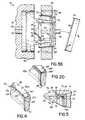
- FIG. 1is an exploded partially disassembled perspective view of the components of a molding apparatus for a molded closure according to a first presently preferred embodiment of this invention
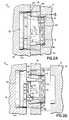
- FIG. 2Ais a cross-sectional view taken along line 2 — 2 of FIG. 1 showing the molding apparatus of FIG. 1 in a closed configuration;
- FIG. 2Bis a view similar to FIG. 2A with an outer mold being removed from the molded closure and a ring advancing the closure forwardly and the closure advancing slides on an inner mold core obliquely relative to the axis of the core;
- FIG. 2Cis a view similar to FIG. 2B with the projections on the skirt of the closure disengaging from recesses on the slides of the inner mold thereby releasing the closure from the inner mold;
- FIG. 2Dis an enlarged partial view of the ring of the molding apparatus of FIGS. 2A through 2C;
- FIG. 3Ais a view similar to FIG. 2A of an alternative embodiment of the molding apparatus of this invention for forming a closure with a tamper evident band;
- FIG. 3Bis a view of the molding apparatus of FIG. 3A with the closure being released from the inner mold by a plunger extending from the mold core;
- FIG. 4is an enlarged partial view of the ring of the molding apparatus of FIGS. 3A and 3B;
- FIG. 5is an enlarged cross-sectional view of the region 5 of FIG. 2A showing the projections on the skirt of the closure engaging the recesses on the slide of the inner mold.
- the molding apparatus 10includes an outer mold 12 having a socket 14 formed therein and an inner mold 16 including a mold core 18 and a plurality of slides 20 , four of which are shown in FIG. 1, mounted on the core 18 for movement relative to the core 18 in a direction obliquely oriented with respect to a longitudinal axis of the core 18 .
- the core 18includes a generally planar upper surface 22 and a tapered or sloped body 24 angled obliquely inwardly toward the upper surface 22 from a base 26 of the inner mold 16 .
- Each slide 20is mounted to the core 18 and seated within a tapered and sloped channel 28 having a generally planar face 30 bounded on each lateral side by a channel sidewall 32 .
- a guide boss 34projects from the face 30 of the channel 28 and has a generally T-shaped cross-sectional configuration in which a base 36 of the guide 34 is juxtaposed in face-to-face contact with the face 30 of the channel 28 and flanges 38 extend from the base 36 on either side of the guide 34 and are spaced from the face 30 of the channel 28 .
- the guide 34includes a pair of holes 40 , 42 and a screw, pin or other mechanical fastener is inserted through the lowermost hole 42 in the guide 34 to secure the guide 34 to the mold core 18 .
- a slide 20is mounted on the mold core 18 in each of the channels 28 and includes a generally planar back face 44 and a pair of sidewalls 46 extending obliquely from the back face 44 .
- the back face 44 and sidewalls 46 of the slide 20mate with the face 30 and sidewalls 32 of the channel 28 when the slide 20 is mounted on the core 18 .
- the spaced sidewalls 46 of the slide 20 (and the corresponding spaced sidewalls 32 of the channel 28 )are non-parallel with respect to each other to minimize friction between the slide 20 and the mold core 18 during movement of the slide 20 .
- a T-shaped slot 48 being open on a bottom edge of the slide 20is formed on the back face 44 of the slide 20 and is sized and configured to mate with the guide 34 mounted in the channel 28 .
- a recess 50is formed in a well 52 of the T-slot 48 on each slide 20 .
- a rim 54 of the recess 50serves a detent once the slide 20 is mounted in the channel 28 on the mold core 18 .
- the slide 20is mounted on the mold core 18 by sliding it downwardly so that the upper end of the guide 34 enters the open bottom end of the T-slot 48 and the respective sidewalls 32 , 46 and faces 30 , 44 of the slide 20 and channel 28 are in face-to-face juxtaposition until a bottom shelf 56 of the slide 20 is positioned within a seat 58 in the base 26 of the inner mold 16 .
- the guide 34has upper and lower holes 40 , 42 for receiving therein upper and lower screws, pins or other appropriate fasteners 60 , 62 .
- the upper and lower holes 40 , 42 in the guide 34are aligned with upper and lower through holes 64 , 66 in the slide 20 when the slide 20 is positioned on the mold core 18 with the shelf 56 contained in the seat 58 of the inner mold 16 .
- the lower screw 62is inserted through the lower through hole 66 in the slide 20 and into the lower hole 42 in the guide 34 to secure the guide 34 to the mold core 18 .
- the lower screw 62is flush or recessed with respect to an outer surface of the guide 34 .
- the upper screw 60is inserted through the upper through hole 64 in the slide 20 and is seated within the upper hole 40 in the guide 34 so that it projects from the outer surface of the guide 34 .
- the upper screw 60serves as a detent in combination with the rim 54 to prevent the slide 20 from sliding off of the mold core 18 .
- Upward movement of the slide 20is limited because the rim 54 in the recess 50 of the T-slot 48 on the slide 20 contacts the head of the uppermost screw 60 projecting from the outer surface of the guide 34 to thereby prevent the slide 20 from sliding off of the mold core 18 .
- the slides 20are limited to upward travel to the extent shown in the slides 20 attached to the core 18 in FIG. 1 .
- Each slide 20 in a presently preferred embodiment of the inventionhas a generally arcuate outer face 68 with a lower tapered section 70 and an upper section 72 having a plurality of recesses 74 formed therein.
- the mold 10 shown in FIG. 1is for forming a generally round or circular closure 76 although other configurations can be produced with appropriately designed molds 10 according to this invention.
- the recesses 74 in the upper section 72 of each slide 20form undercut projections 78 which extend inwardly from a skirt 80 of the closure 76 formed by the mold 10 (FIGS. 2A, 2 B and 5 ).
- the recesses 74 shown in the slides 20 of FIG. 1form intermittent or interrupted threads 78 on the closure 76 .
- the recesses 74include an undercut 82 which produces a corresponding undercut 84 on the projections or threads 78 of the closure 76 .
- the term “projection” or variations thereofmeans a thread of any kind, lug, stop, bayonet structure, rim or any other device which extends inwardly from the skirt 80 on the closure 76 and is formed by the recess 74 in the slide 20 .
- a molding apparatus 10also includes a ring 86 which is sized and configured to fit around the slides 20 and mold core 18 and to be positioned between the outer mold 12 and the inner mold 16 .
- the ring 86includes an upper surface 88 and a lower surface 90 and a plurality, four of which are shown in FIG. 1, of air ducts 92 are formed and spaced approximately 90° with respect to each other on the lower surface 90 of the ring 86 .
- the ducts 92are in communication with notches 94 on the inner surface of the ring 86 and permit air to escape from the molding apparatus 10 during the molding process.
- the outer mold 12 , inner mold 16 , ring 86 and various components of the molding apparatus 10 according to this inventioncan be contained within plates for use in a stack mold for the industrial production of closures 76 and other molded articles.
- a stack mold of this typeis shown in U.S. Pat. No. 4,019,711 and it will be appreciated by one of ordinary skill in the art that multiple molding systems according to this invention can be contained within a given stack mold for molding multiple closures 76 or other devices during a single operation.
- a first presently preferred method of molding a closure 76 according to this inventioninvolves injection molding and is shown in FIG. 2A-2C.
- the respective plates 96 , 98 , 100are juxtaposed in face-to-face configuration as shown in FIG. 2A to produce a closed configuration of the molding apparatus 10 .
- a cavity 102is formed between the inner mold 16 , the outer mold 12 and the ring 86 into which closure material for forming a closure 76 is introduced by injection into the cavity 102 as is readily known in the art.
- the closure materialmay be a variety of materials including styrene, polypropylene and any other thermoplastic resin or other appropriate composition. As is readily seen in FIG.
- the closure 76is formed between the outer mold 12 , specifically the socket 14 of the outer mold 12 , and the mold core 18 and the slides 20 on the mold core 18 .
- the upper surface 88 of the ring 86is in contact with a terminal edge 104 of the skirt 80 of the closure 76 .
- the molding apparatus 10converts to an open position when the outer mold 12 is removed from the ring 86 and the inner mold 16 once the closure material has had sufficient time to harden and solidify.
- the socket 14 in the other mold 12forms the outer external surface of the closure 76 including the outer surface of the skirt 80 and an upper panel 106 of the closure 76 .
- the mold 10continues to open by moving the ring 86 in a direction generally parallel to the longitudinal axis of the mold core 18 and away from the base 26 of the inner mold 16 .
- the ring 86moves in this direction, it maintains contact with the lower edge 104 of the skirt 80 of the closure 76 thereby moving the closure 76 with the ring 86 .
- the threads, lugs, rims, or other projections 78 formed on the inner surface of the skirt 80are seated within the recesses 74 in the slides 20 as shown in FIG. 2A and 2B.
- the movement of the closure 76 in response to the movement of the ring 86translates the slides 20 obliquely relative to the longitudinal axis of the mold core 18 .
- the closure 76is the mechanism for moving the slides 20 relative to the mold core 18 .
- the slides 20are movable axially from and angling radially inwardly towards the longitudinal axis of the mold core 18 as shown in FIGS. 1-2C from the closed position of the mold 10 to the open position of the mold 10 as shown in FIG. 2 C.
- the recesses 74 in the slides 20move in two vectors.
- the recesses 74are moved in a first direction generally parallel to the longitudinal axis of the mold core 18 forcing the slides 20 to the right as shown in FIG. 2A and 2B.
- the present inventionprovides an effective mechanism for first injection molding a closure 76 having threads, lugs, rims or other projections 78 extending radially inward from the skirt 80 and removing the closure 76 from the inner mold 16 without deformation of the projections 78 .
- the ring 86may include an upper groove 124 adjacent the upper surface 88 of the ring 86 above a rib 126 .
- the upper groove 124positions and centers the closure 76 in the molding apparatus 10 by forming and or engaging a lower edge of the skirt 80 of the closure 76 .
- the molding apparatus 10 of this inventionis used for compression molding the closure 76 or the like.
- Polypropylene powder, resin or other appropriate materialis introduced or placed in the cavity 102 of the molding apparatus 10 which is then heated to cure the molding material.
- the resulting closure 76is then ejected from the mold 10 in a manner similar to that previously described with respect to the injection molding process (FIGS. 2 A- 2 C).
- other molding techniquesin addition to injection and compression could be utilized with the molding apparatus 10 within the scope of this invention.
- Known collapsing moldsoften include complicated mechanisms, springs or other biasing systems for moving the slides relative to the mold core.
- the present inventionavoids the need for any such complicated mechanisms and the maintenance and reliability problems associated therewith.
- the movement of the slides 20is independent from the movement of the ring 86 .
- the ring 86is free to translate relative to the slides 20 in the forward direction in the absence of the closure 76 seated on the inner mold 16 .
- the mechanism for translating the slides 20 towards the open position shown in FIG. 2Cis the engagement of the projections 78 on the skirt 80 of the closure 76 and the recesses 74 on the slides 20 .
- the molding apparatus 10 and method according to this inventionenables the formation of undercut projections 78 on the closure 76 without damage to those projections 78 during the release of the closure 76 from the mold 10 .
- the intermittent threads 78include an undercut surface 84 and an arcuate or rounded surface 108 in combination therewith.
- the undercut 84forms an angle with respect to the skirt 80 from between approximately 82° and 90°.
- a retaining rim 110also having an undercut surface 112 may be formed by the recesses 74 and slides 20 on the mold 10 according to this invention.
- the retaining rim 110is one specific projection 78 and is positioned adjacent the panel 106 of the closure 76 and spaced therefrom.
- the retaining rim 110may be interrupted or intermittent similar to the threads 78 formed on the skirt 80 .
- the retaining rim 110is used to secure a sealing disk (not shown) in the closure 76 in generally face-to-face contact with the lower surface of the panel 106 as is readily known in the art.
- the retaining rim 110secures the disk to the closure 76 in a press-fit or friction-fit without the need for adhesive, glue or the like.
- FIGS. 3A, 3 B and 4A second presently preferred embodiment of the molding apparatus 10 and method for molding a closure 76 according to this invention is shown in FIGS. 3A, 3 B and 4 . Elements of this presently preferred embodiment similar to corresponding elements in the previously described preferred embodiment are identified with the same reference numerals.
- This presently preferred embodiment of this inventionis particularly adapted for injection, compression or otherwise molding a closure 76 having a tamper evident band 114 attached via frangible spaced bridges 116 to the terminal lower edge 104 of the skirt 80 (FIG. 3 B).
- the molding apparatus 10further includes a plunger 118 axially extendable from the inner mold 16 to project from the upper face 22 of the mold core 18 .
- the plunger 118is generally aligned with the longitudinal axis of the inner mold 16 .
- the intaglio pattern 122includes an upper groove 124 adjacent the upper surface 88 a of the ring 86 a , a rib 126 and a lower groove 128 .
- the intaglio pattern 122provides a relief for the formation of the tamper evident band 114 and frangible bridges 116 on the closure 76 .
- the lower groove 128forms the band 114 and a plurality of spaced flutes 130 connecting the upper groove 124 to the lower groove 128 form the frangible bridges 116 of the closure 76 according to this embodiment of the invention.
- the ring 86 a of this embodiment of the inventionforms the tamper evident band 114 and engages the closure 76 as the ring 86 a is translated away from the base 26 of the inner mold 16 thereby advancing the closure 76 and the slides 20 in contact with the closure 76 as previously described with reference to FIGS. 2A-2C.
- the plunger 118is extended to contact the panel 106 of the closure 76 and disengage the tamper evident band 114 from the ring 86 a and thereby release the closure 76 from the mold 10 as shown in FIG. 3 B.
- a chamfer 89extending around the ring 86 a proximate the upper surface 88 a thereof.
- the chamfer 89holds the closure 76 in the center of the ring 86 a for alignment in the molding apparatus 10 .
- the centering of the closure 76 relative to the ring 86 a with the chamfer 89has proven to be an important feature for the present invention.
- the tamper evident band forming ring 86 a of the second presently preferred embodimentcan be easily and quickly replaced as required with the ring 86 of the first presently preferred embodiment while the inner and outer molds 16 , 12 remain unchanged.
- the production capability for selectively manufacturing closures 76 with or without tamper evident bands 114is much more efficient according to this invention.
- the plunger 118 or a plurality of plungersmay be included with the tamper evident band forming ring or the ring 86 shown in FIGS. 2A-2C. Additionally, the plunger 118 or plungers may be used as the mechanism for advancing the closure 76 in addition to or instead of the movement of the ring 86 or 86 a .
- extension of the plunger 118 to contact the panel 106 of the closure 76 and thereby move the closure 76 away from the mold core 18results in the movement of the slides 20 toward the longitudinal axis of the mold core 18 and ultimately disengages the recesses 74 on the slides 20 from the projections 78 on the skirt 80 .
- the movement of the plunger 118 alone or in combination with the movement of the ring 86 or 86 acan be the mechanism for moving the slides 20 .
- the components of the molding apparatus 10are then reassembled into the closed configuration.
- the ring 86 or 86 ais moved towards the inner mold base 26 , the lower surface 90 of the ring 86 or 86 a contacts the upper surface of the shelf 56 on each slide 20 thereby translating the slide 20 toward the closed configuration of the mold 10 .
Landscapes
- Engineering & Computer Science (AREA)
- Manufacturing & Machinery (AREA)
- Mechanical Engineering (AREA)
- Moulds For Moulding Plastics Or The Like (AREA)
- Closures For Containers (AREA)
Abstract
Description
Claims (20)
Priority Applications (1)
| Application Number | Priority Date | Filing Date | Title |
|---|---|---|---|
| US09/578,367US6506330B1 (en) | 1998-03-17 | 2000-05-25 | Apparatus and method for molding plastic closures |
Applications Claiming Priority (2)
| Application Number | Priority Date | Filing Date | Title |
|---|---|---|---|
| US09/042,699US6099785A (en) | 1998-03-17 | 1998-03-17 | Method for injection molding plastic closures |
| US09/578,367US6506330B1 (en) | 1998-03-17 | 2000-05-25 | Apparatus and method for molding plastic closures |
Related Parent Applications (1)
| Application Number | Title | Priority Date | Filing Date |
|---|---|---|---|
| US09/042,699Continuation-In-PartUS6099785A (en) | 1998-03-17 | 1998-03-17 | Method for injection molding plastic closures |
Publications (1)
| Publication Number | Publication Date |
|---|---|
| US6506330B1true US6506330B1 (en) | 2003-01-14 |
Family
ID=46279680
Family Applications (1)
| Application Number | Title | Priority Date | Filing Date |
|---|---|---|---|
| US09/578,367Expired - Fee RelatedUS6506330B1 (en) | 1998-03-17 | 2000-05-25 | Apparatus and method for molding plastic closures |
Country Status (1)
| Country | Link |
|---|---|
| US (1) | US6506330B1 (en) |
Cited By (23)
| Publication number | Priority date | Publication date | Assignee | Title |
|---|---|---|---|---|
| US20050154184A1 (en)* | 2004-01-09 | 2005-07-14 | The Coca-Cola Company | Condensation compression molding process and apparatus for production of container preforms |
| US20050266115A1 (en)* | 2004-05-28 | 2005-12-01 | Vince Ciccone | Injection mold |
| US20060034973A1 (en)* | 2002-11-05 | 2006-02-16 | Hoogland Hendricus A | Apparatus and method for manufacturing holders, in particular crates |
| US20060188602A1 (en)* | 2005-02-18 | 2006-08-24 | Garry Zydron | Collapsible core assembly for a molding apparatus |
| US20070295887A1 (en)* | 2006-06-27 | 2007-12-27 | Fu Chin Kuo | Lipstick making device |
| US20080124421A1 (en)* | 2006-11-06 | 2008-05-29 | Dixie Consumer Products Llc | Lightweight Knockout For Forming Die Assembly |
| US20090121115A1 (en)* | 2007-11-13 | 2009-05-14 | Garry Zydron | Collapsible core assembly for a molding apparatus |
| US20100098800A1 (en)* | 2007-02-21 | 2010-04-22 | Sacmi Cooperativa Meccanici Imola Societa' Coopera | Mould device for forming objects made of plastics |
| USD631073S1 (en)* | 2010-08-12 | 2011-01-18 | Husky Injection Molding Systems Ltd. | Core ring for use in a mold stack |
| US20120235325A1 (en)* | 2011-03-11 | 2012-09-20 | Progressive Components International Corporation | Collapsing core part retainer sleeve |
| US20130202731A1 (en)* | 2012-02-08 | 2013-08-08 | Shin Tai Plastics Industrial Co., Ltd. | Structure of slide-block module of a plastic pallet shaping mold |
| US8585392B2 (en) | 2011-05-24 | 2013-11-19 | F&S Tool, Inc. | Compression molding with successive stage cooling channels |
| US8602768B2 (en)* | 2010-06-11 | 2013-12-10 | Irumold, S.L. | Mould for moulded parts with internal undercuts |
| USD733198S1 (en)* | 2013-10-24 | 2015-06-30 | Paradise Mold and Die LLC | Set of six components of a collapsible core of a mold |
| USD741921S1 (en)* | 2014-04-15 | 2015-10-27 | Q-Linea Ab | Positive mold for manufacturing a sample holding disc |
| US9808975B2 (en) | 2013-10-24 | 2017-11-07 | Paradise Mold and Die LLC | Collapsible core of a mold for forming internal features such as threads |
| US11052582B1 (en)* | 2018-05-02 | 2021-07-06 | Versevo, Inc. | Collapsible core devices and method for injection molding |
| CN115635656A (en)* | 2022-09-09 | 2023-01-24 | 昆山欧德斯电子科技有限公司 | Delayed core-pulling draft mold for preparing double-helix threaded connection seat |
| US20230149959A1 (en)* | 2019-06-24 | 2023-05-18 | Silgan Dispensing Systems Le Treport | Methods of making a fastening system for a distribution member on a threaded neck of a reservoir |
| US20240025097A1 (en)* | 2022-07-22 | 2024-01-25 | Shenzhen Zhongfuneng Electric Equipment Co., Ltd | Injection mold, transparent plastic part and injection molding method |
| SE2350453A1 (en)* | 2023-04-17 | 2024-10-18 | Blue Ocean Closures Ab | Press molding method including a collapsible stamp member for producing a cup shaped fiber product |
| US20250018638A1 (en)* | 2023-07-12 | 2025-01-16 | Ring Container Technologies,Llc | Packaging container manufacturing system and method |
| CN119388683A (en)* | 2024-11-29 | 2025-02-07 | 宁波德科精密模塑有限公司 | A helmet cover inner bracket mold |
Citations (62)
| Publication number | Priority date | Publication date | Assignee | Title |
|---|---|---|---|---|
| US2583093A (en) | 1949-01-26 | 1952-01-22 | Fed Tool Corp | Apparatus for making closures for containers |
| US2718032A (en) | 1951-10-25 | 1955-09-20 | Wilfred G Harvey | Knockout mechanism for molding dies |
| US3125801A (en) | 1964-03-24 | fields | ||
| US3339242A (en) | 1963-11-12 | 1967-09-05 | Ketch Plastics Ltd | Collapsible tools for use in the moulding, casting or pressing of hollow articles |
| US3344942A (en) | 1966-04-05 | 1967-10-03 | Hedgewick Peter | Safety cap and container |
| US3555606A (en) | 1968-09-16 | 1971-01-19 | Reflex Corp Canada Ltd | Molding apparatus for making one-piece plastic caps for containers |
| US3586196A (en) | 1969-11-03 | 1971-06-22 | Mead Johnson & Co | Nurser |
| US3612325A (en) | 1968-06-19 | 1971-10-12 | Dover Molded Products Co | Plastic screwcap with rotatable washer |
| US3618170A (en) | 1969-07-14 | 1971-11-09 | Edward W Owens | Apparatus for molding plastic closures |
| USRE28158E (en) | 1973-06-26 | 1974-09-17 | Displacement molding plastic articles | |
| US3865529A (en) | 1973-12-05 | 1975-02-11 | Beatrice Foods Co | Molding apparatus |
| US3905740A (en) | 1973-11-19 | 1975-09-16 | Beatrice Foods Co | Molding apparatus |
| US4019711A (en) | 1975-11-10 | 1977-04-26 | J & J Tool And Mold Ltd. | Mould for closure caps with intermittent threads undercuts or hold-down lugs |
| US4046282A (en) | 1975-06-27 | 1977-09-06 | Albert Obrist & Co. | Molded plastic covers for containers |
| US4093094A (en) | 1977-03-28 | 1978-06-06 | Owens-Illinois, Inc. | Home canning system |
| US4109815A (en) | 1976-12-08 | 1978-08-29 | Aluminum Company Of America | Induction heat sealed containers |
| US4123495A (en) | 1976-01-12 | 1978-10-31 | Bud Antle, Inc. | Method for making molded articles of expanded cellular material |
| US4170316A (en) | 1974-12-05 | 1979-10-09 | Labarbera Mannie | Over-cap closure device |
| GB1589051A (en) | 1977-08-19 | 1981-05-07 | Plastiers Ltd | Gutter fittings |
| US4378893A (en) | 1979-09-21 | 1983-04-05 | H-C Industries, Inc. | Composite closure |
| US4381840A (en) | 1981-08-24 | 1983-05-03 | Ethyl Products Company | Threaded closure with free-floating liner |
| US4383819A (en) | 1980-07-16 | 1983-05-17 | Letica Corporation | Apparatus for forming a container |
| US4407422A (en) | 1981-06-04 | 1983-10-04 | H-C Industries, Inc. | Composite closure |
| US4462502A (en) | 1980-12-22 | 1984-07-31 | Ethyl Molded Products Company | Threaded closure with liner |
| US4497765A (en) | 1979-09-21 | 1985-02-05 | H-C Industries, Inc. | Process for making a closure |
| US4502660A (en) | 1983-11-21 | 1985-03-05 | Luther Leroy D | Mold including side walls with locking projections |
| US4525130A (en) | 1984-05-07 | 1985-06-25 | Netznik Frederick P | Adjustable molding frame |
| US4533312A (en) | 1982-12-27 | 1985-08-06 | Holdt J W Von | Simplified collapsible mold core |
| US4541605A (en) | 1983-02-16 | 1985-09-17 | Daiichi-Geyer Kabushiki Kaisha | Metal mold device |
| US4552328A (en) | 1984-01-05 | 1985-11-12 | Sun Coast Plastics, Inc. | Mold for making tamper-proof closure |
| US4618121A (en) | 1984-08-15 | 1986-10-21 | American Safety Closure Corp. | Mold for forming plastic cap with perforation about the periphery of the skirt |
| US4627810A (en) | 1985-09-26 | 1986-12-09 | Holdt J W Von | Collapsible core |
| US4629083A (en) | 1983-06-23 | 1986-12-16 | Bev-Cap Plastics Pty. Ltd. | Closure with resilient sealing disc |
| US4648520A (en) | 1985-06-11 | 1987-03-10 | Gene Stull | Cap and means for retaining cap liner |
| US4664280A (en) | 1985-04-16 | 1987-05-12 | H-C Industries, Inc. | Composite closure |
| US4674642A (en) | 1984-09-07 | 1987-06-23 | Tbl Development Corporation | Pressure-indicative container closure |
| US4676732A (en) | 1985-09-26 | 1987-06-30 | Letica Corporation | Molding apparatus |
| US4708632A (en) | 1983-12-29 | 1987-11-24 | I.F.W.-Industrie-Formen Und Werkzeugbau-Manfred Otte Gesellschaft M.B.H. & Co. Kg. | Injection moulding mould |
| US4731014A (en) | 1986-03-12 | 1988-03-15 | Holdt J W Von | Rear opening mold |
| US4782968A (en) | 1987-04-20 | 1988-11-08 | Anchor Hocking Corporation | Composite closure and method of manufacture |
| US4806301A (en) | 1984-08-15 | 1989-02-21 | American Safety Closure Corp. | Process of removing a plastic cap from a mold |
| US4832307A (en) | 1988-09-15 | 1989-05-23 | Toshiba Kikai Kabushiki Kaisha | Injection mold |
| US4854849A (en) | 1986-10-31 | 1989-08-08 | Mazda Motor Corporation | Injection mold |
| US4881891A (en) | 1989-01-11 | 1989-11-21 | Triangle Tool Corporation | Mold side wall locking apparatus |
| US4919608A (en) | 1988-10-04 | 1990-04-24 | Roehr Tool Corporation | Molding apparatus with collapsible core |
| JPH03222642A (en) | 1990-01-25 | 1991-10-01 | Nec Gumma Ltd | Rotor of radial gap motor |
| US5053182A (en) | 1989-09-05 | 1991-10-01 | Caran Engineering Investments, Inc. | One piece safety cap molding apparatus and method |
| US5064084A (en) | 1990-08-27 | 1991-11-12 | H-C Industries, Inc. | Composite closure with seal proportioning lip |
| US5137442A (en) | 1991-02-07 | 1992-08-11 | D & L Incorporated | Universal internal core lifter apparatus |
| US5230856A (en) | 1990-05-21 | 1993-07-27 | Frank Schellenbach | Method for demolding a safety-seal strip of a closure cap |
| US5232718A (en) | 1990-09-29 | 1993-08-03 | Nissei Asb Machine Co., Ltd. | Injection molding system for making preform with undercut |
| US5281385A (en) | 1992-10-21 | 1994-01-25 | Sunbeam Plastics Corporation | Injection molding system for threaded tamper indicating closures |
| US5281127A (en) | 1992-05-14 | 1994-01-25 | Ramsey William C | Articulated core blade assembly for use in an injection molding machine |
| US5368469A (en) | 1993-08-26 | 1994-11-29 | Phoenix Closures, Inc. | Apparatus for molding closures having tamper evident bands |
| US5383780A (en) | 1993-09-27 | 1995-01-24 | Husky Injection Molding Systems Ltd. | Apparatus for forming threaded molded article |
| US5403179A (en) | 1993-10-29 | 1995-04-04 | Ramsey; William C. | Collapsible mold core assembly |
| US5447674A (en) | 1987-06-04 | 1995-09-05 | Schellenbach; Frank | Method for producing a gas-tight plastic closure for containers |
| US5551864A (en) | 1995-01-12 | 1996-09-03 | Boskovic; Borislav | Core lifter system |
| US5603968A (en) | 1994-04-28 | 1997-02-18 | Toyoda Gosei Co., Ltd. | Apparatus for manufacturing a steering wheel pad |
| US5609894A (en) | 1995-02-27 | 1997-03-11 | Rathbun Family Real Estate Group | Injection molding apparatus for producing plastic lids |
| US5630977A (en) | 1993-12-23 | 1997-05-20 | Roehr Tool Corporation | Injection molding method and system with expandable cavity element |
| US5925303A (en) | 1995-02-09 | 1999-07-20 | Unique Mould Makers Limited | Process for forming seamless molded skirt |
- 2000
- 2000-05-25USUS09/578,367patent/US6506330B1/ennot_activeExpired - Fee Related
Patent Citations (62)
| Publication number | Priority date | Publication date | Assignee | Title |
|---|---|---|---|---|
| US3125801A (en) | 1964-03-24 | fields | ||
| US2583093A (en) | 1949-01-26 | 1952-01-22 | Fed Tool Corp | Apparatus for making closures for containers |
| US2718032A (en) | 1951-10-25 | 1955-09-20 | Wilfred G Harvey | Knockout mechanism for molding dies |
| US3339242A (en) | 1963-11-12 | 1967-09-05 | Ketch Plastics Ltd | Collapsible tools for use in the moulding, casting or pressing of hollow articles |
| US3344942A (en) | 1966-04-05 | 1967-10-03 | Hedgewick Peter | Safety cap and container |
| US3612325A (en) | 1968-06-19 | 1971-10-12 | Dover Molded Products Co | Plastic screwcap with rotatable washer |
| US3555606A (en) | 1968-09-16 | 1971-01-19 | Reflex Corp Canada Ltd | Molding apparatus for making one-piece plastic caps for containers |
| US3618170A (en) | 1969-07-14 | 1971-11-09 | Edward W Owens | Apparatus for molding plastic closures |
| US3586196A (en) | 1969-11-03 | 1971-06-22 | Mead Johnson & Co | Nurser |
| USRE28158E (en) | 1973-06-26 | 1974-09-17 | Displacement molding plastic articles | |
| US3905740A (en) | 1973-11-19 | 1975-09-16 | Beatrice Foods Co | Molding apparatus |
| US3865529A (en) | 1973-12-05 | 1975-02-11 | Beatrice Foods Co | Molding apparatus |
| US4170316A (en) | 1974-12-05 | 1979-10-09 | Labarbera Mannie | Over-cap closure device |
| US4046282A (en) | 1975-06-27 | 1977-09-06 | Albert Obrist & Co. | Molded plastic covers for containers |
| US4019711A (en) | 1975-11-10 | 1977-04-26 | J & J Tool And Mold Ltd. | Mould for closure caps with intermittent threads undercuts or hold-down lugs |
| US4123495A (en) | 1976-01-12 | 1978-10-31 | Bud Antle, Inc. | Method for making molded articles of expanded cellular material |
| US4109815A (en) | 1976-12-08 | 1978-08-29 | Aluminum Company Of America | Induction heat sealed containers |
| US4093094A (en) | 1977-03-28 | 1978-06-06 | Owens-Illinois, Inc. | Home canning system |
| GB1589051A (en) | 1977-08-19 | 1981-05-07 | Plastiers Ltd | Gutter fittings |
| US4497765A (en) | 1979-09-21 | 1985-02-05 | H-C Industries, Inc. | Process for making a closure |
| US4378893A (en) | 1979-09-21 | 1983-04-05 | H-C Industries, Inc. | Composite closure |
| US4383819A (en) | 1980-07-16 | 1983-05-17 | Letica Corporation | Apparatus for forming a container |
| US4462502A (en) | 1980-12-22 | 1984-07-31 | Ethyl Molded Products Company | Threaded closure with liner |
| US4407422A (en) | 1981-06-04 | 1983-10-04 | H-C Industries, Inc. | Composite closure |
| US4381840A (en) | 1981-08-24 | 1983-05-03 | Ethyl Products Company | Threaded closure with free-floating liner |
| US4533312A (en) | 1982-12-27 | 1985-08-06 | Holdt J W Von | Simplified collapsible mold core |
| US4541605A (en) | 1983-02-16 | 1985-09-17 | Daiichi-Geyer Kabushiki Kaisha | Metal mold device |
| US4629083A (en) | 1983-06-23 | 1986-12-16 | Bev-Cap Plastics Pty. Ltd. | Closure with resilient sealing disc |
| US4502660A (en) | 1983-11-21 | 1985-03-05 | Luther Leroy D | Mold including side walls with locking projections |
| US4708632A (en) | 1983-12-29 | 1987-11-24 | I.F.W.-Industrie-Formen Und Werkzeugbau-Manfred Otte Gesellschaft M.B.H. & Co. Kg. | Injection moulding mould |
| US4552328A (en) | 1984-01-05 | 1985-11-12 | Sun Coast Plastics, Inc. | Mold for making tamper-proof closure |
| US4525130A (en) | 1984-05-07 | 1985-06-25 | Netznik Frederick P | Adjustable molding frame |
| US4618121A (en) | 1984-08-15 | 1986-10-21 | American Safety Closure Corp. | Mold for forming plastic cap with perforation about the periphery of the skirt |
| US4806301A (en) | 1984-08-15 | 1989-02-21 | American Safety Closure Corp. | Process of removing a plastic cap from a mold |
| US4674642A (en) | 1984-09-07 | 1987-06-23 | Tbl Development Corporation | Pressure-indicative container closure |
| US4664280A (en) | 1985-04-16 | 1987-05-12 | H-C Industries, Inc. | Composite closure |
| US4648520A (en) | 1985-06-11 | 1987-03-10 | Gene Stull | Cap and means for retaining cap liner |
| US4676732A (en) | 1985-09-26 | 1987-06-30 | Letica Corporation | Molding apparatus |
| US4627810A (en) | 1985-09-26 | 1986-12-09 | Holdt J W Von | Collapsible core |
| US4731014A (en) | 1986-03-12 | 1988-03-15 | Holdt J W Von | Rear opening mold |
| US4854849A (en) | 1986-10-31 | 1989-08-08 | Mazda Motor Corporation | Injection mold |
| US4782968A (en) | 1987-04-20 | 1988-11-08 | Anchor Hocking Corporation | Composite closure and method of manufacture |
| US5447674A (en) | 1987-06-04 | 1995-09-05 | Schellenbach; Frank | Method for producing a gas-tight plastic closure for containers |
| US4832307A (en) | 1988-09-15 | 1989-05-23 | Toshiba Kikai Kabushiki Kaisha | Injection mold |
| US4919608A (en) | 1988-10-04 | 1990-04-24 | Roehr Tool Corporation | Molding apparatus with collapsible core |
| US4881891A (en) | 1989-01-11 | 1989-11-21 | Triangle Tool Corporation | Mold side wall locking apparatus |
| US5053182A (en) | 1989-09-05 | 1991-10-01 | Caran Engineering Investments, Inc. | One piece safety cap molding apparatus and method |
| JPH03222642A (en) | 1990-01-25 | 1991-10-01 | Nec Gumma Ltd | Rotor of radial gap motor |
| US5230856A (en) | 1990-05-21 | 1993-07-27 | Frank Schellenbach | Method for demolding a safety-seal strip of a closure cap |
| US5064084A (en) | 1990-08-27 | 1991-11-12 | H-C Industries, Inc. | Composite closure with seal proportioning lip |
| US5232718A (en) | 1990-09-29 | 1993-08-03 | Nissei Asb Machine Co., Ltd. | Injection molding system for making preform with undercut |
| US5137442A (en) | 1991-02-07 | 1992-08-11 | D & L Incorporated | Universal internal core lifter apparatus |
| US5281127A (en) | 1992-05-14 | 1994-01-25 | Ramsey William C | Articulated core blade assembly for use in an injection molding machine |
| US5281385A (en) | 1992-10-21 | 1994-01-25 | Sunbeam Plastics Corporation | Injection molding system for threaded tamper indicating closures |
| US5368469A (en) | 1993-08-26 | 1994-11-29 | Phoenix Closures, Inc. | Apparatus for molding closures having tamper evident bands |
| US5383780A (en) | 1993-09-27 | 1995-01-24 | Husky Injection Molding Systems Ltd. | Apparatus for forming threaded molded article |
| US5403179A (en) | 1993-10-29 | 1995-04-04 | Ramsey; William C. | Collapsible mold core assembly |
| US5630977A (en) | 1993-12-23 | 1997-05-20 | Roehr Tool Corporation | Injection molding method and system with expandable cavity element |
| US5603968A (en) | 1994-04-28 | 1997-02-18 | Toyoda Gosei Co., Ltd. | Apparatus for manufacturing a steering wheel pad |
| US5551864A (en) | 1995-01-12 | 1996-09-03 | Boskovic; Borislav | Core lifter system |
| US5925303A (en) | 1995-02-09 | 1999-07-20 | Unique Mould Makers Limited | Process for forming seamless molded skirt |
| US5609894A (en) | 1995-02-27 | 1997-03-11 | Rathbun Family Real Estate Group | Injection molding apparatus for producing plastic lids |
Cited By (35)
| Publication number | Priority date | Publication date | Assignee | Title |
|---|---|---|---|---|
| US20060034973A1 (en)* | 2002-11-05 | 2006-02-16 | Hoogland Hendricus A | Apparatus and method for manufacturing holders, in particular crates |
| US20050154184A1 (en)* | 2004-01-09 | 2005-07-14 | The Coca-Cola Company | Condensation compression molding process and apparatus for production of container preforms |
| US20050266115A1 (en)* | 2004-05-28 | 2005-12-01 | Vince Ciccone | Injection mold |
| US7186112B2 (en)* | 2004-05-28 | 2007-03-06 | Injectnotech Inc. | Injection mold for forming crimp-on pour spouts |
| US20060188602A1 (en)* | 2005-02-18 | 2006-08-24 | Garry Zydron | Collapsible core assembly for a molding apparatus |
| US20060188601A1 (en)* | 2005-02-18 | 2006-08-24 | Mr. Garry Zydron | Collapsible core using two sleeves and is spring loaded |
| US7293341B2 (en) | 2005-02-18 | 2007-11-13 | Progressive Components International Corporation | Collapsible core assembly for a molding apparatus |
| US7381046B2 (en)* | 2006-06-27 | 2008-06-03 | Fu Chin Kuo | Lipstick making device |
| US20070295887A1 (en)* | 2006-06-27 | 2007-12-27 | Fu Chin Kuo | Lipstick making device |
| US20080124421A1 (en)* | 2006-11-06 | 2008-05-29 | Dixie Consumer Products Llc | Lightweight Knockout For Forming Die Assembly |
| US7845935B2 (en)* | 2006-11-06 | 2010-12-07 | Dixie Consumer Products Llc | Lightweight knockout for forming die assembly |
| US20100098800A1 (en)* | 2007-02-21 | 2010-04-22 | Sacmi Cooperativa Meccanici Imola Societa' Coopera | Mould device for forming objects made of plastics |
| US20090121115A1 (en)* | 2007-11-13 | 2009-05-14 | Garry Zydron | Collapsible core assembly for a molding apparatus |
| US8002538B2 (en) | 2007-11-13 | 2011-08-23 | Garry Zydron | Collapsible core assembly for a molding apparatus |
| US8602768B2 (en)* | 2010-06-11 | 2013-12-10 | Irumold, S.L. | Mould for moulded parts with internal undercuts |
| USD631073S1 (en)* | 2010-08-12 | 2011-01-18 | Husky Injection Molding Systems Ltd. | Core ring for use in a mold stack |
| US20120235325A1 (en)* | 2011-03-11 | 2012-09-20 | Progressive Components International Corporation | Collapsing core part retainer sleeve |
| EP2683538A4 (en)* | 2011-03-11 | 2015-01-14 | Progressive Components Int | KEY CORE PART RETAINING ELEMENT SLEEVE |
| US9011138B2 (en)* | 2011-03-11 | 2015-04-21 | Progressive Components International Corporation | Collapsing core part retainer sleeve |
| US9475246B2 (en) | 2011-05-24 | 2016-10-25 | F&S Tool, Inc. | Method of molding and mold with succesive stage cooling channels |
| US8585392B2 (en) | 2011-05-24 | 2013-11-19 | F&S Tool, Inc. | Compression molding with successive stage cooling channels |
| US8758007B2 (en)* | 2012-02-08 | 2014-06-24 | Shin Tai Plastics Industrial Co., Ltd. | Structure of slide-block module of a plastic pallet shaping mold |
| US20130202731A1 (en)* | 2012-02-08 | 2013-08-08 | Shin Tai Plastics Industrial Co., Ltd. | Structure of slide-block module of a plastic pallet shaping mold |
| USD733198S1 (en)* | 2013-10-24 | 2015-06-30 | Paradise Mold and Die LLC | Set of six components of a collapsible core of a mold |
| US9808975B2 (en) | 2013-10-24 | 2017-11-07 | Paradise Mold and Die LLC | Collapsible core of a mold for forming internal features such as threads |
| USD741921S1 (en)* | 2014-04-15 | 2015-10-27 | Q-Linea Ab | Positive mold for manufacturing a sample holding disc |
| US11052582B1 (en)* | 2018-05-02 | 2021-07-06 | Versevo, Inc. | Collapsible core devices and method for injection molding |
| US20230149959A1 (en)* | 2019-06-24 | 2023-05-18 | Silgan Dispensing Systems Le Treport | Methods of making a fastening system for a distribution member on a threaded neck of a reservoir |
| US12434255B2 (en)* | 2019-06-24 | 2025-10-07 | Silgan Dispensing Systems Le Treport | Methods of making a fastening system for a distribution member on a threaded neck of a reservoir |
| US20240025097A1 (en)* | 2022-07-22 | 2024-01-25 | Shenzhen Zhongfuneng Electric Equipment Co., Ltd | Injection mold, transparent plastic part and injection molding method |
| CN115635656A (en)* | 2022-09-09 | 2023-01-24 | 昆山欧德斯电子科技有限公司 | Delayed core-pulling draft mold for preparing double-helix threaded connection seat |
| SE2350453A1 (en)* | 2023-04-17 | 2024-10-18 | Blue Ocean Closures Ab | Press molding method including a collapsible stamp member for producing a cup shaped fiber product |
| SE547108C2 (en)* | 2023-04-17 | 2025-04-22 | Blue Ocean Closures Ab | Press molding method including a collapsible stamp member for producing a cup shaped fiber product |
| US20250018638A1 (en)* | 2023-07-12 | 2025-01-16 | Ring Container Technologies,Llc | Packaging container manufacturing system and method |
| CN119388683A (en)* | 2024-11-29 | 2025-02-07 | 宁波德科精密模塑有限公司 | A helmet cover inner bracket mold |
Similar Documents
| Publication | Publication Date | Title |
|---|---|---|
| US6099785A (en) | Method for injection molding plastic closures | |
| US6506330B1 (en) | Apparatus and method for molding plastic closures | |
| US3940103A (en) | Apparatus for injection molding a tamper-proof plastic cap | |
| US11801976B2 (en) | Containers and closures | |
| US4046282A (en) | Molded plastic covers for containers | |
| US3344942A (en) | Safety cap and container | |
| RU2310563C2 (en) | Apparatus for extracting article out of mold | |
| US5383780A (en) | Apparatus for forming threaded molded article | |
| US4531703A (en) | Mold permitting air ejection of a flanged article | |
| CN101568473A (en) | Semi-finished product for producing an opening apparatus | |
| EP1179407B1 (en) | Apparatus and method for molding plastic closures | |
| US6245277B1 (en) | Injection mold assembly for molding plastic containers | |
| GB1478420A (en) | Apparatus for moulding safety caps | |
| KR101036398B1 (en) | Apparatus for forming plastic plugs with air assisted discharge | |
| US3482814A (en) | Mold apparatus for making safety caps | |
| US5833912A (en) | Method of injection molding a container | |
| US5240719A (en) | One piece safety cap molding apparatus | |
| KR101646640B1 (en) | Injection mold having an undercut forming a ring that is moved to the inside or outside | |
| EP0396689B1 (en) | A sealing arrangement for an adhesive dispenser | |
| CN116096546A (en) | Plastic injection mold for producing a closure and method for producing a closure | |
| US6171542B1 (en) | Method and apparatus for the manufacture of blown plastic containers | |
| JP3570531B2 (en) | Injection mold for synthetic resin cap | |
| US20030146546A1 (en) | Injection mold for plastic caps, with carriage | |
| JP4060457B2 (en) | Compression molding equipment for synthetic resin articles | |
| CN120813460A (en) | Closure and mold assembly for making the same |
Legal Events
| Date | Code | Title | Description |
|---|---|---|---|
| AS | Assignment | Owner name:DELTA PLASTICS, INC., ARKANSAS Free format text:ASSIGNMENT OF ASSIGNORS INTEREST;ASSIGNORS:SCHWEIGERT, LOTHAR;O, UI HWAN;REEL/FRAME:014154/0782;SIGNING DATES FROM 20030503 TO 20030508 | |
| AS | Assignment | Owner name:MADISON CAPITAL FUNDING, LLC, ILLINOIS Free format text:SECURITY AGREEMENT;ASSIGNOR:DELTA PLASTICS, INC.;REEL/FRAME:014154/0777 Effective date:20030606 | |
| AS | Assignment | Owner name:DELTA PLASTICS, INC., ARKANSAS Free format text:RELEASE BY SECURED PARTY;ASSIGNOR:MADISON CAPITAL FUNDING LLC;REEL/FRAME:016570/0160 Effective date:20050919 | |
| FEPP | Fee payment procedure | Free format text:PAT HOLDER NO LONGER CLAIMS SMALL ENTITY STATUS, ENTITY STATUS SET TO UNDISCOUNTED (ORIGINAL EVENT CODE: STOL); ENTITY STATUS OF PATENT OWNER: LARGE ENTITY | |
| FPAY | Fee payment | Year of fee payment:4 | |
| FPAY | Fee payment | Year of fee payment:8 | |
| AS | Assignment | Owner name:BERRY PLASTICS CORPORATION, INDIANA Free format text:ASSIGNMENT OF ASSIGNORS INTEREST;ASSIGNOR:DELTA PLASTICS INC.;REEL/FRAME:029040/0987 Effective date:20120601 | |
| REMI | Maintenance fee reminder mailed | ||
| LAPS | Lapse for failure to pay maintenance fees | ||
| STCH | Information on status: patent discontinuation | Free format text:PATENT EXPIRED DUE TO NONPAYMENT OF MAINTENANCE FEES UNDER 37 CFR 1.362 | |
| FP | Lapsed due to failure to pay maintenance fee | Effective date:20150114 |