US6506149B2 - Organ manipulator having suction member supported with freedom to move relative to its support - Google Patents
Organ manipulator having suction member supported with freedom to move relative to its supportDownload PDFInfo
- Publication number
- US6506149B2 US6506149B2US09/390,792US39079299AUS6506149B2US 6506149 B2US6506149 B2US 6506149B2US 39079299 AUS39079299 AUS 39079299AUS 6506149 B2US6506149 B2US 6506149B2
- Authority
- US
- United States
- Prior art keywords
- organ
- suction
- suction member
- joint
- arm
- Prior art date
- Legal status (The legal status is an assumption and is not a legal conclusion. Google has not performed a legal analysis and makes no representation as to the accuracy of the status listed.)
- Expired - Lifetime
Links
- 210000000056organAnatomy0.000titleclaimsabstractdescription273
- 210000002216heartAnatomy0.000claimsabstractdescription206
- 238000010009beatingMethods0.000claimsabstractdescription68
- 230000033001locomotionEffects0.000claimsabstractdescription55
- 239000000463materialSubstances0.000claimsabstractdescription55
- 230000002745absorbentEffects0.000claimsabstractdescription25
- 239000002250absorbentSubstances0.000claimsabstractdescription25
- 238000000034methodMethods0.000claimsabstractdescription22
- 239000000853adhesiveSubstances0.000claimsabstractdescription13
- 230000001070adhesive effectEffects0.000claimsabstractdescription13
- 239000004033plasticSubstances0.000claimsdescription44
- 229920003023plasticPolymers0.000claimsdescription44
- 230000008878couplingEffects0.000claimsdescription19
- 238000010168coupling processMethods0.000claimsdescription19
- 238000005859coupling reactionMethods0.000claimsdescription19
- 239000006260foamSubstances0.000claimsdescription18
- 230000004044responseEffects0.000claimsdescription18
- 229920002379silicone rubberPolymers0.000claimsdescription14
- 229920004738ULTEM®Polymers0.000claimsdescription9
- 229920000515polycarbonatePolymers0.000claimsdescription9
- 239000004417polycarbonateSubstances0.000claimsdescription9
- 229920001296polysiloxanePolymers0.000claimsdescription8
- 229920002725thermoplastic elastomerPolymers0.000claimsdescription8
- 239000004416thermosoftening plasticSubstances0.000claimsdescription8
- 239000002184metalSubstances0.000claimsdescription7
- 239000008188pelletSubstances0.000claimsdescription7
- 239000013536elastomeric materialSubstances0.000claimsdescription5
- 239000000725suspensionSubstances0.000claimsdescription2
- 230000000007visual effectEffects0.000claimsdescription2
- 238000009877renderingMethods0.000claims2
- 239000007779soft materialSubstances0.000claims2
- 238000012423maintenanceMethods0.000claims1
- 238000001356surgical procedureMethods0.000abstractdescription43
- 230000000004hemodynamic effectEffects0.000abstractdescription12
- 208000014674injuryDiseases0.000abstractdescription8
- 230000008733traumaEffects0.000abstractdescription8
- 230000001010compromised effectEffects0.000abstractdescription6
- 101100327917Caenorhabditis elegans chup-1 geneProteins0.000description35
- 230000006641stabilisationEffects0.000description22
- 238000011105stabilizationMethods0.000description22
- 210000001519tissueAnatomy0.000description19
- 230000006870functionEffects0.000description18
- 239000012530fluidSubstances0.000description15
- 238000004891communicationMethods0.000description11
- 239000004744fabricSubstances0.000description9
- 210000001367arteryAnatomy0.000description8
- 210000004379membraneAnatomy0.000description8
- 239000012528membraneSubstances0.000description8
- 210000004351coronary vesselAnatomy0.000description7
- 241000238413OctopusSpecies0.000description6
- 229920000297RayonPolymers0.000description6
- 230000008901benefitEffects0.000description6
- 239000008280bloodSubstances0.000description6
- 210000004369bloodAnatomy0.000description6
- 239000003292glueSubstances0.000description6
- 230000010247heart contractionEffects0.000description6
- ORQBXQOJMQIAOY-UHFFFAOYSA-NnobeliumChemical compound[No]ORQBXQOJMQIAOY-UHFFFAOYSA-N0.000description6
- 210000003516pericardiumAnatomy0.000description6
- 230000010355oscillationEffects0.000description5
- 239000004945silicone rubberSubstances0.000description5
- 229920004943Delrin®Polymers0.000description4
- 239000011324beadSubstances0.000description4
- 210000001124body fluidAnatomy0.000description4
- 230000007423decreaseEffects0.000description4
- 239000011148porous materialSubstances0.000description4
- 208000034656ContusionsDiseases0.000description3
- 230000006835compressionEffects0.000description3
- 238000007906compressionMethods0.000description3
- 230000005484gravityEffects0.000description3
- 210000005003heart tissueAnatomy0.000description3
- 238000004519manufacturing processMethods0.000description3
- 239000002985plastic filmSubstances0.000description3
- 238000003825pressingMethods0.000description3
- 239000002964rayonSubstances0.000description3
- 239000003566sealing materialSubstances0.000description3
- 229920000260silasticPolymers0.000description3
- 230000000087stabilizing effectEffects0.000description3
- 241000287828Gallus gallusSpecies0.000description2
- 206010018852HaematomaDiseases0.000description2
- 229920000122acrylonitrile butadiene styrenePolymers0.000description2
- 230000003872anastomosisEffects0.000description2
- 210000003484anatomyAnatomy0.000description2
- 210000005242cardiac chamberAnatomy0.000description2
- 230000000747cardiac effectEffects0.000description2
- 230000002612cardiopulmonary effectEffects0.000description2
- 230000008859changeEffects0.000description2
- 229920001971elastomerPolymers0.000description2
- 229920002457flexible plasticPolymers0.000description2
- 239000002783friction materialSubstances0.000description2
- 230000003100immobilizing effectEffects0.000description2
- 238000007373indentationMethods0.000description2
- 238000001746injection mouldingMethods0.000description2
- 230000002452interceptive effectEffects0.000description2
- 230000007246mechanismEffects0.000description2
- 230000002107myocardial effectEffects0.000description2
- 210000004165myocardiumAnatomy0.000description2
- 238000006213oxygenation reactionMethods0.000description2
- 230000036961partial effectEffects0.000description2
- 230000002093peripheral effectEffects0.000description2
- 229920006255plastic filmPolymers0.000description2
- 238000005381potential energyMethods0.000description2
- 230000002829reductive effectEffects0.000description2
- 230000000284resting effectEffects0.000description2
- 230000007704transitionEffects0.000description2
- 239000004697PolyetherimideSubstances0.000description1
- 229910000831SteelInorganic materials0.000description1
- 239000004809TeflonSubstances0.000description1
- 229920006362Teflon®Polymers0.000description1
- 230000009471actionEffects0.000description1
- 238000004026adhesive bondingMethods0.000description1
- 230000000712assemblyEffects0.000description1
- 238000000429assemblyMethods0.000description1
- 238000005452bendingMethods0.000description1
- 239000000560biocompatible materialSubstances0.000description1
- 230000033228biological regulationEffects0.000description1
- 230000015572biosynthetic processEffects0.000description1
- 230000017531blood circulationEffects0.000description1
- 238000002192cholecystectomyMethods0.000description1
- 239000011248coating agentSubstances0.000description1
- 238000000576coating methodMethods0.000description1
- 238000005094computer simulationMethods0.000description1
- 230000003247decreasing effectEffects0.000description1
- 238000006073displacement reactionMethods0.000description1
- 239000000806elastomerSubstances0.000description1
- 230000007794irritationEffects0.000description1
- 238000002789length controlMethods0.000description1
- 230000000670limiting effectEffects0.000description1
- 210000004185liverAnatomy0.000description1
- 239000000203mixtureSubstances0.000description1
- 238000010137moulding (plastic)Methods0.000description1
- 229920000728polyesterPolymers0.000description1
- 229920001601polyetherimidePolymers0.000description1
- 230000036316preloadEffects0.000description1
- 230000001737promoting effectEffects0.000description1
- 230000000452restraining effectEffects0.000description1
- 210000005241right ventricleAnatomy0.000description1
- 238000005096rolling processMethods0.000description1
- 239000005060rubberSubstances0.000description1
- 238000007789sealingMethods0.000description1
- 238000000926separation methodMethods0.000description1
- 238000007493shaping processMethods0.000description1
- 238000004904shorteningMethods0.000description1
- 239000003381stabilizerSubstances0.000description1
- 229910001220stainless steelInorganic materials0.000description1
- 239000010935stainless steelSubstances0.000description1
- 239000010959steelSubstances0.000description1
- 210000001562sternumAnatomy0.000description1
- 210000002784stomachAnatomy0.000description1
- 239000000126substanceSubstances0.000description1
- 210000000115thoracic cavityAnatomy0.000description1
- 230000000451tissue damageEffects0.000description1
- 231100000827tissue damageToxicity0.000description1
- 210000001835visceraAnatomy0.000description1
- 210000002268woolAnatomy0.000description1
Images


Classifications
- A—HUMAN NECESSITIES
- A61—MEDICAL OR VETERINARY SCIENCE; HYGIENE
- A61B—DIAGNOSIS; SURGERY; IDENTIFICATION
- A61B17/00—Surgical instruments, devices or methods
- A61B17/02—Surgical instruments, devices or methods for holding wounds open, e.g. retractors; Tractors
- A—HUMAN NECESSITIES
- A61—MEDICAL OR VETERINARY SCIENCE; HYGIENE
- A61B—DIAGNOSIS; SURGERY; IDENTIFICATION
- A61B17/00—Surgical instruments, devices or methods
- A61B17/08—Wound clamps or clips, i.e. not or only partly penetrating the tissue ; Devices for bringing together the edges of a wound
- A61B17/085—Wound clamps or clips, i.e. not or only partly penetrating the tissue ; Devices for bringing together the edges of a wound with adhesive layer
- A—HUMAN NECESSITIES
- A61—MEDICAL OR VETERINARY SCIENCE; HYGIENE
- A61B—DIAGNOSIS; SURGERY; IDENTIFICATION
- A61B17/00—Surgical instruments, devices or methods
- A61B17/02—Surgical instruments, devices or methods for holding wounds open, e.g. retractors; Tractors
- A61B2017/0237—Surgical instruments, devices or methods for holding wounds open, e.g. retractors; Tractors for heart surgery
- A61B2017/0243—Surgical instruments, devices or methods for holding wounds open, e.g. retractors; Tractors for heart surgery for immobilizing local areas of the heart, e.g. while it beats
- A—HUMAN NECESSITIES
- A61—MEDICAL OR VETERINARY SCIENCE; HYGIENE
- A61B—DIAGNOSIS; SURGERY; IDENTIFICATION
- A61B17/00—Surgical instruments, devices or methods
- A61B17/28—Surgical forceps
- A61B17/29—Forceps for use in minimally invasive surgery
- A61B2017/2901—Details of shaft
- A61B2017/2905—Details of shaft flexible
- A—HUMAN NECESSITIES
- A61—MEDICAL OR VETERINARY SCIENCE; HYGIENE
- A61B—DIAGNOSIS; SURGERY; IDENTIFICATION
- A61B17/00—Surgical instruments, devices or methods
- A61B17/28—Surgical forceps
- A61B17/29—Forceps for use in minimally invasive surgery
- A61B2017/2926—Details of heads or jaws
- A61B2017/2927—Details of heads or jaws the angular position of the head being adjustable with respect to the shaft
- A61B2017/2929—Details of heads or jaws the angular position of the head being adjustable with respect to the shaft with a head rotatable about the longitudinal axis of the shaft
- A61B2017/293—Details of heads or jaws the angular position of the head being adjustable with respect to the shaft with a head rotatable about the longitudinal axis of the shaft with means preventing relative rotation between the shaft and the actuating rod
- A—HUMAN NECESSITIES
- A61—MEDICAL OR VETERINARY SCIENCE; HYGIENE
- A61B—DIAGNOSIS; SURGERY; IDENTIFICATION
- A61B17/00—Surgical instruments, devices or methods
- A61B17/30—Surgical pincettes, i.e. surgical tweezers without pivotal connections
- A61B2017/306—Surgical pincettes, i.e. surgical tweezers without pivotal connections holding by means of suction
- A61B2017/308—Surgical pincettes, i.e. surgical tweezers without pivotal connections holding by means of suction with suction cups
Definitions
- the inventionpertains to an apparatus for manipulating (and supporting in a retracted position) an organ such as a beating heart.
- Preferred embodiments of the inventionpertain to an apparatus for support and manipulation of a beating heart during surgery thereon, in a manner promoting oxygenation during the surgery.
- Coronary artery bypass graftinghas traditionally been performed with the use of a cardiopulmonary bypass (CPB) machine to oxygenate and perfuse the body during surgery.
- CPBcardiopulmonary bypass
- Access to the left anterior descending (LAD) coronary arteryis easily performed by either a sternotomy or a thoracotomy.
- the patienttypically requires bypass to multiple coronary arteries, including the circumflex artery (CxA) on the left lateral aspect of the heart, the right coronary artery (RCA) on the right lateral aspect of the heart, and the posterior descending artery (PDA) on the back side of the heart.
- CxAcircumflex artery
- RCAright coronary artery
- PDAposterior descending artery
- the apex of the heartis generally lifted out of the body through a sternotomy in order to reach the PDA.
- Surgeonsoften place the patient in a Trendelenburg position, with the operating table tilted so that the patient's head lies lower than the feet with the patient in supine position, in order to assist with lifting the heart up and back.
- beating heart retraction apparatuscapable of physically translating a beating heart from its natural resting place to a location better suited to surgical access, and then holding the beating heart in the latter location during surgery without compressing (or otherwise deforming) the heart or great vessels in such a way that hemodynamic function is compromised.
- beating heart surgeryhas been accomplished through a partial sternotomy using pericardial sutures to, retract the heart into the proper position for surgery, and using a stabilization apparatus (e.g., stabilizing feet) to stabilize the portion of the heart surface to be cut.
- a stabilization apparatuse.g., stabilizing feet
- pericardial suturesfor retraction of a beating heart.has limitations and disadvantages including the following. It is inconvenient and potentially harmful to the patient to incise the pericardium and insert sutures along cut edges of the pericardium, and then exert tension on the sutures to move the heart together as a unit with the pericardium. When the sutures are pulled to lift the heart (with pericardium), compressive force exerted by the pericardium on at least one side-of the heart sometimes constrains cardiac contraction and expansion.
- artery presentationthe target artery on the organ is identified and the position of the organ is finely adjusted so that the target artery is approachable;
- artery stabilizationthe target artery and surrounding tissues are immobilized, allowing fine surgical techniques on very small features.
- the present inventionpertains to an improved method and apparatus for retraction (gross movement) of a beating heart or other organ into a desired position and orientation to allow surgery to be performed on the organ.
- any of the many commercially available tissue stabilization productscan be used to stabilize a portion of the organ's surface on which surgery is to be performed.
- tissue stabilization productscannot duplicate the function of the inventive apparatus. Retraction requires lifting and usually rotation of the organ. Devices designed specifically for tissue stabilization are not well suited to those motions.
- One class of the stabilization devices commonly used to stabilize a target portion of a heart surfaceare the stabilization devices that comprise rigid (C-shaped or linear) structures lined with suction cups, such as those described in the article Borst, et al., “Coronary Artery Bypass Grafting Without Cardiopulmonary Bypass and Without Interruption of Native Coronary Flow Using a Novel Anastomosis Site Restraining Device (“Octopus”), J. of the American College of Cardiology, Vol. 27, No. 6, pp. 1356-1364, May 1996.
- the stabilization devices described in the Borst, et al. articleare marketed by Medtronic, Inc. and are known as “Octopus” devices.
- one of the small-diameter suction cups of a conventional Octopus devicewould be too small to reliably grip (and support) the heart without causing trauma to the heart surface.
- many small-diameter suction cups(supported on a rigid frame which frame is itself rigidly supported) need to exert suction simultaneously on the heart, which exacerbates the problem of constrained cardiac contraction and expansion due to the exertion of compressive or twisting, force on the heart.
- the apparatus of the inventiondiffers in purpose and form from conventional tissue stabilization devices.
- the purpose of the inventive apparatusis to move an organ grossly from one position to another and maintain the organ in the final position (without-significantly constraining cardiac contraction and expansion).
- the inventive apparatusis not designed to stabilize specific areas of the organ.
- the shape and nature of the suction cup (or other suction member) of the inventive apparatusdiffer from the suction cups of conventional tissue stabilization devices in the need to accommodate different anatomy.
- the inventive suction membercan be larger than a conventional tissue stabilization device.
- the required pressure differential can be less than that required by conventional tissue 'stabilization devices.
- the low-pressure differentialhas a clinical benefit in that the potential for creation of hematomas is lessened.
- U.S. Pat. No. 5,799;661issued Sep. 1, 1998 to Boyd, et al. (and assigned to Heartport, Inc.) describes (with reference to FIGS. 33A-33C) a suction cup manipulator on a long shaft.
- the suction cupis to be attached to an arrested heart by suction, and the device is then manipulated to move the heart around in the chest cavity.
- a vacuumis applied to the cup to provide suction, and the vacuum is said preferably to have a value not less than ⁇ 150 mmHg (to avoid tissue damage).
- the suction cupis made of a soft, flexible elastomeric material such as silicone rubber, has a diameter of approximately 12 mm to 50 mm, and has a textured, high friction distal surface (for gripping the heart).
- the high frictioncan be achieved by a pattern of bumps or an absorbent high friction material (such as nonwoven polyester fabric).
- a disadvantage of the bumpsis that they would likely cause trauma to the organ being manipulated (even with a vacuum in the preferred range).
- U.S. Pat. No. 5,799,661suggests without explanation that the suction cup is flexibly mounted to the distal end of a rigid shaft, but it is apparent from FIGS. 33A-33B that this simply means that the cup itself has some flexibility so that the cup can bend relative to the rigid shaft.
- U.S. Pat. No. 5,799,661does not teach attaching the suction cup to the shaft by a joint which provides limited freedom to translate along a first axis and/or full (or at least limited) freedom to rotate about the first axis, but no significant freedom to translate in directions perpendicular to the first axis.
- 5,799,611is useful only to retract an arrested heart; not a beating heart or other moving organ since the suction cup apparatus of U.S. Pat. No. 5,799,611 does not have compliance to allow for normal organ movement such as a heart beat, and would instead exert compressive or twisting force on at least one side of the moving organ, thereby constraining cardiac contraction and expansion or other normal organ movement.
- U.S. Pat. No. 5,782,746, issued Jul. 21, 1998discloses an annular suction device for immobilizing part of the surface of a heart during surgery.
- the deviceis said to allow the heart to beat in a “relatively normall” manner during surgery, the device is rigidly mounted to a fixed mounting structure during surgery, and thus neither the device nor the part of the heart surface which it immobilizes would have freedom to move significantly relative to the mounting structure during surgery.
- the referencesuggests positioning the device on the heart, applying vacuum to the device to cause it to exert suction on the heart, then moving the device to “partially” raise the heart, and then rigidly mounting the device to the fixed mounting structure so that the device supports the “partially raised” heart during surgery.
- inventive apparatusprovides system compliance that allows the target organ to maintain normal motion (e.g., normal compression and expansion in the case that the organ is a beating heart). In the case of a beating heart, this compliance provides distinct clinical value by lessening the negative impact of manipulation on hemodynamics.
- the inventionis an organ manipulator including at least one suction member (e.g., a suction cup) and preferably also a compliant joint to which the suction member is mounted.
- the compliant jointprovides built-in system compliance so that when the suction member supports an organ (e.g.,. a beating heart) by suction, the suction member does not constrain normal motion of the organ (e.g., normal beating motion of the heart), either during gross movement of the organ into a retracted position or during surgery with the organ attached to or held by the suction member in the retracted position.
- the suction memberis shaped and configured to retract a beating heart and suspend it in the retracted position during surgery.
- the compliant jointallows the heart to expand and contract freely (and otherwise move naturally) so that hemodynamic function is not compromised.
- Suspension of the beating heart below the suction membertends to expand the heart chambers, which in turn tends to reduce the amount of compressive deformation of the heart and great vessels which would otherwise result from pressing the heart with a stabilization device (such as stabilization feet) during surgery, so that the invention assists in oxygenation during surgery.
- a stabilization devicesuch as stabilization feet
- the suction memberconforms (or, in some embodiments can be deformed to conform) to the anatomy of the organ.
- its inner surfaceis smooth, concave, and lined with absorbent material to improve traction without causing trauma to the organ (e.g., bruising) during retraction from one position to another within the body cavity.
- the suction memberis a suction cup having a foam seal mounted around the cup's periphery.
- Coupling a vacuum source to the suction membercreates a differential in pressure between the inner and outer surfaces of the member.
- the pressure differentialforces the suction member and organ surface together in such a manner as to create traction between the two.
- the surface of the organwill move with the suction member.
- the deviceholds the organ with sufficient force to allow retraction using suction, and to maintain the organ in the desired position (i.e., by suspending it from the suction member) during surgery.
- the compliant jointcouples the suction member to an arm (which is rigid or can be placed in a rigid state), and the arm is adjustably mounted to a fixed mounting structure.
- the mounting structurecan be a conventional sternal retractor (of the type used to maintain a sternal incision in an open state for cardiac access), an operating table, or another rigid structure.
- the compliant jointWhen the organ is attached to or held by (e.g., suspended below) the suction member, the compliant joint gives the suction member freedom to move (at least axially along the axis of the suction member, e.g., vertically when the suction member has a vertical axis) relative to the arm and mounting structure in response to normal organ movement (e.g., beating of a heart) to avoid compromising the normal functioning of the organ.
- normal organ movemente.g., beating of a heart
- the compliant jointallows the heart to expand and contract freely (at least vertically) as it beats optionally, the compliant joint also gives the organ freedom to rotate about the axis of the suction member (typically, a vertical axis) and/or to swing relative to the arm.
- the inventive apparatusprovides for compliant retraction of a beating heart (or other organ) in the sense that it retracts the organ via suction, while allowing normal myocardial movement (or other normal organ movement) in at least the vertical direction, and optionally also allowing normal organ movement perpendicular to the vertical direction (e.g., pivoting or twisting motion about a vertical axis).
- the compliant jointis a sliding ball joint attached to a movable arm, and the arm can be locked in any of a variety of positions (relative to a fixed supporting structure) to allow adjustable degrees of organ retraction. The compliance provided by the ball joint allows the organ to better tolerate manipulation.
- the suction memberis specially designed to decrease trauma to the heart muscle (or other organ tissue) during attachment
- the apparatusis preferably implemented to have one or more of the following features: an absorbent cup lining for increased holding power, a smooth and soft inner cup surface to decrease myocardial bruising (hematoma formation) and to diffuse the suction across the cup, a means for regulation of suction intensity, and a vacuum accumulator in the suction line to decrease immediate loss of holding power with variations in vacuum supply.
- the inventive apparatusincludes multiple suction members (e.g., multiple suction cups) mounted on the ends of retracting fingers for gripping an organ, with the fingers implementing a compliant joint.
- the inventive apparatusincludes a bio-absorbable disc with an adhesive surface to be adhered to the heart or other organ (instead of a suction member), with the disc preferably being mounted to a compliant joint.
- the inventionis a method for compliant retraction of an organ, including the steps of retracting the.organ using suction, and supporting the organ in the retracted position using suction, in such a manner that the organ has freedom to move normally (e.g., to beat or undergo other limited-amplitude motion) at least in the direction in which the suction is exerted during both steps.
- the methodincludes the steps of retracting the organ using suction, and suspending the organ in the retracted position using suction, in such a manner that the organ has freedom to move normally (e.g., to beat or undergo other limited-amplitude motion) in at least the vertical direction during both steps.
- One embodimentis a method for retracting a beating heart, including the steps of affixing a suction member (e.g., a suction cup) to the heart at a position concentric with the apex of the heart (preferably the suction member has sufficient curvature to conform with the apex and is shaped to be at least generally symmetric with the apex) and applying suction to the heart (e.g., by coupling the suction member to a vacuum source), and moving the suction member to retract the heart to a desired position for surgery such that the heart has freedom to undergo normal beating motion (at least along the axis of the suction member) during retraction.
- a suction membere.g., a suction cup
- the suction memberis mounted to a fixed assembly (e.g., a fixedly mounted sternal retractor) by a compliant joint in such a manner that the suction member does not constrain normal beating motion of the heart, either during gross movement of the member (with heart) into the desired position or while the heart.is supported by (e.g., suspended vertically below) the member during surgery in such position
- a compliant jointin such preferred embodiments, as the heart beats, it is free to expand and contract normally (with the compliant joint allowing the suction member to oscillate along the axis of the suction member, and optionally also to twist about such axis) so that hemodynamic function is not compromised.
- a flexible locking attachment armhaving both a flexible state and a rigid state to which the inventive suction member (or compliant joint) is mounted
- an organ manipulatorincluding such a locking arm and at least one suction member (or compliant joint and suction member) mounted to the arm.
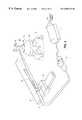
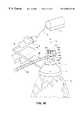
- FIG. 1is a perspective view of a preferred embodiment of the inventive organ manipulation apparatus.
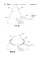
- FIG. 2is a perspective view of another preferred embodiment of the inventive organ manipulation apparatus.
- FIG. 3is a perspective view of another preferred embodiment of suction cup 1 A of FIG. 2 .
- FIG. 4is a cross-sectional view of the FIG. 3 embodiment of cup 1 A.
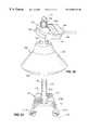
- FIG. 5is a perspective view of a portion of another preferred embodiment of the inventive organ manipulation apparatus.
- FIG. 6is a more detailed perspective view (partially cut away to show element 29 ) of a portion of the FIG. 5 embodiment.
- FIG. 7is a perspective view of a portion of an alternative embodiment of the inventive organ manipulation apparatus.
- FIG. 8is a side cross-sectional view of another preferred embodiment of the inventive suction cup.
- FIG. 9is a perspective view of a portion of another alternative embodiment of the inventive organ manipulation apparatus.
- FIG. 10is a perspective view of a portion of a variation on the FIG. 9 embodiment.
- FIG. 11is a perspective view of a portion of another preferred embodiment of the inventive organ manipulation apparatus.
- FIG. 12is a more detailed perspective view (partially cut away to show element 55 A) of a portion of the FIG. 11 embodiment.
- FIG. 13is a perspective view of a portion of another alternative embodiment of the inventive organ manipulation apparatus.
- FIG. 14is a perspective view of a portion of another alternative embodiment of the inventive organ manipulation apparatus, which employs hinged fingers and multiple suction cups.
- FIG. 15is a perspective view of one finger 72 of the FIG. 14 apparatus gripping the surface of heart 9 , and shows (in phantom view) the position the finger would have if the heart surface were in a lower position.
- FIG. 16is an end view of a portion of one embodiment of the inventive suction cup.
- FIG. 17is a cross-sectional view of the cup portion of FIG. 16, along line 17 — 17 of FIG. 16 .
- FIG. 18is an end view of a seal for use with the cup portion of FIGS. 16 and 17.
- FIG. 19is a side view of the seal of FIG. 18 .
- FIG. 20is a perspective view of the'suction cup and compliant joint of another alternative embodiment of the inventive apparatus.
- FIG. 21is a top view of arm 93 (with pins 96 ) of FIG. 20 .
- FIG. 22is a side elevational view of the suction cup and compliant joint of another alternative embodiment of the inventive apparatus.
- FIG. 23is an end view of a portion of another embodiment of the inventive suction cup.
- FIG. 24is a cross-sectional view of the cup portion of FIG. 23, along line 24 — 24 of FIG. 23 .
- FIG. 25is an enlarged view of a portion of the cup structure shown in FIG. 24, with gauze and a foam seal positioned in the cup.
- FIG. 26is a side cross-sectional view of another embodiment of the inventive suction cup, including gauze and a foam seal positioned in the cup.
- FIG. 27is a perspective view of a portion of an alternative embodiment of the inventive organ manipulation apparatus.
- FIG. 28is a perspective view of another embodiment of the inventive suction member.
- FIG. 29is a perspective view of another embodiment of the inventive suction member.
- FIG. 30is a perspective view of another embodiment of the inventive suction member, with a compliant joint for mounting it to a rigid structure.
- FIG. 31is a side cross-sectional view of another embodiment of the inventive suction member.
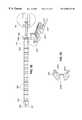
- FIG. 32is a side.elevational view of a preferred flexible locking attachment arm for use in supporting the suction member and compliant joint of the invention.
- FIG. 33is a side.cross-sectional view of one ball joint of the arm of FIG. 32 .
- FIG. 34is a side cross-sectional view of a ball joint of another embodiment of a flexible locking attachment arm for use in supporting the suction member and compliant joint of the invention.
- FIG. 35is a top elevational view of a sleeve of another embodiment of a flexible locking attachment arm for use in supporting the suction member and compliant joint of the invention.
- FIG. 36is a cross-sectional view of the sleeve of FIG. 35, taken along line 36 — 36 of FIG. 35 .
- FIG. 37is a side elevational view of a ball joint for use with the sleeve of FIG. 35 in a flexible locking attachment arm.
- FIG. 38is a side.elevational view of a portion of a flexible locking attachment arm including alternating ball joints (of the type shown in FIG. 37) and sleeves (of the type shown in FIG. 35 ).
- FIG. 39is a perspective view of a portion of a variation on the FIG. 1 apparatus.
- compliant jointis used in a broad sense to denote any mechanical coupling capable of bearing the load-of the inventive suction member (and the organ attached by suction to the suction member) while allowing the suction member (and organ) freedom to move in the described manner.
- the compliant jointcan be implemented in any of a wide variety of ways, including (but not limited to) a sliding ball joint, a hinged joint, a pin which slides in a slot, a universal joint, or a spring assembly in which the spring constant is determined by a bellows, piston, metal spring, or some other compliant element).
- FIG. 1A first preferred embodiment of the invention will be described with reference to FIG. 1 .
- the FIG. 1 embodimentis designed to retract heart 9 (by exerting suction) to a position suitable for performing surgery thereon, and to retain heart 9 in the retracted position (by continued exertion of suction thereon) with limited freedom to move.
- the inventive apparatusincludes the following main elements: suction cup 1 (including conforming seal 2 which extends around the periphery of cup 1 ), ball sliding joint assembly 3 , flexible locking attachment arm 4 (which has both a rigid and a flexible state), suction line 5 , suction flow regulator 6 , and vacuum accumulator 7 .
- the surface of the inventive suction cupe.g., cup 1 of FIG. 1 or cup 1 A of FIG. 2 which contacts the organ to be retracted as the “inner” surface of the suction cup.
- the inner surface of suction cup 1is concave, and is shaped (or can be shaped) so that cup 1 can be attached directly to the apex of heart 9 as shown with seal 2 conforming to the heart surface at the apex, so that cup 1 can lift the heart by exerting suction thereon.
- cup 1is not flexible (except for seal 2 ), but in other preferred embodiments it is flexible.
- cup 1is implemented to be flexible but to have a shape memory, such as by forming the cup of metal mesh (which can resemble chicken wire) coated with a continuous sheet of silicone rubber (and then attaching seal 2 around its periphery).
- the usercan deform the cup (e.g., by pressing it with his or her fingers) to conform the cup to fit against any of a variety of different portions of an organ (or against any of a variety of different organs) and the cup will remain in the selected shape until later deformed by the user.
- conforming seal 2forms a seal with heart 9 (or another organ) while also preventing the organ tissue from being sucked substantially into the internal area of the cup.
- Conforming seal 2is preferably made of biocompatible foam that is glued to the remaining portion of cup 1 .
- seal 2is identical to seal 35 of cup 1 A (to be described below with reference to FIGS. 2, 3 , and 4 ).
- the body of suction cup 1is preferably made of flexible material (e.g., elastomeric material having no shape memory, or a continuous sheet of elastomeric material coated over a deformable metal mesh which has a shape memory), and its inner surface is preferably lined with a soft and absorbent material (not shown in FIG. 1 ).
- the absorbent liningcan be a biocompatible fabric (preferably non-woven rayon/viscose fabric), gauze, or material of the type currently used in neuro-sponges, and is capable of absorbing enough blood and/or other bodily fluid to significantly improve traction between the cup and the organ.
- the absorbent liningalso functions to diffuse the suction.
- the inner surface of cup 1is implemented with compliant cleats protruding out therefrom, or is otherwise textured so as to assist in providing grip on the organ tissue.
- the inner surface of the suction cup(e.g., cup 1 ) is gas-permeable (e.g., porous., or having at least one orifice extending through it).
- the poresare (or the orifice is) in fluid communication with a vacuum source.
- Suctionis provided to suction cup 1 by means of flexible suction line 5 .
- the distal end of line 5is in fluid communication with the pores (or orifice) through the inner surface of cup 1 , and the proximal end of line 5 is in fluid communication with suction flow regulator 6 .
- the suction flow rateis controlled by flow regulator 6 .
- Vacuum accumulator 7is coupled to flow regulator 6 , and serves as a low-pressure reservoir having sufficient volume that it can provide suction in the event of an interruption of regular suction flow from a vacuum source (not shown, but which can be a wall source).
- suction cup 1has a diameter (at its outer periphery) greater than about one inch (25.4 mm), and the vacuum provided by the vacuum source is in the range from ⁇ 7 psi to ⁇ 5 psi ( ⁇ 362 mmHg to ⁇ 258 mmHg).
- the vacuum provided by the vacuum sourceshould be determined (e.g., experimentally) to be as close as possible to atmospheric pressure while still providing enough suction force to reliably grip the organ to be retracted.
- Ball sliding joint 3(which includes ball 3 A and U-shaped element 3 C) connects suction cup 1 to flexible locking attachment arm 4 .
- one end of flexible locking attaching arm 4is attached to sternal retractor 8 (this end can alternatively be attached directly to an operating table) and the other end of arm 4 is attached to ball sliding joint 3 .
- Ball 3 Arides in grooves 3 B of element 3 C.
- Cup 1is mounted rotatably to element 3 C (e.g., by a binding screw which couples them together), so that when element 3 C is oriented with grooves 3 B vertical (as shown in FIG. 1 ), cup 1 can rotate freely about a vertical axis relative to element 3 C.
- joint 3allows cup 1 (and heart 9 ) to rotate about a vertical axis relative to arm 4 and retractor 8 (as ball 3 A rotates relative to element 3 C).
- Joint 3also allows cup 1 (and heart 9 ) limited freedom to translate up and down (along the central longitudinal axis L of cup 1 , which is oriented vertically in FIG. 1) relative to retractor 8 (as vertical grooves 3 B slide up and down relative to ball 3 A) thereby providing compliance to the system.
- As heart 9 beatsits outer surface expands and contracts (which causes, cup 1 and element 3 C to oscillate vertically relative to stationary ball 3 A) and its apex may twist about a vertical axis relative to ball 3 A and arm 4 .
- the FIG. 1 apparatuscan be oriented so that arm 4 does not extend in a horizontal plane (relative to the earth). Regardless of the orientation of arm 4 , when cup l supports an organ, element 3 C will rotate relative to ball 3 A until grooves 3 B are vertical.
- Flexible locking attachment arm 4is designed to have both a flexible-state and a rigid state. In a preferred implementation, this is achieved by implementing free portion 4 B of arm 4 (in a conventional manner) to include a cable running from mount 4 A through a series of ball joints 4 C (or alternating ball joints and sleeves), so that portion 4 B can be changed between a flexible state and a rigid state by tightening (or untightening) the cable using a knob mechanism with a clutch. The clutch guards against overtightening of the assembly, and provides tactile feedback when the maximum tightening is achieved.
- Preferred implementations of ball joints (or ball joints and sleeve) for use in arm 4will be described below, with references to FIGS. 32-38.
- cup 1is placed against the.appropriate portion of heart 9 (for example, on the heart's apex as shown in FIG. 1) either before or after flow regulator 6 is opened, depending on the particular application.
- flexible locking attachment arm 4is manipulated to retract the organ (with cup 1 and ball sliding joint 3 ) into a desired position.
- flexible locking attachment arm 4is moved (e.g., by translating mount portion 4 A along member 8 , and/or placing free portion 4 B in a flexible state and bending free portion 4 B) to manipulate organ 9 into the desired position.
- Ball sliding joint 3permits cup 1 to pivot relative to free portion 4 B of arm 4 (and ball 3 A to translate along grooves 3 B) while the organ is manipulated.
- portion 4 A of arm 4is locked to retractor 8 and portion 4 B of arm 4 is locked into its fixed state, but ball sliding joint 3 is still configured to provide compliance.
- FIG. 2An alternative embodiment of the invention will next be described with reference to FIG. 2 .
- Elements 3 , 5 , 6 , 7 , and 8 of the FIG. 2 embodimentare identical to the identically numbered elements of the above-described FIG. 1 embodiment (and the description thereof will not be repeated).
- Suction cup 1 A of FIG. 2differs slightly from cup 1 of FIG. 1 , in that suction line 5 is coupled (through ball 3 A and element 3 C) to a gas-permeable portion (an orifice or pores) at the center of cup 1 A, whereas suction line 5 is coupled to a gas-permeable portion (orifice or pores) of cup 1 at a location away from the-center of cup 1 .
- rigid arm 10(which replaces flexible locking arm 4 of FIG. 1) exerts a retracting force upon suction cup 1 A.
- Rigid arm 10is preferably adjustably mounted to retractor 8 by a standard tool holder 11 (of a type commonly used in the practice of surgery).
- Rigid arm 10is hollow, and suction line 5 is routed through rigid arm 10 (and then through ball 3 A and element 3 C) to cup 1 .
- cup 1 Ahas a flexible silicone rubber shell 31 with a generally cylindrical attachment portion 32 that defines a central orifice through the shell. Portion 32 is shaped for attachment to the distal end of line 5 .
- the outer periphery of shell 31is a mild ellipse (the ratio of its long axis to and short axis is less than two, e.g., the ratio is about 1.45).
- Absorbent material 33e.g., gauze or “bleed” cloth
- Non-abrasive, organ-contacting (e.g., myocardium-contacting) mesh 34is installed over material 33 to retain the material 33 in the position shown.
- Tapered conformal seal 35(preferably made of biocompatible foam) is glued to the portion of mesh 34 in contact with shell 31 (and to the peripheral portion of shell 31 itself). Specifically, glue 36 is placed on mesh 34 near the periphery of shell 31 (and on shell 31 around its periphery), and foam seal 35 is positioned over glue 36 to glue together the seal 35 , mesh 34 , and shell 31 as shown. Glue 36 should not extend inward to (or beyond) the inner edge of seal 35 , so as to avoid introducing a stiff (hardened glue) surface that would contact the organ during exertion of suction on the organ.
- compliant joint 3(of FIGS. 1 and 2) is replaced by another type of compliant joint, such as one including a pin which slides in a slot, a bellows, a piston, a spring, or some other compliant element.
- rigid arm 24replaces arm 10 (of FIG. 2 ).
- the proximal end of arm 24is attached to sliding mount 28 .
- a second sliding mount 26 attached to arm 24can be translated to a desired location along arm 24 and then locked into place.
- Suction cup 21is attached to the distal end of rigid tube 22 (preferably in such a manner that cup 21 has freedom to rotate about the axis of tube 22 ), and the distal end of compliant element 27 is attached to the proximal end of tube 22 .
- Suction line 25is attached to element 27 in such a manner that line 25 is in fluid communication with the interior of tube 22 , so that a vacuum source can evacuate line 25 and tube 22 and cause cup 21 to exert suction on organ 9 (a human heart) when cup 21 is positioned as shown against heart 9 .
- the proximal end of element 27is attached to sliding mount 26 (so that element 27 and tube 22 have freedom to pivot together as a unit relative to mount 26 ).
- mount 28is translated along a sternal retractor (or operating table) until it is locked at an appropriate position, and mount 26 is loosened (relative to arm 24 ) so that it is free to slide along arm 24 into the desired position (thereby causing the assembly to retract heart 9 coupled to cup 21 into a desired position for surgery).
- mount 26is tightened against arm 24 so that it thereafter remains fixed in the desired position along arm 24 .
- Compliant element 27includes a piston and allows tube 22 limited freedom to translate (parallel to the common axis of tube 22 and element 27 ) relative to arm 24 , for example to accommodate motion of heart 9 as it beats during surgery.
- compliant element 27is replaced by a spring, bellows, or other compliant element or assembly, which allows tube 22 such limited freedom to translate relative to arm 24 .
- element 27is a tube having closed end 28 , with slidable piston 29 mounted in the tube to seal the tube's other end (except that piston 29 allows air to flow from cup 21 's inner surface through tube 22 , piston 29 , and element 27 into suction line 25 ).
- a vacuum sourcedraws air through line 25 , thus evacuating the space within element 27 between end 28 and piston 29 (except for air flowing at a low flow rate from cup 21 through tube 22 into this space).
- heart 9beats, it periodically pulls cup 21 , tube 22 , and piston 29 together as a unit away from end 28 of element 27 , and then relaxes to allow the vacuum source to pull piston 29 back toward end 28 .
- the traction on heart 9is automatic when the vacuum is engaged and cup 21 is attached to the heart.
- the traction and suction cup forceswill remain in a fixed ratio to each other regardless of the strength of the vacuum.
- the ratiois determined by the area of cup 21 (over which cup 21 exerts suction) and the area of piston 29 .
- This parametershould be controlled to ensure that the suction force is only as strong as warranted to retract the heart, in order to avoid trauma to the surface of the heart undergoing suction by the inventive apparatus.
- the traction forceshould never be strong enough to pull cup 21 off the heart (at least directly).
- a vacuum accumulator of sufficient sizee.g., accumulator 7 of FIG. 1 ) it can be assured that the heart is returned gently to its non-retracted position even if the vacuum source is suddenly decoupled from the inventive apparatus.
- straight rod 24is replaced by a curved rod (whose curvature is sufficiently limited to allow mount 26 to slide along it).
- FIG. 5Another variation on the FIG. 5 embodiment will be described with reference to FIGS. 11 and 12.
- straight rod 24is replaced by rigid member 54 (which is fixedly attached to mount 28 ), long, threaded bolt 55 having one end mounted to member 54 (with freedom to rotate but not translate relative to member 54 ), and crank 57 attached to the other end of bolt 55 .
- Bolt 55can be rotated relative to member 54 by turning crank 57 (with non-threaded portion 55 A of bolt 55 rotating in a non-threaded orifice in member 54 ).
- Mount 26(of FIG. 5) is replaced by threaded mounting member 56 whose threads mate with those of bolt 55 .
- threaded mounting member 56can be advanced along bolt 55 (together with compliant element 27 and suction cup 21 attached to member 56 ) by turning crank 57 .
- suction cup 41is attached by cable 42 to hollow, flexible locking attachment arm 46 (which has both a flexible state and a rigid state).
- the other end of cable 42is attached to rod 48 of a piston (not shown) within compliant element 49 .
- Mount 43is slidably mounted relative to sternal retractor 8
- arm 46is rotatably mounted to mount 43
- chamber 49is fixedly mounted to mount 43 .
- mount 43After mount 43 has been moved into a desired position relative to sternal retractor 8 , it can be locked to mount 43 .
- Arm 46can be rotated relative to mount 43 and locked into a desired rotational position relative to mount 43 .
- Arm 46(like arm 4 of FIG.
- cup 41can be positioned as desired relative to retractor 8 .
- the FIG. 7 apparatusprovides cup 41 freedom to swing (on cable 42 ) relative to arm 46 and is it provides cup 41 limited freedom to move vertically relative to retractor 8 .
- Compliant element 49includes a piston (not shown) which is coupled to rod 48 to allow rod 48 limited freedom to translate (parallel to the common axis of rod 48 and element 49 ) relative to mount 43 , for example to accommodate motion of a heart (supported by cup 41 ) as the heart beats during surgery.
- element 49encloses a volume between closed end 49 A and a slidable piston.
- the pistonis fixedly attached to rod 48 .
- Suction line 50is connected to element 49 (in fluid communication with the volume enclosed by element 49 ) so that a vacuum source can draw air through line 50 from such enclosed volume.
- the same vacuum sourceis coupled to suction cup 41 via suction line 45 . Lines 45 and 50 are both coupled by line 51 to the vacuum source.
- the inner surface of arm 46is lined with Teflon material or the like (or includes bearings made of such material) to reduce friction on cable 42 .
- suction cup 41can be implemented to be rigid. (e.g., it is composed of Delrin, ABS, Ultem, or polycarbonate plastic, or other hard plastic, with its inner surface lined with absorbent material), and has seal 41 A attached (e.g., by glue, which can be Silastic Medical Adhesive Silicone Type A, available from Dow Corning, when the cup is made of Delrin plastic) around its periphery.
- Seal 41 Acan be a biocompatible foam seal as in cup 1 A of FIGS. 3 and 4 ).
- Cup 41has a shape which conforms to a target portion of a typical organ of the type to be retracted using the cup, and its inner (concave) surface is preferably smooth and lined with absorbent material to improve traction.
- Adhesives suitable for use with plastic or silicone components of various embodiments of the inventioninclude Silastic Medical Adhesive (available from Dow Corning), and Loctite 4541 or Loctite 4011 adhesive.
- the suction cup of the inventionis implemented to be flexible but to have a shape memory.
- Suction cup 1 B of FIG. 8is made of metal mesh 40 (which can resemble chicken wire) coated on both sides with a continuous sheet 39 of flexible silicone rubber (or other flexible, biocompatible material).
- metal mesh 40which can resemble chicken wire
- silicone rubberor other flexible, biocompatible material
- Generally cylindrical attachment portion 38defines a central orifice through the otherwise continuous sheet 39 .
- Portion 38is shaped for attachment to the distal end of a suction line.
- Tapered conformal seal 35(preferably made of biocompatible foam) is glued to the peripheral portion of sheet 39 .
- cup 1 B of FIG. 8is placed over the organ (with seal 35 against the organ surface) and mesh 40 is deformed (by the user's fingers) to conform with the organ surface. Mesh 40 will retain the cup in its final shape after the user has finished shaping the cup. Then, a vacuum source is coupled to the cup to draw air through the orifice through attachment portion 38 . This evacuates the region bounded by the cup's inner surface, seal 35 , and the organ, and causes cup 1 B to exert suction on the organ.
- the inventive suction cupis implemented to be rigid (e.g., it is composed of hard plastic with its inner surface lined with absorbent material), and has a seal around its periphery (e.g., a biocompatible foam seal).
- the cuphas a shape which conforms to a target portion of a typical organ of the type to be retracted using the cup.
- the inner surface of the cupis preferably smooth, and lined with absorbent material to improve traction.
- An example of such a rigid cupis cup 41 of FIG. 7 .
- cup portion 81is machined from rigid Delrin plastic, and seal 82 is made of biocompatible foam.
- the end surface of cup portion 81has a central orifice 83 extending therethrough.
- tapered surface 85 of seal 82is glued to tapered inner surface 84 of portion 81 at the periphery of portion 81 (e.g., with Silastic Medical Adhesive Silicone Type A, available from Dow Corning).
- a threaded pipe-shaped memberis attached (e.g., using nuts and a washer) to the end surface of portion 81 (so as to extend through orifice 83 ), and a suction tube is then placed through the pipe-shaped member into fluid communication with inner surface 84 of portion 81 .
- the pipe-shaped membercan be screwed onto a threaded portion of the joint (or the pipe-shaped member can be otherwise attached to the joint).
- Steel wool(or another substance) can be packed loosely in the cylindrical bottom of portion 81 to prevent loss of fluid communication between the cup's inner surface 84 and the suction line, and the inner surface 84 of portion 81 can be lined with absorbent material.
- FIG. 20includes suction cup 91 (which has a circular periphery and includes seal 92 which extends around cup 91 's periphery to provide a vacuum seal when the cup placed in contact with an organ), suction line 97 (which is coupled to a vacuum source to evacuate the volume inside cup 91 when the cup is positioned in contact with an organ), and a compliant joint including element 94 (having parallel slots 95 in .opposing portions of its side wall) and arm 93 having pins 96 which ride in slots 95 . Both slots 95 (only one of which is shown in FIG. 20) are oriented parallel to the central longitudinal axis of cup 91 .
- Pins 96 and the distal portion of arm 93are better shown in FIG. 21 .
- arm 93can support element 94 , cup 91 , and an organ suspended (by suction) from cup 91 .
- element 94can pivot (about pins 96 ) relative to arm 93 , gravity will ensure that slots 95 (and the central longitudinal axis of cup 91 ) will remain generally vertical during organ retraction (although they will not necessarily remain fully vertical). Since slots 95 are substantially longer than the diameter of each pin 96 , the assembly comprising element 94 and cup 91 is free to slide vertically relative to pins 96 during organ retraction.
- each slot 95is sufficiently long to allow vertical oscillation of cup 91 with an amplitude up to about 0.5 inch.
- FIG. 22Another embodiment of the invention, to be described with reference to FIG. 22, is designed to minimize the overall vertical size of the suction cup and compliant joint assembly.
- the FIG. 22 embodimentcomprises suction cup 101 (which has a circular periphery and a seal portion which extends around the periphery), suction line 107 (which is coupled to a vacuum source to evacuate the volume inside cup 101 when the cup is positioned with the seal portion in contact with an organ), and a compliant joint (including elements 102 , 103 , and 104 ) for attaching rigid arm 104 to the rest of the FIG. 22 apparatus.
- Two pins 105are fixedly attached to cup 101 in the positions shown.
- Element 102has parallel slots 108 in its left and right side portions, and one of the pins 105 rides in each of the slots 108 .
- Member 103is rotatably attached to element 102 (e.g., by a binding screw) in such a.manner that element 102 is free to rotate about a vertical axis relative to member 103 .
- Member 103is mounted to rod 104 with freedom for member 103 to swing about the axis of rod 104 .
- arm 104supports element 102 and member 103
- element 102in turn supports cup 101 and an organ suspended (by suction) from cup 101 .
- FIGS. 23-25Another example of the suction cup of the invention, designed to have low profile, will be described with reference to FIGS. 23-25.
- the cuphas a truncated conical profile, with annular end surface 112 (having central orifice 113 extending therethrough) at one end, and circular periphery 110 at the other end. Orifice 113 is for attaching the cup to a compliant joint.
- Suction orifice 111extends through the conical side wall of the cup (for connecting a suction line to the cup), and gauze can be packed into the volume surrounded by cylindrical surface 115 (FIG. 25 shows gauze 120 so packed).
- Foam seal 121(partially shown in FIG.
- the cup 25can be glued.to flat annular surface 116 and the conical side wall portion between surface 116 and periphery 110 .
- the conical side wallis oriented at an angle of 35 degrees with respect to the cup's central longitudinal axis L.
- the cuphas a height of 0.95 inch (from end 112 to the plane of periphery 110 ), the center of orifice is 0.56 inch from the plane of periphery 110 , the diameter of cylindrical surface 115 is 0.75 inch, and periphery 110 has a diameter of 1.95 inches.
- the cup of FIGS. 23 and 24can be machined from ABS material or rigid plastic (e.g., Delrin material).
- the angle of the conical side wall(relative to the central longitudinal axis L) is varied to vary the diameter of periphery 110 .
- this anglecan be 28 degrees (rather than 35 degrees as in FIG. 24) to give periphery 110 a diameter of 1 . 64 inches, or 21 degrees (rather than 35 degrees) to give periphery 110 a diameter of 1.35 inches.
- Decreasing the angle between the conical side wall and the central longitudinal axis Ldecreases the diameter of periphery 110 .
- the minimum useful diameter of periphery 110will typically be about 1.35 inches (where the cup is to be affixed to the apex of a heart), although it may be as low as about 1 inch for some applications.
- FIG. 25when gauze 120 is packed into the volume surrounded by cylindrical surface 115 (of the cup of FIG. 24) and foam seal 121 is mounted in its proper position, there may be a gap between the seal and gauze at the right-angled intersection of surface 115 with surface 116 . Under certain operating conditions, exposure of the heart tissue to such gap (during application of suction to the heart) may result in irritation to the heart tissue and/or sucking of an excessive amount of heart tissue into the cup.
- the FIG. 26 embodimentis designed to reduce or eliminate this potential problem. Note also that the bottom of the cup can be equipped with ribs (rib members) to prevent fabric and tissue from being sucked up into the suction tube orifice of the apparatus.
- FIG. 26 embodimentis shaped slightly differently than that of FIGS. 23-25. More specifically, the FIG. 26 embodiment differs from that of FIGS. 23-25 in that tapered (frusto-conical) surface 125 replaces cylindrical surface 115 of FIGS. 24-25, and in that flat annular surface 126 replaces surface 116 .
- Components of the FIG. 26 embodiment that are identical to those of FIGS. 23-25are identically numbered in FIGS. 23-26. Due to the geometry of the FIG. 26 embodiment, when gauze 120 is packed into the volume surrounded by surface 125 and foam seal 121 is mounted in its proper position, there is a smooth, continuous transition between the seal and gauze at the intersection of surface 125 with surface 126 .
- the inventive cuppreferably has a generally hemispherical (or concave elliptical) shape with a circular (or mild elliptical) periphery, so that it conforms to the apex of the heart. Cups having less curvature (flatter cups) and/or rectangular periphery have been found to be less suitable for heart retraction since they must be affixed to relatively flatter surfaces of the heart (not to the apex) and have a greater tendency to decouple from the heart after being affixed. However, such alternative cup embodiments may be useful for retracting or otherwise manipulating organs other than the heart.
- the inventive suction memberis effectively custom-fitted to the organ to be supported and manipulated.
- One way to accomplish such.custom-fittingis to implement the suction member as a pellet-filled flexible body which is impervious to fluid flow (except in that it has a gas permeable inner surface which allows a vacuum source to pull a vacuum on a portion of an organ facing the suction member).
- An example of such a suction memberis a beanbag-like body comprising a flexible plastic enclosure filled with small pellets (which can be beads).
- the bodyis placed against the appropriate part of organ and air (or other gas) within the body is then evacuated so that the pellets remaining in the evacuated body form a rigid structure which conforms to the relevant surface of the organ. Since the inner surface (which contacts the organ) of the pellet-filled body is permeable to gas, the vacuum source causes the member to exert a suction force on the organ while also maintaining the member in its rigid state.
- the suction memberwhich comprises a rigidizing bag containing pellets (which can be beads).
- the suction membercomprises elastomeric beads 12 (which can be injection molding stock), contained in rigidizing bag 11 .
- One face of bag 11is attached by a compliant joint 13 to the distal end of rigid tube 14 (with an orifice in such face of the bag in fluid communication with the tube's interior).
- the proximal end of tube 14is coupled to a vacuum source so that pulling a vacuum on tube 14 evacuates bag 11 thereby rigidizing it.
- the inner surface of bag 11is permeable to gas (e.g., it is porous or has at least one small orifice extending through it) so that the vacuum source will also cause the suction member to exert suction on an organ in contact with the member's inner surface.
- the suction membercomprises a rigid central portion 18 (having concave inner surface, and preferably made of hard plastic lined with soft absorbent fabric or other absorbent material) and a rigidizing bag 19 (containing elastomeric beads) which extends around the periphery of central portion 18 .
- Compliant joint 13is coupled between the distal end of rigid tube 14 and central portion 18 .
- the interior of tube 14is in fluid communication with the interior of bag 19 , so that pulling a vacuum on tube 14 evacuates bag 19 thereby rigidizing it.
- portion 18is permeable to gas (e.g., it is porous or has at least one small orifice extending through it to tube 14 ) so that the vacuum source will also cause the suction member to exert suction on an organ in contact with the member's inner surface.
- the suction member of the inventive apparatusis implemented with a smooth inner surface (e.g., a smooth biocompatible foam seal around the periphery and a smooth fabric surface between the center and periphery) to provide traction (e.g., by absorbing blood which would otherwise cause the member to slip from the organ) while avoiding trauma to the organ (e.g., bruising) during retraction.
- a smooth inner surfacee.g., a smooth biocompatible foam seal around the periphery and a smooth fabric surface between the center and periphery
- tractione.g., by absorbing blood which would otherwise cause the member to slip from the organ
- trauma to the organe.g., bruising
- the inner surface of the suction membermay be somewhat rough (e.g., with bumps or the like protruding therefrom) or textured to improve traction between the suction member and organ.
- the suction member of the inventione.g., suction cup 61 shown in FIG. 13
- the suction member of the inventioncan be made of flexible plastic film (e.g., film 62 of cup 61 ) with its inner surface lined with absorbent material (e.g., felt or felt-like material), and with a hyper-extensible elastomeric seal (e.g., seal 63 of cup 61 ) around its periphery.
- absorbent materiale.g., felt or felt-like material
- a hyper-extensible elastomeric seale.g., seal 63 of cup 61
- the suction member of the inventioncan be connected to a constant force spring arrangement which applies a constant retraction force to the suction member, while still providing rotational and translational compliance.
- suction cup 61is attached to the distal end of cable 64 .
- Support assembly 65includes low tension, constant force spring 66 .
- the proximal end of cable 64is attached to spring 66 .
- Support assembly 65is designed to be adjustably mounted (preferably with a low profile) to a sternal retractor or other fixed structure.
- Assembly 65 and cable 64support cup 61 (and the organ held by suction to cup 61 ) with a constant force, while allowing cup 61 freedom to swing and rotate relative to assembly 65 and to undergo vertical oscillation relative to assembly 65 (e.g., in response to beating motion of a beating heart).
- a constant force spring arrangement which applies a constant retraction force to a suction cupcan also be used in a variation on the above-described FIG. 1 embodiment.
- the constant force spring arrangementis coupled between suction cup 1 and the distal end of portion 4 B of attachment arm 4 (in place of sliding ball joint 3 ).
- the springis configured to apply a constant retraction force to suction cup 1 , while still providing rotational and translational compliance by allowing the cup to rotate relative to arm 4 and to undergo vertical oscillation relative to arm 4 .
- a set of one or more springsis employed to apply a retraction force (which can but need not be a constant force) to the suction cup of FIG. 1 or any of the other embodiments of the invention.
- the set of springsis coupled between the suction cup (e.g., cup 1 ) and the distal end of the arm which supports it (e.g., attachment arm 4 ). The set of springs allows the cup to vertical oscillation relative to arm 4 .
- the set of springsis rotatably mounted to the cup (e.g., by being attached between the support arm and a plate, where the plate is rotatably mounted to the cup) so that the cup is free to rotate about a vertical axis relative to the support arm, as well as to undergo vertical oscillation relative to the support arm.
- the compliant joint of the inventionis implemented as a universal joint, or a set of two or more universal joints.
- An aspect of the inventionis a preferred method for retracting a beating heart in which a suction member (implemented in accordance with any embodiment of the inventive apparatus) is affixed to a heart at a position concentric with the apex of the heart.
- a suction member(implemented in accordance with any embodiment of the inventive apparatus) is affixed to a heart at a position concentric with the apex of the heart.
- the suction memberhas sufficient curvature to conform with the apex and is shaped to be at least generally symmetric with the apex.
- Suctionis applied to the heart by coupling the suction member to a vacuum source, and the suction member is moved to retract the heart to a desired position for surgery.
- the suction memberis mounted to a fixed assembly (e.g., a fixedly mounted sternal retractor) by a compliant joint so that the suction member does not constrain normal beating motion of the heart during gross movement of the suction member and heart into the desired position, and while the suction member supports the heart (e.g., while the heart is suspended vertically below the member) in such position.
- a fixed assemblye.g., a fixedly mounted sternal retractor
- the suction membersupports the heart (e.g., while the heart is suspended vertically below the member) in such position.
- the suction memberhas an axis of symmetry, and as the heart beats, the heart is free to expand and contract, with the compliant joint allowing the suction member to oscillate along the axis of the suction member (e.g., along a vertical axis) and to twist about the axis (e.g., the vertical axis) relative to the fixed assembly, so that hemodynamic function is not compromised.
- Another aspect of the inventionis a method including the steps of:
- an arme.g., arm 4 of FIG. 1 or arm 10 of FIG. 2 which supports the suction cup (e.g., by sliding arm 1 . 0 relative to holder 11 , and/or sliding holder 11 relative to element 8 ) to achieve the desired amount of retraction;
- the inventive method and apparatusallows manipulation of a beating human heart so as to expose lateral or posterior coronary arteries for the purpose of bypassing those vessels.
- the inventive, apparatusdoes not rigidly constrain the heart muscle, the invention allows the heart anatomy to retain its natural shape and performance.
- the compliance provided by the apparatusis intended to replicate the motion allowed when the heart is manipulated either directly by the human hand or by pulling the pericardium.
- inventionsare methods and apparatus for cardiac retraction during beating heart surgery
- other embodimentsare methods and apparatus for retracting almost all other internal organs.
- the size, shape, and material of the suction cup employed as well as the amount of vacuum appliedcan be varied to match the topology and consistency of the organ tissue. More than one suction cup at a time can be applied to each organ, to provide greater or more stable manipulation. Multiple cups can be mounted to a single support structure (with one or more compliant joints providing compliance between each cup and the support structure), and the cups can then be affixed to the organ in such a way as to retract the organ in a desired direction without interfering with the natural movement of the organ. Affixing of multiple suction cups to an organ would allow torsion to be applied to the organ. Organs often must be twisted or rotated for better tissue presentation preliminary to surgery.
- the fingersare mounted on a compliant joint which is in turn supported by a fixed structure (or the fingers themselves have compliance and function as a compliant joint), so that the fingers do not constrain normal beating motion of the heart (or normal motion of the other organ) during gross movement of the fingers and organ into the desired position or during surgery on the organ held by the fingers.
- finger assembly 71includes three suction cups 75 and three hinged fingers 72 .
- Each cup 75is mounted at the distal end of one of the fingers.
- Each finger 72has a hinge 73 (which is coupled to extension member 76 ) and another hinge 73 A, and member 76 is adjustably coupled to a sternal retractor (not shown) or other fixed structure.
- Extension member 76is coupled to hinges 73 in such a manner that a user can manipulate member 76 to cause hinges 73 to spread fingers 72 (before assembly 71 grips a beating heart or other organ) and then to cause hinges 73 to gather fingers 72 until cups 75 grip the organ (as shown in FIG. 14 ).
- a vacuum sourcecoupled to cups 75 (via suction lines extending through fingers 72 and member 76 ) is actuated to provide suction force on the organ.
- Member 76can then be moved to retract the organ into a desired position for surgery.
- Assembly 71functions as a compliant joint, in addition to functioning as a set of suction cups, since while assembly 71 grips the organ, hinges 73 and 73 A allow fingers 72 to flex in response to normal movement of the organ (e.g., in response to beating movement of a beating heart). For example, as shown in FIG. 15, when the surface of heart 9 moves upward (from the lower position shown in phantom view) to the raised position shown by the solid line, hinges 73 and 73 A pivot to allow finger 72 to move (from the relatively more flexed position shown in phantom view) to the relatively less flexed position shown by the solid lines.
- fingers 72This compliance provided by the flexing action of fingers 72 allows cups 72 to oscillate in parallel to the axis of member 76 as the heart beats.
- fingers 72are coupled to extension member 76 in such a manner that assembly 71 has freedom also to rotate about the axis of member 76 (while member 76 remains fixed).
- embodiments including finger assembliesare variations (on any of the “single suction cup” embodiments described herein which include a single suction cup) in which a retracting finger assembly replaces the single suction cup.
- the retracting finger assemblydoes not include a suction cup at the end of each finger, and instead each finger has a non-slip surface at its distal end so that an organ (e.g., a beating heart) can be gripped by the non-slip surfaces.
- FIG. 28is a perspective view of another embodiment of the inventive suction member, which is a variation on suction;cup 61 of FIG. 13 .
- Suction member 130 of FIG. 28comprises flexible bag-like membrane 131 (which can be made of plastic film and preferably has its inner surface lined with absorbent material), and ring 132 around the periphery of membrane 131 .
- Ring 132is preferably made of plastic or silicone, and its inner face supports sealing material (e.g., elastomeric material) which faces the heart and is capable of forming a seal around the periphery of member 130 .
- sealing materiale.g., elastomeric material
- Suction line 133is coupled to ring 132 , with its distal end sealed around an orifice extending through ring 132 so as to be in fluid communication with the inner surface of membrane 131 .
- Suction member 140 of FIG. 29is a variation on that of FIG. 28 .
- Suction member 140 of FIG. 29comprises flexible bag-like membrane 141 (which can be made of plastic film and preferably has its inner surface lined with absorbent material), and ring 142 around the periphery of membrane 141 .
- Ring 142(which is narrower than relatively wide ring 132 ) is preferably made of plastic or silicone, and its inner face supports sealing material which faces the heart and is capable of forming a seal around the periphery of member 140 .
- Suction line 143is coupled to ring 142 , with its distal end sealed around an orifice extending through ring 142 so as to be in fluid communication with the inner surface of membrane 141 .
- FIG. 13, FIG. 28, and FIG. 29 embodiments of the inventionhas several advantages including the following the design helps maintain the natural shape of the beating heart at all times to maintain hemodynamic function; and placement of the suction member at any of various places on the heart (e.g., on the apex, right ventricle, or AV groove) does not detract from or interfere with the mechanical or electrical function of the beating heart.
- FIG. 30is a perspective view of another embodiment of the inventive suction member, with a compliant joint for mounting it to a rigid structure.
- Suction member 150 of FIG. 30includes a cup 151 , a hollow shaft 153 fixedly attached to cup 151 , and fitting 157 (for attaching a suction line to shaft 153 ).
- Shaft 153is oriented with its axis parallel to the central longitudinal axis of cup 151 .
- Conforming seal 152(which performs the same function as does above-described seal 35 ) is mounted to the distal surface of cup 151 .
- Seal 152forms a seal with the heart (or other organ) while preventing the organ tissue from being sucked substantially into the internal area of cup 151 .
- the concave inner surface of cup 151(not shown in FIG. 30) is preferably lined with soft and absorbent material (preferably non-woven rayon or viscose fabric, but alternatively another material such as gauze or a material of a type currently used in neuro-sponges).
- the absorbent materialis preferably capable of absorbing enough blood and/or other bodily fluid to significantly improve traction between the cup and organ, and preferably also functions to diffuse the suction exerted by member 150 on the organ.
- Conforming seal 152is preferably made of biocompatible foam having open cells (to allow slow flow of air through seal 152 ), except in that is has closed cells (which define a “skin”) on the distal surface of seal 152 (the surface designed to contact the organ).
- compliant joint 154 attached to the distal end of arm 159comprises ball 164 , socket member. 165 , and ball connector 166 .
- Connector 166is fixedly attached to the distal end of arm 159 .
- Arm 159(which can be a locking attachment arm having a flexible state as well a rigid state) has a distal end which is fixedly mounted to a rigid structure (e.g., a sternal retractor).
- Socket member 165is attached to connector 166 with freedom to rotate relative to connector 166 about the axis of the distal portion of arm 159 .
- Ball 164is attached to member 165 with freedom to rotate relative to member 165 .
- Ball 164defines a central channel, and shaft 153 of suction member 150 extends through this channel (as shown).
- spring 156is positioned around shaft 153 between fitting 157 and ball 164 .
- spring 156is omitted.
- FIG. 30 assemblyfunctions as follows.
- the weight of the heartcauses shaft 153 (and the entire cup 150 ) and ball 164 to rotate as a unit (relative to member 165 ) so that shaft 153 is oriented vertically.
- member 165typically also rotates relative to fixed ball connector 166 .
- the deviceis implemented so that rotation of member 165 relative to connector 166 occurs only during gross manipulation of the suction member (with the heart coupled by suction to the suction member).
- shaft 153As the vertically oriented shaft 153 oscillates vertically as a unit with the surface of the beating heart, shaft 153 slides (through ball 164 's central channel) relative to ball 164 (while the vertical position of ball 164 is fixed by socket member 165 .
- Spring 156damps the oscillating motion of shaft 153 relative to ball 164 , in the following manner. As shaft 153 slides vertically downward relative to ball 164 , spring 156 is compressed (converting some of the kinetic energy of shaft 153 into potential energy). Then, as shaft 153 slides vertically upward relative to ball 164 , spring 156 relaxes (elongates) back to its equilibrium position (assisting in pulling the heart surface upward as some of the potential energy stored in the spring is converted to kinetic energy of shaft 153 ).
- socket member 165includes a pivoting latch 165 A which can be manually rotated between two positions a first position (shown in FIG. 30) in which it does not prevent shaft 153 from translating relative to ball 164 ; and a second (locking) position in which it prevents translation of shaft 153 relative to ball 164 .
- the pivot about which latch 165 A rotatesis attached to member 165 , and thus latch 165 A is fixed relative to arm 159 except in that it is free to rotate (as a unit with member 165 ) about the axis of arm 159 's distal end.
- latch 165 AWhen latch 165 A is rotated into the locking position, its free end hooks onto (or is wedged against) fitting 157 so as to prevent translation of shaft 153 relative to ball 164 .
- a latche.g., latch 165 A
- a locking positionto constrain heart movement temporarily, such as if the surgeon is having difficulty in executing a graft.
- Alternative embodiments of the inventioninclude a latch (or other simple locking structure) other than latch 165 A.
- Each such locking structurecan be moved between two positions a first position in which it allows shaft 153 freedom to translate relative to ball 164 (or more generally, in which it allows the suction member freedom to translate along the suction member's central axis relative to the fixed structure to which the suction member is mounted); and a second (locking) position in which it prevents relative motion of shaft 153 relative to ball 164 (or more generally, in which it prevents relative motion of the suction member relative to the fixed structure to which the suction member is mounted).
- a latchin its locking position
- the latch (in its locking position)extends between member 165 (or an alternative socket member implementation) and cup 151 .
- FIG. 31is a cross-sectional view of another embodiment of the inventive suction member.
- Suction member 170 of FIG. 31has a cup portion comprising a rigid core 172 (preferably made of rigid plastic) and a flexible cup 171 (preferably made of silicone molded over core 172 ).
- Rigid core 172has a shaft portion through which orifice 176 extends, and projections 172 A and 172 B which extend radially out from the shaft portion.
- the shaft portion of core 172is to be mounted through ball 164 of compliant joint 154 (or to another embodiment of the compliant joint of the invention), and a vacuum fitting (e.g., fitting 157 of FIG.
- cup 170is typically mounted at the upper end of the shaft (so that cup 170 is free to translate relative to the ball of the compliant joint, with the constraint that the ball stops the vacuum fitting at one end of the cup's range of motion and the ball stops upper surface 178 of cup 170 at the other end of the cup's range of motion).
- Silicone cup 171can be molded over core 172 (which can but need not be formed of plastic), so that core 172 provides axial support for cup 171 and so that the shaft portion of core 172 can be attached to a compliant joint (thereby attaching cup 171 to the compliant joint without interfering with the function of flexible flange portion 171 A of cup 171 ).
- Conforming seal 175(which performs the same function as does above-described seal 35 ) is mounted to the distal surface of flange 171 A.
- Flange portion 171 A of cup 171provides compliance, allowing seal 175 to move in the axial direction (the vertical direction in FIG.
- seal 175can conform to organ surfaces having any of a wide range of sizes and shapes.
- Seal 175conforms to and forms a seal with the heart (or other organ) while preventing the organ tissue from being sucked substantially into the internal area of the cup.
- the concave inner surface of cup 171is preferably lined with soft and absorbent material 174 .
- Material 174is preferably non-woven rayon or viscose fabric, but can alternatively be another material (such as material of a type currently used in neuro-sponges). Material 174 is preferably capable of absorbing enough blood and/or other bodily fluid to significantly improve traction between the cup and organ, and preferably also functions to diffuse the suction exerted by member 170 on the organ.,
- Conforming seal 175is preferably made of biocompatible foam having open cells (to allow slow flow of air through seal 175 ), except in that is has closed cells (which define a “skin”) on the distal surface of seal 175 (the surface designed to contact the organ).
- the surface area which faces the organis in the range 0.6-1.5 inch 2
- the vacuum provided by the vacuum sourceis in the range ⁇ 65 mm Hg to ⁇ 400 mm Hg (preferably ⁇ 250 mm Hg to 350 mm Hg.
- the vacuum provided by the vacuum sourceis equal (or substantially equal) to ⁇ 300 mm Hg.
- the arm of FIG. 32includes a distal joint 202 , a number of ball joints 203 , a housing 205 (whose distal surface abuts the ball joint 203 farthest from joint 202 ), and a flexible cable 200 strung through elements 202 , 203 , and 205 .
- Cable 200has cylinder 201 fixedly attached at its distal end.
- a conventional cable length control mechanismcomprising housing 205 , knob 204 , pin 206 , and a bar clamp assembly which comprises base 207 , foot 208 , lever 209 , and cam 210 (between lever 209 and foot 208 ), is employed to control the amount of slack in cable 200 between distal joint 202 and the distal end of housing 205 .
- the clamp assembly and knob 204are manipulated to introduce slack in cable 200 , the ball joints 203 have freedom to slide and rotate relative to each other (and thus the arm has freedom to bend into a desired configuration).
- the clamp assembly and knob 204are again manipulated to shorten the length of cable 200 between joint 202 and the distal end of housing 205 .
- Such shortening of the effective length of the cablecauses ball 200 to move joint 202 toward housing 205 , thereby squeezing ball joints 203 between joint 202 and housing 205 so as to fix the ball joints 203 in their desired relative positions (which in turn keeps the arm fixed in a rigid state having the desired configuration).
- Conventional ball jointsare made of stainless steel, and have roughly the same shape as ball joint 203 shown in FIG. 33 .
- This shapeincludes a convex “ball” surface (at the left side of FIG. 33) and a concave “socket” surface (at the right side of FIG. 33 ).
- the socket surface of each ball jointis pressed against the ball surface of the ball joint immediately distal thereto, when the ball joints are tightened together to put the arm in its rigid state.
- the shape of conventional ball jointsdoes not provide good mechanical advantage when the ball joints are tightened together to put the arm in the rigid state.
- the surface composition (and smooth texture) of conventional ball jointsprovides very little friction to assist with locking the arm when the ball joints are tightened together.
- Ball joint 203 of FIG. 33embodies this improved design.
- Ball joint 203 of FIG. 33has shortened length and increased diameter relative to conventional ball joints.
- ball joint 203 's diameter(from top to bottom in FIG. 33) is greater than ball joint 203 's length (from left to right in FIG. 33 ).
- the lengthis 0.345 inch and the diameter is 0.460 inch in a preferred embodiment (or more generally, the ratio of the length to the diameter is at least substantially equal to 0.345/0.460).
- the shape of the socket surfaceis modified (to be as shown in FIG.
- Central hole 203 B through each ball jointis angled (or tapered) to allow the cable to pass through it smoothly and easily (and to improve rigidity in the rigid state, since cable length with the improved ball joint design will not change as much as with the conventional ball joint design during each transition from the flexible to the rigid state).
- the main portion of the ball jointis molded from hard plastic, such as polycarbonate plastic, Ultem (polyetherimide) plastic, or SST material.
- a portion 203 A of the socket surfaceis coated with material having greater friction (such as a thermoplastic or silicone elastomer).
- This coating of portion 203 Acan be accomplished by injection molding the thermoplastic or silicone elastomer into a groove (at the location of portion 203 A) in the socket surface of the hard plastic molding.
- portion 203 Ais an annular (O-ring shaped) region comprising thermoplastic or silicone elastomer material having Shore A durometer in the range 50 to 90.
- socket surface of the ball jointis coated with thermoplastic or silicone elastomer (or other relatively high friction material).
- all or part of the socket surface of each ball jointi.e., the part of each concave socket which mates with an adjacent convex ball surface
- is molded with a rough texturewhich provides sufficiently high friction to adequately lock the arm when a convex ball surface of an adjacent ball joint is tightened against the portion having rough texture.
- An example of the latter embodimentis a variation on ball joint 203 of FIG. 33 which is molded from hard plastic with a smooth (non-textured) outer surface, except that portion 203 A of its concave socket surface is molded with a rough texture.
- adjacent pairs of the ball joints 203are made from materials having different hardness (so that the harder material wedges into the softer material).
- the even (or odd) ball jointsare molded from polycarbonate plastic, and the odd (even) ball joints are molded from Ultem plastic.
- ball joint 303 of FIG. 34replaces each ball joint 203 of FIG. 32 .
- Ball joint 303differs from ball joint 203 in that socket surface 304 of ball joint 303 has a jagged profile, comprising circular shoulders 305 .
- Shoulders 305are designed to bite into the convex ball surface of the adjacent ball joint 303 , thus increasing friction between the convex ball surface and the socket surface 304 in contact therewith, to assist with locking the arm when the ball joints are tightened together.
- Annular (O-ring shaped) portion 303 A of ball joint 303is optionally made of material which (when in contact with the convex ball surface of an adjacent ball joint) provides greater friction than if portion 303 A were made of the same hard plastic material (e.g., polycarbonate or Ultem plastic, or SST material) as is the rest of ball joint 303 .
- region 303 Acomprises thermoplastic or silicone elastomer material having Shore A durometer in the range 50 to 90 (which is molded into a recess in the remaining portion of ball joint 303 ).
- FIG. 35is a top elevational view of sleeve 340
- FIG. 36is a cross-sectional view of sleeve 340 taken along line 36 — 36 of FIG. 35
- FIG. 37is a side elevational view of ball joint 350 .
- Central channel 341 through sleeve 340is tapered at both ends (as shown) to allow a cable to pass through it smoothly and easily (and to improve rigidity in the arm's rigid state).
- the wall of channel 341defines a socket surface at each end of channel 341 , with each socket surface having a jagged profile comprising circular shoulders 342 and 343 and indentations 344 (shown in phantom view in FIG. 36 ).
- shoulders 342 and 343 and the edges of indentations 344are designed to bite into a convex ball surface of an adjacent ball joint 350 , thus increasing friction between the convex ball surface and the sleeve 340 in contact therewith, to assist with locking the arm when the sleeves and ball joints are tightened together.
- Ball joint 350has an annular flange 352 around its periphery, for limiting the freedom of an adjacent sleeve 340 to slide over the outer surface of ball joint 350 .
- Ball joints 350 and sleeves 340are shaped so as to fit together as shown in FIG. 38, with a cable (not shown) extending through their aligned central channels 341 and 351 . In some implementations of FIG.
- each ball jointis made from a hard plastic having a first hardness and each sleeve is made from a hard plastic having a second hardness (different from the first hardness) so that the harder material wedges into the softer material.
- the S ball jointscan be molded from polycarbonate plastic and the sleeves from Ultem plastic (or the sleeves can be molded from polycarbonate plastic and the ball joints from Ultem plastic).
- the ball joints (or ball joints and sleeves) used in the locking arm employed in some embodiments of the inventionpreferably satisfy the following criteria their geometry results in improved mechanical advantage to achieve greater and more reliable rigidity when tightened together; they allow arm flexibility when loosened relative to each other; they have low profile; they remove compliance in the arm when tightened together; and there is increased friction between the abutting ball and socket surfaces when they are tightened together.
- ball sliding joint 3includes (in addition to ball 3 A and U-shaped element 3 C) spring support 300 (connected between the upper ends of element 3 C), and spring 301 connected between support 300 and ball 3 A.
- Element 3 Cis marked with a scale 302 which is oriented parallel to one of grooves 3 B, and ball 3 A is marked with a position indicator 303 .
- elements 300 , 301 , 302 , and 303are aligned with different ones of the force index marks comprising scale 302 .
- the relative position of indicator 303 and scale 302provides a visual indication of the spring force being exerted at any instant by spring 301 on support 300 (and hence on element 3 C).
- elements 300 , 301 , 302 , and 303are implemented a spring force gauge.
- the force gaugecan be used by the surgeon to help the surgeon configure the apparatus so that it exerts safe lifting forces on the heart during use.
- Still other alternative embodiments of the inventioninclude a bio-absorbable disc with an adhesive surface to be adhered to the heart (or other organ) surface (instead of a suction cup).
- the discis releasably mounted on a compliant joint which is in turn supported by a fixed structure, so that the disc does not constrain normal beating motion of the heart (or normal motion of the other organ) during gross movement of the disc and organ into the desired position and surgery on the organ suspended vertically below the disc in the desired position).
- the discis released from the compliant joint after the surgical procedure.
- FIG. 27 embodimentincludes bio-absorbable disc 141 (having an adhesive, concave lower surface) in place of cup 41 (and suction line 45 ) of FIG. 7 .
- the FIG. 27 embodimentis otherwise identical to the above-described FIG. 7 embodiment, and the description of its components which are identically numbered in FIGS. 7 and 27 will not be repeated.
- a suction cup in accordance with the inventiondesirably supports the blood flow structures of the heart (or other organ) being manipulated to prevent them from collapsing under externally applied forces (for example, to compensate for compression during stabilization to permit surgery).
- the suction cup of the inventive apparatuscan be preformed of hard material (such as hard plastic) or flexible material (such as silicon rubber), with its inner surface lined with biocompatible foam or other materials currently used in neuro-sponges (to absorb blood and other bodily fluid, thereby improving the cup's grip on the heart or other organ).
- a rubber cast of a typical organ surfacecan be made and the cast can then be used to manufacture (e.g., mass produce) the cup, or a typical organ surface can be scanned with a laser to generate a computer model and the model can then be used to manufacture the cup.
- an auxiliary suction member(with any of the above-described embodiments of the inventive apparatus which include a suction member and a compliant joint) under some circumstances (such as to perform certain types of heart surgery).
- an auxiliary suction cup(or other suction member) can be affixed to the side of the heart to assist with rolling or moving the heart.
- the auxiliary suction membercould be mounted to a hand-held rigid pole, or to an arm mounted to a fixed structure.
- the auxiliary suction memberwould typically have less curvature (it would be flatter) than any of the above-described suction cups which are especially designed to grip the apex of the heart.
- the auxiliary suction memberwould desirably be mounted to a compliant joint (of any of the above-described types), so that it does not compromise hemodynamic function of the organ being retracted.
- the inventioncan be employed to manipulate (and support in a retracted position) an organ other than a beating heart.
- itcan be used to manipulate (and support in a retracted position) a liver (e.g., during a cholecystectomy) or a stomach (e.g., during a Nissen fundoplication).
Landscapes
- Health & Medical Sciences (AREA)
- Life Sciences & Earth Sciences (AREA)
- Surgery (AREA)
- Heart & Thoracic Surgery (AREA)
- Engineering & Computer Science (AREA)
- Biomedical Technology (AREA)
- Nuclear Medicine, Radiotherapy & Molecular Imaging (AREA)
- Medical Informatics (AREA)
- Molecular Biology (AREA)
- Animal Behavior & Ethology (AREA)
- General Health & Medical Sciences (AREA)
- Public Health (AREA)
- Veterinary Medicine (AREA)
- Surgical Instruments (AREA)
- Prostheses (AREA)
Abstract
Description
| TABLE 1 | |
| Attribute | Benefit |
| Built in system | * Less strain on hemodynamic performance |
| compliance | because the heart can beat normally |
| both during movement and while being | |
| supported in the final manipulated | |
| position; | |
| * Less force is required to hold the | |
| heart because the apparatus is not | |
| working against the heartbeat; | |
| * Attachment with compliance can be | |
| achieved in a wide variety of different | |
| positions of the heart (or other | |
| organ). | |
| The apparatus pulls | * Chambers and vessels of the heart are |
| rather than pushes | not compressed, allowing them to more |
| the organ to | closely maintain their natural shape |
| manipulate the | and fill volumes; |
| organ | * Ventricles are placed in tension, |
| creating pre-load for contractility. | |
| Separation of gross | * With separate gross stabilization |
| and local | (achieved by the inventive apparatus) |
| stabilization | with ventricles in tension, less local |
| anastomotic stabilization force (to be | |
| provided by a device other than the | |
| inventive apparatus) is needed, | |
| reducing deflection of the heart | |
| chamber inwards (such inward deflection | |
| undesirably leads to reduced filling); | |
| * Ease of use; | |
| * Improved reliability. | |
Claims (74)
Priority Applications (12)
| Application Number | Priority Date | Filing Date | Title |
|---|---|---|---|
| US09/390,792US6506149B2 (en) | 1999-09-07 | 1999-09-07 | Organ manipulator having suction member supported with freedom to move relative to its support |
| JP2001521231AJP4503900B2 (en) | 1999-09-07 | 2000-09-05 | Organ manipulator |
| CA002384023ACA2384023C (en) | 1999-09-07 | 2000-09-05 | Organ manipulator |
| PCT/US2000/024372WO2001017437A2 (en) | 1999-09-07 | 2000-09-05 | Organ manipulator |
| EP00961559AEP1213999B1 (en) | 1999-09-07 | 2000-09-05 | Organ manipulator |
| DE60032371TDE60032371T2 (en) | 1999-09-07 | 2000-09-05 | ORGAN MANIPULATOR |
| AU73499/00AAU7349900A (en) | 1999-09-07 | 2000-09-05 | Organ manipulator having suction member supported with freedom to move relative to its support |
| US09/747,388US6730020B2 (en) | 1999-09-07 | 2000-12-22 | Locking arm having ball joints for use in an organ manipulator apparatus |
| US10/193,575US6899670B2 (en) | 1999-09-07 | 2002-07-10 | Organ manipulator having suction member supported with freedom to move relative to its support |
| US10/801,024US7226409B2 (en) | 1999-09-07 | 2004-03-15 | Organ manipulator having suction member supported with freedom to move relative to its support |
| US11/789,383US7766817B2 (en) | 1999-09-07 | 2007-04-23 | Organ manipulator having suction member supported with freedom to move relative to its support |
| US12/837,391US8092369B2 (en) | 1999-09-07 | 2010-07-15 | Organ manipulator having suction member supported with freedom to move relative to its support |
Applications Claiming Priority (1)
| Application Number | Priority Date | Filing Date | Title |
|---|---|---|---|
| US09/390,792US6506149B2 (en) | 1999-09-07 | 1999-09-07 | Organ manipulator having suction member supported with freedom to move relative to its support |
Related Child Applications (2)
| Application Number | Title | Priority Date | Filing Date |
|---|---|---|---|
| US09/747,388DivisionUS6730020B2 (en) | 1999-09-07 | 2000-12-22 | Locking arm having ball joints for use in an organ manipulator apparatus |
| US10/193,575ContinuationUS6899670B2 (en) | 1999-09-07 | 2002-07-10 | Organ manipulator having suction member supported with freedom to move relative to its support |
Publications (2)
| Publication Number | Publication Date |
|---|---|
| US20020091300A1 US20020091300A1 (en) | 2002-07-11 |
| US6506149B2true US6506149B2 (en) | 2003-01-14 |
Family
ID=23543963
Family Applications (6)
| Application Number | Title | Priority Date | Filing Date |
|---|---|---|---|
| US09/390,792Expired - LifetimeUS6506149B2 (en) | 1999-09-07 | 1999-09-07 | Organ manipulator having suction member supported with freedom to move relative to its support |
| US09/747,388Expired - LifetimeUS6730020B2 (en) | 1999-09-07 | 2000-12-22 | Locking arm having ball joints for use in an organ manipulator apparatus |
| US10/193,575Expired - LifetimeUS6899670B2 (en) | 1999-09-07 | 2002-07-10 | Organ manipulator having suction member supported with freedom to move relative to its support |
| US10/801,024Expired - LifetimeUS7226409B2 (en) | 1999-09-07 | 2004-03-15 | Organ manipulator having suction member supported with freedom to move relative to its support |
| US11/789,383Expired - Fee RelatedUS7766817B2 (en) | 1999-09-07 | 2007-04-23 | Organ manipulator having suction member supported with freedom to move relative to its support |
| US12/837,391Expired - Fee RelatedUS8092369B2 (en) | 1999-09-07 | 2010-07-15 | Organ manipulator having suction member supported with freedom to move relative to its support |
Family Applications After (5)
| Application Number | Title | Priority Date | Filing Date |
|---|---|---|---|
| US09/747,388Expired - LifetimeUS6730020B2 (en) | 1999-09-07 | 2000-12-22 | Locking arm having ball joints for use in an organ manipulator apparatus |
| US10/193,575Expired - LifetimeUS6899670B2 (en) | 1999-09-07 | 2002-07-10 | Organ manipulator having suction member supported with freedom to move relative to its support |
| US10/801,024Expired - LifetimeUS7226409B2 (en) | 1999-09-07 | 2004-03-15 | Organ manipulator having suction member supported with freedom to move relative to its support |
| US11/789,383Expired - Fee RelatedUS7766817B2 (en) | 1999-09-07 | 2007-04-23 | Organ manipulator having suction member supported with freedom to move relative to its support |
| US12/837,391Expired - Fee RelatedUS8092369B2 (en) | 1999-09-07 | 2010-07-15 | Organ manipulator having suction member supported with freedom to move relative to its support |
Country Status (7)
| Country | Link |
|---|---|
| US (6) | US6506149B2 (en) |
| EP (1) | EP1213999B1 (en) |
| JP (1) | JP4503900B2 (en) |
| AU (1) | AU7349900A (en) |
| CA (1) | CA2384023C (en) |
| DE (1) | DE60032371T2 (en) |
| WO (1) | WO2001017437A2 (en) |
Cited By (74)
| Publication number | Priority date | Publication date | Assignee | Title |
|---|---|---|---|---|
| US20020049369A1 (en)* | 1997-09-17 | 2002-04-25 | Spence Paul A. | Device to permit offpump beating heart coronary bypass surgery |
| US20020058856A1 (en)* | 1999-09-07 | 2002-05-16 | Origin Medsystems, Inc. | Locking arm having ball joints for use in an organ manipulator apparatus |
| US20020099268A1 (en)* | 2001-01-24 | 2002-07-25 | Paul David J. | Surgical instruments for stabilizing a localized portion of a beating heart |
| US20030078471A1 (en)* | 2001-10-18 | 2003-04-24 | Foley Frederick J. | Manipulation of an organ |
| US20030139646A1 (en)* | 2002-01-23 | 2003-07-24 | Sharrow James S. | Devices and methods for manipulation of organ tissue |
| US20030139645A1 (en)* | 2002-01-23 | 2003-07-24 | Adelman Thomas G. | Rotational freedom for a body organ |
| US20030158542A1 (en)* | 2002-01-23 | 2003-08-21 | Genesee Biomedical, Inc. | Support arm for cardiac surgery |
| US20030187333A1 (en)* | 1997-09-17 | 2003-10-02 | Spence Paul A. | Device to permit offpump beating heart coronary bypass surgery |
| US20030216619A1 (en)* | 2001-07-13 | 2003-11-20 | Paul Scirica | Surgical instrument |
| US20040002630A1 (en)* | 2002-06-28 | 2004-01-01 | Wu Steven Zung-Hong | Suction device for surgical applications |
| US6676597B2 (en) | 2001-01-13 | 2004-01-13 | Medtronic, Inc. | Method and device for organ positioning |
| US20040082837A1 (en)* | 2002-10-29 | 2004-04-29 | Geoffrey Willis | Tissue stabilizer and methods of using the same |
| WO2004043244A1 (en)* | 2002-11-07 | 2004-05-27 | Ethicon, Inc. | Compliant suction surgical device |
| US20040116897A1 (en)* | 2000-07-12 | 2004-06-17 | Walid Aboul- Hosn | Minimally invasive bypass system and related methods |
| US20040138522A1 (en)* | 2002-08-21 | 2004-07-15 | Haarstad Philip J. | Methods and apparatus providing suction-assisted tissue engagement through a minimally invasive incision |
| US20040138533A1 (en)* | 1997-09-17 | 2004-07-15 | Spence Paul A. | Device to permit offpump beating heart coronary bypass surgery |
| WO2004066813A3 (en)* | 2003-01-24 | 2004-11-04 | Applied Med Resources | Internal tissue retractor |
| US6837852B2 (en)* | 2002-06-28 | 2005-01-04 | Ethicon, Inc. | Control valve for suction device for surgical applications |
| US20050010197A1 (en)* | 2003-07-08 | 2005-01-13 | Liming Lau | Organ manipulator apparatus |
| US20050017021A1 (en)* | 2002-04-26 | 2005-01-27 | Jahns Scott E. | System, method and apparatus for regulating vacuum supplied to surgical tools |
| US20050038324A1 (en)* | 2002-02-08 | 2005-02-17 | Joachim Schollhorn | Heart holder |
| WO2004069023A3 (en)* | 2003-02-10 | 2005-04-21 | Univ Ramot | Vacuum holder for juxtaposing body tissues |
| US6890292B2 (en) | 1998-03-17 | 2005-05-10 | Kochamba Family Trust | Tissue stabilization system |
| US20050101840A1 (en)* | 2002-04-11 | 2005-05-12 | Medtronic, Inc. | Apparatus for temporarily engaging body tissue |
| US20050148822A1 (en)* | 2003-12-30 | 2005-07-07 | Willis Geoffrey H. | Organ manipulator and positioner and methods of using the same |
| US20050148825A1 (en)* | 1997-09-17 | 2005-07-07 | Spence Paul A. | Device to permit offpump beating heart coronary bypass surgery |
| US20050152739A1 (en)* | 2001-10-09 | 2005-07-14 | Endoscopic Technologies, Inc. | Method and apparatus for improved stiffness in the linkage assembly of a flexible arm |
| US20050226682A1 (en)* | 2001-10-09 | 2005-10-13 | David Chersky | Method and apparatus for improved stiffness in the linkage assembly of a flexible arm |
| WO2006026437A3 (en)* | 2004-08-26 | 2006-05-26 | Genesee Biomedical Inc | Cardiac apical suction device for cardiac surgery |
| US20070088203A1 (en)* | 2005-05-25 | 2007-04-19 | Liming Lau | Surgical assemblies and methods for visualizing and performing surgical procedures in reduced-access surgical sites |
| US20070149844A1 (en)* | 1996-02-20 | 2007-06-28 | Benetti Federico J | Surgical devices for imposing a negative pressure to stabilize the cardiac tissue during surgery |
| US20070244476A1 (en)* | 1998-03-17 | 2007-10-18 | Kochamba Gary S | Tissue stabilization and ablation device |
| US20070244534A1 (en)* | 1998-03-17 | 2007-10-18 | Kochamba Gary S | Tissue stabilization and ablation methods |
| US20070260207A1 (en)* | 2006-04-26 | 2007-11-08 | Martin Ugander | Mechanical barrier in wound healing |
| US7338434B1 (en) | 2002-08-21 | 2008-03-04 | Medtronic, Inc. | Method and system for organ positioning and stabilization |
| US20080064919A1 (en)* | 1999-09-16 | 2008-03-13 | Williamson Warren P Iv | Tissue stabilizer having an articulating lift element |
| US20080221590A1 (en)* | 2007-03-05 | 2008-09-11 | Intuitive Surgical, Inc. | Apparatus for positioning and holding in place a manually manipulated medical device during the performance of a robotically assisted medical procedure |
| US7527634B2 (en) | 2002-05-14 | 2009-05-05 | University Of Pittsburgh | Device and method of use for functional isolation of animal or human tissues |
| US20090137865A1 (en)* | 1999-08-03 | 2009-05-28 | Green Ii Harry Leonard | Tissue Stabilizer and Methods of Use |
| US20090248065A1 (en)* | 2008-03-26 | 2009-10-01 | Miwatec Co., Ltd. | Hemostatic device sealing damaged site with vacuum |
| US7645285B2 (en) | 2004-05-26 | 2010-01-12 | Idx Medical, Ltd | Apparatus and methods for occluding a hollow anatomical structure |
| US20100179570A1 (en)* | 2009-01-13 | 2010-07-15 | Salvatore Privitera | Apparatus and methods for deploying a clip to occlude an anatomical structure |
| US20100280325A1 (en)* | 2009-04-30 | 2010-11-04 | Tamer Ibrahim | Retractors and surgical systems including the same |
| US20100317925A1 (en)* | 2009-06-12 | 2010-12-16 | Banchieri Michael J | Suction-assisted tissue stabilizers |
| US20110028792A1 (en)* | 2009-07-28 | 2011-02-03 | Tamer Ibrahim | Tissue retractors with fluid evacuation/infusion and/or light emission capability |
| US20110036354A1 (en)* | 2009-08-17 | 2011-02-17 | Timothy Joseph Farnum | Airway positioning device |
| US20110036355A1 (en)* | 2009-08-17 | 2011-02-17 | Farnum Timothy J | Airway Positioning Device |
| WO2011159733A1 (en) | 2010-06-14 | 2011-12-22 | Maquet Cardiovascular Llc | Surgical instruments, systems and methods of use |
| US8083664B2 (en) | 2005-05-25 | 2011-12-27 | Maquet Cardiovascular Llc | Surgical stabilizers and methods for use in reduced-access surgical sites |
| US8157818B2 (en) | 2005-08-01 | 2012-04-17 | Ension, Inc. | Integrated medical apparatus for non-traumatic grasping, manipulating and closure of tissue |
| US20130109924A1 (en)* | 2010-05-13 | 2013-05-02 | Livac Pty Ltd | Suction retractor |
| US8460172B2 (en) | 2010-07-29 | 2013-06-11 | Medtronic, Inc. | Tissue stabilizing device and methods including a self-expandable head-link assembly |
| US8636754B2 (en) | 2010-11-11 | 2014-01-28 | Atricure, Inc. | Clip applicator |
| US20140074110A1 (en)* | 2012-03-15 | 2014-03-13 | Inpress Technologies | Uterine hemorrhage controlling system and method |
| US8840077B2 (en) | 2011-08-24 | 2014-09-23 | Coopersurgical, Inc. | Table-mounted surgical instrument stabilizers |
| US8852218B2 (en) | 2008-07-21 | 2014-10-07 | AtriCore, Inc. | Apparatus and methods for occluding an anatomical structure |
| US8876820B2 (en) | 2004-10-20 | 2014-11-04 | Atricure, Inc. | Surgical clamp |
| US9017349B2 (en) | 2010-10-27 | 2015-04-28 | Atricure, Inc. | Appendage clamp deployment assist device |
| US9022998B2 (en) | 2010-02-26 | 2015-05-05 | Maquet Cardiovascular Llc | Blower instrument, apparatus and methods of using |
| US9066741B2 (en) | 2010-11-01 | 2015-06-30 | Atricure, Inc. | Robotic toolkit |
| US20150335323A1 (en)* | 2012-12-20 | 2015-11-26 | Aesculap Ag | Surgical positioning instrument for supporting and holding organs |
| US9265486B2 (en) | 2011-08-15 | 2016-02-23 | Atricure, Inc. | Surgical device |
| US9282973B2 (en) | 2012-01-20 | 2016-03-15 | Atricure, Inc. | Clip deployment tool and associated methods |
| US9408659B2 (en) | 2007-04-02 | 2016-08-09 | Atricure, Inc. | Surgical instrument with separate tool head and method of use |
| US9550014B2 (en) | 2012-03-15 | 2017-01-24 | Inpress Technologies, Inc. | Postpartum uterine contractile apparatus and method |
| WO2017191197A1 (en) | 2016-05-04 | 2017-11-09 | Aesculap Ag | Surgical retaining arm that can be automatically retightened |
| US10098640B2 (en) | 2001-12-04 | 2018-10-16 | Atricure, Inc. | Left atrial appendage devices and methods |
| US10166024B2 (en) | 2005-07-14 | 2019-01-01 | Idx Medical, Ltd. | Apparatus and methods for occluding a hollow anatomical structure |
| US10918423B2 (en) | 2015-06-11 | 2021-02-16 | Howmedica Osteonics Corp. | Spine-anchored targeting systems and methods for posterior spinal surgery |
| US11129683B2 (en) | 2016-07-14 | 2021-09-28 | Intuitive Surgical Operations, Inc. | Systems and methods for controlling a surgical instrument |
| US11517336B2 (en) | 2016-08-24 | 2022-12-06 | Alydia Health, Inc. | Uterine hemorrhage controlling system and method |
| US11998211B2 (en) | 2013-11-21 | 2024-06-04 | Atricure, Inc. | Occlusion clip |
| US12004752B2 (en) | 2012-11-21 | 2024-06-11 | Atricure, Inc. | Occlusion clip |
| US12076047B2 (en) | 2012-03-15 | 2024-09-03 | Alydia Health, Inc. | Uterine hemorrhage controlling system and method |
Families Citing this family (144)
| Publication number | Priority date | Publication date | Assignee | Title |
|---|---|---|---|---|
| US7384423B1 (en) | 1995-07-13 | 2008-06-10 | Origin Medsystems, Inc. | Tissue dissection method |
| US6406420B1 (en)* | 1997-01-02 | 2002-06-18 | Myocor, Inc. | Methods and devices for improving cardiac function in hearts |
| US6830546B1 (en) | 1998-06-22 | 2004-12-14 | Origin Medsystems, Inc. | Device and method for remote vessel ligation |
| US7326178B1 (en) | 1998-06-22 | 2008-02-05 | Origin Medsystems, Inc. | Vessel retraction device and method |
| US6976957B1 (en) | 1998-06-22 | 2005-12-20 | Origin Medsystems, Inc. | Cannula-based surgical instrument and method |
| EP0979635A2 (en) | 1998-08-12 | 2000-02-16 | Origin Medsystems, Inc. | Tissue dissector apparatus |
| US6663622B1 (en) | 2000-02-11 | 2003-12-16 | Iotek, Inc. | Surgical devices and methods for use in tissue ablation procedures |
| US6558314B1 (en) | 2000-02-11 | 2003-05-06 | Iotek, Inc. | Devices and method for manipulation of organ tissue |
| US6641604B1 (en) | 2000-02-11 | 2003-11-04 | Iotek, Inc. | Devices and method for manipulation of organ tissue |
| WO2001067985A1 (en) | 2000-03-10 | 2001-09-20 | Paracor Surgical, Inc. | Expandable cardiac harness for treating congestive heart failure |
| US6558313B1 (en) | 2000-11-17 | 2003-05-06 | Embro Corporation | Vein harvesting system and method |
| US8992567B1 (en) | 2001-04-24 | 2015-03-31 | Cardiovascular Technologies Inc. | Compressible, deformable, or deflectable tissue closure devices and method of manufacture |
| US20080109030A1 (en) | 2001-04-24 | 2008-05-08 | Houser Russell A | Arteriotomy closure devices and techniques |
| US8961541B2 (en) | 2007-12-03 | 2015-02-24 | Cardio Vascular Technologies Inc. | Vascular closure devices, systems, and methods of use |
| US6544274B2 (en)* | 2001-05-02 | 2003-04-08 | Novare Surgical Systems, Inc. | Clamp having bendable shaft |
| EP1424958A2 (en) | 2001-09-10 | 2004-06-09 | Paracor Medical, Inc. | Cardiac harness |
| WO2003037217A1 (en) | 2001-10-31 | 2003-05-08 | Paracor Medical, Inc. | Heart failure treatment device |
| US7749157B2 (en)* | 2001-12-04 | 2010-07-06 | Estech, Inc. (Endoscopic Technologies, Inc.) | Methods and devices for minimally invasive cardiac surgery for atrial fibrillation |
| US7226448B2 (en)* | 2001-12-04 | 2007-06-05 | Estech, Inc. (Endoscopic Technologies, Inc.) | Cardiac treatment devices and methods |
| US7591818B2 (en) | 2001-12-04 | 2009-09-22 | Endoscopic Technologies, Inc. | Cardiac ablation devices and methods |
| US7399300B2 (en)* | 2001-12-04 | 2008-07-15 | Endoscopic Technologies, Inc. | Cardiac ablation devices and methods |
| US12121289B2 (en)* | 2008-05-09 | 2024-10-22 | Atricure, Inc. | Conduction block systems and methods |
| US7174896B1 (en) | 2002-01-07 | 2007-02-13 | Paracor Medical, Inc. | Method and apparatus for supporting a heart |
| JP2005515015A (en)* | 2002-01-23 | 2005-05-26 | アイオテック,インコーポレイティド | Device for holding human organs |
| US6988984B2 (en)* | 2002-01-23 | 2006-01-24 | Parsons Matthew L | Device and method for the manipulation of organs |
| US20070185376A1 (en)* | 2002-03-11 | 2007-08-09 | Wilson Roger F | System and method for positioning a laparoscopic device |
| US6752759B2 (en) | 2002-04-01 | 2004-06-22 | Thomas E. Martin | Cooled stabilizer for surgical procedures |
| US7112172B2 (en)* | 2002-05-17 | 2006-09-26 | Tyco Healthcare Group Lp | Endoscopic organ retraction system and method of using the same |
| US6758809B2 (en) | 2002-06-06 | 2004-07-06 | Medtronic, Inc. | Surgical tool for engagement of body tissue |
| US6764444B2 (en) | 2002-06-28 | 2004-07-20 | Ethicon, Inc. | Mounting arrangement for suction device for surgical applications |
| US6773440B2 (en)* | 2002-07-02 | 2004-08-10 | Satiety, Inc. | Method and device for use in tissue approximation and fixation |
| US8182494B1 (en)* | 2002-07-31 | 2012-05-22 | Cardica, Inc. | Minimally-invasive surgical system |
| EP1534173A2 (en) | 2002-09-05 | 2005-06-01 | Paracor Medical, Inc. | Cardiac harness |
| DE60324174D1 (en) | 2002-11-06 | 2008-11-27 | Medtronic Inc | SUCTION SUPPORTED SURGICAL TOOL FOR FIXING BODY TISSUE |
| US7229405B2 (en) | 2002-11-15 | 2007-06-12 | Paracor Medical, Inc. | Cardiac harness delivery device and method of use |
| JP2006506183A (en) | 2002-11-15 | 2006-02-23 | パラコー メディカル インコーポレイテッド | Cardiac harness feeder |
| WO2004045424A1 (en)* | 2002-11-19 | 2004-06-03 | Hill J Donald | Methods, systems and apparatus for performing minimally invasive coronary artery bypass graft surgery |
| US7591827B2 (en) | 2002-11-19 | 2009-09-22 | J. Donald Hill | Conduit coupling devices and methods for employing such devices |
| AU2003296379A1 (en)* | 2002-12-06 | 2004-06-30 | Estech, Inc. (Endoscopic Technologies, Inc.) | Methods and devices for cardiac surgery |
| ES2361588T3 (en) | 2003-03-13 | 2011-06-20 | Medtronic, Inc. | APPARATUS FOR TEMPORARILY HOOKING BODY FABRIC. |
| US7270670B1 (en) | 2003-04-21 | 2007-09-18 | Cardica, Inc. | Minimally-invasive surgical system utilizing a stabilizer |
| US7419505B2 (en)* | 2003-04-22 | 2008-09-02 | Fleischmann Lewis W | Collapsible, rotatable, and tiltable hydraulic spinal disc prosthesis system with selectable modular components |
| US7410483B2 (en)* | 2003-05-23 | 2008-08-12 | Novare Surgical Systems, Inc. | Hand-actuated device for remote manipulation of a grasping tool |
| US8100824B2 (en) | 2003-05-23 | 2012-01-24 | Intuitive Surgical Operations, Inc. | Tool with articulation lock |
| GB0315479D0 (en)* | 2003-07-02 | 2003-08-06 | Paz Adrian | Virtual ports devices |
| WO2005007032A2 (en) | 2003-07-10 | 2005-01-27 | Paracor Medical, Inc. | Self-anchoring cardiac harness |
| WO2005011476A2 (en)* | 2003-07-29 | 2005-02-10 | Endoscopic Technologies, Inc. | Tissue positioner |
| JP4274073B2 (en)* | 2003-08-08 | 2009-06-03 | 住友ベークライト株式会社 | Coronary artery bypass surgery instrument |
| US7158839B2 (en) | 2003-11-07 | 2007-01-02 | Paracor Medical, Inc. | Cardiac harness for treating heart disease |
| US7155295B2 (en) | 2003-11-07 | 2006-12-26 | Paracor Medical, Inc. | Cardiac harness for treating congestive heart failure and for defibrillating and/or pacing/sensing |
| EP1703854A1 (en) | 2004-01-12 | 2006-09-27 | Paracor Medical, Inc. | Cardiac harness having interconnected strands |
| US7399272B2 (en) | 2004-03-24 | 2008-07-15 | Medtronic, Inc. | Methods and apparatus providing suction-assisted tissue engagement |
| US7395563B2 (en)* | 2004-04-02 | 2008-07-08 | Civco Medical Instruments Co., Inc. | Support system for use when performing medical imaging of a patient |
| US8216125B2 (en)* | 2004-04-02 | 2012-07-10 | Civco Medical Instruments Co., Inc. | System and method for positioning a laparoscopic device |
| EP3123922B1 (en) | 2004-06-25 | 2019-11-27 | Carnegie Mellon University | Steerable, follow the leader device |
| US7497823B2 (en)* | 2004-06-30 | 2009-03-03 | Ethicon, Inc. | Flexible shaft stabilizing devices with improved actuation |
| US20060041194A1 (en)* | 2004-08-23 | 2006-02-23 | Mark Sorochkin | Surgical gripper with foldable head |
| US8995921B2 (en) | 2004-09-10 | 2015-03-31 | Interdigital Technology Corporation | Measurement support for a smart antenna in a wireless communication system |
| ES2547723T3 (en)* | 2004-10-14 | 2015-10-08 | Sumitomo Bakelite Company, Limited | Treatment instrument for aortocoronary bypass surgery |
| US20060129026A1 (en)* | 2004-12-15 | 2006-06-15 | Joshua Wallin | Apparatus and method for mounting a cardiac harness on the heart |
| US20060241476A1 (en)* | 2005-02-10 | 2006-10-26 | Loubser Paul G | Apparatus and method for holding a transesophageal echocardiography probe |
| JP4336386B2 (en)* | 2005-07-26 | 2009-09-30 | エシコン エンド−サージェリー,インク. | Surgical stapling and cutting device and method of using the device |
| US7587247B2 (en) | 2005-08-01 | 2009-09-08 | Paracor Medical, Inc. | Cardiac harness having an optimal impedance range |
| DE602005006577D1 (en)* | 2005-10-28 | 2008-06-19 | Brainlab Ag | Low pressure holding device |
| US20070163600A1 (en)* | 2006-01-11 | 2007-07-19 | Leslie Hoffman | User interface and head gear for a continuous positive airway pressure device |
| US7794387B2 (en) | 2006-04-26 | 2010-09-14 | Medtronic, Inc. | Methods and devices for stabilizing tissue |
| AU2007248456A1 (en)* | 2006-05-05 | 2007-11-15 | The Cleveland Clinic Foundation | Apparatus and method for stabilizing body tissue |
| US9770230B2 (en) | 2006-06-01 | 2017-09-26 | Maquet Cardiovascular Llc | Endoscopic vessel harvesting system components |
| BRPI0714489B8 (en) | 2006-08-14 | 2021-06-22 | Cardiorobotics Inc | airship multi-articulated device |
| EP2076166A4 (en)* | 2006-10-03 | 2015-03-11 | Virtual Ports Ltd | Lens cleaning device, system and method for surgical procedures |
| WO2008045940A2 (en)* | 2006-10-10 | 2008-04-17 | Adrian Edward Park | Adjustable line and net retractors |
| ES2420962T3 (en)* | 2006-10-24 | 2013-08-28 | Carnegie Mellon University | Adjustable multi-articulated device that has a modular joint assembly |
| US8486090B2 (en)* | 2006-11-29 | 2013-07-16 | Peter E. Fetzer | Surgical instrument support |
| DE502006005210D1 (en)* | 2006-12-05 | 2009-12-03 | Brainlab Ag | Bracket for a bone drill and bone drill holder system |
| ES2432083T3 (en) | 2007-02-27 | 2013-11-29 | Carnegie Mellon University | A multi-rod device that has a reinforcing member |
| US8216221B2 (en)* | 2007-05-21 | 2012-07-10 | Estech, Inc. | Cardiac ablation systems and methods |
| NL2000796C2 (en)* | 2007-08-07 | 2009-02-10 | Univ Delft Tech | Tissue holding device for use during surgical procedure, has contact body with suction foot and suction mouth that is surrounded by rim, and suction pipe connected to suction chamber |
| US8465515B2 (en)* | 2007-08-29 | 2013-06-18 | Ethicon Endo-Surgery, Inc. | Tissue retractors |
| KR100934864B1 (en)* | 2007-11-07 | 2009-12-31 | 이영삼 | Cardiac locator head |
| US20170136158A1 (en) | 2015-10-16 | 2017-05-18 | Angiodynamics, Inc. | Systems and Methods for Removing Undesirable Material Within a Circulatory System |
| US10136909B2 (en)* | 2007-12-20 | 2018-11-27 | Atricure, Inc. | Magnetic introducer systems and methods |
| US10517617B2 (en) | 2007-12-20 | 2019-12-31 | Angiodynamics, Inc. | Systems and methods for removing undesirable material within a circulatory system utilizing a balloon catheter |
| US11589880B2 (en) | 2007-12-20 | 2023-02-28 | Angiodynamics, Inc. | System and methods for removing undesirable material within a circulatory system utilizing during a surgical procedure |
| US20110213290A1 (en)* | 2007-12-20 | 2011-09-01 | Vortex Medical | Systems and Methods for Removing Undesirable Material Within a Circulatory System |
| GB0801418D0 (en)* | 2008-01-25 | 2008-03-05 | Prosurgics Ltd | A tool holder |
| US20090326518A1 (en)* | 2008-02-14 | 2009-12-31 | Rabin Barry H | Devices and methods for manipulating tissue |
| US9005114B2 (en)* | 2008-04-14 | 2015-04-14 | Carnegie Mellon University | Articulated device with visualization system |
| US9463003B2 (en)* | 2008-06-03 | 2016-10-11 | Virtual Ports Ltd. | Multi-components device, system and method for assisting minimally invasive procedures |
| ES2658968T3 (en)* | 2008-06-05 | 2018-03-13 | Carnegie Mellon University | Extendable articulated probe device |
| ES2633142T3 (en)* | 2008-07-18 | 2017-09-19 | Wake Forest University Health Sciences | Apparatus for modulation of cardiac tissue through topical application of vacuum to minimize death and cell damage |
| CN104887170B (en) | 2008-09-05 | 2017-06-09 | 卡内基梅隆大学 | More piece endoscopic apparatus with spherical distal ends component |
| EP2218404B1 (en)* | 2009-02-13 | 2018-09-05 | Fondazione Istituto Italiano Di Tecnologia | A surgical lift device to assist in surgical access through skin, tissue and organs |
| US8430826B2 (en)* | 2009-03-04 | 2013-04-30 | Covidien Lp | Specimen retrieval apparatus |
| EP2416711A4 (en) | 2009-04-09 | 2017-06-07 | Cardiovascular Technologies, Inc. | Tissue closure devices, device and systems for delivery, kits and methods therefor |
| US9050129B2 (en)* | 2009-04-24 | 2015-06-09 | Medtronic, Inc. | Auto-closure apical access positioner device and method |
| US8430875B2 (en) | 2009-05-19 | 2013-04-30 | Estech, Inc. (Endoscopic Technologies, Inc.) | Magnetic navigation systems and methods |
| US8206295B2 (en)* | 2009-06-15 | 2012-06-26 | Ashutosh Kaul | Suction-based tissue manipulator |
| US20100331838A1 (en)* | 2009-06-25 | 2010-12-30 | Estech, Inc. (Endoscopic Technologies, Inc.) | Transmurality clamp systems and methods |
| US8783298B2 (en)* | 2009-07-29 | 2014-07-22 | Kast Silicone Ltd. | Breathing hose |
| US8231891B2 (en)* | 2009-07-31 | 2012-07-31 | Warsaw Orthopedic, Inc. | Implantable drug depot for weight control |
| US9572624B2 (en) | 2009-08-05 | 2017-02-21 | Atricure, Inc. | Bipolar belt systems and methods |
| KR100920996B1 (en)* | 2009-08-11 | 2009-10-09 | 한국 한의학 연구원 | Disposable Sterilization Cupping Device |
| US10123821B2 (en) | 2009-09-10 | 2018-11-13 | Atricure, Inc. | Scope and magnetic introducer systems and methods |
| US9445881B2 (en)* | 2010-02-23 | 2016-09-20 | Boston Scientific Scimed, Inc. | Surgical articles and methods |
| WO2011106419A1 (en) | 2010-02-23 | 2011-09-01 | Ams Research Corporation | Surgical articles and methods |
| US8753360B2 (en) | 2010-11-08 | 2014-06-17 | Covidien Lp | Expandable mesh system and method of use therefor |
| US12245788B2 (en) | 2011-03-15 | 2025-03-11 | Angiodynamics, Inc. | Device and method for removing material from a hollow anatomical structure |
| US9055964B2 (en) | 2011-03-15 | 2015-06-16 | Angio Dynamics, Inc. | Device and method for removing material from a hollow anatomical structure |
| CN102996617A (en)* | 2011-09-08 | 2013-03-27 | 鸿富锦精密工业(深圳)有限公司 | Spherical hinge mechanism, branched chain employing spherical hinge mechanism, and parallel robot thereof |
| US9788938B2 (en)* | 2011-10-05 | 2017-10-17 | The Regents Of The University Of Colorado, A Body Corporate | Intraocular manipulator and related methods |
| US9237933B2 (en)* | 2011-10-21 | 2016-01-19 | Specialty Surgical Instrumentation Inc. | Universal arm system |
| US8852079B2 (en) | 2012-02-27 | 2014-10-07 | Medtronic, Inc. | Valve assembly with shape memory member |
| US8419790B1 (en)* | 2012-09-04 | 2013-04-16 | Khalid Sabti | Intraocular lens fixation device |
| JP6017264B2 (en)* | 2012-10-26 | 2016-10-26 | オリンパス株式会社 | Surgical instruments |
| US20150328779A1 (en) | 2012-12-21 | 2015-11-19 | Short Brothers Plc | Suction cup |
| JP6150533B2 (en) | 2013-01-23 | 2017-06-21 | オリンパス株式会社 | Cardiac treatment device |
| US9402612B2 (en)* | 2013-03-14 | 2016-08-02 | Precient Surgical, Inc. | Methods and devices for the prevention of incisional surgical site infections |
| DE112014001466T5 (en)* | 2013-03-15 | 2015-12-03 | Pro Med Instruments Gmbh | Flexible arm and method of use |
| US10022151B2 (en)* | 2013-05-30 | 2018-07-17 | Koninklijke Philips N.V. | Easy glide abrasive tip for a microdermabrasion device |
| WO2015061775A1 (en) | 2013-10-26 | 2015-04-30 | The United States Of America, As Represented By The Secretary, Department Of Health & Human Services | Atrial appendage ligation |
| EP3020373A1 (en) | 2014-11-17 | 2016-05-18 | Painer Zotz | A device and system for augmenting a heart |
| KR20160063604A (en)* | 2014-11-27 | 2016-06-07 | 진화메디칼 주식회사 | Angle Control Bar |
| JP7082052B2 (en) | 2015-09-03 | 2022-06-07 | ネプチューン メディカル インク. | A device for advancing the endoscope in the small intestine |
| EP3500151A4 (en) | 2016-08-18 | 2020-03-25 | Neptune Medical Inc. | DEVICE AND METHOD FOR IMPROVED VISUALIZATION OF THE SMALL BOWEL |
| WO2018039403A1 (en)* | 2016-08-24 | 2018-03-01 | Terumo Cardiovascular Systems Corporation | Heart rotator |
| US10786328B2 (en)* | 2016-10-26 | 2020-09-29 | Thompson Surgical Instruments, Inc. | Adaptor handle for surgical retractor |
| EP3632336A4 (en)* | 2017-05-23 | 2020-12-30 | Sumitomo Bakelite Co., Ltd. | TREATMENT INSTRUMENT FOR CORONARY ARTERY BYPASS SURGERY, COMPONENT FOR TREATMENT INSTRUMENT, MEDICAL CONNECTOR AND MEDICAL DEVICE |
| JP7379321B2 (en) | 2017-07-20 | 2023-11-14 | ネプチューン メディカル インク. | Dynamically rigid overtube |
| WO2019094502A1 (en) | 2017-11-07 | 2019-05-16 | Prescient Surgical, Inc. | Methods and apparatus for prevention of surgical site infection |
| US12059128B2 (en) | 2018-05-31 | 2024-08-13 | Neptune Medical Inc. | Device and method for enhanced visualization of the small intestine |
| CN112714658A (en) | 2018-07-19 | 2021-04-27 | 海王星医疗公司 | Dynamic rigidized composite medical structure |
| WO2020214221A1 (en) | 2019-04-17 | 2020-10-22 | Neptune Medical Inc. | Dynamically rigidizing composite medical structures |
| US11793392B2 (en) | 2019-04-17 | 2023-10-24 | Neptune Medical Inc. | External working channels |
| JP6941322B2 (en)* | 2019-05-16 | 2021-09-29 | 国立大学法人京都大学 | Organ suction gripper |
| US11648020B2 (en) | 2020-02-07 | 2023-05-16 | Angiodynamics, Inc. | Device and method for manual aspiration and removal of an undesirable material |
| CA3178444A1 (en) | 2020-03-30 | 2021-10-07 | Neptune Medical Inc. | Layered walls for rigidizing devices |
| JP7467259B2 (en)* | 2020-06-30 | 2024-04-15 | テルモ株式会社 | Medical Positioner |
| RU204314U1 (en)* | 2020-12-28 | 2021-05-19 | Никита Юрьевич Стогний | Myocardial tissue stabilizer |
| KR20230133374A (en) | 2021-01-29 | 2023-09-19 | 넵튠 메디컬 인코포레이티드 | Device and method for preventing inadvertent movement of a dynamic stiffening device |
| CN117999038A (en)* | 2021-07-19 | 2024-05-07 | 附加医疗有限公司 | Body cavity wall invagination |
| US12318918B2 (en)* | 2021-12-13 | 2025-06-03 | Raytheon Company | Flexible vacuum assembly fixture |
| KR20250003955A (en) | 2022-04-27 | 2025-01-07 | 넵튠 메디컬 인코포레이티드 | Sanitary outer covering for endoscope |
| CN115192133B (en)* | 2022-06-24 | 2025-08-01 | 西安交通大学 | Cardiovascular intubate nursing holder |
| US12330292B2 (en) | 2023-09-28 | 2025-06-17 | Neptune Medical Inc. | Telescoping robot |
Citations (67)
| Publication number | Priority date | Publication date | Assignee | Title |
|---|---|---|---|---|
| US2082782A (en) | 1935-10-03 | 1937-06-08 | Alfred G Allen | Vacuum tenaculum |
| US3584822A (en) | 1968-02-26 | 1971-06-15 | John A Oram | Flexible columns |
| US3983863A (en) | 1975-06-02 | 1976-10-05 | American Hospital Supply Corporation | Heart support for coronary artery surgery |
| US4217890A (en) | 1978-11-03 | 1980-08-19 | Owens Milton L | Surgical sling for positioning a harvested kidney during surgical reattachment |
| SU938967A1 (en) | 1980-08-07 | 1982-06-30 | Институт Нейрохирургии Им.Акад.Н.Н.Бурденко | Device for fixing surgical instrument |
| DE3138589A1 (en) | 1981-09-29 | 1983-04-07 | Atmos Fritzsching & Co Gmbh, Zweigniederlassung Lenzkirch Im Schwarzwald, 7825 Lenzkirch | Device for vacuum extraction |
| US4457300A (en) | 1982-06-07 | 1984-07-03 | Ohio Medical Instrument Co., Inc. | Surgical retractor |
| US4637377A (en) | 1985-09-20 | 1987-01-20 | Loop Floyd D | Pillow or support member for surgical use |
| USD293470S (en) | 1985-03-14 | 1987-12-29 | Adler David T | Combined adjustable positioner and holder for surgical instruments |
| US4827926A (en) | 1987-06-30 | 1989-05-09 | Carol Mark P | Flexible support arm for medical instruments |
| US4852552A (en) | 1987-09-03 | 1989-08-01 | Pilling Co. | Sternal retractor |
| US4949927A (en) | 1989-10-17 | 1990-08-21 | John Madocks | Articulable column |
| US4957477A (en) | 1986-05-22 | 1990-09-18 | Astra Tech Ab | Heart assist jacket and method of using it |
| US5019086A (en) | 1989-09-12 | 1991-05-28 | Neward Theodore C | Manipulable vacuum extractor for childbirth and method of using the same |
| US5098369A (en) | 1987-02-27 | 1992-03-24 | Vascor, Inc. | Biocompatible ventricular assist and arrhythmia control device including cardiac compression pad and compression assembly |
| US5131905A (en) | 1990-07-16 | 1992-07-21 | Grooters Ronald K | External cardiac assist device |
| US5139517A (en) | 1989-11-08 | 1992-08-18 | Corral David F | Orthotopic intraventricular heart pump |
| US5150706A (en) | 1991-08-15 | 1992-09-29 | Cox James L | Cooling net for cardiac or transplant surgery |
| DE4139695A1 (en) | 1991-12-02 | 1993-06-03 | King Siegfried | Vacuum extractor - has housing forming first evacuatable vacuum chamber with suction connection for vacuum pump |
| US5256132A (en) | 1992-08-17 | 1993-10-26 | Snyders Robert V | Cardiac assist envelope for endoscopic application |
| US5348259A (en) | 1992-02-10 | 1994-09-20 | Massachusetts Institute Of Technology | Flexible, articulable column |
| US5425705A (en) | 1993-02-22 | 1995-06-20 | Stanford Surgical Technologies, Inc. | Thoracoscopic devices and methods for arresting the heart |
| US5452733A (en) | 1993-02-22 | 1995-09-26 | Stanford Surgical Technologies, Inc. | Methods for performing thoracoscopic coronary artery bypass |
| US5453078A (en) | 1994-03-04 | 1995-09-26 | Merocel Corporation | Endoscopic wedge and organ positioner |
| US5480425A (en) | 1994-06-09 | 1996-01-02 | Carbomedics, Inc. | Integrated heart valve rotator and holder |
| US5509890A (en) | 1993-12-16 | 1996-04-23 | Kazama; Shigeru | Heart retractor |
| US5569274A (en) | 1993-02-22 | 1996-10-29 | Heartport, Inc. | Endoscopic vascular clamping system and method |
| US5571215A (en) | 1993-02-22 | 1996-11-05 | Heartport, Inc. | Devices and methods for intracardiac procedures |
| WO1996040354A1 (en) | 1995-06-07 | 1996-12-19 | Heartport, Inc. | Devices and methods for port-access multivessel coronary artery bypass surgery |
| US5613937A (en) | 1993-02-22 | 1997-03-25 | Heartport, Inc. | Method of retracting heart tissue in closed-chest heart surgery using endo-scopic retraction |
| WO1997010753A1 (en) | 1995-09-20 | 1997-03-27 | Medtronic, Inc. | Method and apparatus for temporarily immobilizing a local area of tissue |
| US5632746A (en) | 1989-08-16 | 1997-05-27 | Medtronic, Inc. | Device or apparatus for manipulating matter |
| WO1997026828A1 (en) | 1996-01-23 | 1997-07-31 | Sergio Gentilli | Laparoscopic instrument for handling parenchymatous and cavum organs |
| EP0791329A1 (en) | 1996-02-20 | 1997-08-27 | Cardiothoracic Systems, Inc. | Surgical devices for imposing a negative pressure to stabilize cardiac tissue during surgery |
| EP0791330A2 (en) | 1996-02-20 | 1997-08-27 | Cardiothoracic Systems, Inc. | Surgical instruments and procedures for stabilizing the beating heart during coronary artery bypass graft surgery |
| US5662300A (en) | 1993-07-26 | 1997-09-02 | Michelson; Gary Karlin | Gooseneck surgical instrument holder |
| WO1997040738A1 (en) | 1996-04-26 | 1997-11-06 | Genzyme Corporation | Coronary stabilizing retractor |
| EP0808606A1 (en) | 1996-04-26 | 1997-11-26 | United States Surgical Corporation | Surgical retractor |
| EP0820721A1 (en) | 1996-07-25 | 1998-01-28 | Guidant Corporation | Epicardial immobilization device |
| US5713951A (en) | 1993-02-22 | 1998-02-03 | Heartport, Inc. | Thoracoscopic valve prosthesis delivery device |
| US5727569A (en) | 1996-02-20 | 1998-03-17 | Cardiothoracic Systems, Inc. | Surgical devices for imposing a negative pressure to fix the position of cardiac tissue during surgery |
| US5730757A (en) | 1996-02-20 | 1998-03-24 | Cardiothoracic Systems, Inc. | Access platform for internal mammary dissection |
| US5735290A (en) | 1993-02-22 | 1998-04-07 | Heartport, Inc. | Methods and systems for performing thoracoscopic coronary bypass and other procedures |
| US5766151A (en) | 1991-07-16 | 1998-06-16 | Heartport, Inc. | Endovascular system for arresting the heart |
| US5782746A (en) | 1996-02-15 | 1998-07-21 | Wright; John T. M. | Local cardiac immobilization surgical device |
| US5797960A (en) | 1993-02-22 | 1998-08-25 | Stevens; John H. | Method and apparatus for thoracoscopic intracardiac procedures |
| WO1998037814A1 (en) | 1997-02-27 | 1998-09-03 | Masao Takahashi | A device to hold an anastomotic site of coronary artery motionless and bloodless for the bypass operation |
| US5807243A (en) | 1994-08-31 | 1998-09-15 | Heartport, Inc. | Method for isolating a surgical site |
| WO1998049944A1 (en) | 1997-05-02 | 1998-11-12 | Pilling Weck Incorporated | Adjustable supporting bracket having plural ball and socket joints |
| US5865730A (en) | 1997-10-07 | 1999-02-02 | Ethicon Endo-Surgery, Inc. | Tissue stabilization device for use during surgery having remotely actuated feet |
| US5885271A (en) | 1997-03-14 | 1999-03-23 | Millennium Cardiac Strategies, Inc. | Device for regional immobilization of a compliant body |
| US5891017A (en) | 1997-01-31 | 1999-04-06 | Baxter Research Medical, Inc. | Surgical stabilizer and method for isolating and immobilizing cardiac tissue |
| US5894843A (en) | 1996-02-20 | 1999-04-20 | Cardiothoracic Systems, Inc. | Surgical method for stabilizing the beating heart during coronary artery bypass graft surgery |
| US5908378A (en) | 1994-08-18 | 1999-06-01 | Duke University | Bi-ventricular cardiac assist device |
| EP0919193A1 (en) | 1997-10-07 | 1999-06-02 | Ethicon Endo-Surgery, Inc. | A tissue stabilization device for use during surgery |
| US5921979A (en) | 1996-12-18 | 1999-07-13 | Guidant Corporation | Apparatus and method for tissue and organ stabilization |
| WO1999060930A2 (en) | 1998-05-29 | 1999-12-02 | Guidant Corporation | Beating heart coronary bypass surgical device |
| WO1999060929A2 (en) | 1998-05-29 | 1999-12-02 | Guidant Corporation | Beating heart coronary bypass surgical device |
| US6007486A (en) | 1997-10-07 | 1999-12-28 | Ethicon Endo-Surgery, Inc. | Tissue stabilization device for use during surgery having a segmented shaft |
| US6010531A (en) | 1993-02-22 | 2000-01-04 | Heartport, Inc. | Less-invasive devices and methods for cardiac valve surgery |
| US6013027A (en) | 1997-10-07 | 2000-01-11 | Ethicon Endo-Surgery, Inc. | Method for using a tissue stabilization device during surgery |
| US6015427A (en) | 1997-07-07 | 2000-01-18 | Eclipse Surgical Technologies, Inc. | Heart stabilizer with controllable stay suture and cutting element |
| US6019722A (en) | 1997-09-17 | 2000-02-01 | Guidant Corporation | Device to permit offpump beating heart coronary bypass surgery |
| US6029671A (en) | 1991-07-16 | 2000-02-29 | Heartport, Inc. | System and methods for performing endovascular procedures |
| WO2000010466A1 (en) | 1998-08-17 | 2000-03-02 | Coroneo Inc. | Pericardium retraction device for positioning a beating heart |
| US6042539A (en) | 1999-03-26 | 2000-03-28 | Ethicon Endo-Surgery, Inc. | Vacuum-actuated tissue-lifting device and method |
| US6193652B1 (en) | 1997-10-07 | 2001-02-27 | Ethicon Endo-Surgery, Inc. | Tissue stabilization device for use during surgery having spherical curved feet |
Family Cites Families (41)
| Publication number | Priority date | Publication date | Assignee | Title |
|---|---|---|---|---|
| US3466079A (en)* | 1965-09-08 | 1969-09-09 | Western Electric Co | Pressurized fluid pickup device |
| US3916909A (en)* | 1973-08-01 | 1975-11-04 | Bio Medicus Inc | Suction surgical instrument of the forceps type |
| US3912317A (en)* | 1974-07-10 | 1975-10-14 | Shiroyama Kogyo Kk | Vacuum suction type manipulator |
| GB1526933A (en)* | 1974-09-13 | 1978-10-04 | Johnson Matthey Co Ltd | Vacuum head for handling transfers |
| DE2527706A1 (en)* | 1975-06-21 | 1976-12-30 | Hanfried Dr Med Weigand | DEVICE FOR THE INTRODUCTION OF CONTRAST AGENTS INTO AN ARTIFICIAL INTESTINAL OUTLET |
| US4049002A (en)* | 1975-07-18 | 1977-09-20 | Bio-Medicus, Inc. | Fluid conveying surgical instrument |
| GB1530332A (en)* | 1976-03-13 | 1978-10-25 | Vinten Ltd | Balanced portable pedestals |
| SU1088712A1 (en)* | 1979-11-14 | 1984-04-30 | Всесоюзный научно-исследовательский и испытательный институт медицинской техники | Apparatus for circular suture of blood vessels |
| US5245705A (en)* | 1981-10-02 | 1993-09-14 | Hughes Aircraft Company | Functional addressing method and apparatus for a multiplexed data bus |
| JPS6387831U (en)* | 1986-11-26 | 1988-06-08 | ||
| JP2524586Y2 (en)* | 1990-09-06 | 1997-02-05 | エスエムシー株式会社 | Suction pad |
| US5290082A (en)* | 1992-07-06 | 1994-03-01 | Palmer Harold D | Battery operated hand held vacuum handling device |
| WO1994003142A1 (en)* | 1992-07-30 | 1994-02-17 | Temple University - Of The Commonwealth System Of Higher Education | Direct manual cardiac compression device and method of use thereof |
| US6494211B1 (en)* | 1993-02-22 | 2002-12-17 | Hearport, Inc. | Device and methods for port-access multivessel coronary artery bypass surgery |
| US6478029B1 (en)* | 1993-02-22 | 2002-11-12 | Hearport, Inc. | Devices and methods for port-access multivessel coronary artery bypass surgery |
| US5417709A (en)* | 1994-04-12 | 1995-05-23 | Symbiosis Corporation | Endoscopic instrument with end effectors forming suction and/or irrigation lumens |
| US6110187A (en)* | 1995-02-24 | 2000-08-29 | Heartport, Inc. | Device and method for minimizing heart displacements during a beating heart surgical procedure |
| US5947896A (en)* | 1996-04-26 | 1999-09-07 | United States Surgical Corporation | Heart stabilizer apparatus and method for use |
| US5976080A (en)* | 1996-09-20 | 1999-11-02 | United States Surgical | Surgical apparatus and method |
| US6458079B1 (en)* | 1997-04-25 | 2002-10-01 | Beth Israel Deaconess Medical Center | Surgical retractor and method of use |
| US5957835A (en) | 1997-05-16 | 1999-09-28 | Guidant Corporation | Apparatus and method for cardiac stabilization and arterial occlusion |
| US6015382A (en)* | 1997-10-16 | 2000-01-18 | General Surgical Innovations, Inc. | Inflatable manipulator for organ positioning during surgery and method of use |
| US6231585B1 (en)* | 1997-11-20 | 2001-05-15 | Medivas, Llc | Device for stabilizing a treatment site and method of use |
| AU2332699A (en)* | 1998-01-23 | 1999-08-09 | United States Surgical Corporation | Surgical instrument |
| US6200263B1 (en)* | 1998-01-23 | 2001-03-13 | United States Surgical Corporation | Surgical instrument holder |
| BR9909656A (en) | 1998-03-17 | 2001-10-16 | Gary S Kochamba | Method and apparatus for stabilizing tissue |
| US6251065B1 (en)* | 1998-03-17 | 2001-06-26 | Gary S. Kochamba | Methods and apparatus for stabilizing tissue |
| US6210323B1 (en)* | 1998-05-05 | 2001-04-03 | The University Of British Columbia | Surgical arm and tissue stabilizer |
| BR9913759A (en)* | 1998-09-15 | 2001-06-12 | Medtronic Inc | System to temporarily immobilize an area of tissue, and system to stabilize tissue |
| US6398726B1 (en)* | 1998-11-20 | 2002-06-04 | Intuitive Surgical, Inc. | Stabilizer for robotic beating-heart surgery |
| US6468265B1 (en)* | 1998-11-20 | 2002-10-22 | Intuitive Surgical, Inc. | Performing cardiac surgery without cardioplegia |
| US6258023B1 (en)* | 1999-07-08 | 2001-07-10 | Chase Medical, Inc. | Device and method for isolating a surface of a beating heart during surgery |
| US6506149B2 (en)* | 1999-09-07 | 2003-01-14 | Origin Medsystems, Inc. | Organ manipulator having suction member supported with freedom to move relative to its support |
| US6406424B1 (en)* | 1999-09-16 | 2002-06-18 | Williamson, Iv Warren P. | Tissue stabilizer having an articulating lift element |
| US6375611B1 (en)* | 2000-01-07 | 2002-04-23 | Origin Medsystems, Inc. | Organ stabilizer |
| US6447443B1 (en)* | 2001-01-13 | 2002-09-10 | Medtronic, Inc. | Method for organ positioning and stabilization |
| US6602183B1 (en)* | 2000-07-24 | 2003-08-05 | Inpulse Dynamics Nv | Enhanced suction-based cardiac mechanical stabilizer |
| US6503245B2 (en)* | 2000-10-11 | 2003-01-07 | Medcanica, Inc. | Method of performing port off-pump beating heart coronary artery bypass surgery |
| US6592573B2 (en)* | 2000-10-11 | 2003-07-15 | Popcab, Llc | Through-port heart stabilization system |
| US6589166B2 (en)* | 2001-02-16 | 2003-07-08 | Ethicon, Inc. | Cardiac stabilizer device having multiplexed vacuum ports and method of stabilizing a beating heart |
| SG103371A1 (en)* | 2001-12-28 | 2004-04-29 | Matsushita Electric Works Ltd | Wearable human motion applicator |
- 1999
- 1999-09-07USUS09/390,792patent/US6506149B2/ennot_activeExpired - Lifetime
- 2000
- 2000-09-05WOPCT/US2000/024372patent/WO2001017437A2/enactiveIP Right Grant
- 2000-09-05JPJP2001521231Apatent/JP4503900B2/ennot_activeExpired - Fee Related
- 2000-09-05AUAU73499/00Apatent/AU7349900A/ennot_activeAbandoned
- 2000-09-05EPEP00961559Apatent/EP1213999B1/ennot_activeExpired - Lifetime
- 2000-09-05CACA002384023Apatent/CA2384023C/ennot_activeExpired - Fee Related
- 2000-09-05DEDE60032371Tpatent/DE60032371T2/ennot_activeExpired - Lifetime
- 2000-12-22USUS09/747,388patent/US6730020B2/ennot_activeExpired - Lifetime
- 2002
- 2002-07-10USUS10/193,575patent/US6899670B2/ennot_activeExpired - Lifetime
- 2004
- 2004-03-15USUS10/801,024patent/US7226409B2/ennot_activeExpired - Lifetime
- 2007
- 2007-04-23USUS11/789,383patent/US7766817B2/ennot_activeExpired - Fee Related
- 2010
- 2010-07-15USUS12/837,391patent/US8092369B2/ennot_activeExpired - Fee Related
Patent Citations (81)
| Publication number | Priority date | Publication date | Assignee | Title |
|---|---|---|---|---|
| US2082782A (en) | 1935-10-03 | 1937-06-08 | Alfred G Allen | Vacuum tenaculum |
| US3584822A (en) | 1968-02-26 | 1971-06-15 | John A Oram | Flexible columns |
| US3983863A (en) | 1975-06-02 | 1976-10-05 | American Hospital Supply Corporation | Heart support for coronary artery surgery |
| US4217890A (en) | 1978-11-03 | 1980-08-19 | Owens Milton L | Surgical sling for positioning a harvested kidney during surgical reattachment |
| SU938967A1 (en) | 1980-08-07 | 1982-06-30 | Институт Нейрохирургии Им.Акад.Н.Н.Бурденко | Device for fixing surgical instrument |
| DE3138589A1 (en) | 1981-09-29 | 1983-04-07 | Atmos Fritzsching & Co Gmbh, Zweigniederlassung Lenzkirch Im Schwarzwald, 7825 Lenzkirch | Device for vacuum extraction |
| US4457300A (en) | 1982-06-07 | 1984-07-03 | Ohio Medical Instrument Co., Inc. | Surgical retractor |
| USD293470S (en) | 1985-03-14 | 1987-12-29 | Adler David T | Combined adjustable positioner and holder for surgical instruments |
| US4637377A (en) | 1985-09-20 | 1987-01-20 | Loop Floyd D | Pillow or support member for surgical use |
| US4957477A (en) | 1986-05-22 | 1990-09-18 | Astra Tech Ab | Heart assist jacket and method of using it |
| US5098369A (en) | 1987-02-27 | 1992-03-24 | Vascor, Inc. | Biocompatible ventricular assist and arrhythmia control device including cardiac compression pad and compression assembly |
| US4827926A (en) | 1987-06-30 | 1989-05-09 | Carol Mark P | Flexible support arm for medical instruments |
| US4852552A (en) | 1987-09-03 | 1989-08-01 | Pilling Co. | Sternal retractor |
| US5632746A (en) | 1989-08-16 | 1997-05-27 | Medtronic, Inc. | Device or apparatus for manipulating matter |
| US5019086A (en) | 1989-09-12 | 1991-05-28 | Neward Theodore C | Manipulable vacuum extractor for childbirth and method of using the same |
| US4949927A (en) | 1989-10-17 | 1990-08-21 | John Madocks | Articulable column |
| US5139517A (en) | 1989-11-08 | 1992-08-18 | Corral David F | Orthotopic intraventricular heart pump |
| US5131905A (en) | 1990-07-16 | 1992-07-21 | Grooters Ronald K | External cardiac assist device |
| US6029671A (en) | 1991-07-16 | 2000-02-29 | Heartport, Inc. | System and methods for performing endovascular procedures |
| US5766151A (en) | 1991-07-16 | 1998-06-16 | Heartport, Inc. | Endovascular system for arresting the heart |
| US5150706A (en) | 1991-08-15 | 1992-09-29 | Cox James L | Cooling net for cardiac or transplant surgery |
| DE4139695A1 (en) | 1991-12-02 | 1993-06-03 | King Siegfried | Vacuum extractor - has housing forming first evacuatable vacuum chamber with suction connection for vacuum pump |
| US5348259A (en) | 1992-02-10 | 1994-09-20 | Massachusetts Institute Of Technology | Flexible, articulable column |
| US5256132A (en) | 1992-08-17 | 1993-10-26 | Snyders Robert V | Cardiac assist envelope for endoscopic application |
| US6027476A (en) | 1992-12-03 | 2000-02-22 | Heartport, Inc. | Methods and systems for performing thoracoscopic coronary bypass and other procedures |
| US5571215A (en) | 1993-02-22 | 1996-11-05 | Heartport, Inc. | Devices and methods for intracardiac procedures |
| US5536251A (en) | 1993-02-22 | 1996-07-16 | Heartport, Inc. | Thoracoscopic devices and methods for arresting the heart |
| US5569274A (en) | 1993-02-22 | 1996-10-29 | Heartport, Inc. | Endoscopic vascular clamping system and method |
| US5452733A (en) | 1993-02-22 | 1995-09-26 | Stanford Surgical Technologies, Inc. | Methods for performing thoracoscopic coronary artery bypass |
| US5735290A (en) | 1993-02-22 | 1998-04-07 | Heartport, Inc. | Methods and systems for performing thoracoscopic coronary bypass and other procedures |
| US5613937A (en) | 1993-02-22 | 1997-03-25 | Heartport, Inc. | Method of retracting heart tissue in closed-chest heart surgery using endo-scopic retraction |
| US5728151A (en) | 1993-02-22 | 1998-03-17 | Heartport, Inc. | Intercostal access devices for less-invasive cardiovascular surgery |
| US5425705A (en) | 1993-02-22 | 1995-06-20 | Stanford Surgical Technologies, Inc. | Thoracoscopic devices and methods for arresting the heart |
| US5797960A (en) | 1993-02-22 | 1998-08-25 | Stevens; John H. | Method and apparatus for thoracoscopic intracardiac procedures |
| US6010531A (en) | 1993-02-22 | 2000-01-04 | Heartport, Inc. | Less-invasive devices and methods for cardiac valve surgery |
| US5799661A (en) | 1993-02-22 | 1998-09-01 | Heartport, Inc. | Devices and methods for port-access multivessel coronary artery bypass surgery |
| US5713951A (en) | 1993-02-22 | 1998-02-03 | Heartport, Inc. | Thoracoscopic valve prosthesis delivery device |
| US5662300A (en) | 1993-07-26 | 1997-09-02 | Michelson; Gary Karlin | Gooseneck surgical instrument holder |
| US5509890A (en) | 1993-12-16 | 1996-04-23 | Kazama; Shigeru | Heart retractor |
| US5453078A (en) | 1994-03-04 | 1995-09-26 | Merocel Corporation | Endoscopic wedge and organ positioner |
| US5480425A (en) | 1994-06-09 | 1996-01-02 | Carbomedics, Inc. | Integrated heart valve rotator and holder |
| US5908378A (en) | 1994-08-18 | 1999-06-01 | Duke University | Bi-ventricular cardiac assist device |
| US5807243A (en) | 1994-08-31 | 1998-09-15 | Heartport, Inc. | Method for isolating a surgical site |
| WO1996040354A1 (en) | 1995-06-07 | 1996-12-19 | Heartport, Inc. | Devices and methods for port-access multivessel coronary artery bypass surgery |
| US6015378A (en) | 1995-09-20 | 2000-01-18 | Medtronic, Inc. | Method and apparatus for temporarily immobilizing a local area tissue |
| US5927284A (en) | 1995-09-20 | 1999-07-27 | Medtronic, Inc | Method and apparatus for temporarily immobilizing a local area of tissue |
| WO1997010753A1 (en) | 1995-09-20 | 1997-03-27 | Medtronic, Inc. | Method and apparatus for temporarily immobilizing a local area of tissue |
| US5836311A (en) | 1995-09-20 | 1998-11-17 | Medtronic, Inc. | Method and apparatus for temporarily immobilizing a local area of tissue |
| WO1997026828A1 (en) | 1996-01-23 | 1997-07-31 | Sergio Gentilli | Laparoscopic instrument for handling parenchymatous and cavum organs |
| US5782746A (en) | 1996-02-15 | 1998-07-21 | Wright; John T. M. | Local cardiac immobilization surgical device |
| US5727569A (en) | 1996-02-20 | 1998-03-17 | Cardiothoracic Systems, Inc. | Surgical devices for imposing a negative pressure to fix the position of cardiac tissue during surgery |
| US6213941B1 (en) | 1996-02-20 | 2001-04-10 | Cardiothoracic Systems, Inc. | Surgical instruments for stabilizing the beating heart during coronary bypass graft surgery |
| EP0791330A2 (en) | 1996-02-20 | 1997-08-27 | Cardiothoracic Systems, Inc. | Surgical instruments and procedures for stabilizing the beating heart during coronary artery bypass graft surgery |
| EP0791329A1 (en) | 1996-02-20 | 1997-08-27 | Cardiothoracic Systems, Inc. | Surgical devices for imposing a negative pressure to stabilize cardiac tissue during surgery |
| US5894843A (en) | 1996-02-20 | 1999-04-20 | Cardiothoracic Systems, Inc. | Surgical method for stabilizing the beating heart during coronary artery bypass graft surgery |
| US6036641A (en) | 1996-02-20 | 2000-03-14 | Cardiothoracic System, Inc. | Surgical instruments for stabilizing the beating heart during coronary artery bypass graft surgery |
| US5906607A (en) | 1996-02-20 | 1999-05-25 | Cardiothoracic Systems, Inc. | Surgical devices for imposing a negative pressure to stabilize cardiac tissue during surgery |
| US5730757A (en) | 1996-02-20 | 1998-03-24 | Cardiothoracic Systems, Inc. | Access platform for internal mammary dissection |
| US6050266A (en) | 1996-02-20 | 2000-04-18 | Cardiothracic Systems, Inc. | Procedures for stabilizing the beating heart during coronary artery bypass graft surgery |
| WO1997040738A1 (en) | 1996-04-26 | 1997-11-06 | Genzyme Corporation | Coronary stabilizing retractor |
| EP0808606A1 (en) | 1996-04-26 | 1997-11-26 | United States Surgical Corporation | Surgical retractor |
| US5976069A (en) | 1996-07-25 | 1999-11-02 | Guidant Corporation | Epicardial immobilization device |
| EP0820721A1 (en) | 1996-07-25 | 1998-01-28 | Guidant Corporation | Epicardial immobilization device |
| US5921979A (en) | 1996-12-18 | 1999-07-13 | Guidant Corporation | Apparatus and method for tissue and organ stabilization |
| US5891017A (en) | 1997-01-31 | 1999-04-06 | Baxter Research Medical, Inc. | Surgical stabilizer and method for isolating and immobilizing cardiac tissue |
| WO1998037814A1 (en) | 1997-02-27 | 1998-09-03 | Masao Takahashi | A device to hold an anastomotic site of coronary artery motionless and bloodless for the bypass operation |
| US5885271A (en) | 1997-03-14 | 1999-03-23 | Millennium Cardiac Strategies, Inc. | Device for regional immobilization of a compliant body |
| US5899425A (en) | 1997-05-02 | 1999-05-04 | Medtronic, Inc. | Adjustable supporting bracket having plural ball and socket joints |
| WO1998049944A1 (en) | 1997-05-02 | 1998-11-12 | Pilling Weck Incorporated | Adjustable supporting bracket having plural ball and socket joints |
| US6015427A (en) | 1997-07-07 | 2000-01-18 | Eclipse Surgical Technologies, Inc. | Heart stabilizer with controllable stay suture and cutting element |
| US6019722A (en) | 1997-09-17 | 2000-02-01 | Guidant Corporation | Device to permit offpump beating heart coronary bypass surgery |
| US6013027A (en) | 1997-10-07 | 2000-01-11 | Ethicon Endo-Surgery, Inc. | Method for using a tissue stabilization device during surgery |
| US6007486A (en) | 1997-10-07 | 1999-12-28 | Ethicon Endo-Surgery, Inc. | Tissue stabilization device for use during surgery having a segmented shaft |
| US5984864A (en) | 1997-10-07 | 1999-11-16 | Ethicon Endo-Surgery, Inc. | Tissue stabilization device for use during surgery |
| EP0919193A1 (en) | 1997-10-07 | 1999-06-02 | Ethicon Endo-Surgery, Inc. | A tissue stabilization device for use during surgery |
| US6193652B1 (en) | 1997-10-07 | 2001-02-27 | Ethicon Endo-Surgery, Inc. | Tissue stabilization device for use during surgery having spherical curved feet |
| US5865730A (en) | 1997-10-07 | 1999-02-02 | Ethicon Endo-Surgery, Inc. | Tissue stabilization device for use during surgery having remotely actuated feet |
| WO1999060929A2 (en) | 1998-05-29 | 1999-12-02 | Guidant Corporation | Beating heart coronary bypass surgical device |
| WO1999060930A2 (en) | 1998-05-29 | 1999-12-02 | Guidant Corporation | Beating heart coronary bypass surgical device |
| WO2000010466A1 (en) | 1998-08-17 | 2000-03-02 | Coroneo Inc. | Pericardium retraction device for positioning a beating heart |
| US6042539A (en) | 1999-03-26 | 2000-03-28 | Ethicon Endo-Surgery, Inc. | Vacuum-actuated tissue-lifting device and method |
Non-Patent Citations (18)
Cited By (159)
| Publication number | Priority date | Publication date | Assignee | Title |
|---|---|---|---|---|
| US8382654B2 (en) | 1996-02-20 | 2013-02-26 | Maquet Cardiovascular Llc | Surgical devices for imposing a negative pressure to stabilize the cardiac tissue during surgery |
| US20070149844A1 (en)* | 1996-02-20 | 2007-06-28 | Benetti Federico J | Surgical devices for imposing a negative pressure to stabilize the cardiac tissue during surgery |
| US7335158B2 (en) | 1996-02-20 | 2008-02-26 | Cardiothoracic Systems, Inc. | Surgical devices for imposing a negative pressure to stabilize the cardiac tissue during surgery |
| US20110172568A1 (en)* | 1996-02-20 | 2011-07-14 | Taylor Charles S | Surgical Devices for Imposing a Negative Pressure to Stabilize the Cardiac Tissue During Surgery |
| US20080114201A1 (en)* | 1996-02-20 | 2008-05-15 | Taylor Charles S | Surgical devices for imposing a negative pressure to stabilize the cardiac tissue during surgery |
| US20040138533A1 (en)* | 1997-09-17 | 2004-07-15 | Spence Paul A. | Device to permit offpump beating heart coronary bypass surgery |
| US8317695B2 (en) | 1997-09-17 | 2012-11-27 | Maquet Cardiovascular Llc | Device to permit offpump beating heart coronary bypass surgery |
| US20030187333A1 (en)* | 1997-09-17 | 2003-10-02 | Spence Paul A. | Device to permit offpump beating heart coronary bypass surgery |
| US6969349B1 (en) | 1997-09-17 | 2005-11-29 | Origin Medsystem, Inc. | Device to permit offpump beating heart coronary bypass surgery |
| US20020049369A1 (en)* | 1997-09-17 | 2002-04-25 | Spence Paul A. | Device to permit offpump beating heart coronary bypass surgery |
| US20070179344A1 (en)* | 1997-09-17 | 2007-08-02 | Spence Paul A | Device to permit offpump beating heart coronary bypass surgery |
| US6726622B2 (en) | 1997-09-17 | 2004-04-27 | Origin Medsystems, Inc. | Device to permit offpump beating heart coronary bypass surgery |
| US8162817B2 (en) | 1997-09-17 | 2012-04-24 | Maquet Cardiovascular Llc | Device to permit offpump beating heart coronary bypass surgery |
| US7377895B2 (en) | 1997-09-17 | 2008-05-27 | Origin Medsystems, Inc. | Device to permit offpump beating heart coronary bypass surgery |
| US7404792B2 (en) | 1997-09-17 | 2008-07-29 | Origin Medsystems, Inc. | Device to permit offpump beating heart coronary bypass surgery |
| US20040092798A1 (en)* | 1997-09-17 | 2004-05-13 | Spence Paul A. | Device to permit offpump beating heart coronary bypass surgery |
| US20090099411A1 (en)* | 1997-09-17 | 2009-04-16 | Spence Paul A | Device to permit offpump beating heart coronary bypass surgery |
| US20050148825A1 (en)* | 1997-09-17 | 2005-07-07 | Spence Paul A. | Device to permit offpump beating heart coronary bypass surgery |
| US20090099412A1 (en)* | 1997-09-17 | 2009-04-16 | Spence Paul A | Device to Permit Offpump Beating Heart Coronary Bypass Surgery |
| US7476196B2 (en) | 1997-09-17 | 2009-01-13 | Maquet Cardiovascular, Llc | Device to permit offpump beating heart coronary bypass surgery |
| US7195591B2 (en) | 1997-09-17 | 2007-03-27 | Origin Medsystems, Inc. | Device to permit offpump beating heart coronary bypass surgery |
| US7476199B2 (en) | 1997-09-17 | 2009-01-13 | Maquet Cardiovascular, Llc. | Device to permit offpump beating heart coronary bypass surgery |
| US8753266B2 (en) | 1997-09-17 | 2014-06-17 | Maquet Cardiovascular Llc | Device to permit offpump beating heart coronary bypass surgery |
| US20040225195A1 (en)* | 1997-09-17 | 2004-11-11 | Spence Paul A. | Device to permit offpump beating heart coronary bypass surgery |
| US6902523B2 (en) | 1998-03-17 | 2005-06-07 | Gary S. Kochamba | Tissue stabilization |
| US20070244534A1 (en)* | 1998-03-17 | 2007-10-18 | Kochamba Gary S | Tissue stabilization and ablation methods |
| US6936002B2 (en) | 1998-03-17 | 2005-08-30 | Kochamba Family Trust | Stabilizing tissue method and apparatus |
| US20070244476A1 (en)* | 1998-03-17 | 2007-10-18 | Kochamba Gary S | Tissue stabilization and ablation device |
| US6890292B2 (en) | 1998-03-17 | 2005-05-10 | Kochamba Family Trust | Tissue stabilization system |
| US20090137865A1 (en)* | 1999-08-03 | 2009-05-28 | Green Ii Harry Leonard | Tissue Stabilizer and Methods of Use |
| US6730020B2 (en) | 1999-09-07 | 2004-05-04 | Origin Medsystems Inc. | Locking arm having ball joints for use in an organ manipulator apparatus |
| US6899670B2 (en)* | 1999-09-07 | 2005-05-31 | Origin Medsystems Inc. | Organ manipulator having suction member supported with freedom to move relative to its support |
| US8092369B2 (en) | 1999-09-07 | 2012-01-10 | Maquet Cardiovascular Llc | Organ manipulator having suction member supported with freedom to move relative to its support |
| US20070238917A1 (en)* | 1999-09-07 | 2007-10-11 | Steven Peng | Organ manipulator having suction member supported with freedom to move relative to its support |
| US20020058856A1 (en)* | 1999-09-07 | 2002-05-16 | Origin Medsystems, Inc. | Locking arm having ball joints for use in an organ manipulator apparatus |
| US7226409B2 (en) | 1999-09-07 | 2007-06-05 | Origin Medsystems, Inc. | Organ manipulator having suction member supported with freedom to move relative to its support |
| US7766817B2 (en) | 1999-09-07 | 2010-08-03 | Maquet Cardiovascular Llc | Organ manipulator having suction member supported with freedom to move relative to its support |
| US20080064919A1 (en)* | 1999-09-16 | 2008-03-13 | Williamson Warren P Iv | Tissue stabilizer having an articulating lift element |
| US20040116897A1 (en)* | 2000-07-12 | 2004-06-17 | Walid Aboul- Hosn | Minimally invasive bypass system and related methods |
| US7438680B2 (en) | 2001-01-13 | 2008-10-21 | Medtronic, Inc. | Method and device for organ positioning |
| US7326173B2 (en) | 2001-01-13 | 2008-02-05 | Medtronic, Inc. | Device for organ positioning |
| US20040082830A1 (en)* | 2001-01-13 | 2004-04-29 | Guenst Gary W. | Device for organ positioning |
| US6676597B2 (en) | 2001-01-13 | 2004-01-13 | Medtronic, Inc. | Method and device for organ positioning |
| US20040171917A1 (en)* | 2001-01-24 | 2004-09-02 | Paul David J. | Surgical instruments for stabilizing a localized portion of a beating heart |
| US6758808B2 (en) | 2001-01-24 | 2004-07-06 | Cardiothoracic System, Inc. | Surgical instruments for stabilizing a localized portion of a beating heart |
| US20020099268A1 (en)* | 2001-01-24 | 2002-07-25 | Paul David J. | Surgical instruments for stabilizing a localized portion of a beating heart |
| US20030216619A1 (en)* | 2001-07-13 | 2003-11-20 | Paul Scirica | Surgical instrument |
| US7137949B2 (en)* | 2001-07-13 | 2006-11-21 | United States Surgical Corporation | Surgical instrument |
| US20050226682A1 (en)* | 2001-10-09 | 2005-10-13 | David Chersky | Method and apparatus for improved stiffness in the linkage assembly of a flexible arm |
| US20050152739A1 (en)* | 2001-10-09 | 2005-07-14 | Endoscopic Technologies, Inc. | Method and apparatus for improved stiffness in the linkage assembly of a flexible arm |
| US20030078471A1 (en)* | 2001-10-18 | 2003-04-24 | Foley Frederick J. | Manipulation of an organ |
| US10524791B2 (en) | 2001-12-04 | 2020-01-07 | Atricure, Inc. | Left atrial appendage devices and methods |
| US10098640B2 (en) | 2001-12-04 | 2018-10-16 | Atricure, Inc. | Left atrial appendage devices and methods |
| US20030158542A1 (en)* | 2002-01-23 | 2003-08-21 | Genesee Biomedical, Inc. | Support arm for cardiac surgery |
| US7182731B2 (en)* | 2002-01-23 | 2007-02-27 | Genesee Biomedical, Inc. | Support arm for cardiac surgery |
| US20030139645A1 (en)* | 2002-01-23 | 2003-07-24 | Adelman Thomas G. | Rotational freedom for a body organ |
| US20030139646A1 (en)* | 2002-01-23 | 2003-07-24 | Sharrow James S. | Devices and methods for manipulation of organ tissue |
| US20050038324A1 (en)* | 2002-02-08 | 2005-02-17 | Joachim Schollhorn | Heart holder |
| US7575546B2 (en)* | 2002-02-08 | 2009-08-18 | Karl Storz Gmbh & Co. Kg | Heart holder |
| US7311664B2 (en)* | 2002-04-11 | 2007-12-25 | Medtronic, Inc. | Apparatus for temporarily engaging body tissue |
| US20050101840A1 (en)* | 2002-04-11 | 2005-05-12 | Medtronic, Inc. | Apparatus for temporarily engaging body tissue |
| US8057387B2 (en) | 2002-04-26 | 2011-11-15 | Medtronic, Inc. | System, method and apparatus for regulating vacuum supplied to surgical tools |
| US20050017021A1 (en)* | 2002-04-26 | 2005-01-27 | Jahns Scott E. | System, method and apparatus for regulating vacuum supplied to surgical tools |
| US7066882B2 (en)* | 2002-04-26 | 2006-06-27 | Medtronic, Inc. | System, method and apparatus for regulating vacuum supplied to surgical tools |
| US20080009679A1 (en)* | 2002-04-26 | 2008-01-10 | Jahns Scott K | System, method and apparatus for regulating vacuum supplied to surgical tools |
| US7527634B2 (en) | 2002-05-14 | 2009-05-05 | University Of Pittsburgh | Device and method of use for functional isolation of animal or human tissues |
| US8007504B2 (en) | 2002-05-14 | 2011-08-30 | University Of Pittsburgh Of The Commonwealth System Of Higher Education | Device and method of use for functional isolation of animal or human tissues |
| US20090182326A1 (en)* | 2002-05-14 | 2009-07-16 | Marco Zenati | Device and method of use for functional isolation of animal or human tissues |
| US6837852B2 (en)* | 2002-06-28 | 2005-01-04 | Ethicon, Inc. | Control valve for suction device for surgical applications |
| US20040002630A1 (en)* | 2002-06-28 | 2004-01-01 | Wu Steven Zung-Hong | Suction device for surgical applications |
| US20040138522A1 (en)* | 2002-08-21 | 2004-07-15 | Haarstad Philip J. | Methods and apparatus providing suction-assisted tissue engagement through a minimally invasive incision |
| US7494460B2 (en) | 2002-08-21 | 2009-02-24 | Medtronic, Inc. | Methods and apparatus providing suction-assisted tissue engagement through a minimally invasive incision |
| US8449449B2 (en) | 2002-08-21 | 2013-05-28 | Medtronic, Inc. | Methods and apparatus providing suction-assisted tissue engagement through a minimally invasive incision |
| US7338434B1 (en) | 2002-08-21 | 2008-03-04 | Medtronic, Inc. | Method and system for organ positioning and stabilization |
| US20090082620A1 (en)* | 2002-08-21 | 2009-03-26 | Medtronic, Inc. | Methods and Apparatus Providing Suction-Assisted Tissue Engagement Through a Minimally Invasive Incision |
| US8734320B2 (en) | 2002-08-21 | 2014-05-27 | Medtronic, Inc. | Methods and apparatus providing suction-assisted tissue engagement through a minimally invasive incision |
| US20040082837A1 (en)* | 2002-10-29 | 2004-04-29 | Geoffrey Willis | Tissue stabilizer and methods of using the same |
| US7931590B2 (en) | 2002-10-29 | 2011-04-26 | Maquet Cardiovascular Llc | Tissue stabilizer and methods of using the same |
| WO2004043244A1 (en)* | 2002-11-07 | 2004-05-27 | Ethicon, Inc. | Compliant suction surgical device |
| WO2004066813A3 (en)* | 2003-01-24 | 2004-11-04 | Applied Med Resources | Internal tissue retractor |
| WO2004069023A3 (en)* | 2003-02-10 | 2005-04-21 | Univ Ramot | Vacuum holder for juxtaposing body tissues |
| US20090299131A1 (en)* | 2003-07-08 | 2009-12-03 | Green Ii Harry Leonard | Organ Manipulator Apparatus |
| US8641598B2 (en)* | 2003-07-08 | 2014-02-04 | Maquet Cardiovascular Llc | Organ manipulator apparatus |
| US20140148641A1 (en)* | 2003-07-08 | 2014-05-29 | Maquet Cardiovascular Llc | Organ Manipulator Apparatus |
| US7479104B2 (en) | 2003-07-08 | 2009-01-20 | Maquet Cardiovascular, Llc | Organ manipulator apparatus |
| US9402608B2 (en)* | 2003-07-08 | 2016-08-02 | Maquet Cardiovascular Llc | Organ manipulator apparatus |
| US20050010197A1 (en)* | 2003-07-08 | 2005-01-13 | Liming Lau | Organ manipulator apparatus |
| US10383612B2 (en) | 2003-07-08 | 2019-08-20 | Maquet Cardiovascular Llc | Organ manipulator apparatus |
| US20050148822A1 (en)* | 2003-12-30 | 2005-07-07 | Willis Geoffrey H. | Organ manipulator and positioner and methods of using the same |
| US7179224B2 (en) | 2003-12-30 | 2007-02-20 | Cardiothoracic Systems, Inc. | Organ manipulator and positioner and methods of using the same |
| US7645285B2 (en) | 2004-05-26 | 2010-01-12 | Idx Medical, Ltd | Apparatus and methods for occluding a hollow anatomical structure |
| US20080269550A1 (en)* | 2004-08-26 | 2008-10-30 | Genesee Biomedical, Inc. | Cardiac Apical Suction Device for Cardiac Surgery |
| WO2006026437A3 (en)* | 2004-08-26 | 2006-05-26 | Genesee Biomedical Inc | Cardiac apical suction device for cardiac surgery |
| US8876820B2 (en) | 2004-10-20 | 2014-11-04 | Atricure, Inc. | Surgical clamp |
| US8083664B2 (en) | 2005-05-25 | 2011-12-27 | Maquet Cardiovascular Llc | Surgical stabilizers and methods for use in reduced-access surgical sites |
| US20070088203A1 (en)* | 2005-05-25 | 2007-04-19 | Liming Lau | Surgical assemblies and methods for visualizing and performing surgical procedures in reduced-access surgical sites |
| US10166024B2 (en) | 2005-07-14 | 2019-01-01 | Idx Medical, Ltd. | Apparatus and methods for occluding a hollow anatomical structure |
| US8157818B2 (en) | 2005-08-01 | 2012-04-17 | Ension, Inc. | Integrated medical apparatus for non-traumatic grasping, manipulating and closure of tissue |
| US8008538B2 (en)* | 2006-04-26 | 2011-08-30 | Forskarpatent I Syd Ab | Mechanical barrier in wound healing |
| US20070260207A1 (en)* | 2006-04-26 | 2007-11-08 | Martin Ugander | Mechanical barrier in wound healing |
| US20110313376A1 (en)* | 2006-04-26 | 2011-12-22 | Martin Ugander | Mechanical barrier in wound healing |
| US20080221590A1 (en)* | 2007-03-05 | 2008-09-11 | Intuitive Surgical, Inc. | Apparatus for positioning and holding in place a manually manipulated medical device during the performance of a robotically assisted medical procedure |
| US9408659B2 (en) | 2007-04-02 | 2016-08-09 | Atricure, Inc. | Surgical instrument with separate tool head and method of use |
| US20090248065A1 (en)* | 2008-03-26 | 2009-10-01 | Miwatec Co., Ltd. | Hemostatic device sealing damaged site with vacuum |
| US8852218B2 (en) | 2008-07-21 | 2014-10-07 | AtriCore, Inc. | Apparatus and methods for occluding an anatomical structure |
| US20100179570A1 (en)* | 2009-01-13 | 2010-07-15 | Salvatore Privitera | Apparatus and methods for deploying a clip to occlude an anatomical structure |
| US9393023B2 (en) | 2009-01-13 | 2016-07-19 | Atricure, Inc. | Apparatus and methods for deploying a clip to occlude an anatomical structure |
| US20100280325A1 (en)* | 2009-04-30 | 2010-11-04 | Tamer Ibrahim | Retractors and surgical systems including the same |
| US20100317925A1 (en)* | 2009-06-12 | 2010-12-16 | Banchieri Michael J | Suction-assisted tissue stabilizers |
| US8696556B2 (en) | 2009-07-28 | 2014-04-15 | Endoscopic Technologies, Inc. | Tissue retractors with fluid evacuation/infusion and/or light emission capability |
| US20110028792A1 (en)* | 2009-07-28 | 2011-02-03 | Tamer Ibrahim | Tissue retractors with fluid evacuation/infusion and/or light emission capability |
| US20110036355A1 (en)* | 2009-08-17 | 2011-02-17 | Farnum Timothy J | Airway Positioning Device |
| US8347889B2 (en)* | 2009-08-17 | 2013-01-08 | Timothy Joseph Farnum | Airway positioning device |
| US8469032B2 (en) | 2009-08-17 | 2013-06-25 | Timothy J. Farnum | Airway positioning device |
| US20110036354A1 (en)* | 2009-08-17 | 2011-02-17 | Timothy Joseph Farnum | Airway positioning device |
| US9662434B2 (en) | 2010-02-26 | 2017-05-30 | Maquet Cardiovascular Llc | Blower instrument, apparatus and methods of using |
| US9022998B2 (en) | 2010-02-26 | 2015-05-05 | Maquet Cardiovascular Llc | Blower instrument, apparatus and methods of using |
| US20130109924A1 (en)* | 2010-05-13 | 2013-05-02 | Livac Pty Ltd | Suction retractor |
| US8814788B2 (en)* | 2010-05-13 | 2014-08-26 | Livac Pty Ltd | Suction retractor |
| US12004732B2 (en) | 2010-06-14 | 2024-06-11 | Maquet Cardiovascular Llc | Surgical instruments, systems and methods of use |
| US11284872B2 (en) | 2010-06-14 | 2022-03-29 | Maquet Cardiovascular Llc | Surgical instruments, systems and methods of use |
| WO2011159733A1 (en) | 2010-06-14 | 2011-12-22 | Maquet Cardiovascular Llc | Surgical instruments, systems and methods of use |
| US10398422B2 (en) | 2010-06-14 | 2019-09-03 | Maquet Cardiovascular Llc | Surgical instruments, systems and methods of use |
| EP3741306A2 (en) | 2010-06-14 | 2020-11-25 | Maquet Cardiovascular LLC | Surgical organ stabilizer instruments |
| EP3187119A1 (en) | 2010-06-14 | 2017-07-05 | Maquet Cardiovascular LLC | Surgical organ stabilizer instruments |
| US9655605B2 (en) | 2010-06-14 | 2017-05-23 | Maquet Cardiovascular Llc | Surgical instruments, systems and methods of use |
| US9066714B2 (en) | 2010-07-29 | 2015-06-30 | Medtronic, Inc. | Tissue stabilizing device and methods including a self-expandable head-link assembly |
| US8460172B2 (en) | 2010-07-29 | 2013-06-11 | Medtronic, Inc. | Tissue stabilizing device and methods including a self-expandable head-link assembly |
| US9017349B2 (en) | 2010-10-27 | 2015-04-28 | Atricure, Inc. | Appendage clamp deployment assist device |
| US11883035B2 (en) | 2010-10-27 | 2024-01-30 | Atricure, Inc. | Appendage clamp deployment assist device |
| US9066741B2 (en) | 2010-11-01 | 2015-06-30 | Atricure, Inc. | Robotic toolkit |
| US8636754B2 (en) | 2010-11-11 | 2014-01-28 | Atricure, Inc. | Clip applicator |
| US9265486B2 (en) | 2011-08-15 | 2016-02-23 | Atricure, Inc. | Surgical device |
| US8960622B2 (en) | 2011-08-24 | 2015-02-24 | Coopersurgical, Inc. | Table-mounted surgical instrument stabilizers |
| US8840077B2 (en) | 2011-08-24 | 2014-09-23 | Coopersurgical, Inc. | Table-mounted surgical instrument stabilizers |
| US9282973B2 (en) | 2012-01-20 | 2016-03-15 | Atricure, Inc. | Clip deployment tool and associated methods |
| US11241254B2 (en) | 2012-03-15 | 2022-02-08 | Alydia Health, Inc. | Uterine hemorrhage controlling system and method |
| US11291473B2 (en) | 2012-03-15 | 2022-04-05 | Alydia Health, Inc. | Uterine hemorrhage controlling system and method |
| US9550014B2 (en) | 2012-03-15 | 2017-01-24 | Inpress Technologies, Inc. | Postpartum uterine contractile apparatus and method |
| US12076047B2 (en) | 2012-03-15 | 2024-09-03 | Alydia Health, Inc. | Uterine hemorrhage controlling system and method |
| US20140074110A1 (en)* | 2012-03-15 | 2014-03-13 | Inpress Technologies | Uterine hemorrhage controlling system and method |
| US9125686B2 (en)* | 2012-03-15 | 2015-09-08 | Inpress Technologies, Inc. | Uterine hemorrhage controlling system and method |
| US10064651B2 (en) | 2012-03-15 | 2018-09-04 | Inpress Technologies, Inc. | Uterine hemorrhage controlling system and method |
| US12193680B2 (en) | 2012-11-21 | 2025-01-14 | Atricure, Inc. | Occlusion clip |
| US12004752B2 (en) | 2012-11-21 | 2024-06-11 | Atricure, Inc. | Occlusion clip |
| US9743916B2 (en)* | 2012-12-20 | 2017-08-29 | Aesculap Ag | Surgical positioning instrument for supporting and holding organs |
| US20150335323A1 (en)* | 2012-12-20 | 2015-11-26 | Aesculap Ag | Surgical positioning instrument for supporting and holding organs |
| US12076019B2 (en) | 2013-11-21 | 2024-09-03 | Atricure, Inc. | Occlusion clip |
| US11998211B2 (en) | 2013-11-21 | 2024-06-04 | Atricure, Inc. | Occlusion clip |
| US11998212B2 (en) | 2013-11-21 | 2024-06-04 | Atricure, Inc. | Occlusion clip |
| US10918423B2 (en) | 2015-06-11 | 2021-02-16 | Howmedica Osteonics Corp. | Spine-anchored targeting systems and methods for posterior spinal surgery |
| US11918260B2 (en) | 2015-06-11 | 2024-03-05 | Howmedica Osteonics Corp. | Spine-anchored targeting systems and methods for posterior spinal surgery |
| US10792125B2 (en) | 2016-05-04 | 2020-10-06 | Aesculap Ag | Surgical retaining arm that can be automatically retightened |
| WO2017191197A1 (en) | 2016-05-04 | 2017-11-09 | Aesculap Ag | Surgical retaining arm that can be automatically retightened |
| DE102016108371A1 (en) | 2016-05-04 | 2017-11-09 | Aesculap Ag | Automatically re-tensionable surgical holding arm |
| US11129683B2 (en) | 2016-07-14 | 2021-09-28 | Intuitive Surgical Operations, Inc. | Systems and methods for controlling a surgical instrument |
| US12114947B2 (en) | 2016-07-14 | 2024-10-15 | Intuitive Surgical Operations, Inc. | Systems and methods for controlling a surgical instrument |
| US11517336B2 (en) | 2016-08-24 | 2022-12-06 | Alydia Health, Inc. | Uterine hemorrhage controlling system and method |
| US12303168B2 (en) | 2016-08-24 | 2025-05-20 | Alydia Health, Inc. | Uterine hemorrhage controlling system and method |
Also Published As
| Publication number | Publication date |
|---|---|
| US20020091300A1 (en) | 2002-07-11 |
| US6730020B2 (en) | 2004-05-04 |
| US6899670B2 (en) | 2005-05-31 |
| US20100280324A1 (en) | 2010-11-04 |
| WO2001017437A2 (en) | 2001-03-15 |
| US7226409B2 (en) | 2007-06-05 |
| AU7349900A (en) | 2001-04-10 |
| JP2003529403A (en) | 2003-10-07 |
| EP1213999A2 (en) | 2002-06-19 |
| US20020058856A1 (en) | 2002-05-16 |
| WO2001017437A3 (en) | 2001-09-27 |
| US7766817B2 (en) | 2010-08-03 |
| US20040176659A1 (en) | 2004-09-09 |
| WO2001017437A9 (en) | 2001-12-27 |
| US8092369B2 (en) | 2012-01-10 |
| DE60032371T2 (en) | 2007-09-27 |
| JP4503900B2 (en) | 2010-07-14 |
| CA2384023A1 (en) | 2001-03-15 |
| DE60032371D1 (en) | 2007-01-25 |
| EP1213999B1 (en) | 2006-12-13 |
| US20070238917A1 (en) | 2007-10-11 |
| CA2384023C (en) | 2009-05-19 |
| US20030009080A1 (en) | 2003-01-09 |
Similar Documents
| Publication | Publication Date | Title |
|---|---|---|
| US6506149B2 (en) | Organ manipulator having suction member supported with freedom to move relative to its support | |
| EP1361816B1 (en) | Method and device for organ positioning | |
| US7179224B2 (en) | Organ manipulator and positioner and methods of using the same | |
| US10383612B2 (en) | Organ manipulator apparatus | |
| US6273853B1 (en) | Sternum retractor for performing bypass surgery on a beating heart | |
| EP1082058B1 (en) | Beating heart coronary bypass surgical device | |
| CA2271811A1 (en) | Surgical arm and tissue stabilizer | |
| CA2261488A1 (en) | Transabdominal device for performing closed-chest cardiac surgery | |
| US20030139645A1 (en) | Rotational freedom for a body organ | |
| WO2004043244A1 (en) | Compliant suction surgical device |
Legal Events
| Date | Code | Title | Description |
|---|---|---|---|
| AS | Assignment | Owner name:ORIGIN MEDSYSTEMS, INC., CALIFORNIA Free format text:ASSIGNMENT OF ASSIGNORS INTEREST;ASSIGNORS:PENG, STEVEN;VOSS, LARRY;HANCOCK, DAVID E.;AND OTHERS;REEL/FRAME:010228/0767;SIGNING DATES FROM 19990817 TO 19990831 | |
| AS | Assignment | Owner name:ORIGIN MEDSYSTEMS, INC., CALIFORNIA Free format text:ASSIGNMENT OF ASSIGNORS INTEREST;ASSIGNOR:VARGAS, JAIME S.;REEL/FRAME:010370/0243 Effective date:19990926 | |
| STCF | Information on status: patent grant | Free format text:PATENTED CASE | |
| FEPP | Fee payment procedure | Free format text:PAYER NUMBER DE-ASSIGNED (ORIGINAL EVENT CODE: RMPN); ENTITY STATUS OF PATENT OWNER: LARGE ENTITY Free format text:PAYOR NUMBER ASSIGNED (ORIGINAL EVENT CODE: ASPN); ENTITY STATUS OF PATENT OWNER: LARGE ENTITY | |
| CC | Certificate of correction | ||
| FPAY | Fee payment | Year of fee payment:4 | |
| AS | Assignment | Owner name:ORIGIN MEDSYSTEMS, LLC, CALIFORNIA Free format text:ASSIGNMENT OF ASSIGNORS INTEREST;ASSIGNOR:ORIGIN MEDSYSTEMS, INC.;REEL/FRAME:021824/0116 Effective date:20080103 | |
| AS | Assignment | Owner name:MAQUET CARDIOVASCULAR, LLC, CALIFORNIA Free format text:ASSIGNMENT OF ASSIGNORS INTEREST;ASSIGNOR:ORIGIN MEDSYSTEMS, LLC;REEL/FRAME:022137/0722 Effective date:20081202 | |
| FPAY | Fee payment | Year of fee payment:8 | |
| FPAY | Fee payment | Year of fee payment:12 |