US6505475B1 - Method and apparatus for measuring and improving efficiency in refrigeration systems - Google Patents
Method and apparatus for measuring and improving efficiency in refrigeration systemsDownload PDFInfo
- Publication number
- US6505475B1 US6505475B1US09/577,703US57770300AUS6505475B1US 6505475 B1US6505475 B1US 6505475B1US 57770300 AUS57770300 AUS 57770300AUS 6505475 B1US6505475 B1US 6505475B1
- Authority
- US
- United States
- Prior art keywords
- refrigerant
- oil
- refrigeration system
- evaporator
- efficiency
- Prior art date
- Legal status (The legal status is an assumption and is not a legal conclusion. Google has not performed a legal analysis and makes no representation as to the accuracy of the status listed.)
- Expired - Lifetime
Links
- 238000000034methodMethods0.000titleclaimsabstractdescription146
- 238000005057refrigerationMethods0.000titleclaimsabstractdescription46
- 239000003507refrigerantSubstances0.000claimsabstractdescription164
- 230000008569processEffects0.000claimsabstractdescription72
- 238000005259measurementMethods0.000claimsabstractdescription20
- 239000003921oilSubstances0.000claimsdescription85
- 230000003044adaptive effectEffects0.000claimsdescription26
- 238000004821distillationMethods0.000claimsdescription26
- 238000013528artificial neural networkMethods0.000claimsdescription23
- 230000008859changeEffects0.000claimsdescription17
- 230000035945sensitivityEffects0.000claimsdescription17
- 230000036961partial effectEffects0.000claimsdescription12
- 230000000737periodic effectEffects0.000claimsdescription7
- 239000010725compressor oilSubstances0.000claimsdescription6
- 238000003062neural network modelMethods0.000claimsdescription3
- 238000005265energy consumptionMethods0.000claimsdescription2
- 238000004508fractional distillationMethods0.000claimsdescription2
- 230000003121nonmonotonic effectEffects0.000claimsdescription2
- 238000011418maintenance treatmentMethods0.000claims4
- 238000000926separation methodMethods0.000claims2
- 238000011282treatmentMethods0.000claims1
- 239000010726refrigerant oilSubstances0.000abstractdescription4
- 239000007788liquidSubstances0.000description19
- XLYOFNOQVPJJNP-UHFFFAOYSA-NwaterSubstancesOXLYOFNOQVPJJNP-UHFFFAOYSA-N0.000description15
- 238000005457optimizationMethods0.000description14
- 230000004044responseEffects0.000description14
- 239000007789gasSubstances0.000description13
- 238000013459approachMethods0.000description11
- 238000012360testing methodMethods0.000description11
- 238000001816coolingMethods0.000description10
- 230000007423decreaseEffects0.000description10
- 238000012423maintenanceMethods0.000description9
- 238000012546transferMethods0.000description9
- 238000004422calculation algorithmMethods0.000description8
- 238000001704evaporationMethods0.000description8
- 230000007246mechanismEffects0.000description8
- 230000006978adaptationEffects0.000description7
- 238000004458analytical methodMethods0.000description7
- 238000009835boilingMethods0.000description7
- 239000010687lubricating oilSubstances0.000description7
- 230000002829reductive effectEffects0.000description7
- 238000013461designMethods0.000description6
- 238000010586diagramMethods0.000description6
- 238000005067remediationMethods0.000description6
- 230000003247decreasing effectEffects0.000description5
- 230000000694effectsEffects0.000description5
- 238000003909pattern recognitionMethods0.000description5
- 238000004064recyclingMethods0.000description5
- 230000001105regulatory effectEffects0.000description5
- 238000011160researchMethods0.000description5
- 238000009834vaporizationMethods0.000description5
- 230000008016vaporizationEffects0.000description5
- 239000012530fluidSubstances0.000description4
- 239000007791liquid phaseSubstances0.000description4
- 239000000314lubricantSubstances0.000description4
- 239000000203mixtureSubstances0.000description4
- 238000004540process dynamicMethods0.000description4
- 238000012545processingMethods0.000description4
- 230000002123temporal effectEffects0.000description4
- 238000012549trainingMethods0.000description4
- 238000009825accumulationMethods0.000description3
- 230000008901benefitEffects0.000description3
- 239000012267brineSubstances0.000description3
- 238000004364calculation methodMethods0.000description3
- 230000006835compressionEffects0.000description3
- 238000007906compressionMethods0.000description3
- 238000011217control strategyMethods0.000description3
- 238000005516engineering processMethods0.000description3
- 238000009434installationMethods0.000description3
- 238000013178mathematical modelMethods0.000description3
- 238000004886process controlMethods0.000description3
- HPALAKNZSZLMCH-UHFFFAOYSA-Msodium;chloride;hydrateChemical compoundO.[Na+].[Cl-]HPALAKNZSZLMCH-UHFFFAOYSA-M0.000description3
- 238000003860storageMethods0.000description3
- 230000001052transient effectEffects0.000description3
- 101001090074Homo sapiens Small nuclear protein PRAC1Proteins0.000description2
- ATUOYWHBWRKTHZ-UHFFFAOYSA-NPropaneChemical compoundCCCATUOYWHBWRKTHZ-UHFFFAOYSA-N0.000description2
- 102100034766Small nuclear protein PRAC1Human genes0.000description2
- 230000002159abnormal effectEffects0.000description2
- 230000009471actionEffects0.000description2
- 230000004075alterationEffects0.000description2
- 239000012736aqueous mediumSubstances0.000description2
- 230000015556catabolic processEffects0.000description2
- 238000004891communicationMethods0.000description2
- 238000009833condensationMethods0.000description2
- 230000005494condensationEffects0.000description2
- 239000000356contaminantSubstances0.000description2
- 238000013016dampingMethods0.000description2
- 238000001514detection methodMethods0.000description2
- 230000008020evaporationEffects0.000description2
- 230000006870functionEffects0.000description2
- 238000010438heat treatmentMethods0.000description2
- 229910052500inorganic mineralInorganic materials0.000description2
- 238000002955isolationMethods0.000description2
- 239000011707mineralSubstances0.000description2
- 238000012986modificationMethods0.000description2
- 230000004048modificationEffects0.000description2
- 230000006911nucleationEffects0.000description2
- 238000010899nucleationMethods0.000description2
- 230000010355oscillationEffects0.000description2
- 238000000746purificationMethods0.000description2
- 230000011218segmentationEffects0.000description2
- 239000000243solutionSubstances0.000description2
- 230000007704transitionEffects0.000description2
- 241000256683PeregrinusSpecies0.000description1
- 241000396377TranesSpecies0.000description1
- 230000002411adverseEffects0.000description1
- 150000001335aliphatic alkanesChemical class0.000description1
- 230000003466anti-cipated effectEffects0.000description1
- 230000009286beneficial effectEffects0.000description1
- 238000009530blood pressure measurementMethods0.000description1
- 238000009529body temperature measurementMethods0.000description1
- 238000004140cleaningMethods0.000description1
- 230000002301combined effectEffects0.000description1
- 238000000205computational methodMethods0.000description1
- 230000001143conditioned effectEffects0.000description1
- 238000010276constructionMethods0.000description1
- 230000001276controlling effectEffects0.000description1
- 239000000498cooling waterSubstances0.000description1
- 238000012937correctionMethods0.000description1
- 230000007812deficiencyEffects0.000description1
- 230000001934delayEffects0.000description1
- 230000001419dependent effectEffects0.000description1
- 238000009826distributionMethods0.000description1
- 230000007613environmental effectEffects0.000description1
- 230000003628erosive effectEffects0.000description1
- 230000001747exhibiting effectEffects0.000description1
- 238000011049fillingMethods0.000description1
- -1fluorocarbon ethersChemical class0.000description1
- 230000005484gravityEffects0.000description1
- 238000010237hybrid techniqueMethods0.000description1
- 230000001771impaired effectEffects0.000description1
- 230000006872improvementEffects0.000description1
- 239000012535impuritySubstances0.000description1
- 238000003780insertionMethods0.000description1
- 230000037431insertionEffects0.000description1
- 238000011900installation processMethods0.000description1
- 230000003993interactionEffects0.000description1
- 230000002452interceptive effectEffects0.000description1
- 230000007774longtermEffects0.000description1
- 238000005461lubricationMethods0.000description1
- 230000007257malfunctionEffects0.000description1
- 239000000463materialSubstances0.000description1
- 239000002609mediumSubstances0.000description1
- 238000012544monitoring processMethods0.000description1
- 238000000491multivariate analysisMethods0.000description1
- 238000010606normalizationMethods0.000description1
- 230000003287optical effectEffects0.000description1
- 230000003094perturbing effectEffects0.000description1
- 239000012071phaseSubstances0.000description1
- 230000002028prematureEffects0.000description1
- 239000001294propaneSubstances0.000description1
- 108090000623proteins and genesProteins0.000description1
- 238000005086pumpingMethods0.000description1
- 238000010926purgeMethods0.000description1
- 238000011084recoveryMethods0.000description1
- 230000007115recruitmentEffects0.000description1
- 230000000246remedial effectEffects0.000description1
- 230000008439repair processEffects0.000description1
- 239000011555saturated liquidSubstances0.000description1
- 239000010454slateSubstances0.000description1
- 239000000126substanceSubstances0.000description1
- 230000001988toxicityEffects0.000description1
- 231100000419toxicityToxicity0.000description1
- 230000000007visual effectEffects0.000description1
Images


Classifications
- F—MECHANICAL ENGINEERING; LIGHTING; HEATING; WEAPONS; BLASTING
- F25—REFRIGERATION OR COOLING; COMBINED HEATING AND REFRIGERATION SYSTEMS; HEAT PUMP SYSTEMS; MANUFACTURE OR STORAGE OF ICE; LIQUEFACTION SOLIDIFICATION OF GASES
- F25B—REFRIGERATION MACHINES, PLANTS OR SYSTEMS; COMBINED HEATING AND REFRIGERATION SYSTEMS; HEAT PUMP SYSTEMS
- F25B49/00—Arrangement or mounting of control or safety devices
- F25B49/02—Arrangement or mounting of control or safety devices for compression type machines, plants or systems
- F—MECHANICAL ENGINEERING; LIGHTING; HEATING; WEAPONS; BLASTING
- F24—HEATING; RANGES; VENTILATING
- F24F—AIR-CONDITIONING; AIR-HUMIDIFICATION; VENTILATION; USE OF AIR CURRENTS FOR SCREENING
- F24F11/00—Control or safety arrangements
- F24F11/30—Control or safety arrangements for purposes related to the operation of the system, e.g. for safety or monitoring
- F—MECHANICAL ENGINEERING; LIGHTING; HEATING; WEAPONS; BLASTING
- F24—HEATING; RANGES; VENTILATING
- F24F—AIR-CONDITIONING; AIR-HUMIDIFICATION; VENTILATION; USE OF AIR CURRENTS FOR SCREENING
- F24F11/00—Control or safety arrangements
- F24F11/62—Control or safety arrangements characterised by the type of control or by internal processing, e.g. using fuzzy logic, adaptive control or estimation of values
- F—MECHANICAL ENGINEERING; LIGHTING; HEATING; WEAPONS; BLASTING
- F25—REFRIGERATION OR COOLING; COMBINED HEATING AND REFRIGERATION SYSTEMS; HEAT PUMP SYSTEMS; MANUFACTURE OR STORAGE OF ICE; LIQUEFACTION SOLIDIFICATION OF GASES
- F25B—REFRIGERATION MACHINES, PLANTS OR SYSTEMS; COMBINED HEATING AND REFRIGERATION SYSTEMS; HEAT PUMP SYSTEMS
- F25B43/00—Arrangements for separating or purifying gases or liquids; Arrangements for vaporising the residuum of liquid refrigerant, e.g. by heat
- F25B43/02—Arrangements for separating or purifying gases or liquids; Arrangements for vaporising the residuum of liquid refrigerant, e.g. by heat for separating lubricants from the refrigerant
- G—PHYSICS
- G05—CONTROLLING; REGULATING
- G05B—CONTROL OR REGULATING SYSTEMS IN GENERAL; FUNCTIONAL ELEMENTS OF SUCH SYSTEMS; MONITORING OR TESTING ARRANGEMENTS FOR SUCH SYSTEMS OR ELEMENTS
- G05B13/00—Adaptive control systems, i.e. systems automatically adjusting themselves to have a performance which is optimum according to some preassigned criterion
- G05B13/02—Adaptive control systems, i.e. systems automatically adjusting themselves to have a performance which is optimum according to some preassigned criterion electric
- G05B13/04—Adaptive control systems, i.e. systems automatically adjusting themselves to have a performance which is optimum according to some preassigned criterion electric involving the use of models or simulators
- G05B13/041—Adaptive control systems, i.e. systems automatically adjusting themselves to have a performance which is optimum according to some preassigned criterion electric involving the use of models or simulators in which a variable is automatically adjusted to optimise the performance
- F—MECHANICAL ENGINEERING; LIGHTING; HEATING; WEAPONS; BLASTING
- F24—HEATING; RANGES; VENTILATING
- F24F—AIR-CONDITIONING; AIR-HUMIDIFICATION; VENTILATION; USE OF AIR CURRENTS FOR SCREENING
- F24F11/00—Control or safety arrangements
- F24F11/30—Control or safety arrangements for purposes related to the operation of the system, e.g. for safety or monitoring
- F24F11/32—Responding to malfunctions or emergencies
- F—MECHANICAL ENGINEERING; LIGHTING; HEATING; WEAPONS; BLASTING
- F24—HEATING; RANGES; VENTILATING
- F24F—AIR-CONDITIONING; AIR-HUMIDIFICATION; VENTILATION; USE OF AIR CURRENTS FOR SCREENING
- F24F11/00—Control or safety arrangements
- F24F11/30—Control or safety arrangements for purposes related to the operation of the system, e.g. for safety or monitoring
- F24F11/46—Improving electric energy efficiency or saving
- F—MECHANICAL ENGINEERING; LIGHTING; HEATING; WEAPONS; BLASTING
- F24—HEATING; RANGES; VENTILATING
- F24F—AIR-CONDITIONING; AIR-HUMIDIFICATION; VENTILATION; USE OF AIR CURRENTS FOR SCREENING
- F24F2110/00—Control inputs relating to air properties
- F—MECHANICAL ENGINEERING; LIGHTING; HEATING; WEAPONS; BLASTING
- F24—HEATING; RANGES; VENTILATING
- F24F—AIR-CONDITIONING; AIR-HUMIDIFICATION; VENTILATION; USE OF AIR CURRENTS FOR SCREENING
- F24F2130/00—Control inputs relating to environmental factors not covered by group F24F2110/00
- F24F2130/40—Noise
- F—MECHANICAL ENGINEERING; LIGHTING; HEATING; WEAPONS; BLASTING
- F24—HEATING; RANGES; VENTILATING
- F24F—AIR-CONDITIONING; AIR-HUMIDIFICATION; VENTILATION; USE OF AIR CURRENTS FOR SCREENING
- F24F2140/00—Control inputs relating to system states
- F24F2140/60—Energy consumption
- F—MECHANICAL ENGINEERING; LIGHTING; HEATING; WEAPONS; BLASTING
- F25—REFRIGERATION OR COOLING; COMBINED HEATING AND REFRIGERATION SYSTEMS; HEAT PUMP SYSTEMS; MANUFACTURE OR STORAGE OF ICE; LIQUEFACTION SOLIDIFICATION OF GASES
- F25B—REFRIGERATION MACHINES, PLANTS OR SYSTEMS; COMBINED HEATING AND REFRIGERATION SYSTEMS; HEAT PUMP SYSTEMS
- F25B2339/00—Details of evaporators; Details of condensers
- F25B2339/02—Details of evaporators
- F25B2339/024—Evaporators with refrigerant in a vessel in which is situated a heat exchanger
- F25B2339/0242—Evaporators with refrigerant in a vessel in which is situated a heat exchanger having tubular elements
- F—MECHANICAL ENGINEERING; LIGHTING; HEATING; WEAPONS; BLASTING
- F25—REFRIGERATION OR COOLING; COMBINED HEATING AND REFRIGERATION SYSTEMS; HEAT PUMP SYSTEMS; MANUFACTURE OR STORAGE OF ICE; LIQUEFACTION SOLIDIFICATION OF GASES
- F25B—REFRIGERATION MACHINES, PLANTS OR SYSTEMS; COMBINED HEATING AND REFRIGERATION SYSTEMS; HEAT PUMP SYSTEMS
- F25B2500/00—Problems to be solved
- F25B2500/05—Cost reduction
- F—MECHANICAL ENGINEERING; LIGHTING; HEATING; WEAPONS; BLASTING
- F25—REFRIGERATION OR COOLING; COMBINED HEATING AND REFRIGERATION SYSTEMS; HEAT PUMP SYSTEMS; MANUFACTURE OR STORAGE OF ICE; LIQUEFACTION SOLIDIFICATION OF GASES
- F25B—REFRIGERATION MACHINES, PLANTS OR SYSTEMS; COMBINED HEATING AND REFRIGERATION SYSTEMS; HEAT PUMP SYSTEMS
- F25B2500/00—Problems to be solved
- F25B2500/18—Optimization, e.g. high integration of refrigeration components
- F—MECHANICAL ENGINEERING; LIGHTING; HEATING; WEAPONS; BLASTING
- F25—REFRIGERATION OR COOLING; COMBINED HEATING AND REFRIGERATION SYSTEMS; HEAT PUMP SYSTEMS; MANUFACTURE OR STORAGE OF ICE; LIQUEFACTION SOLIDIFICATION OF GASES
- F25B—REFRIGERATION MACHINES, PLANTS OR SYSTEMS; COMBINED HEATING AND REFRIGERATION SYSTEMS; HEAT PUMP SYSTEMS
- F25B2500/00—Problems to be solved
- F25B2500/19—Calculation of parameters
- F—MECHANICAL ENGINEERING; LIGHTING; HEATING; WEAPONS; BLASTING
- F25—REFRIGERATION OR COOLING; COMBINED HEATING AND REFRIGERATION SYSTEMS; HEAT PUMP SYSTEMS; MANUFACTURE OR STORAGE OF ICE; LIQUEFACTION SOLIDIFICATION OF GASES
- F25B—REFRIGERATION MACHINES, PLANTS OR SYSTEMS; COMBINED HEATING AND REFRIGERATION SYSTEMS; HEAT PUMP SYSTEMS
- F25B2600/00—Control issues
- F25B2600/25—Control of valves
- F25B2600/2523—Receiver valves
- F—MECHANICAL ENGINEERING; LIGHTING; HEATING; WEAPONS; BLASTING
- F25—REFRIGERATION OR COOLING; COMBINED HEATING AND REFRIGERATION SYSTEMS; HEAT PUMP SYSTEMS; MANUFACTURE OR STORAGE OF ICE; LIQUEFACTION SOLIDIFICATION OF GASES
- F25B—REFRIGERATION MACHINES, PLANTS OR SYSTEMS; COMBINED HEATING AND REFRIGERATION SYSTEMS; HEAT PUMP SYSTEMS
- F25B2700/00—Sensing or detecting of parameters; Sensors therefor
- F25B2700/03—Oil level
- F—MECHANICAL ENGINEERING; LIGHTING; HEATING; WEAPONS; BLASTING
- F25—REFRIGERATION OR COOLING; COMBINED HEATING AND REFRIGERATION SYSTEMS; HEAT PUMP SYSTEMS; MANUFACTURE OR STORAGE OF ICE; LIQUEFACTION SOLIDIFICATION OF GASES
- F25B—REFRIGERATION MACHINES, PLANTS OR SYSTEMS; COMBINED HEATING AND REFRIGERATION SYSTEMS; HEAT PUMP SYSTEMS
- F25B2700/00—Sensing or detecting of parameters; Sensors therefor
- F25B2700/15—Power, e.g. by voltage or current
- F25B2700/151—Power, e.g. by voltage or current of the compressor motor
- F—MECHANICAL ENGINEERING; LIGHTING; HEATING; WEAPONS; BLASTING
- F25—REFRIGERATION OR COOLING; COMBINED HEATING AND REFRIGERATION SYSTEMS; HEAT PUMP SYSTEMS; MANUFACTURE OR STORAGE OF ICE; LIQUEFACTION SOLIDIFICATION OF GASES
- F25B—REFRIGERATION MACHINES, PLANTS OR SYSTEMS; COMBINED HEATING AND REFRIGERATION SYSTEMS; HEAT PUMP SYSTEMS
- F25B2700/00—Sensing or detecting of parameters; Sensors therefor
- F25B2700/19—Pressures
- F25B2700/195—Pressures of the condenser
- F—MECHANICAL ENGINEERING; LIGHTING; HEATING; WEAPONS; BLASTING
- F25—REFRIGERATION OR COOLING; COMBINED HEATING AND REFRIGERATION SYSTEMS; HEAT PUMP SYSTEMS; MANUFACTURE OR STORAGE OF ICE; LIQUEFACTION SOLIDIFICATION OF GASES
- F25B—REFRIGERATION MACHINES, PLANTS OR SYSTEMS; COMBINED HEATING AND REFRIGERATION SYSTEMS; HEAT PUMP SYSTEMS
- F25B2700/00—Sensing or detecting of parameters; Sensors therefor
- F25B2700/19—Pressures
- F25B2700/197—Pressures of the evaporator
- F—MECHANICAL ENGINEERING; LIGHTING; HEATING; WEAPONS; BLASTING
- F25—REFRIGERATION OR COOLING; COMBINED HEATING AND REFRIGERATION SYSTEMS; HEAT PUMP SYSTEMS; MANUFACTURE OR STORAGE OF ICE; LIQUEFACTION SOLIDIFICATION OF GASES
- F25B—REFRIGERATION MACHINES, PLANTS OR SYSTEMS; COMBINED HEATING AND REFRIGERATION SYSTEMS; HEAT PUMP SYSTEMS
- F25B2700/00—Sensing or detecting of parameters; Sensors therefor
- F25B2700/21—Temperatures
- F25B2700/2116—Temperatures of a condenser
- F—MECHANICAL ENGINEERING; LIGHTING; HEATING; WEAPONS; BLASTING
- F25—REFRIGERATION OR COOLING; COMBINED HEATING AND REFRIGERATION SYSTEMS; HEAT PUMP SYSTEMS; MANUFACTURE OR STORAGE OF ICE; LIQUEFACTION SOLIDIFICATION OF GASES
- F25B—REFRIGERATION MACHINES, PLANTS OR SYSTEMS; COMBINED HEATING AND REFRIGERATION SYSTEMS; HEAT PUMP SYSTEMS
- F25B2700/00—Sensing or detecting of parameters; Sensors therefor
- F25B2700/21—Temperatures
- F25B2700/2117—Temperatures of an evaporator
- F25B2700/21171—Temperatures of an evaporator of the fluid cooled by the evaporator
- F—MECHANICAL ENGINEERING; LIGHTING; HEATING; WEAPONS; BLASTING
- F25—REFRIGERATION OR COOLING; COMBINED HEATING AND REFRIGERATION SYSTEMS; HEAT PUMP SYSTEMS; MANUFACTURE OR STORAGE OF ICE; LIQUEFACTION SOLIDIFICATION OF GASES
- F25B—REFRIGERATION MACHINES, PLANTS OR SYSTEMS; COMBINED HEATING AND REFRIGERATION SYSTEMS; HEAT PUMP SYSTEMS
- F25B31/00—Compressor arrangements
- F25B31/002—Lubrication
- F25B31/004—Lubrication oil recirculating arrangements
- F—MECHANICAL ENGINEERING; LIGHTING; HEATING; WEAPONS; BLASTING
- F25—REFRIGERATION OR COOLING; COMBINED HEATING AND REFRIGERATION SYSTEMS; HEAT PUMP SYSTEMS; MANUFACTURE OR STORAGE OF ICE; LIQUEFACTION SOLIDIFICATION OF GASES
- F25B—REFRIGERATION MACHINES, PLANTS OR SYSTEMS; COMBINED HEATING AND REFRIGERATION SYSTEMS; HEAT PUMP SYSTEMS
- F25B39/00—Evaporators; Condensers
- F25B39/02—Evaporators
- F—MECHANICAL ENGINEERING; LIGHTING; HEATING; WEAPONS; BLASTING
- F25—REFRIGERATION OR COOLING; COMBINED HEATING AND REFRIGERATION SYSTEMS; HEAT PUMP SYSTEMS; MANUFACTURE OR STORAGE OF ICE; LIQUEFACTION SOLIDIFICATION OF GASES
- F25B—REFRIGERATION MACHINES, PLANTS OR SYSTEMS; COMBINED HEATING AND REFRIGERATION SYSTEMS; HEAT PUMP SYSTEMS
- F25B45/00—Arrangements for charging or discharging refrigerant
- F—MECHANICAL ENGINEERING; LIGHTING; HEATING; WEAPONS; BLASTING
- F25—REFRIGERATION OR COOLING; COMBINED HEATING AND REFRIGERATION SYSTEMS; HEAT PUMP SYSTEMS; MANUFACTURE OR STORAGE OF ICE; LIQUEFACTION SOLIDIFICATION OF GASES
- F25B—REFRIGERATION MACHINES, PLANTS OR SYSTEMS; COMBINED HEATING AND REFRIGERATION SYSTEMS; HEAT PUMP SYSTEMS
- F25B6/00—Compression machines, plants or systems, with several condenser circuits
- F25B6/04—Compression machines, plants or systems, with several condenser circuits arranged in series
Definitions
- the present inventionrelates to the fields of repair, maintenance and tuning of refrigeration systems, and more particularly for systems and methods for measuring, analyzing and improving the efficiency of refrigeration systems.
- the evaporator heat exchangeris a large structure, containing a plurality of parallel tubes, within a larger vessel comprising a shell, through which refrigerant flows, absorbing heat and evaporating.
- an aqueous mediumsuch as brine, circulates and is cooled, which is then pumped to the process region to be cooled.
- Such an evaporatormay hold hundreds or thousands of gallons of aqueous medium with an even larger circulating volume.
- Mechanical refrigeration systemsare well known. Their applications include refrigeration, heat pumps, and air conditioners used both in vehicles and in buildings. The vast majority of mechanical refrigeration systems operate according to similar, well known principles, employing a closed-loop fluid circuit through which refrigerant flows, with a source of mechanical energy, typically a compressor, providing the motive forces.
- Typical refrigerantsare substances that have a boiling point below the desired cooling temperature, and therefore absorb heat from the environment while evaporating under operational conditions. Thus, the environment is cooled, while heat is transferred to another location where the latent heat of vaporization is shed. Refrigerants thus absorb heat via evaporation from one area and reject it via condensation into another area.
- a desirable refrigerantprovides an evaporator pressure as high as possible and, simultaneously, a condenser pressure as low as possible.
- High evaporator pressuresimply high vapor densities, and thus a greater system heat transfer capacity for a given compressor.
- the efficiency at the higher pressuresis lower, especially as the condenser pressure approaches the critical pressure of the refrigerant. It has generally been that the maximum efficiency of a theoretical vapor compression cycle is achieved by fluids with low vapor heat capacity, associated with fluids with simple molecular structure and low molecular weight.
- Refrigerantsmust satisfy a number of other requirements as best as possible including: compatibility with compressor lubricants and the materials of construction of refrigerating equipment, toxicity, environmental effects, cost availability, and safety.
- the fluid refrigerants commonly used todaytypically include halogenated and partially halogenated alkanes, including chlorofluorocarbons (CFCs), hydrochlorofluorocarbons (HFCFs), and less commonly hydrofluorocarbons (HFCs) and perfluorocarbons (PFCs).
- CFCschlorofluorocarbons
- HFCFshydrochlorofluorocarbons
- HFCshydrofluorocarbons
- PFCsperfluorocarbons
- a number of other refrigerantsare known, including propane and fluorocarbon ethers.
- Some common refrigerantsare identified as R11, R12, R22, R500, and R502, each refrigerant having characteristics that make them suitable for different types of applications.
- a refrigeration systemtypically includes a compressor, which compresses gaseous refrigerant to a relatively high pressure, while simultaneously heating the gas, a condenser, which sheds the heat from the compressed gas, allowing it to condense into a liquid phase, and an evaporator, in which the liquefied refrigerant is again vaporized, withdrawing the heat of vaporization from a process.
- the compressortherefore provides the motive force for active heat pumping from the evaporator to the condenser.
- the compressortypically requires a lubricant, in order to provide extended life and permit operation with close mechanical tolerances. Normally, the gaseous refrigerant and liquid lubricant are separated by gravity, so that the condenser remains relatively oil free.
- lubricating oilmigrates out of the compressor and its lubricating oil recycling system into the condenser. Once in the condenser, the lubricating oil becomes mixed with the liquefied refrigerant and is carried to the evaporator. Since the evaporator evaporates the refrigerant, the lubricating oil accumulates at the bottom of the evaporator. The oil in the evaporator tends to bubble, and forms a film on the walls of the evaporator tubes. In some cases, such as fin tube evaporators, a small amount of oil enhances heat transfer and is therefore beneficial. In other cases, such as nucleation boiling evaporator tubes, the presence of oil, for example over 1%, results in reduced heat transfer.
- One mechanismprovides a shunt for a portion of mixed liquid refrigerant and oil in the evaporator to the compressor, wherein the oil is subject to the normal recycling mechanisms.
- This shuntmay be inefficient and is difficult to control. Further, it is difficult to achieve and maintain low oil concentrations using this method.
- a chilleri.e., a refrigeration system which cools water or a water solution, such as brine.
- the efficiencyis calculated based on Watt-hours of energy consumed (Volts ⁇ Amps ⁇ hours) per cooling unit, typically tons or British Thermal Unit (BTU) (the amount of energy required to change the temperature of one British ton of water 1° C.
- BTUBritish Thermal Unit
- a minimal measurementrequires a clock, voltmeter, ammeter, and thermometers and flowmeters for the inlet and outlet water.
- further instrumentsare provided, including a chiller water pressure gage, gages for the pressure and temperature of evaporator and condenser.
- a data acquisition systemis also typically provided to calculate the efficiency, in BTU/kWH.
- the chiller capacityis determined by the maximum expected design load, and thus for any given design load, the quantity of refrigerant charge is dictated. Therefore, in order to achieve improved system efficiency, a technique of modulation recruitment is employed, in which one or more of a plurality of subsystems are selectively activated depending on the load, to allow efficient design of each subsystem while permitting a high overall system load capacity with all subsystems operational. See, Trane “Engineer's Newsletter” December 1996, 25(5):1-5. Another known technique seeks to alter the rotational speed of the compressor. See. U.S. Pat. No. 5,651,264, expressly incorporated herein by reference.
- Chiller efficiencygenerally increases with chiller load. Thus, an optimal system seeks to operate system near its rated design. Higher refrigerant charge level, however, results in deceased efficiency. Further, chiller load capacity sets a limit on the minimum refrigerant charge level. Therefore, it is seen that there exists an optimum refrigerant charge level for maximum efficiency.
- Chiller efficiencydepends on several factors, including subcooling temperature and condensing pressure, which, in turn, depend on the level of refrigerant charge, nominal chiller load, and the outdoor air temperature.
- FIG. 6Ashows a vapor compression cycle schematic and FIG. 6B shows an actual temperature-entropy diagram, wherein the dashed line indicates an ideal cycle.
- a high-pressure mixture of hot gas and oilpasses through an oil separator before entering the tubes of the remote air-cooled condenser where the refrigerant rejects heat (Qh) to moving air by forced convection.
- the high pressure saturated liquid refrigerantshould be subcooled, e.g., 10 F. to 200 F. (5.6 C., to 11.1 C.), according to manufacturer's recommendations, as shown by state 3 in FIG. 6 B.
- This level of subcoolingallows the device following the condenser, the electronic expansion valve, to operate properly.
- the level of subcoolinghas a direct relationship with chiller capacity. A reduced level of subcooling results in a shift of state 3 (in FIG. 6B) to the right and a corresponding shift of state 4 to the right, thereby reducing thereby the heat removal capacity of the evaporator (Q 1 ).
- the accumulation of refrigerant can stored in the condenser on the high-pressure side of the systemalso increases.
- An increase in the amount of refrigerant in the condenseralso occurs as the load on the chiller decreases due to less refrigerant flow through the evaporator, which results in increased storage in the condenser.
- a flooded condensercauses an increase in the amount of sensible heat transfer area used for subcooling and a corresponding decrease in the surface area used for latent or isothermal heat transfer associated with condensing. Therefore, increasing refrigerant charge level and decreasing chiller load both result in increased subcooling temperatures and condensing temperatures.
- Increased outdoor air temperatureshave an opposite effect on the operation of the condenser. As the outdoor air temperature increases, more condenser surface area is used for latent or isothermal heat transfer associated with condensing and a corresponding decrease in sensible heat transfer area used for subcooling. Therefore, increases in outdoor air temperature result in decreased subcooling temperatures and increased condensing temperatures.
- an increase in subcoolingdrives state 3 to the left, while an increase in condensing temperature shifts the curve connecting states 2 and 3 upward.
- High condensing temperaturescan ultimately lead to compressor motor overload and increased compressor power consumption or lowered efficiency.
- heatis added to the evaporator, resulting in an upward shift of the curve connecting states 4 and 1 .
- the specific volume of the refrigerant entering the compressoralso increases, resulting in increased power input to the compressor. Therefore, increased levels of refrigerant charge and decreased chiller load conditions result in increased subcooling, which leads to increased compressor power input.
- Control of the electronic expansion valveis based on a sensor located within the compressor's inlet where it measures superheat level.
- Superheat levelis represented by the slight increase in temperature after the refrigerant leaves the saturation curve, as shown at state 1 in FIG. 6 B.
- Vaporized refrigerantleaves the chiller's evaporator and enters the compressor as a superheated vapor with a recommended setpoint (2.2 C) superheat to avoid premature failure from droplet pitting and erosion.
- refrigerant underchargecauses an increase in suction pressure.
- the average suction pressureincreases with increasing refrigerant charge during all charge levels above ⁇ 20%.
- Refrigerant charge levelis a significant variable in determining both superheat temperature and suction pressure.
- the present inventionprovides a system and method measuring, analyzing and manipulating the efficiency of a refrigerating system by instrumenting the refrigeration system to measure efficiency, selecting a process variable for manipulation, and altering the process variable during operation of the refrigeration system while measuring efficiency thereof.
- the efficiencyis recorded in conjunction with the process variables.
- the actual sensitivity of efficiency, detected directly or by surrogate measures, to a process variablemay be measured.
- multivariate optimization and controlmay be conducted.
- interaction between variables or complex sets of time-constantsmay require a complex control system.
- a number of types of controlmay be implemented to optimize the operation of the system.
- controlTypically, after the appropriate type of control is selected, it must be tuned to the system, thus defining efficient operation and the relation of the input variables from sensors on the efficiency of the system. Often, controls often account for time delays inherent in the system, for example to avoid undesirable oscillation or instability. In many instances, simplifying presumptions, or segmentations are made in analyzing the operating space to provide traditional analytic solutions to the control problems. In other instances, non-linear techniques are employed to analyze the entire range of input variables. Finally, hybrid techniques are employed using both non-linear techniques and simplifying presumptions or segmentation of the operating space.
- the range of operating conditionsbe segmented along orthogonal delineations, and the sensitivity of the system to process variable manipulation be measured for each respective variable within a segment.
- Thispermits a monotonic change in each variable during a testing or training phase, rather than requiring both increasing and decreasing respective variables in order to map the entire operating space.
- the variablein the case of a single variable, it is preferred that the variable be altered continuously while measurements are taking place in order to provide a high speed of measurement.
- Manual tuning methodsthus require an operator to run different test or trial and error procedures to determine the appropriate control parameters.
- Some manual tuning methodsare described in D. E. Seborg, T. F. Edgar, and D. A. Mellichamp, Process Dynamics and Control. John Wiley & Sons, New York (1989) and A. B. Corripio, Tuning of Industrial Control Systems, Instrument Society of America, Research Triangle Park, N.C. (1990).
- Manual tuning methodshave the obvious disadvantage of requiring large amounts of operator time and expertise, although the use of practical expertise may often result in an acceptable control strategy using a relatively simple controller.
- Autotuning methodsrequire an operator to periodically initiate tuning procedures, during which the controller will automatically determine the appropriate control parameters. The control parameters thus set will remain unchanged until the next tuning procedure.
- Some autotuning proceduresare described in K. J. Astrom and T. Hagglund, Automatic Tuning of PID Controllers, Instrument Society of America, Research Triangle Park. N.C. (1988). While autotuning requires less operator time than manual tuning methods, it still requires operator intervention, and further requires an interruption of normal system operation.
- adaptive control methodsWith adaptive control methods, the control parameters are automatically adjusted during normal operation to adapt to changes in process dynamics. Thus, no operator intervention is required. Further, the control parameters are continuously updated to prevent the degraded performance which may occur between the tunings of the other methods. On the other hand adaptive control methods may result in inefficiency due to the necessary periodic variance from an “optimal” condition in order to test the optimality. Further, adaptive controls may be complex and require a high degree of intelligence. Numerous adaptive control methods have been developed. See, for example. C. J. Harris and S. A. Billings, Self-Tuning and Adaptive Control: Theory and Applications, Peter Peregrinus LTD (1981). There are three main approaches to adaptive control: model reference adaptive control (“MRAC”), self-tuning control, and pattern recognition adaptive control (“PRAC”).
- MRACmodel reference adaptive control
- PRACpattern recognition adaptive control
- MRACThe first two approaches, MRAC and self-tuning, rely on system models which are generally quite complex. The complexity of the models is necessitated by the need to anticipate unusual or abnormal operating conditions.
- MRACinvolves adjusting the control parameters until the response of the system to a command signal follows the response of a reference model.
- Self-tuning controlinvolves determining the parameters of a process model on-line and adjusting the control parameters based upon the parameters of the process model. Methods for performing MRAC and self-tuning control are described in K. J. Astrom and B. Wittenmark, Adaptive Control, Addison-Wesley Publishing Company (1989). In industrial chillers, adequate models of the system are typically unavailable for implementing the control, so that self-tuning controls are preferred over traditional MRAC.
- PRACparameters that characterize the pattern of the closed-loop response are determined after significant setpoint changes or load disturbances. The control parameters are then adjusted based upon the characteristic parameters of the closed-loop response.
- a pattern recognition adaptive controller known as EXACTis described by T. W. Kraus and T. J. Myron, “Self-Tuning PID Controller uses Pattern Recognition Approach,” Control Engineering, pp. 106-111, June 1984. E. H. Bristol and T. W. Kraus, “Life with Pattern Adaptation.” Proceedings 1984 American Control Conference, pp. 888-892. San Diego, Calif. (1984), and K. J. Astrom and T. Hagglund, Automatic Tuning of PID Controllers, Instrument Society of America, Research Triangle Park. N.C. (1988).
- the EXACT methoddoes not require operator intervention to adjust the control parameters under normal operation. Before normal operation may begin. EXACT requires a carefully Supervised startup and testing period, an engineer must determine the optimal initial values for controller gain, intergral time, and derivative time. The engineer must also determine the anticipated noise band and maximum wait time of the process. The noise band is a value representative of the expected amplitude of noise on the feedback signal. The maximum wait time is the maximum time the EXACT algorithm will wait for a second peak in the feedback signal after detecting a first peak.
- the operatormay also specify other parameters, such as the maximum damping factor, the maximum overshoot, the parameter change limit, the derivative factor, and the step size.
- other parameterssuch as the maximum damping factor, the maximum overshoot, the parameter change limit, the derivative factor, and the step size.
- the value of the parameter change limitwhich may be supplied as a predetermined constant or entered by a user, defines a range within which the parameter values of the controller are considered valid. For example, the EXACT method will not set the proportional gain of a controller to a value that exceeds the upper limit of the range defined by the parameter change limit. By specifying a valid parameter range, the EXACT method prevents the controller from using the extreme parameter values that may be a result of hardware or software errors or deficiencies. However, by constraining the parameters to values that fall within a designated range, the EXACT method prevents the use of parameter values outside the range even when such values would provide improved performance; likewise, this constraint fails to detect erroneous or artifact sensor data within the parameter change limit.
- an improvement over this techniqueprovides an intelligent analysis of sensor data to perform an automated fault detection and analysis.
- the systemmay analyze sensor data to determine a probability of system malfunction. If the probability exceeds a threshold, an error may be indicated or other remedial action taken.
- a second known pattern recognition adaptive controlleris describe by Chuck Rohrer and Clay G. Nelser in “Self-Tuning Using a Pattern Recognition Approach,” Johnson Controls, Inc., Research Brief 228 (Jun. 13, 1986).
- the Rohrer controllercalculates the optimal control parameters based on a damping factor, which in turn is determined by the slopes of the feedback signal. Similar to EXACT, the Rohrer method requires an engineer to enter a variety of initial values before normal operation may commence. Specifically, an operator must specify the initial values for a proportional band, an integral time, a deadband, a tune noise band, a tune change factor, an input filter, and an output filter. This system thus emphasizes temporal control parameters.
- the Ziegler-Nichols transient response methodcharacterizes the response to a step change in controller output, however, implementation of this method is sensitive to noise. See also, Nishikawa, Yoshikazu, Nobuo Sannomiya, Tokuji Ohta, and Haruki Tanaka, “A Method for Autotuning of PID Control Parameters,” Automatica, Volume 20, No. 3, 1984.
- time delay and time constant estimatesmay be significantly different than the actual values. For example, if a test is stopped after three time constants of the first order response, then the estimated time constant equals 78% of the actual time constant, and if the test is stopped after two time constants, then the estimated time constant equals 60% of the actual time constant. Thus, it is important to analyze the system in such a way as to accurately determine time-constants.
- the algorithmmay obtain tuning data from normal perturbations of the system, or by periodically testing the sensitivity of the plant to modest perturbations about the operating point of the controlled variable(s). If the system determines that the operating point is inefficient, the controlled variable(s) are altered in order to improve efficiency toward an optimal operating point.
- the efficiencymay be determined on an absolute basis, such as by measuring k Watt hours consumed per BTU of cooling, or through surrogate measurements of energy consumption or cooling, such as temperature differentials and flow data of refrigerant near the compressor and/or water in the secondary loop near the evaporator/heat exchanger.
- PMSfull power management system
- parameterswill vary linearly with load and be independent of other variables, thus simplifying analysis and permitting traditional (e.g., linear, proportional-integral-differential (PID)) control design.
- PIDproportional-integral-differential
- parameterswill have multifactorial dependencies which are not easily resolved.
- a neural network or fuzzy-neural network controlis preferred.
- a specific training modemay be provided, in which the operating conditions are varied, generally methodically, over the entire operating space, by imposing artificial or controlled loads and extrinsic parameters on the system.
- the neural networkis trained, for example by back propagation of errors, to produce an output that moves the system toward an optimal operating point for the actual load conditions.
- the controlled variablesmay be, for example, oil concentration in the refrigerant and/or refrigerant charge. See, U.S. Pat. No. 5,579,993, expressly incorporated herein by reference.
- the systemoperates in a continual learning mode in which the local operating space of the system is mapped by the control during operations in operation, in order to determine a sensitivity of the system to perturbations in controlled process variables, such as oil concentration in the refrigerant and/or refrigerant charge.
- controlled process variablessuch as oil concentration in the refrigerant and/or refrigerant charge.
- the control algorithmmay conduct a methodical search of the space or inject a pseudorandom signal into one or more controlled variables seeking to detect the effect on the output (efficiency).
- search techniqueswill themselves have only a small effect on system efficiency, and will allow the system to learn new conditions, without explicitly entering a learning mode after each alteration in the system.
- the controlbuilds a map or model of the operating space from experience, and, when the actual system performance corresponds to the map or model, uses this map or model to predict an optimal operating point and directly control the system to achieve the predicted most-efficient state.
- the controlseeks to generate a new map or model.
- Fuzzy controllersmay be trained in much the same way neural networks are trained, using backpropagation techniques, orthogonal least squares, table look-up schemes, and nearest neighborhood clustering. See Wang, L., Adaptive fuzzy systems and control, New Jersey: Prentice-Hall (1994): Fu-Chuang Chen. “Back-Propagation Neural Networks for Nonlinear Self-Tuning Adaptive Control”, 1990 IEEE Control System Magazine.
- the adaptation mechanismis advantageous in that it does not rely on an explicit system model, unlike many of the on-line adaptation mechanisms such as those based on Lyapunov methods. See Wang, 1994; Kang, H. and Vachtsevanos, G., “Adaptive fuzzy logic control,” IEEE International Conference on Fuzzy Systems, San Diego, Calif. (March 1992): Layne, J., Passino, K. and Yurkovich, S., “Fuzzy learning control for antiskid braking systems.” IEEE Transactions on Control Systems Technology 1 (2), pp. 122-129 (1993).
- the adaptive fuzzy controlleris a nonlinear, multiple-input multiple-output (MIMO) controller that couples a fuzzy control algorithm with an adaptation mechanism to continuously improve system performance.
- the adaptation mechanismmodifies the location of the output membership functions in response to the performance of the system.
- the adaptation mechanismcan be used off-line, on-line, or a combination of both.
- the AFCcan be used as a feedback controller, which acts using measured process outputs and a reference trajectory, or as a feedback controller with feedforward compensation, which acts using not only measured process outputs and a reference trajectory but also measured disturbances and other system parameters. See, U.S. Pat. Nos. 5,822,740, 5,740,324, expressly incorporated herein by reference.
- a particular process variableis the oil content of the refrigerant in the evaporator.
- the process variablee.g., oil content
- the process variableis continuously varied by partially distilling the refrigerant at or entering the evaporator to remove oil, providing clean refrigerant to the evaporator in an autotuning procedure. Over time, the oil content will approach zero.
- the optimal oil content in the evaporator and the sensitivity to changes in oil contentcan be determined.
- the optimum oil concentration in the evaporatoris near 0%, while when the system is retrofitted with at control system for controlling the oil content of the evaporator, it is well above optimum. Therefore, the autotuning of the control may occur simultaneously with the remediation of the inefficiency.
- the oil content of the evaporatormay be independently controlled, or controlled in concert with other variables, such as refrigerant charge.
- an external reservoir or refrigerantis provided.
- Refrigerantis withdrawn from the evaporator through a partial distillation apparatus into the reservoir, with the oil separately stored.
- refrigerant and oilare separately returned to the system, i.e., refrigerant vapor to the evaporator and oil to the compressor loop.
- refrigerant and oilare separately returned to the system, i.e., refrigerant vapor to the evaporator and oil to the compressor loop.
- the optimum oil concentrationmay be maintained for respective refrigerant charge levels.
- this systemis generally asymmetric; withdrawal and partial distillation of refrigerant is relatively slow, while charging the system with refrigerant and oil are relatively quick. If rapid withdrawal of refrigerant is desired, the partial distillation system may be temporarily bypassed. However, typically it is more important to meet peak loads quickly than to obtain most efficient
- the optimal refrigerant charge levelmay be subject to variation with nominal chiller load and plant temperature, while related (dependent) variables include efficiency (kW/ton), superheat temperature, subcooling temperature, discharge pressure, superheat temperature, suction pressure and chilled water supply temperature percent error.
- efficiencykW/ton
- superheat temperaturesubcooling temperature
- discharge pressuresuperheat temperature
- suction pressurechilled water supply temperature percent error.
- kW/tonefficiency
- the direct efficiency measurement of kilowatt-hours per tonrequires installation of a relatively expensive electronic measurement system. Therefore, it is preferred to infer the efficiency from other variables, preferably process temperatures and flow rates.
- a non-linear neural network modelmay be employed, for example similar to the model employed by Bailey (1998). In this case, the model has an input layer, two hidden layers, and an output layer.
- the output layertypically has one node for each controlled variable, while the input layer contains one node for each signal.
- the Bailey neural networkincludes five nodes in the first hidden layer and two nodes for each output node in the second hidden layer.
- the sensor datais processed prior to input into the neural network model. For example, linear processing of sensor outputs, data normalization, statistical processing, etc. may be performed to reduce noise, provide appropriate data sets, or to reduce the topological or computational complexity of the neural network. Fault detection may also be integrated in the system, either by way of further elements of the neural network (or a separate neural network) or by analysis of the sensor data by other means.
- Evolutionary optimizationis a good example.
- Steady state optimizationis widely used on complex processes exhibiting long time constants and with disturbance variables that change infrequently.
- Hybrid strategiesare also employed in situations involving both long-term and short-term dynamics. Obviously the hybrid algorithms are more complex and require custom tailoring for a truly effective implementation.
- Feedback controlcan sometimes be employed in certain situations to achieve optimal plant performance.
- Evolutionary optimization, or EVOPis one such technique using feedback as the basis for its strategy.
- EVOPis an on-line experimenter. No extensive mathematical model is required, since small perturbations of the independent control variable are made directly upon the process itself. As in all optimizers, EVOP also requires an objective function.
- EVOPdoes suffer certain limitations. The process must be tolerant of some small changes in the major independent variable. Secondly, it is necessary to apply EVOP or feedback control to perturb a single independent variable at a time. If a process is encountered, such that two-independent variables are considered major contributors to the objective, then it may be possible to configure the controller to examine each one sequentially at alternate sampled-data periods. This latter approach is feasible only if the process dynamics are rapid when compared with the frequency of expected changes in the disturbance variables.
- Multivariable processes in which there are numerous interactive effects of independent variables upon the process performancecan best be optimized by the use of feedforward control.
- An adequate predictive mathematical model of the processis an absolute necessarity. Note that the on-line control computer will evaluate the consequences of variable changes using the model rather than perturbing the process itself.
- the mathematical model in a feedforward techniquemust be an accurate representation of the process.
- the modelis preferably updated just prior to each use.
- Model updatingis a specialized form of feedback in which model predictions are compared with the current plant operating status. Any variances noted are then used to adjust certain key coefficients in the model to enforce the required agreement.
- timeconstantsare very long. While this reduces short latency processing demands of a real time controller, it also makes corrections slow to implement, and poses the risk of error, instability or oscillation if the timeconstants are erroneously computed.
- temporal calculationsare therefore made by linear computational method, with transformed time-varying data input to the neural network. For example, first and second derivatives (or higher order, as may be appropriate) of sensor data may be calculated and fed to the network. Alternately or additionally, the output of the neural network may be subjected to processing to generate appropriate process control signals.
- control systemtherefore preferably employs flexible models to account for the interrelation of variables.
- process parameters to measureinclude moisture, refrigerant breakdown products, lubricant breakdown products, non-condensable gasses, and other known impurities in the refrigerant.
- mechanical parameters which may have optimizable valuessuch as mineral deposits in the brine tubes (a small amount of mineral deposits may increase turbulence and therefore reduce a surface boundary layer), and air or water flow parameters for cooling the condenser.
- control systemmay be set to allow theoretically suboptimal parameter readings, which are practically acceptable and preferable to remediation.
- remediationis deemed efficient.
- the control systemmay therefore monitor these parameters and either indicate an alarm, implement a control strategy, or otherwise act.
- the thresholdmay, in fact, be adaptive or responsive to other system conditions; for example, a remediation process would preferably be deferred during peak load periods if it adversely affects system performance.
- the process variablee.g., the oil content of the evaporator
- the process variablemay change over time, e.g., the oil level in the evaporator will increase, so it is desired to select an initial condition which will provide the maximum effective efficiency between the initial optimization and a subsequent maintenance to restore the system to efficient operation. Therefore, the optimization preferably determines an optimum operating zone, and the process variable established at the lower end of the zone after measurement. This lower end may be zero, but need not be, and may vary for each system measured.
- control algorithmmay, for example, include a wide deadband and manual implementation of the control process.
- a monitormay be provided for the process variable, to determine when reoptimization is necessary. During reoptimzation, it is not always necessary to conduct further efficiency measurements: rather, the prior measurements may be used to redefine the desired operating regime.
- the systemis restored, if necessary, to achieve it desired initial efficiency, allowing for gradual variations e.g., accumulation of oil in the evaporator, while still maintaining appropriate operation for a suitable period.
- a limite.g., near zero oil or beyond the expected operating regime
- An efficiency measurement, or surrogate measurement(s)may subsequently be employed to determine when process variable, e.g., the oil level, has change or accumulated to sufficient levels to require remediation.
- process variablee.g., the oil level
- a direct oil concentration measurementmay be taken of the refrigerant in the evaporator.
- the monitormay be an optical sensor, such as disclosed in U.S. Pat. No. 5,694,210, expressly incorporated herein by reference.
- a direct oil concentration gagetypically a refractometer, measures the oil content of the refrigerant.
- a setpoint control, proportional, differential, integral control, fuzzy logic control or the likeis used to control a bypass valve to a refrigerant distillation device, which is typically oversize, and operating well within its control limits.
- the refrigerantis distilled to remove oil.
- the oilis, for example, returned to the compressor lubrication system, while the refrigerant is returned to the compressor inlet.
- closed loop feedback controlmay be employed to maintain the system at optimum efficiency.
- the refrigerantis fed into fractional distillation chamber controlled to be at a temperature below its boiling point, and therefore condenses into a bulk of liquid refrigerant remaining within the vessel. Since the refrigerant is not employed to remove heat from the water in the chiller, the amount of cooling necessary to drop the refrigerant below its boiling point (at the particular containment pressure) will approximately equal the heat absorbed from the environment plus any inefficiencies in the system, a relatively modest amount in most cases.
- the distillation chamberhas a controlled temperature, and thus the more volatile fractions will tend to vaporize, leaving the bulk of refrigerant and less volatile fractions, including compressor oil. The vapors above the pool of refrigerant are relatively pure, while most contaminants remain in the liquid phase.
- the compressed refrigerant gassesbypass the heat exchanger, thus effectively cooling the bulk of the liquid refrigerant due to the net loss of the heat of vaporization.
- the reliquified refrigerantis then subjected to an auxiliary compressor which sheds heat added, for example, by the primary compressor.
- the purified liquid refrigerantis then available.
- the processmay be manual or automated, continuous or batch.
- the inventionderives from a relatively new understanding that the optimum oil level in the evaporator of a refrigeration system may vary by manufacturer, model and particular system, and that these variables are significant in the efficiency of the process and may change over time.
- the optimal oil levelneed not be zero, for example in fin tube evaporators, the optimal oil level may be between 1-5%, at which the oil bubbles and forms a film on the tube surfaces, increasing heat transfer coefficient.
- so-called nucleation boiling heat transfer tubeshave a substantially lower optimal oil concentration, typically less than about 1%.
- the present inventiondoes not presume an optimum level of a particular process variable parameter. Rather, a method according to the invention explores the optimum value, and thereafter allows the system to be set near the optimum. Likewise, the method permits periodic “tune-ups” of the system, rather than requiring continuous tight maintenance of a control parameter, although the invention also provides a system and method for achieving continuous monitoring and/or control.
- the refrigeration systems or chillersmay be large industrial devices, for example 3500 ton devices which draw 4160V at 500 A max (2 MW). Therefore, even small changes in efficiency may produce substantial savings in energy costs. Possibly more importantly, when efficiency drops, it is possible that the chiller is unable to maintain the process parameter within the desired range. During extended operation, for example, it is possible for the oil concentration in the evaporator to increase above 10%, and the overall capacity of the system to drop below 1500 tons. This can result in process deviations or failure, which may require immediate or expensive remediation. Proper maintenance, to achieve a high optimum efficiency, may be extremely cost effective.
- FIG. 1is a schematic view of a known tube in shell heat exchanger evaporator
- FIG. 2shows an end view of a tube plate, showing the radially symmetric arrangement of tubes of a tube bundle, each tube extending axially along the length of the heat exchanger evaporator;
- FIG. 3shows a schematic drawing of a partial distillation system for removing oil from a refrigerant flow stream
- FIG. 4shows a schematic of a chiller efficiency measurement system
- FIG. 5shows a stylized representative efficiency graph with respect to changes in evaporator oil concentration
- FIGS. 6A and 6Bshow, respectively, a schematic of a vapor compression cycle and a temperature-entropy diagram
- FIGS. 7A, 7 B and 7 Cshow, respectively, different block diagrams of a control according to the present invention.
- a typical tube in shell heat exchanger 1consists of a set of parallel tubes 2 extending through a generally cylindrical shell 3 .
- the tubes 2are held in position with a tube plate 4 , one of which is provided at each end 5 of the tubes 2 .
- the tube plate 4separates a first space 6 , continuous with the interior of the tubes 7 , from a second space 8 , continuous with the exterior of the tubes 2 .
- a domed flow distributor 9is provided at each end of the shell 3 , beyond the tube sheet 4 , for distributing flow of the first medium from a conduit 10 through the tubes 2 , and thence back to a conduit 11 .
- the systemneed not be symmetric, as the flow volumes and rates will differ at each side of the system.
- optional baffles or other means for ensuring optimized flow distribution patterns in the heat exchange tubesare optional.
- a refrigerant cleansing systemprovides an inlet 112 for receiving refrigerant from the condenser, a purification system employing a controlled distillation process, and an outlet 150 for returning purified refrigerant.
- This portion of the systemis similar to the system described in U.S. Pat. No. 5,377,499, expressly incorporated herein by reference.
- the compressor 100compresses the refrigerant to a hot, dense gas.
- the condenser 107sheds the heat in the gas, resulting from the compressor 100 .
- a small amount of compressor oilis carried with the hot gas to the condenser 107 , where it condenses, with the refrigerant, into a mixed liquid.
- the liquefied, cooled refrigerant (and oil)exits the condenser through line 108 .
- Isolation valves 102 , 109are provided to selectively allow insertion of a partial distillation apparatus 105 within the refrigerant flow path.
- a fitting 14receives the flow of refrigerant contents from the condenser 107 of the refrigeration system, though line 108 .
- the refrigerant from the partial distillation apparatus 105is received by the evaporator 103 through the isolation valve 102 .
- the partial distillation apparatus 105is capable of boiling contaminated refrigerant in a distillation chamber 130 without the need for external electrical heaters. Furthermore, no cooling water is required.
- the distillation temperatureis controlled by throttling the refrigerant vapor.
- the distillationis accomplished by feeding contaminated refrigerant, represented by directional arrow 110 , through an inlet 112 and a pressure regulating valve 114 .
- the contaminated refrigerantflows into distillation chamber 116 , to establish liquid level 118 of contaminated refrigerant liquid 120 .
- a contaminated liquid drain 121is also provided, with valve 123 .
- a high surface area conduit, such as a helical coil 122is immersed beneath the level 118 of contaminated refrigerant liquid.
- Thermocouple 124is placed at or near the center of coil 122 for measuring distillation temperature for purposes of temperature control unit 126 .
- the temperature control unitcontrols the position of three-way valve 128 , so that the distillation temperature will be set at a constant value at approximately thirty degrees Fahrenheit (for R22 refrigerant).
- Temperature control valve 128operates in a manner, with bypass conduit 130 , so that, as vapor is collected in the portion 132 of distillation chamber 116 above liquid level 118 , it will feed through conduit 134 to compressor 136 . This creates a hot gas discharge at the output 138 of compressor 136 , such that those hot gases feed through three-way valve 128 , under the control of temperature control 126 .
- thermocouple 124indicates a distillation temperature above thirty degrees Fahrenheit, as an example, bypass conduit 130 will receive some flow of hot gases from compressor 136 . Conversely, in those situations where thermocouple 124 indicates a temperature below thirty degrees Fahrenheit, as an example, the flow of hot gases will proceed as indicated by arrow 140 into helical coil 122 . When thermometer 124 indicates certain values of temperature near thirty degrees Fahrenheit, hot gases from the compressor are allowed to flow partially along the bypass conduit and partially into the helical coil to maintain the thirty degree temperature. For differing refrigerants or mixtures, the desired boiling temperature may vary, and thus the temperature may be controlled accordingly.
- auxiliary condenser 146Flow through bypass conduit 130 and from helical coil 122 , in directions 142 , 144 , respectively, will pass through auxiliary condenser 146 and pressure regulating valve 148 to produce a distilled refrigerant outlet indicated by directional arrow 150 .
- condenser 146is controlled by an additional temperature control unit, controlled by the condenser output temperature.
- oil from the condenser 107is removed before entering the evaporator 105 .
- oil accumulation in the evaporator 103will drop, thus cleansing the system.
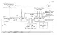
- FIG. 4shows an instrumented chiller system, allowing periodic or batch reoptimization, or allowing continuous closed loop feedback control of operating parameters.
- Compressor 100is connected to a power meter 101 , which accurately measures power consumption by measuring Volts and Amps drawn.
- the compressor 100produces hot dense refrigerant vapor in line 106 , which is fed to condenser 107 , where latent heat of vaporization and the heat added by the compressor 100 is shed.
- the refrigerantcarries a small amount of compressor lubricant oil.
- the condenser 107is subjected to measurements of temperature and pressure by temperature gage 155 and pressure gage 156 .
- the liquefied, cooled refrigerant, including a portion of mixed oilif fed through line 108 to an optional partial distillation apparatus 105 , and hence to evaporator 103 .
- the oil from the condenser 107accumulates in the evaporator 103 .
- the evaporator 103is subjected to measurements of refrigerant temperature and pressure by temperature gage 155 and pressure gage 156 .
- the chilled water in inlet line 152 and outlet line 154 of the evaporator 103are also subject to temperature and pressure measurement by temperature gage 155 and pressure gage 156 .
- the evaporated refrigerant from the evaporator 103returns to the compressor through line 104 .
- the power meter 101 , temperature gage 155 and pressure gage 156each provide data to a data acquisition system 157 , which produces output 158 representative of an efficiency of the chiller, in, for example, BTU/kWH.
- An oil sensor 159provides a continuous measurement of oil concentration in the evaporator 103 , and may be used to control the partial distillation apparatus 105 or determine the need for intermittent reoptimization, based on an optimum operating regime.
- the power meter 101 or the data acquisition system 157may provide surrogate measurements to estimate oil level in the evaporator or otherwise a need for oil removal.
- the efficiency of the chillervaries with the oil concentration in the evaporator 103 .
- Line 162shows a non-monotonic relationship.
- an operating regimemay thereafter be defined. While typically, after oil is removed from the evaporator 103 , it is not voluntarily replenished, a lower limit 160 of the operating regime defines, in a subsequent removal operation, a boundary beyond which it is not useful to extend. Complete oil removal is not only costly and directly inefficient, it may also result in reduced system efficiency. Likewise, when the oil level exceeds an upper boundary 161 of the operating regime, system efficiency drops and it is cost effective to service the chiller to restore optimum operation.
- the distance between the lower boundary 160 and upper boundarywill be much narrower than in a periodic maintenance system.
- the oil separatore.g., partial distillation apparatus 105 or other type system
- a closed loop feedback systemis itself typically less efficient than a larger system typically employed during periodic maintenance, so there are advantages to each type of arrangement.
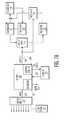
- FIG. 7Ashows a block diagram of a first embodiment of a control system according to the present invention.
- refrigerant chargeis controlled using an adaptive control 200 , with the control receiving refrigerant charge level 216 (from a level transmitter, e.g., Henry Valve Co., Melrose Park Ill. LCA series Liquid Level Column with E-9400 series Liquid Level Switches, digital output, or K-Tek Magnetostrictive Level Transmitters AT200 or AT600, analog output), optionally system power consumption (k Watt-hours), as well as thermodynamic parameters, including condenser and evaporator water temperature in and out, condenser and evaporator water flow rates and pressure, in and out, compressor RPM.
- a level transmittere.g., Henry Valve Co., Melrose Park Ill.
- LCA series Liquid Level Columnwith E-9400 series Liquid Level Switches, digital output, or K-Tek Magnetostrictive Level Transmitters AT200 or AT600, analog output
- These variablesare led into the adaptive control 200 employing a nonlinear model of the system, based on neural network 203 technology.
- This variablesare preprocessed to produce a set of derived variables from the input set, as well as to represent temporal parameters based on prior data sets.
- the neural network 203evaluates the input data set periodically, for example every 30 seconds, and produces an output control signal 209 or set of signals.
- the actual responseis compared with a predicted response based on the internal model defined by the neural network 203 by an adaptive control update subsystem 204 , and the neural network is updated 205 to reflect or take into account the “error”.
- a further output 206 of the system, from a diagnostic portion 205which may be integrated with the neural network or separate, indicates a likely error in either the sensors and network itself, or the plant being controlled.
- the controlled variableis, for example, the refrigerant charge in the system.
- liquid refrigerant from the evaporator 211is transferred to a storage vessel 212 through a valve 210 .
- gaseous refrigerantmay be returned to the compressor 214 suction, controlled by valve 215 , or liquid refrigerant pumped to the evaporator 211 .
- Refrigerant in the storage vessel 212may be subjected to analysis and purification.
- FIG. 7Bshows a signal-flow block diagram of a computer-based feedforward optimizing control system.
- Process variables 220are measured, checked for reliability, filtered, averaged, and stored in the computer database 222 .
- a regulatory system 223is provided as a front line control to keep the process variables 220 at a prescribed and desired slate of values.
- the conditioned set of measured variablesare compared in the regulatory system 223 with the desired set points from operator 224 A and optimization routine 224 B. Errors detected are then used to generate control actions that are then transmitted as outputs 22 D to final control elements in the process 221 .
- Set points for the regulatory system 223are derived either from operator input 224 A or from outputs of the optimization routine 224 B.
- the optimizer 226operates directly upon the model 227 in arriving at its optimal set-point state 224 B.
- the model 227is updated by means of a special routine 228 just prior to use by the optimizer 227 .
- the feedback update featureensures adequate mathematical process description in spite of minor instrumentation errors and, in addition, will compensate for discrepancies arising from simplifying assumptions incorporated in the model 227 .
- the controlled variablemay be, for example, compressor speed, alone or in addition to refrigerant charge level.
- the input variablesare, in this case, similar to those in Example 2, including refrigerant charge level, optionally system power consumption (kWatt-hours), as well as thermodynamic parameters, including condenser and evaporator water temperature in and out, condenser and evaporator water flow rates and pressure, in and out, compressor RPM, suction and discharge pressure and temperature, and ambient pressure and temperature.
- refrigerant charge leveloptionally system power consumption (kWatt-hours)
- thermodynamic parametersincluding condenser and evaporator water temperature in and out, condenser and evaporator water flow rates and pressure, in and out, compressor RPM, suction and discharge pressure and temperature, and ambient pressure and temperature.
- a control system 230which controls refrigerant charge level 231 , compressor speed 232 , and refrigerant oil concentration 233 in evaporator.
- a number of simplified relationshipsare provided in a database 234 , which segment the operational space of the system into a number of regions or planes based on sensor inputs.
- the sensitivity of the control system 230 to variations in inputs 235is adaptively determined by the control during operation, in order to optimize energy efficiency.
- Datais also stored in the database 234 as to the filling density of the operational space: when the set of input parameters identifies a well populated region of the operational space, a rapid transition is effected to achieve the calculated most efficient output conditions. On the other hand, if the region of the operational space is poorly populated, the control 230 provides a slow, searching alteration of the outputs seeking to explore the operational space to determine the optimal output set. This searching procedure also serves to populate the space, so that the control 230 will avoid the naive strategy after a few encounters.
- a statistical variabilityis determined for each region of the operational space. If the statistical variability is low, then the model for the region is deemed accurate, and continual searching of the local region is reduced. On the other hand, if the variability is high, the control 230 analyzes the input data set to determine a correlation between any available input 235 and the system efficiency, seeking to improve the model for that region stored in the database 234 . This correlation may be detected by searching the region through sensitivity testing of the input set with respect to changes in one or more of the outputs 231 , 232 , 233 . For each region, preferably a linear model is constructed relating the set of input variables and the optimal output variables. Alternately, a relatively simple non-linear network, such as a neural network, may be employed.
- the operational regionsfor example, segment the operational space into regions separated by 5% of refrigerant charge level, from ⁇ 40% to +20% of design, oil content of evaporator by 0.5% from 0% to 10%, and compressor speed, from minimum to maximum in 10-100 increments. It is also possible to provide non-uniformly spaced regions, or even adaptively sized regions based on the sensitivity of the outputs to input variations at respective portions of the input space.
- the control systemalso provides a set of special modes for system startup and shutdown. These are distinct from the normal operational modes, in that energy efficiency is not generally a primary consideration during these transitions, and because other control issues may be considered important. These modes also provide options for control system initialization and fail-safe operation.
- the neural network calculationsmay be implemented serially on a general purpose computer, e.g., an Intel Pentium III processor running Windows NT or a real time operating system, and therefore specialized hardware is typically not necessary.
- control systemprovide a diagnostic output 236 which “explains” the actions of the control, for example identifying, for any given control decision, the sensor inputs which had the greatest influence on the output state.
- diagnostic output 236which “explains” the actions of the control, for example identifying, for any given control decision, the sensor inputs which had the greatest influence on the output state.
- informationbe communicated to an operator or service engineer. This may be by way of a stored log, visual or audible indicators, telephone or Internet telecommunications, control network or local area network communications, radio frequency communication, or the like.
- a “failsafe” operational modeuntil maintenance may be performed.
Landscapes
- Engineering & Computer Science (AREA)
- Mechanical Engineering (AREA)
- General Engineering & Computer Science (AREA)
- Physics & Mathematics (AREA)
- Chemical & Material Sciences (AREA)
- Combustion & Propulsion (AREA)
- Thermal Sciences (AREA)
- Signal Processing (AREA)
- Mathematical Physics (AREA)
- Fuzzy Systems (AREA)
- Computer Vision & Pattern Recognition (AREA)
- Evolutionary Computation (AREA)
- Medical Informatics (AREA)
- Software Systems (AREA)
- General Physics & Mathematics (AREA)
- Automation & Control Theory (AREA)
- Artificial Intelligence (AREA)
- Health & Medical Sciences (AREA)
- Power Engineering (AREA)
- Analytical Chemistry (AREA)
- Air Conditioning Control Device (AREA)
- Feedback Control In General (AREA)
Abstract
Description
Claims (24)
Priority Applications (8)
| Application Number | Priority Date | Filing Date | Title |
|---|---|---|---|
| US09/577,703US6505475B1 (en) | 1999-08-20 | 2000-05-23 | Method and apparatus for measuring and improving efficiency in refrigeration systems |
| US10/338,941US7059143B1 (en) | 1999-08-20 | 2003-01-08 | Method and apparatus for measuring and improving efficiency in refrigeration systems |
| US11/182,249US7086240B1 (en) | 1999-08-20 | 2005-07-14 | Method and apparatus for measuring and improving efficiency in refrigeration systems |
| US11/463,101US7533536B1 (en) | 1999-08-20 | 2006-08-08 | Method and apparatus for measuring and improving efficiency in refrigeration systems |
| US12/468,506US7805952B1 (en) | 1999-08-20 | 2009-05-19 | Method and apparatus for measuring and improving efficiency in refrigeration systems |
| US12/898,289US8327653B1 (en) | 1999-08-20 | 2010-10-05 | Method and apparatus for measuring and improving efficiency in refrigeration systems |
| US13/707,829US9222712B1 (en) | 1999-08-20 | 2012-12-07 | Method and apparatus for measuring and improving efficiency in refrigeration systems |
| US14/980,962US10041713B1 (en) | 1999-08-20 | 2015-12-28 | Method and apparatus for measuring and improving efficiency in refrigeration systems |
Applications Claiming Priority (3)
| Application Number | Priority Date | Filing Date | Title |
|---|---|---|---|
| US15015299P | 1999-08-20 | 1999-08-20 | |
| US17499300P | 2000-01-07 | 2000-01-07 | |
| US09/577,703US6505475B1 (en) | 1999-08-20 | 2000-05-23 | Method and apparatus for measuring and improving efficiency in refrigeration systems |
Related Child Applications (2)
| Application Number | Title | Priority Date | Filing Date |
|---|---|---|---|
| US10/338,941Continuation-In-PartUS7059143B1 (en) | 1999-08-20 | 2003-01-08 | Method and apparatus for measuring and improving efficiency in refrigeration systems |
| US10/338,941ContinuationUS7059143B1 (en) | 1999-08-20 | 2003-01-08 | Method and apparatus for measuring and improving efficiency in refrigeration systems |
Publications (1)
| Publication Number | Publication Date |
|---|---|
| US6505475B1true US6505475B1 (en) | 2003-01-14 |
Family
ID=69953586
Family Applications (9)
| Application Number | Title | Priority Date | Filing Date |
|---|---|---|---|
| US09/577,703Expired - LifetimeUS6505475B1 (en) | 1999-08-20 | 2000-05-23 | Method and apparatus for measuring and improving efficiency in refrigeration systems |
| US10/338,941Expired - LifetimeUS7059143B1 (en) | 1999-08-20 | 2003-01-08 | Method and apparatus for measuring and improving efficiency in refrigeration systems |
| US11/182,249Expired - LifetimeUS7086240B1 (en) | 1999-08-20 | 2005-07-14 | Method and apparatus for measuring and improving efficiency in refrigeration systems |
| US11/463,101Expired - Fee RelatedUS7533536B1 (en) | 1999-08-20 | 2006-08-08 | Method and apparatus for measuring and improving efficiency in refrigeration systems |
| US12/468,506Expired - Fee RelatedUS7805952B1 (en) | 1999-08-20 | 2009-05-19 | Method and apparatus for measuring and improving efficiency in refrigeration systems |
| US12/898,289Expired - Fee RelatedUS8327653B1 (en) | 1999-08-20 | 2010-10-05 | Method and apparatus for measuring and improving efficiency in refrigeration systems |
| US13/707,829Expired - Fee RelatedUS9222712B1 (en) | 1999-08-20 | 2012-12-07 | Method and apparatus for measuring and improving efficiency in refrigeration systems |
| US14/980,962Expired - Fee RelatedUS10041713B1 (en) | 1999-08-20 | 2015-12-28 | Method and apparatus for measuring and improving efficiency in refrigeration systems |
| US16/056,082Expired - Fee RelatedUS10605507B1 (en) | 1999-08-20 | 2018-08-06 | Method and apparatus for measuring and improving efficiency in refrigeration systems |
Family Applications After (8)
| Application Number | Title | Priority Date | Filing Date |
|---|---|---|---|
| US10/338,941Expired - LifetimeUS7059143B1 (en) | 1999-08-20 | 2003-01-08 | Method and apparatus for measuring and improving efficiency in refrigeration systems |
| US11/182,249Expired - LifetimeUS7086240B1 (en) | 1999-08-20 | 2005-07-14 | Method and apparatus for measuring and improving efficiency in refrigeration systems |
| US11/463,101Expired - Fee RelatedUS7533536B1 (en) | 1999-08-20 | 2006-08-08 | Method and apparatus for measuring and improving efficiency in refrigeration systems |
| US12/468,506Expired - Fee RelatedUS7805952B1 (en) | 1999-08-20 | 2009-05-19 | Method and apparatus for measuring and improving efficiency in refrigeration systems |
| US12/898,289Expired - Fee RelatedUS8327653B1 (en) | 1999-08-20 | 2010-10-05 | Method and apparatus for measuring and improving efficiency in refrigeration systems |
| US13/707,829Expired - Fee RelatedUS9222712B1 (en) | 1999-08-20 | 2012-12-07 | Method and apparatus for measuring and improving efficiency in refrigeration systems |
| US14/980,962Expired - Fee RelatedUS10041713B1 (en) | 1999-08-20 | 2015-12-28 | Method and apparatus for measuring and improving efficiency in refrigeration systems |
| US16/056,082Expired - Fee RelatedUS10605507B1 (en) | 1999-08-20 | 2018-08-06 | Method and apparatus for measuring and improving efficiency in refrigeration systems |
Country Status (1)
| Country | Link |
|---|---|
| US (9) | US6505475B1 (en) |
Cited By (61)
| Publication number | Priority date | Publication date | Assignee | Title |
|---|---|---|---|---|
| US20020128730A1 (en)* | 2000-12-28 | 2002-09-12 | Akira Shimada | Disturbance estimated type control system, gas compressor control system and method of designing a disturbance estimated type control system |
| US20040044423A1 (en)* | 2001-03-02 | 2004-03-04 | Powitec Intelligent Technologies Gmbh | Method for controlling a thermodynamic process, in a particular a combustion process |
| US20040068390A1 (en)* | 2002-10-04 | 2004-04-08 | Saunders Michael A. | Compressor performance calculator |
| US20040069051A1 (en)* | 2001-07-06 | 2004-04-15 | Tadashi Hotta | Oil content measuring device and refrigeration system using the same |
| US20050192680A1 (en)* | 2004-02-27 | 2005-09-01 | Mark Cascia | System and method for optimizing global set points in a building environmental management system |
| US20050193752A1 (en)* | 2004-03-04 | 2005-09-08 | Eisenhower Bryan A. | Multi-variable control of refrigerant systems |
| DE102004011357A1 (en)* | 2004-03-05 | 2005-09-22 | Oliver Kohlsch | Evaluation unit for integrating into a heating arrangement, e.g. a heat pump comprises a measuring unit, a calculating unit for calculating relevant parameters and a display for displaying the parameters |
| US20050235663A1 (en)* | 2004-04-27 | 2005-10-27 | Pham Hung M | Compressor diagnostic and protection system and method |
| US20050246593A1 (en)* | 2004-04-19 | 2005-11-03 | Littrell Nathan B | Methods and apparatus for providing alarm notification |
| US20050251293A1 (en)* | 2001-05-15 | 2005-11-10 | Seigel Lawrence J | Method and system for evaluating the efficiency of an air conditioning apparatus |
| US20060026973A1 (en)* | 2004-08-03 | 2006-02-09 | Atchison Anthony E | Automated condensing unit test apparatus and associated methods |
| US20060059925A1 (en)* | 2004-09-22 | 2006-03-23 | Horan Christopher J | Process for refrigerant charge level detection using a neural net |
| US20060059924A1 (en)* | 2004-09-22 | 2006-03-23 | Horan Christopher J | Process for refrigerant charge level detection using a neural net having one output neuron |
| US20060090484A1 (en)* | 2004-11-02 | 2006-05-04 | Bell Brian D | HVAC monitor and superheat calculator system |
| US7059143B1 (en) | 1999-08-20 | 2006-06-13 | Hudson Technologies Inc. | Method and apparatus for measuring and improving efficiency in refrigeration systems |
| US20060213219A1 (en)* | 2003-10-08 | 2006-09-28 | Frank Beving | Distributed condensing units |
| US20060259285A1 (en)* | 2005-04-28 | 2006-11-16 | Vijay Bahel | Cooling system design simulator |
| US7155367B1 (en)* | 2005-01-25 | 2006-12-26 | Continuous Control Solutions, Inc. | Method for evaluating relative efficiency of equipment |
| US20070022062A1 (en)* | 2003-05-27 | 2007-01-25 | Ralph Grothmann | Method computer program with program code means, and computer program product for determining a future behavior of a dynamic system |
| US20070151269A1 (en)* | 2005-12-30 | 2007-07-05 | Johnson Controls Technology Company | System and method for level control in a flash tank |
| US20070250216A1 (en)* | 2006-04-25 | 2007-10-25 | Powitec Intelligent Technologies Gmbh | Procedure for regulating a combustion process |
| US20070277537A1 (en)* | 2006-05-31 | 2007-12-06 | Honeywell International, Inc. | Neural network based refrigerant charge detection algorithm for vapor compression systems |
| US20080216494A1 (en)* | 2006-09-07 | 2008-09-11 | Pham Hung M | Compressor data module |
| US20090119036A1 (en)* | 2007-11-02 | 2009-05-07 | Emerson Climate Technologies, Inc. | Compressor sensor module |
| US20090125257A1 (en)* | 2007-11-02 | 2009-05-14 | Emerson Climate Technologies, Inc. | Compressor sensor module |
| US7606683B2 (en) | 2004-01-27 | 2009-10-20 | Emerson Climate Technologies, Inc. | Cooling system design simulator |
| JP2010065998A (en)* | 2003-11-19 | 2010-03-25 | Massachusetts Inst Of Technology | Method for monitoring parameter and cooling device |
| US20120041608A1 (en)* | 2002-12-09 | 2012-02-16 | Hudson Technologies, Inc. | Method and apparatus for optimizing refrigeration systems |
| US8393169B2 (en) | 2007-09-19 | 2013-03-12 | Emerson Climate Technologies, Inc. | Refrigeration monitoring system and method |
| US8590325B2 (en) | 2006-07-19 | 2013-11-26 | Emerson Climate Technologies, Inc. | Protection and diagnostic module for a refrigeration system |
| CN103573604A (en)* | 2013-10-31 | 2014-02-12 | 广东美芝制冷设备有限公司 | Measuring device and oil-in-refrigerant content measuring method for compressor system |
| US20140245767A1 (en)* | 2011-10-17 | 2014-09-04 | Sanden Corporation | Vehicle Air Conditioning Apparatus |
| US8964338B2 (en) | 2012-01-11 | 2015-02-24 | Emerson Climate Technologies, Inc. | System and method for compressor motor protection |
| US8974573B2 (en) | 2004-08-11 | 2015-03-10 | Emerson Climate Technologies, Inc. | Method and apparatus for monitoring a refrigeration-cycle system |
| US9002532B2 (en) | 2012-06-26 | 2015-04-07 | Johnson Controls Technology Company | Systems and methods for controlling a chiller plant for a building |
| US9285802B2 (en) | 2011-02-28 | 2016-03-15 | Emerson Electric Co. | Residential solutions HVAC monitoring and diagnosis |
| US9310094B2 (en) | 2007-07-30 | 2016-04-12 | Emerson Climate Technologies, Inc. | Portable method and apparatus for monitoring refrigerant-cycle systems |
| US9310439B2 (en) | 2012-09-25 | 2016-04-12 | Emerson Climate Technologies, Inc. | Compressor having a control and diagnostic module |
| US9322127B2 (en) | 2013-05-22 | 2016-04-26 | Whirlpool Corporation | Method of operating a home appliance |
| US9480177B2 (en) | 2012-07-27 | 2016-10-25 | Emerson Climate Technologies, Inc. | Compressor protection module |
| US9551504B2 (en) | 2013-03-15 | 2017-01-24 | Emerson Electric Co. | HVAC system remote monitoring and diagnosis |
| US9638436B2 (en) | 2013-03-15 | 2017-05-02 | Emerson Electric Co. | HVAC system remote monitoring and diagnosis |
| US9759465B2 (en) | 2011-12-27 | 2017-09-12 | Carrier Corporation | Air conditioner self-charging and charge monitoring system |
| US9765979B2 (en) | 2013-04-05 | 2017-09-19 | Emerson Climate Technologies, Inc. | Heat-pump system with refrigerant charge diagnostics |
| US9951981B2 (en) | 2014-07-17 | 2018-04-24 | Ford Global Technologies, Llc | System and method for managing lubricant within a vapor compression heat pump |
| US10247458B2 (en) | 2013-08-21 | 2019-04-02 | Carrier Corporation | Chilled water system efficiency improvement |
| US10488090B2 (en) | 2013-03-15 | 2019-11-26 | Emerson Climate Technologies, Inc. | System for refrigerant charge verification |
| US20190390885A1 (en)* | 2018-06-22 | 2019-12-26 | Emerson Climate Technologies Retail Solutions, Inc. | Systems And Methods For Optical Detection Of Refrigeration System Abnormalities |
| CN111023635A (en)* | 2018-10-09 | 2020-04-17 | 伟思环境技术有限公司 | Method and apparatus for providing a non-azeotropic refrigerant |
| US10838440B2 (en) | 2017-11-28 | 2020-11-17 | Johnson Controls Technology Company | Multistage HVAC system with discrete device selection prioritization |
| US10838441B2 (en) | 2017-11-28 | 2020-11-17 | Johnson Controls Technology Company | Multistage HVAC system with modulating device demand control |
| US10839302B2 (en) | 2015-11-24 | 2020-11-17 | The Research Foundation For The State University Of New York | Approximate value iteration with complex returns by bounding |
| US10935309B2 (en) | 2017-09-06 | 2021-03-02 | International Business Machines Corporation | Predictive maintenance of refrigeration cases |
| CN113686031A (en)* | 2020-05-19 | 2021-11-23 | 山东大学 | Loop heat pipe solar liquid level pattern recognition method based on machine learning |
| CN113720625A (en)* | 2021-08-24 | 2021-11-30 | 南京师范大学 | Performance test analysis method for non-azeotropic refrigerant frequency conversion freezing and refrigerating system |
| US11319949B2 (en)* | 2019-02-12 | 2022-05-03 | Hang Zhou Zeta Technology Co., Lts | Analysis method of absolute energy efficiency and relative energy efficiency of compressed air system |
| US11346255B2 (en)* | 2018-12-14 | 2022-05-31 | Climeon Ab | Method and controller for preventing formation of droplets in a heat exchanger |
| US11473796B2 (en)* | 2008-10-31 | 2022-10-18 | Optimum Energy Llc | Systems and methods to control energy consumption efficiency |
| US20230417429A1 (en)* | 2022-06-24 | 2023-12-28 | Nutech Ventures | Virtual Superheat Measurement Sensor for Refrigeration Cycle |
| CN118729483A (en)* | 2024-09-02 | 2024-10-01 | 浩鲸云计算科技股份有限公司 | Energy-saving optimization control method for MIMO water-cooled air-conditioning system based on MPC |
| CN119689871A (en)* | 2024-12-25 | 2025-03-25 | 徐州丰成盐化工有限公司 | Evaporation energy-saving self-adaptive regulation and control method and system under multi-parameter analysis |
Families Citing this family (32)
| Publication number | Priority date | Publication date | Assignee | Title |
|---|---|---|---|---|
| USD341427S (en)* | 1990-09-14 | 1993-11-16 | Walter Koll | Body roller |
| KR100758902B1 (en)* | 2004-11-23 | 2007-09-14 | 엘지전자 주식회사 | Multi air conditioning system and control method |
| US8301576B2 (en)* | 2005-10-27 | 2012-10-30 | Ca, Inc. | Weighted pattern learning for neural networks |
| US7337630B2 (en)* | 2005-11-10 | 2008-03-04 | Johnson Controls Technology Company | Compact evaporator for chiller application |
| EP1793296A1 (en)* | 2005-12-05 | 2007-06-06 | Insyst Ltd. | An apparatus and method for the analysis of a process having parameter-based faults |
| US7553996B2 (en)* | 2007-03-06 | 2009-06-30 | Conant Lawrence D | Gas clathrate hydrate compositions, synthesis and use |
| CN101311851B (en)* | 2007-05-25 | 2013-05-22 | 开利公司 | Modified fuzzy control for cooler electronic expansion valve |
| US8055453B2 (en)* | 2008-09-19 | 2011-11-08 | Raytheon Company | Sensing and estimating in-leakage air in a subambient cooling system |
| US10184700B2 (en)* | 2009-02-09 | 2019-01-22 | Total Green Mfg. Corp. | Oil return system and method for active charge control in an air conditioning system |
| US8515584B2 (en) | 2009-08-20 | 2013-08-20 | Transformative Wave Technologies Llc | Energy reducing retrofit method for a constant volume HVAC system |
| US8473080B2 (en)* | 2010-05-10 | 2013-06-25 | Johnson Controls Technology Company | Control of cooling towers for chilled fluid systems |
| US8412357B2 (en) | 2010-05-10 | 2013-04-02 | Johnson Controls Technology Company | Process control systems and methods having learning features |
| WO2013105087A1 (en)* | 2012-01-12 | 2013-07-18 | Lncon Systems Ltd. | Chiller control |
| US9175891B2 (en)* | 2012-12-28 | 2015-11-03 | Bosch Automotive Service Solutions Inc. | Method and system for a portable refrigerant recovery unit load controller |
| US11062404B2 (en)* | 2013-01-18 | 2021-07-13 | Powertron Global, Llc | Determining savings in climate control systems |
| US9494334B2 (en) | 2013-03-15 | 2016-11-15 | Transformative Wave Technologies Llc | Method of advanced digital economization |
| KR102198326B1 (en)* | 2013-12-26 | 2021-01-05 | 엘지전자 주식회사 | Air conditioner |
| WO2016120952A1 (en)* | 2015-01-26 | 2016-08-04 | 株式会社日立製作所 | Solid-liquid separation system |
| WO2017027716A1 (en) | 2015-08-11 | 2017-02-16 | Trane International Inc. | Refrigerant recovery and repurposing |
| DE102016214797A1 (en)* | 2016-08-09 | 2018-02-15 | Bayerische Motoren Werke Aktiengesellschaft | Consideration of the influence of oil in a climate-refrigeration cycle |
| US10465949B2 (en) | 2017-07-05 | 2019-11-05 | Lennox Industries Inc. | HVAC systems and methods with multiple-path expansion device subsystems |
| DE102017117370A1 (en)* | 2017-08-01 | 2019-02-07 | Vaillant Gmbh | Soft sensor for identification and control or control of a heat pump system |
| US10955179B2 (en) | 2017-12-29 | 2021-03-23 | Johnson Controls Technology Company | Redistributing refrigerant between an evaporator and a condenser of a vapor compression system |
| CN110376005B (en) | 2018-04-13 | 2023-08-22 | 开利公司 | Data processing method, refrigerant leakage detection method, system failure detection method, and system performance detection method |
| USD893319S1 (en)* | 2018-11-08 | 2020-08-18 | 3M Innovative Properties Company | Monitoring device |
| US11160393B2 (en)* | 2019-10-30 | 2021-11-02 | Hill Phoenix, Inc. | Systems and methods for reducing condensation in refrigerated cases |
| US11989042B1 (en)* | 2020-04-03 | 2024-05-21 | Oneevent Technologies, Inc. | Systems and methods for smart temperature control devices |
| CN112682910B (en)* | 2020-12-08 | 2021-11-23 | 珠海格力电器股份有限公司 | Method and system for switching operation modes of dual-power cooling system |
| WO2022165792A1 (en)* | 2021-02-07 | 2022-08-11 | Siemens Limited, Hong Kong | Method and system of sensor fault management |
| DE102021213446A1 (en) | 2021-11-29 | 2023-06-01 | Robert Bosch Gesellschaft mit beschränkter Haftung | Method of operating a heating device |
| EP4558730A1 (en)* | 2022-08-25 | 2025-05-28 | GEA Refrigeration Netherlands N.V. | Piston compressor |
| CN116430737B (en)* | 2023-06-13 | 2023-08-18 | 中国空气动力研究与发展中心设备设计与测试技术研究所 | Self-adaptive control method of input delay nonlinear system |
Citations (4)
| Publication number | Priority date | Publication date | Assignee | Title |
|---|---|---|---|---|
| US4365482A (en)* | 1978-08-24 | 1982-12-28 | Sixten Langgard | Device at heating or cooling unit |
| US4420947A (en)* | 1981-07-10 | 1983-12-20 | System Homes Company, Ltd. | Heat pump air conditioning system |
| US4484452A (en)* | 1983-06-23 | 1984-11-27 | The Trane Company | Heat pump refrigerant charge control system |
| US5611211A (en) | 1994-09-07 | 1997-03-18 | General Electric Company | Refirgeration system with electrically controlled refrigerant storage device |
Family Cites Families (675)
| Publication number | Priority date | Publication date | Assignee | Title |
|---|---|---|---|---|
| US2296822A (en) | 1938-04-23 | 1942-09-22 | Westinghouse Electric & Mfg Co | Air conditioning apparatus |
| US2526768A (en) | 1949-06-23 | 1950-10-24 | Pendergrass James Arthur | Safety gun rest |
| US2700151A (en) | 1949-10-28 | 1955-01-18 | Rca Corp | Electrical pulse analyzer |
| US2700195A (en) | 1952-06-24 | 1955-01-25 | Gen Motors Corp | Refrigerator door construction |
| US2700197A (en) | 1952-10-23 | 1955-01-25 | Gen Motors Corp | Sealing gasket |
| US2951349A (en) | 1958-06-23 | 1960-09-06 | Gen Electric | Variable capacity refrigeration system |
| US3232519A (en) | 1963-05-07 | 1966-02-01 | Vilter Manufacturing Corp | Compressor protection system |
| US3312081A (en) | 1965-08-03 | 1967-04-04 | Carrier Corp | Control apparatus for refrigeration system |
| US3423954A (en) | 1967-11-13 | 1969-01-28 | Westinghouse Electric Corp | Refrigeration systems with accumulator means |
| US3513662A (en) | 1968-11-12 | 1970-05-26 | Armour & Co | Feedback control system for sequencing motors |
| US3527059A (en) | 1968-12-26 | 1970-09-08 | Phillips Petroleum Co | Method of controlling parallel-operating refrigeration compressors |
| US3585451A (en) | 1969-12-24 | 1971-06-15 | Borg Warner | Solid state motor overload protection system |
| US3653783A (en) | 1970-08-17 | 1972-04-04 | Cooper Ind Inc | Compressor output control apparatus |
| US3735377A (en) | 1971-03-19 | 1973-05-22 | Phillips Petroleum Co | Monitoring and shutdown apparatus |
| DE2203047C3 (en) | 1972-01-22 | 1978-12-14 | Maschf Augsburg Nuernberg Ag | Device for monitoring the running quality of a piston of a reciprocating piston machine |
| US3767328A (en) | 1972-07-19 | 1973-10-23 | Gen Electric | Rotary compressor with capacity modulation |
| US3874187A (en) | 1974-04-26 | 1975-04-01 | Fedders Corp | Refrigerant compressor with overload protector |
| US3924972A (en) | 1974-10-29 | 1975-12-09 | Vilter Manufacturing Corp | Control means for a variable capacity rotary screw compressor |
| US4060716A (en) | 1975-05-19 | 1977-11-29 | Rockwell International Corporation | Method and apparatus for automatic abnormal events monitor in operating plants |
| US4033407A (en) | 1975-09-02 | 1977-07-05 | Hooker Chemicals & Plastics Corporation | Heat exchanger cleaning system |
| US4090248A (en) | 1975-10-24 | 1978-05-16 | Powers Regulator Company | Supervisory and control system for environmental conditioning equipment |
| US4152902A (en) | 1976-01-26 | 1979-05-08 | Lush Lawrence E | Control for refrigeration compressors |
| US4102150A (en) | 1976-11-01 | 1978-07-25 | Borg-Warner Corporation | Control system for refrigeration apparatus |
| US4071078A (en) | 1976-11-03 | 1978-01-31 | Padden William R | Hydronic heating and cooling system |
| US4084388A (en) | 1976-11-08 | 1978-04-18 | Honeywell Inc. | Refrigeration control system for optimum demand operation |
| US4112703A (en) | 1976-12-27 | 1978-09-12 | Borg-Warner Corporation | Refrigeration control system |
| US4132086A (en) | 1977-03-01 | 1979-01-02 | Borg-Warner Corporation | Temperature control system for refrigeration apparatus |
| US4151725A (en) | 1977-05-09 | 1979-05-01 | Borg-Warner Corporation | Control system for regulating large capacity rotating machinery |
| US4102394A (en) | 1977-06-10 | 1978-07-25 | Energy 76, Inc. | Control unit for oil wells |
| US4184341A (en) | 1978-04-03 | 1980-01-22 | Pet Incorporated | Suction pressure control system |
| US4382467A (en) | 1978-08-17 | 1983-05-10 | American Precision Industries Inc. | Heat exchanger of the tube and plate type |
| US4281358A (en) | 1978-09-01 | 1981-07-28 | Texas Instruments Incorporated | Multifunction dynamoelectric protection system |
| US4227862A (en) | 1978-09-19 | 1980-10-14 | Frick Company | Solid state compressor control system |
| US4246763A (en) | 1978-10-24 | 1981-01-27 | Honeywell Inc. | Heat pump system compressor fault detector |
| US4244749A (en) | 1978-11-24 | 1981-01-13 | The Johns Hopkins University | Ultrasonic cleaning method and apparatus for heat exchangers |
| US5079929A (en) | 1979-07-31 | 1992-01-14 | Alsenz Richard H | Multi-stage refrigeration apparatus and method |
| US4951475A (en) | 1979-07-31 | 1990-08-28 | Altech Controls Corp. | Method and apparatus for controlling capacity of a multiple-stage cooling system |
| US5115644A (en) | 1979-07-31 | 1992-05-26 | Alsenz Richard H | Method and apparatus for condensing and subcooling refrigerant |
| US5265434A (en) | 1979-07-31 | 1993-11-30 | Alsenz Richard H | Method and apparatus for controlling capacity of a multiple-stage cooling system |
| US4831832A (en) | 1979-07-31 | 1989-05-23 | Alsenz Richard H | Method and apparatus for controlling capacity of multiple compressors refrigeration system |
| US4612776A (en) | 1979-07-31 | 1986-09-23 | Alsenz Richard H | Method and apparatus for controlling capacity of a multiple-stage cooling system |
| US5067326A (en) | 1979-07-31 | 1991-11-26 | Alsenz Richard H | Method and apparatus for controlling capacity of a multiple-stage cooling system |
| SE427861B (en) | 1979-10-29 | 1983-05-09 | Saab Scania Ab | PROCEDURE FOR AVOIDING NORMAL COMBUSTIONS IN A COMBUSTION ENGINE AND ARRANGEMENTS FOR EXTENDING THE PROCEDURE |
| US4365487A (en) | 1980-02-06 | 1982-12-28 | Luke Limited | Refrigeration apparatus |
| US4502843A (en) | 1980-03-31 | 1985-03-05 | Noodle Corporation | Valveless free plunger and system for well pumping |
| US4345162A (en) | 1980-06-30 | 1982-08-17 | Honeywell Inc. | Method and apparatus for power load shedding |
| JPS5744788A (en) | 1980-08-30 | 1982-03-13 | Toyoda Autom Loom Works Ltd | Operation control method of compressor for vehicular air conditioner and its device |
| US4463576A (en) | 1980-09-22 | 1984-08-07 | General Motors Corporation | Solid state clutch cycler with charge protection |
| US4338791A (en)* | 1980-10-14 | 1982-07-13 | General Electric Company | Microcomputer control for heat pump system |
| US4390321A (en) | 1980-10-14 | 1983-06-28 | American Davidson, Inc. | Control apparatus and method for an oil-well pump assembly |
| US4333316A (en) | 1980-10-14 | 1982-06-08 | General Electric Company | Automatic control apparatus for a heat pump system |
| US4425010A (en) | 1980-11-12 | 1984-01-10 | Reliance Electric Company | Fail safe dynamoelectric machine bearing |
| US4384462A (en) | 1980-11-20 | 1983-05-24 | Friedrich Air Conditioning & Refrigeration Co. | Multiple compressor refrigeration system and controller thereof |
| US4505125A (en) | 1981-01-26 | 1985-03-19 | Baglione Richard A | Super-heat monitoring and control device for air conditioning refrigeration systems |
| US6866092B1 (en) | 1981-02-19 | 2005-03-15 | Stephen Molivadas | Two-phase heat-transfer systems |
| US4325223A (en)* | 1981-03-16 | 1982-04-20 | Cantley Robert J | Energy management system for refrigeration systems |
| US4399548A (en) | 1981-04-13 | 1983-08-16 | Castleberry Kimberly N | Compressor surge counter |
| JPS57207773A (en) | 1981-06-17 | 1982-12-20 | Taiheiyo Kogyo Kk | Method of controlling cooling circuit and its control valve |
| JPS58108361A (en) | 1981-12-21 | 1983-06-28 | サンデン株式会社 | Vehicle air conditioner control device |
| JPS58110317A (en) | 1981-12-23 | 1983-06-30 | Mitsubishi Heavy Ind Ltd | Vehicle air conditioning system |
| US4434390A (en) | 1982-01-15 | 1984-02-28 | Westinghouse Electric Corp. | Motor control apparatus with parallel input, serial output signal conditioning means |
| JPS58128078A (en) | 1982-01-27 | 1983-07-30 | Dainippon Screen Mfg Co Ltd | Constituting method for memory device |
| US4390922A (en) | 1982-02-04 | 1983-06-28 | Pelliccia Raymond A | Vibration sensor and electrical power shut off device |
| US4479389A (en) | 1982-02-18 | 1984-10-30 | Allied Corporation | Tuned vibration detector |
| US4431388A (en) | 1982-03-05 | 1984-02-14 | The Trane Company | Controlled suction unloading in a scroll compressor |
| US4467613A (en) | 1982-03-19 | 1984-08-28 | Emerson Electric Co. | Apparatus for and method of automatically adjusting the superheat setting of a thermostatic expansion valve |
| US4429578A (en) | 1982-03-22 | 1984-02-07 | General Electric Company | Acoustical defect detection system |
| US4494383A (en) | 1982-04-22 | 1985-01-22 | Mitsubishi Denki Kabushiki Kaisha | Air-conditioner for an automobile |
| US4437322A (en) | 1982-05-03 | 1984-03-20 | Carrier Corporation | Heat exchanger assembly for a refrigeration system |
| US4510576A (en) | 1982-07-26 | 1985-04-09 | Honeywell Inc. | Specific coefficient of performance measuring device |
| US4497031A (en) | 1982-07-26 | 1985-01-29 | Johnson Service Company | Direct digital control apparatus for automated monitoring and control of building systems |
| US4470092A (en) | 1982-09-27 | 1984-09-04 | Allen-Bradley Company | Programmable motor protector |
| US4843575A (en) | 1982-10-21 | 1989-06-27 | Crane Harold E | Interactive dynamic real-time management system |
| US4502842A (en) | 1983-02-02 | 1985-03-05 | Colt Industries Operating Corp. | Multiple compressor controller and method |
| FR2541761B1 (en)* | 1983-02-24 | 1989-02-10 | Zundel Daniel | PIPE HEAT EXCHANGER |
| US4858681A (en) | 1983-03-28 | 1989-08-22 | Tui Industries | Shell and tube heat exchanger |
| US4478051A (en) | 1983-05-06 | 1984-10-23 | Tyler Refrigeration Corporation | Electronic temperature control system |
| JPH0758069B2 (en) | 1983-09-09 | 1995-06-21 | 株式会社日立製作所 | Compressor motor controller |
| US4520674A (en) | 1983-11-14 | 1985-06-04 | Technology For Energy Corporation | Vibration monitoring device |
| USRE33267E (en) | 1983-12-12 | 1990-07-17 | The Foxboro Company | Pattern-recognizing self-tuning controller |
| US4630670A (en) | 1983-12-19 | 1986-12-23 | Carrier Corporation | Variable volume multizone system |
| US5190664A (en) | 1983-12-29 | 1993-03-02 | Union Oil Company Of California | Brine heat exchanger treatment method |
| JPS60147585A (en) | 1984-01-11 | 1985-08-03 | Hitachi Ltd | Compressor control method |
| US4748820A (en) | 1984-01-11 | 1988-06-07 | Copeland Corporation | Refrigeration system |
| US4555910A (en) | 1984-01-23 | 1985-12-03 | Borg-Warner Corporation | Coolant/refrigerant temperature control system |
| US4545210A (en) | 1984-04-06 | 1985-10-08 | Carrier Corporation | Electronic program control for a refrigeration unit |
| US4539940A (en) | 1984-04-26 | 1985-09-10 | Young Richard K | Tube and shell heat exchanger with annular distributor |
| US4645542A (en) | 1984-04-26 | 1987-02-24 | Anco Engineers, Inc. | Method of pressure pulse cleaning the interior of heat exchanger tubes located within a pressure vessel such as a tube bundle heat exchanger, boiler, condenser or the like |
| US4574871A (en) | 1984-05-07 | 1986-03-11 | Parkinson David W | Heat pump monitor apparatus for fault detection in a heat pump system |
| JPS60237502A (en) | 1984-05-10 | 1985-11-26 | Yamatake Honeywell Co Ltd | Complex control system |
| JPH0631625B2 (en) | 1984-05-25 | 1994-04-27 | 株式会社日立製作所 | Scroll fluid machinery |
| DE3420144A1 (en) | 1984-05-30 | 1985-12-05 | Loewe Pumpenfabrik GmbH, 2120 Lüneburg | CONTROL AND CONTROL SYSTEM, IN PARTICULAR. FOR WATERING VACUUM PUMPS |
| DE3422398A1 (en) | 1984-06-15 | 1985-12-19 | Knorr-Bremse GmbH, 8000 München | Method and apparatus for operating a screw compressor installation |
| US4651535A (en) | 1984-08-08 | 1987-03-24 | Alsenz Richard H | Pulse controlled solenoid valve |
| US5035119A (en) | 1984-08-08 | 1991-07-30 | Alsenz Richard H | Apparatus for monitoring solenoid expansion valve flow rates |
| US5392612A (en) | 1984-08-08 | 1995-02-28 | Richard H. Alsenz | Refrigeration system having a self adjusting control range |
| US4575318A (en) | 1984-08-16 | 1986-03-11 | Sundstrand Corporation | Unloading of scroll compressors |
| US4610610A (en) | 1984-08-16 | 1986-09-09 | Sundstrand Corporation | Unloading of scroll compressors |
| US4563878A (en) | 1984-12-13 | 1986-01-14 | Baglione Richard A | Super-heat monitoring and control device for air conditioning refrigeration systems |
| US4663725A (en) | 1985-02-15 | 1987-05-05 | Thermo King Corporation | Microprocessor based control system and method providing better performance and better operation of a shipping container refrigeration system |
| US4614089A (en) | 1985-03-19 | 1986-09-30 | General Services Engineering, Inc. | Controlled refrigeration system |
| JPS61167498U (en) | 1985-04-05 | 1986-10-17 | ||
| FR2582430B1 (en) | 1985-05-23 | 1987-10-23 | Euram Umpi Ltd | METHOD FOR TRANSMITTING SIGNALS INTENDED, PARTICULARLY FOR MONITORING SPECIAL EQUIPMENT, SUCH AS FOR EXAMPLE ALARM EQUIPMENT INSTALLED IN APARTMENTS, AND SYSTEM FOR CARRYING OUT SAID METHOD |
| JPH0641756B2 (en) | 1985-06-18 | 1994-06-01 | サンデン株式会社 | Variable capacity scroll type compressor |
| DE3674966D1 (en) | 1985-08-10 | 1990-11-22 | Sanden Corp | SPIRAL COMPRESSOR WITH DEVICE CONTROL DEVICE. |
| US4660386A (en) | 1985-09-18 | 1987-04-28 | Hansen John C | Diagnostic system for detecting faulty sensors in liquid chiller air conditioning system |
| US4653280A (en) | 1985-09-18 | 1987-03-31 | Hansen John C | Diagnostic system for detecting faulty sensors in a refrigeration system |
| FR2589561B1 (en) | 1985-11-05 | 1988-06-10 | Froilabo | METHOD FOR PROTECTING A REFRIGERATION SYSTEM AGAINST DEPOSITS OF ADDITIVES IN THE HEAT FLUID CIRCUIT, AND A CENTRAL IMPLEMENTING SUCH A METHOD |
| JPS62109000A (en) | 1985-11-07 | 1987-05-20 | Takao Sakamoto | Cleaning of internal surface of heat transfer tube in heat exchanger |
| US4964060A (en) | 1985-12-04 | 1990-10-16 | Hartsog Charles H | Computer aided building plan review system and process |
| EP0250488A1 (en) | 1985-12-24 | 1988-01-07 | Monitronix Limited | Electronic sequential fault finding system |
| US4831560A (en) | 1986-01-15 | 1989-05-16 | Zaleski James V | Method for testing auto electronics systems |
| DE3601817A1 (en) | 1986-01-22 | 1987-07-23 | Egelhof Fa Otto | CONTROL DEVICE FOR THE REFRIGERANT FLOW FOR EVAPORATING REFRIGERATION SYSTEMS OR HEAT PUMPS AND EXPANSION VALVES ARRANGED IN THE REFRIGERANT FLOW |
| US4811897A (en) | 1986-02-20 | 1989-03-14 | Mitsubishi Denki Kabushiki Kaisha | Duct type air conditioning system |
| US4755957A (en) | 1986-03-27 | 1988-07-05 | K-White Tools, Incorporated | Automotive air-conditioning servicing system and method |
| US5515267A (en) | 1986-04-04 | 1996-05-07 | Alsenz; Richard H. | Apparatus and method for refrigeration system control and display |
| US5191643A (en) | 1986-04-04 | 1993-03-02 | Alsenz Richard H | Method and apparatus for refrigeration control and display |
| JPS62258967A (en) | 1986-04-10 | 1987-11-11 | ダイキン工業株式会社 | Controller for chilling unit |
| JPS62186537U (en) | 1986-05-16 | 1987-11-27 | ||
| JP2730625B2 (en) | 1986-05-30 | 1998-03-25 | 松下電器産業株式会社 | Scroll compressor |
| US4829777A (en) | 1986-07-23 | 1989-05-16 | Nippondenso Co., Ltd. | Refrigeration system |
| US4747449A (en) | 1986-07-25 | 1988-05-31 | E. L. Nickell Co., Inc. | Heat exchanger for liquids |
| US4877382A (en) | 1986-08-22 | 1989-10-31 | Copeland Corporation | Scroll-type machine with axially compliant mounting |
| US5222867A (en)* | 1986-08-29 | 1993-06-29 | Walker Sr Frank J | Method and system for controlling a mechanical pump to monitor and optimize both reservoir and equipment performance |
| US4933668A (en) | 1986-09-29 | 1990-06-12 | Shepherd Intelligence Systems, Inc. | Aircraft security system |
| JPS63163739A (en) | 1986-12-26 | 1988-07-07 | 株式会社不二工機製作所 | Method of controlling refrigeration system |
| DE3882151T2 (en) | 1987-01-10 | 1993-11-18 | Sanden Corp | Power control device for a variable power compressor. |
| US4885707A (en) | 1987-02-19 | 1989-12-05 | Dli Corporation | Vibration data collecting and processing apparatus and method |
| IL85537A0 (en) | 1987-02-25 | 1988-08-31 | Prestcold Ltd | Refrigeration systems |
| DE3706152A1 (en) | 1987-02-26 | 1988-09-08 | Sueddeutsche Kuehler Behr | METHOD FOR CONTROLLING A VEHICLE AIR CONDITIONER AND VEHICLE AIR CONDITIONER FOR IMPLEMENTING THE METHOD |
| US5231980A (en) | 1987-03-04 | 1993-08-03 | Praxair Canada, Inc. | Process for the recovery of halogenated hydrocarbons in a gas stream |
| US4893480A (en) | 1987-03-13 | 1990-01-16 | Nippondenso Co., Ltd. | Refrigeration cycle control apparatus |
| US5110364A (en) | 1987-03-30 | 1992-05-05 | A.L. Sandpiper Corporation | Processes for decontaminating polluted substrates |
| DE3725754A1 (en) | 1987-08-04 | 1989-02-16 | Busch Dieter & Co Prueftech | DEVICE FOR MONITORING PUMPS FOR HAZARDOUS CAVITATION |
| US5073862A (en) | 1987-08-26 | 1991-12-17 | Carlson Peter J | Method and apparatus for diagnosing problems with the thermodynamic performance of a heat engine |
| US4854130A (en) | 1987-09-03 | 1989-08-08 | Hoshizaki Electric Co., Ltd. | Refrigerating apparatus |
| US4881184A (en) | 1987-09-08 | 1989-11-14 | Datac, Inc. | Turbine monitoring apparatus |
| US5195333A (en) | 1987-10-19 | 1993-03-23 | Steenburgh Leon R Jr | Refrigerant reclaim method and apparatus |
| US4798055A (en) | 1987-10-28 | 1989-01-17 | Kent-Moore Corporation | Refrigeration system analyzer |
| US5311451A (en) | 1987-11-06 | 1994-05-10 | M. T. Mcbrian Company, Inc. | Reconfigurable controller for monitoring and controlling environmental conditions |
| US4856286A (en) | 1987-12-02 | 1989-08-15 | American Standard Inc. | Refrigeration compressor driven by a DC motor |
| US4967567A (en) | 1987-12-10 | 1990-11-06 | Murray Corporation | System and method for diagnosing the operation of air conditioner systems |
| US4829779A (en) | 1987-12-15 | 1989-05-16 | Hussmann Corporation | Interface adapter for interfacing a remote controller with commercial refrigeration and environmental control systems |
| US4913625A (en) | 1987-12-18 | 1990-04-03 | Westinghouse Electric Corp. | Automatic pump protection system |
| US5006045A (en) | 1987-12-24 | 1991-04-09 | Seiko Epson Corporation | Scroll compressor with reverse rotation speed limiter |
| US4842044A (en) | 1987-12-28 | 1989-06-27 | Haven Energy, Ltd. | Furnace control system |
| JPH0816561B2 (en) | 1988-01-05 | 1996-02-21 | 三菱重工業株式会社 | Refrigerator control device |
| US5428966A (en) | 1988-01-21 | 1995-07-04 | Alsenz; Richard H. | Refrigeration system utilizing an expansion device in the evaporator |
| US4962648A (en) | 1988-02-15 | 1990-10-16 | Sanyo Electric Co., Ltd. | Refrigeration apparatus |
| US4951029A (en) | 1988-02-16 | 1990-08-21 | Interactive Technologies, Inc. | Micro-programmable security system |
| FR2628558A1 (en) | 1988-03-14 | 1989-09-15 | Scl Security Computer Line Srl | Self-contained security monitoring and alarm system - is used in home, vehicles, office contains microprocessor and sensors which monitor for almost every eventuality |
| US4885564A (en) | 1988-05-03 | 1989-12-05 | Thermo King Corporation | Power line carrier communication system for monitoring refrigerated containers |
| JP2834139B2 (en) | 1988-05-11 | 1998-12-09 | 株式会社日立製作所 | Refrigeration equipment |
| US4882747A (en) | 1988-05-12 | 1989-11-21 | Jerry Williams | Infrared communication apparatus for remote site applications |
| EP0345493B1 (en) | 1988-06-08 | 1994-03-09 | Landis & Gyr Technology Innovation AG | Arrangement for the surveillance, control and regulation of a technical installation of a building automation system |
| EP0351833B1 (en) | 1988-07-20 | 1996-06-12 | Mitsubishi Jukogyo Kabushiki Kaisha | Plant fault diagnosis system |
| US4916915A (en)* | 1988-08-12 | 1990-04-17 | Murray Corporation | Method of and system for determining refrigerant/lubricant ratio within enclosed flow apparatus |
| US4985857A (en) | 1988-08-19 | 1991-01-15 | General Motors Corporation | Method and apparatus for diagnosing machines |
| US4838037A (en) | 1988-08-24 | 1989-06-13 | American Standard Inc. | Solenoid valve with supply voltage variation compensation |
| US4884412A (en) | 1988-09-15 | 1989-12-05 | William Sellers | Compressor slugging protection device and method therefor |
| DE3833209C1 (en) | 1988-09-30 | 1990-03-29 | Danfoss A/S, Nordborg, Dk | |
| US5018357A (en) | 1988-10-11 | 1991-05-28 | Helix Technology Corporation | Temperature control system for a cryogenic refrigeration |
| US4928750A (en) | 1988-10-14 | 1990-05-29 | American Standard Inc. | VaV valve with PWM hot water coil |
| US5012651A (en) | 1988-12-28 | 1991-05-07 | Matsushita Electric Industrial Co., Ltd. | Heat pump apparatus |
| US5245836A (en) | 1989-01-09 | 1993-09-21 | Sinvent As | Method and device for high side pressure regulation in transcritical vapor compression cycle |
| FI88432C (en) | 1989-01-13 | 1993-05-10 | Halton Oy | FOERFARANDE FOER REGLERING OCH UPPRAETTHAOLLANDE AV LUFTSTROEMMAR OCH MOTSVARANDE I VENTILATIONSANLAEGGNINGAR OCH ETT VENTILATIONSSYSTEM I ENLIGHET MED FOERFARANDET |
| US5086385A (en) | 1989-01-31 | 1992-02-04 | Custom Command Systems | Expandable home automation system |
| JP2780301B2 (en) | 1989-02-02 | 1998-07-30 | 株式会社豊田自動織機製作所 | Variable capacity mechanism for scroll compressor |
| US4878355A (en) | 1989-02-27 | 1989-11-07 | Honeywell Inc. | Method and apparatus for improving cooling of a compressor element in an air conditioning system |
| US5109222A (en) | 1989-03-27 | 1992-04-28 | John Welty | Remote control system for control of electrically operable equipment in people occupiable structures |
| US5119466A (en) | 1989-05-24 | 1992-06-02 | Asmo Co., Ltd. | Control motor integrated with a direct current motor and a speed control circuit |
| AU5929190A (en) | 1989-06-02 | 1991-01-07 | Aisi Research Corporation | Appliance interface for exchanging data |
| JPH0359350A (en) | 1989-07-28 | 1991-03-14 | Toshiba Corp | air conditioner |
| DE3925090A1 (en) | 1989-07-28 | 1991-02-07 | Bbc York Kaelte Klima | METHOD FOR OPERATING A REFRIGERATION SYSTEM |
| US5243827A (en) | 1989-07-31 | 1993-09-14 | Hitachi, Ltd. | Overheat preventing method for prescribed displacement type compressor and apparatus for the same |
| DE3928430C1 (en) | 1989-08-28 | 1991-03-07 | Linde Ag, 6200 Wiesbaden, De | |
| US5058388A (en) | 1989-08-30 | 1991-10-22 | Allan Shaw | Method and means of air conditioning |
| JP2755469B2 (en) | 1989-09-27 | 1998-05-20 | 株式会社日立製作所 | Air conditioner |
| JP3137643B2 (en) | 1989-10-02 | 2001-02-26 | ローズマウント インコーポレイテッド | Control unit installed on site |
| US4949550A (en) | 1989-10-04 | 1990-08-21 | Thermo King Corporation | Method and apparatus for monitoring a transport refrigeration system and its conditioned load |
| US4974427A (en) | 1989-10-17 | 1990-12-04 | Copeland Corporation | Compressor system with demand cooling |
| US5056036A (en) | 1989-10-20 | 1991-10-08 | Pulsafeeder, Inc. | Computer controlled metering pump |
| US5199962B1 (en) | 1989-11-07 | 1995-02-07 | Wijmans Johannes G. | Process for removing condensable components from gas streams |
| US5205843A (en) | 1989-11-07 | 1993-04-27 | Membrane Technology And Research, Inc. | Process for removing condensable components from gas streams |
| EP0502877B1 (en) | 1989-11-07 | 2001-05-16 | Membrane Technology And Research, Inc. | Process for recovering condensable components from gas streams |
| US5032148A (en) | 1989-11-07 | 1991-07-16 | Membrane Technology & Research, Inc. | Membrane fractionation process |
| US5051720A (en) | 1989-11-13 | 1991-09-24 | Secure Telecom, Inc. | Remote control system using power line of remote site |
| US4939905A (en) | 1989-12-04 | 1990-07-10 | Kent-Moore Corporation | Recovery system for differing refrigerants |
| US5243831A (en) | 1990-01-12 | 1993-09-14 | Major Thomas O | Apparatus for purification and recovery of refrigerant |
| JP2810231B2 (en) | 1990-01-30 | 1998-10-15 | ジヨンソン・サービス・カンパニー | Method of locating data in distributed network system having nodes |
| US4972805A (en) | 1990-02-01 | 1990-11-27 | Mpr Associates, Inc. | Method and apparatus for removing foreign matter from heat exchanger tubesheets |
| JPH0625984B2 (en) | 1990-02-20 | 1994-04-06 | インターナシヨナル・ビジネス・マシーンズ・コーポレーシヨン | Multiprocessor system |
| US5031410A (en) | 1990-02-21 | 1991-07-16 | American Standard Inc. | Refrigeration system thermal purge apparatus |
| JPH03244983A (en) | 1990-02-23 | 1991-10-31 | Toshiba Corp | air conditioner |
| EP0518926B1 (en) | 1990-03-03 | 1995-08-16 | Cedardell Limited | Communications system |
| US5044166A (en) | 1990-03-05 | 1991-09-03 | Membrane Technology & Research, Inc. | Refrigeration process with purge and recovery of refrigerant |
| JPH06103130B2 (en) | 1990-03-30 | 1994-12-14 | 株式会社東芝 | Air conditioner |
| US5369735A (en)* | 1990-03-30 | 1994-11-29 | New Microtime Inc. | Method for controlling a 3D patch-driven special effects system |
| DE4010770C1 (en) | 1990-04-04 | 1991-11-21 | Danfoss A/S, Nordborg, Dk | |
| GB9008788D0 (en) | 1990-04-19 | 1990-06-13 | Whitbread & Co Plc | Diagnostic equipment |
| DE4016513A1 (en) | 1990-05-22 | 1991-11-28 | Adelmann Gmbh | METHOD AND SYSTEM FOR SEPARATING A MIXTURE FROM TWO GAS-SHAPED COMPONENTS |
| US5022234A (en) | 1990-06-04 | 1991-06-11 | General Motors Corporation | Control method for a variable displacement air conditioning system compressor |
| US5109700A (en) | 1990-07-13 | 1992-05-05 | Life Systems, Inc. | Method and apparatus for analyzing rotating machines |
| US5172562A (en) | 1990-07-20 | 1992-12-22 | Spx Corporation | Refrigerant recovery, purification and recharging system and method |
| US5226300A (en) | 1990-07-27 | 1993-07-13 | Ozone Environmental Industries, Inc. | Refrigerant recycling apparatus, method and system |
| US5076067A (en) | 1990-07-31 | 1991-12-31 | Copeland Corporation | Compressor with liquid injection |
| US5009074A (en) | 1990-08-02 | 1991-04-23 | General Motors Corporation | Low refrigerant charge protection method for a variable displacement compressor |
| US5444171A (en) | 1992-10-14 | 1995-08-22 | Showa Denko Kabushiki Kaisha | Method for purification of 1,1,1,2-tetrafluoroethane |
| GB9018372D0 (en) | 1990-08-21 | 1990-10-03 | Ici Plc | Separation process |
| US5379757A (en)* | 1990-08-28 | 1995-01-10 | Olympus Optical Co. Ltd. | Method of compressing endoscope image data based on image characteristics |
| US5271238A (en)* | 1990-09-14 | 1993-12-21 | Nartron Corporation | Environmental control system |
| US5012652A (en) | 1990-09-21 | 1991-05-07 | Carrier Corporation | Crankcase heater control for hermetic refrigerant compressors |
| CA2046548C (en) | 1990-10-01 | 2002-01-15 | Gary J. Anderson | Scroll machine with floating seal |
| US5156539A (en) | 1990-10-01 | 1992-10-20 | Copeland Corporation | Scroll machine with floating seal |
| US5224358A (en) | 1990-10-04 | 1993-07-06 | Nippondenso Co., Ltd. | Refrigerating apparatus and modulator |
| USRE36408E (en) | 1990-10-04 | 1999-11-30 | Nippondenso Co., Ltd. | Refrigerating apparatus and modulator |
| US5115406A (en) | 1990-10-05 | 1992-05-19 | Gateshead Manufacturing Corporation | Rotating machinery diagnostic system |
| DE69128996T2 (en) | 1990-10-10 | 1998-09-10 | Honeywell Inc | Identification of a process system |
| US5203178A (en) | 1990-10-30 | 1993-04-20 | Norm Pacific Automation Corp. | Noise control of air conditioner |
| US5167126A (en) | 1990-12-12 | 1992-12-01 | Cjs Enterprises, Inc. | Refrigerant recovery and recycling assembly |
| US5259210A (en) | 1991-01-10 | 1993-11-09 | Sanyo Electric Co., Ltd. | Refrigerating apparatus and method of controlling refrigerating apparatus in accordance with fuzzy reasoning |
| SE467801B (en) | 1991-01-10 | 1992-09-14 | Electrolux Ab | FROZEN FURNITURE WITH DEVICE TO PREVENT FROZEN IMAGE |
| US5065591A (en) | 1991-01-28 | 1991-11-19 | Carrier Corporation | Refrigeration temperature control system |
| US5209400A (en) | 1991-03-07 | 1993-05-11 | John M. Winslow | Portable calculator for refrigeration heating and air conditioning equipment service |
| US5423192A (en) | 1993-08-18 | 1995-06-13 | General Electric Company | Electronically commutated motor for driving a compressor |
| US5134859A (en) | 1991-03-29 | 1992-08-04 | General Electric Company | Excess refrigerant accumulator for multievaporator vapor compression refrigeration cycles |
| US5123256A (en) | 1991-05-07 | 1992-06-23 | American Standard Inc. | Method of compressor staging for a multi-compressor refrigeration system |
| US5572425A (en)* | 1991-06-18 | 1996-11-05 | Ford Motor Company | Powered active suspension system responsive to anticipated power demand |
| JPH055564A (en) | 1991-06-28 | 1993-01-14 | Toshiba Corp | Air conditioner |
| US5372015A (en)* | 1991-07-05 | 1994-12-13 | Kabushiki Kaisha Toshiba | Air conditioner controller |
| US5176008A (en) | 1991-07-10 | 1993-01-05 | Steenburgh Leon R Jr | Refrigerant reclaim method and apparatus |
| US5245840A (en) | 1991-07-10 | 1993-09-21 | Steenburgh Leon R Jr | Refrigerant reclaim method and apparatus |
| US5279458A (en) | 1991-08-12 | 1994-01-18 | Carrier Corporation | Network management control |
| US5186012A (en)* | 1991-09-24 | 1993-02-16 | Institute Of Gas Technology | Refrigerant composition control system for use in heat pumps using non-azeotropic refrigerant mixtures |
| US5390206A (en) | 1991-10-01 | 1995-02-14 | American Standard Inc. | Wireless communication system for air distribution system |
| CH684965A5 (en) | 1991-10-18 | 1995-02-15 | Linde Ag | Method and apparatus for increasing the efficiency of compression devices. |
| US5189889A (en) | 1991-10-24 | 1993-03-02 | Cfc Solutions Corporation | Refrigerant reclaiming device |
| US5327735A (en) | 1991-10-28 | 1994-07-12 | The Youngstown Research & Development Co. | Refrigerant reclaiming and recycling system with evaporator chill bath |
| US5226472A (en) | 1991-11-15 | 1993-07-13 | Lab-Line Instruments, Inc. | Modulated temperature control for environmental chamber |
| US5203177A (en) | 1991-11-25 | 1993-04-20 | Spx Corporation | Refrigerant handling system with inlet refrigerant liquid/vapor flow control |
| US6081750A (en) | 1991-12-23 | 2000-06-27 | Hoffberg; Steven Mark | Ergonomic man-machine interface incorporating adaptive pattern recognition based control system |
| US5222369A (en) | 1991-12-31 | 1993-06-29 | K-Whit Tools, Inc. | Refrigerant recovery device with vacuum operated check valve |
| US5255527A (en)* | 1992-01-02 | 1993-10-26 | Carrier Corporation | Method of testing the purity of refrigerant flowing through a refrigeration system |
| US5272882A (en) | 1992-01-03 | 1993-12-28 | American Standard Inc. | Portable recycle/recovery/charging system with reconfigurable components |
| JP3100452B2 (en) | 1992-02-18 | 2000-10-16 | サンデン株式会社 | Variable capacity scroll compressor |
| US5519301A (en) | 1992-02-26 | 1996-05-21 | Matsushita Electric Industrial Co., Ltd. | Controlling/driving apparatus for an electrically-driven compressor in a car |
| US5203179A (en) | 1992-03-04 | 1993-04-20 | Ecoair Corporation | Control system for an air conditioning/refrigeration system |
| US5416781A (en) | 1992-03-17 | 1995-05-16 | Johnson Service Company | Integrated services digital network based facility management system |
| US5181389A (en) | 1992-04-26 | 1993-01-26 | Thermo King Corporation | Methods and apparatus for monitoring the operation of a transport refrigeration system |
| US5318224A (en) | 1992-05-04 | 1994-06-07 | David Darby | Method and apparatus for heating and cooling control |
| US5209076A (en) | 1992-06-05 | 1993-05-11 | Izon, Inc. | Control system for preventing compressor damage in a refrigeration system |
| US6964176B2 (en) | 1992-06-12 | 2005-11-15 | Kelix Heat Transfer Systems, Llc | Centrifugal heat transfer engine and heat transfer systems embodying the same |
| US5906108A (en) | 1992-06-12 | 1999-05-25 | Kidwell Environmental, Ltd., Inc. | Centrifugal heat transfer engine and heat transfer system embodying the same |
| US5299504A (en) | 1992-06-30 | 1994-04-05 | Technical Rail Products, Incorporated | Self-propelled rail heater car with movable induction heating coils |
| US5363662A (en) | 1992-06-30 | 1994-11-15 | Todack James J | Refrigerant recovery and recycling method and apparatus |
| US5709091A (en) | 1992-06-30 | 1998-01-20 | Todack; James Joseph | Refrigerant recovery and recycling method and apparatus |
| US5509786A (en) | 1992-07-01 | 1996-04-23 | Ubukata Industries Co., Ltd. | Thermal protector mounting structure for hermetic refrigeration compressors |
| US5329788A (en) | 1992-07-13 | 1994-07-19 | Copeland Corporation | Scroll compressor with liquid injection |
| US5277032A (en) | 1992-07-17 | 1994-01-11 | Cfc Reclamation And Recycling Service, Inc. | Apparatus for recovering and recycling refrigerants |
| US5456841A (en) | 1992-08-03 | 1995-10-10 | E. I. Du Pont De Nemours And Company | Process for separating and recovering halocarbons from mixtures thereof |
| US5224835A (en) | 1992-09-02 | 1993-07-06 | Viking Pump, Inc. | Shaft bearing wear detector |
| US5243829A (en) | 1992-10-21 | 1993-09-14 | General Electric Company | Low refrigerant charge detection using thermal expansion valve stroke measurement |
| US5568377A (en) | 1992-10-29 | 1996-10-22 | Johnson Service Company | Fast automatic tuning of a feedback controller |
| US5355305A (en) | 1992-10-29 | 1994-10-11 | Johnson Service Company | Pattern recognition adaptive controller |
| JPH06195322A (en) | 1992-10-29 | 1994-07-15 | Hitachi Ltd | Information processing device used as a general-purpose neurocomputer |
| US5450359A (en) | 1992-11-02 | 1995-09-12 | National Informatics Centre, Government Of India | Analog video interactive (AVI) PC Add-On Card for controlling consumer grade VHS-VCR |
| US5263331A (en) | 1992-11-10 | 1993-11-23 | Polar Industries Ltd. | Refrigerant recovery and recycling system |
| US5493867A (en) | 1992-11-18 | 1996-02-27 | Whirlpool Corporation | Fuzzy logic adaptive defrost control |
| US5481481A (en) | 1992-11-23 | 1996-01-02 | Architectural Engergy Corporation | Automated diagnostic system having temporally coordinated wireless sensors |
| US6243696B1 (en) | 1992-11-24 | 2001-06-05 | Pavilion Technologies, Inc. | Automated method for building a model |
| JP3290481B2 (en) | 1992-12-03 | 2002-06-10 | 東芝キヤリア株式会社 | Refrigeration cycle control device |
| US5381692A (en) | 1992-12-09 | 1995-01-17 | United Technologies Corporation | Bearing assembly monitoring system |
| US5359859A (en) | 1992-12-23 | 1994-11-01 | Russell Technical Products | Method and apparatus for recovering refrigerants |
| US5243828A (en) | 1992-12-28 | 1993-09-14 | Carrier Corporation | Control system for compressor protection in a manually operated refrigerant recovery apparatus |
| US5319943A (en) | 1993-01-25 | 1994-06-14 | Copeland Corporation | Frost/defrost control system for heat pump |
| US5231846A (en) | 1993-01-26 | 1993-08-03 | American Standard Inc. | Method of compressor staging for multi-compressor multi-circuited refrigeration systems |
| US5323385A (en) | 1993-01-27 | 1994-06-21 | Thermo King Corporation | Serial bus communication method in a refrigeration system |
| US5249429A (en) | 1993-02-08 | 1993-10-05 | Thermo King Corporation | Methods of operating a refrigeration system |
| US5313808A (en) | 1993-03-11 | 1994-05-24 | Scuderi Carmelo J | Portable refrigerant recycling unit for heat exchange with separate recovery unit |
| US5295362A (en) | 1993-04-06 | 1994-03-22 | Carrier Corporation | Electronic slide valve block |
| JP2897587B2 (en) | 1993-04-07 | 1999-05-31 | 株式会社日立製作所 | Absorption refrigerator |
| US5303560A (en) | 1993-04-15 | 1994-04-19 | Thermo King Corporation | Method and apparatus for monitoring and controlling the operation of a refrigeration unit |
| JP3364925B2 (en) | 1993-04-28 | 2003-01-08 | ダイキン工業株式会社 | Operation control device for air conditioner |
| US5875638A (en) | 1993-05-03 | 1999-03-02 | Copeland Corporation | Refrigerant recovery system |
| US5511387A (en) | 1993-05-03 | 1996-04-30 | Copeland Corporation | Refrigerant recovery system |
| US5440894A (en) | 1993-05-05 | 1995-08-15 | Hussmann Corporation | Strategic modular commercial refrigeration |
| US5327742A (en) | 1993-05-07 | 1994-07-12 | Carrier Corporation | Hierarchial control for discrete chiller units |
| US5963929A (en) | 1993-05-28 | 1999-10-05 | Maryland Technology Corporation | Recursive neural filters |
| US5649065A (en) | 1993-05-28 | 1997-07-15 | Maryland Technology Corporation | Optimal filtering by neural networks with range extenders and/or reducers |
| US5342186A (en) | 1993-06-02 | 1994-08-30 | General Motors Corporation | Axial actuator for unloading an orbital scroll type fluid material handling machine |
| US5282729A (en) | 1993-06-02 | 1994-02-01 | General Motors Corporation | Radical actuator for a de-orbiting scroll in a scroll type fluid handling machine |
| US5282728A (en) | 1993-06-02 | 1994-02-01 | General Motors Corporation | Inertial balance system for a de-orbiting scroll in a scroll type fluid handling machine |
| US5448230A (en) | 1993-06-25 | 1995-09-05 | Metscan, Incorporated | Remote data acquisition and communication system |
| US5651264A (en) | 1993-06-29 | 1997-07-29 | Siemens Electric Limited | Flexible process controller |
| US5467264A (en) | 1993-06-30 | 1995-11-14 | Microsoft | Method and system for selectively interdependent control of devices |
| US5381669A (en) | 1993-07-21 | 1995-01-17 | Copeland Corporation | Overcharge-undercharge diagnostic system for air conditioner controller |
| US5362206A (en) | 1993-07-21 | 1994-11-08 | Automation Associates | Pump control responsive to voltage-current phase angle |
| US5561817A (en) | 1993-08-16 | 1996-10-01 | Thermo King Corporation | Method of securely controlling direct memory access (DMA) of a shared memory by a DMA device on an expansion board |
| DE69427861T2 (en) | 1993-08-20 | 2002-04-11 | Woeel Elektronik Hb, Karlstad | SPEED CONTROL CIRCUIT FOR A SINGLE-PHASE OR THREE-PHASE MOTOR |
| US5701482A (en) | 1993-09-03 | 1997-12-23 | Hughes Aircraft Company | Modular array processor architecture having a plurality of interconnected load-balanced parallel processing nodes |
| US5956658A (en) | 1993-09-18 | 1999-09-21 | Diagnostic Instruments Limited | Portable data collection apparatus for collecting maintenance data from a field tour |
| JP2667950B2 (en) | 1993-09-20 | 1997-10-27 | 株式会社日立製作所 | Air conditioner and its address setting method |
| US6098425A (en) | 1993-10-01 | 2000-08-08 | Stothers; William R. | Thermodynamic separation |
| US5729623A (en) | 1993-10-18 | 1998-03-17 | Glory Kogyo Kabushiki Kaisha | Pattern recognition apparatus and method of optimizing mask for pattern recognition according to genetic algorithm |
| US5442930A (en) | 1993-10-22 | 1995-08-22 | Stieferman; Dale M. | One step refrigerant recover/recycle and reclaim unit |
| US5446216A (en) | 1993-11-01 | 1995-08-29 | E. I. Du Pont De Nemours And Company | Process for manufacture of high purity 1,1-dichlorotetrafluoroethane |
| US5390503A (en) | 1993-11-10 | 1995-02-21 | Cheng; Jung-Yuan | Recovery and recycling system for refrigerant |
| US5586446A (en) | 1993-11-16 | 1996-12-24 | Hoshizaki Denki Kabushiki Kaisha | Monitoring system for ice making machine |
| US5460006A (en) | 1993-11-16 | 1995-10-24 | Hoshizaki Denki Kabushiki Kaisha | Monitoring system for food storage device |
| US5452291A (en) | 1993-11-30 | 1995-09-19 | Panasonic Technologies, Inc. | Combination brouter and cluster controller |
| US5371019A (en) | 1993-12-02 | 1994-12-06 | Spx Corporation | Method and apparatus for analyzing refrigerant properties |
| US5566879A (en) | 1993-12-06 | 1996-10-22 | Comptel Domotique Inc. | System for centralized controlling of a plurality of temperature regulating devices |
| US5440890A (en) | 1993-12-10 | 1995-08-15 | Copeland Corporation | Blocked fan detection system for heat pump |
| US5743109A (en) | 1993-12-15 | 1998-04-28 | Schulak; Edward R. | Energy efficient domestic refrigeration system |
| US5460008A (en) | 1993-12-22 | 1995-10-24 | Novar Electronics Corporation | Method of refrigeration case synchronization for compressor optimization |
| US5533347A (en) | 1993-12-22 | 1996-07-09 | Novar Electronics Corporation | Method of refrigeration case control |
| US5347822A (en) | 1993-12-23 | 1994-09-20 | Uop | Process for drying CH2 F2 refrigerant utilizing zeolite |
| DE4344817C2 (en) | 1993-12-28 | 1995-11-16 | Hilti Ag | Method and device for hand-held machine tools to avoid accidents due to tool blocking |
| US5440895A (en) | 1994-01-24 | 1995-08-15 | Copeland Corporation | Heat pump motor optimization and sensor fault detection |
| US5440891A (en) | 1994-01-26 | 1995-08-15 | Hindmon, Jr.; James O. | Fuzzy logic based controller for cooling and refrigerating systems |
| US5353603A (en) | 1994-02-23 | 1994-10-11 | Wynn's Climate Systems, Inc. | Dual refrigerant recovery apparatus with single vacuum pump and control means |
| US5431026A (en) | 1994-03-03 | 1995-07-11 | General Electric Company | Refrigerant flow rate control based on liquid level in dual evaporator two-stage refrigeration cycles |
| US5415008A (en) | 1994-03-03 | 1995-05-16 | General Electric Company | Refrigerant flow rate control based on suction line temperature |
| US5426952A (en) | 1994-03-03 | 1995-06-27 | General Electric Company | Refrigerant flow rate control based on evaporator exit dryness |
| US5435145A (en) | 1994-03-03 | 1995-07-25 | General Electric Company | Refrigerant flow rate control based on liquid level in simple vapor compression refrigeration cycles |
| US5417075A (en) | 1994-03-07 | 1995-05-23 | Spx Corporation | Refrigerant filtation system with filter change indication |
| US5470442A (en) | 1994-03-11 | 1995-11-28 | E. I. Du Pont De Nemours And Company | Separating and removing impurities from tetrafluoroethanes by using extractive distillation |
| US5377493A (en) | 1994-03-28 | 1995-01-03 | Thermo King Corporation | Method and apparatus for evacuating and charging a refrigeration unit |
| US5428345A (en) | 1994-03-30 | 1995-06-27 | Sentrol, Inc. | Method of and apparatus for operating a security system to produce an alarm signal |
| US5425242A (en) | 1994-04-14 | 1995-06-20 | Uop | Process for recovery and purification of refrigerants with solid sorbents |
| US6230501B1 (en) | 1994-04-14 | 2001-05-15 | Promxd Technology, Inc. | Ergonomic systems and methods providing intelligent adaptive surfaces and temperature control |
| JPH07286750A (en) | 1994-04-18 | 1995-10-31 | Daikin Ind Ltd | Control device for air conditioner |
| US5446677A (en) | 1994-04-28 | 1995-08-29 | Johnson Service Company | Diagnostic system for use in an environment control network |
| US5499512A (en) | 1994-05-09 | 1996-03-19 | Thermo King Corporation | Methods and apparatus for converting a manually operable refrigeration unit to remote operation |
| US5377499A (en) | 1994-05-10 | 1995-01-03 | Hudson Technologies, Inc. | Method and apparatus for refrigerant reclamation |
| US5454229A (en) | 1994-05-18 | 1995-10-03 | Thermo King Corporation | Refrigeration unit control with shutdown evaluation and automatic restart |
| TW328190B (en) | 1994-06-14 | 1998-03-11 | Toshiba Co Ltd | Control device of brushless motor and method of fault detection and air conditioner |
| US5515693A (en) | 1994-06-15 | 1996-05-14 | Carrier Corporation | Enable system for a controlled atmosphere system for a refrigerated container |
| US5848402A (en) | 1994-07-07 | 1998-12-08 | Ai Ware, Inc. | Universal system for artificial intelligence based learning, categorization, and optimization |
| US5555195A (en) | 1994-07-22 | 1996-09-10 | Johnson Service Company | Controller for use in an environment control network capable of storing diagnostic information |
| US5682329A (en) | 1994-07-22 | 1997-10-28 | Johnson Service Company | On-line monitoring of controllers in an environment control network |
| US5581657A (en) | 1994-07-29 | 1996-12-03 | Zerox Corporation | System for integrating multiple genetic algorithm applications |
| US5511158A (en) | 1994-08-04 | 1996-04-23 | Thinking Machines Corporation | System and method for creating and evolving directed graphs |
| US5596507A (en) | 1994-08-15 | 1997-01-21 | Jones; Jeffrey K. | Method and apparatus for predictive maintenance of HVACR systems |
| US5437163A (en) | 1994-08-22 | 1995-08-01 | Thermo King Corporation | Method of logging data in a transport refrigeration unit |
| US5502974A (en) | 1994-09-01 | 1996-04-02 | Hudson Technologies, Inc. | Hydraulic system for recovering refrigerants |
| US5546757A (en) | 1994-09-07 | 1996-08-20 | General Electric Company | Refrigeration system with electrically controlled expansion valve |
| US5711159A (en) | 1994-09-07 | 1998-01-27 | General Electric Company | Energy-efficient refrigerator control system |
| US5910161A (en) | 1994-09-20 | 1999-06-08 | Fujita; Makoto | Refrigerating apparatus |
| CA2160338C (en) | 1994-10-13 | 2003-09-23 | Kenneth W. Oden | Electronic refrigeration control system |
| DE4436925C2 (en) | 1994-10-15 | 1998-05-14 | Danfoss As | Control device for the superheating temperature of at least one evaporator of a refrigeration system |
| ES2217283T3 (en) | 1994-10-19 | 2004-11-01 | Daikin Industries, Limited | TRANSMISSION DEVICE FOR AIR CONDITIONER. |
| US5610339A (en) | 1994-10-20 | 1997-03-11 | Ingersoll-Rand Company | Method for collecting machine vibration data |
| US5602757A (en) | 1994-10-20 | 1997-02-11 | Ingersoll-Rand Company | Vibration monitoring system |
| US5577390A (en) | 1994-11-14 | 1996-11-26 | Carrier Corporation | Compressor for single or multi-stage operation |
| KR0170695B1 (en) | 1994-11-15 | 1999-03-20 | 윤종용 | Refrigerator and heredity algorithm-fuzzy theory, its temperature apparatus and method |
| KR0182533B1 (en) | 1994-11-15 | 1999-05-01 | 윤종용 | Refrigerator and its temperature control method |
| US5713724A (en) | 1994-11-23 | 1998-02-03 | Coltec Industries Inc. | System and methods for controlling rotary screw compressors |
| US5497627A (en) | 1994-12-21 | 1996-03-12 | Commodore Laboratories, Inc. | Methods for purifying refrigerant compositions |
| US5626027A (en) | 1994-12-21 | 1997-05-06 | Carrier Corporation | Capacity control for multi-stage compressors |
| US5579993A (en) | 1995-01-06 | 1996-12-03 | Landis & Gyr Powers, Inc. | HVAC distribution system identification |
| US5514595A (en) | 1995-01-09 | 1996-05-07 | Spx Corporation | Method for analyzing refrigerant properties |
| US5546756A (en) | 1995-02-08 | 1996-08-20 | Eaton Corporation | Controlling an electrically actuated refrigerant expansion valve |
| DE19508476A1 (en) | 1995-03-09 | 1996-09-12 | Siemens Ag | Control system for a plant in the basic material or processing industry or similar |
| EP1434018A3 (en) | 1995-03-14 | 2009-07-01 | Hussmann Corporation | Refrigerated merchandiser with modular evaporator coils and electronic evaporator pressure regulator control |
| US5586444A (en) | 1995-04-25 | 1996-12-24 | Tyler Refrigeration | Control for commercial refrigeration system |
| US5502970A (en) | 1995-05-05 | 1996-04-02 | Copeland Corporation | Refrigeration control using fluctuating superheat |
| US5570258A (en) | 1995-05-11 | 1996-10-29 | Texas Instruments Incorporated | Phase monitor and protection apparatus |
| US5634345A (en) | 1995-06-06 | 1997-06-03 | Alsenz; Richard H. | Oil monitoring system |
| US5655380A (en) | 1995-06-06 | 1997-08-12 | Engelhard/Icc | Step function inverter system |
| US6047557A (en) | 1995-06-07 | 2000-04-11 | Copeland Corporation | Adaptive control for a refrigeration system using pulse width modulated duty cycle scroll compressor |
| US5741120A (en) | 1995-06-07 | 1998-04-21 | Copeland Corporation | Capacity modulated scroll machine |
| ES2247600T3 (en) | 1995-06-07 | 2006-03-01 | Copeland Corporation | HELICOIDAL MODULATED CAPACITY MACHINE. |
| CA2222632C (en) | 1995-06-19 | 2000-11-21 | Climate Supply (Atlantic) Inc. | Refrigerant separation system |
| US5596878A (en) | 1995-06-26 | 1997-01-28 | Thermo King Corporation | Methods and apparatus for operating a refrigeration unit |
| US5690963A (en) | 1995-06-30 | 1997-11-25 | The United States Of America As Represented By The Secretary Of The Navy | Freeze dried red blood cells |
| GB9513606D0 (en) | 1995-07-04 | 1995-09-06 | Boc Group Plc | Apparatus for chilling fluids |
| US5653282A (en) | 1995-07-19 | 1997-08-05 | The M. W. Kellogg Company | Shell and tube heat exchanger with impingement distributor |
| US5950709A (en) | 1995-07-21 | 1999-09-14 | Honeywell Inc. | Temperature control with stored multiple configuration programs |
| US5641270A (en) | 1995-07-31 | 1997-06-24 | Waters Investments Limited | Durable high-precision magnetostrictive pump |
| US5763959A (en) | 1995-08-14 | 1998-06-09 | Chambers; Michael | Control cabinet for building automation systems |
| US5727130A (en) | 1995-08-31 | 1998-03-10 | Motorola, Inc. | Genetic algorithm for constructing and tuning fuzzy logic system |
| US5707210A (en) | 1995-10-13 | 1998-01-13 | Copeland Corporation | Scroll machine with overheating protection |
| US5572643A (en) | 1995-10-19 | 1996-11-05 | Judson; David H. | Web browser with dynamic display of information objects during linking |
| US5655379A (en) | 1995-10-27 | 1997-08-12 | General Electric Company | Refrigerant level control in a refrigeration system |
| WO1997018636A2 (en) | 1995-11-13 | 1997-05-22 | Webtronics, Inc. | Control of remote devices using http protocol |
| KR0179763B1 (en) | 1995-11-23 | 1999-04-01 | 이종수 | Position control of machine tool |
| US5752385A (en) | 1995-11-29 | 1998-05-19 | Litton Systems, Inc. | Electronic controller for linear cryogenic coolers |
| US6005424A (en) | 1995-12-28 | 1999-12-21 | Dallas Semiconductor Corp | Integrated power switch for parasitically powered devices |
| DE19603175A1 (en) | 1996-01-30 | 1997-07-31 | Wilhelm Dr Buck | Method and device for monitoring, setting and regulating the filling level of a refrigerant evaporator |
| US5797729A (en) | 1996-02-16 | 1998-08-25 | Aspen Systems, Inc. | Controlling multiple variable speed compressors |
| US5731688A (en)* | 1996-03-13 | 1998-03-24 | Alaska Power Systems Inc. | Control system and circuits for distributed electrical-power generating stations |
| JP3751359B2 (en) | 1996-03-21 | 2006-03-01 | 本田技研工業株式会社 | Vibration noise control device |
| US5841652A (en)* | 1996-04-03 | 1998-11-24 | Scap Europa, S.A. | Adaptive-predictive control and optimization system |
| AU725476B2 (en) | 1996-04-12 | 2000-10-12 | York International Corporation | Fuzzy logic liquid level control |
| KR100195153B1 (en) | 1996-04-30 | 1999-06-15 | 윤종용 | Temperature Control Method of Independent Cooling Refrigerator with Rotating Blades |
| US5875430A (en) | 1996-05-02 | 1999-02-23 | Technology Licensing Corporation | Smart commercial kitchen network |
| US7877291B2 (en) | 1996-05-02 | 2011-01-25 | Technology Licensing Corporation | Diagnostic data interchange |
| US5877954A (en) | 1996-05-03 | 1999-03-02 | Aspen Technology, Inc. | Hybrid linear-neural network process control |
| US6110214A (en) | 1996-05-03 | 2000-08-29 | Aspen Technology, Inc. | Analyzer for modeling and optimizing maintenance operations |
| KR0176909B1 (en) | 1996-05-08 | 1999-10-01 | 구자홍 | Driving device of a linear compressor |
| US5735134A (en) | 1996-05-30 | 1998-04-07 | Massachusetts Institute Of Technology | Set point optimization in vapor compression cycles |
| US5669225A (en) | 1996-06-27 | 1997-09-23 | York International Corporation | Variable speed control of a centrifugal chiller using fuzzy logic |
| US6021369A (en) | 1996-06-27 | 2000-02-01 | Yamaha Hatsudoki Kabushiki Kaisha | Integrated controlling system |
| US6278986B1 (en) | 1996-06-27 | 2001-08-21 | Yahama Hatsudoki Kabushiki Kaisha | Integrated controlling system |
| US5782131A (en) | 1996-06-28 | 1998-07-21 | Lord; Richard G. | Flooded cooler with liquid level sensor |
| US5822740A (en) | 1996-06-28 | 1998-10-13 | Honeywell Inc. | Adaptive fuzzy controller that modifies membership functions |
| US5694210A (en) | 1996-06-28 | 1997-12-02 | The Board Of Trustees Of The University Of Illinois | Multi-purpose sensor system and sensing method using internally reflected light beams |
| GB2314915B (en)* | 1996-07-05 | 2000-01-26 | Jtl Systems Ltd | Defrost control method and apparatus |
| US5715704A (en) | 1996-07-08 | 1998-02-10 | Ranco Incorporated Of Delaware | Refrigeration system flow control expansion valve |
| US5946673A (en) | 1996-07-12 | 1999-08-31 | Francone; Frank D. | Computer implemented machine learning and control system |
| US5918474A (en) | 1996-07-30 | 1999-07-06 | Whirlpool Corporation | Fan motor on/off control system for a refrigeration appliance |
| EP0837291B1 (en) | 1996-08-22 | 2005-01-12 | Denso Corporation | Vapor compression type refrigerating system |
| US6246972B1 (en) | 1996-08-23 | 2001-06-12 | Aspen Technology, Inc. | Analyzer for modeling and optimizing maintenance operations |
| NL1003873C2 (en) | 1996-08-26 | 1998-03-03 | Hollandse Signaalapparaten Bv | Method for operating a fire control system. |
| US6032139A (en) | 1996-09-27 | 2000-02-29 | Yamaha Hatsudoki Kabushiki Kaisha | Electronic controller using genetic evolution techniques suitable for controlling a motor |
| JP3825845B2 (en) | 1996-09-27 | 2006-09-27 | ヤマハ発動機株式会社 | Evolutionary control method |
| US6314412B1 (en) | 1997-09-29 | 2001-11-06 | Yamaha Hatsudoki Kabushiki Kaisha | Evolutionary control of machine based on user's preference inferred from user's operation |
| US6324529B1 (en) | 1996-09-27 | 2001-11-27 | Yamaha Hatsudoki Kabushiki Kaisha | Evolutionary controlling system |
| JP3557053B2 (en) | 1996-09-30 | 2004-08-25 | 三洋電機株式会社 | Refrigerant compressor |
| JP3671552B2 (en) | 1996-09-30 | 2005-07-13 | ダイキン工業株式会社 | Oil separator for compressor and method for producing the same |
| US5822739A (en) | 1996-10-02 | 1998-10-13 | E-Stamp Corporation | System and method for remote postage metering |
| US6026652A (en) | 1996-10-18 | 2000-02-22 | Sanyo Electric Co., Ltd. | Air conditioning system having single bus line |
| US6017192A (en) | 1996-10-28 | 2000-01-25 | Clack; Richard N. | System and method for controlling screw compressors |
| US6446055B1 (en) | 1996-11-05 | 2002-09-03 | Stephen L. Grand | Process control |
| FR2756085B1 (en) | 1996-11-21 | 1998-12-31 | Air Liquide | FOOD PROCESSING PLANT CONTROLLED ACCORDING TO SETPOINT PARAMETERS |
| US5966954A (en) | 1996-12-04 | 1999-10-19 | Sanyo Electronic Co., Ltd. | Air conditioning system |
| US5802859A (en)* | 1996-12-16 | 1998-09-08 | Hudson Technologies, Inc. | Apparatus for recovering and analyzing volatile refrigerants |
| JP3410010B2 (en) | 1997-12-24 | 2003-05-26 | 株式会社日立製作所 | Subsystem migration method and information processing system |
| US6336050B1 (en) | 1997-02-04 | 2002-01-01 | British Telecommunications Public Limited Company | Method and apparatus for iteratively optimizing functional outputs with respect to inputs |
| US6128910A (en) | 1997-02-06 | 2000-10-10 | Federal Air Conditioning Technologies, Inc. | Diagnostic unit for an air conditioning system |
| US5761914A (en) | 1997-02-18 | 1998-06-09 | American Standard Inc. | Oil return from evaporator to compressor in a refrigeration system |
| JP3364826B2 (en) | 1997-02-24 | 2003-01-08 | 株式会社日立製作所 | Method and apparatus for creating distribution system configuration |
| JP3802965B2 (en) | 1997-03-21 | 2006-08-02 | ヴイ.ウリヤノフ セルゲイ | Self-organizing method and apparatus for optimal control of nonlinear physical control object |
| US5904049A (en) | 1997-03-31 | 1999-05-18 | General Electric Company | Refrigeration expansion control |
| US5995347A (en) | 1997-05-09 | 1999-11-30 | Texas Instruments Incorporated | Method and apparatus for multi-function electronic motor protection |
| US5975854A (en) | 1997-05-09 | 1999-11-02 | Copeland Corporation | Compressor with protection module |
| FR2763180B1 (en) | 1997-05-09 | 1999-06-04 | Schneider Electric Sa | METHOD AND APPARATUS FOR CONTROLLING A STARTER COMMUNICATING WITH A BUS |
| KR100225637B1 (en) | 1997-05-23 | 1999-10-15 | 윤종용 | Temperature controller of air conditioner |
| US6035651A (en)* | 1997-06-11 | 2000-03-14 | American Standard Inc. | Start-up method and apparatus in refrigeration chillers |
| WO1999004329A2 (en) | 1997-07-21 | 1999-01-28 | Kristin Ann Farry | Method of evolving classifier programs for signal processing and control |
| US5875637A (en) | 1997-07-25 | 1999-03-02 | York International Corporation | Method and apparatus for applying dual centrifugal compressors to a refrigeration chiller unit |
| US6006171A (en) | 1997-07-28 | 1999-12-21 | Vines; Caroline J. | Dynamic maintenance management system |
| JPH1163686A (en) | 1997-08-12 | 1999-03-05 | Zexel Corp | Refrigeration cycle |
| US5822996A (en) | 1997-08-22 | 1998-10-20 | Carrier Corporation | Vapor separation of variable capacity heat pump refrigerant |
| EP1022529A4 (en) | 1997-09-18 | 2002-09-25 | Matsushita Refrigeration | Self-diagnosing apparatus for refrigerator |
| US6206652B1 (en) | 1998-08-25 | 2001-03-27 | Copeland Corporation | Compressor capacity modulation |
| US5924295A (en) | 1997-10-07 | 1999-07-20 | Samsung Electronics Co., Ltd. | Method and apparatus for controlling initial operation of refrigerator |
| US5774761A (en) | 1997-10-14 | 1998-06-30 | Xerox Corporation | Machine set up procedure using multivariate modeling and multiobjective optimization |
| US6405122B1 (en) | 1997-10-14 | 2002-06-11 | Yamaha Hatsudoki Kabushiki Kaisha | Method and apparatus for estimating data for engine control |
| US5940337A (en) | 1997-10-23 | 1999-08-17 | Integrated Silicon Solution, Inc. | Method and apparatus for controlling memory address hold time |
| US6102665A (en) | 1997-10-28 | 2000-08-15 | Coltec Industries Inc | Compressor system and method and control for same |
| US5934091A (en) | 1997-10-31 | 1999-08-10 | Century Manufacturing Company | Refrigerant recovery and recycling system |
| US6105386A (en) | 1997-11-06 | 2000-08-22 | Denso Corporation | Supercritical refrigerating apparatus |
| US6830239B1 (en) | 1997-12-09 | 2004-12-14 | Paul R. Weber | Semi-frozen food product carbonator |
| US6058727A (en) | 1997-12-19 | 2000-05-09 | Carrier Corporation | Refrigeration system with integrated oil cooling heat exchanger |
| US6141980A (en) | 1998-02-05 | 2000-11-07 | Shaw; David N. | Evaporator generated foam control of compression systems |
| US6189335B1 (en) | 1998-02-06 | 2001-02-20 | Sanyo Electric Co., Ltd. | Multi-stage compressing refrigeration device and refrigerator using the device |
| DE19804904C1 (en) | 1998-02-07 | 1999-11-11 | Loh Kg Rittal Werk | Control cabinet with facilities for cooling the interior warm air |
| US5900801A (en) | 1998-02-27 | 1999-05-04 | Food Safety Solutions Corp. | Integral master system for monitoring food service requirements for compliance at a plurality of food service establishments |
| US5939974A (en) | 1998-02-27 | 1999-08-17 | Food Safety Solutions Corp. | System for monitoring food service requirements for compliance at a food service establishment |
| DE69914242T2 (en) | 1998-03-23 | 2004-11-04 | Hitachi, Ltd. | Control device for a brushless motor and machine with a brushless motor |
| US5946926A (en)* | 1998-04-07 | 1999-09-07 | Hartman; Thomas B. | Variable flow chilled fluid cooling system |
| US5984645A (en) | 1998-04-08 | 1999-11-16 | General Motors Corporation | Compressor with combined pressure sensor and high pressure relief valve assembly |
| US5937659A (en) | 1998-04-09 | 1999-08-17 | Carrier Corporation | Oil viscosity control method/system for a refrigeration unit |
| US6215405B1 (en) | 1998-04-23 | 2001-04-10 | Digital Security Controls Ltd. | Programmable temperature sensor for security system |
| JPH11327606A (en) | 1998-05-14 | 1999-11-26 | Yamaha Motor Co Ltd | Integrated control system |
| US6041605A (en) | 1998-05-15 | 2000-03-28 | Carrier Corporation | Compressor protection |
| US6349293B1 (en) | 1998-05-20 | 2002-02-19 | Yamaha Hatsudoki Kabushiki Kaisha | Method for optimization of a fuzzy neural network |
| FR2779215B1 (en) | 1998-05-28 | 2000-08-04 | Valeo Climatisation | AIR CONDITIONING CIRCUIT USING A SUPERCRITICAL REFRIGERANT FLUID, PARTICULARLY FOR VEHICLE |
| TW528847B (en) | 1998-06-18 | 2003-04-21 | Hitachi Ltd | Refrigerator |
| US6257324B1 (en) | 1998-06-30 | 2001-07-10 | Denso Corporation | Cooling apparatus boiling and condensing refrigerant |
| US6820157B1 (en) | 1998-06-30 | 2004-11-16 | International Business Machines Corporation | Apparatus, program product and method of replacing failed hardware device through concurrent maintenance operation |
| US6058729A (en) | 1998-07-02 | 2000-05-09 | Carrier Corporation | Method of optimizing cooling capacity, energy efficiency and reliability of a refrigeration system during temperature pull down |
| DE19832480A1 (en) | 1998-07-20 | 2000-01-27 | Behr Gmbh & Co | Vehicle air conditioning system with carbon dioxide working fluid is designed for limited variation in efficiency over a given range of high pressure deviation, avoiding need for controls on high pressure side |
| JP2000046456A (en) | 1998-07-29 | 2000-02-18 | Sankyo Seiki Mfg Co Ltd | Refrigerator |
| US6138467A (en) | 1998-08-20 | 2000-10-31 | Carrier Corporation | Steady state operation of a refrigeration system to achieve optimum capacity |
| US6178362B1 (en) | 1998-09-24 | 2001-01-23 | Silicon Energy Corp. | Energy management system and method |
| US7284391B2 (en) | 1998-10-06 | 2007-10-23 | Manitowoc Foodservice Companies, Inc. | Pump assembly for an ice making machine |
| US6463371B1 (en) | 1998-10-22 | 2002-10-08 | Yamaha Hatsudoki Kabushiki Kaisha | System for intelligent control of a vehicle suspension based on soft computing |
| US6098893A (en)* | 1998-10-22 | 2000-08-08 | Honeywell Inc. | Comfort control system incorporating weather forecast data and a method for operating such a system |
| US6216083B1 (en) | 1998-10-22 | 2001-04-10 | Yamaha Motor Co., Ltd. | System for intelligent control of an engine based on soft computing |
| US6415272B1 (en) | 1998-10-22 | 2002-07-02 | Yamaha Hatsudoki Kabushiki Kaisha | System for intelligent control based on soft computing |
| US6038871A (en) | 1998-11-23 | 2000-03-21 | General Motors Corporation | Dual mode control of a variable displacement refrigerant compressor |
| US6092380A (en) | 1998-11-23 | 2000-07-25 | Delphi Technologies, Inc. | Method for regulating the cooling performance of an air conditioning system |
| DE69914446T2 (en) | 1998-11-23 | 2004-07-01 | Delphi Technologies, Inc., Troy | Air conditioning diagnosis method |
| US6250560B1 (en) | 1998-12-21 | 2001-06-26 | Acutherm L.P. | Variable-air-volume diffuser actuator assembly and method |
| CA2356683A1 (en) | 1998-12-23 | 2000-07-06 | Venture Scientifics, Inc. | Compact refrigeration system |
| US6418356B1 (en) | 1998-12-31 | 2002-07-09 | Silicon Valley Group, Inc. | Method and apparatus for resolving conflicts in a substrate processing system |
| KR100548760B1 (en) | 1998-12-31 | 2006-04-14 | 주식회사 엘지이아이 | How to Operate Refrigerator's Home Bar Load |
| US20040095237A1 (en)* | 1999-01-09 | 2004-05-20 | Chen Kimball C. | Electronic message delivery system utilizable in the monitoring and control of remote equipment and method of same |
| US6212466B1 (en) | 2000-01-18 | 2001-04-03 | Yamaha Hatsudoki Kabushiki Kaisha | Optimization control method for shock absorber |
| US6170277B1 (en) | 1999-01-19 | 2001-01-09 | Carrier Corporation | Control algorithm for maintenance of discharge pressure |
| US6176686B1 (en) | 1999-02-19 | 2001-01-23 | Copeland Corporation | Scroll machine with capacity modulation |
| US6243548B1 (en) | 1999-02-25 | 2001-06-05 | Xerox Corporation | Method for controlling an imaging apparatus |
| US6129527A (en) | 1999-04-16 | 2000-10-10 | Litton Systems, Inc. | Electrically operated linear motor with integrated flexure spring and circuit for use in reciprocating compressor |
| US7219449B1 (en) | 1999-05-03 | 2007-05-22 | Promdx Technology, Inc. | Adaptively controlled footwear |
| US6185946B1 (en) | 1999-05-07 | 2001-02-13 | Thomas B. Hartman | System for sequencing chillers in a loop cooling plant and other systems that employ all variable-speed units |
| US6244055B1 (en) | 1999-06-01 | 2001-06-12 | Century Manufacturing Company | Refrigerant recovery and recycling system |
| US20010019120A1 (en) | 1999-06-09 | 2001-09-06 | Nicolas E. Schnur | Method of improving performance of refrigerant systems |
| US6170286B1 (en) | 1999-07-09 | 2001-01-09 | American Standard Inc. | Oil return from refrigeration system evaporator using hot oil as motive force |
| US6125642A (en) | 1999-07-13 | 2000-10-03 | Sporlan Valve Company | Oil level control system |
| US6166627A (en) | 1999-07-20 | 2000-12-26 | Reeley; Ronald B. | Mobile detection and alert system |
| US6179214B1 (en) | 1999-07-21 | 2001-01-30 | Carrier Corporation | Portable plug-in control module for use with the service modules of HVAC systems |
| US6505475B1 (en)* | 1999-08-20 | 2003-01-14 | Hudson Technologies Inc. | Method and apparatus for measuring and improving efficiency in refrigeration systems |
| JP3800900B2 (en) | 1999-09-09 | 2006-07-26 | 三菱電機株式会社 | Refrigerating refrigerator, operation method of freezing refrigerator |
| US6213731B1 (en) | 1999-09-21 | 2001-04-10 | Copeland Corporation | Compressor pulse width modulation |
| US6408227B1 (en) | 1999-09-29 | 2002-06-18 | The University Of Iowa Research Foundation | System and method for controlling effluents in treatment systems |
| US6446450B1 (en) | 1999-10-01 | 2002-09-10 | Firstenergy Facilities Services, Group, Llc | Refrigeration system with liquid temperature control |
| US6449715B1 (en) | 1999-10-04 | 2002-09-10 | Fisher-Rosemount Systems, Inc. | Process control configuration system for use with a profibus device network |
| US6260378B1 (en) | 1999-11-13 | 2001-07-17 | Reftec International, Inc. | Refrigerant purge system |
| US6202438B1 (en) | 1999-11-23 | 2001-03-20 | Scroll Technologies | Compressor economizer circuit with check valve |
| US6705094B2 (en) | 1999-12-01 | 2004-03-16 | Altech Controls Corporation | Thermally isolated liquid evaporation engine |
| US6233967B1 (en) | 1999-12-03 | 2001-05-22 | American Standard International Inc. | Refrigeration chiller oil recovery employing high pressure oil as eductor motive fluid |
| US6230497B1 (en) | 1999-12-06 | 2001-05-15 | Motorola, Inc. | Semiconductor circuit temperature monitoring and controlling apparatus and method |
| US6276901B1 (en) | 1999-12-13 | 2001-08-21 | Tecumseh Products Company | Combination sight glass and sump oil level sensor for a hermetic compressor |
| US6341252B1 (en) | 1999-12-21 | 2002-01-22 | Trw Inc. | Method and apparatus for controlling an actuatable occupant protection device |
| US6290043B1 (en) | 1999-12-29 | 2001-09-18 | Visteon Global Technologies, Inc. | Soft start compressor clutch |
| KR100318418B1 (en) | 1999-12-30 | 2001-12-22 | 신영주 | Oil separator embeded in compressor |
| US6453687B2 (en) | 2000-01-07 | 2002-09-24 | Robertshaw Controls Company | Refrigeration monitor unit |
| US6934862B2 (en) | 2000-01-07 | 2005-08-23 | Robertshaw Controls Company | Appliance retrofit monitoring device with a memory storing an electronic signature |
| DE10100826B4 (en) | 2000-02-01 | 2005-11-10 | Lg Electronics Inc. | Internet refrigerator and operating procedures for this |
| US6302654B1 (en) | 2000-02-29 | 2001-10-16 | Copeland Corporation | Compressor with control and protection system |
| WO2001069329A2 (en)* | 2000-03-10 | 2001-09-20 | Cyrano Sciences, Inc. | Control for an industrial process using one or more multidimensional variables |
| US6332327B1 (en) | 2000-03-14 | 2001-12-25 | Hussmann Corporation | Distributed intelligence control for commercial refrigeration |
| US6973794B2 (en) | 2000-03-14 | 2005-12-13 | Hussmann Corporation | Refrigeration system and method of operating the same |
| US20040016253A1 (en) | 2000-03-14 | 2004-01-29 | Hussmann Corporation | Refrigeration system and method of operating the same |
| US6647735B2 (en) | 2000-03-14 | 2003-11-18 | Hussmann Corporation | Distributed intelligence control for commercial refrigeration |
| US7047753B2 (en) | 2000-03-14 | 2006-05-23 | Hussmann Corporation | Refrigeration system and method of operating the same |
| US6999996B2 (en) | 2000-03-14 | 2006-02-14 | Hussmann Corporation | Communication network and method of communicating data on the same |
| US7000422B2 (en) | 2000-03-14 | 2006-02-21 | Hussmann Corporation | Refrigeration system and method of configuring the same |
| US6318101B1 (en) | 2000-03-15 | 2001-11-20 | Carrier Corporation | Method for controlling an electronic expansion valve based on cooler pinch and discharge superheat |
| US6360553B1 (en) | 2000-03-31 | 2002-03-26 | Computer Process Controls, Inc. | Method and apparatus for refrigeration system control having electronic evaporator pressure regulators |
| US6502409B1 (en) | 2000-05-03 | 2003-01-07 | Computer Process Controls, Inc. | Wireless method and apparatus for monitoring and controlling food temperature |
| US6427461B1 (en) | 2000-05-08 | 2002-08-06 | Lennox Industries Inc. | Space conditioning system with outdoor air and refrigerant heat control of dehumidification of an enclosed space |
| US6843065B2 (en) | 2000-05-30 | 2005-01-18 | Icc-Polycold System Inc. | Very low temperature refrigeration system with controlled cool down and warm up rates and long term heating capabilities |
| US6438981B1 (en) | 2000-06-06 | 2002-08-27 | Jay Daniel Whiteside | System for analyzing and comparing current and prospective refrigeration packages |
| CN1165011C (en) | 2000-06-19 | 2004-09-01 | Lg电子株式会社 | System and method of controlling a refrigerator capable of communicating |
| US6300872B1 (en) | 2000-06-20 | 2001-10-09 | Philips Electronics North America Corp. | Object proximity/security adaptive event detection |
| US6266968B1 (en) | 2000-07-14 | 2001-07-31 | Robert Walter Redlich | Multiple evaporator refrigerator with expansion valve |
| JP4517529B2 (en) | 2000-07-21 | 2010-08-04 | 株式会社日本自動車部品総合研究所 | Heat pump cycle, heating device, vehicle heating device, heating device, and vapor compression refrigeration cycle |
| US7252779B2 (en) | 2000-08-02 | 2007-08-07 | Mj Research Limited Partnership | Transesterification composition of fatty acid esters, and uses thereof |
| US7139564B2 (en) | 2000-08-08 | 2006-11-21 | Hebert Thomas H | Wireless communication device for field personnel |
| US6405548B1 (en) | 2000-08-11 | 2002-06-18 | General Electric Company | Method and apparatus for adjusting temperature using air flow |
| FI20001825L (en) | 2000-08-17 | 2002-02-18 | A Lab Oy | Storage system for open-field cultivated produce and storage box used therein |
| NO20005575D0 (en) | 2000-09-01 | 2000-11-03 | Sinvent As | Method and arrangement for defrosting cold / heat pump systems |
| TW593950B (en) | 2000-09-11 | 2004-06-21 | Toshiba Corp | Remote inspection system for refrigerator |
| FR2815397B1 (en) | 2000-10-12 | 2004-06-25 | Valeo Climatisation | VEHICLE AIR CONDITIONING DEVICE USING A SUPERCRITICAL CYCLE |
| JP2002130849A (en) | 2000-10-30 | 2002-05-09 | Calsonic Kansei Corp | Cooling cycle and its control method |
| US6324854B1 (en) | 2000-11-22 | 2001-12-04 | Copeland Corporation | Air-conditioning servicing system and method |
| KR100381166B1 (en) | 2000-12-13 | 2003-04-26 | 엘지전자 주식회사 | Refrigerator Setup System and Method for the same |
| FR2818742B1 (en) | 2000-12-22 | 2003-02-14 | Inst Francais Du Petrole | METHOD FOR FORMING AN OPTIMIZED NEURAL NETWORK MODULE FOR SIMULATING THE FLOW MODE OF A POLYPHASIC FLUID Vein |
| US6782706B2 (en) | 2000-12-22 | 2004-08-31 | General Electric Company | Refrigerator—electronics architecture |
| US6802186B2 (en) | 2001-01-05 | 2004-10-12 | General Electric Company | Refrigerator system and software architecture |
| US6539645B2 (en) | 2001-01-09 | 2003-04-01 | Mark Savarese | Drying apparatus and methods |
| JP2002206839A (en) | 2001-01-11 | 2002-07-26 | Nippon Kentetsu Co Ltd | Refrigeration equipment management system |
| US6609078B2 (en) | 2001-02-21 | 2003-08-19 | Emerson Retail Services, Inc. | Food quality and safety monitoring system |
| WO2002095308A2 (en) | 2001-02-23 | 2002-11-28 | Igc Polycold Systems, Inc. | Ultra-low temperature closed-loop recirculating gas chilling system |
| US20020118106A1 (en) | 2001-02-23 | 2002-08-29 | Brenn Eric Walter | Food safety discernment device |
| US6711907B2 (en) | 2001-02-28 | 2004-03-30 | Munters Corporation | Desiccant refrigerant dehumidifier systems |
| SK10812003A3 (en) | 2001-03-02 | 2004-01-08 | Powitec Intelligent Technologies Gmbh | Method for regulating a thermodynamic process in particular a combustion process |
| US6601397B2 (en) | 2001-03-16 | 2003-08-05 | Copeland Corporation | Digital scroll condensing unit controller |
| US6834510B1 (en) | 2001-04-12 | 2004-12-28 | Sun Microsystems, Inc. | Refrigerant management system for optimal compressor performance |
| EP1390618B1 (en) | 2001-04-23 | 2011-05-25 | Earnest Pacific Limited | Multi-stage centrifugal compressor driven by integral high speed motor |
| US6763676B2 (en) | 2001-04-30 | 2004-07-20 | Jones Brian C | Beverage dispenser |
| WO2002089385A2 (en) | 2001-04-30 | 2002-11-07 | Emerson Retail Services Inc. | Building system performance analysis |
| US6662865B2 (en) | 2001-04-30 | 2003-12-16 | Hewlett-Packard Development Company, L.P. | Multi-load thermal regulating system having electronic valve control |
| US6672381B2 (en) | 2001-04-30 | 2004-01-06 | Hewlett-Packard Development Company, L.P. | Multi-load thermal regulating system with multiple serial evaporators |
| US6675591B2 (en) | 2001-05-03 | 2004-01-13 | Emerson Retail Services Inc. | Method of managing a refrigeration system |
| US6668240B2 (en) | 2001-05-03 | 2003-12-23 | Emerson Retail Services Inc. | Food quality and safety model for refrigerated food |
| US6892546B2 (en) | 2001-05-03 | 2005-05-17 | Emerson Retail Services, Inc. | System for remote refrigeration monitoring and diagnostics |
| US6549135B2 (en) | 2001-05-03 | 2003-04-15 | Emerson Retail Services Inc. | Food-quality and shelf-life predicting method and system |
| US6923013B2 (en) | 2001-05-04 | 2005-08-02 | Carrier Corporation | Evaporator for medium temperature refrigerated merchandiser |
| US6973410B2 (en)* | 2001-05-15 | 2005-12-06 | Chillergy Systems, Llc | Method and system for evaluating the efficiency of an air conditioning apparatus |
| JP4578729B2 (en)* | 2001-07-06 | 2010-11-10 | 株式会社日本自動車部品総合研究所 | Oil fraction measuring apparatus and refrigeration apparatus using the same |
| US6718781B2 (en) | 2001-07-11 | 2004-04-13 | Thermo King Corporation | Refrigeration unit apparatus and method |
| WO2003006400A1 (en) | 2001-07-12 | 2003-01-23 | Ouellette Joseph P | Biomass heating system |
| US6755041B2 (en) | 2001-07-26 | 2004-06-29 | Carrier Corporation | Electrically powered trailer refrigeration unit |
| US6503048B1 (en) | 2001-08-27 | 2003-01-07 | Compressor Controls Corporation | Method and apparatus for estimating flow in compressors with sidestreams |
| US6796142B2 (en) | 2001-08-30 | 2004-09-28 | Integrated Marine Systems, Inc. | Continuous throughput blast freezer |
| US6880351B2 (en) | 2001-09-05 | 2005-04-19 | Be Intellectual Property, Inc. | Liquid galley refrigeration system for aircraft |
| US6474087B1 (en) | 2001-10-03 | 2002-11-05 | Carrier Corporation | Method and apparatus for the control of economizer circuit flow for optimum performance |
| DE10246004B4 (en) | 2001-10-03 | 2017-05-18 | Denso Corporation | Supercritical refrigeration cycle system and this using water heater |
| US6701236B2 (en) | 2001-10-19 | 2004-03-02 | Yamaha Hatsudoki Kabushiki Kaisha | Intelligent mechatronic control suspension system based on soft computing |
| EP1438539B1 (en) | 2001-10-26 | 2019-03-06 | Brooks Automation, Inc. | Methods of freezeout prevention for very low temperature mixed refrigerant systems |
| US6698228B2 (en) | 2001-11-02 | 2004-03-02 | Moobella, Llc | Method and apparatus for producing and dispensing an aerated and/or blended food product |
| US6817193B2 (en) | 2001-11-23 | 2004-11-16 | Daimlerchrysler Ag | Method for operating a refrigerant circuit, method for operating a motor vehicle driving engine, and refrigerant circuit |
| BR0106577B1 (en) | 2001-12-04 | 2010-05-04 | evaporator for refrigeration systems. | |
| US6828499B2 (en) | 2001-12-21 | 2004-12-07 | Marine Desalination Systems, L.L.C. | Apparatus and method for harvesting atmospheric moisture |
| US6619061B2 (en) | 2001-12-26 | 2003-09-16 | York International Corporation | Self-tuning pull-down fuzzy logic temperature control for refrigeration systems |
| CA2473792C (en) | 2002-01-29 | 2010-11-30 | Telefonaktiebolaget L M Ericsson (Publ) | A method and system of cooling a cabinet using dynamically controlled ciculating cooling fluid |
| US6631620B2 (en)* | 2002-01-31 | 2003-10-14 | General Electric Company | Adaptive refrigerator defrost method and apparatus |
| US6823684B2 (en) | 2002-02-08 | 2004-11-30 | Tim Allan Nygaard Jensen | System and method for cooling air |
| US6651448B2 (en) | 2002-02-12 | 2003-11-25 | Harold F. Ross | Ice cream machine including a controlled input to the freezing chamber |
| US6698214B2 (en) | 2002-02-22 | 2004-03-02 | Thar Technologies, Inc | Method of refrigeration with enhanced cooling capacity and efficiency |
| US7027958B2 (en) | 2002-02-27 | 2006-04-11 | Emerson Retail Services Inc. | Food quality and safety model for refrigerated food |
| US6606948B1 (en) | 2002-03-11 | 2003-08-19 | Heidelberger Druckmaschinen Ag | Method for controlling a chill roll system |
| US6996441B1 (en) | 2002-03-11 | 2006-02-07 | Advanced Micro Devices, Inc. | Forward-looking fan control using system operation information |
| US6907744B2 (en) | 2002-03-18 | 2005-06-21 | Manitowoc Foodservice Companies, Inc. | Ice-making machine with improved water curtain |
| US6779353B2 (en) | 2002-03-29 | 2004-08-24 | General Electric Company | Sealed system multiple speed compressor and fan control |
| US6751964B2 (en) | 2002-06-28 | 2004-06-22 | John C. Fischer | Desiccant-based dehumidification system and method |
| JP2004034943A (en) | 2002-07-08 | 2004-02-05 | Tgk Co Ltd | Control method for refrigeration cycle |
| IL166089A0 (en) | 2002-07-20 | 2006-01-15 | Idalex Technologies Inc | Evaporative duplex counterheat exchanger |
| US6950712B2 (en) | 2002-07-30 | 2005-09-27 | Yamaha Hatsudoki Kabushiki Kaisha | System and method for nonlinear dynamic control based on soft computing with discrete constraints |
| US6786056B2 (en) | 2002-08-02 | 2004-09-07 | Hewlett-Packard Development Company, L.P. | Cooling system with evaporators distributed in parallel |
| US6938433B2 (en) | 2002-08-02 | 2005-09-06 | Hewlett-Packard Development Company, Lp. | Cooling system with evaporators distributed in series |
| ES2377393T3 (en) | 2002-08-28 | 2012-03-27 | Remo Meister | Two-stage evaporation with liquid subcooling and suction steam superheat integrated in frequency controlled modular technique |
| US6745581B2 (en) | 2002-09-16 | 2004-06-08 | The Coca-Cola Company | Systems and methods for temperature control in refrigeration systems and heating systems |
| US6701723B1 (en) | 2002-09-26 | 2004-03-09 | Carrier Corporation | Humidity control and efficiency enhancement in vapor compression system |
| US6928389B2 (en) | 2002-10-04 | 2005-08-09 | Copeland Corporation | Compressor performance calculator |
| ITTO20030792A1 (en) | 2002-10-08 | 2004-04-09 | Danfoss As | VALVE CONTROL DEVICE AND PROCEDURE |
| AU2003282936A1 (en) | 2002-10-18 | 2004-05-04 | Symyx Technologies, Inc. | Environmental control system fluid sensing system and method comprising a sesnsor with a mechanical resonator |
| US6760221B2 (en) | 2002-10-23 | 2004-07-06 | International Business Machines Corporation | Evaporator with air cooling backup |
| US6889173B2 (en) | 2002-10-31 | 2005-05-03 | Emerson Retail Services Inc. | System for monitoring optimal equipment operating parameters |
| US6758054B2 (en) | 2002-11-19 | 2004-07-06 | Delphi Technologies, Inc. | Dual evaporator air conditioning system and method of use |
| WO2004049088A1 (en) | 2002-11-22 | 2004-06-10 | Radar Hvac-Refrigeration Inc. | Refrigeration monitor |
| CA2509207C (en)* | 2002-12-09 | 2012-04-24 | Hudson Technologies, Inc. | Method and apparatus for optimizing refrigeration systems |
| US8463441B2 (en)* | 2002-12-09 | 2013-06-11 | Hudson Technologies, Inc. | Method and apparatus for optimizing refrigeration systems |
| EP1570215B1 (en) | 2002-12-11 | 2007-12-05 | BMS-Energietechnik AG | Evaporation process control for use in refrigeration technology |
| NO317847B1 (en) | 2002-12-23 | 2004-12-20 | Sinvent As | Method for regulating a vapor compression system |
| US20040144849A1 (en) | 2003-01-28 | 2004-07-29 | Osman Ahmed | Building control system using integrated MEMS devices |
| JP3696224B2 (en) | 2003-03-19 | 2005-09-14 | 株式会社グリーンセイジュ | Drying system |
| US20040193330A1 (en) | 2003-03-26 | 2004-09-30 | Ingersoll-Rand Company | Method and system for controlling compressors |
| US6877328B2 (en) | 2003-04-23 | 2005-04-12 | Kendro Laboratory Products, Lp | Compressor operation following sensor failure |
| US7490477B2 (en) | 2003-04-30 | 2009-02-17 | Emerson Retail Services, Inc. | System and method for monitoring a condenser of a refrigeration system |
| KR100517935B1 (en) | 2003-05-26 | 2005-09-30 | 엘지전자 주식회사 | Driving control apparatus and method for reciprocating compressor |
| US7424807B2 (en) | 2003-06-11 | 2008-09-16 | Carrier Corporation | Supercritical pressure regulation of economized refrigeration system by use of an interstage accumulator |
| US6968708B2 (en) | 2003-06-23 | 2005-11-29 | Carrier Corporation | Refrigeration system having variable speed fan |
| US6901763B2 (en) | 2003-06-24 | 2005-06-07 | Modine Manufacturing Company | Refrigeration system |
| US7000413B2 (en) | 2003-06-26 | 2006-02-21 | Carrier Corporation | Control of refrigeration system to optimize coefficient of performance |
| US6820434B1 (en) | 2003-07-14 | 2004-11-23 | Carrier Corporation | Refrigerant compression system with selective subcooling |
| CA2949524C (en) | 2003-07-18 | 2017-07-04 | Bio-Rad Laboratories, Inc. | System and method for multi-analyte detection |
| US6813897B1 (en) | 2003-07-29 | 2004-11-09 | Hewlett-Packard Development Company, L.P. | Supplying power to at least one cooling system component |
| US7174726B2 (en) | 2003-08-07 | 2007-02-13 | Parker-Hannifin Corporation | Adjustable nozzle distributor |
| US7032654B2 (en) | 2003-08-19 | 2006-04-25 | Flatplate, Inc. | Plate heat exchanger with enhanced surface features |
| DE602004021821D1 (en) | 2003-08-25 | 2009-08-13 | Computer Process Controls Inc | COOLING CONTROL SYSTEM |
| JP2007507899A (en) | 2003-10-01 | 2007-03-29 | デルタ デザイン インコーポレーティッド | Electronic device temperature control apparatus and method |
| US7010927B2 (en) | 2003-11-07 | 2006-03-14 | Carrier Corporation | Refrigerant system with controlled refrigerant charge amount |
| US6845627B1 (en) | 2003-11-10 | 2005-01-25 | Be Intellectual Property, Inc. | Control system for an aircraft galley cooler |
| US20050103035A1 (en)* | 2003-11-19 | 2005-05-19 | Massachusetts Institute Of Technology | Oil circulation observer for HVAC systems |
| US6832504B1 (en) | 2003-11-19 | 2004-12-21 | Be Intellectual Property, Inc. | Liquid sensing system for an aircraft galley cooler using a two phase working fluid |
| US7357000B2 (en) | 2003-12-05 | 2008-04-15 | Dover Systems, Inc. | Display deck for a temperature controlled case |
| US7299649B2 (en) | 2003-12-09 | 2007-11-27 | Emerson Climate Technologies, Inc. | Vapor injection system |
| US7028492B2 (en) | 2004-01-30 | 2006-04-18 | Carrier Corporation | Hybrid dehumidication system |
| US6964172B2 (en) | 2004-02-24 | 2005-11-15 | Carrier Corporation | Adaptive defrost method |
| JP4265982B2 (en) | 2004-02-25 | 2009-05-20 | 三菱電機株式会社 | Equipment diagnostic equipment, refrigeration cycle equipment, refrigeration cycle monitoring system |
| US7093461B2 (en) | 2004-03-16 | 2006-08-22 | Hutchinson Fts, Inc. | Receiver-dryer for improving refrigeration cycle efficiency |
| US6981384B2 (en) | 2004-03-22 | 2006-01-03 | Carrier Corporation | Monitoring refrigerant charge |
| US7231778B2 (en) | 2004-03-29 | 2007-06-19 | Be Intellectual Property, Inc. | Cooling system for a commercial aircraft galley |
| US7405340B2 (en) | 2004-04-01 | 2008-07-29 | Bp Corporation North America Inc. | Process for recovering paraxylene utilizing ammonia absorption refrigeration |
| US7000415B2 (en) | 2004-04-29 | 2006-02-21 | Carrier Commercial Refrigeration, Inc. | Foul-resistant condenser using microchannel tubing |
| US7086241B2 (en) | 2004-05-28 | 2006-08-08 | Hydracool, Inc. | Hydraulic power unit for a refrigeration system |
| EP1607707A1 (en) | 2004-06-18 | 2005-12-21 | Ecole Polytechnique Federale De Lausanne (Epfl) | Bubble generator and heat transfer assembly |
| US7181928B2 (en) | 2004-06-29 | 2007-02-27 | York International Corporation | System and method for cooling a compressor motor |
| US7424343B2 (en) | 2004-08-11 | 2008-09-09 | Lawrence Kates | Method and apparatus for load reduction in an electric power system |
| US7275377B2 (en) | 2004-08-11 | 2007-10-02 | Lawrence Kates | Method and apparatus for monitoring refrigerant-cycle systems |
| US7143594B2 (en) | 2004-08-26 | 2006-12-05 | Thermo King Corporation | Control method for operating a refrigeration system |
| US7263852B2 (en) | 2004-08-30 | 2007-09-04 | Freus, Inc | Heat exchanger apparatus and method for evaporative cooling refrigeration unit |
| US7571622B2 (en) | 2004-09-13 | 2009-08-11 | Carrier Corporation | Refrigerant accumulator |
| US7552596B2 (en) | 2004-12-27 | 2009-06-30 | Carrier Corporation | Dual thermochromic liquid crystal temperature sensing for refrigerant charge indication |
| ATE553422T1 (en) | 2005-02-21 | 2012-04-15 | Computer Process Controls Inc | CONTROL AND MONITORING SYSTEM FOR COMPANIES |
| MX2008000389A (en)* | 2005-06-23 | 2008-03-07 | Lg Electronics Inc | Refrigerator. |
| JP4151679B2 (en) | 2005-07-07 | 2008-09-17 | 三菱電機株式会社 | Refrigeration cycle equipment |
| JP2009509118A (en)* | 2005-09-16 | 2009-03-05 | エルジー エレクトロニクス インコーポレイティド | refrigerator |
| EP2035762B1 (en)* | 2006-07-04 | 2012-09-05 | LG Electronics, Inc. | Refrigerator with wireless communication function |
| DE102006049396A1 (en)* | 2006-10-19 | 2008-04-24 | BSH Bosch und Siemens Hausgeräte GmbH | Household appliance with projection display |
| US8245522B2 (en)* | 2006-10-25 | 2012-08-21 | Lg Electronics Inc. | Display for refrigerator |
| JP4872627B2 (en)* | 2006-11-27 | 2012-02-08 | ダイキン工業株式会社 | Engine life prediction device and refrigeration system |
| US20090044549A1 (en)* | 2007-08-15 | 2009-02-19 | Sundhar Shaam P | Tabletop Quick Cooling Device |
| WO2009045829A1 (en)* | 2007-09-28 | 2009-04-09 | Gamma Service International, Inc. | Atmosphere handling system for confined volumes |
| US20090084118A1 (en)* | 2007-10-01 | 2009-04-02 | Kim Brian S | Refrigerator With Sign Panel |
| US20090165475A1 (en)* | 2007-12-28 | 2009-07-02 | Sam Wasserman | Icebox with external controls and temperature display |
| RU2529213C2 (en) | 2009-01-19 | 2014-09-27 | Найсвенд Лтд. | Device for dosaged dispensing of ordered frozen beverages |
| US8436489B2 (en)* | 2009-06-29 | 2013-05-07 | Lightsail Energy, Inc. | Compressed air energy storage system utilizing two-phase flow to facilitate heat exchange |
| JP5668755B2 (en) | 2010-06-18 | 2015-02-12 | コニカミノルタ株式会社 | FUEL CELL DEVICE AND FUEL CELL SYSTEM INCLUDING THE SAME |
- 2000
- 2000-05-23USUS09/577,703patent/US6505475B1/ennot_activeExpired - Lifetime
- 2003
- 2003-01-08USUS10/338,941patent/US7059143B1/ennot_activeExpired - Lifetime
- 2005
- 2005-07-14USUS11/182,249patent/US7086240B1/ennot_activeExpired - Lifetime
- 2006
- 2006-08-08USUS11/463,101patent/US7533536B1/ennot_activeExpired - Fee Related
- 2009
- 2009-05-19USUS12/468,506patent/US7805952B1/ennot_activeExpired - Fee Related
- 2010
- 2010-10-05USUS12/898,289patent/US8327653B1/ennot_activeExpired - Fee Related
- 2012
- 2012-12-07USUS13/707,829patent/US9222712B1/ennot_activeExpired - Fee Related
- 2015
- 2015-12-28USUS14/980,962patent/US10041713B1/ennot_activeExpired - Fee Related
- 2018
- 2018-08-06USUS16/056,082patent/US10605507B1/ennot_activeExpired - Fee Related
Patent Citations (4)
| Publication number | Priority date | Publication date | Assignee | Title |
|---|---|---|---|---|
| US4365482A (en)* | 1978-08-24 | 1982-12-28 | Sixten Langgard | Device at heating or cooling unit |
| US4420947A (en)* | 1981-07-10 | 1983-12-20 | System Homes Company, Ltd. | Heat pump air conditioning system |
| US4484452A (en)* | 1983-06-23 | 1984-11-27 | The Trane Company | Heat pump refrigerant charge control system |
| US5611211A (en) | 1994-09-07 | 1997-03-18 | General Electric Company | Refirgeration system with electrically controlled refrigerant storage device |
Cited By (147)
| Publication number | Priority date | Publication date | Assignee | Title |
|---|---|---|---|---|
| US10041713B1 (en) | 1999-08-20 | 2018-08-07 | Hudson Technologies, Inc. | Method and apparatus for measuring and improving efficiency in refrigeration systems |
| US7059143B1 (en) | 1999-08-20 | 2006-06-13 | Hudson Technologies Inc. | Method and apparatus for measuring and improving efficiency in refrigeration systems |
| US7086240B1 (en)* | 1999-08-20 | 2006-08-08 | Hudson Technologies Inc. | Method and apparatus for measuring and improving efficiency in refrigeration systems |
| US9222712B1 (en)* | 1999-08-20 | 2015-12-29 | Hudson Technologies, Inc. | Method and apparatus for measuring and improving efficiency in refrigeration systems |
| US7142930B2 (en)* | 2000-12-28 | 2006-11-28 | Calsonic Compressor Manufacturing Inc. | Disturbance estimated type control system, gas compressor control system and method of designing a disturbance estimated type control system |
| US20020128730A1 (en)* | 2000-12-28 | 2002-09-12 | Akira Shimada | Disturbance estimated type control system, gas compressor control system and method of designing a disturbance estimated type control system |
| US20040044423A1 (en)* | 2001-03-02 | 2004-03-04 | Powitec Intelligent Technologies Gmbh | Method for controlling a thermodynamic process, in a particular a combustion process |
| US7035717B2 (en)* | 2001-03-02 | 2006-04-25 | Powitec Intelligent Technologies Gmbh | Method for controlling a thermodynamic process, in particular a combustion process |
| US7945423B2 (en) | 2001-05-15 | 2011-05-17 | Chillergy Systems, Llc | Method and system for evaluating the efficiency of an air conditioning apparatus |
| US20080114569A1 (en)* | 2001-05-15 | 2008-05-15 | Seigel Lawrence J | Method and system for evaluating the efficiency of an air conditioning apparatus |
| US7349824B2 (en)* | 2001-05-15 | 2008-03-25 | Chillergy Systems, Llc | Method and system for evaluating the efficiency of an air conditioning apparatus |
| US20110218771A1 (en)* | 2001-05-15 | 2011-09-08 | Seigel Lawrence J | Method and system for evaluating the efficiency of an air conditioning apparatus |
| US20050251293A1 (en)* | 2001-05-15 | 2005-11-10 | Seigel Lawrence J | Method and system for evaluating the efficiency of an air conditioning apparatus |
| US6776029B2 (en)* | 2001-07-06 | 2004-08-17 | Denso Corporation | Oil content measuring device and refrigeration system using the same |
| US20040069051A1 (en)* | 2001-07-06 | 2004-04-15 | Tadashi Hotta | Oil content measuring device and refrigeration system using the same |
| US7451061B2 (en) | 2002-10-04 | 2008-11-11 | Copeland Corporation Llc | Compressor performance calculator |
| US20090037143A1 (en)* | 2002-10-04 | 2009-02-05 | Copeland Corporation Llc | Compressor performance calculator |
| US7917334B2 (en) | 2002-10-04 | 2011-03-29 | Copeland Corporation Llc | Compressor performance calculator |
| US6928389B2 (en)* | 2002-10-04 | 2005-08-09 | Copeland Corporation | Compressor performance calculator |
| US20050131654A1 (en)* | 2002-10-04 | 2005-06-16 | Saunders Michael A. | Compressor performance calculator |
| US20040068390A1 (en)* | 2002-10-04 | 2004-04-08 | Saunders Michael A. | Compressor performance calculator |
| US10436488B2 (en) | 2002-12-09 | 2019-10-08 | Hudson Technologies Inc. | Method and apparatus for optimizing refrigeration systems |
| US20120041608A1 (en)* | 2002-12-09 | 2012-02-16 | Hudson Technologies, Inc. | Method and apparatus for optimizing refrigeration systems |
| US9423165B2 (en)* | 2002-12-09 | 2016-08-23 | Hudson Technologies, Inc. | Method and apparatus for optimizing refrigeration systems |
| US8463441B2 (en)* | 2002-12-09 | 2013-06-11 | Hudson Technologies, Inc. | Method and apparatus for optimizing refrigeration systems |
| US7464061B2 (en)* | 2003-05-27 | 2008-12-09 | Siemens Aktiengesellschaft | Method, computer program with program code means, and computer program product for determining a future behavior of a dynamic system |
| US20070022062A1 (en)* | 2003-05-27 | 2007-01-25 | Ralph Grothmann | Method computer program with program code means, and computer program product for determining a future behavior of a dynamic system |
| US7823413B2 (en) | 2003-10-08 | 2010-11-02 | Emerson Climate Technologies, Inc. | Distributed condensing units |
| US20060213219A1 (en)* | 2003-10-08 | 2006-09-28 | Frank Beving | Distributed condensing units |
| JP2010065998A (en)* | 2003-11-19 | 2010-03-25 | Massachusetts Inst Of Technology | Method for monitoring parameter and cooling device |
| US7606683B2 (en) | 2004-01-27 | 2009-10-20 | Emerson Climate Technologies, Inc. | Cooling system design simulator |
| US20050192680A1 (en)* | 2004-02-27 | 2005-09-01 | Mark Cascia | System and method for optimizing global set points in a building environmental management system |
| US20050193752A1 (en)* | 2004-03-04 | 2005-09-08 | Eisenhower Bryan A. | Multi-variable control of refrigerant systems |
| US6993921B2 (en)* | 2004-03-04 | 2006-02-07 | Carrier Corporation | Multi-variable control of refrigerant systems |
| DE102004011357A1 (en)* | 2004-03-05 | 2005-09-22 | Oliver Kohlsch | Evaluation unit for integrating into a heating arrangement, e.g. a heat pump comprises a measuring unit, a calculating unit for calculating relevant parameters and a display for displaying the parameters |
| DE102004011357B4 (en)* | 2004-03-05 | 2006-07-13 | Oliver Kohlsch | Evaluation unit for integrating into a heating arrangement, e.g. a heat pump comprises a measuring unit, a calculating unit for calculating relevant parameters and a display for displaying the parameters |
| US7249287B2 (en) | 2004-04-19 | 2007-07-24 | General Electric Company | Methods and apparatus for providing alarm notification |
| US20050246593A1 (en)* | 2004-04-19 | 2005-11-03 | Littrell Nathan B | Methods and apparatus for providing alarm notification |
| US20050235662A1 (en)* | 2004-04-27 | 2005-10-27 | Pham Hung M | Compressor configuration system and method |
| US7484376B2 (en) | 2004-04-27 | 2009-02-03 | Emerson Climate Technologies, Inc. | Compressor diagnostic and protection system and method |
| US10335906B2 (en) | 2004-04-27 | 2019-07-02 | Emerson Climate Technologies, Inc. | Compressor diagnostic and protection system and method |
| US8474278B2 (en) | 2004-04-27 | 2013-07-02 | Emerson Climate Technologies, Inc. | Compressor diagnostic and protection system and method |
| US20050235664A1 (en)* | 2004-04-27 | 2005-10-27 | Pham Hung M | Compressor diagnostic and protection system and method |
| US20050235661A1 (en)* | 2004-04-27 | 2005-10-27 | Pham Hung M | Compressor diagnostic and protection system and method |
| US7412842B2 (en) | 2004-04-27 | 2008-08-19 | Emerson Climate Technologies, Inc. | Compressor diagnostic and protection system |
| US20050235663A1 (en)* | 2004-04-27 | 2005-10-27 | Pham Hung M | Compressor diagnostic and protection system and method |
| CN101865123B (en)* | 2004-04-27 | 2012-07-11 | 艾默生环境优化技术有限公司 | Compressor controller and compressor diagnosis and protection method |
| US20050235660A1 (en)* | 2004-04-27 | 2005-10-27 | Pham Hung M | Compressor diagnostic and protection system |
| US9121407B2 (en) | 2004-04-27 | 2015-09-01 | Emerson Climate Technologies, Inc. | Compressor diagnostic and protection system and method |
| US9669498B2 (en) | 2004-04-27 | 2017-06-06 | Emerson Climate Technologies, Inc. | Compressor diagnostic and protection system and method |
| WO2005108882A3 (en)* | 2004-04-27 | 2006-01-12 | Copeland Corp | Compressor diagnostic and protection system |
| US7905098B2 (en) | 2004-04-27 | 2011-03-15 | Emerson Climate Technologies, Inc. | Compressor diagnostic and protection system and method |
| CN101052847B (en)* | 2004-04-27 | 2010-05-05 | 谷轮公司 | Compressor diagnostic and protection system |
| US7878006B2 (en) | 2004-04-27 | 2011-02-01 | Emerson Climate Technologies, Inc. | Compressor diagnostic and protection system and method |
| US20060026973A1 (en)* | 2004-08-03 | 2006-02-09 | Atchison Anthony E | Automated condensing unit test apparatus and associated methods |
| US20070137224A1 (en)* | 2004-08-03 | 2007-06-21 | Rheem Manufacturing Company | Automated condensing unit test apparatus |
| US10558229B2 (en) | 2004-08-11 | 2020-02-11 | Emerson Climate Technologies Inc. | Method and apparatus for monitoring refrigeration-cycle systems |
| US9046900B2 (en) | 2004-08-11 | 2015-06-02 | Emerson Climate Technologies, Inc. | Method and apparatus for monitoring refrigeration-cycle systems |
| US9304521B2 (en) | 2004-08-11 | 2016-04-05 | Emerson Climate Technologies, Inc. | Air filter monitoring system |
| US9017461B2 (en) | 2004-08-11 | 2015-04-28 | Emerson Climate Technologies, Inc. | Method and apparatus for monitoring a refrigeration-cycle system |
| US8974573B2 (en) | 2004-08-11 | 2015-03-10 | Emerson Climate Technologies, Inc. | Method and apparatus for monitoring a refrigeration-cycle system |
| US9690307B2 (en) | 2004-08-11 | 2017-06-27 | Emerson Climate Technologies, Inc. | Method and apparatus for monitoring refrigeration-cycle systems |
| US9086704B2 (en) | 2004-08-11 | 2015-07-21 | Emerson Climate Technologies, Inc. | Method and apparatus for monitoring a refrigeration-cycle system |
| US9081394B2 (en) | 2004-08-11 | 2015-07-14 | Emerson Climate Technologies, Inc. | Method and apparatus for monitoring a refrigeration-cycle system |
| US9021819B2 (en) | 2004-08-11 | 2015-05-05 | Emerson Climate Technologies, Inc. | Method and apparatus for monitoring a refrigeration-cycle system |
| US9023136B2 (en) | 2004-08-11 | 2015-05-05 | Emerson Climate Technologies, Inc. | Method and apparatus for monitoring a refrigeration-cycle system |
| US20060059925A1 (en)* | 2004-09-22 | 2006-03-23 | Horan Christopher J | Process for refrigerant charge level detection using a neural net |
| US20060059924A1 (en)* | 2004-09-22 | 2006-03-23 | Horan Christopher J | Process for refrigerant charge level detection using a neural net having one output neuron |
| WO2006110165A3 (en)* | 2004-09-22 | 2006-12-28 | Northrop Grumman Corp | Process for refrigerant charge level detection using a neural net |
| US7111469B2 (en)* | 2004-09-22 | 2006-09-26 | Horan Christopher J | Process for refrigerant charge level detection using a neural net |
| US7134291B2 (en)* | 2004-09-22 | 2006-11-14 | Horan Christopher J | Process for refrigerant charge level detection using a neural net having one output neuron |
| US20070205296A1 (en)* | 2004-11-02 | 2007-09-06 | Stargate International, Inc. | Hvac monitor and superheat calculator system |
| US7234313B2 (en) | 2004-11-02 | 2007-06-26 | Stargate International, Inc. | HVAC monitor and superheat calculator system |
| US20060090484A1 (en)* | 2004-11-02 | 2006-05-04 | Bell Brian D | HVAC monitor and superheat calculator system |
| US7155367B1 (en)* | 2005-01-25 | 2006-12-26 | Continuous Control Solutions, Inc. | Method for evaluating relative efficiency of equipment |
| US20060259285A1 (en)* | 2005-04-28 | 2006-11-16 | Vijay Bahel | Cooling system design simulator |
| US7908126B2 (en) | 2005-04-28 | 2011-03-15 | Emerson Climate Technologies, Inc. | Cooling system design simulator |
| US20070151269A1 (en)* | 2005-12-30 | 2007-07-05 | Johnson Controls Technology Company | System and method for level control in a flash tank |
| US20070250216A1 (en)* | 2006-04-25 | 2007-10-25 | Powitec Intelligent Technologies Gmbh | Procedure for regulating a combustion process |
| US7637735B2 (en)* | 2006-04-25 | 2009-12-29 | Powitec Intelligent Technologies Gmbh | Procedure for regulating a combustion process |
| US20070277537A1 (en)* | 2006-05-31 | 2007-12-06 | Honeywell International, Inc. | Neural network based refrigerant charge detection algorithm for vapor compression systems |
| US7680751B2 (en) | 2006-05-31 | 2010-03-16 | Honeywell International Inc. | Neural network based refrigerant charge detection algorithm for vapor compression systems |
| US8590325B2 (en) | 2006-07-19 | 2013-11-26 | Emerson Climate Technologies, Inc. | Protection and diagnostic module for a refrigeration system |
| US9885507B2 (en) | 2006-07-19 | 2018-02-06 | Emerson Climate Technologies, Inc. | Protection and diagnostic module for a refrigeration system |
| US20080216494A1 (en)* | 2006-09-07 | 2008-09-11 | Pham Hung M | Compressor data module |
| US9823632B2 (en) | 2006-09-07 | 2017-11-21 | Emerson Climate Technologies, Inc. | Compressor data module |
| US9310094B2 (en) | 2007-07-30 | 2016-04-12 | Emerson Climate Technologies, Inc. | Portable method and apparatus for monitoring refrigerant-cycle systems |
| US10352602B2 (en) | 2007-07-30 | 2019-07-16 | Emerson Climate Technologies, Inc. | Portable method and apparatus for monitoring refrigerant-cycle systems |
| US9651286B2 (en) | 2007-09-19 | 2017-05-16 | Emerson Climate Technologies, Inc. | Refrigeration monitoring system and method |
| US8393169B2 (en) | 2007-09-19 | 2013-03-12 | Emerson Climate Technologies, Inc. | Refrigeration monitoring system and method |
| US9140728B2 (en) | 2007-11-02 | 2015-09-22 | Emerson Climate Technologies, Inc. | Compressor sensor module |
| US9194894B2 (en) | 2007-11-02 | 2015-11-24 | Emerson Climate Technologies, Inc. | Compressor sensor module |
| US10458404B2 (en) | 2007-11-02 | 2019-10-29 | Emerson Climate Technologies, Inc. | Compressor sensor module |
| US8335657B2 (en) | 2007-11-02 | 2012-12-18 | Emerson Climate Technologies, Inc. | Compressor sensor module |
| US8160827B2 (en) | 2007-11-02 | 2012-04-17 | Emerson Climate Technologies, Inc. | Compressor sensor module |
| US20090119036A1 (en)* | 2007-11-02 | 2009-05-07 | Emerson Climate Technologies, Inc. | Compressor sensor module |
| US20090125257A1 (en)* | 2007-11-02 | 2009-05-14 | Emerson Climate Technologies, Inc. | Compressor sensor module |
| US11473796B2 (en)* | 2008-10-31 | 2022-10-18 | Optimum Energy Llc | Systems and methods to control energy consumption efficiency |
| US9703287B2 (en) | 2011-02-28 | 2017-07-11 | Emerson Electric Co. | Remote HVAC monitoring and diagnosis |
| US10884403B2 (en) | 2011-02-28 | 2021-01-05 | Emerson Electric Co. | Remote HVAC monitoring and diagnosis |
| US10234854B2 (en) | 2011-02-28 | 2019-03-19 | Emerson Electric Co. | Remote HVAC monitoring and diagnosis |
| US9285802B2 (en) | 2011-02-28 | 2016-03-15 | Emerson Electric Co. | Residential solutions HVAC monitoring and diagnosis |
| US20140245767A1 (en)* | 2011-10-17 | 2014-09-04 | Sanden Corporation | Vehicle Air Conditioning Apparatus |
| US10214072B2 (en)* | 2011-10-17 | 2019-02-26 | Sanden Holdings Corporation | Vehicle air conditioning apparatus |
| US9759465B2 (en) | 2011-12-27 | 2017-09-12 | Carrier Corporation | Air conditioner self-charging and charge monitoring system |
| US8964338B2 (en) | 2012-01-11 | 2015-02-24 | Emerson Climate Technologies, Inc. | System and method for compressor motor protection |
| US9876346B2 (en) | 2012-01-11 | 2018-01-23 | Emerson Climate Technologies, Inc. | System and method for compressor motor protection |
| US9590413B2 (en) | 2012-01-11 | 2017-03-07 | Emerson Climate Technologies, Inc. | System and method for compressor motor protection |
| US9696054B2 (en) | 2012-06-26 | 2017-07-04 | Johnson Controls Technology Company | Systems and methods for controlling a central plant for a building |
| US9002532B2 (en) | 2012-06-26 | 2015-04-07 | Johnson Controls Technology Company | Systems and methods for controlling a chiller plant for a building |
| US9480177B2 (en) | 2012-07-27 | 2016-10-25 | Emerson Climate Technologies, Inc. | Compressor protection module |
| US10485128B2 (en) | 2012-07-27 | 2019-11-19 | Emerson Climate Technologies, Inc. | Compressor protection module |
| US10028399B2 (en) | 2012-07-27 | 2018-07-17 | Emerson Climate Technologies, Inc. | Compressor protection module |
| US9310439B2 (en) | 2012-09-25 | 2016-04-12 | Emerson Climate Technologies, Inc. | Compressor having a control and diagnostic module |
| US9762168B2 (en) | 2012-09-25 | 2017-09-12 | Emerson Climate Technologies, Inc. | Compressor having a control and diagnostic module |
| US9551504B2 (en) | 2013-03-15 | 2017-01-24 | Emerson Electric Co. | HVAC system remote monitoring and diagnosis |
| US10274945B2 (en) | 2013-03-15 | 2019-04-30 | Emerson Electric Co. | HVAC system remote monitoring and diagnosis |
| US10488090B2 (en) | 2013-03-15 | 2019-11-26 | Emerson Climate Technologies, Inc. | System for refrigerant charge verification |
| US9638436B2 (en) | 2013-03-15 | 2017-05-02 | Emerson Electric Co. | HVAC system remote monitoring and diagnosis |
| US10775084B2 (en) | 2013-03-15 | 2020-09-15 | Emerson Climate Technologies, Inc. | System for refrigerant charge verification |
| US10060636B2 (en) | 2013-04-05 | 2018-08-28 | Emerson Climate Technologies, Inc. | Heat pump system with refrigerant charge diagnostics |
| US10443863B2 (en) | 2013-04-05 | 2019-10-15 | Emerson Climate Technologies, Inc. | Method of monitoring charge condition of heat pump system |
| US9765979B2 (en) | 2013-04-05 | 2017-09-19 | Emerson Climate Technologies, Inc. | Heat-pump system with refrigerant charge diagnostics |
| US9322127B2 (en) | 2013-05-22 | 2016-04-26 | Whirlpool Corporation | Method of operating a home appliance |
| US10247458B2 (en) | 2013-08-21 | 2019-04-02 | Carrier Corporation | Chilled water system efficiency improvement |
| CN103573604B (en)* | 2013-10-31 | 2015-11-18 | 广东美芝制冷设备有限公司 | For the measuring device of compressor assembly and the method for measurement of refrigerant oil content |
| CN103573604A (en)* | 2013-10-31 | 2014-02-12 | 广东美芝制冷设备有限公司 | Measuring device and oil-in-refrigerant content measuring method for compressor system |
| US9951981B2 (en) | 2014-07-17 | 2018-04-24 | Ford Global Technologies, Llc | System and method for managing lubricant within a vapor compression heat pump |
| US10839302B2 (en) | 2015-11-24 | 2020-11-17 | The Research Foundation For The State University Of New York | Approximate value iteration with complex returns by bounding |
| US12169793B2 (en) | 2015-11-24 | 2024-12-17 | The Research Foundation For The State University Of New York | Approximate value iteration with complex returns by bounding |
| US10935309B2 (en) | 2017-09-06 | 2021-03-02 | International Business Machines Corporation | Predictive maintenance of refrigeration cases |
| US10941980B2 (en) | 2017-09-06 | 2021-03-09 | International Business Machines Corporation | Predictive maintenance of refrigeration cases |
| US10838440B2 (en) | 2017-11-28 | 2020-11-17 | Johnson Controls Technology Company | Multistage HVAC system with discrete device selection prioritization |
| US10838441B2 (en) | 2017-11-28 | 2020-11-17 | Johnson Controls Technology Company | Multistage HVAC system with modulating device demand control |
| US11085683B2 (en)* | 2018-06-22 | 2021-08-10 | Emerson Climate Technologies Retail Solutions, Inc. | Systems and methods for optical detection of refrigeration system abnormalities |
| US20190390885A1 (en)* | 2018-06-22 | 2019-12-26 | Emerson Climate Technologies Retail Solutions, Inc. | Systems And Methods For Optical Detection Of Refrigeration System Abnormalities |
| CN111023635A (en)* | 2018-10-09 | 2020-04-17 | 伟思环境技术有限公司 | Method and apparatus for providing a non-azeotropic refrigerant |
| US11346255B2 (en)* | 2018-12-14 | 2022-05-31 | Climeon Ab | Method and controller for preventing formation of droplets in a heat exchanger |
| US11319949B2 (en)* | 2019-02-12 | 2022-05-03 | Hang Zhou Zeta Technology Co., Lts | Analysis method of absolute energy efficiency and relative energy efficiency of compressed air system |
| CN113686031B (en)* | 2020-05-19 | 2022-06-24 | 山东大学 | Loop heat pipe solar liquid level pattern recognition method based on machine learning |
| CN113686031A (en)* | 2020-05-19 | 2021-11-23 | 山东大学 | Loop heat pipe solar liquid level pattern recognition method based on machine learning |
| CN113720625A (en)* | 2021-08-24 | 2021-11-30 | 南京师范大学 | Performance test analysis method for non-azeotropic refrigerant frequency conversion freezing and refrigerating system |
| CN113720625B (en)* | 2021-08-24 | 2023-11-17 | 南京师范大学 | Performance test analysis method for non-azeotropic refrigerant variable-frequency refrigeration system |
| US20230417429A1 (en)* | 2022-06-24 | 2023-12-28 | Nutech Ventures | Virtual Superheat Measurement Sensor for Refrigeration Cycle |
| CN118729483A (en)* | 2024-09-02 | 2024-10-01 | 浩鲸云计算科技股份有限公司 | Energy-saving optimization control method for MIMO water-cooled air-conditioning system based on MPC |
| CN119689871A (en)* | 2024-12-25 | 2025-03-25 | 徐州丰成盐化工有限公司 | Evaporation energy-saving self-adaptive regulation and control method and system under multi-parameter analysis |
| CN119689871B (en)* | 2024-12-25 | 2025-09-05 | 徐州丰成盐化工有限公司 | Evaporation energy-saving adaptive control method and system based on multi-parameter analysis |
Also Published As
| Publication number | Publication date |
|---|---|
| US8327653B1 (en) | 2012-12-11 |
| US7059143B1 (en) | 2006-06-13 |
| US7533536B1 (en) | 2009-05-19 |
| US7805952B1 (en) | 2010-10-05 |
| US10041713B1 (en) | 2018-08-07 |
| US9222712B1 (en) | 2015-12-29 |
| US10605507B1 (en) | 2020-03-31 |
| US7086240B1 (en) | 2006-08-08 |
Similar Documents
| Publication | Publication Date | Title |
|---|---|---|
| US10605507B1 (en) | Method and apparatus for measuring and improving efficiency in refrigeration systems | |
| US10436488B2 (en) | Method and apparatus for optimizing refrigeration systems | |
| US8046107B2 (en) | Method and apparatus for optimizing refrigeration systems | |
| ZA200604590B (en) | Method and apparatus for optimizing refrigeration systems | |
| US9182154B2 (en) | Adaptive control of vapor compression system | |
| Franco et al. | Thermal analysis and development of PID control for electronic expansion device of vapor compression refrigeration systems | |
| Larsen et al. | A method for online steady state energy minimization, with application to refrigeration systems | |
| HK1092520B (en) | Method and apparatus for optimizing refrigeration systems | |
| Bandarra Filho et al. | Energy conservation for refrigeration systems by means of hybrid fuzzy adaptive control techniques |
Legal Events
| Date | Code | Title | Description |
|---|---|---|---|
| AS | Assignment | Owner name:HUDSON TECHNOLOGIES COMPANY, NEW YORK Free format text:ASSIGNMENT OF ASSIGNORS INTEREST;ASSIGNORS:ZUGIBE, KEVIN;SCHMIDT, DOUGLAS;REEL/FRAME:010862/0984 Effective date:20000523 | |
| STCF | Information on status: patent grant | Free format text:PATENTED CASE | |
| AS | Assignment | Owner name:KELTIC FINANCIAL PARTNERS L.P., NEW YORK Free format text:PATENT COLLATERAL ASSIGNMENT;ASSIGNOR:HUDSON TECHNOLOGIES COMPANY;REEL/FRAME:014205/0772 Effective date:20030530 | |
| FPAY | Fee payment | Year of fee payment:4 | |
| FPAY | Fee payment | Year of fee payment:8 | |
| AS | Assignment | Owner name:PNC BANK, NATIONAL ASSOCIATION, NEW JERSEY Free format text:SECURITY AGREEMENT;ASSIGNOR:HUDSON TECHNOLOGIES COMPANY;REEL/FRAME:028449/0033 Effective date:20120622 | |
| AS | Assignment | Owner name:HUDSON TECHNOLOGIES COMPANY, NEW YORK Free format text:RELEASE BY SECURED PARTY;ASSIGNOR:KELTIC FINANCIAL PARTNERS, II, LP, SUCC'R KELTIC FINANCIAL PARTNERS, LP;REEL/FRAME:028488/0610 Effective date:20120622 | |
| REMI | Maintenance fee reminder mailed | ||
| FPAY | Fee payment | Year of fee payment:12 | |
| SULP | Surcharge for late payment | Year of fee payment:11 | |
| AS | Assignment | Owner name:U.S. BANK NATIONAL ASSOCIATION, AS AGENT, NORTH CAROLINA Free format text:SECURITY INTEREST;ASSIGNOR:HUDSON TECHNOLOGIES, INC.;REEL/FRAME:043828/0001 Effective date:20171010 Owner name:U.S. BANK NATIONAL ASSOCIATION, AS AGENT, NORTH CA Free format text:SECURITY INTEREST;ASSIGNOR:HUDSON TECHNOLOGIES, INC.;REEL/FRAME:043828/0001 Effective date:20171010 | |
| AS | Assignment | Owner name:PNC BANK, NATIONAL ASSOCIATION, PENNSYLVANIA Free format text:SECURITY INTEREST;ASSIGNOR:HUDSON TECHNOLOGIES, INC.;REEL/FRAME:043887/0250 Effective date:20171010 | |
| AS | Assignment | Owner name:WELLS FARGO BANK, NATIONAL ASSOCIATION, AS AGENT, Free format text:SECURITY INTEREST;ASSIGNORS:HUDSON TECHNOLOGIES, INC.;HUDSON TECHNOLOGIES COMPANY;REEL/FRAME:051337/0590 Effective date:20191219 | |
| AS | Assignment | Owner name:HUDSON TECHNOLOGIES, INC, NEW YORK Free format text:RELEASE BY SECURED PARTY;ASSIGNOR:PNC BANK, NATIONAL ASSOCIATION;REEL/FRAME:051361/0803 Effective date:20191218 | |
| AS | Assignment | Owner name:HUDSON TECHNOLOGIES, INC., NEW YORK Free format text:TERMINATION AND RELEASE OF PATENTS, TRADEMARKS AND COPYRIGHTS SECURITY AGREEMENT;ASSIGNOR:PNC BANK, NATIONAL ASSOCIATION;REEL/FRAME:059474/0168 Effective date:20220228 |