US6504649B1 - Privacy screens and stereoscopic effects devices utilizing microprism sheets - Google Patents
Privacy screens and stereoscopic effects devices utilizing microprism sheetsDownload PDFInfo
- Publication number
- US6504649B1 US6504649B1US09/481,942US48194200AUS6504649B1US 6504649 B1US6504649 B1US 6504649B1US 48194200 AUS48194200 AUS 48194200AUS 6504649 B1US6504649 B1US 6504649B1
- Authority
- US
- United States
- Prior art keywords
- microprism
- image
- microprism sheet
- sheet
- light
- Prior art date
- Legal status (The legal status is an assumption and is not a legal conclusion. Google has not performed a legal analysis and makes no representation as to the accuracy of the status listed.)
- Expired - Fee Related
Links
- 230000000694effectsEffects0.000titleabstractdescription27
- 230000005540biological transmissionEffects0.000claimsabstractdescription35
- 239000000463materialSubstances0.000claimsdescription9
- 230000003287optical effectEffects0.000claimsdescription5
- 239000000758substrateSubstances0.000claimsdescription3
- 230000004048modificationEffects0.000abstractdescription8
- 238000012986modificationMethods0.000abstractdescription8
- 230000010287polarizationEffects0.000abstractdescription2
- 238000000034methodMethods0.000description10
- 230000004313glareEffects0.000description9
- 238000000576coating methodMethods0.000description7
- 238000012216screeningMethods0.000description7
- 239000000126substanceSubstances0.000description7
- 238000005266castingMethods0.000description6
- 230000004075alterationEffects0.000description4
- 238000003486chemical etchingMethods0.000description4
- 239000011248coating agentSubstances0.000description4
- 238000010586diagramMethods0.000description4
- 239000011521glassSubstances0.000description4
- 238000010329laser etchingMethods0.000description4
- 230000009467reductionEffects0.000description4
- 238000010276constructionMethods0.000description3
- 238000005530etchingMethods0.000description3
- 238000004519manufacturing processMethods0.000description3
- 238000000926separation methodMethods0.000description3
- 239000011358absorbing materialSubstances0.000description2
- 238000010521absorption reactionMethods0.000description2
- 230000008901benefitEffects0.000description2
- 230000015572biosynthetic processEffects0.000description2
- 239000003086colorantSubstances0.000description2
- 238000009792diffusion processMethods0.000description2
- 238000007788rougheningMethods0.000description2
- 239000002250absorbentSubstances0.000description1
- 239000002253acidSubstances0.000description1
- NIXOWILDQLNWCW-UHFFFAOYSA-Nacrylic acid groupChemical groupC(C=C)(=O)ONIXOWILDQLNWCW-UHFFFAOYSA-N0.000description1
- 230000000903blocking effectEffects0.000description1
- -1delusteringSubstances0.000description1
- 238000005137deposition processMethods0.000description1
- 230000009977dual effectEffects0.000description1
- 238000004049embossingMethods0.000description1
- 238000003384imaging methodMethods0.000description1
- 239000003973paintSubstances0.000description1
- 230000008707rearrangementEffects0.000description1
- 238000004088simulationMethods0.000description1
- 230000000007visual effectEffects0.000description1
Images

Classifications
- G—PHYSICS
- G02—OPTICS
- G02B—OPTICAL ELEMENTS, SYSTEMS OR APPARATUS
- G02B5/00—Optical elements other than lenses
- G02B5/04—Prisms
- G02B5/045—Prism arrays
- G—PHYSICS
- G02—OPTICS
- G02B—OPTICAL ELEMENTS, SYSTEMS OR APPARATUS
- G02B30/00—Optical systems or apparatus for producing three-dimensional [3D] effects, e.g. stereoscopic images
- G02B30/20—Optical systems or apparatus for producing three-dimensional [3D] effects, e.g. stereoscopic images by providing first and second parallax images to an observer's left and right eyes
- G02B30/26—Optical systems or apparatus for producing three-dimensional [3D] effects, e.g. stereoscopic images by providing first and second parallax images to an observer's left and right eyes of the autostereoscopic type
- G02B30/27—Optical systems or apparatus for producing three-dimensional [3D] effects, e.g. stereoscopic images by providing first and second parallax images to an observer's left and right eyes of the autostereoscopic type involving lenticular arrays
- H—ELECTRICITY
- H04—ELECTRIC COMMUNICATION TECHNIQUE
- H04N—PICTORIAL COMMUNICATION, e.g. TELEVISION
- H04N13/00—Stereoscopic video systems; Multi-view video systems; Details thereof
- H04N13/30—Image reproducers
- H04N13/302—Image reproducers for viewing without the aid of special glasses, i.e. using autostereoscopic displays
- H04N13/305—Image reproducers for viewing without the aid of special glasses, i.e. using autostereoscopic displays using lenticular lenses, e.g. arrangements of cylindrical lenses
- H—ELECTRICITY
- H04—ELECTRIC COMMUNICATION TECHNIQUE
- H04N—PICTORIAL COMMUNICATION, e.g. TELEVISION
- H04N13/00—Stereoscopic video systems; Multi-view video systems; Details thereof
- H04N13/30—Image reproducers
- H04N13/332—Displays for viewing with the aid of special glasses or head-mounted displays [HMD]
- H04N13/337—Displays for viewing with the aid of special glasses or head-mounted displays [HMD] using polarisation multiplexing
- H—ELECTRICITY
- H04—ELECTRIC COMMUNICATION TECHNIQUE
- H04N—PICTORIAL COMMUNICATION, e.g. TELEVISION
- H04N13/00—Stereoscopic video systems; Multi-view video systems; Details thereof
- H04N13/30—Image reproducers
- H04N13/332—Displays for viewing with the aid of special glasses or head-mounted displays [HMD]
- H04N13/339—Displays for viewing with the aid of special glasses or head-mounted displays [HMD] using spatial multiplexing
- H—ELECTRICITY
- H04—ELECTRIC COMMUNICATION TECHNIQUE
- H04N—PICTORIAL COMMUNICATION, e.g. TELEVISION
- H04N13/00—Stereoscopic video systems; Multi-view video systems; Details thereof
- H04N13/10—Processing, recording or transmission of stereoscopic or multi-view image signals
- H04N13/189—Recording image signals; Reproducing recorded image signals
- H—ELECTRICITY
- H04—ELECTRIC COMMUNICATION TECHNIQUE
- H04N—PICTORIAL COMMUNICATION, e.g. TELEVISION
- H04N13/00—Stereoscopic video systems; Multi-view video systems; Details thereof
- H04N13/10—Processing, recording or transmission of stereoscopic or multi-view image signals
- H04N13/194—Transmission of image signals
- H—ELECTRICITY
- H04—ELECTRIC COMMUNICATION TECHNIQUE
- H04N—PICTORIAL COMMUNICATION, e.g. TELEVISION
- H04N13/00—Stereoscopic video systems; Multi-view video systems; Details thereof
- H04N13/30—Image reproducers
- H04N13/302—Image reproducers for viewing without the aid of special glasses, i.e. using autostereoscopic displays
- H04N13/32—Image reproducers for viewing without the aid of special glasses, i.e. using autostereoscopic displays using arrays of controllable light sources; using moving apertures or moving light sources
- H—ELECTRICITY
- H04—ELECTRIC COMMUNICATION TECHNIQUE
- H04N—PICTORIAL COMMUNICATION, e.g. TELEVISION
- H04N13/00—Stereoscopic video systems; Multi-view video systems; Details thereof
- H04N13/30—Image reproducers
- H04N13/332—Displays for viewing with the aid of special glasses or head-mounted displays [HMD]
- H04N13/334—Displays for viewing with the aid of special glasses or head-mounted displays [HMD] using spectral multiplexing
- H—ELECTRICITY
- H04—ELECTRIC COMMUNICATION TECHNIQUE
- H04N—PICTORIAL COMMUNICATION, e.g. TELEVISION
- H04N13/00—Stereoscopic video systems; Multi-view video systems; Details thereof
- H04N13/30—Image reproducers
- H04N13/332—Displays for viewing with the aid of special glasses or head-mounted displays [HMD]
- H04N13/344—Displays for viewing with the aid of special glasses or head-mounted displays [HMD] with head-mounted left-right displays
- H—ELECTRICITY
- H04—ELECTRIC COMMUNICATION TECHNIQUE
- H04N—PICTORIAL COMMUNICATION, e.g. TELEVISION
- H04N13/00—Stereoscopic video systems; Multi-view video systems; Details thereof
- H04N13/30—Image reproducers
- H04N13/346—Image reproducers using prisms or semi-transparent mirrors
- H—ELECTRICITY
- H04—ELECTRIC COMMUNICATION TECHNIQUE
- H04N—PICTORIAL COMMUNICATION, e.g. TELEVISION
- H04N13/00—Stereoscopic video systems; Multi-view video systems; Details thereof
- H04N13/30—Image reproducers
- H04N13/361—Reproducing mixed stereoscopic images; Reproducing mixed monoscopic and stereoscopic images, e.g. a stereoscopic image overlay window on a monoscopic image background
- H—ELECTRICITY
- H04—ELECTRIC COMMUNICATION TECHNIQUE
- H04N—PICTORIAL COMMUNICATION, e.g. TELEVISION
- H04N13/00—Stereoscopic video systems; Multi-view video systems; Details thereof
- H04N13/30—Image reproducers
- H04N13/363—Image reproducers using image projection screens
- H—ELECTRICITY
- H04—ELECTRIC COMMUNICATION TECHNIQUE
- H04N—PICTORIAL COMMUNICATION, e.g. TELEVISION
- H04N13/00—Stereoscopic video systems; Multi-view video systems; Details thereof
- H04N13/30—Image reproducers
- H04N13/398—Synchronisation thereof; Control thereof
Definitions
- This inventionrelates to privacy screens and stereoscopic effects devices that use microprism sheets.
- Each of the preferred embodiments of the inventionhas in common the transmission of light through a single microprism sheet made up of a transparent substrate in which are formed linear grooves having planar surfaces which intersect to form a v-shaped cross-section, the two sets of planar surfaces on respective sides of the grooves being selectively arranged to block or alter light transmitted through the sheet.
- microprism sheets used in the various preferred embodimentsprovide privacy screening and stereoscopic effects with an especially simple and low cost construction, and can easily be manufactured and/or assembled for use in a variety of applications.
- the first principal embodimentrelates to a privacy screen, and in particular to modification of a microprism sheet to emulate a privacy screen, to devices utilizing such privacy screen emulation arrangement, and to methods of making a privacy screen;
- the second principal embodimentrelates to stereoscopic image separation, and in particular to modification of a microprism sheet to separate interlaced images for the purpose of creating stereoscopic effects, to an arrangement utilizing such a stereoscopic microprism sheet, and to methods of making a stereoscopic microprism sheet;
- the third principal embodimentrelates to use of a microprism sheet to create interlaced images from separate sources such as a split screen, and which may be used in connection with the image separating arrangement of the second principal embodiment.
- a privacy screenis made up of a microprism transmission sheet.
- the microprism sheet of this embodimentis similar to the ones disclosed in U.S. Pat. No. 2,909,770 (Pugsley) and U.S. Pat. No.
- each of the two surfaces or facets of a microprism sheet made up of v-shaped groovesis modified to polarize light in an opposite direction.
- the oppositely polarized lightmay be recombined by corresponding polarized lenses to provide a stereoscopic effect.
- a microprism sheet having a groove pitch corresponding to the pitch of the interlaced imagesis positioned over the interlaced images, the different sections of the interlaced image will be transmitted in different directions and oppositely polarized so that each lens will see a different channel for an enhanced three dimensional image.
- the angles of the surfaces or facets on different portions of the microprism sheetare arranged so as to interlace separate images. This eliminates the need to interlace images during production, allowing the different portions of the image to be separately stored or transmitted and interlaced at the viewing end. Separation of the images for stereoscopic viewing can be in a conventional fashion using colored glasses or by means of the arrangement of the second principal embodiment of the invention.
- Microprism sheets in the form of molded substrates with small prisms embedded within the materialare well-known.
- the present inventioninvolves various modifications or re-arrangements of a particular type of known microprism sheet in which a clear plastic material is formed with linear grooves, each having a v-shaped cross-section.
- a single microprism sheetwhich may take the form of an overlay for a computer monitor or television, or which may be formed as an integral part of the monitor or television screen.
- the prior artgenerally falls into one of two categories: (i) microprism sheets and devices using microprism sheets in which an image is uniformly transmitted through the microprism sheet, each facet of the microprism having identical light transmission properties and the facets being arranged in a uniform fashion across the sheet; and (ii) microprism sheets and devices utilizing microprism sheets in which one of the surfaces or facets of the microprisms in the sheet is altered in such a way as to reduce glare or reflections without affecting transmission of an image through the sheet.
- the first category of prior artprovides technical background concerning the materials and formation of microprism sheets and the manner in which light is transmitted through the sheets. Except as noted below, the materials and geometry of the sheets used in the preferred embodiments of the invention can easily be selected by those skilled in the art based on the principles disclosed in these patents, once the overall concepts of privacy screen emulation and image separation or interlacing are understood.
- Examples of patents directed to microprism sheets in general, and to devices using microprism sheetsinclude the following: U.S. Pat. No. 5,836,096 (Brauer), U.S. Pat. No. 5,446,594 (Nelson et al.), U.S. Pat. No. 5,363,237 (Wakatake), U.S. Pat. No. 5,316,359 (Lansinger), U.S. Pat. No. 5,208,620 (Mitsutake et al.), U.S. Pat. No. 4,708,435 (Yata et al.) , U.S. Pat. No. 4,309,074 (Granieri), U.S. Pat. No.
- U.S. Pat. No. 5,512,219is of interest for its general disclosure of methods of making microprism sheets by casting
- U.S. Pat. No. 3,718,078is of interest for its description of the use of acid etching for the purpose of creating light diffusing surfaces for non-glare glass and for focusing screens for cameras (“focusing screens” are reflective surfaces used in cameras as disclosed in U.S. Pat. No. 3,971,051 (Ruhle)).
- focusing screensare reflective surfaces used in cameras as disclosed in U.S. Pat. No. 3,971,051 (Ruhle)).
- 5,837,346is of interest for its description of methods of making “bulk diffusion screens,” which may configured for collimation “after the fashion of Fresnel lenses” and in which surface relief features may be formed by hot or cold embossing, by casting, or in any other way, and which may include reflective rear coatings formed by a particulate deposition process for use in front projection screens, or diffusion patterns created by photopolymerization.
- Those skilled in the artwill appreciate that many of the methods of making or altering microprism sheets disclosed in these patents may also be used in making the microprism sheets of the preferred embodiments of the invention, and that the invention in its broadest form is not intended to be limited to any particular method of making or altering the sheets.
- the second category of prior artincludes U.S. Pat. No. 2,909,770 (Pugsley), U.S. Pat. No. 4,756,603 (Ohtani), and U.S. Pat. No. 4,165,920(Brown) , which describe arrangements in which one of the facets or surfaces of a microprism or Fresnel structure is altered by providing a light blocking or coating or treatment.
- These patentsare most relevant to the first and second embodiments of the invention, in which a microprism sheet having linear grooves with a v-shaped cross-section is modified by altering the light transmission properties of at least one of the surfaces of each groove by attenuating or scattering light emitted in one direction.
- these patentsdescribe the inclusion of light absorbing or scattering coatings or structures on selected microprism facets or surfaces, although they do not specifically suggest the use of such coatings or structures for the purpose of emulating a privacy screen, i.e., for altering the transmission properties of one of the surfaces or, facets relative to another, or for the purpose of separating an image into components that can be re-combined to form a stereoscopic image.
- the microprismstend to be arranged to increase the angles at which an image transmitted through the sheet is visible, even while limiting glare or reflections.
- the glare reduction sheets disclosed in these patentsseek to block only externally or internally reflected light and not to affect transmission of the image, whereas in the first embodiment of the invention, light is blocked in the path of the image to a viewer situated at a normal viewing angle.
- the privacy screens or stereoscopic imaging sheets of the inventionwhile superficially similar in structure to those used in the various embodiments of the present invention, are thus not to be confused with the glare reduction screens disclosed in this second category of patents, including the ones disclosed in U.S. Pat. No. 2,909,770 (Pugsley), U.S. Pat. No. 4,756,603 (Ohtani), and U.S. Pat. No. 4,165,920 (Brown).
- U.S. Pat. No. 2,909,770discloses a transmission screen for a projection television receiver, slide projector, or the like, in which a microprism-like structure includes two surfaces, one of which is oriented at a 45° angle so that light incident in the viewing direction is reflected away from the viewer, and the other of which is oriented parallel to the light transmission path so that it does not affect light transmission.
- the parallel (or “horizontal”) surface of Pugsleyis “coated with a black or light-absorbent substance 6 , such, for example, as dull black paint.” Because of its parallel orientation, the coated surface of Pugsley, even though similar to that of the invention, does not serve as a privacy screen, but rather is arranged so as to maximize absorption of reflected light and minimize absorption of transmitted light.
- the Ohtani patentis of particular interest because, instead of coating the facets, the facets are altered by forming irregularities in the horizontal plane or at the peaks of the facets, the formation of irregularities being one of the methods that can be utilized to achieve the privacy screen of the first preferred embodiment of the invention
- Van De VenSimilar glare reduction principles have also been applied to front projection screens, in which an image is projected onto the screen.
- the structure disclosed in U.S. Pat. No. 4,911,529includes a rear side reflective Fresnel or microlens structure and a front side Fresnel structure.
- the facets of the front side Fresnel structure that are coated with a light absorbing materialare parallel or “horizontal” facets rather than facets or surfaces through which the image would normally be transmitted to a viewer, and thus Van De Ven does not suggest a privacy screen effect, the purpose of the arrangement of Van De Ven being to prevent reflection of off-axis light that would blur the reflected image.
- the light absorbing materials used in the transmission screens of these patentsmust be placed on facets oriented perpendicular to the viewer, or to the image transmission path, so that they do not interfere with transmission or reflection of the image.
- the purpose of the transmission screen overlays of Pugsley, Ohtani, and Van De Vanis essentially to optimize transmission or reflection of the image while suppressing ambient light that does not contribute to the image.
- microprism sheetsare widely available and well-known, they have previously only been used in antiglare arrangements or in relatively complex light guiding or focusing devices.
- the possibility of modifying microprism sheets to form privacy screens or to separate an image to obtain a stereoscopic effect, or of arranging the sheets to interlace imageshas not previously been recognized.
- microprism privacy screen of the first preferred embodiment of the inventioncould possibly be used in applications other than those involving television or computer displays, such as in applications involving light collection rather than image transmission.
- U.S. Pat. No. 5,729,387is of interest for its disclosure of the use of microprism sheets for light focusing purposes in a solar lighting apparatus, although this patent does not disclose or suggest any sort of privacy screen or louvre effect.
- a1)create a privacy screen by attenuating light in one plane and not in the second plane, or
- a microprism sheet of the above-described typei.e., a microprism sheet having substantially linear, v-shaped grooves, so that one of the intersecting surfaces attenuates or scatters transmitted light, thereby forming a privacy screen which permits viewing of an image in the direction of the untreated surface and prevents viewing of the image through the treated surface.
- the microprism sheetmay be used either as a screen overlay to prevent persons from viewing the image who are not positioned directly in front of or at a specific angle relative to the screen, or in the form of a dual screen overlay to permit two persons to view different portions of an image displayed on a single screen.
- the privacy screens of this embodiment of the inventioncan be used in a wide variety of novel applications, such as to provide a screen overlay for two-player gaming applications.
- the privacy screenblocks portions of an image in selected directions so that each player sees a different image.
- the objectives of the inventionare further achieved, according to a second preferred embodiment of the present invention, by modifying a microprism sheet of the above type so that one of the surfaces is polarized in a first direction and the other surface is polarized in the opposite direction, thereby providing a sheet in which light exiting the sheet in different directions is oppositely polarized.
- the angle at which the light is caused to exit the sheetis such that an interlaced image, when viewed by appropriately spaced lenses or eyeglasses, will be separated to obtain a stereoscopic effect.
- the microprism sheet of this embodimentmay also be used as a screen overlay.
- the objectives of the inventionare also achieved, in accordance with a third preferred embodiment of the invention, by providing a microprism sheet having one set of surfaces oriented at a first angle corresponding to a position of a first image source, and a second set of surfaces oriented at a second angle corresponding to a position of a second image source so as to interlace the images.
- the interlaced imagescan be made to project into the same plane for stereoscopic viewing using the arrangement of the second preferred embodiment, or into separate planes to provide a pseudo-stereoscopic effect without the need for additional lenses.
- the interlaced imagescan be directly combined to exhibit a three-dimensional stereoscopic effect when viewed directly through corresponding lenses, or even, for appropriately recorded first and second images, combined for true stereoscopic viewing without the need for special lenses.
- the surfacesmay be treated by coating, delustering, chemical or laser etching, or casting.
- surfacesmay be made opaque by roughening, either by applying the chemical or directing the laser at he surface through an appropriate mask, or by etching the casting tool or die that forms the sheet.
- surfaces cast with texturing or a satin finishmay be differentially polished to transmit light in the desired direction.
- the planes of the sheet that form the privacy screencould be provided with a visible pattern, for example through the use of colors, so as to form an image to provide a message, advertisement, or the like.
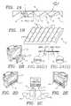
- FIG. 1Ais a top view of a microprism sheet arranged to emulate privacy screen in accordance with the principles of a first preferred embodiment of the invention, in which x and y are horizontal axes respectively extending parallel to and perpendicular to the principal plane of the microprism sheet.
- FIG. 1Bis an isometric view of the microprism sheet of FIG. 1A
- FIG. 2Ais a top view of a two-player game application of the microprism sheet of FIGS. 1A and 1B.
- FIG. 2Ban isometric view showing the manner in which the microprism sheet of FIG. 2A is arranged on a computer monitor or television.
- FIG. 2Cis a schematic diagram illustrating the operation of the two-player game application shown in FIGS. 2A and 2B.
- FIGS. 2D and 2Eare isometric views further illustrating the operation of the two-player game application shown in FIGS. 2A and 2B.
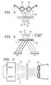
- FIG. 3is a schematic diagram illustrating a microprism sheet arranged to separate an image and provide a stereoscopic effect according to the principles of a second preferred embodiment of the invention.
- FIG. 4is a schematic diagram illustrating a microprism sheet arranged to interlace separate images and provide a stereoscopic effect according to the principles of a third preferred embodiment of the invention.
- FIG. 5is a schematic diagram illustrating an application of the image interlacing arrangement of FIG. 4 .
- FIGS. 1A and 1Billustrate the manner in which a microprism sheet 1 , which is of the type having v-shaped linear grooves 2 defined by surfaces 3 and 4 extending at respective angles ⁇ and ⁇ relative to an axis Y transverse to the principal plane of sheet 1 , is arranged to emulate a privacy screen according to the principles of a first preferred embodiment of the invention.
- privacy screen emulationis obtained by modifying surfaces 3 so as to attenuate or scatter light transmitted therethrough.
- microprism sheet 1may be of conventional construction and materials. Modification of surfaces 3 can be carried out by any of the methods described in the prior patents cited above, including coating the surfaces with an opaque material and casting irregularities into the surfaces, or the surfaces may be modified by delustering, and/or chemical or laser etching. In the case of chemical or laser etching, surfaces may be made opaque by roughening, either by applying the chemical or directing the laser at the surface through an appropriate mask, or by etching the casting tool or die that forms the sheet.
- surfaces originally cast with texturing or a satin finishcould be polished to permit transmission of light, as could the planar rear surface of the microprism sheet, in which case the “altered” surfaces would be the light transmitting surfaces, or an additional printed black-and-white or color image could be applied to the light attenuating surfaces so that the person viewing the privacy screen would see the printed image rather than the image transmitted through the microprism sheet.
- the pitch of the grooves and angles of the respective planeswill depend on the particular application. However, those skilled in the art will appreciate that the smaller the pitch, the less visible the grooves, for a smoother appearance.
- the angles at which viewing is optimal and/or at which a viewer will be unable to perceive an imagewill of course depend on the exact angles ⁇ and ⁇ of surfaces 3 and 4 and the index of refraction of the material from which microprism sheet 1 is constructed.
- angle ais set at between 45° and 60°
- angle ⁇is set at between 45° and 30° relative to axis Y.
- a privacy screen effectcan be achieved with- a microprism sheet having a pitch of 0.13 inches, an angle ⁇ of 20°, and an angle ⁇ of 40° (i.e. 50° from the plane of the sheet)
- the difference between the microprism sheets disclosed by Pugsley and Ohtani and that of the preferred embodimentis that the altered surfaces of the microprism sheets of Pugsley and Ohtani are horizontal surfaces oriented so as not to affect transmission of the image to any potential viewer, whereas the altered surfaces of the microprism sheets of the preferred embodiment are visible to anyone situated outside a relatively narrow range of angles within which the transmitted image is intended to be viewed. Except for the orientation of the altered surfaces, the construction of the privacy screen of this embodiment may be similar to that used in the anti-glare screens of Pugsley and Ohtani.
- FIG. 1Billustrates the v-shaped grooves as being both linear and parallel
- FIG. 1Billustrates the v-shaped grooves as being both linear and parallel
- FIG. 1Billustrates the v-shaped grooves as being both linear and parallel
- those skilled in the artwill recognize that it is possible to provide a privacy-screening microprism sheet having grooves that curve, so as to extend the screening effect to three dimensions.
- Such an arrangementwould not only frustrate eavesdroppers positioned to the right or left of a person viewing an image on the screen, but also prevent eavesdropping from above or below the person.
- the microprism sheetmay be arranged such that one portion 6 of the sheet is arranged to screen an image in one direction and a second portion 7 of the sheet is arranged to screen an image in a second direction.
- the grooves 8 and 9 of respective portions 6 and 7 of the microprism sheethave light attenuating or scattering surfaces 10 , 11 oriented to prevent transmission of light to persons positioned on opposite sides of a plane bisecting the microprism sheet, and corresponding light transmitting surfaces that direct transmitted light to the appropriate positions.
- portionsmay refer to physically discrete sheets having respective grooves oriented in different directions and which are either joined together or simply located in close proximity to each other, rather than a single sheet having grooves oriented in different directions.
- the microprism sheet of this variation of the first preferred embodiment of the inventionmay be arranged as an overlay 12 for part or all of the screen of a computer monitor or television 13 , as shown in FIG. 2B, and is especially suitable for use in connection with a two-player video game, as illustrated in FIGS. 2C-2E.
- portion 6 of the microprism sheet illustrated in FIG. 2Ais arranged to direct the first image 14 on the left side of the screen to first player 15 while screening image 14 from the second player 16 .
- the portion 7 of the microprism sheet of the variation of the first preferred embodiment illustrated in FIG. 3Ais arranged to direct a second image 17 to second player 16 while screening image 17 from first player 15 .
- FIG. 3A variation of the concept of altering one of the surfaces of a microprism sheet to create a privacy screen is illustrated in FIG. 3 .
- surfaces 20 and 21 corresponding to surfaces 3 and 4 of the embodiment illustrated in FIG. 1are altered to polarize light in opposite directions, and to direct the polarized light towards corresponding oppositely polarized eyeglass lenses 22 and 23 .
- lens 22will only pass light transmitted at a first angle by surfaces 21
- lens 23will only pass light transmitted at a second angle by surfaces 20 , then so long as the pitch of the grooves corresponds to the pitch of left and right channel interlaced image sections 24 and 25 , image sections 24 and 25 will be transmitted through the appropriate surfaces 20 and 21 , and an enhanced stereoscopic effect can be obtained in an especially simple manner.
- One advantage of this arrangementis that a person wearing the polarized lenses 22 and 23 , made possible by the use of a microprism sheet including polarizing surfaces 20 and 21 , will be able to view other objects or persons without having to take off the lenses, which is not the case with conventional stereoscopic effects lenses that rely on different colors to separate channels.
- the stereoscopic effectwill be “magically” created by what appears to be a completely transparent screen overlay and ordinary glass lenses.
- a microprism sheetis arranged such that light from a first image 24 ′ is refracted by surfaces 26 and light from a second image 25 ′ is refracted by surfaces 27 to form a single interlaced image 24 , 25 .
- the angles of surfaces 26 and 27are selected based on the relative positions of the separate images, which originate from a split screen or separate screens, and on the desired positions of the interlaced images. Although illustrated as being oriented at non-zero angles, those skilled in the art will appreciate that the surfaces in this embodiment could be arranged to include a transverse surface such that only one of the separate images to be interlaced is refracted.
- One application of the arrangement of the third preferred embodiment of the inventionis to interlace images for use in connection with the stereoscopic effects sheet of FIG. 3 .
- the interlaced image, 24 , 25could be arranged to project in the same plane or in different planes.
- the image sourcesare polarize in opposite directions or otherwise differentiated, for example by opposite direction polarizes 30 and 31
- the imagescan be interlaced by a microprism sheet such as sheet 32 to form a combined image suitable for direct stereoscopic viewing through conventional stereoscopic eyeglass lenses 33 .
- the imagescan even be combined to form as stereoscopic image viewable without the need for special lenses.
- the arrangement of the third preferred embodimentcould simply be used to combine normally separated images, for example to add a changing foreground to a fixed background, to permit the addition of foreground characters to a pre-recorded background, or to permit closed captions or subtitles to be added at the point-of-display rather than at the broadcast location or during recording.
Landscapes
- Engineering & Computer Science (AREA)
- Multimedia (AREA)
- Signal Processing (AREA)
- Physics & Mathematics (AREA)
- General Physics & Mathematics (AREA)
- Optics & Photonics (AREA)
- Overhead Projectors And Projection Screens (AREA)
- Optical Elements Other Than Lenses (AREA)
Abstract
Description
Claims (5)
Priority Applications (5)
| Application Number | Priority Date | Filing Date | Title |
|---|---|---|---|
| US09/481,942US6504649B1 (en) | 2000-01-13 | 2000-01-13 | Privacy screens and stereoscopic effects devices utilizing microprism sheets |
| US09/729,079US20010015753A1 (en) | 2000-01-13 | 2000-12-05 | Split image stereoscopic system and method |
| PCT/US2001/000006WO2001051980A1 (en) | 2000-01-13 | 2001-01-12 | Privacy screens and stereoscopic effects devices utilizing microprism sheets |
| AU2001230842AAU2001230842A1 (en) | 2000-01-13 | 2001-01-12 | Privacy screens and stereoscopic effects devices utilizing microprism sheets |
| US10/054,896US20020089744A1 (en) | 2000-01-13 | 2002-01-25 | Masked split image stereoscopic system and method |
Applications Claiming Priority (1)
| Application Number | Priority Date | Filing Date | Title |
|---|---|---|---|
| US09/481,942US6504649B1 (en) | 2000-01-13 | 2000-01-13 | Privacy screens and stereoscopic effects devices utilizing microprism sheets |
Related Child Applications (1)
| Application Number | Title | Priority Date | Filing Date |
|---|---|---|---|
| US53873100AContinuation-In-Part | 2000-01-13 | 2000-03-30 |
Publications (1)
| Publication Number | Publication Date |
|---|---|
| US6504649B1true US6504649B1 (en) | 2003-01-07 |
Family
ID=23914008
Family Applications (1)
| Application Number | Title | Priority Date | Filing Date |
|---|---|---|---|
| US09/481,942Expired - Fee RelatedUS6504649B1 (en) | 2000-01-13 | 2000-01-13 | Privacy screens and stereoscopic effects devices utilizing microprism sheets |
Country Status (3)
| Country | Link |
|---|---|
| US (1) | US6504649B1 (en) |
| AU (1) | AU2001230842A1 (en) |
| WO (1) | WO2001051980A1 (en) |
Cited By (31)
| Publication number | Priority date | Publication date | Assignee | Title |
|---|---|---|---|---|
| US20020196249A1 (en)* | 2001-06-21 | 2002-12-26 | Peters Paul F. | System of processing and printing multidimensional and motion images from medical data sets |
| US6597328B1 (en)* | 2000-08-16 | 2003-07-22 | International Business Machines Corporation | Method for providing privately viewable data in a publically viewable display |
| US20030159364A1 (en)* | 2002-02-28 | 2003-08-28 | The Nasher Foundation | Light transmission system and method for buildings |
| US20050254129A1 (en)* | 2004-05-13 | 2005-11-17 | Roy Clark | Optical element for efficient sensing at large angles of incidence |
| US20060094510A1 (en)* | 2004-10-19 | 2006-05-04 | Risso Marcus L | Visual barrier for partitioning a viewing area |
| US20060145942A1 (en)* | 2005-01-06 | 2006-07-06 | Nokia Corporation | Extended display device |
| US20060172788A1 (en)* | 2005-01-31 | 2006-08-03 | Screenlife, Llc | Response time-based scoring on DVD players |
| WO2006056939A3 (en)* | 2004-11-24 | 2006-09-14 | Koninkl Philips Electronics Nv | Privacy overlay for interactive display tables |
| US20060227427A1 (en)* | 2003-09-22 | 2006-10-12 | Gene Dolgoff | Omnidirectional lenticular and barrier-grid image displays and methods for making them |
| US20070047262A1 (en)* | 2005-08-27 | 2007-03-01 | 3M Innovative Properties Company | Edge-lit backlight having light recycling cavity with concave transflector |
| US20070047228A1 (en)* | 2005-08-27 | 2007-03-01 | 3M Innovative Properties Company | Methods of forming direct-lit backlights having light recycling cavity with concave transflector |
| US20070047254A1 (en)* | 2005-08-27 | 2007-03-01 | 3M Innovative Properties Company | Illumination assembly and system |
| US20070047261A1 (en)* | 2005-08-27 | 2007-03-01 | Thompson David S | Direct-lit backlight having light recycling cavity with concave transflector |
| US20070087803A1 (en)* | 2002-05-14 | 2007-04-19 | Screenlife, Llc | Game in which clips are stored on a dvd and played during the course of the game |
| US20070127320A1 (en)* | 2005-09-22 | 2007-06-07 | Screenlife, Llc | Device for educational entertainment |
| US20080088935A1 (en)* | 2006-10-17 | 2008-04-17 | Daly Scott J | Methods and Systems for Multi-View Display Privacy |
| US20080194331A1 (en)* | 2007-02-13 | 2008-08-14 | Screenlife, Llc | Displaying information to a selected player in a multi-player game on a commonly viewed display device |
| US20080303807A1 (en)* | 2007-04-19 | 2008-12-11 | Seiko Epson Corporation | Determining apparatus and method for controlling the same |
| US20090040236A1 (en)* | 2007-08-06 | 2009-02-12 | Childress Rhonda L | Method of and System for Preventing Viewing by Bystanders of Information |
| US20100062846A1 (en)* | 2008-09-05 | 2010-03-11 | Eric Gustav Orlinsky | Method and System for Multiplayer Multifunctional Electronic Surface Gaming Apparatus |
| US20100127077A1 (en)* | 2008-11-26 | 2010-05-27 | Toshiba Tec Kabushiki Kaisha | Commodity sales data processing apparatus and control method therefor |
| US20100199577A1 (en)* | 2004-01-08 | 2010-08-12 | Pieter Jan Sonneveld | Cover for an object using solar radiation |
| US20110018901A1 (en)* | 2009-07-27 | 2011-01-27 | Disney Enterprises Inc. | System and method for forming a composite image in a portable computing device having a dual screen display |
| US20120081520A1 (en)* | 2010-10-04 | 2012-04-05 | Samsung Electronics Co., Ltd. | Apparatus and method for attenuating stereoscopic sense of stereoscopic image |
| US20120223884A1 (en)* | 2011-03-01 | 2012-09-06 | Qualcomm Incorporated | System and method to display content |
| WO2012153967A3 (en)* | 2011-05-09 | 2013-01-03 | Oh Seung Tae | Privacy film |
| DE102011052802A1 (en)* | 2011-08-18 | 2013-02-21 | Sick Ag | 3D camera and method for monitoring a room area |
| US8608550B1 (en)* | 2010-11-12 | 2013-12-17 | Wms Gaming, Inc | Coordinating three dimensional wagering game content presentations |
| US8784206B1 (en) | 2011-04-15 | 2014-07-22 | Wms Gaming, Inc. | Modifying presentation of three-dimensional, wagering-game content |
| CN105319615A (en)* | 2014-08-05 | 2016-02-10 | 鸿富锦精密工业(深圳)有限公司 | Display device |
| US20160363778A1 (en)* | 2014-08-15 | 2016-12-15 | Boe Technology Group Co., Ltd. | Grating, Manufacturing Method Thereof and Display Device |
Families Citing this family (3)
| Publication number | Priority date | Publication date | Assignee | Title |
|---|---|---|---|---|
| US7857700B2 (en)* | 2003-09-12 | 2010-12-28 | Igt | Three-dimensional autostereoscopic image display for a gaming apparatus |
| ITNA20110029A1 (en)* | 2011-07-04 | 2013-01-05 | Pietrangelo Gregorio | THREE-DIMENSIONAL TELEVISION SYSTEM, WITH TWO STEREO IMAGES (LEFT-RIGHT) SIDE-BY-SIDE, SHOOTING WITH COMMON CAMERAS EQUIPPED WITH PARTICULAR DEVICES, WITH 3D RECEPTION THROUGH NORMAL TELEVISIONS, WITHOUT MAKING ANY CHANGE TO THE STE |
| CN110189630B (en)* | 2018-02-22 | 2021-11-02 | 诚屏科技股份有限公司 | Multi-screen display device and display method |
Citations (33)
| Publication number | Priority date | Publication date | Assignee | Title |
|---|---|---|---|---|
| US2881686A (en) | 1953-10-10 | 1959-04-14 | Zeiss Ikon A G Stuttgart | Focusing plate for photographic cameras |
| US2909770A (en) | 1953-11-25 | 1959-10-20 | Gen Electric | Transmission screen |
| US3258590A (en)* | 1966-06-28 | Plates for light control | ||
| US3279340A (en) | 1964-03-19 | 1966-10-18 | Rca Corp | Art of making color-phosphor mosaic screens |
| US3718078A (en) | 1970-12-31 | 1973-02-27 | Polaroid Corp | Smoothly granulated optical surface and method for making same |
| US3902787A (en) | 1974-04-17 | 1975-09-02 | Action Films | Rear projection viewing screen |
| US3971051A (en) | 1973-06-29 | 1976-07-20 | Polaroid Corporation | Focusing screen |
| US4165920A (en) | 1977-07-27 | 1979-08-28 | Qantix Corporation | Echo reduction improvement in a front face glare reduction overlay |
| US4206969A (en) | 1979-04-11 | 1980-06-10 | Minnesota Mining And Manufacturing Company | Directional front projection screen |
| US4309074A (en) | 1977-11-28 | 1982-01-05 | Granieri Jr Michael S | Novel viewing screen |
| US4309073A (en) | 1979-01-17 | 1982-01-05 | Sanyo Electric Co., Ltd. | Translucent screen assembly |
| US4333707A (en) | 1979-04-23 | 1982-06-08 | West Laurice J | Method of image enhancement |
| US4588259A (en)* | 1984-07-31 | 1986-05-13 | Bright & Morning Star Company | Stereoscopic optical system |
| US4708435A (en) | 1986-10-30 | 1987-11-24 | Mitsubishi Rayon Co., Ltd. | Rear projection screen |
| US4756603A (en) | 1986-01-31 | 1988-07-12 | Nippon Seiki Co., Ltd. | Glare-proof transparent cover plate |
| US4911529A (en) | 1988-05-27 | 1990-03-27 | U.S. Philips Corporation | Front projection screen |
| US5208620A (en) | 1988-10-04 | 1993-05-04 | Canon Kabushiki Kaisha | Display apparatus |
| US5317405A (en) | 1991-03-08 | 1994-05-31 | Nippon Telegraph And Telephone Corporation | Display and image capture apparatus which enables eye contact |
| US5316359A (en) | 1993-03-08 | 1994-05-31 | Chrysler Corporation | Anti-reflective automotive interior instrument panel surface |
| US5359691A (en) | 1992-10-08 | 1994-10-25 | Briteview Technologies | Backlighting system with a multi-reflection light injection system and using microprisms |
| US5363237A (en) | 1991-11-05 | 1994-11-08 | Masayuki Wakatake | Pseudo-luminous panel, substrate therefor, and display element and device using the pseudo-luminous panel |
| US5446594A (en) | 1992-12-21 | 1995-08-29 | Minnesota Mining And Manufacturing Company | Catadioptric Fresnel lens |
| US5512219A (en) | 1994-06-03 | 1996-04-30 | Reflexite Corporation | Method of casting a microstructure sheet having an array of prism elements using a reusable polycarbonate mold |
| US5600455A (en)* | 1994-08-31 | 1997-02-04 | Enplas Corporation | Prismatic member with coarsened portions or triangular prismatic and semi-circular prismatic members arranged on a flat light emitting surface |
| US5663831A (en)* | 1994-02-23 | 1997-09-02 | Sanyo Electric Co., Ltd. | Three-dimensional display |
| US5729387A (en) | 1899-02-17 | 1998-03-17 | Sanyo Electric Co., Ltd. | Solar lighting apparatus and controller for controlling the solar lighting apparatus |
| US5742411A (en) | 1996-04-23 | 1998-04-21 | Advanced Deposition Technologies, Inc. | Security hologram with covert messaging |
| US5835661A (en) | 1994-10-19 | 1998-11-10 | Tai; Ping-Kaung | Light expanding system for producing a linear or planar light beam from a point-like light source |
| US5837346A (en) | 1995-11-27 | 1998-11-17 | Nashua Corporation | Projection screens having light collimating and light diffusing properties |
| US5836096A (en) | 1996-03-04 | 1998-11-17 | Brauer; William R. | Apparatus for illuminating medical diagnostic imaging film with enhanced viewability |
| US5896225A (en)* | 1993-05-24 | 1999-04-20 | Deutsche Thomson Brandt Gmbh | Device for stereoscopic image observation within an increased observation area |
| US5900972A (en)* | 1995-12-11 | 1999-05-04 | Thomson Multimedia S.A. | Stereoscopic display system |
| US5926601A (en) | 1996-05-02 | 1999-07-20 | Briteview Technologies, Inc. | Stacked backlighting system using microprisms |
- 2000
- 2000-01-13USUS09/481,942patent/US6504649B1/ennot_activeExpired - Fee Related
- 2001
- 2001-01-12WOPCT/US2001/000006patent/WO2001051980A1/enactiveApplication Filing
- 2001-01-12AUAU2001230842Apatent/AU2001230842A1/ennot_activeAbandoned
Patent Citations (33)
| Publication number | Priority date | Publication date | Assignee | Title |
|---|---|---|---|---|
| US3258590A (en)* | 1966-06-28 | Plates for light control | ||
| US5729387A (en) | 1899-02-17 | 1998-03-17 | Sanyo Electric Co., Ltd. | Solar lighting apparatus and controller for controlling the solar lighting apparatus |
| US2881686A (en) | 1953-10-10 | 1959-04-14 | Zeiss Ikon A G Stuttgart | Focusing plate for photographic cameras |
| US2909770A (en) | 1953-11-25 | 1959-10-20 | Gen Electric | Transmission screen |
| US3279340A (en) | 1964-03-19 | 1966-10-18 | Rca Corp | Art of making color-phosphor mosaic screens |
| US3718078A (en) | 1970-12-31 | 1973-02-27 | Polaroid Corp | Smoothly granulated optical surface and method for making same |
| US3971051A (en) | 1973-06-29 | 1976-07-20 | Polaroid Corporation | Focusing screen |
| US3902787A (en) | 1974-04-17 | 1975-09-02 | Action Films | Rear projection viewing screen |
| US4165920A (en) | 1977-07-27 | 1979-08-28 | Qantix Corporation | Echo reduction improvement in a front face glare reduction overlay |
| US4309074A (en) | 1977-11-28 | 1982-01-05 | Granieri Jr Michael S | Novel viewing screen |
| US4309073A (en) | 1979-01-17 | 1982-01-05 | Sanyo Electric Co., Ltd. | Translucent screen assembly |
| US4206969A (en) | 1979-04-11 | 1980-06-10 | Minnesota Mining And Manufacturing Company | Directional front projection screen |
| US4333707A (en) | 1979-04-23 | 1982-06-08 | West Laurice J | Method of image enhancement |
| US4588259A (en)* | 1984-07-31 | 1986-05-13 | Bright & Morning Star Company | Stereoscopic optical system |
| US4756603A (en) | 1986-01-31 | 1988-07-12 | Nippon Seiki Co., Ltd. | Glare-proof transparent cover plate |
| US4708435A (en) | 1986-10-30 | 1987-11-24 | Mitsubishi Rayon Co., Ltd. | Rear projection screen |
| US4911529A (en) | 1988-05-27 | 1990-03-27 | U.S. Philips Corporation | Front projection screen |
| US5208620A (en) | 1988-10-04 | 1993-05-04 | Canon Kabushiki Kaisha | Display apparatus |
| US5317405A (en) | 1991-03-08 | 1994-05-31 | Nippon Telegraph And Telephone Corporation | Display and image capture apparatus which enables eye contact |
| US5363237A (en) | 1991-11-05 | 1994-11-08 | Masayuki Wakatake | Pseudo-luminous panel, substrate therefor, and display element and device using the pseudo-luminous panel |
| US5359691A (en) | 1992-10-08 | 1994-10-25 | Briteview Technologies | Backlighting system with a multi-reflection light injection system and using microprisms |
| US5446594A (en) | 1992-12-21 | 1995-08-29 | Minnesota Mining And Manufacturing Company | Catadioptric Fresnel lens |
| US5316359A (en) | 1993-03-08 | 1994-05-31 | Chrysler Corporation | Anti-reflective automotive interior instrument panel surface |
| US5896225A (en)* | 1993-05-24 | 1999-04-20 | Deutsche Thomson Brandt Gmbh | Device for stereoscopic image observation within an increased observation area |
| US5663831A (en)* | 1994-02-23 | 1997-09-02 | Sanyo Electric Co., Ltd. | Three-dimensional display |
| US5512219A (en) | 1994-06-03 | 1996-04-30 | Reflexite Corporation | Method of casting a microstructure sheet having an array of prism elements using a reusable polycarbonate mold |
| US5600455A (en)* | 1994-08-31 | 1997-02-04 | Enplas Corporation | Prismatic member with coarsened portions or triangular prismatic and semi-circular prismatic members arranged on a flat light emitting surface |
| US5835661A (en) | 1994-10-19 | 1998-11-10 | Tai; Ping-Kaung | Light expanding system for producing a linear or planar light beam from a point-like light source |
| US5837346A (en) | 1995-11-27 | 1998-11-17 | Nashua Corporation | Projection screens having light collimating and light diffusing properties |
| US5900972A (en)* | 1995-12-11 | 1999-05-04 | Thomson Multimedia S.A. | Stereoscopic display system |
| US5836096A (en) | 1996-03-04 | 1998-11-17 | Brauer; William R. | Apparatus for illuminating medical diagnostic imaging film with enhanced viewability |
| US5742411A (en) | 1996-04-23 | 1998-04-21 | Advanced Deposition Technologies, Inc. | Security hologram with covert messaging |
| US5926601A (en) | 1996-05-02 | 1999-07-20 | Briteview Technologies, Inc. | Stacked backlighting system using microprisms |
Cited By (61)
| Publication number | Priority date | Publication date | Assignee | Title |
|---|---|---|---|---|
| US6597328B1 (en)* | 2000-08-16 | 2003-07-22 | International Business Machines Corporation | Method for providing privately viewable data in a publically viewable display |
| US20020196249A1 (en)* | 2001-06-21 | 2002-12-26 | Peters Paul F. | System of processing and printing multidimensional and motion images from medical data sets |
| US7222461B2 (en) | 2002-02-28 | 2007-05-29 | The Nasher Foundation | Light transmission system and method for buildings |
| US20030159364A1 (en)* | 2002-02-28 | 2003-08-28 | The Nasher Foundation | Light transmission system and method for buildings |
| WO2003072887A1 (en)* | 2002-02-28 | 2003-09-04 | The Nasher Foundation | Light transmission system and method for buildings |
| US8287342B2 (en) | 2002-05-14 | 2012-10-16 | Screenlife, Llc | Media containing puzzles in the form of clips |
| US20070155459A1 (en)* | 2002-05-14 | 2007-07-05 | Screenlife, Llc | Media containing puzzles in the form of clips |
| US20110070937A1 (en)* | 2002-05-14 | 2011-03-24 | Screenlife, Llc | Media containing puzzles in the form of clips |
| US7857692B2 (en) | 2002-05-14 | 2010-12-28 | Screenlife, Llc | Media containing puzzles in the form of clips |
| US8366529B2 (en) | 2002-05-14 | 2013-02-05 | Screenlife, Llc | Game in which clips are stored on a DVD and played during the course of the game |
| US20070087803A1 (en)* | 2002-05-14 | 2007-04-19 | Screenlife, Llc | Game in which clips are stored on a dvd and played during the course of the game |
| US20060227427A1 (en)* | 2003-09-22 | 2006-10-12 | Gene Dolgoff | Omnidirectional lenticular and barrier-grid image displays and methods for making them |
| US7457038B2 (en)* | 2003-09-22 | 2008-11-25 | Gene Dolgoff | Omnidirectional lenticular and barrier-grid image displays and methods for making them |
| US20100199577A1 (en)* | 2004-01-08 | 2010-08-12 | Pieter Jan Sonneveld | Cover for an object using solar radiation |
| US7102824B2 (en) | 2004-05-13 | 2006-09-05 | The Boeing Company | Optical element for efficient sensing at large angles of incidence |
| US20050254129A1 (en)* | 2004-05-13 | 2005-11-17 | Roy Clark | Optical element for efficient sensing at large angles of incidence |
| US20060094510A1 (en)* | 2004-10-19 | 2006-05-04 | Risso Marcus L | Visual barrier for partitioning a viewing area |
| US20090174670A1 (en)* | 2004-11-24 | 2009-07-09 | Koninklijke Philips Electronics, N.V. | Placement for interactive display tables |
| JP2008521048A (en)* | 2004-11-24 | 2008-06-19 | コーニンクレッカ フィリップス エレクトロニクス エヌ ヴィ | Placemat for interactive display table |
| US8487880B2 (en)* | 2004-11-24 | 2013-07-16 | Koninklijke Philips Electronics N.V. | Placement for interactive display tables |
| WO2006056939A3 (en)* | 2004-11-24 | 2006-09-14 | Koninkl Philips Electronics Nv | Privacy overlay for interactive display tables |
| US7551148B2 (en)* | 2005-01-06 | 2009-06-23 | Nokia Corporation | Extended display device |
| US20060145942A1 (en)* | 2005-01-06 | 2006-07-06 | Nokia Corporation | Extended display device |
| US20060172788A1 (en)* | 2005-01-31 | 2006-08-03 | Screenlife, Llc | Response time-based scoring on DVD players |
| US20070047261A1 (en)* | 2005-08-27 | 2007-03-01 | Thompson David S | Direct-lit backlight having light recycling cavity with concave transflector |
| US7537374B2 (en) | 2005-08-27 | 2009-05-26 | 3M Innovative Properties Company | Edge-lit backlight having light recycling cavity with concave transflector |
| US20070047228A1 (en)* | 2005-08-27 | 2007-03-01 | 3M Innovative Properties Company | Methods of forming direct-lit backlights having light recycling cavity with concave transflector |
| US20070047254A1 (en)* | 2005-08-27 | 2007-03-01 | 3M Innovative Properties Company | Illumination assembly and system |
| US20070047262A1 (en)* | 2005-08-27 | 2007-03-01 | 3M Innovative Properties Company | Edge-lit backlight having light recycling cavity with concave transflector |
| US7695180B2 (en) | 2005-08-27 | 2010-04-13 | 3M Innovative Properties Company | Illumination assembly and system |
| US20110025947A1 (en)* | 2005-08-27 | 2011-02-03 | 3M Innovative Properties Company | Direct-lit backlight having light recycling cavity with concave transflector |
| US9857518B2 (en) | 2005-08-27 | 2018-01-02 | 3M Innovative Properties Company | Direct-lit backlight having light recycling cavity with concave transflector |
| US7815355B2 (en) | 2005-08-27 | 2010-10-19 | 3M Innovative Properties Company | Direct-lit backlight having light recycling cavity with concave transflector |
| US20070127320A1 (en)* | 2005-09-22 | 2007-06-07 | Screenlife, Llc | Device for educational entertainment |
| US7762676B2 (en)* | 2006-10-17 | 2010-07-27 | Sharp Laboratories Of America, Inc. | Methods and systems for multi-view display privacy |
| US20080088935A1 (en)* | 2006-10-17 | 2008-04-17 | Daly Scott J | Methods and Systems for Multi-View Display Privacy |
| US20080194331A1 (en)* | 2007-02-13 | 2008-08-14 | Screenlife, Llc | Displaying information to a selected player in a multi-player game on a commonly viewed display device |
| US7892095B2 (en)* | 2007-02-13 | 2011-02-22 | Screenlife, Llc | Displaying information to a selected player in a multi-player game on a commonly viewed display device |
| US8111252B2 (en)* | 2007-04-19 | 2012-02-07 | Seiko Epson Corporation | Determining apparatus and method for controlling the same |
| US20080303807A1 (en)* | 2007-04-19 | 2008-12-11 | Seiko Epson Corporation | Determining apparatus and method for controlling the same |
| US8026930B2 (en)* | 2007-08-06 | 2011-09-27 | International Business Machines Corporation | Preventing viewing by bystanders of information on a display screen |
| US20090040236A1 (en)* | 2007-08-06 | 2009-02-12 | Childress Rhonda L | Method of and System for Preventing Viewing by Bystanders of Information |
| US8540569B2 (en) | 2008-09-05 | 2013-09-24 | Eric Gustav Orlinsky | Method and system for multiplayer multifunctional electronic surface gaming apparatus |
| US20100062846A1 (en)* | 2008-09-05 | 2010-03-11 | Eric Gustav Orlinsky | Method and System for Multiplayer Multifunctional Electronic Surface Gaming Apparatus |
| US8322611B2 (en)* | 2008-11-26 | 2012-12-04 | Toshiba Tec Kabushiki Kaisha | Commodity sales data processing apparatus and control method therefor |
| US20100127077A1 (en)* | 2008-11-26 | 2010-05-27 | Toshiba Tec Kabushiki Kaisha | Commodity sales data processing apparatus and control method therefor |
| US8847984B2 (en) | 2009-07-27 | 2014-09-30 | Disney Enterprises, Inc. | System and method for forming a composite image in a portable computing device having a dual screen display |
| US20110018901A1 (en)* | 2009-07-27 | 2011-01-27 | Disney Enterprises Inc. | System and method for forming a composite image in a portable computing device having a dual screen display |
| US20120081520A1 (en)* | 2010-10-04 | 2012-04-05 | Samsung Electronics Co., Ltd. | Apparatus and method for attenuating stereoscopic sense of stereoscopic image |
| US9225960B2 (en)* | 2010-10-04 | 2015-12-29 | Samsung Electronics Co., Ltd. | Apparatus and method for attenuating stereoscopic sense of stereoscopic image |
| US8608550B1 (en)* | 2010-11-12 | 2013-12-17 | Wms Gaming, Inc | Coordinating three dimensional wagering game content presentations |
| US9285883B2 (en)* | 2011-03-01 | 2016-03-15 | Qualcomm Incorporated | System and method to display content based on viewing orientation |
| US20120223884A1 (en)* | 2011-03-01 | 2012-09-06 | Qualcomm Incorporated | System and method to display content |
| US8784206B1 (en) | 2011-04-15 | 2014-07-22 | Wms Gaming, Inc. | Modifying presentation of three-dimensional, wagering-game content |
| US9292997B2 (en) | 2011-04-15 | 2016-03-22 | Bally Gaming, Inc. | Modifying presentation of three-dimensional, wagering-game content |
| WO2012153967A3 (en)* | 2011-05-09 | 2013-01-03 | Oh Seung Tae | Privacy film |
| DE102011052802A1 (en)* | 2011-08-18 | 2013-02-21 | Sick Ag | 3D camera and method for monitoring a room area |
| DE102011052802B4 (en)* | 2011-08-18 | 2014-03-13 | Sick Ag | 3D camera and method for monitoring a room area |
| CN105319615A (en)* | 2014-08-05 | 2016-02-10 | 鸿富锦精密工业(深圳)有限公司 | Display device |
| US20160363778A1 (en)* | 2014-08-15 | 2016-12-15 | Boe Technology Group Co., Ltd. | Grating, Manufacturing Method Thereof and Display Device |
| US10073274B2 (en)* | 2014-08-15 | 2018-09-11 | Boe Technology Group Co., Ltd. | Grating, manufacturing method thereof and display device |
Also Published As
| Publication number | Publication date |
|---|---|
| WO2001051980A1 (en) | 2001-07-19 |
| AU2001230842A1 (en) | 2001-07-24 |
Similar Documents
| Publication | Publication Date | Title |
|---|---|---|
| US6504649B1 (en) | Privacy screens and stereoscopic effects devices utilizing microprism sheets | |
| EP2788809B1 (en) | Compact illumination module for head mounted display | |
| JP4509978B2 (en) | Lighting system and display equipped with the same | |
| US5671992A (en) | Stereoscopic display unit | |
| US6999665B2 (en) | Display panel having dual directional diffusion | |
| US9715117B2 (en) | Autostereoscopic three dimensional display | |
| US8459797B2 (en) | Image viewing systems with an integrated screen lens | |
| US8746876B2 (en) | Stereoscopic eyewear with stray light management | |
| WO2013069589A1 (en) | Reflective screen and projection display device provided with same | |
| AU777830B2 (en) | Projection system | |
| US4333707A (en) | Method of image enhancement | |
| TWI428632B (en) | Three-dimensional image display | |
| JP4747408B2 (en) | Screen and 3D display system using it | |
| WO2012150703A1 (en) | Video display system, projection display device, directional reflection screen and layer display device | |
| JPWO2002025369A1 (en) | Image display device | |
| KR20190130702A (en) | Multi-display device having screen structure for uniform illumination | |
| US20020089744A1 (en) | Masked split image stereoscopic system and method | |
| WO2001084212A1 (en) | Improved microprism sheets and privacy screens utilizing same | |
| JP5397911B2 (en) | Reflective recursive front screen and reflective stereoscopic display screen | |
| CN112399169A (en) | Projection array type naked-eye 3D display system | |
| CA2404985A1 (en) | Split image stereoscopic system and method | |
| CN108469715A (en) | A kind of display methods based on the projection of pixel light source microarray | |
| CN208257977U (en) | A kind of display system based on the projection of pixel light source microarray | |
| CA1170872A (en) | Image enhancement | |
| JPH07199382A (en) | Stereoscopic display |
Legal Events
| Date | Code | Title | Description |
|---|---|---|---|
| AS | Assignment | Owner name:MYERS, KENNETH J., NEW YORK Free format text:ASSIGNMENT OF ASSIGNORS INTEREST;ASSIGNOR:MYERS, KENNETH J.;REEL/FRAME:010708/0431 Effective date:20000413 Owner name:GREENBERG, EDWARD, NEW YORK Free format text:ASSIGNMENT OF ASSIGNORS INTEREST;ASSIGNOR:MYERS, KENNETH J.;REEL/FRAME:010708/0431 Effective date:20000413 | |
| AS | Assignment | Owner name:GREENBERG, EDWARD, NEW YORK Free format text:ASSIGNMENT OF ASSIGNORS INTEREST;ASSIGNORS:MYERS, KENNETH J.;GREENBERG, EDWARD;REEL/FRAME:014078/0010 Effective date:20030514 Owner name:PERRY, MICHAEL, NEW YORK Free format text:ASSIGNMENT OF ASSIGNORS INTEREST;ASSIGNORS:MYERS, KENNETH J.;GREENBERG, EDWARD;REEL/FRAME:014078/0010 Effective date:20030514 | |
| REMI | Maintenance fee reminder mailed | ||
| LAPS | Lapse for failure to pay maintenance fees | ||
| STCH | Information on status: patent discontinuation | Free format text:PATENT EXPIRED DUE TO NONPAYMENT OF MAINTENANCE FEES UNDER 37 CFR 1.362 | |
| FP | Lapsed due to failure to pay maintenance fee | Effective date:20070107 |