US6504633B1 - Analog and digital electronic receivers for dual-use wireless data networks - Google Patents
Analog and digital electronic receivers for dual-use wireless data networksDownload PDFInfo
- Publication number
- US6504633B1 US6504633B1US09/292,126US29212699AUS6504633B1US 6504633 B1US6504633 B1US 6504633B1US 29212699 AUS29212699 AUS 29212699AUS 6504633 B1US6504633 B1US 6504633B1
- Authority
- US
- United States
- Prior art keywords
- data
- receiver
- output
- frequency
- bits per
- Prior art date
- Legal status (The legal status is an assumption and is not a legal conclusion. Google has not performed a legal analysis and makes no representation as to the accuracy of the status listed.)
- Expired - Lifetime
Links
Images


Classifications
- H—ELECTRICITY
- H04—ELECTRIC COMMUNICATION TECHNIQUE
- H04B—TRANSMISSION
- H04B10/00—Transmission systems employing electromagnetic waves other than radio-waves, e.g. infrared, visible or ultraviolet light, or employing corpuscular radiation, e.g. quantum communication
- H04B10/11—Arrangements specific to free-space transmission, i.e. transmission through air or vacuum
- H04B10/114—Indoor or close-range type systems
- H04B10/1143—Bidirectional transmission
- H—ELECTRICITY
- H04—ELECTRIC COMMUNICATION TECHNIQUE
- H04B—TRANSMISSION
- H04B10/00—Transmission systems employing electromagnetic waves other than radio-waves, e.g. infrared, visible or ultraviolet light, or employing corpuscular radiation, e.g. quantum communication
- H04B10/11—Arrangements specific to free-space transmission, i.e. transmission through air or vacuum
- H04B10/114—Indoor or close-range type systems
- H04B10/116—Visible light communication
Definitions
- the present inventionrelates to the simultaneous dual use of radiation, e.g., visible light, received from a transmitter, for both a conventional application, e.g., illumination, combined with the additional application of receiving information over a wireless media.
- the present inventionfurther relates to electronic circuits capable of receiving information-bearing transmissions from a “dual use” transmitter and decoding or presenting the information to a user.
- the present inventionfurther relates to the presentation of this data as an audio signal.
- the present inventionfurther relates to the presentation of this data as a text or graphical signal.
- the present inventionfurther relates to the presentation of this data as any digital or analog information signal for another electronic circuit or electronic or electromechanical system.
- the present inventionfurther relates to schemes for efficient receiving and decoding of transmitted signals designed to maximize the bandwidth or information transfer capability of the optical data channel.
- the present inventionfurther relates to the construction of receivers for the detection of modulated information in transmitted light.
- a communication networkis a means for conveying information from one place to another.
- the informationcan be digital data, audio, video, text, graphics, data, sign language, or other forms.
- Establishing and maintaining communication networksis one of the oldest known activities of civilization, ranging from the shouting and drum signals of prehistory through written messages, signal flags, signal fires, smoke signals, signal mirrors, heliographs, signal lanterns, telegraphs, radios, telephones, televisions, microwave signals, linked computers and the internet. Improving communication networks, and finding new, inexpensive ways to meet the growing demand for transmission capability will continue to be a major technical focus in the future. We have developed a communication network that makes “dual use” of sources of radiated transmissions.
- this communication networksuch as a wide bandwidth intranet
- Informationis encoded in the lamp light by modulating the electric lamp current with an information signal. If the modulation is done with care, the lamp continues to emit light with no perceptible visual flicker to the human eye.
- an electronic circuit or receivercan be used to decode information in the transmitted light. The lights continue to serve their primary function as a source of illumination, while simultaneously creating a wireless optical data path for information transmission.
- the purpose of this inventionis to disclose efficient means for creating a receiver that decodes information in the lamp light with the highest possible bandwidth or information carrying capacity over the transmitted channel.
- This inventionis the first to propose establishing a transceiver system using any radiating transmitter with dual utility where the primary utility is any application, not just illumination but also possibly range finding, lane marking, or other applications, and the secondary utility is communication.
- This inventionis the first to propose the transmission of bandlimited analog information such as audio signals by using frequency modulation, which enhances the noise immunity and available bandwidth over previous schemes while specifically avoiding sensory perceptible flicker in the transmission. It is the first to propose the efficient transmission of digital data using pulse code frequency modulation, and also the first to propose encoding digital bits in sidebands around the carrier frequency of the transmitter. It is the first to propose the use of a nonlinear detector in a dual-use network receiver to improve settling and detection time of pulse-coded data.
- the encoding techniqueinvolves chopping 100 microsecond slices of current out of the arc waveform.
- NakadaJapanese Patent application 60-32443, Feb 19, 1985.
- FSKfrequency shift keying
- GrayU.S. Pat. No. 5,635,915 Jun. 3, 1997 and PCT WO90/13067, Oct. 11, 1991.
- PMphase modulated
- This transceiver setrelies on an encoded clock embedded in the three-level, transmitted waveform to synchronize the decoding process in the receiver.
- FMfrequency modulated
- receiversto decode both analog and also digital waveforms from transmitted lamp light. These receivers maximize the available bandwidth of the communication channel. They also incorporate unique and novel features to ensure a variety of desirable features in the receiver.
- the receivercan be designed to provide an indication of “lock-on” to an available transmitter, and can be designed to provide gradual or abrupt fading of the information signal presented to a user as a source becomes available or moves away.
- a gradual acquisitionfor example, could be invaluable in using the transceiver set for direction finding.
- a more abrupt localization of the transmission sourcemay be best in a transmitter-rich environment with many different competing signal sources.
- the transceiverincludes a transmitter for transmitting coded data band limited to avoid visually perceptible flicker by varying the operating frequency of a source of radiation having a primary and secondary utility.
- Visually perceptible flickerwould be considered “application unacceptable” flicker in a dual-use transceiver set employing visible light transmitters.
- Other applicationse.g., a radar set dual-use transmitter, might define application unacceptable flicker in different ways, e.g., flicker that interferes with radar detection.
- “application unacceptable” flickeroccurs when variations due to the secondary utility interfere with the first, or vice-versa.
- the systemincludes a receiver for receiving the encoded radiation, decoding the coded data and delivering the decoded data signal to an output stage.
- the receiverinclude adjustable lock-in characteristics and have a non linear detector to optimize reception performance.
- the receivermay also include internal data storage in which stored data can be cued by signals from the transmitted radiation. It is also preferred that the receiver include an adjustable detector to lock on to different transmitted channels or carrier waves.
- the output stagemay produce an audio output, text output or a graphical output.
- the receivermay also include a split or multi-window graphical output or display for displaying multiple data sources or synchronized data windows, for example, for text and a translation thereof.
- the receivermay include a digital data output or computer interface or have a graphical output or display for presenting sign language. It is also preferred that the data is sideband encoded digital data or orthogonal block frequency code data other than tri-level coding.
- the present inventionpertains, in part, to electronic circuits capable of receiving radiated transmissions, e.g., light from a fluorescent lamp.
- the circuitsfurther include means to sense light.
- the circuitsfurther include means to detect changes in the frequency of the flickering of the light, where this flickering may be invisible to the human eye.
- the circuitsfurther include means to demodulate the flickering to recover a signal from the transmission source.
- the circuitsfurther include means to present this signal as analog data, e.g., an audio signal.
- the circuitsfurther include means to detect discrete levels in the signal, and to decode these levels to reproduce a digital data or bit stream from the transmitter.
- lampa device that produces radiated transmissions, including, but not limited to, infra-red, visible, and ultra-violet light, in response to an input electrical current which flows in the lamp.
- a typical exampleis a fluorescent lamp, although other types, such as high-intensity discharge lamps, light emitting diodes, gas and solid state lasers, particle beam emitters, cathode ray tubes, liquid crystal displays, electroluminescent panels, klystrons, and masers, are also intended.
- Emitters of other types of radiationsuch as radio antennae for applications in RADAR sets, ultrasonic transducers and mechanical blowers (“radiating” air or water, for instance), for example, are also intended.
- transmitteras that term is used herein, it is meant a circuit in combination with a lamp that controls the flicker frequency of the radiated output of the lamp.
- receiverit is meant a circuit that takes as input a radiated transmission from a transmitter and that detects and presents information in the transmission, including, but not limited to, audio, text, graphical, and raw digital data signals.
- sensoran electrical component or sub-circuit in the receiver that is capable of observing and responding to radiated transmissions.
- the sensorcould respond, for example, by providing an electrical signal that varies according to variations in the transmitted radiation.
- amplifieran electrical component or sub-circuit in the receiver that produces a scaled copy of the input waveform at the output of the amplifier.
- the scale factor relating the input and outputis called the gain of the amplifier or simply the gain.
- the amplifiermight include automatic-gain control capability to produce an output with constant mean or peak amplitude in the face of variations in the mean or peak amplitude of the input signal.
- filteran electrical component or sub-circuit in the receiver that produces an output waveform that contains a limited range or band of the frequency content of the input waveform. Typical examples include low, high, and band pass filters.
- detectora component or sub-circuit in the receiver that takes an input signal that consists of a carrier wave modulated by an information signal.
- the carrier wavecould be modulated by any means, including frequency, amplitude, or phase modulation.
- the detectorproduces an output waveform that reproduces the information in the modulating information signal.
- decodera component or sub-circuit in the receiver that takes an input signal that contains information of interest, possibly in an encoded or encrypted form. Encryption could be employed in the transmitted data, to ensure security, and compression might be used to increase the effective data transmission rate.
- the decoderproduces an output electrical waveform that reverses the encoding, e.g., encryption and/or compression, producing, for example, an output waveform consisting of useful binary voltage levels.
- output stageas used herein, it is meant a component or sub-circuit in the receiver that presents information to the user of the receiver in a convenient form. For example, the output stage could incorporate an amplifier and a headset to provide an audio signal of interest to the user.
- the output stagecould take a demodulated and decoded digital information waveform as input and produce a text or graphics display.
- the output stagecould accept commands in the demodulated and decoded input waveform and, in response to these commands, cue the presentation of stored audio, textual, graphical, or other information from a memory, disk, or other storage component in the output stage.
- a transceiver systemis deployed that consists of an optical transmitter and receiver.
- the transmittermodulates the flicker (variations in intensity) frequency of the light output of a fluorescent lamp fixture. Transmission is accomplished by modulating or varying the frequency of the alternating current in the fluorescent lamp.
- the modulating signalis an audio voice recording that has been carefully bandlimited to a frequency range of 200 Hz to 3000 Hz. This ensures that the modulating signal will not create significant harmonic components in a frequency range detectable to the human eye.
- Light from the lampfloods an area, e.g., a room, with illuminating light that is flickering above the human visual perception range, i.e, the lamp light appears steady.
- the optical receiverrecovers information from the light, similar in concept to the way a radio recovers signals from radio waves.
- the receiveris part of a “dual-use” network, in which the light serves not one purpose, as radio waves do in the case of a radio transceiver set, but rather two purposes: illumination and information transmission.
- An optical sensoris employed in the receiver. This sensor is sensitive to light in the infra-red and visible light ranges. The sensor is capable of clearly resolving the flickering of the light, even though the flickering is above the human visual perception range. Note that, if the arc frequency varies over a particular frequency range, e.g., 38 to 40 kHz, the received intensity varies from 76 to 80 kHz because the intensity of the light varies with the magnitude and not the direction of the arc current.
- a selective bandpass filterfollows the output of the sensor. This filter ensures that detected signals in the flicker frequency range are passed, while other frequency components are rejected.
- An amplifiermay be employed before, after, or before and after the filter to condition the detected signal level.
- a phase-locked loop (PLL) circuitcan be employed as a detector to demodulate the FM transmission.
- the output of the loop filter of a properly tuned PLL circuitwill correspond to the modulating information signal at the transmitter.
- This signalis directly useful, requiring no decoding, and can be directly passed to the output stage that consists of an audio amplifier and headset. A user can hear the broadcast audio messages over the headset.
- the modulating signalis restricted to a discrete set of frequencies in sidebands around the carrier frequency, i.e., a fixed base frequency for the lamp current. Different sideband frequencies correspond to different discrete tones.
- the identical sensor, filter, and amplifiercould be used as in the previous embodiment to construct a receiver to detect the transmissions.
- a new detector and decodercould be added to recover the discrete tones, and interpret them as digital bits. These bits could be used to convey text or graphics information to a display, or to send commands to an output stage capable of cueing data for presentation from a storage device integral with the receiver.
- digital bitscould be transmitted using pulse code modulation, in which each “0” or “1” or mark bit corresponds to a specific sequence or pulse code of transmitted frequencies.
- the identical sensor, filter, and amplifiercould be used as in the previous embodiment to construct a receiver to detect the transmissions.
- a PLL circuitcould be used to detect the transmitted frequency levels. If the pulse codes consist of at most two frequency levels, the PLL might be configured to operate nonlinearly, saturating between its high and low frequency loop filter voltage levels, to indicate the transmitted frequency levels.
- the stream of transmitted frequency levelswould be decoded into bits by a decoder circuit, e.g., a finite state machine, programmed to interpret the chosen pulse code as bits.
- these bitscould be used to convey text or graphics information to a display, or to send commands to an output stage capable of cueing data for presentation from a storage device integral with the receiver.
- FIG. 1is a schematic illustration of the transceiver system of the invention.
- FIG. 2is a schematic illustration of a receiver for use in the transceiver system.
- FIG. 3shows a circuit schematic of a receiver capable of recovering transmitted audio information.
- FIG. 4shows a half-weight bit pattern
- FIGS. 5 a and 5 bshow a spectrum comparison showing the advantage of half-weight bit coding.
- FIG. 6shows a receiver architecture for decoding digital data transmitted by the light.
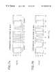
- FIG. 7shows a comparison of sent and received encoded bits in a prototype system.
- the present inventioninvolves a transceiver set in which a transmitter transmits coded data by varying the operating frequency of a source of radiation, e.g., an electric lamp and lamp ballast circuit.
- a source of information 10provides information to a transmitter 11 which generates modulated electromagnetic radiation 12 which, in some embodiments, is visible light.
- the radiation 12may, of course, be radiation in any spectral region.
- a receiver 14responds to the radiation 12 to generate an output which may be audio, text or graphical information. The information is then used by a user of information 15 .
- the receiver 14includes a sensor 16 which responds to the radiation 12 to generate an output signal which forms the input to an amplifier and filter section 18 .
- a detector 20passes a signal to a decoder stage 22 which extracts the information encoded in the radiation 12 and displays it at an output stage 24 .
- the signal to be transmittedis an analog AC signal with a minimum frequency content above that of the human visual perception range for flicker and a maximum frequency content significantly below the nominal switch frequency of the inverter, it is sufficient to apply the signal directly to the frequency modulating input of the ballast. See, U.S. Pat. No. 6,198,230 and entitled “Dual-Use Electronic Transceiver Set for Wireless Data Networks” and application Ser. No. 09/291,709 filed Apr. 14, 1999 entitled “Communication System” the teachings of which are incorporated herein by reference. This will directly modulate the lamp current and lamp light, and, because the signal is restricted to avoid very low frequency content (e.g., which is inaudible for audio data anyway), the lamp light will not appear to flicker to the human eye.
- very low frequency contente.g., which is inaudible for audio data anyway
- a direct frequency-shift-keying (FSK) schemeTo encode a digital or discrete-level message in the lamp light, it is generally not sufficient to simply employ a direct frequency-shift-keying (FSK) scheme.
- FSKdirect frequency-shift-keying
- a zero bitmight be assigned an arc frequency of 36 kHz and a one bit assigned to 40 kHz.
- a long run of logic zeros followed by a long run of logic oneswould result in a noticeable flicker in light intensity during the transition.
- this inventionemploys coding schemes that ensure that the light will not flicker visibly.
- the receiveruses as a sensor a type BPE36/QT828 photo transistor 30 biased into conduction with a 27K resistor 32 followed by a 2N3904 amplifier 34 and subsequent high pass filtering.
- This signalis then fed through two additional gain stages which consist of two gate units from a CD4069 (4069) gate 36 biased into their linear region with 100K resistors 38 .
- the 4069is both low cost and available in surface mount configuration. The lack of precise gain of these two stages is compensated by the computer gain control system which will be discussed shortly.
- the signalhaving passed through three stages of amplification, is then limited with a pair of silicon diodes and fed into the input of a type LM567 phase lock loop tone detector 40 .
- the type 565 phase lock loopwas also evaluated but it was found to be suitable, but no better than the 567 which is significantly cheaper and available in a surface mount configuration.
- the loop oscillator in the PLLis adjusted with a panel mounted 10K potentiometer 42 to lock with the incoming signal. Once a lock has been achieved, the demodulated audio is applied to the output stage, an LM386 amplifier 44 driving a headphone 46 . If further amplification is required, amplified WalkmanTM type speakers are used to bring the signal to room-filling volume.
- An important feature of this embodimentis a lock detector used to control the behavior of the receiver in acquiring and presenting a signal to the user.
- an adjustable lock characteristicis essential for optimizing the receiver for different applications.
- the lock characteristicscould be set to provide a gradual build-up of output signal strength or volume as the receiver aligns with the transmitter. This approach could be valuable, for example, in using the system for direction finding in a building or other venue.
- the lock characteristiccould also be set to provide no output until a strong transmitted signal was received, in which case the receiver would provide very sharp localization of individual transmitters. This approach could be especially valuable in an environment with many closely spaced transmitters sending different messages.
- the lock characteristicscan be made software programmable, permitting great flexibility in adjusting the characteristics of the receiver.
- the lock-in adjustmentcan be implemented in many ways.
- an expedient approachwas taken, which could be reduced in size and complexity, for example, by employing an on-board, single chip microcontroller in the receiver.
- the lock-in characteristics of the receiverare controlled with an external computer that is attached to the receiver in the following manner:
- the output of the third gain stage, prior to limiting,is monitored with a 10 bit analog to digital converter(ADC).
- ADCanalog to digital converter
- the signalis first passed through a high pass T filter and then rectified with a 1N60 diode and filtered with either a 0.033 uf or 10 uf capacitors which set the time constant of the system. This time constant is switch selectable from the front panel of the computer control box.
- the current from the diodeis passed through a 10K ten turn trim pot which creates a voltage that is analyzed by a MAX188 ten bit converter 48 that is connected to a PC platform computer via the parallel printer port.
- the datais analyzed and treated in two different manners depending on the signal amplitude as determined by the ADC:
- pin 14 of the parallel printer portis set high which biases into saturation a transistor which is placed in parallel with the input of the LM567 PLL. This prevents the PLL from hunting on weak signals.
- the algorithm of the softwareis configured such that for weak signals beyond the initial threshold the volume increases in a linear manner. Beyond the linear region the volume to signal relationship assumes a logarithmic plot such that the volume saturates at strong signal levels.
- sideband FM methoda modification of the approach used to transmit and receive analog signals.
- Two different frequency values of sidebands around the arc current center frequencyare used to represent the binary values. Since the two sidebands are shifted equal but opposite amounts around the carrier or center frequency, the average frequency remains the same and no flicker is observed.
- Different sidebandsare keyed into the lamp light to transmit different bit or logic levels.
- the receiveris similar to the one employed in Example I. Now, however, the output consists of a discrete number of tones or notes encoded in the sidebands, which can be interpreted as digital bits or data.
- Another method for transmitting digital datainvolves shifting the base frequency of the light, but using a coding scheme more complex than a simple binary code to represent the signal.
- the prior artreports a three level code being used with each binary bit being represented by three different frequencies of the light. In this way, the average frequency remains the same.
- a two value codingsuch as Manchester encoding
- Manchester encodingalso allows binary bits to be transmitted with no observable flicker regardless of the nature of the data strings.
- this modulationFor example, in one of our prototypes, a two-level half-weighted coding scheme was used to eliminate visible flicker while transmitting digital data.
- the two level codingis based on Manchester coding, which is common in computer networks. It is employed to additional advantage in this invention to eliminate visible flicker.
- a one or a zero bitdoes not correspond to a particular arc frequency, but rather, to a two-level pattern in arc frequency.
- the patternsare illustrated in FIG. 4 .
- Logic one and zero bitsare transmitted by patterns of length 2T SW , and a unique start bit, used to demarcate the beginning of a transmitted byte, is represented by a sequence 6T SW in length.
- FIG. 5 bshows the approximate frequency spectrum of the lamp intensity for the Manchester encoding scheme.
- the three-level encoding scheme described in Buffaloe, above,is included for comparison in FIG. 5 a .
- the vertical axes, in decibels,are normalized with respect to the largest magnitude AC component.
- the spectrumswere calculated assuming linear changes in intensity with frequency and a random stream of message data. The spectrums provide good qualitative estimates of the significant low-frequency components in the light output.
- FIG. 5 ashows intensity variations at multiples of 22 Hz for the three-level coding scheme.
- the lower frequency components at 22 Hz and 44 Hzare frequencies which might be perceptible to the human eye.
- FIG. 5 bshows the predicted spectrum using the new Manchester coding. The first significant component in this spectrum appears at 100 Hz, which is already above the range of human perception.
- the modulated lamp lightis detected and decoded by a receiver circuit.
- This receivermay take the form of a portable device where received information is displayed on a liquid-crystal display (LCD) as shown in FIG. 6.
- a photodetectoris used to detect the light output of the fluorescent lamp.
- the photodetector signalis first passed through an analog bandpass filter and amplifier in the receiver. Note that, while the arc frequency varies from 36 to 40 kHz, the received intensity signal varies from 72 to 80 kHz because the intensity varies with the magnitude and not the direction of the arc current. Zero crossings in the intensity signal are located using a comparator, and the frequency is tracked by a CD4046 phase-locked loop (PLL).
- PLLphase-locked loop
- a conventional PLL circuituses a feedback structure to track and output a voltage proportional to the frequency of an received signal.
- the performance of such a circuitcan be accurately modeled, for small signal changes, as a linear system.
- the characteristics of the resulting linear systemsuch as its damping and settling time, affect the achievable data rate of the receiver system.
- This inventionsignificantly improves the performance of the PLL tracking performance in this application. This is accomplished by driving the PLL feedback loop into saturation at each of the received frequency limits. This establishes a situation where the PLL output voltage reaches saturation much faster than the settling time of the associated linear system.
- FIGS. 7 a and 7 bThe non-linear behavior of the receiver is illustrated in FIGS. 7 a and 7 b .
- the figuresshow operating waveforms from an experimental prototype system.
- FIG. 7 ashows the transmitter waveform that is used to modulate the frequency of the fluorescent lamp ballast, zero volts corresponds to a frequency of 36 kHz and 15 volts corresponds to 40 kHz.
- FIG. 7 bshows resulting output of the PLL using the non-linear saturating feedback loop. The output very accurately tracks the frequency changes in the lamp light with virtually none of the settling characteristics of a typical PLL.
- Decoding of the Manchester-encoded datais accomplished asynchronously by oversampling the comparator outputs and inspecting the received pulse widths. This makes the task of decoding the half-weight code more challenging than that of decoding the tri-level scheme published in T. Buffaloe, D. Jackson, S. Leeb, M. Schlecht, and R. Leeb, “Fiat Lux: A Fluorescent Lamp Transceiver,” Applied Power Electronics Conference , Atlanta, Ga., June 1997.
- the improved data transmission rate of the half-weight scheme, and the ready availability of commercial single-chip decoders for half-weight coded datamake the half-weight codes highly attractive for this application.
- a display controllerstores the decoded information and periodically updates the incoming message on a two-line, liquid crystal display.
- the received digital data streamcould be used to deliver a visual (text) or audio message, or could be processed directly by computer or other information handling system.
Landscapes
- Physics & Mathematics (AREA)
- Electromagnetism (AREA)
- Engineering & Computer Science (AREA)
- Computer Networks & Wireless Communication (AREA)
- Signal Processing (AREA)
- Optical Communication System (AREA)
Abstract
Description
Claims (19)
Priority Applications (18)
| Application Number | Priority Date | Filing Date | Title |
|---|---|---|---|
| US09/292,126US6504633B1 (en) | 1998-04-15 | 1999-04-14 | Analog and digital electronic receivers for dual-use wireless data networks |
| JP2000544164AJP2002511727A (en) | 1998-04-15 | 1999-04-15 | Multi-function electronic transceiver for wireless networks |
| PCT/US1999/008437WO1999053633A1 (en) | 1998-04-15 | 1999-04-15 | Analog and digital electronic tranceivers for dual-use wireless data networks |
| PCT/US1999/008432WO1999053732A1 (en) | 1998-04-15 | 1999-04-15 | Dual-use electronic transceiver set for wireless data networks |
| EP99917597AEP1072109A1 (en) | 1998-04-15 | 1999-04-15 | Analog and digital electronic transceivers for dual-use wireless data networks |
| CA002327720ACA2327720A1 (en) | 1998-04-15 | 1999-04-15 | Analog and digital electronic tranceivers for dual-use wireless data networks |
| JP2000544079AJP2002511698A (en) | 1998-04-15 | 1999-04-15 | Analog and digital electrical transceivers for dual use wireless data networks |
| AU35677/99AAU3567799A (en) | 1998-04-15 | 1999-04-15 | Dual-use electronic transceiver set for wireless data networks |
| EP99917593AEP1072172A1 (en) | 1998-04-15 | 1999-04-15 | Dual-use electronic transceiver set for wireless data networks |
| CA002327710ACA2327710A1 (en) | 1998-04-15 | 1999-04-15 | Dual-use electronic transceiver set for wireless data networks |
| AU35681/99AAU3568199A (en) | 1998-04-15 | 1999-04-15 | Analog and digital electronic tranceivers for dual-use wireless data networks |
| JP2000583308AJP2002530968A (en) | 1998-11-13 | 1999-06-09 | Communications system |
| EP99927415AEP1138178B1 (en) | 1998-11-13 | 1999-06-09 | Communication system |
| CA2351094ACA2351094C (en) | 1998-11-13 | 1999-06-09 | Communication system |
| AT99927415TATE317212T1 (en) | 1998-11-13 | 1999-06-09 | MESSAGE TRANSMISSION SYSTEM |
| DE69929692TDE69929692T2 (en) | 1998-11-13 | 1999-06-09 | NEWS TRANSMISSION SYSTEM |
| PCT/US1999/013060WO2000030415A1 (en) | 1998-11-13 | 1999-06-09 | Communication system |
| AU44321/99AAU4432199A (en) | 1998-11-13 | 1999-06-09 | Communication system |
Applications Claiming Priority (4)
| Application Number | Priority Date | Filing Date | Title |
|---|---|---|---|
| US8186698P | 1998-04-15 | 1998-04-15 | |
| US10828798P | 1998-11-13 | 1998-11-13 | |
| US11537499P | 1999-01-11 | 1999-01-11 | |
| US09/292,126US6504633B1 (en) | 1998-04-15 | 1999-04-14 | Analog and digital electronic receivers for dual-use wireless data networks |
Publications (1)
| Publication Number | Publication Date |
|---|---|
| US6504633B1true US6504633B1 (en) | 2003-01-07 |
Family
ID=27491659
Family Applications (1)
| Application Number | Title | Priority Date | Filing Date |
|---|---|---|---|
| US09/292,126Expired - LifetimeUS6504633B1 (en) | 1998-04-15 | 1999-04-14 | Analog and digital electronic receivers for dual-use wireless data networks |
Country Status (1)
| Country | Link |
|---|---|
| US (1) | US6504633B1 (en) |
Cited By (52)
| Publication number | Priority date | Publication date | Assignee | Title |
|---|---|---|---|---|
| US20010040713A1 (en)* | 2000-04-06 | 2001-11-15 | Shinichiro Haruyama | Receiving apparatus, transmitting apparatus, and communication system |
| US20030067660A1 (en)* | 2001-10-09 | 2003-04-10 | Nec Corporation | Light emitting device and communication system |
| US20040242290A1 (en)* | 2003-05-29 | 2004-12-02 | Keeling Michael C. | Broadband communication system |
| US20050091428A1 (en)* | 2001-10-02 | 2005-04-28 | Masahiro Matsumoto | Serial data transferring apparatus |
| US6954591B2 (en)* | 1998-04-15 | 2005-10-11 | Lupton Elmer C | Non-visible communication systems |
| US20050231128A1 (en)* | 1997-01-02 | 2005-10-20 | Franklin Philip G | Method and apparatus for the zonal transmission of data using building lighting fixtures |
| US20050249507A1 (en)* | 2004-05-08 | 2005-11-10 | William Gardiner | Communications system |
| US20060199587A1 (en)* | 2003-09-15 | 2006-09-07 | Broadcom Corporation, A California Corporation | Radar detection circuit for a WLAN transceiver |
| US7110484B1 (en)* | 1999-04-01 | 2006-09-19 | Nokia Corporation | Method and arrangement for changing parallel clock signals in a digital data transmission |
| US20060239689A1 (en)* | 2005-01-25 | 2006-10-26 | Tir Systems, Ltd. | Method and apparatus for illumination and communication |
| US20060275040A1 (en)* | 1997-01-02 | 2006-12-07 | Franklin Philip G | Method and apparatus for the zonal transmission of data using building lighting fixtures |
| US7399205B2 (en) | 2003-08-21 | 2008-07-15 | Hill-Rom Services, Inc. | Plug and receptacle having wired and wireless coupling |
| US20080304833A1 (en)* | 2006-02-17 | 2008-12-11 | Huawei Technologies Co., Ltd. | Illumination Light Wireless Communication System |
| US20110131057A1 (en)* | 2005-02-11 | 2011-06-02 | Newkirk David C | Transferable patient care equipment support |
| US20110179205A1 (en)* | 2001-01-25 | 2011-07-21 | Rambus Inc. | Method and apparatus for simultaneous bidirectional signaling in a bus topology |
| US20120170939A1 (en)* | 2009-07-03 | 2012-07-05 | Koninklijke Philips Electronics N.V. | Method and system for asynchronous lamp identification |
| US8232742B2 (en) | 2008-11-27 | 2012-07-31 | Arkalumen Inc. | Method, apparatus and computer-readable media for controlling lighting devices |
| US8248467B1 (en) | 2011-07-26 | 2012-08-21 | ByteLight, Inc. | Light positioning system using digital pulse recognition |
| US8334898B1 (en) | 2011-07-26 | 2012-12-18 | ByteLight, Inc. | Method and system for configuring an imaging device for the reception of digital pulse recognition information |
| US8334901B1 (en) | 2011-07-26 | 2012-12-18 | ByteLight, Inc. | Method and system for modulating a light source in a light based positioning system using a DC bias |
| US8416290B2 (en) | 2011-07-26 | 2013-04-09 | ByteLight, Inc. | Method and system for digital pulse recognition demodulation |
| US8432438B2 (en) | 2011-07-26 | 2013-04-30 | ByteLight, Inc. | Device for dimming a beacon light source used in a light based positioning system |
| US8436896B2 (en) | 2011-07-26 | 2013-05-07 | ByteLight, Inc. | Method and system for demodulating a digital pulse recognition signal in a light based positioning system using a Fourier transform |
| US8457502B2 (en) | 2011-07-26 | 2013-06-04 | ByteLight, Inc. | Method and system for modulating a beacon light source in a light based positioning system |
| US8520065B2 (en) | 2011-07-26 | 2013-08-27 | ByteLight, Inc. | Method and system for video processing to determine digital pulse recognition tones |
| US8564214B2 (en) | 2010-05-11 | 2013-10-22 | Arkalumen Inc. | Circuits for sensing current levels within lighting apparatus |
| US8699887B1 (en) | 2013-03-14 | 2014-04-15 | Bret Rothenberg | Methods and systems for encoding and decoding visible light with data and illumination capability |
| US8729808B2 (en) | 2009-10-28 | 2014-05-20 | Koninklijke Philips N.V. | Commissioning coded light sources |
| WO2014139818A1 (en)* | 2013-03-12 | 2014-09-18 | Koninklijke Philips N.V. | A communication system, lighting system and method of transmitting information |
| US8941308B2 (en) | 2011-03-16 | 2015-01-27 | Arkalumen Inc. | Lighting apparatus and methods for controlling lighting apparatus using ambient light levels |
| US8939604B2 (en) | 2011-03-25 | 2015-01-27 | Arkalumen Inc. | Modular LED strip lighting apparatus |
| US8957951B1 (en) | 2011-12-06 | 2015-02-17 | ByteLight, Inc. | Content delivery based on a light positioning system |
| US8994799B2 (en) | 2011-07-26 | 2015-03-31 | ByteLight, Inc. | Method and system for determining the position of a device in a light based positioning system using locally stored maps |
| US9060400B2 (en) | 2011-07-12 | 2015-06-16 | Arkalumen Inc. | Control apparatus incorporating a voltage converter for controlling lighting apparatus |
| US9086435B2 (en) | 2011-05-10 | 2015-07-21 | Arkalumen Inc. | Circuits for sensing current levels within a lighting apparatus incorporating a voltage converter |
| US9192009B2 (en) | 2011-02-14 | 2015-11-17 | Arkalumen Inc. | Lighting apparatus and method for detecting reflected light from local objects |
| US9418115B2 (en) | 2011-07-26 | 2016-08-16 | Abl Ip Holding Llc | Location-based mobile services and applications |
| US9444547B2 (en) | 2011-07-26 | 2016-09-13 | Abl Ip Holding Llc | Self-identifying one-way authentication method using optical signals |
| US9509402B2 (en) | 2013-11-25 | 2016-11-29 | Abl Ip Holding Llc | System and method for communication with a mobile device via a positioning system including RF communication devices and modulated beacon light sources |
| US9510420B2 (en) | 2010-05-11 | 2016-11-29 | Arkalumen, Inc. | Methods and apparatus for causing LEDs to generate light output comprising a modulated signal |
| US9705600B1 (en) | 2013-06-05 | 2017-07-11 | Abl Ip Holding Llc | Method and system for optical communication |
| US9723676B2 (en) | 2011-07-26 | 2017-08-01 | Abl Ip Holding Llc | Method and system for modifying a beacon light source for use in a light based positioning system |
| US9762321B2 (en) | 2011-07-26 | 2017-09-12 | Abl Ip Holding Llc | Self identifying modulated light source |
| US9775211B2 (en) | 2015-05-05 | 2017-09-26 | Arkalumen Inc. | Circuit and apparatus for controlling a constant current DC driver output |
| US9992829B2 (en) | 2015-05-05 | 2018-06-05 | Arkalumen Inc. | Control apparatus and system for coupling a lighting module to a constant current DC driver |
| US9992836B2 (en) | 2015-05-05 | 2018-06-05 | Arkawmen Inc. | Method, system and apparatus for activating a lighting module using a buffer load module |
| US10225904B2 (en) | 2015-05-05 | 2019-03-05 | Arkalumen, Inc. | Method and apparatus for controlling a lighting module based on a constant current level from a power source |
| US10395769B2 (en) | 2015-12-16 | 2019-08-27 | Hill-Rom Services, Inc. | Patient care devices with local indication of correspondence and power line interconnectivity |
| US10568180B2 (en) | 2015-05-05 | 2020-02-18 | Arkalumen Inc. | Method and apparatus for controlling a lighting module having a plurality of LED groups |
| US20230065439A1 (en)* | 2021-08-30 | 2023-03-02 | The Regents Of The University Of Michigan | Visible light communications technology for inter-vehicular use |
| US12186241B2 (en) | 2021-01-22 | 2025-01-07 | Hill-Rom Services, Inc. | Time-based wireless pairing between a medical device and a wall unit |
| US12279999B2 (en) | 2021-01-22 | 2025-04-22 | Hill-Rom Services, Inc. | Wireless configuration and authorization of a wall unit that pairs with a medical device |
Citations (23)
| Publication number | Priority date | Publication date | Assignee | Title |
|---|---|---|---|---|
| US3156826A (en) | 1961-06-14 | 1964-11-10 | Engelhard Hanovia Inc | Light communication system employing superimposed currents applied to a high intensity light source |
| US3194965A (en) | 1962-02-19 | 1965-07-13 | Ass Elect Ind | Visual signalling systems utilising modulated light |
| US3900404A (en) | 1973-08-02 | 1975-08-19 | Martin R Dachs | Optical communication system |
| US4199261A (en) | 1976-12-29 | 1980-04-22 | Smith-Kettlewell Eye Research Foundation | Optical intensity meter |
| US4493114A (en) | 1983-05-02 | 1985-01-08 | The United States Of America As Represented By The Secretary Of The Navy | Optical non-line-of-sight covert, secure high data communication system |
| JPS6032443A (en) | 1983-08-03 | 1985-02-19 | Canon Inc | Optical data transmission method |
| US4540243A (en) | 1981-02-17 | 1985-09-10 | Fergason James L | Method and apparatus for converting phase-modulated light to amplitude-modulated light and communication method and apparatus employing the same |
| US5020155A (en) | 1989-10-17 | 1991-05-28 | Heritage Communications Inc. | Audio commentary system |
| EP0456462A2 (en) | 1990-05-09 | 1991-11-13 | Michael William Smith | Electronic display device, display setting apparatus and display system |
| US5363020A (en) | 1993-02-05 | 1994-11-08 | Systems And Service International, Inc. | Electronic power controller |
| WO1995011558A1 (en) | 1993-10-19 | 1995-04-27 | Bsc Developments Limited | Modulation and coding for transmission using fluorescent tubes |
| US5424859A (en) | 1992-09-24 | 1995-06-13 | Nippon Telegraph And Telephone Corp. | Transceiver for wireless in-building communication sytem |
| US5550434A (en) | 1994-05-23 | 1996-08-27 | Northrop Corporation | Boost-mode energization and modulation circuit for an arc lamp |
| US5598326A (en) | 1994-02-10 | 1997-01-28 | Philips Electronics North America | High frequency AC/AC converter with PF correction |
| US5616901A (en) | 1995-12-19 | 1997-04-01 | Talking Signs, Inc. | Accessible automatic teller machines for sight-impaired persons and print-disabled persons |
| US5623358A (en) | 1995-06-30 | 1997-04-22 | Madey; Julius M. J. | Discriminating infrared signal detector and systems utilizing the same |
| US5635915A (en) | 1989-04-18 | 1997-06-03 | Ilid Pty. Ltd. | Transmission system |
| DE19607468A1 (en) | 1996-02-28 | 1997-09-04 | Michael Scharf | Photosignal system for information transmission |
| US5687136A (en) | 1996-04-04 | 1997-11-11 | The Regents Of The University Of Michigan | User-driven active guidance system |
| WO1998002846A1 (en) | 1996-07-16 | 1998-01-22 | Robert Rivollet | System and method for transmitting messages, in particular for updating data recorded in electronic labels |
| JPH10122220A (en) | 1996-10-21 | 1998-05-12 | Masayuki Munekiyo | Bolt with movable head |
| US5757530A (en) | 1996-11-20 | 1998-05-26 | Talking Signs, Inc. | Signal transmitter with automatic output control and systems utilizing the same |
| US6198230B1 (en)* | 1998-04-15 | 2001-03-06 | Talking Lights | Dual-use electronic transceiver set for wireless data networks |
- 1999
- 1999-04-14USUS09/292,126patent/US6504633B1/ennot_activeExpired - Lifetime
Patent Citations (25)
| Publication number | Priority date | Publication date | Assignee | Title |
|---|---|---|---|---|
| US3156826A (en) | 1961-06-14 | 1964-11-10 | Engelhard Hanovia Inc | Light communication system employing superimposed currents applied to a high intensity light source |
| US3194965A (en) | 1962-02-19 | 1965-07-13 | Ass Elect Ind | Visual signalling systems utilising modulated light |
| US3900404A (en) | 1973-08-02 | 1975-08-19 | Martin R Dachs | Optical communication system |
| US4199261A (en) | 1976-12-29 | 1980-04-22 | Smith-Kettlewell Eye Research Foundation | Optical intensity meter |
| US4540243A (en) | 1981-02-17 | 1985-09-10 | Fergason James L | Method and apparatus for converting phase-modulated light to amplitude-modulated light and communication method and apparatus employing the same |
| US4540243B1 (en) | 1981-02-17 | 1990-09-18 | James L Fergason | |
| US4493114A (en) | 1983-05-02 | 1985-01-08 | The United States Of America As Represented By The Secretary Of The Navy | Optical non-line-of-sight covert, secure high data communication system |
| JPS6032443A (en) | 1983-08-03 | 1985-02-19 | Canon Inc | Optical data transmission method |
| US5635915A (en) | 1989-04-18 | 1997-06-03 | Ilid Pty. Ltd. | Transmission system |
| US5020155A (en) | 1989-10-17 | 1991-05-28 | Heritage Communications Inc. | Audio commentary system |
| EP0456462A2 (en) | 1990-05-09 | 1991-11-13 | Michael William Smith | Electronic display device, display setting apparatus and display system |
| US5424859A (en) | 1992-09-24 | 1995-06-13 | Nippon Telegraph And Telephone Corp. | Transceiver for wireless in-building communication sytem |
| US5363020A (en) | 1993-02-05 | 1994-11-08 | Systems And Service International, Inc. | Electronic power controller |
| US5657145A (en) | 1993-10-19 | 1997-08-12 | Bsc Developments Ltd. | Modulation and coding for transmission using fluorescent tubes |
| WO1995011558A1 (en) | 1993-10-19 | 1995-04-27 | Bsc Developments Limited | Modulation and coding for transmission using fluorescent tubes |
| US5598326A (en) | 1994-02-10 | 1997-01-28 | Philips Electronics North America | High frequency AC/AC converter with PF correction |
| US5550434A (en) | 1994-05-23 | 1996-08-27 | Northrop Corporation | Boost-mode energization and modulation circuit for an arc lamp |
| US5623358A (en) | 1995-06-30 | 1997-04-22 | Madey; Julius M. J. | Discriminating infrared signal detector and systems utilizing the same |
| US5616901A (en) | 1995-12-19 | 1997-04-01 | Talking Signs, Inc. | Accessible automatic teller machines for sight-impaired persons and print-disabled persons |
| DE19607468A1 (en) | 1996-02-28 | 1997-09-04 | Michael Scharf | Photosignal system for information transmission |
| US5687136A (en) | 1996-04-04 | 1997-11-11 | The Regents Of The University Of Michigan | User-driven active guidance system |
| WO1998002846A1 (en) | 1996-07-16 | 1998-01-22 | Robert Rivollet | System and method for transmitting messages, in particular for updating data recorded in electronic labels |
| JPH10122220A (en) | 1996-10-21 | 1998-05-12 | Masayuki Munekiyo | Bolt with movable head |
| US5757530A (en) | 1996-11-20 | 1998-05-26 | Talking Signs, Inc. | Signal transmitter with automatic output control and systems utilizing the same |
| US6198230B1 (en)* | 1998-04-15 | 2001-03-06 | Talking Lights | Dual-use electronic transceiver set for wireless data networks |
Non-Patent Citations (5)
| Title |
|---|
| Buffaloe "Fluorescent Lamp Optical Communication Scheme," MIT Dept. of Electrical Engineering & Computer Science, Thesis, pp. 1-49, May 28, 1996. |
| Buffaloe, et al. "Fiat Lux: A Fluorescent Lamp Transceiver," MIT Paper, Feb. 1997. |
| Jackson, et al. "Fiat Lux: A Fluorescent Lamp Transceiver," IEEE Transactions on Industry Applications, vol. 34, No. 3, pp625-630, May/Jun. 1998. |
| Light Beam Communicator advertisement, Ramsey Electronics, Inc., Feb. 11, 1999. |
| Wilkins, et al. "Fluorescent lighting, headaches and eyestrain," Lighting Res. Technol., vol. 21(1); pp. 11-18 (1989). |
Cited By (128)
| Publication number | Priority date | Publication date | Assignee | Title |
|---|---|---|---|---|
| US20110006877A1 (en)* | 1997-01-02 | 2011-01-13 | Convergence Wireless, Inc. | Method and apparatus for the zonal transmission of data using building lighting fixtures |
| US20090226176A1 (en)* | 1997-01-02 | 2009-09-10 | Convergence Wireless, Inc., A California Corporation | Method and apparatus for the zonal transmission of data using building lighting fixtures |
| US7352972B2 (en) | 1997-01-02 | 2008-04-01 | Convergence Wireless, Inc. | Method and apparatus for the zonal transmission of data using building lighting fixtures |
| US20060275040A1 (en)* | 1997-01-02 | 2006-12-07 | Franklin Philip G | Method and apparatus for the zonal transmission of data using building lighting fixtures |
| US7006768B1 (en) | 1997-01-02 | 2006-02-28 | Franklin Philip G | Method and apparatus for the zonal transmission of data using building lighting fixtures |
| US20050231128A1 (en)* | 1997-01-02 | 2005-10-20 | Franklin Philip G | Method and apparatus for the zonal transmission of data using building lighting fixtures |
| US6954591B2 (en)* | 1998-04-15 | 2005-10-11 | Lupton Elmer C | Non-visible communication systems |
| US7110484B1 (en)* | 1999-04-01 | 2006-09-19 | Nokia Corporation | Method and arrangement for changing parallel clock signals in a digital data transmission |
| US7092637B2 (en)* | 2000-04-06 | 2006-08-15 | Sony Corporation | Receiving apparatus, transmitting apparatus, and communication system |
| US6925261B2 (en)* | 2000-04-06 | 2005-08-02 | Sony Corporation | Receiving apparatus, transmitting apparatus, and communication system |
| US20050180756A1 (en)* | 2000-04-06 | 2005-08-18 | Sony Corporation | Receiving apparatus, transmitting apparatus, and communication system |
| US20050175361A1 (en)* | 2000-04-06 | 2005-08-11 | Sony Corporation | Receiving apparatus, transmitting apparatus, and communication system |
| US7027738B2 (en)* | 2000-04-06 | 2006-04-11 | Sony Corporation | Receiving apparatus, transmitting apparatus, and communication system |
| US7088923B2 (en)* | 2000-04-06 | 2006-08-08 | Sony Corporation | Receiving apparatus, transmitting apparatus, and communication system |
| US7088924B2 (en)* | 2000-04-06 | 2006-08-08 | Sony Corporation | Receiving apparatus, transmitting apparatus, and communication system |
| US20010040713A1 (en)* | 2000-04-06 | 2001-11-15 | Shinichiro Haruyama | Receiving apparatus, transmitting apparatus, and communication system |
| US20050175360A1 (en)* | 2000-04-06 | 2005-08-11 | Sony Corporation | Receiving apparatus, transmitting apparatus, and communication system |
| US20050196179A1 (en)* | 2000-04-06 | 2005-09-08 | Sony Corporation | Receiving apparatus, transmitting apparatus, and communication system |
| US8260979B2 (en)* | 2001-01-25 | 2012-09-04 | Rambus Inc. | Method and apparatus for simultaneous bidirectional signaling in a bus topology |
| US20110179205A1 (en)* | 2001-01-25 | 2011-07-21 | Rambus Inc. | Method and apparatus for simultaneous bidirectional signaling in a bus topology |
| US7260657B2 (en)* | 2001-10-02 | 2007-08-21 | Hitachi, Ltd. | Serial data transferring apparatus |
| US20050091428A1 (en)* | 2001-10-02 | 2005-04-28 | Masahiro Matsumoto | Serial data transferring apparatus |
| US7447442B2 (en)* | 2001-10-09 | 2008-11-04 | Samsung Sdi Co., Ltd. | Light emitting device and communication system |
| US20030067660A1 (en)* | 2001-10-09 | 2003-04-10 | Nec Corporation | Light emitting device and communication system |
| US20040242290A1 (en)* | 2003-05-29 | 2004-12-02 | Keeling Michael C. | Broadband communication system |
| US9142923B2 (en) | 2003-08-21 | 2015-09-22 | Hill-Rom Services, Inc. | Hospital bed having wireless data and locating capability |
| US7399205B2 (en) | 2003-08-21 | 2008-07-15 | Hill-Rom Services, Inc. | Plug and receptacle having wired and wireless coupling |
| US9572737B2 (en) | 2003-08-21 | 2017-02-21 | Hill-Rom Services, Inc. | Hospital bed having communication modules |
| US9925104B2 (en) | 2003-08-21 | 2018-03-27 | Hill-Rom Services, Inc. | Hospital bed and room communication modules |
| US10206837B2 (en) | 2003-08-21 | 2019-02-19 | Hill-Rom Services, Inc. | Hospital bed and room communication modules |
| US20110210833A1 (en)* | 2003-08-21 | 2011-09-01 | Mcneely Craig A | Combined power and data cord and receptacle |
| US8727804B2 (en) | 2003-08-21 | 2014-05-20 | Hill-Rom Services, Inc. | Combined power and data cord and receptacle |
| US20060199587A1 (en)* | 2003-09-15 | 2006-09-07 | Broadcom Corporation, A California Corporation | Radar detection circuit for a WLAN transceiver |
| US20050249507A1 (en)* | 2004-05-08 | 2005-11-10 | William Gardiner | Communications system |
| US7689130B2 (en) | 2005-01-25 | 2010-03-30 | Koninklijke Philips Electronics N.V. | Method and apparatus for illumination and communication |
| US20060239689A1 (en)* | 2005-01-25 | 2006-10-26 | Tir Systems, Ltd. | Method and apparatus for illumination and communication |
| US8258973B2 (en) | 2005-02-11 | 2012-09-04 | Hill-Rom Services, Inc. | Transferable patient care equipment support |
| US20110131057A1 (en)* | 2005-02-11 | 2011-06-02 | Newkirk David C | Transferable patient care equipment support |
| US20080304833A1 (en)* | 2006-02-17 | 2008-12-11 | Huawei Technologies Co., Ltd. | Illumination Light Wireless Communication System |
| US8604713B2 (en) | 2008-11-27 | 2013-12-10 | Arkalumen Inc. | Method, apparatus and computer-readable media for controlling lighting devices |
| US8232742B2 (en) | 2008-11-27 | 2012-07-31 | Arkalumen Inc. | Method, apparatus and computer-readable media for controlling lighting devices |
| US8737842B2 (en)* | 2009-07-03 | 2014-05-27 | Koninklijke Philips N.V. | Method and system for asynchronous lamp identification |
| US20120170939A1 (en)* | 2009-07-03 | 2012-07-05 | Koninklijke Philips Electronics N.V. | Method and system for asynchronous lamp identification |
| US8729808B2 (en) | 2009-10-28 | 2014-05-20 | Koninklijke Philips N.V. | Commissioning coded light sources |
| US9510420B2 (en) | 2010-05-11 | 2016-11-29 | Arkalumen, Inc. | Methods and apparatus for causing LEDs to generate light output comprising a modulated signal |
| US9756692B2 (en) | 2010-05-11 | 2017-09-05 | Arkalumen, Inc. | Methods and apparatus for communicating current levels within a lighting apparatus incorporating a voltage converter |
| US8564214B2 (en) | 2010-05-11 | 2013-10-22 | Arkalumen Inc. | Circuits for sensing current levels within lighting apparatus |
| US9192009B2 (en) | 2011-02-14 | 2015-11-17 | Arkalumen Inc. | Lighting apparatus and method for detecting reflected light from local objects |
| US8941308B2 (en) | 2011-03-16 | 2015-01-27 | Arkalumen Inc. | Lighting apparatus and methods for controlling lighting apparatus using ambient light levels |
| US9345109B2 (en) | 2011-03-16 | 2016-05-17 | Arkalumen Inc. | Lighting apparatus and methods for controlling lighting apparatus using ambient light levels |
| US10251229B2 (en) | 2011-03-25 | 2019-04-02 | Arkalumen Inc. | Light engine and lighting apparatus with first and second groups of LEDs |
| US10568170B2 (en) | 2011-03-25 | 2020-02-18 | Arkalumen Inc. | Lighting apparatus with a plurality of light engines |
| US8939604B2 (en) | 2011-03-25 | 2015-01-27 | Arkalumen Inc. | Modular LED strip lighting apparatus |
| US9918362B2 (en) | 2011-03-25 | 2018-03-13 | Arkalumen Inc. | Control unit and lighting apparatus including light engine and control unit |
| US9565727B2 (en) | 2011-03-25 | 2017-02-07 | Arkalumen, Inc. | LED lighting apparatus with first and second colour LEDs |
| US9347631B2 (en) | 2011-03-25 | 2016-05-24 | Arkalumen, Inc. | Modular LED strip lighting apparatus |
| US10939527B2 (en) | 2011-03-25 | 2021-03-02 | Arkalumen Inc. | Light engine configured to be between a power source and another light engine |
| US9086435B2 (en) | 2011-05-10 | 2015-07-21 | Arkalumen Inc. | Circuits for sensing current levels within a lighting apparatus incorporating a voltage converter |
| US10757784B2 (en) | 2011-07-12 | 2020-08-25 | Arkalumen Inc. | Control apparatus and lighting apparatus with first and second voltage converters |
| US9060400B2 (en) | 2011-07-12 | 2015-06-16 | Arkalumen Inc. | Control apparatus incorporating a voltage converter for controlling lighting apparatus |
| US9578704B2 (en) | 2011-07-12 | 2017-02-21 | Arkalumen Inc. | Voltage converter and lighting apparatus incorporating a voltage converter |
| US9813633B2 (en) | 2011-07-26 | 2017-11-07 | Abl Ip Holding Llc | Method and system for configuring an imaging device for the reception of digital pulse recognition information |
| US8947513B2 (en) | 2011-07-26 | 2015-02-03 | Byelight, Inc. | Method and system for tracking and analyzing data obtained using a light based positioning system |
| US8520065B2 (en) | 2011-07-26 | 2013-08-27 | ByteLight, Inc. | Method and system for video processing to determine digital pulse recognition tones |
| US8457502B2 (en) | 2011-07-26 | 2013-06-04 | ByteLight, Inc. | Method and system for modulating a beacon light source in a light based positioning system |
| US8436896B2 (en) | 2011-07-26 | 2013-05-07 | ByteLight, Inc. | Method and system for demodulating a digital pulse recognition signal in a light based positioning system using a Fourier transform |
| US9287976B2 (en) | 2011-07-26 | 2016-03-15 | Abl Ip Holding Llc | Independent beacon based light position system |
| US9288293B2 (en) | 2011-07-26 | 2016-03-15 | Abl Ip Holding Llc | Method for hiding the camera preview view during position determination of a mobile device |
| US9307515B1 (en) | 2011-07-26 | 2016-04-05 | Abl Ip Holding Llc | Self identifying modulated light source |
| US8994799B2 (en) | 2011-07-26 | 2015-03-31 | ByteLight, Inc. | Method and system for determining the position of a device in a light based positioning system using locally stored maps |
| US8994814B2 (en) | 2011-07-26 | 2015-03-31 | ByteLight, Inc. | Light positioning system using digital pulse recognition |
| US9374524B2 (en) | 2011-07-26 | 2016-06-21 | Abl Ip Holding Llc | Method and system for video processing to remove noise from a digital video sequence containing a modulated light signal |
| US9398190B2 (en) | 2011-07-26 | 2016-07-19 | Abl Ip Holding Llc | Method and system for configuring an imaging device for the reception of digital pulse recognition information |
| US9418115B2 (en) | 2011-07-26 | 2016-08-16 | Abl Ip Holding Llc | Location-based mobile services and applications |
| US9444547B2 (en) | 2011-07-26 | 2016-09-13 | Abl Ip Holding Llc | Self-identifying one-way authentication method using optical signals |
| US8866391B2 (en) | 2011-07-26 | 2014-10-21 | ByteLight, Inc. | Self identifying modulated light source |
| US8432438B2 (en) | 2011-07-26 | 2013-04-30 | ByteLight, Inc. | Device for dimming a beacon light source used in a light based positioning system |
| US8964016B2 (en) | 2011-07-26 | 2015-02-24 | ByteLight, Inc. | Content delivery based on a light positioning system |
| US8416290B2 (en) | 2011-07-26 | 2013-04-09 | ByteLight, Inc. | Method and system for digital pulse recognition demodulation |
| US10484092B2 (en) | 2011-07-26 | 2019-11-19 | Abl Ip Holding Llc | Modulating a light source in a light based positioning system with applied DC bias |
| US10420181B2 (en) | 2011-07-26 | 2019-09-17 | Abl Ip Holding Llc | Method and system for modifying a beacon light source for use in a light based positioning system |
| US10334683B2 (en) | 2011-07-26 | 2019-06-25 | Abl Ip Holding Llc | Method and system for modifying a beacon light source for use in a light based positioning system |
| US9723676B2 (en) | 2011-07-26 | 2017-08-01 | Abl Ip Holding Llc | Method and system for modifying a beacon light source for use in a light based positioning system |
| US9723219B2 (en) | 2011-07-26 | 2017-08-01 | Abl Ip Holding Llc | Method and system for configuring an imaging device for the reception of digital pulse recognition information |
| US8334901B1 (en) | 2011-07-26 | 2012-12-18 | ByteLight, Inc. | Method and system for modulating a light source in a light based positioning system using a DC bias |
| US9762321B2 (en) | 2011-07-26 | 2017-09-12 | Abl Ip Holding Llc | Self identifying modulated light source |
| US10321531B2 (en) | 2011-07-26 | 2019-06-11 | Abl Ip Holding Llc | Method and system for modifying a beacon light source for use in a light based positioning system |
| US9787397B2 (en) | 2011-07-26 | 2017-10-10 | Abl Ip Holding Llc | Self identifying modulated light source |
| US10302734B2 (en) | 2011-07-26 | 2019-05-28 | Abl Ip Holding Llc | Independent beacon based light position system |
| US9829559B2 (en) | 2011-07-26 | 2017-11-28 | Abl Ip Holding Llc | Independent beacon based light position system |
| US9835710B2 (en) | 2011-07-26 | 2017-12-05 | Abl Ip Holding Llc | Independent beacon based light position system |
| US10291321B2 (en) | 2011-07-26 | 2019-05-14 | Abl Ip Holding Llc | Self-identifying one-way authentication method using optical signals |
| US10237489B2 (en) | 2011-07-26 | 2019-03-19 | Abl Ip Holding Llc | Method and system for configuring an imaging device for the reception of digital pulse recognition information |
| US9888203B2 (en) | 2011-07-26 | 2018-02-06 | Abl Ip Holdings Llc | Method and system for video processing to remove noise from a digital video sequence containing a modulated light signal |
| US8248467B1 (en) | 2011-07-26 | 2012-08-21 | ByteLight, Inc. | Light positioning system using digital pulse recognition |
| US9918013B2 (en) | 2011-07-26 | 2018-03-13 | Abl Ip Holding Llc | Method and apparatus for switching between cameras in a mobile device to receive a light signal |
| US8334898B1 (en) | 2011-07-26 | 2012-12-18 | ByteLight, Inc. | Method and system for configuring an imaging device for the reception of digital pulse recognition information |
| US10024949B2 (en) | 2011-07-26 | 2018-07-17 | Abl Ip Holding Llc | Independent beacon based light position system |
| US9952305B2 (en) | 2011-07-26 | 2018-04-24 | Abl Ip Holding Llc | Independent beacon based light position system |
| US9973273B2 (en) | 2011-07-26 | 2018-05-15 | Abl Ip Holding Llc | Self-indentifying one-way authentication method using optical signals |
| US10024948B2 (en) | 2011-07-26 | 2018-07-17 | Abl Ip Holding Llc | Independent beacon based light position system |
| US9054803B1 (en) | 2011-12-06 | 2015-06-09 | ByteLight, Inc. | Content delivery based on a light positioning system |
| US9055200B1 (en) | 2011-12-06 | 2015-06-09 | ByteLight, Inc. | Content delivery based on a light positioning system |
| US8957951B1 (en) | 2011-12-06 | 2015-02-17 | ByteLight, Inc. | Content delivery based on a light positioning system |
| WO2014139818A1 (en)* | 2013-03-12 | 2014-09-18 | Koninklijke Philips N.V. | A communication system, lighting system and method of transmitting information |
| US10027409B2 (en) | 2013-03-12 | 2018-07-17 | Philips Lighting Holding B.V. | Communication system, lighting system and method of transmitting information |
| US8699887B1 (en) | 2013-03-14 | 2014-04-15 | Bret Rothenberg | Methods and systems for encoding and decoding visible light with data and illumination capability |
| US8942572B2 (en) | 2013-03-14 | 2015-01-27 | Bret Rothenberg | Methods and systems for encoding and decoding visible light with data and illumination capability |
| US9935711B2 (en) | 2013-06-05 | 2018-04-03 | Abl Ip Holding Llc | Method and system for optical communication |
| US9705600B1 (en) | 2013-06-05 | 2017-07-11 | Abl Ip Holding Llc | Method and system for optical communication |
| US9692510B2 (en) | 2013-11-25 | 2017-06-27 | Abl Ip Holding Llc | System and method for communication with a mobile device via a positioning system including RF communication devices and modulated beacon light sources |
| US9509402B2 (en) | 2013-11-25 | 2016-11-29 | Abl Ip Holding Llc | System and method for communication with a mobile device via a positioning system including RF communication devices and modulated beacon light sources |
| US9876568B2 (en) | 2013-11-25 | 2018-01-23 | Abl Ip Holding Llc | System and method for communication with a mobile device via a positioning system including RF communication devices and modulated beacon light sources |
| US9991956B2 (en) | 2013-11-25 | 2018-06-05 | Abl Ip Holding Llc | System and method for communication with a mobile device via a positioning system including RF communication devices and modulated beacon light sources |
| US10003401B2 (en) | 2013-11-25 | 2018-06-19 | Abl Ip Holding Llc | System and method for communication with a mobile device via a positioning system including RF communication devices and modulated beacon light sources |
| US10230466B2 (en) | 2013-11-25 | 2019-03-12 | Abl Ip Holding Llc | System and method for communication with a mobile device via a positioning system including RF communication devices and modulated beacon light sources |
| US9882639B2 (en) | 2013-11-25 | 2018-01-30 | Abl Ip Holding Llc | System and method for communication with a mobile device via a positioning system including RF communication devices and modulated beacon light sources |
| US10225904B2 (en) | 2015-05-05 | 2019-03-05 | Arkalumen, Inc. | Method and apparatus for controlling a lighting module based on a constant current level from a power source |
| US9992829B2 (en) | 2015-05-05 | 2018-06-05 | Arkalumen Inc. | Control apparatus and system for coupling a lighting module to a constant current DC driver |
| US10568180B2 (en) | 2015-05-05 | 2020-02-18 | Arkalumen Inc. | Method and apparatus for controlling a lighting module having a plurality of LED groups |
| US9775211B2 (en) | 2015-05-05 | 2017-09-26 | Arkalumen Inc. | Circuit and apparatus for controlling a constant current DC driver output |
| US9992836B2 (en) | 2015-05-05 | 2018-06-05 | Arkawmen Inc. | Method, system and apparatus for activating a lighting module using a buffer load module |
| US11083062B2 (en) | 2015-05-05 | 2021-08-03 | Arkalumen Inc. | Lighting apparatus with controller for generating indication of dimming level for DC power source |
| US10395769B2 (en) | 2015-12-16 | 2019-08-27 | Hill-Rom Services, Inc. | Patient care devices with local indication of correspondence and power line interconnectivity |
| US12186241B2 (en) | 2021-01-22 | 2025-01-07 | Hill-Rom Services, Inc. | Time-based wireless pairing between a medical device and a wall unit |
| US12279999B2 (en) | 2021-01-22 | 2025-04-22 | Hill-Rom Services, Inc. | Wireless configuration and authorization of a wall unit that pairs with a medical device |
| US20230065439A1 (en)* | 2021-08-30 | 2023-03-02 | The Regents Of The University Of Michigan | Visible light communications technology for inter-vehicular use |
| US12323184B2 (en)* | 2021-08-30 | 2025-06-03 | The Regents Of The University Of Michigan | Visible light communications technology for inter-vehicular use |
Similar Documents
| Publication | Publication Date | Title |
|---|---|---|
| US6504633B1 (en) | Analog and digital electronic receivers for dual-use wireless data networks | |
| WO1999053633A1 (en) | Analog and digital electronic tranceivers for dual-use wireless data networks | |
| US7016115B1 (en) | Communication with non-flickering illumination | |
| US6198230B1 (en) | Dual-use electronic transceiver set for wireless data networks | |
| US6426599B1 (en) | Dual-use electronic transceiver set for wireless data networks | |
| US6400482B1 (en) | Communication system | |
| US6850555B1 (en) | Signalling system | |
| AU8124394A (en) | Digital communications equipment using differential quaternary frequency shift keying | |
| Pradana et al. | VLC physical layer design based on pulse position modulation (PPM) for stable illumination | |
| KR20090024104A (en) | Electroluminescent Devices for Optical Transmission in Free Space | |
| US10341017B1 (en) | Visual light audio transmission system | |
| Pang et al. | Optical wireless based on high brightness visible LEDs | |
| JPH053588A (en) | Infrared ray data transmission/reception system | |
| US5612749A (en) | Apparatus and method for receiving messages from a central transmitter with a television receiver | |
| US5712866A (en) | Small low powered digital transmitter for covert remote surveillance | |
| CA2351094C (en) | Communication system | |
| Pang | Information technology based on visible LEDs for optical wireless communications | |
| Pant et al. | Analog/Digital Data Transmission using Li-Fi | |
| Sandeep et al. | Utilizing a raspberry Pi for transmitting image using Li-Fi transceiver | |
| Rajeswari et al. | Design of visible light communication system using ask modulation | |
| US20090162069A1 (en) | Apparatus and Method of Optical Communication | |
| US7639950B1 (en) | Communications system | |
| Vijayalakshmi et al. | Up-and-coming Li-Fi technology under visible light communication to transfer the data among multiple users in train | |
| JPH1075497A (en) | Compound wireless microphone system and receiver | |
| JPH10285114A (en) | Radio transmission system |
Legal Events
| Date | Code | Title | Description |
|---|---|---|---|
| AS | Assignment | Owner name:TALKING LIGHTS, MASSACHUSETTS Free format text:ASSIGNMENT OF ASSIGNORS INTEREST;ASSIGNORS:HOVORKA, GEORGE B.;LEEB, STEVEN B.;JACKSON, DERON;AND OTHERS;REEL/FRAME:010066/0950;SIGNING DATES FROM 19990514 TO 19990521 | |
| STCF | Information on status: patent grant | Free format text:PATENTED CASE | |
| FPAY | Fee payment | Year of fee payment:4 | |
| AS | Assignment | Owner name:NATIONAL INSTITUTES OF HEALTH (NIH), U.S. DEPT. OF Free format text:CONFIRMATORY LICENSE;ASSIGNOR:TALKING LIGHTS COMPANY;REEL/FRAME:021731/0563 Effective date:20081020 | |
| CC | Certificate of correction | ||
| FPAY | Fee payment | Year of fee payment:8 | |
| SULP | Surcharge for late payment | Year of fee payment:7 | |
| AS | Assignment | Owner name:KONINKIJKE PHILIPS ELECTRONICS N.V., NETHERLANDS Free format text:ASSIGNMENT OF ASSIGNORS INTEREST;ASSIGNOR:TALKING LIGHTS LLC;REEL/FRAME:026429/0481 Effective date:20101110 | |
| FPAY | Fee payment | Year of fee payment:12 | |
| AS | Assignment | Owner name:KONINKLIJKE PHILIPS N.V., NETHERLANDS Free format text:CHANGE OF NAME;ASSIGNOR:KONINKLIJKE PHILIPS ELECTRONICS N.V.;REEL/FRAME:039428/0606 Effective date:20130515 | |
| AS | Assignment | Owner name:PHILIPS LIGHTING HOLDING B.V., NETHERLANDS Free format text:ASSIGNMENT OF ASSIGNORS INTEREST;ASSIGNOR:KONINKLIJKE PHILIPS N.V.;REEL/FRAME:040060/0009 Effective date:20160607 | |
| FEPP | Fee payment procedure | Free format text:ENTITY STATUS SET TO UNDISCOUNTED (ORIGINAL EVENT CODE: BIG.) |