US6504525B1 - Rotating element sheet material with microstructured substrate and method of use - Google Patents
Rotating element sheet material with microstructured substrate and method of useDownload PDFInfo
- Publication number
- US6504525B1 US6504525B1US09/563,504US56350400AUS6504525B1US 6504525 B1US6504525 B1US 6504525B1US 56350400 AUS56350400 AUS 56350400AUS 6504525 B1US6504525 B1US 6504525B1
- Authority
- US
- United States
- Prior art keywords
- class
- rotatable elements
- common
- microrecesses
- cavities
- Prior art date
- Legal status (The legal status is an assumption and is not a legal conclusion. Google has not performed a legal analysis and makes no representation as to the accuracy of the status listed.)
- Expired - Lifetime
Links
Images


Classifications
- G—PHYSICS
- G09—EDUCATION; CRYPTOGRAPHY; DISPLAY; ADVERTISING; SEALS
- G09G—ARRANGEMENTS OR CIRCUITS FOR CONTROL OF INDICATING DEVICES USING STATIC MEANS TO PRESENT VARIABLE INFORMATION
- G09G3/00—Control arrangements or circuits, of interest only in connection with visual indicators other than cathode-ray tubes
- G09G3/04—Control arrangements or circuits, of interest only in connection with visual indicators other than cathode-ray tubes for presentation of a single character by selection from a plurality of characters, or by composing the character by combination of individual elements, e.g. segments using a combination of such display devices for composing words, rows or the like, in a frame with fixed character positions
- G09G3/16—Control arrangements or circuits, of interest only in connection with visual indicators other than cathode-ray tubes for presentation of a single character by selection from a plurality of characters, or by composing the character by combination of individual elements, e.g. segments using a combination of such display devices for composing words, rows or the like, in a frame with fixed character positions by control of light from an independent source
- G—PHYSICS
- G02—OPTICS
- G02B—OPTICAL ELEMENTS, SYSTEMS OR APPARATUS
- G02B26/00—Optical devices or arrangements for the control of light using movable or deformable optical elements
- G02B26/02—Optical devices or arrangements for the control of light using movable or deformable optical elements for controlling the intensity of light
- G02B26/026—Optical devices or arrangements for the control of light using movable or deformable optical elements for controlling the intensity of light based on the rotation of particles under the influence of an external field, e.g. gyricons, twisting ball displays
- G—PHYSICS
- G09—EDUCATION; CRYPTOGRAPHY; DISPLAY; ADVERTISING; SEALS
- G09F—DISPLAYING; ADVERTISING; SIGNS; LABELS OR NAME-PLATES; SEALS
- G09F9/00—Indicating arrangements for variable information in which the information is built-up on a support by selection or combination of individual elements
- G09F9/30—Indicating arrangements for variable information in which the information is built-up on a support by selection or combination of individual elements in which the desired character or characters are formed by combining individual elements
- G09F9/37—Indicating arrangements for variable information in which the information is built-up on a support by selection or combination of individual elements in which the desired character or characters are formed by combining individual elements being movable elements
- G09F9/372—Indicating arrangements for variable information in which the information is built-up on a support by selection or combination of individual elements in which the desired character or characters are formed by combining individual elements being movable elements the positions of the elements being controlled by the application of an electric field
- G—PHYSICS
- G09—EDUCATION; CRYPTOGRAPHY; DISPLAY; ADVERTISING; SEALS
- G09G—ARRANGEMENTS OR CIRCUITS FOR CONTROL OF INDICATING DEVICES USING STATIC MEANS TO PRESENT VARIABLE INFORMATION
- G09G2310/00—Command of the display device
- G09G2310/06—Details of flat display driving waveforms
Definitions
- Rotating element sheet materialhas been disclosed in U.S. Pat. Nos. 4,126,854 and 4,143,103, both herein incorporated by reference, and generally comprises a substrate, an enabling fluid, and a class of rotatable elements. As discussed more below, rotating element sheet material has found a use as “reusable electric paper.”
- FIG. 1depicts an enlarged section of rotating element sheet material 18 , including rotatable element 10 , enabling fluid 12 , cavity 14 , and substrate 16 . Observer 28 is also shown.
- FIG. 1depicts a spherically shaped rotatable element and cavity, many other shapes will work and are consistent with the present invention.
- the thickness of substrate 16may be of the order of hundreds of microns, and the dimensions of rotatable element 10 and cavity 14 may be of the order of 10 to 100 microns.
- substrate 16is an elastomer material, such as silicone rubber, that accommodates both enabling fluid 12 and the class of rotatable elements within a cavity or cavities disposed throughout substrate 16 .
- the cavity or cavitiescontain both enabling fluid 12 and the class of rotatable elements such that rotatable element 10 is in contact with enabling fluid 12 and at least one translational degree of freedom of rotatable element 10 is restricted.
- the contact between enabling fluid 12 and rotatable element 10breaks a symmetry of rotatable element 10 and allows rotatable element 10 to be addressed.
- the state of broken symmetry of rotatable element 10can be the establishment of an electric dipole about an axis of rotation.
- an electric dipolecan be established on a rotatable element in a dielectric liquid by the suitable choice of coatings applied to opposing surfaces of the rotatable element.
- rotatable element 10may comprise a black polyethylene generally spherical body with titanium oxide sputtered on one hemisphere, where the titanium oxide provides a light-colored aspect in one orientation.
- a rotatable element in a transparent dielectric liquidwill exhibit the desired addressing polarity as well as the desired aspect.
- a multivalued aspect in its simplest formis a two-valued aspect.
- rotatable element 10 with a two-valued aspectcan be referred to as a bichromal rotatable element.
- Such a rotatable elementis generally fabricated by the union of two layers of material as described in U.S. Pat. No. 5,262,098, herein incorporated by reference.
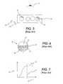
- FIGS. 2-4depict rotatable element 10 and an exemplary system that use such rotatable elements of the prior art.
- rotatable element 10is composed of first layer 20 and second layer 22 and is, by way of example again, a generally spherical body.
- the surface of first layer 20has first coating 91 at a first Zeta potential
- the surface of second layer 22has second coating 93 at a second Zeta potential.
- First coating 91 and second coating 93are chosen such that, when in contact with a dielectric fluid (not shown), first coating 91 has a net positive electric charge with respect to second coating 93 . This is depicted in FIG. 2 by the “+” and “ ⁇ ” symbols respectively.
- first coating 91 and the surface of first layer 20is non-white-colored, indicated in FIG. 2 by hatching, and the combination of second coating 93 and the surface of second layer 22 is white-colored.
- first layer 20 and first coating 91may be the same.
- second layer 22 and second coating 93may be the same.
- FIG. 3depicts no-field set 30 .
- No-field set 30is a subset of randomly oriented rotatable elements in the vicinity of vector field 24 when vector field 24 has zero magnitude.
- Vector field 24is an electric field.
- No-field set 30thus, contains rotatable elements with arbitrary orientations with respect to each other. Therefore, observer 28 in the case of no-field set 30 registers views of the combination of second coating 93 and the surface of second layer 22 , and first coating 91 and the surface of first layer 20 in an unordered sequence.
- Infralayer 26forms the backdrop of the aspect.
- Infralayer 26can consist of any type of material or aspect source, including but not limited to other rotatable elements, or some material that presents a given aspect to observer 28 .
- first aspect set 32will maintain its aspect after applied vector field 24 is removed, in part due to the energy associated with the attraction between rotatable element 10 and the substrate structure, as, for example, cavity walls (not shown). This energy contributes, in part, to the switching characteristics and the memory capability of rotating element sheet material 18 , as disclosed in U.S. Pat. No. 4,126,854, hereinabove incorporated by reference, and discussed in more detail below.
- a rotatable element with multivalued aspectis generally fabricated as disclosed in U.S. Pat. No. 5,919,409, herein incorporated by reference.
- An exemplary rotatable element 10 with multivalued aspectis depicted in FIG. 6 .
- Rotatable element 10 in FIG. 6is composed of first layer 36 , second layer 37 and third layer 38 .
- the surface of third layer 38has third coating 95 at a first Zeta potential
- the surface of first layer 36has first coating 97 at a second Zeta potential such that third coating 95 has a net positive charge, “+,” with respect to first coating 97 when rotatable element 10 is in contact with a dielectric fluid (not shown).
- First layer 36 , first coating 97 , third layer 38 , and third coating 95can be chosen to be transparent to visible light and second layer 22 can be chosen to be opaque or transparent-colored to visible light, such that the rotatable element acts as a “light-valve,” as disclosed, for example, in U.S. Pat. No. 5,767,826, herein incorporated by reference, and in U.S. Pat. No. 5,737,115, herein incorporated by reference.
- the material associated with first layer 36 and first coating 97may be the same.
- the material associated with third layer 38 and third coating 95may be the same.
- Rotatable elements with multivalued aspectare generally utilized in rotating element sheet material that use canted vector fields for addressing.
- a canted vector fieldis a field whose orientation vector in the vicinity of a subset of rotatable elements can be set so as to point in any direction in three-dimensional space.
- U.S. Pat. No. 5,717,545herein incorporated by reference, discloses the use of canted vector fields in order to address rotatable elements.
- the use of canted vector fields with rotating element sheet material 18allows complete freedom in addressing the orientation of a subset of rotatable elements, where the rotatable elements have the addressing polarity discussed above.
- no-field set 30 and first aspect set 32 discussed above in FIGS. 3-5can form the elements of a pixel, where vector field 24 can be manipulated on a pixel by pixel basis using an addressing scheme as discussed, for example, in U.S. Pat. No. 5,717,515, hereinabove incorporated by reference.
- a useful property of rotating element sheet material 18is the ability to maintain a given aspect after the applied vector field 24 for addressing is removed. This ability contributes, in part, to the switching characteristics and the memory capability of rotating element sheet material 18 , as disclosed in U.S. Pat. No. 4,126,854, hereinabove incorporated by reference. This will be referred to as aspect stability.
- the mechanism for aspect stability in the above embodimentsis generally the energy associated with the attraction between the rotatable elements and the substrate structure, or “work function.”
- the applied vector field 24 for addressingmust be strong enough to overcome the work function in order to cause an orientation change; furthermore, the work function must be strong enough to maintain this aspect in the absence of an applied vector field 24 for addressing.
- FIG. 7depicts an exemplary graph of number 54 , N, of rotatable elements that change orientation as a function of applied vector field 24 , V of the prior art.
- Work function 52 , V Wcorresponds to the magnitude of applied vector field 24 when the number 54 of rotatable elements that change orientation in response to vector field 24 has reached saturation level 56 , N S , corresponding to the correlated orientation of all rotatable elements 10 .
- a desired property of rotatable element sheet material 18is a high overall ratio of aspect area to surface area. With respect to chromatic aspects, this can be related to overall reflectance or transmittance. Reflectance of ordinary paper is approximately 85%. Reflectance of currently available electric paper is approximately 15% to 20%.
- a further desired property of rotating element sheet materialis the placement of rotatable elements of different classes to precise positions within the substrate, such that the rotatable elements of given classes are in a regular, repeating pattern in a substantially single layer, and such that the regular, repeating pattern is correlated with an addressing array. In this way, rotatable elements of a given class are located proximal to the corresponding addressing element of the given class.
- each pixel of an aspect viewing areacontains an addressing element for, respectively, cyan, magenta, and yellow, to place all rotatable elements with a cyan-colored aspect proximal to the cyan addressing element, all rotatable elements with a magenta-colored aspect proximal to the magenta addressing element, and all rotatable elements with a yellow-colored aspect proximal to the yellow addressing element.
- a second embodiment of the present invention of rotating element sheet materialcomprises a substrate, a plurality of rotatable elements of a first class, and a plurality of rotatable elements of a second class, where the substrate comprises a cavity-containing matrix having a plurality of cavities of a first class and a plurality of cavities of a second class.
- the plurality of rotatable elements of a first classare disposed within the plurality of cavities of a first class, and the plurality of rotatable elements of a second class are disposed within the plurality of cavities of a second class.
- the plurality of rotatable elements of a first classhave a common first addressing polarity and a common first work function.
- the plurality of rotatable elements of a second classhave a common second addressing polarity and a common second work function. Furthermore, the common first work function is less than the common second work function.
- the plurality of cavities of a first class and the plurality of cavities of a second classare arranged in a substantially single layer and are arranged in a pattern that can be decomposed into a set of first aspect areas, a set of second aspect areas, and a set of null aspect areas.
- a macroscopic region that undergoes a correlated change in orientation of a set of rotatable elements in response to a change in the magnitude of the applied vector fielddetermines an aspect area.
- FIG. 1depicts an exemplary subsection of rotating element sheet material of the prior art.
- FIG. 3depicts an exemplary system of the prior art that uses rotatable elements with two-valued aspects randomly oriented in the presence of an addressing vector field with zero magnitude.
- FIG. 5depicts an alternate view of the exemplary system of FIG. 4 .
- FIG. 6depicts an exemplary rotatable element of the prior art with a multivalued aspect.
- FIG. 8is a perspective view of a exemplary substrate component consistent with the present invention where microrecesses of specified diameters are located in specified regions in a regular, repeating pattern.
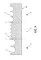
- FIG. 9is a cross section view of a section of the substrate component of FIG. 8 indicating specified regions.
- FIG. 10is a cross section view of the substrate component of FIG. 8 after all of the rotatable elements have been placed in their specified regions, consistent with the present invention.
- FIG. 11is a cross section view of a method of placing the largest sized rotatable elements in the substrate component of FIG. 8 consistent with the present invention.
- FIG. 12is a cross section view of a method of placing the next smallest sized rotatable elements in the substrate component of FIG. 8 after the largest sized rotatable elements are placed, consistent with the present invention.
- FIG. 13is a cross section view of a method of placing the smallest sized rotatable elements in the substrate component of FIG. 8 after the two larger-sized rotatable elements are placed, consistent with the present invention.
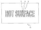
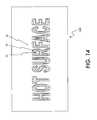
- FIG. 14is a perspective view of an exemplary substrate component consistent with the present invention and displaying two aspect areas and null areas associated with a dynamic message “HOT SURFACE.”
- FIG. 16is a cross section view of the substrate component of FIG. 15 after all of the rotatable elements have been placed in their appropriate microrecesses within the first aspect area, consistent with the present invention.
- FIG. 17is a perspective view of a section of the second aspect area of the substrate component of FIG. 14 .
- FIG. 18depicts an exemplary graph of the number of rotatable elements that change orientation as a function of applied field, displaying work function and saturation numbers for the microrecesses and rotatable elements of FIG. 16 .
- FIG. 20is a perspective view of rotating element sheet material assembled with the substrate component of FIG. 14 and with an applied vector field at the highest work function of FIG. 18 .
- One embodiment of the present inventioncomprises rotating element sheet material with a microstructured substrate component, and a method of assembling such rotating element sheet material.
- a method of useimplements a macroscopic addressing technique for rotating element sheet material.
- aspectsrefers to a common response to incident electromagnetic energy of interest. For example, if the incident electromagnetic energy of interest lies in the visible spectrum, then a first aspect can correspond to a black appearance, and a second aspect can correspond to a white appearance. If the incident electromagnetic energy of interest lies in the x-ray region, then a first aspect can correspond to the transmission of the x-ray energy, while a second aspect can correspond to the absorption of the x-ray energy.
- the “common response”can comprise any of the phenomena of absorption, reflection, polarization, transmission, fluorescence, or any combination thereof.
- observerrefers to a human perceiver, or to a human perceiver in conjunction with an apparatus sensitive to the electromagnetic energy of interest. If the electromagnetic energy of interest lies in the visible spectrum, then observer can refer to a human perceiver. If the electromagnetic energy of interest lies outside of the visible spectrum, then observer refers to an apparatus sensitive to the electromagnetic energy and capable of resolving the aspects of interest into human perceivable form.
- vector fieldrefers to a field whose amplitude in space is capable of having a magnitude and a direction.
- Vector fields of interest in the present inventioninclude electric fields, magnetic fields, or electromagnetic fields.
- work functionrefers to the amount of energy necessary to overcome the attraction between a rotatable element and the substrate structure so as to enable a change of orientation, as for example, between the rotatable element and the cavity walls.
- a host of factorsinfluence the magnitude of the energy associated with the work function including, but not limited to: surface tension of enabling fluid in contact with rotatable elements; the relative specific gravity of enabling fluid and rotatable element; magnitude of charge on rotatable element; relative electronic permittivity of enabling fluid and substrate structure; “stickiness” of substrate structure; and other residual vector fields that may be present.
- macroscopicrefers to an aspect or region that is large enough to be perceived by an unaided observer, as, for example, aspects that convey warnings or other information to human perceivers.
- first addressing region 82corresponds to addressing a yellow-colored aspect, indicated by the symbol “Y”
- second addressing region 84corresponds to addressing a cyan-colored aspect indicated by the symbol “C”
- third addressing region 86corresponds to addressing a magenta-colored aspect indicated by the symbol “M.”
- Pixel space 90 containing microrecesses of a first class 72 , microrecesses of a second class 74 , and microrecesses of a third class 76is repeated to form a regular, repeating pattern in a preferred embodiment of the present invention, where the above microrecesses are correlated with an addressing array with the pattern given by first addressing region 82 , second addressing region 84 and third addressing region 86 .
- microrecesses of a first class 72are smaller than microrecesses of a second class 74 , which are smaller than microrecesses of a third class 76 .
- microrecesses of a first class 72are designed to accommodate rotatable elements of a first class 126
- microrecesses of a second class 74are designed to accommodate rotatable elements of a second class 128
- microrecesses of a third class 76are designed to accommodate rotatable elements of a third class 130 .
- FIG. 10shows a cross section of substrate component 120 consistent with the present invention. Also shown in FIG. 10 are vertical lines indicating the boundaries between first addressing region 82 , second addressing region 84 , and third addressing region 86 .
- rotatable elements of a first class 126 , rotatable elements of a second class 128 , and rotatable elements of a third class 130have one aspect in common and a second aspect that is different for each. This is indicated in FIG. 10 .
- rotatable elements of a first class 126 , rotatable elements of a second class 128 , and rotatable elements of a third class 130are all bichromal rotatable elements with a first orientation that presents a white-colored aspect.
- a second orientation for each of the rotatable elementspresents, in turn, a yellow-colored aspect for rotatable elements of a first class 126 , a cyan-colored aspect for rotatable elements of a second class 128 , and a magenta-colored aspect for rotatable elements of a third class 130 .
- a yellow-colored aspect for rotatable elements of a first class 126presents, in turn, a yellow-colored aspect for rotatable elements of a first class 126
- a cyan-colored aspect for rotatable elements of a second class 128presents, in turn, a magenta-colored aspect for rotatable elements of a third class 130 .
- the addressing regions depicted in FIG. 8are correlated with the addressing of a particular aspect.
- first addressing region 82is correlated with addressing a yellow-colored aspect
- second addressing region 84is correlated with addressing a cyan-colored aspect
- third addressing region 86is correlated with addressing a magenta-colored aspect.
- Such an addressing systemmay be used, for example, as disclosed in U.S. Pat. No. 5,767,826, hereinabove incorporated by reference.
- microrecessesare depicted, other shapes such as cylindrical shapes, are also possible.
- each microrecessis indicated as accommodating one rotatable element, one of skill in the art will appreciate that a given microrecess can accommodate more than one rotatable element, as in the case where the microrecesses are grooves.
- FIG. 8depicts microrecesses of a first class 72 , microrecesses of a second class 74 , and microrecesses of a third class 76 in a non-optimally packed configuration
- such microrecessesmay be ordered such that a higher density of any of rotatable elements of a first class 126 , rotatable elements of a second class 128 , and rotatable elements of a third class 130 may be achieved.
- rotating element sheet materialis finished by the application of an enabling fluid and a cover sheet to complete the substrate, as disclosed, for example, in U.S. Pat. No. 5,815,306, herein incorporated by reference.
- the combination of the cover sheet and the microstructured substrate component 120 described abovewill define a plurality of cavities of a first class, a plurality of cavities of a second class, and a plurality of cavities of a third class, where the plurality of cavities of all classes will be disposed substantially in a single layer.
- the plurality of cavities of a first class, a plurality of cavities of a second class, and a plurality of cavities of a third classwill form a regular, repeating pattern, based on the regular, repeating pattern of microrecesses of a first class 72 , microrecesses of a second class 74 , and microrecesses of a third class 76 , as depicted, for example, in FIG. 8 .
- Such rotating element sheet materialmay then be easily coupled with an addressing system, where the addressing system, at the pixel level, is correlated with first addressing region 82 , second addressing region 84 , and third addressing region 86 , to address, respectively, a yellow-colored aspect, a cyan-colored aspect, and a magenta-colored aspect.
- the addressing systemat the pixel level, is correlated with first addressing region 82 , second addressing region 84 , and third addressing region 86 , to address, respectively, a yellow-colored aspect, a cyan-colored aspect, and a magenta-colored aspect.
- doctor blade 124can be used to remove excess rotatable elements of a third class 130 .
- Other means, such as agitation of substrate component 120are also available to remove excess rotatable elements of a third class 130 .
- rotatable elements of a second class 128can be dispersed over substrate component 120 , again, to settle into appropriately-sized microrecesses. Again, rotatable elements of a second class 128 will not settle into the microrecesses too small for them, and cannot settle into the larger microrecesses since they are already populated. Furthermore, doctor blade 124 can be used to remove excess rotatable elements of a second class 128 , while riding over the tops of those rotatable elements of a second class 128 that have positioned into microrecesses. This is depicted in FIG. 12 .
- rotatable elements of a first class 126are dispersed over substrate component 120 , again, to settle into appropriate microrecesses. Again, rotatable elements of a first class 126 cannot settle into the larger recesses since they are already populated. Furthermore, doctor blade 124 can be used to remove excess rotatable elements of a first class 126 , while riding over the tops of those rotatable elements of a first class 126 that have positioned into microrecesses. This is depicted in FIG. 13 . Rotating element sheet material is then finished by application of an enabling fluid and a cover sheet to complete the substrate, as disclosed, for example, in U.S. Pat. No. 5,815,306, herein incorporated by reference.
- the combination of the cover sheet and the microstructured substrate component 120 described abovewill define a plurality of cavities of a first class, a plurality of cavities of a second class, and a plurality of cavities of a third class, where the plurality of cavities of all classes will be disposed substantially in a single layer. Furthermore, the plurality of cavities of a first class, a plurality of cavities of a second class, and a plurality of cavities of a third class will form a regular, repeating pattern, based on the regular, repeating pattern of microrecesses of a first class 72 , microrecesses of a second class 74 , and microrecesses of a third class 76 , as depicted, for example, in FIG. 8 .
- the fabrication of different-sized microrecesses in the substrate componentcan be accomplished by a number of means. For example, precise molding can be used, as well as conventional hot stamping with a metal master or embossing.
- Conventional photo-lithographic patterningcan be accomplished using optical masking and selective etching, controlled laser ablation, or using a photosensitive material, as, for example, a photo-resist, as described in U.S. Pat. No. 5,815,306, hereinabove incorporated by reference.
- FIG. 14A perspective view of a substrate component 140 consistent with a second embodiment of the present invention is depicted in FIG. 14 .
- the aspect areasare macroscopic regions correlated with a given work function threshold, and given rotatable elements displaying a given macroscopic aspect.
- FIG. 14there is a fixed message “HOT SURFACE.”
- a close-up view of the microstructured surface associated with first aspect area 62is depicted in FIG. 15 .
- FIG. 15A close-up view of the microstructured surface associated with first aspect area 62 is depicted in FIG. 15 .
- first aspect area 62contains two types of microrecesses: microrecesses of a first class 110 and microrecesses of a second class 108 .
- microrecesses of a first class 110 and microrecesses of a second class 108have different characteristic diameters. Rather than having each set of microrecesses correlated with a given addressing region, however, both microrecesses of a first class 110 and microrecesses of a second class 108 are contained within one macroscopic addressing region. As shown in FIG.
- microrecesses of a first class 110are designed to accommodate rotatable elements of a first class 111 , which presents a white-colored aspect in a first orientation, and a yellow-colored aspect in a second orientation.
- microrecesses of a second class 108are designed to accommodate rotatable elements of a second class 109 , which presents a white-colored aspect in a first orientation, and an orange-colored aspect in a second orientation.
- the use of rotatable elements with a yellow-colored aspect and rotatable elements with an orange-colored aspectis exemplary only and other choices are also consistent with the present invention.
- FIG. 17A close-up view of the microstructured surface associated with second aspect area 64 of FIG. 14 is depicted in FIG. 17 .
- second aspect area 64contains microrecesses of a second class 108 only.
- microrecesses of a second class 108are designed to accommodate a rotatable elements of a second class 109 , which presents a white-colored aspect in a first orientation, and an orange-colored aspect in a second orientation.
- FIG. 18The work function associated with microrecesses of a first class 110 and microrecesses of a second class 108 containing rotatable elements of a first class 111 and rotatable elements of a second class 109 respectively is depicted in FIG. 18 .
- the larger the diameter of a rotatable elementthe larger the associated work function, other things being equal.
- the lower threshold 102represents the threshold necessary to address the saturation number 112 , N S Y , of the rotatable elements of a first class 111 ;
- the higher threshold 104represents the threshold necessary to address both the saturation number 112 , N S Y , of rotatable elements of a first class 111 and the saturation number 114 , N S O , of rotatable elements of a second class 109 .
- the fabrication of different-sized microrecesses in the substrate componentcan be accomplished by a number of means. For example, precise molding can be used, as well as conventional hot stamping with a metal master or embossing.
- Conventional photo-lithographic patterningcan be accomplished using optical masking and selective etching, controlled laser ablation, or using a photosensitive material, as, for example, a photo-resist, as described in U.S. Pat. No. 5,815,306, hereinabove incorporated by reference.
- the plurality of cavities of a first class, a plurality of cavities of a second class, and a plurality of cavities of a third classwill form a macroscopic pattern, based on the macroscopic pattern of microrecesses of a first class 108 and microrecesses of a second class 110 , as depicted, for example, in FIGS. 14, 15 , and 17 .
- rotating element sheet material 18is constructed using substrate component 140 of FIG. 14 by applying enabling fluid and a cover sheet, as disclosed in U.S. Pat. No. 5,815,306, hereinabove incorporated by reference.
- the combination of the cover sheet and the microstructured substrate component 140 described abovewill define a plurality of cavities of a first class and a plurality of cavities of a second class where the plurality of cavities will be disposed substantially in a single layer.
- FIGS. 19 and 20indicate how the fixed message “HOT SURFACE” acquires a dynamic attribute according to the magnitude of the addressing vector field.
- the fixed message of FIG. 20can be made to appear.
- itis the same message “HOT SURFACE” but in a bolder typeface in the above embodiment, as well as presenting an orange-colored aspect to a favorably situated observer.
Landscapes
- Physics & Mathematics (AREA)
- Engineering & Computer Science (AREA)
- General Physics & Mathematics (AREA)
- Theoretical Computer Science (AREA)
- Computer Hardware Design (AREA)
- Health & Medical Sciences (AREA)
- Life Sciences & Earth Sciences (AREA)
- Molecular Biology (AREA)
- Optics & Photonics (AREA)
- Electrochromic Elements, Electrophoresis, Or Variable Reflection Or Absorption Elements (AREA)
Abstract
Description
Claims (12)
Priority Applications (1)
| Application Number | Priority Date | Filing Date | Title |
|---|---|---|---|
| US09/563,504US6504525B1 (en) | 2000-05-03 | 2000-05-03 | Rotating element sheet material with microstructured substrate and method of use |
Applications Claiming Priority (1)
| Application Number | Priority Date | Filing Date | Title |
|---|---|---|---|
| US09/563,504US6504525B1 (en) | 2000-05-03 | 2000-05-03 | Rotating element sheet material with microstructured substrate and method of use |
Publications (1)
| Publication Number | Publication Date |
|---|---|
| US6504525B1true US6504525B1 (en) | 2003-01-07 |
Family
ID=24250767
Family Applications (1)
| Application Number | Title | Priority Date | Filing Date |
|---|---|---|---|
| US09/563,504Expired - LifetimeUS6504525B1 (en) | 2000-05-03 | 2000-05-03 | Rotating element sheet material with microstructured substrate and method of use |
Country Status (1)
| Country | Link |
|---|---|
| US (1) | US6504525B1 (en) |
Cited By (13)
| Publication number | Priority date | Publication date | Assignee | Title |
|---|---|---|---|---|
| US20020167481A1 (en)* | 2001-05-11 | 2002-11-14 | Wong Yoon Kean | Page flicking mechanism for electronic display devices that paginate content |
| US20020185216A1 (en)* | 1999-12-17 | 2002-12-12 | Xerox Corporation | System and method for rotatable element assembly and laminate substrate assembly |
| US20030202235A1 (en)* | 2002-04-30 | 2003-10-30 | Mario Rabinowitz | Dynamic multi-wavelength switching ensemble |
| US20040189766A1 (en)* | 2000-08-17 | 2004-09-30 | Xerox Corporation | Electromagnetophoretic display system and method |
| US20080206690A1 (en)* | 2007-02-26 | 2008-08-28 | Joseph Kennedy | Compositions, coatings and films for tri-layer patterning applications and methods of preparation thereof |
| US7523546B2 (en) | 2005-05-04 | 2009-04-28 | Nokia Corporation | Method for manufacturing a composite layer for an electronic device |
| US20110069001A1 (en)* | 2009-09-18 | 2011-03-24 | Samsung Electro-Mechanics Co., Ltd. | Electronic paper display device and method of manufacturing the same |
| US20120274619A1 (en)* | 2011-04-28 | 2012-11-01 | Samsung Electro-Mechanics Co., Ltd. | Electronic paper display device and driving method thereof |
| US8557877B2 (en) | 2009-06-10 | 2013-10-15 | Honeywell International Inc. | Anti-reflective coatings for optically transparent substrates |
| US8864898B2 (en) | 2011-05-31 | 2014-10-21 | Honeywell International Inc. | Coating formulations for optical elements |
| US20150322637A1 (en)* | 2013-06-19 | 2015-11-12 | M.B.G. Industries | Sinuous traffic line |
| US20180299688A1 (en)* | 2015-10-08 | 2018-10-18 | Dai Nippon Printing Co., Ltd. | Particles, optical sheet, screen, display device, particle inspection device, particle manufacturing device, particle inspection method, particle manufacturing method, screen inspection method, and screen manufacturing method |
| US10544329B2 (en) | 2015-04-13 | 2020-01-28 | Honeywell International Inc. | Polysiloxane formulations and coatings for optoelectronic applications |
Citations (203)
| Publication number | Priority date | Publication date | Assignee | Title |
|---|---|---|---|---|
| US2326634A (en) | 1941-12-26 | 1943-08-10 | Minnesota Mining & Mfg | Reflex light reflector |
| US2354048A (en) | 1940-08-03 | 1944-07-18 | Minnesota Mining & Mfg | Flexible lenticular optical sheet |
| US2354049A (en) | 1944-01-19 | 1944-07-18 | Minnesota Mining & Mfg | Backless reflex light reflector |
| US2354018A (en) | 1940-08-03 | 1944-07-18 | Minnesota Mining & Mfg | Light reflector sheet |
| US2407680A (en) | 1945-03-02 | 1946-09-17 | Minnesota Mining & Mfg | Reflex light reflector |
| US2600963A (en) | 1948-04-08 | 1952-06-17 | Charles C Bland | Method and apparatus for forming glass beads |
| US2684788A (en) | 1950-02-09 | 1954-07-27 | Flex O Lite Mfg Corp | Bead dispenser |
| US2794301A (en) | 1953-01-29 | 1957-06-04 | Flex O Lite Mfg Corp | Production of free-flowing glass beads |
| US2950985A (en) | 1957-04-11 | 1960-08-30 | Flex O Lite Mfg Corp | Starch treated free flowing glass beads |
| US2965921A (en) | 1957-08-23 | 1960-12-27 | Flex O Lite Mfg Corp | Method and apparatus for producing glass beads from a free falling molten glass stream |
| US2980547A (en) | 1957-05-03 | 1961-04-18 | Flex O Lite Mfg Corp | High refractive index glass beads |
| US3036388A (en) | 1961-10-27 | 1962-05-29 | Clarence R Tate | Magnetic writing materials set |
| US3063388A (en) | 1960-05-12 | 1962-11-13 | Preco Inc | Load dividers for goods containing compartments, such as those of carriers |
| US3150947A (en) | 1961-07-13 | 1964-09-29 | Flex O Lite Mfg Corp | Method for production of glass beads by dispersion of molten glass |
| US3222204A (en) | 1960-04-20 | 1965-12-07 | Minnesota Mining & Mfg | Process of making beaded coatings and films from glass beads treated with oleophobic sizing agent |
| US3243273A (en) | 1957-08-12 | 1966-03-29 | Flex O Lite Mfg Corp | Method and apparatus for production of glass beads by dispersion of molten glass |
| US3310391A (en) | 1962-08-31 | 1967-03-21 | Flex O Lite Mfg Corp | Method of and apparatus for production of glass beads by use of a rotating wheel |
| US3406363A (en) | 1966-05-26 | 1968-10-15 | Clarence R. Tate | Multicolored micromagnets |
| US3594065A (en) | 1969-05-26 | 1971-07-20 | Alvin M Marks | Multiple iris raster |
| US3615993A (en) | 1967-07-14 | 1971-10-26 | Ibm | Magnetic ball production method |
| US3617333A (en) | 1968-10-30 | 1971-11-02 | Gen Steel Ind Inc | Process for flotation treatment of glass beads |
| US3648281A (en) | 1969-12-30 | 1972-03-07 | Ibm | Electrostatic display panel |
| US3795435A (en) | 1969-05-09 | 1974-03-05 | Swarovski & Co | Reflex light reflection sheet and method for its manufacture |
| US3915771A (en) | 1974-03-04 | 1975-10-28 | Minnesota Mining & Mfg | Pavement-marking tape |
| US3982334A (en) | 1970-03-27 | 1976-09-28 | Thalatta, Inc. | Compartmentalized micromagnet display device |
| US4001140A (en) | 1974-07-10 | 1977-01-04 | Ncr Corporation | Capsule manufacture |
| US4002022A (en) | 1974-10-01 | 1977-01-11 | Lopez C Guillermo | Electro-mechanical sign structure with alternating faces formed by several adjacent dihedral angles |
| US4082426A (en) | 1976-11-26 | 1978-04-04 | Minnesota Mining And Manufacturing Company | Retroreflective sheeting with retroreflective markings |
| USRE29742E (en) | 1973-11-05 | 1978-08-29 | Minnesota Mining And Manufacturing Company | Retroreflective protective helmet |
| US4117194A (en) | 1972-05-04 | 1978-09-26 | Rhone-Poulenc-Textile | Bicomponent filaments with a special cross-section |
| US4117192A (en) | 1976-02-17 | 1978-09-26 | Minnesota Mining And Manufacturing Company | Deformable retroreflective pavement-marking sheet material |
| US4126854A (en) | 1976-05-05 | 1978-11-21 | Xerox Corporation | Twisting ball panel display |
| US4143103A (en) | 1976-05-04 | 1979-03-06 | Xerox Corporation | Method of making a twisting ball panel display |
| US4143472A (en) | 1977-04-11 | 1979-03-13 | Pilot Man-Nen Hitsu Kabushiki Kaisha | Displaying magnetic panel and its display device |
| US4229732A (en) | 1978-12-11 | 1980-10-21 | International Business Machines Corporation | Micromechanical display logic and array |
| US4232084A (en) | 1978-01-25 | 1980-11-04 | Thalatta, Inc. | Sheets containing microencapsulated color-coded micromagnets |
| US4253909A (en) | 1976-04-12 | 1981-03-03 | Magnavox Government And Industrial Electronics Co. | Surface treating a portion of small articles |
| US4256677A (en) | 1976-04-12 | 1981-03-17 | Magnavox Government And Industrial Electronics Co. | Apparatus and method for making small spheres |
| US4261653A (en) | 1978-05-26 | 1981-04-14 | The Bendix Corporation | Light valve including dipolar particle construction and method of manufacture |
| US4268413A (en) | 1977-08-25 | 1981-05-19 | Wolfgang Dabisch | Bodies with reversibly variable temperature-dependent light absorbence |
| US4267946A (en) | 1979-10-01 | 1981-05-19 | Thatcher Gary G | Particulate matter dispensing device |
| US4273672A (en) | 1971-08-23 | 1981-06-16 | Champion International Corporation | Microencapsulation process |
| US4283438A (en) | 1979-12-26 | 1981-08-11 | Magnavox Government And Industrial Electronics Company | Method for individually encapsulating magnetic particles |
| US4288788A (en) | 1980-05-19 | 1981-09-08 | General Motors Corporation | Electrostatic alpha-numeric display |
| US4299880A (en) | 1979-11-15 | 1981-11-10 | Minnesota Mining And Manufacturing Company | Demand and timed renewing imaging media |
| US4367920A (en) | 1979-10-01 | 1983-01-11 | Minnesota Mining And Manufacturing Company | Retroflective sheeting |
| US4368952A (en) | 1979-12-11 | 1983-01-18 | Pilot Man-Nen-Hitsu Kabushiki Kaisha | Magnetic display panel using reversal magnetism |
| US4374889A (en) | 1981-12-07 | 1983-02-22 | Minnesota Mining And Manufacturing Company | Oil-repellent microvoid-imaging material |
| US4381616A (en) | 1981-09-11 | 1983-05-03 | Saxer Norman K | Internally illuminated rotatable pictorial menu display |
| US4402062A (en) | 1981-05-14 | 1983-08-30 | Batchelder J Samuel | Method and apparatus for dielectrophoretic storage and retrieval of information |
| US4411973A (en) | 1980-10-14 | 1983-10-25 | Eastman Kodak Company | Elements containing ordered wall arrays and processes for their fabrication |
| US4418098A (en) | 1980-09-02 | 1983-11-29 | Minnesota Mining & Manufacturing Company | Imaging media capable of displaying sharp indicia |
| US4418346A (en) | 1981-05-20 | 1983-11-29 | Batchelder J Samuel | Method and apparatus for providing a dielectrophoretic display of visual information |
| US4419383A (en) | 1979-12-26 | 1983-12-06 | Magnavox Government And Industrial Electronics Company | Method for individually encapsulating magnetic particles |
| US4438160A (en) | 1982-01-18 | 1984-03-20 | Sony Corporation | Method of making a rotary ball display device |
| US4441791A (en) | 1980-09-02 | 1984-04-10 | Texas Instruments Incorporated | Deformable mirror light modulator |
| US4457723A (en) | 1981-06-11 | 1984-07-03 | Thalatta, Inc. | Color changeable fabric |
| US4492435A (en) | 1982-07-02 | 1985-01-08 | Xerox Corporation | Multiple array full width electro mechanical modulator |
| US4500172A (en) | 1981-12-28 | 1985-02-19 | Hughes Aircraft Company | Two color liquid crystal light valve image projection system with single prepolarizer |
| US4511210A (en)* | 1979-10-01 | 1985-04-16 | Minnesota Mining And Manufacturing Company | Retroreflective sheeting |
| US4532608A (en) | 1982-06-25 | 1985-07-30 | Wu Jiun Tsong | Memory device |
| US4569857A (en) | 1979-10-01 | 1986-02-11 | Minnesota Mining And Manufacturing Company | Retroreflective sheeting |
| US4592628A (en) | 1981-07-01 | 1986-06-03 | International Business Machines | Mirror array light valve |
| US4627689A (en) | 1983-12-08 | 1986-12-09 | University Of Pittsburgh | Crystalline colloidal narrow band radiation filter |
| US4632517A (en) | 1983-12-08 | 1986-12-30 | University Of Pittsburgh | Crystalline colloidal narrow band radiation filter |
| US4675476A (en) | 1984-10-11 | 1987-06-23 | Nec Corporation | Magnetophoresis type display and graphic input/output device using the same |
| US4678695A (en) | 1985-12-23 | 1987-07-07 | Minnesota Mining And Manufacturing Company | Encapsulated flattop retroreflective sheeting and method for producing the same |
| US4688900A (en) | 1984-03-19 | 1987-08-25 | Kent State University | Light modulating material comprising a liquid crystal dispersion in a plastic matrix |
| US4695528A (en) | 1980-07-16 | 1987-09-22 | Wolfgang Dabisch | Process for forming images using body with reversible fixable and temperature-variable light extinctions |
| US4710732A (en) | 1984-07-31 | 1987-12-01 | Texas Instruments Incorporated | Spatial light modulator and method |
| US4713295A (en) | 1985-03-28 | 1987-12-15 | Glaverbel | Method of modifying the wettability of glass beads, glass beads polymeric material incorporating such glass beads, and method of applying reflective markings to a surface |
| US4721649A (en) | 1985-05-08 | 1988-01-26 | Minnesota Mining And Manufacturing Company | Retroreflective sheeting |
| US4725494A (en) | 1982-09-02 | 1988-02-16 | Minnesota Mining And Manufacturing Co. | Retroreflective sheeting |
| US4729687A (en) | 1985-02-20 | 1988-03-08 | Minnesota Mining And Manufacturing Company | Imaging device |
| US4740266A (en) | 1985-07-01 | 1988-04-26 | Wu Jiun Tsong | Method of making memory devices |
| US4781789A (en) | 1985-07-01 | 1988-11-01 | Wu Jiun Tsong | Method of making memory devices |
| US4781790A (en) | 1985-07-01 | 1988-11-01 | Wu Jiun Tsong | Method of making memory devices |
| US4783236A (en) | 1985-07-01 | 1988-11-08 | Wu Jiun Tsong | Method of making memory devices |
| US4795528A (en) | 1985-07-01 | 1989-01-03 | Wu Jiun Tsong | Method of making memory devices |
| US4795243A (en) | 1983-06-10 | 1989-01-03 | Canon Kabushiki Kaisha | Granular member moving method and apparatus |
| US4810431A (en) | 1986-05-23 | 1989-03-07 | Ontario Research Foundation | Method of manufacturing plastic particles for a particle display |
| US4837071A (en) | 1986-11-25 | 1989-06-06 | Ricoh Company, Ltd. | Information display medium |
| US4877253A (en) | 1987-02-06 | 1989-10-31 | Minnesota Mining And Manufacturing Company | Reusable bingo card |
| US4890902A (en) | 1985-09-17 | 1990-01-02 | Kent State University | Liquid crystal light modulating materials with selectable viewing angles |
| US4919521A (en) | 1987-06-03 | 1990-04-24 | Nippon Sheet Glass Co., Ltd. | Electromagnetic device |
| US4931019A (en) | 1988-09-01 | 1990-06-05 | Pennwalt Corporation | Electrostatic image display apparatus |
| US4948232A (en) | 1983-12-16 | 1990-08-14 | Alf Lange | Device for the presentation of information with rollable plastic substrate |
| US4956619A (en) | 1988-02-19 | 1990-09-11 | Texas Instruments Incorporated | Spatial light modulator |
| US4991941A (en) | 1988-06-13 | 1991-02-12 | Kaiser Aerospace & Electronics Corporation | Method and apparatus for multi-color display |
| US4994204A (en) | 1988-11-04 | 1991-02-19 | Kent State University | Light modulating materials comprising a liquid crystal phase dispersed in a birefringent polymeric phase |
| US5039557A (en) | 1989-10-26 | 1991-08-13 | White Terrence H | Method for embedding reflective beads in thermoplastic pavement marking lines |
| US5066559A (en) | 1990-01-22 | 1991-11-19 | Minnesota Mining And Manufacturing Company | Liquid electrophotographic toner |
| US5075186A (en) | 1989-12-13 | 1991-12-24 | Xerox Corporation | Image-wise adhesion layers for printing |
| US5128203A (en) | 1988-02-19 | 1992-07-07 | Glaverbel | Marking comprising glass beads in a matrix |
| US5131736A (en) | 1990-05-30 | 1992-07-21 | The United States Of America As Represented By The Department Of Energy | Solid colloidal optical wavelength filter |
| US5151032A (en) | 1990-07-13 | 1992-09-29 | Kabushiki Kaisha Pilot | Magnetophoretic display panel |
| US5155607A (en) | 1990-03-16 | 1992-10-13 | Fuji Xerox Co., Ltd. | Optical modulation display device and display method using the same |
| US5157011A (en) | 1989-11-17 | 1992-10-20 | Oki Electric Industry Co., Ltd. | Thermoreversible recording medium, apparatus utilizing the same and method for fabricating the same |
| US5189658A (en) | 1989-06-30 | 1993-02-23 | Moses Klaus M | Device for recording information on an optical data carrier |
| US5219820A (en) | 1990-11-22 | 1993-06-15 | Ricoh Company, Ltd. | Reversible thermosensitive recording material and method of producing the same |
| US5223473A (en) | 1990-11-21 | 1993-06-29 | Xerox Corporation | Self-cleaning carbonless paper |
| US5226099A (en) | 1991-04-26 | 1993-07-06 | Texas Instruments Incorporated | Digital micromirror shutter device |
| US5233459A (en) | 1991-03-06 | 1993-08-03 | Massachusetts Institute Of Technology | Electric display device |
| US5249000A (en) | 1989-11-17 | 1993-09-28 | Oki Electric Industry Co., Ltd. | Thermoreversible recording medium, apparatus utilizing the same and method for fabricating the same |
| US5251048A (en) | 1992-05-18 | 1993-10-05 | Kent State University | Method and apparatus for electronic switching of a reflective color display |
| US5262374A (en) | 1989-11-17 | 1993-11-16 | Oki Electric Industry Co., Ltd. | Thermoreversible recording medium, apparatus utilizing the same and method for fabricating the same |
| US5262098A (en) | 1992-12-23 | 1993-11-16 | Xerox Corporation | Method and apparatus for fabricating bichromal balls for a twisting ball display |
| US5270872A (en) | 1989-07-20 | 1993-12-14 | The United States Of America As Represented By The Secretary Of The Air Force | Superconducting submicron filter |
| US5274460A (en) | 1990-07-04 | 1993-12-28 | Mitsubishi Denki Kabushiki Kaisha | Method of and apparatus for rewritable recording and erasing and rewritable recording film |
| US5290066A (en) | 1990-12-06 | 1994-03-01 | Mody Hemant K | Magnetic label and use thereof |
| US5315418A (en) | 1992-06-17 | 1994-05-24 | Xerox Corporation | Two path liquid crystal light valve color display with light coupling lens array disposed along the red-green light path |
| US5315776A (en) | 1992-10-07 | 1994-05-31 | Everbrite, Inc. | Multiple-display sign device |
| US5331454A (en) | 1990-11-13 | 1994-07-19 | Texas Instruments Incorporated | Low reset voltage process for DMD |
| US5344594A (en) | 1991-10-29 | 1994-09-06 | Xerox Corporation | Method for the fabrication of multicolored balls for a twisting ball display |
| US5351995A (en) | 1992-01-29 | 1994-10-04 | Apple Computer, Inc. | Double-sided, reversible electronic paper |
| US5354598A (en) | 1992-04-10 | 1994-10-11 | Minnesota Mining And Manufacturing Company | Article capable of displaying defined images |
| US5363222A (en) | 1989-06-07 | 1994-11-08 | Hughes Aircraft Company | Compact optical system for a single light valve full-color projector |
| US5383008A (en) | 1993-12-29 | 1995-01-17 | Xerox Corporation | Liquid ink electrostatic image development system |
| US5384067A (en) | 1991-05-02 | 1995-01-24 | Kent State University | Grey scale liquid crystal material |
| US5389945A (en) | 1989-11-08 | 1995-02-14 | Xerox Corporation | Writing system including paper-like digitally addressed media and addressing device therefor |
| US5389426A (en) | 1993-01-25 | 1995-02-14 | Minnesota Mining And Manufacturing Company | Article for use in forming a permanent image using a temporary marker |
| US5397503A (en) | 1991-04-18 | 1995-03-14 | Idemitsu Kosan Co., Ltd. | Liquid crystal composition and information display apparatus using the liquid crystal composition |
| US5411398A (en) | 1992-05-29 | 1995-05-02 | Japan Capsular Products, Inc. | Magnetic display system |
| US5416996A (en) | 1993-03-16 | 1995-05-23 | Clemens; Richard | Display apparatus |
| US5432526A (en) | 1970-12-28 | 1995-07-11 | Hyatt; Gilbert P. | Liquid crystal display having conductive cooling |
| US5432534A (en) | 1990-12-26 | 1995-07-11 | Ricoh Company, Ltd. | Reversible thermosensitive coloring composition, recording medium, recording method, and image display apparatus using the recording medium |
| US5459602A (en) | 1993-10-29 | 1995-10-17 | Texas Instruments | Micro-mechanical optical shutter |
| US5469020A (en) | 1994-03-14 | 1995-11-21 | Massachusetts Institute Of Technology | Flexible large screen display having multiple light emitting elements sandwiched between crossed electrodes |
| US5515075A (en) | 1991-06-28 | 1996-05-07 | Citizen Watch Co., Ltd | Multicolor display apparatus |
| US5535047A (en) | 1995-04-18 | 1996-07-09 | Texas Instruments Incorporated | Active yoke hidden hinge digital micromirror device |
| US5582700A (en) | 1995-10-16 | 1996-12-10 | Zikon Corporation | Electrophoretic display utilizing phase separation of liquids |
| US5604027A (en) | 1995-01-03 | 1997-02-18 | Xerox Corporation | Some uses of microencapsulation for electric paper |
| US5627562A (en) | 1993-11-26 | 1997-05-06 | Skodlar; Rafael | Magnetic display apparatus |
| US5659330A (en) | 1996-05-31 | 1997-08-19 | Xerox Corporation | Electrocapillary color display sheet |
| US5667924A (en) | 1996-02-14 | 1997-09-16 | Xerox Corporation | Superparamagnetic image character recognition compositions and processes of making and using |
| US5703671A (en) | 1995-08-28 | 1997-12-30 | Fuji Photo Film Co., Ltd. | Shading correction method, photographic printer and index print production apparatus |
| US5708525A (en) | 1995-12-15 | 1998-01-13 | Xerox Corporation | Applications of a transmissive twisting ball display |
| US5717283A (en) | 1996-01-03 | 1998-02-10 | Xerox Corporation | Display sheet with a plurality of hourglass shaped capsules containing marking means responsive to external fields |
| US5717515A (en) | 1995-12-15 | 1998-02-10 | Xerox Corporation | Canted electric fields for addressing a twisting ball display |
| US5717514A (en) | 1995-12-15 | 1998-02-10 | Xerox Corporation | Polychromal segmented balls for a twisting ball display |
| US5724064A (en) | 1995-12-27 | 1998-03-03 | Xerox Corporation | Computing system with an interactive display |
| US5723204A (en) | 1995-12-26 | 1998-03-03 | Xerox Corporation | Two-sided electrical paper |
| US5731792A (en) | 1996-05-06 | 1998-03-24 | Xerox Corporation | Electrocapillary color display sheet |
| US5737115A (en)* | 1995-12-15 | 1998-04-07 | Xerox Corporation | Additive color tristate light valve twisting ball display |
| US5739946A (en) | 1995-09-21 | 1998-04-14 | Kabushiki Kaisha Toshiba | Display device |
| US5739801A (en) | 1995-12-15 | 1998-04-14 | Xerox Corporation | Multithreshold addressing of a twisting ball display |
| US5751268A (en) | 1995-12-15 | 1998-05-12 | Xerox Corporation | Pseudo-four color twisting ball display |
| US5754332A (en) | 1996-06-27 | 1998-05-19 | Xerox Corporation | Monolayer gyricon display |
| US5757345A (en) | 1996-05-06 | 1998-05-26 | Xerox Corportion | Electrocapillary color display sheet |
| US5760761A (en) | 1995-12-15 | 1998-06-02 | Xerox Corporation | Highlight color twisting ball display |
| US5767826A (en) | 1995-12-15 | 1998-06-16 | Xerox Corporation | Subtractive color twisting ball display |
| US5777782A (en) | 1996-12-24 | 1998-07-07 | Xerox Corporation | Auxiliary optics for a twisting ball display |
| US5808593A (en) | 1996-06-03 | 1998-09-15 | Xerox Corporation | Electrocapillary color display sheet |
| US5808783A (en) | 1996-06-27 | 1998-09-15 | Xerox Corporation | High reflectance gyricon display |
| US5815306A (en) | 1996-12-24 | 1998-09-29 | Xerox Corporation | "Eggcrate" substrate for a twisting ball display |
| US5821624A (en) | 1989-08-28 | 1998-10-13 | Lsi Logic Corporation | Semiconductor device assembly techniques using preformed planar structures |
| US5825529A (en) | 1996-06-27 | 1998-10-20 | Xerox Corporation | Gyricon display with no elastomer substrate |
| US5866284A (en) | 1997-05-28 | 1999-02-02 | Hewlett-Packard Company | Print method and apparatus for re-writable medium |
| US5869929A (en) | 1997-02-04 | 1999-02-09 | Idemitsu Kosan Co., Ltd. | Multicolor luminescent device |
| US5877844A (en) | 1995-06-13 | 1999-03-02 | Fuji Photo Film Co., Ltd. | Image exposure method using display panel |
| US5892497A (en) | 1995-12-15 | 1999-04-06 | Xerox Corporation | Additive color transmissive twisting ball display |
| US5893206A (en) | 1997-02-04 | 1999-04-13 | Eastman Kodak Company | Method for the formation and polarization of micromagnets |
| US5894367A (en) | 1996-09-13 | 1999-04-13 | Xerox Corporation | Twisting cylinder display using multiple chromatic values |
| US5900858A (en) | 1997-05-30 | 1999-05-04 | Xerox Corporation | Rotation mechanism for bichromal balls of a twisting ball display sheet based on contact potential charging |
| US5900192A (en) | 1998-01-09 | 1999-05-04 | Xerox Corporation | Method and apparatus for fabricating very small two-color balls for a twisting ball display |
| US5904790A (en) | 1997-10-30 | 1999-05-18 | Xerox Corporation | Method of manufacturing a twisting cylinder display using multiple chromatic values |
| US5906743A (en) | 1995-05-24 | 1999-05-25 | Kimberly Clark Worldwide, Inc. | Filter with zeolitic adsorbent attached to individual exposed surfaces of an electret-treated fibrous matrix |
| US5914805A (en) | 1996-06-27 | 1999-06-22 | Xerox Corporation | Gyricon display with interstitially packed particles |
| US5917646A (en) | 1996-12-24 | 1999-06-29 | Xerox Corporation | Rotatable lens transmissive twisting ball display |
| US5922268A (en) | 1997-10-30 | 1999-07-13 | Xerox Corporation | Method of manufacturing a twisting cylinder display using multiple chromatic values |
| US5930026A (en) | 1996-10-25 | 1999-07-27 | Massachusetts Institute Of Technology | Nonemissive displays and piezoelectric power supplies therefor |
| US5940054A (en) | 1996-06-11 | 1999-08-17 | Harris; Ellis D. | Triboelectric electret |
| US5956005A (en) | 1995-12-29 | 1999-09-21 | Xerox Corporation | Electrocapillary display sheet which utilizes an applied electric field to move a liquid inside the display sheet |
| US5961804A (en) | 1997-03-18 | 1999-10-05 | Massachusetts Institute Of Technology | Microencapsulated electrophoretic display |
| US5969472A (en) | 1997-12-03 | 1999-10-19 | Lockheed Martin Energy Research Corporation | Lighting system of encapsulated luminous material |
| US5974901A (en) | 1998-02-06 | 1999-11-02 | The Cleveland Clinic Foundation | Method for determining particle characteristics |
| US5976428A (en) | 1998-01-09 | 1999-11-02 | Xerox Corporation | Method and apparatus for controlling formation of two-color balls for a twisting ball display |
| US5975680A (en) | 1998-02-05 | 1999-11-02 | Eastman Kodak Company | Producing a non-emissive display having a plurality of pixels |
| US5982346A (en) | 1995-12-15 | 1999-11-09 | Xerox Corporation | Fabrication of a twisting ball display having two or more different kinds of balls |
| US5986629A (en) | 1996-10-02 | 1999-11-16 | Xerox Corporation | Electrostatic discharge indicator |
| US5989629A (en) | 1998-03-05 | 1999-11-23 | Xerox Corporation | Bichromal spheres |
| US6014116A (en) | 1996-08-28 | 2000-01-11 | Add-Vision, Inc. | Transportable electroluminescent display system |
| US6014247A (en) | 1998-06-05 | 2000-01-11 | Lear Automotive Dearborn, Inc. | Electronic ink dimming mirror |
| US6017584A (en) | 1995-07-20 | 2000-01-25 | E Ink Corporation | Multi-color electrophoretic displays and materials for making the same |
| US6034807A (en) | 1998-10-28 | 2000-03-07 | Memsolutions, Inc. | Bistable paper white direct view display |
| US6038059A (en) | 1998-10-16 | 2000-03-14 | Xerox Corporation | Additive color electric paper without registration or alignment of individual elements |
| US6054071A (en) | 1998-01-28 | 2000-04-25 | Xerox Corporation | Poled electrets for gyricon-based electric-paper displays |
| US6055091A (en) | 1996-06-27 | 2000-04-25 | Xerox Corporation | Twisting-cylinder display |
| US6054809A (en) | 1996-08-14 | 2000-04-25 | Add-Vision, Inc. | Electroluminescent lamp designs |
| US6067185A (en) | 1997-08-28 | 2000-05-23 | E Ink Corporation | Process for creating an encapsulated electrophoretic display |
| US6072621A (en) | 1998-02-06 | 2000-06-06 | Canon Kabushiki Kaisha | Colored ball display system |
| US6097531A (en) | 1998-11-25 | 2000-08-01 | Xerox Corporation | Method of making uniformly magnetized elements for a gyricon display |
| US6110538A (en) | 1998-11-25 | 2000-08-29 | Xerox Corporation | Method of making a gyricon display using magnetic latching |
| US6118419A (en) | 1996-10-02 | 2000-09-12 | Xerox Corporation | Random electrostatic discharge event indicator |
| US6120839A (en) | 1995-07-20 | 2000-09-19 | E Ink Corporation | Electro-osmotic displays and materials for making the same |
| US6120588A (en) | 1996-07-19 | 2000-09-19 | E Ink Corporation | Electronically addressable microencapsulated ink and display thereof |
| US6128124A (en) | 1998-10-16 | 2000-10-03 | Xerox Corporation | Additive color electric paper without registration or alignment of individual elements |
| US6137467A (en) | 1995-01-03 | 2000-10-24 | Xerox Corporation | Optically sensitive electric paper |
| US6147791A (en) | 1998-11-25 | 2000-11-14 | Xerox Corporation | Gyricon displays utilizing rotating elements and magnetic latching |
| US6162321A (en)* | 1998-10-16 | 2000-12-19 | Xerox Corporation | Method for making additive color electric paper without registration or alignment of individual elements |
| US6174153B1 (en) | 1998-11-25 | 2001-01-16 | Xerox Corporation | Apparatus for making uniformly magnetized elements for a gyricon display |
| US6197228B1 (en) | 1998-11-25 | 2001-03-06 | Xerox Corporation | Method of making a gyricon display using magnetic latching |
| US6211998B1 (en) | 1998-11-25 | 2001-04-03 | Xerox Corporation | Magnetic unlatching and addressing of a gyricon display |
- 2000
- 2000-05-03USUS09/563,504patent/US6504525B1/ennot_activeExpired - Lifetime
Patent Citations (212)
| Publication number | Priority date | Publication date | Assignee | Title |
|---|---|---|---|---|
| US2354048A (en) | 1940-08-03 | 1944-07-18 | Minnesota Mining & Mfg | Flexible lenticular optical sheet |
| US2354018A (en) | 1940-08-03 | 1944-07-18 | Minnesota Mining & Mfg | Light reflector sheet |
| US2326634A (en) | 1941-12-26 | 1943-08-10 | Minnesota Mining & Mfg | Reflex light reflector |
| US2354049A (en) | 1944-01-19 | 1944-07-18 | Minnesota Mining & Mfg | Backless reflex light reflector |
| US2407680A (en) | 1945-03-02 | 1946-09-17 | Minnesota Mining & Mfg | Reflex light reflector |
| US2600963A (en) | 1948-04-08 | 1952-06-17 | Charles C Bland | Method and apparatus for forming glass beads |
| US2684788A (en) | 1950-02-09 | 1954-07-27 | Flex O Lite Mfg Corp | Bead dispenser |
| US2794301A (en) | 1953-01-29 | 1957-06-04 | Flex O Lite Mfg Corp | Production of free-flowing glass beads |
| US2950985A (en) | 1957-04-11 | 1960-08-30 | Flex O Lite Mfg Corp | Starch treated free flowing glass beads |
| US2980547A (en) | 1957-05-03 | 1961-04-18 | Flex O Lite Mfg Corp | High refractive index glass beads |
| US3243273A (en) | 1957-08-12 | 1966-03-29 | Flex O Lite Mfg Corp | Method and apparatus for production of glass beads by dispersion of molten glass |
| US2965921A (en) | 1957-08-23 | 1960-12-27 | Flex O Lite Mfg Corp | Method and apparatus for producing glass beads from a free falling molten glass stream |
| US3222204A (en) | 1960-04-20 | 1965-12-07 | Minnesota Mining & Mfg | Process of making beaded coatings and films from glass beads treated with oleophobic sizing agent |
| US3063388A (en) | 1960-05-12 | 1962-11-13 | Preco Inc | Load dividers for goods containing compartments, such as those of carriers |
| US3150947A (en) | 1961-07-13 | 1964-09-29 | Flex O Lite Mfg Corp | Method for production of glass beads by dispersion of molten glass |
| US3036388A (en) | 1961-10-27 | 1962-05-29 | Clarence R Tate | Magnetic writing materials set |
| US3310391A (en) | 1962-08-31 | 1967-03-21 | Flex O Lite Mfg Corp | Method of and apparatus for production of glass beads by use of a rotating wheel |
| US3406363A (en) | 1966-05-26 | 1968-10-15 | Clarence R. Tate | Multicolored micromagnets |
| US3615993A (en) | 1967-07-14 | 1971-10-26 | Ibm | Magnetic ball production method |
| US3617333A (en) | 1968-10-30 | 1971-11-02 | Gen Steel Ind Inc | Process for flotation treatment of glass beads |
| US3795435A (en) | 1969-05-09 | 1974-03-05 | Swarovski & Co | Reflex light reflection sheet and method for its manufacture |
| US3594065A (en) | 1969-05-26 | 1971-07-20 | Alvin M Marks | Multiple iris raster |
| US3648281A (en) | 1969-12-30 | 1972-03-07 | Ibm | Electrostatic display panel |
| US3982334A (en) | 1970-03-27 | 1976-09-28 | Thalatta, Inc. | Compartmentalized micromagnet display device |
| US5432526A (en) | 1970-12-28 | 1995-07-11 | Hyatt; Gilbert P. | Liquid crystal display having conductive cooling |
| US4273672A (en) | 1971-08-23 | 1981-06-16 | Champion International Corporation | Microencapsulation process |
| US4117194A (en) | 1972-05-04 | 1978-09-26 | Rhone-Poulenc-Textile | Bicomponent filaments with a special cross-section |
| USRE29742E (en) | 1973-11-05 | 1978-08-29 | Minnesota Mining And Manufacturing Company | Retroreflective protective helmet |
| US3915771A (en) | 1974-03-04 | 1975-10-28 | Minnesota Mining & Mfg | Pavement-marking tape |
| US4001140A (en) | 1974-07-10 | 1977-01-04 | Ncr Corporation | Capsule manufacture |
| US4002022A (en) | 1974-10-01 | 1977-01-11 | Lopez C Guillermo | Electro-mechanical sign structure with alternating faces formed by several adjacent dihedral angles |
| US4117192A (en) | 1976-02-17 | 1978-09-26 | Minnesota Mining And Manufacturing Company | Deformable retroreflective pavement-marking sheet material |
| US4253909A (en) | 1976-04-12 | 1981-03-03 | Magnavox Government And Industrial Electronics Co. | Surface treating a portion of small articles |
| US4256677A (en) | 1976-04-12 | 1981-03-17 | Magnavox Government And Industrial Electronics Co. | Apparatus and method for making small spheres |
| US4143103A (en) | 1976-05-04 | 1979-03-06 | Xerox Corporation | Method of making a twisting ball panel display |
| US4126854A (en) | 1976-05-05 | 1978-11-21 | Xerox Corporation | Twisting ball panel display |
| US4082426A (en) | 1976-11-26 | 1978-04-04 | Minnesota Mining And Manufacturing Company | Retroreflective sheeting with retroreflective markings |
| US4143472A (en) | 1977-04-11 | 1979-03-13 | Pilot Man-Nen Hitsu Kabushiki Kaisha | Displaying magnetic panel and its display device |
| US4268413A (en) | 1977-08-25 | 1981-05-19 | Wolfgang Dabisch | Bodies with reversibly variable temperature-dependent light absorbence |
| US4232084A (en) | 1978-01-25 | 1980-11-04 | Thalatta, Inc. | Sheets containing microencapsulated color-coded micromagnets |
| US4261653A (en) | 1978-05-26 | 1981-04-14 | The Bendix Corporation | Light valve including dipolar particle construction and method of manufacture |
| US4229732A (en) | 1978-12-11 | 1980-10-21 | International Business Machines Corporation | Micromechanical display logic and array |
| US4267946A (en) | 1979-10-01 | 1981-05-19 | Thatcher Gary G | Particulate matter dispensing device |
| US4511210A (en)* | 1979-10-01 | 1985-04-16 | Minnesota Mining And Manufacturing Company | Retroreflective sheeting |
| US4569857A (en) | 1979-10-01 | 1986-02-11 | Minnesota Mining And Manufacturing Company | Retroreflective sheeting |
| US4367920A (en) | 1979-10-01 | 1983-01-11 | Minnesota Mining And Manufacturing Company | Retroflective sheeting |
| US4299880A (en) | 1979-11-15 | 1981-11-10 | Minnesota Mining And Manufacturing Company | Demand and timed renewing imaging media |
| US4368952A (en) | 1979-12-11 | 1983-01-18 | Pilot Man-Nen-Hitsu Kabushiki Kaisha | Magnetic display panel using reversal magnetism |
| US4417543A (en) | 1979-12-26 | 1983-11-29 | Magnavox Government And Industrial Electronics Company | Apparatus for individually encapsulating magnetic particles |
| US4283438A (en) | 1979-12-26 | 1981-08-11 | Magnavox Government And Industrial Electronics Company | Method for individually encapsulating magnetic particles |
| US4419383A (en) | 1979-12-26 | 1983-12-06 | Magnavox Government And Industrial Electronics Company | Method for individually encapsulating magnetic particles |
| US4288788A (en) | 1980-05-19 | 1981-09-08 | General Motors Corporation | Electrostatic alpha-numeric display |
| US4695528A (en) | 1980-07-16 | 1987-09-22 | Wolfgang Dabisch | Process for forming images using body with reversible fixable and temperature-variable light extinctions |
| US4418098A (en) | 1980-09-02 | 1983-11-29 | Minnesota Mining & Manufacturing Company | Imaging media capable of displaying sharp indicia |
| US4441791A (en) | 1980-09-02 | 1984-04-10 | Texas Instruments Incorporated | Deformable mirror light modulator |
| US4411973A (en) | 1980-10-14 | 1983-10-25 | Eastman Kodak Company | Elements containing ordered wall arrays and processes for their fabrication |
| US4402062A (en) | 1981-05-14 | 1983-08-30 | Batchelder J Samuel | Method and apparatus for dielectrophoretic storage and retrieval of information |
| US4418346A (en) | 1981-05-20 | 1983-11-29 | Batchelder J Samuel | Method and apparatus for providing a dielectrophoretic display of visual information |
| US4457723A (en) | 1981-06-11 | 1984-07-03 | Thalatta, Inc. | Color changeable fabric |
| US4592628A (en) | 1981-07-01 | 1986-06-03 | International Business Machines | Mirror array light valve |
| US4381616A (en) | 1981-09-11 | 1983-05-03 | Saxer Norman K | Internally illuminated rotatable pictorial menu display |
| US4374889A (en) | 1981-12-07 | 1983-02-22 | Minnesota Mining And Manufacturing Company | Oil-repellent microvoid-imaging material |
| US4500172A (en) | 1981-12-28 | 1985-02-19 | Hughes Aircraft Company | Two color liquid crystal light valve image projection system with single prepolarizer |
| US4438160A (en) | 1982-01-18 | 1984-03-20 | Sony Corporation | Method of making a rotary ball display device |
| US4532608A (en) | 1982-06-25 | 1985-07-30 | Wu Jiun Tsong | Memory device |
| US4492435A (en) | 1982-07-02 | 1985-01-08 | Xerox Corporation | Multiple array full width electro mechanical modulator |
| US4725494A (en) | 1982-09-02 | 1988-02-16 | Minnesota Mining And Manufacturing Co. | Retroreflective sheeting |
| US4795243A (en) | 1983-06-10 | 1989-01-03 | Canon Kabushiki Kaisha | Granular member moving method and apparatus |
| US4627689A (en) | 1983-12-08 | 1986-12-09 | University Of Pittsburgh | Crystalline colloidal narrow band radiation filter |
| US4632517A (en) | 1983-12-08 | 1986-12-30 | University Of Pittsburgh | Crystalline colloidal narrow band radiation filter |
| US4948232A (en) | 1983-12-16 | 1990-08-14 | Alf Lange | Device for the presentation of information with rollable plastic substrate |
| US4688900A (en) | 1984-03-19 | 1987-08-25 | Kent State University | Light modulating material comprising a liquid crystal dispersion in a plastic matrix |
| US4710732A (en) | 1984-07-31 | 1987-12-01 | Texas Instruments Incorporated | Spatial light modulator and method |
| US4675476A (en) | 1984-10-11 | 1987-06-23 | Nec Corporation | Magnetophoresis type display and graphic input/output device using the same |
| US4729687A (en) | 1985-02-20 | 1988-03-08 | Minnesota Mining And Manufacturing Company | Imaging device |
| US4713295A (en) | 1985-03-28 | 1987-12-15 | Glaverbel | Method of modifying the wettability of glass beads, glass beads polymeric material incorporating such glass beads, and method of applying reflective markings to a surface |
| US4721649A (en) | 1985-05-08 | 1988-01-26 | Minnesota Mining And Manufacturing Company | Retroreflective sheeting |
| US4781789A (en) | 1985-07-01 | 1988-11-01 | Wu Jiun Tsong | Method of making memory devices |
| US4781790A (en) | 1985-07-01 | 1988-11-01 | Wu Jiun Tsong | Method of making memory devices |
| US4783236A (en) | 1985-07-01 | 1988-11-08 | Wu Jiun Tsong | Method of making memory devices |
| US4795528A (en) | 1985-07-01 | 1989-01-03 | Wu Jiun Tsong | Method of making memory devices |
| US4740266A (en) | 1985-07-01 | 1988-04-26 | Wu Jiun Tsong | Method of making memory devices |
| US4890902A (en) | 1985-09-17 | 1990-01-02 | Kent State University | Liquid crystal light modulating materials with selectable viewing angles |
| US4678695A (en) | 1985-12-23 | 1987-07-07 | Minnesota Mining And Manufacturing Company | Encapsulated flattop retroreflective sheeting and method for producing the same |
| US4810431A (en) | 1986-05-23 | 1989-03-07 | Ontario Research Foundation | Method of manufacturing plastic particles for a particle display |
| US4837071A (en) | 1986-11-25 | 1989-06-06 | Ricoh Company, Ltd. | Information display medium |
| US4877253A (en) | 1987-02-06 | 1989-10-31 | Minnesota Mining And Manufacturing Company | Reusable bingo card |
| US4919521A (en) | 1987-06-03 | 1990-04-24 | Nippon Sheet Glass Co., Ltd. | Electromagnetic device |
| US4956619A (en) | 1988-02-19 | 1990-09-11 | Texas Instruments Incorporated | Spatial light modulator |
| US5128203A (en) | 1988-02-19 | 1992-07-07 | Glaverbel | Marking comprising glass beads in a matrix |
| US4991941A (en) | 1988-06-13 | 1991-02-12 | Kaiser Aerospace & Electronics Corporation | Method and apparatus for multi-color display |
| US4931019A (en) | 1988-09-01 | 1990-06-05 | Pennwalt Corporation | Electrostatic image display apparatus |
| US4994204A (en) | 1988-11-04 | 1991-02-19 | Kent State University | Light modulating materials comprising a liquid crystal phase dispersed in a birefringent polymeric phase |
| US5363222A (en) | 1989-06-07 | 1994-11-08 | Hughes Aircraft Company | Compact optical system for a single light valve full-color projector |
| US5189658A (en) | 1989-06-30 | 1993-02-23 | Moses Klaus M | Device for recording information on an optical data carrier |
| US5270872A (en) | 1989-07-20 | 1993-12-14 | The United States Of America As Represented By The Secretary Of The Air Force | Superconducting submicron filter |
| US5821624A (en) | 1989-08-28 | 1998-10-13 | Lsi Logic Corporation | Semiconductor device assembly techniques using preformed planar structures |
| US5039557A (en) | 1989-10-26 | 1991-08-13 | White Terrence H | Method for embedding reflective beads in thermoplastic pavement marking lines |
| US5389945A (en) | 1989-11-08 | 1995-02-14 | Xerox Corporation | Writing system including paper-like digitally addressed media and addressing device therefor |
| US5262374A (en) | 1989-11-17 | 1993-11-16 | Oki Electric Industry Co., Ltd. | Thermoreversible recording medium, apparatus utilizing the same and method for fabricating the same |
| US5157011A (en) | 1989-11-17 | 1992-10-20 | Oki Electric Industry Co., Ltd. | Thermoreversible recording medium, apparatus utilizing the same and method for fabricating the same |
| US5249000A (en) | 1989-11-17 | 1993-09-28 | Oki Electric Industry Co., Ltd. | Thermoreversible recording medium, apparatus utilizing the same and method for fabricating the same |
| US5075186A (en) | 1989-12-13 | 1991-12-24 | Xerox Corporation | Image-wise adhesion layers for printing |
| US5066559A (en) | 1990-01-22 | 1991-11-19 | Minnesota Mining And Manufacturing Company | Liquid electrophotographic toner |
| US5155607A (en) | 1990-03-16 | 1992-10-13 | Fuji Xerox Co., Ltd. | Optical modulation display device and display method using the same |
| US5131736A (en) | 1990-05-30 | 1992-07-21 | The United States Of America As Represented By The Department Of Energy | Solid colloidal optical wavelength filter |
| US5274460A (en) | 1990-07-04 | 1993-12-28 | Mitsubishi Denki Kabushiki Kaisha | Method of and apparatus for rewritable recording and erasing and rewritable recording film |
| US5151032A (en) | 1990-07-13 | 1992-09-29 | Kabushiki Kaisha Pilot | Magnetophoretic display panel |
| US5331454A (en) | 1990-11-13 | 1994-07-19 | Texas Instruments Incorporated | Low reset voltage process for DMD |
| US5223473A (en) | 1990-11-21 | 1993-06-29 | Xerox Corporation | Self-cleaning carbonless paper |
| US5219820A (en) | 1990-11-22 | 1993-06-15 | Ricoh Company, Ltd. | Reversible thermosensitive recording material and method of producing the same |
| US5290066A (en) | 1990-12-06 | 1994-03-01 | Mody Hemant K | Magnetic label and use thereof |
| US5432534A (en) | 1990-12-26 | 1995-07-11 | Ricoh Company, Ltd. | Reversible thermosensitive coloring composition, recording medium, recording method, and image display apparatus using the recording medium |
| US5233459A (en) | 1991-03-06 | 1993-08-03 | Massachusetts Institute Of Technology | Electric display device |
| US5784189A (en) | 1991-03-06 | 1998-07-21 | Massachusetts Institute Of Technology | Spatial light modulator |
| US5397503A (en) | 1991-04-18 | 1995-03-14 | Idemitsu Kosan Co., Ltd. | Liquid crystal composition and information display apparatus using the liquid crystal composition |
| US5226099A (en) | 1991-04-26 | 1993-07-06 | Texas Instruments Incorporated | Digital micromirror shutter device |
| US5384067A (en) | 1991-05-02 | 1995-01-24 | Kent State University | Grey scale liquid crystal material |
| US5526016A (en) | 1991-06-28 | 1996-06-11 | Citizen Watch Co., Ltd. | Multicolor display apparatus |
| US5515075A (en) | 1991-06-28 | 1996-05-07 | Citizen Watch Co., Ltd | Multicolor display apparatus |
| US5344594A (en) | 1991-10-29 | 1994-09-06 | Xerox Corporation | Method for the fabrication of multicolored balls for a twisting ball display |
| US5351995A (en) | 1992-01-29 | 1994-10-04 | Apple Computer, Inc. | Double-sided, reversible electronic paper |
| US5354598A (en) | 1992-04-10 | 1994-10-11 | Minnesota Mining And Manufacturing Company | Article capable of displaying defined images |
| US5251048A (en) | 1992-05-18 | 1993-10-05 | Kent State University | Method and apparatus for electronic switching of a reflective color display |
| US5411398A (en) | 1992-05-29 | 1995-05-02 | Japan Capsular Products, Inc. | Magnetic display system |
| US5315418A (en) | 1992-06-17 | 1994-05-24 | Xerox Corporation | Two path liquid crystal light valve color display with light coupling lens array disposed along the red-green light path |
| US5315776A (en) | 1992-10-07 | 1994-05-31 | Everbrite, Inc. | Multiple-display sign device |
| US5262098A (en) | 1992-12-23 | 1993-11-16 | Xerox Corporation | Method and apparatus for fabricating bichromal balls for a twisting ball display |
| US5389426A (en) | 1993-01-25 | 1995-02-14 | Minnesota Mining And Manufacturing Company | Article for use in forming a permanent image using a temporary marker |
| US5416996A (en) | 1993-03-16 | 1995-05-23 | Clemens; Richard | Display apparatus |
| US5459602A (en) | 1993-10-29 | 1995-10-17 | Texas Instruments | Micro-mechanical optical shutter |
| US5627562A (en) | 1993-11-26 | 1997-05-06 | Skodlar; Rafael | Magnetic display apparatus |
| US5383008A (en) | 1993-12-29 | 1995-01-17 | Xerox Corporation | Liquid ink electrostatic image development system |
| US5469020A (en) | 1994-03-14 | 1995-11-21 | Massachusetts Institute Of Technology | Flexible large screen display having multiple light emitting elements sandwiched between crossed electrodes |
| US5604027A (en) | 1995-01-03 | 1997-02-18 | Xerox Corporation | Some uses of microencapsulation for electric paper |
| USRE37085E1 (en) | 1995-01-03 | 2001-03-06 | Xerox Corporation | Some uses of microencapsulation for electric paper |
| US6137467A (en) | 1995-01-03 | 2000-10-24 | Xerox Corporation | Optically sensitive electric paper |
| US5535047A (en) | 1995-04-18 | 1996-07-09 | Texas Instruments Incorporated | Active yoke hidden hinge digital micromirror device |
| US5906743A (en) | 1995-05-24 | 1999-05-25 | Kimberly Clark Worldwide, Inc. | Filter with zeolitic adsorbent attached to individual exposed surfaces of an electret-treated fibrous matrix |
| US5877844A (en) | 1995-06-13 | 1999-03-02 | Fuji Photo Film Co., Ltd. | Image exposure method using display panel |
| US6017584A (en) | 1995-07-20 | 2000-01-25 | E Ink Corporation | Multi-color electrophoretic displays and materials for making the same |
| US6120839A (en) | 1995-07-20 | 2000-09-19 | E Ink Corporation | Electro-osmotic displays and materials for making the same |
| US5703671A (en) | 1995-08-28 | 1997-12-30 | Fuji Photo Film Co., Ltd. | Shading correction method, photographic printer and index print production apparatus |
| US5828441A (en) | 1995-08-28 | 1998-10-27 | Fuji Photo Film Co., Ltd. | Shading correction method, photographic printer and index print production apparatus |
| US5739946A (en) | 1995-09-21 | 1998-04-14 | Kabushiki Kaisha Toshiba | Display device |
| US5582700A (en) | 1995-10-16 | 1996-12-10 | Zikon Corporation | Electrophoretic display utilizing phase separation of liquids |
| US5760761A (en) | 1995-12-15 | 1998-06-02 | Xerox Corporation | Highlight color twisting ball display |
| US5717515A (en) | 1995-12-15 | 1998-02-10 | Xerox Corporation | Canted electric fields for addressing a twisting ball display |
| US5751268A (en) | 1995-12-15 | 1998-05-12 | Xerox Corporation | Pseudo-four color twisting ball display |
| US5982346A (en) | 1995-12-15 | 1999-11-09 | Xerox Corporation | Fabrication of a twisting ball display having two or more different kinds of balls |
| US5737115A (en)* | 1995-12-15 | 1998-04-07 | Xerox Corporation | Additive color tristate light valve twisting ball display |
| US5892497A (en) | 1995-12-15 | 1999-04-06 | Xerox Corporation | Additive color transmissive twisting ball display |
| US5767826A (en) | 1995-12-15 | 1998-06-16 | Xerox Corporation | Subtractive color twisting ball display |
| US5919409A (en)* | 1995-12-15 | 1999-07-06 | Xerox Corporation | Method for fabricating polychromal segmented balls for a twisting ball display |
| US5708525A (en) | 1995-12-15 | 1998-01-13 | Xerox Corporation | Applications of a transmissive twisting ball display |
| US5717514A (en) | 1995-12-15 | 1998-02-10 | Xerox Corporation | Polychromal segmented balls for a twisting ball display |
| US5739801A (en) | 1995-12-15 | 1998-04-14 | Xerox Corporation | Multithreshold addressing of a twisting ball display |
| US5891479A (en) | 1995-12-15 | 1999-04-06 | Xerox Corporation | Apparatus for fabricating polychromal segmented balls for twisting ball display |
| US5723204A (en) | 1995-12-26 | 1998-03-03 | Xerox Corporation | Two-sided electrical paper |
| US5724064A (en) | 1995-12-27 | 1998-03-03 | Xerox Corporation | Computing system with an interactive display |
| US5956005A (en) | 1995-12-29 | 1999-09-21 | Xerox Corporation | Electrocapillary display sheet which utilizes an applied electric field to move a liquid inside the display sheet |
| US5717283A (en) | 1996-01-03 | 1998-02-10 | Xerox Corporation | Display sheet with a plurality of hourglass shaped capsules containing marking means responsive to external fields |
| US5667924A (en) | 1996-02-14 | 1997-09-16 | Xerox Corporation | Superparamagnetic image character recognition compositions and processes of making and using |
| US5757345A (en) | 1996-05-06 | 1998-05-26 | Xerox Corportion | Electrocapillary color display sheet |
| US5731792A (en) | 1996-05-06 | 1998-03-24 | Xerox Corporation | Electrocapillary color display sheet |
| US5659330A (en) | 1996-05-31 | 1997-08-19 | Xerox Corporation | Electrocapillary color display sheet |
| US5808593A (en) | 1996-06-03 | 1998-09-15 | Xerox Corporation | Electrocapillary color display sheet |
| US5940054A (en) | 1996-06-11 | 1999-08-17 | Harris; Ellis D. | Triboelectric electret |
| US5808783A (en) | 1996-06-27 | 1998-09-15 | Xerox Corporation | High reflectance gyricon display |
| US6055091A (en) | 1996-06-27 | 2000-04-25 | Xerox Corporation | Twisting-cylinder display |
| US5914805A (en) | 1996-06-27 | 1999-06-22 | Xerox Corporation | Gyricon display with interstitially packed particles |
| US5825529A (en) | 1996-06-27 | 1998-10-20 | Xerox Corporation | Gyricon display with no elastomer substrate |
| US5754332A (en) | 1996-06-27 | 1998-05-19 | Xerox Corporation | Monolayer gyricon display |
| US6120588A (en) | 1996-07-19 | 2000-09-19 | E Ink Corporation | Electronically addressable microencapsulated ink and display thereof |
| US6054809A (en) | 1996-08-14 | 2000-04-25 | Add-Vision, Inc. | Electroluminescent lamp designs |
| US6014116A (en) | 1996-08-28 | 2000-01-11 | Add-Vision, Inc. | Transportable electroluminescent display system |
| US5894367A (en) | 1996-09-13 | 1999-04-13 | Xerox Corporation | Twisting cylinder display using multiple chromatic values |
| US6118419A (en) | 1996-10-02 | 2000-09-12 | Xerox Corporation | Random electrostatic discharge event indicator |
| US5986629A (en) | 1996-10-02 | 1999-11-16 | Xerox Corporation | Electrostatic discharge indicator |
| US6130773A (en) | 1996-10-25 | 2000-10-10 | Massachusetts Institute Of Technology | Nonemissive displays and piezoelectric power supplies therefor |
| US5930026A (en) | 1996-10-25 | 1999-07-27 | Massachusetts Institute Of Technology | Nonemissive displays and piezoelectric power supplies therefor |
| US5917646A (en) | 1996-12-24 | 1999-06-29 | Xerox Corporation | Rotatable lens transmissive twisting ball display |
| US5777782A (en) | 1996-12-24 | 1998-07-07 | Xerox Corporation | Auxiliary optics for a twisting ball display |
| US5815306A (en) | 1996-12-24 | 1998-09-29 | Xerox Corporation | "Eggcrate" substrate for a twisting ball display |
| US5869929A (en) | 1997-02-04 | 1999-02-09 | Idemitsu Kosan Co., Ltd. | Multicolor luminescent device |
| US5893206A (en) | 1997-02-04 | 1999-04-13 | Eastman Kodak Company | Method for the formation and polarization of micromagnets |
| US5961804A (en) | 1997-03-18 | 1999-10-05 | Massachusetts Institute Of Technology | Microencapsulated electrophoretic display |
| US5866284A (en) | 1997-05-28 | 1999-02-02 | Hewlett-Packard Company | Print method and apparatus for re-writable medium |
| US5900858A (en) | 1997-05-30 | 1999-05-04 | Xerox Corporation | Rotation mechanism for bichromal balls of a twisting ball display sheet based on contact potential charging |
| US6067185A (en) | 1997-08-28 | 2000-05-23 | E Ink Corporation | Process for creating an encapsulated electrophoretic display |
| US5904790A (en) | 1997-10-30 | 1999-05-18 | Xerox Corporation | Method of manufacturing a twisting cylinder display using multiple chromatic values |
| US5922268A (en) | 1997-10-30 | 1999-07-13 | Xerox Corporation | Method of manufacturing a twisting cylinder display using multiple chromatic values |
| US5969472A (en) | 1997-12-03 | 1999-10-19 | Lockheed Martin Energy Research Corporation | Lighting system of encapsulated luminous material |
| US5976428A (en) | 1998-01-09 | 1999-11-02 | Xerox Corporation | Method and apparatus for controlling formation of two-color balls for a twisting ball display |
| US5900192A (en) | 1998-01-09 | 1999-05-04 | Xerox Corporation | Method and apparatus for fabricating very small two-color balls for a twisting ball display |
| US6054071A (en) | 1998-01-28 | 2000-04-25 | Xerox Corporation | Poled electrets for gyricon-based electric-paper displays |
| US5975680A (en) | 1998-02-05 | 1999-11-02 | Eastman Kodak Company | Producing a non-emissive display having a plurality of pixels |
| US6072621A (en) | 1998-02-06 | 2000-06-06 | Canon Kabushiki Kaisha | Colored ball display system |
| US5974901A (en) | 1998-02-06 | 1999-11-02 | The Cleveland Clinic Foundation | Method for determining particle characteristics |
| US5989629A (en) | 1998-03-05 | 1999-11-23 | Xerox Corporation | Bichromal spheres |
| US6014247A (en) | 1998-06-05 | 2000-01-11 | Lear Automotive Dearborn, Inc. | Electronic ink dimming mirror |
| US6162321A (en)* | 1998-10-16 | 2000-12-19 | Xerox Corporation | Method for making additive color electric paper without registration or alignment of individual elements |
| US6122094A (en) | 1998-10-16 | 2000-09-19 | Xerox Corporation | Additive color electric paper without registration or alignment of individual elements |
| US6128124A (en) | 1998-10-16 | 2000-10-03 | Xerox Corporation | Additive color electric paper without registration or alignment of individual elements |
| US6038059A (en) | 1998-10-16 | 2000-03-14 | Xerox Corporation | Additive color electric paper without registration or alignment of individual elements |
| US6034807A (en) | 1998-10-28 | 2000-03-07 | Memsolutions, Inc. | Bistable paper white direct view display |
| US6110538A (en) | 1998-11-25 | 2000-08-29 | Xerox Corporation | Method of making a gyricon display using magnetic latching |
| US6147791A (en) | 1998-11-25 | 2000-11-14 | Xerox Corporation | Gyricon displays utilizing rotating elements and magnetic latching |
| US6174153B1 (en) | 1998-11-25 | 2001-01-16 | Xerox Corporation | Apparatus for making uniformly magnetized elements for a gyricon display |
| US6097531A (en) | 1998-11-25 | 2000-08-01 | Xerox Corporation | Method of making uniformly magnetized elements for a gyricon display |
| US6197228B1 (en) | 1998-11-25 | 2001-03-06 | Xerox Corporation | Method of making a gyricon display using magnetic latching |
| US6211998B1 (en) | 1998-11-25 | 2001-04-03 | Xerox Corporation | Magnetic unlatching and addressing of a gyricon display |
Non-Patent Citations (9)
| Title |
|---|
| "Xerox PARC and 3M to collaborate on electronic paper," Information Today, vol. 16, No. 8, Sep. 1999. |
| Comiskey et al., "An electrophoretic ink for all-printed reflective electronic displays," Nature, Jul. 16, 1998, vol. 394, pp. 253-255. |
| Gibbs, "The Reinvention of Paper," Scientific American: Technology and Business, Sep. 1998. |
| Klein, "Will the future be written in E-Ink?" The Wall Street Journal, Jan. 4, 2000. |
| L.L. Lee, "A Magnetic-Particles Display," IEEE Transactions on Electron Devices, vol. ED-22, No. 9, Sep. 1975, pp. 758-765. |
| L.L. Lee, "Fabrication of Magnetic Particles Displays," Proceeding of the S.I.D., vol. 18/3 & 4 1977, pp. 283-288. |
| Mann, "Who will own your next good idea?" The Atlantic Monthly, Sep. 1998, vol. 282, pp. 57-82. |
| Mattis, "Screen Saviors," Business 2.0, Jul. 1999. |
| Wisnieff, "Printing Screens," Nature, Jul. 16, 1988, vol. 394, Issue No. 6690, pp. 225 and 227. |
Cited By (27)
| Publication number | Priority date | Publication date | Assignee | Title |
|---|---|---|---|---|
| US6846377B2 (en) | 1999-12-17 | 2005-01-25 | Xerox Corporation | System and method for rotatable element assembly and laminate substrate assembly |
| US20020185216A1 (en)* | 1999-12-17 | 2002-12-12 | Xerox Corporation | System and method for rotatable element assembly and laminate substrate assembly |
| US6894677B2 (en) | 2000-08-17 | 2005-05-17 | Xerox Corporation | Electromagnetophoretic display system and method |
| US6847347B1 (en) | 2000-08-17 | 2005-01-25 | Xerox Corporation | Electromagnetophoretic display system and method |
| US20040189766A1 (en)* | 2000-08-17 | 2004-09-30 | Xerox Corporation | Electromagnetophoretic display system and method |
| US20080294991A1 (en)* | 2001-05-11 | 2008-11-27 | Yoon Kean Wong | Mechanism for electronic display devices |
| US20050184956A1 (en)* | 2001-05-11 | 2005-08-25 | Wong Yoon K. | Page flicking mechanism for electronic display devices that paginate content |
| US6943773B2 (en) | 2001-05-11 | 2005-09-13 | Palmone, Inc. | Page flicking mechanism for electronic display devices that paginate content |
| US7394452B2 (en) | 2001-05-11 | 2008-07-01 | Palm, Inc. | Computing device for displaying content in pages or in sequence |
| US20020167481A1 (en)* | 2001-05-11 | 2002-11-14 | Wong Yoon Kean | Page flicking mechanism for electronic display devices that paginate content |
| US7671839B2 (en) | 2001-05-11 | 2010-03-02 | Palm, Inc. | Mechanism for electronic display devices |
| US20100066668A1 (en)* | 2001-05-11 | 2010-03-18 | Yoon Kean Wong | Mechanism for displaying paginated content on electronic display devices |
| US20030202235A1 (en)* | 2002-04-30 | 2003-10-30 | Mario Rabinowitz | Dynamic multi-wavelength switching ensemble |
| US6738176B2 (en)* | 2002-04-30 | 2004-05-18 | Mario Rabinowitz | Dynamic multi-wavelength switching ensemble |
| US7881068B2 (en) | 2005-05-04 | 2011-02-01 | Nokia Corporation | Composite layer for an electronic device |
| US7523546B2 (en) | 2005-05-04 | 2009-04-28 | Nokia Corporation | Method for manufacturing a composite layer for an electronic device |
| US20080206690A1 (en)* | 2007-02-26 | 2008-08-28 | Joseph Kennedy | Compositions, coatings and films for tri-layer patterning applications and methods of preparation thereof |
| US8642246B2 (en) | 2007-02-26 | 2014-02-04 | Honeywell International Inc. | Compositions, coatings and films for tri-layer patterning applications and methods of preparation thereof |
| US8557877B2 (en) | 2009-06-10 | 2013-10-15 | Honeywell International Inc. | Anti-reflective coatings for optically transparent substrates |
| US20110069001A1 (en)* | 2009-09-18 | 2011-03-24 | Samsung Electro-Mechanics Co., Ltd. | Electronic paper display device and method of manufacturing the same |
| US20120274619A1 (en)* | 2011-04-28 | 2012-11-01 | Samsung Electro-Mechanics Co., Ltd. | Electronic paper display device and driving method thereof |
| US8864898B2 (en) | 2011-05-31 | 2014-10-21 | Honeywell International Inc. | Coating formulations for optical elements |
| US20150322637A1 (en)* | 2013-06-19 | 2015-11-12 | M.B.G. Industries | Sinuous traffic line |
| US10280574B2 (en)* | 2013-06-19 | 2019-05-07 | M.B.G. Industries | Sinuous traffic line |
| US10428473B1 (en)* | 2013-06-19 | 2019-10-01 | M.B.G. Industries | Sinuous traffic line |
| US10544329B2 (en) | 2015-04-13 | 2020-01-28 | Honeywell International Inc. | Polysiloxane formulations and coatings for optoelectronic applications |
| US20180299688A1 (en)* | 2015-10-08 | 2018-10-18 | Dai Nippon Printing Co., Ltd. | Particles, optical sheet, screen, display device, particle inspection device, particle manufacturing device, particle inspection method, particle manufacturing method, screen inspection method, and screen manufacturing method |
Similar Documents
| Publication | Publication Date | Title |
|---|---|---|
| EP0783163B1 (en) | External field activated display sheet | |
| EP1099207B1 (en) | Electronic display | |
| US6504525B1 (en) | Rotating element sheet material with microstructured substrate and method of use | |
| JP3878216B2 (en) | Twisting ball display incorporating segmented multicolored balls | |
| US5717514A (en) | Polychromal segmented balls for a twisting ball display | |
| US5751268A (en) | Pseudo-four color twisting ball display | |
| US5717515A (en) | Canted electric fields for addressing a twisting ball display | |
| EP0806753B1 (en) | Electrocapillary color display sheet | |
| US5892497A (en) | Additive color transmissive twisting ball display | |
| US5767826A (en) | Subtractive color twisting ball display | |
| US5808593A (en) | Electrocapillary color display sheet | |
| US6462859B1 (en) | Electromagnetically responsive particle assembly and methods and articles for manufacture and use | |
| US5956005A (en) | Electrocapillary display sheet which utilizes an applied electric field to move a liquid inside the display sheet | |
| US6677926B2 (en) | Electrophoretic display device | |
| US20020118162A1 (en) | Fabrication of a twisting ball display having two or more different kinds of balls | |
| JP2014199463A (en) | Full color reflective display with multichromatic sub-pixels | |
| DE19927359A1 (en) | Electrophoretic displays made of light-scattering carrier materials | |
| KR20100052511A (en) | Improved micro-optic security device | |
| US6897848B2 (en) | Rotating element sheet material and stylus with gradient field addressing | |
| US6518948B1 (en) | Multichromal twisting ball displays | |
| US6970154B2 (en) | Fringe-field filter for addressable displays | |
| US6690350B2 (en) | Rotating element sheet material with dual vector field addressing | |
| EP0884714A2 (en) | Electric display sheet | |
| US6545671B1 (en) | Rotating element sheet material with reversible highlighting | |
| US6930668B2 (en) | Color-enabled electrophoretic display and medium |
Legal Events
| Date | Code | Title | Description |
|---|---|---|---|
| AS | Assignment | Owner name:XEROX CORPORATION, CALIFORNIA Free format text:ASSIGNMENT OF ASSIGNORS INTEREST;ASSIGNOR:KNIGHTS, JOHN CHRISTOPHER;REEL/FRAME:010772/0795 Effective date:20000501 | |
| AS | Assignment | Owner name:BANK ONE, NA, AS ADMINISTRATIVE AGENT, ILLINOIS Free format text:SECURITY AGREEMENT;ASSIGNOR:XEROX CORPORATION;REEL/FRAME:013111/0001 Effective date:20020621 Owner name:BANK ONE, NA, AS ADMINISTRATIVE AGENT,ILLINOIS Free format text:SECURITY AGREEMENT;ASSIGNOR:XEROX CORPORATION;REEL/FRAME:013111/0001 Effective date:20020621 | |
| STCF | Information on status: patent grant | Free format text:PATENTED CASE | |
| AS | Assignment | Owner name:JPMORGAN CHASE BANK, AS COLLATERAL AGENT, TEXAS Free format text:SECURITY AGREEMENT;ASSIGNOR:XEROX CORPORATION;REEL/FRAME:015134/0476 Effective date:20030625 Owner name:JPMORGAN CHASE BANK, AS COLLATERAL AGENT,TEXAS Free format text:SECURITY AGREEMENT;ASSIGNOR:XEROX CORPORATION;REEL/FRAME:015134/0476 Effective date:20030625 | |
| FPAY | Fee payment | Year of fee payment:4 | |
| FPAY | Fee payment | Year of fee payment:8 | |
| REMI | Maintenance fee reminder mailed | ||
| AS | Assignment | Owner name:XEROX CORPORATION, NEW YORK Free format text:RELEASE OF SECURITY INTEREST;ASSIGNOR:BANK ONE, NA;REEL/FRAME:033645/0409 Effective date:20030625 | |
| AS | Assignment | Owner name:XEROX CORPORATION, NEW YORK Free format text:RELEASE OF SECURITY INTEREST;ASSIGNOR:JPMORGAN CHASE BANK;REEL/FRAME:033646/0001 Effective date:20061204 | |
| FPAY | Fee payment | Year of fee payment:12 | |
| SULP | Surcharge for late payment | Year of fee payment:11 | |
| AS | Assignment | Owner name:E INK CORPORATION, MASSACHUSETTS Free format text:ASSIGNMENT OF ASSIGNORS INTEREST;ASSIGNOR:XEROX CORPORATION;REEL/FRAME:034062/0077 Effective date:20141014 | |
| AS | Assignment | Owner name:XEROX CORPORATION, CONNECTICUT Free format text:RELEASE BY SECURED PARTY;ASSIGNOR:JPMORGAN CHASE BANK, N.A. AS SUCCESSOR-IN-INTEREST ADMINISTRATIVE AGENT AND COLLATERAL AGENT TO BANK ONE, N.A.;REEL/FRAME:061388/0388 Effective date:20220822 Owner name:XEROX CORPORATION, CONNECTICUT Free format text:RELEASE BY SECURED PARTY;ASSIGNOR:JPMORGAN CHASE BANK, N.A. AS SUCCESSOR-IN-INTEREST ADMINISTRATIVE AGENT AND COLLATERAL AGENT TO JPMORGAN CHASE BANK;REEL/FRAME:066728/0193 Effective date:20220822 |