US6504329B2 - Apparatus and method for controlling permanent magnet electric machines - Google Patents
Apparatus and method for controlling permanent magnet electric machinesDownload PDFInfo
- Publication number
- US6504329B2 US6504329B2US09/829,106US82910601AUS6504329B2US 6504329 B2US6504329 B2US 6504329B2US 82910601 AUS82910601 AUS 82910601AUS 6504329 B2US6504329 B2US 6504329B2
- Authority
- US
- United States
- Prior art keywords
- torque
- current
- reference current
- permanent magnet
- magnetizing
- Prior art date
- Legal status (The legal status is an assumption and is not a legal conclusion. Google has not performed a legal analysis and makes no representation as to the accuracy of the status listed.)
- Expired - Fee Related
Links
Images


Classifications
- B—PERFORMING OPERATIONS; TRANSPORTING
- B60—VEHICLES IN GENERAL
- B60L—PROPULSION OF ELECTRICALLY-PROPELLED VEHICLES; SUPPLYING ELECTRIC POWER FOR AUXILIARY EQUIPMENT OF ELECTRICALLY-PROPELLED VEHICLES; ELECTRODYNAMIC BRAKE SYSTEMS FOR VEHICLES IN GENERAL; MAGNETIC SUSPENSION OR LEVITATION FOR VEHICLES; MONITORING OPERATING VARIABLES OF ELECTRICALLY-PROPELLED VEHICLES; ELECTRIC SAFETY DEVICES FOR ELECTRICALLY-PROPELLED VEHICLES
- B60L15/00—Methods, circuits, or devices for controlling the traction-motor speed of electrically-propelled vehicles
- B60L15/02—Methods, circuits, or devices for controlling the traction-motor speed of electrically-propelled vehicles characterised by the form of the current used in the control circuit
- B60L15/025—Methods, circuits, or devices for controlling the traction-motor speed of electrically-propelled vehicles characterised by the form of the current used in the control circuit using field orientation; Vector control; Direct Torque Control [DTC]
- H—ELECTRICITY
- H02—GENERATION; CONVERSION OR DISTRIBUTION OF ELECTRIC POWER
- H02P—CONTROL OR REGULATION OF ELECTRIC MOTORS, ELECTRIC GENERATORS OR DYNAMO-ELECTRIC CONVERTERS; CONTROLLING TRANSFORMERS, REACTORS OR CHOKE COILS
- H02P21/00—Arrangements or methods for the control of electric machines by vector control, e.g. by control of field orientation
- H02P21/06—Rotor flux based control involving the use of rotor position or rotor speed sensors
- H02P21/08—Indirect field-oriented control; Rotor flux feed-forward control
- Y—GENERAL TAGGING OF NEW TECHNOLOGICAL DEVELOPMENTS; GENERAL TAGGING OF CROSS-SECTIONAL TECHNOLOGIES SPANNING OVER SEVERAL SECTIONS OF THE IPC; TECHNICAL SUBJECTS COVERED BY FORMER USPC CROSS-REFERENCE ART COLLECTIONS [XRACs] AND DIGESTS
- Y02—TECHNOLOGIES OR APPLICATIONS FOR MITIGATION OR ADAPTATION AGAINST CLIMATE CHANGE
- Y02T—CLIMATE CHANGE MITIGATION TECHNOLOGIES RELATED TO TRANSPORTATION
- Y02T10/00—Road transport of goods or passengers
- Y02T10/60—Other road transportation technologies with climate change mitigation effect
- Y02T10/64—Electric machine technologies in electromobility
Definitions
- the present inventionrelates to control schemes for electric machines, and, more particularly, to an improved control scheme for permanent magnet machines.
- PM machinesDue to their distinct characteristics, but also because of improvements in and reduced cost of permanent magnet (PM) technologies, PM machines are being used in an increasing number of applications, such as electrical propulsion systems for vehicles. Some applications, like electrical propulsion, require a wide operating range above the motor base speed, i.e., a wide range of flux weakening operation. Until recently, surface-mounted permanent-magnet synchronous (SMPMS) machines have been considered generally unsuitable for effective, wide-range flux weakening operation and there have been difficulties in achieving stable operation at high speeds.
- SMPMSsurface-mounted permanent-magnet synchronous
- the Sudhoff control schemeis used in the flux-weakening operation of an SMPMS drive.
- the control schemeuses an error in the torque controlling current component to generate the required demagnetizing current.
- the controllerrelies on the hysteresis-type current controller, which is not suitable for digital implementation. Also, stable operation over a wide speed range is not practicable.
- the Maric schemesare based on the Sudhoff scheme, but modified to use the current controllers in the synchronous reference frame.
- the Maric 1998 control schemeoperates in a wide speed range, but requires non-zero torque control error, which is not suitable for torque-controlled drives used in some applications, such as electric/hybrid vehicle applications. Similar to the Sudhoff scheme, the Maric 1998 scheme detects the steady-state error in the torque current regulation, and then uses the error to generate the magnetizing current reference. In contrast, the Maric 1999 scheme uses closed-loop control of the phase voltage magnitude to generate magnetizing current reference for the flux-weakening operation.
- the Maric 1999 methodis relatively robust, without steady state error present the Maric 1998 and Sudhoff schemes. However, it is more computationally complex than the Maric 1998 scheme. Also, the response of the Maric 1999 control algorithm to sudden torque changes is slow, and can even become unstable due to the loss of current control.
- the Sudhoff and Maric 1998 algorithmshave faster transient responses to sudden torque changes, but require constantly present error in the torque current regulation.
- ChoiChoi et al., “Design of Fast Response Current Controller Using d-q Axis Cross Coupling: Application to Permanent Magnet Synchronous Motor Drive”, IEEE Transactions on Industrial Electronics, Vol. 45, No. 3, June 1998, pp. 522-524 (hereinafter “Choi”) describes another SMPMS machine control scheme.
- Choia term dependent upon the torque controlling current is used to generate a temporary reference for the magnetizing current.
- this control approachcan speed-up the torque transients below base speed, no control strategy for the flux weakening is described.
- the Choi control schemedoes not provide for drive operation above the base speed.
- a control scheme for an SMPMS drivecan use a combination of an open-loop magnetizing current reference calculation and a stabilizing feedback term, which speeds-up the torque transient response.
- the feedback termincreases the stability margin during torque transients by increasing the available voltage margin for current control.
- the magnetizing current reference calculationtakes into account the saturation effects in the SMPMS drive, which occur at peak torque points, and compensates for them. By taking into account saturation effects, stable operation at high speed is achieved, thereby increasing the speed range of the SMPMS drive.
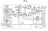
- FIG. 1illustrates a block diagram of an exemplary motor controller in accordance with the present invention
- FIG. 2is a graph showing a d-axis saturation curve for a typical SMPMS machine
- FIG. 3is a graph showing a q-axis saturation curve for a typical SMPMS machine
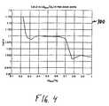
- FIG. 4is a graph showing the ratio L q /L d at peak torque points for the typical SMPMS machine characterized by the graphs of FIGS. 2-3;
- FIGS. 5-8are signal traces showing the operational results of an exemplary SMPMS motor that is controlled by the motor controller of FIG. 1 .
- R, L d , and L qare the stator resistance and d-axis and q-axis inductance
- ⁇ eis the electrical speed of magnetic field
- Pis the number of poles
- ⁇ mis the flux linkage of permanent magnets
- i dis the flux generating component of the stator current
- i qis the torque generating component of the stator current.
- V maxis the maximum available phase voltage amplitude at the fundamental frequency
- I maxis the maximum phase current
- i d ref- ⁇ m L d + ( V max ⁇ c ⁇ L d ) 2 - ( L q L d ⁇ ⁇ i q ref ) 2 , ( 6 )
- T refis the reference torque value, and is typically obtained from the vehicle controller.
- L dL q .
- Typical L d and L q saturation curves vs. i d and i qrespectively are shown in the graphs 200 , 300 of FIGS. 2-3.
- a graph 400 of the L q /L d ratio at peak torque points vs. ⁇ base / ⁇ eis shown in FIG. 4, where ⁇ base . represents the base motor speed and ⁇ e represents the actual motor speed.
- FIG. 1a control block diagram of an exemplary SMPMS drive 10 in accordance with an embodiment of the present invention is shown.
- the drive 10can be implemented using various electronic and/or software components, it is preferably implemented using a microprocessor, such as a digital signal processor (DSP) 12 interfaced to a commercially-available inverter 13 and SMPMS motor 14 .
- DSPdigital signal processor
- elements 16 - 52 of the control blockcan be software program routines, such as assembly code routines, executable by the DSP 12 .
- the DSP 12can be any suitable commercially-available DSP, such as part no. ADSP 2171, available from Analog Devices, Inc.
- the flux weakening block 16generates i d ref and i q ref references so that constraints given by Eq. (4) are always satisfied.
- Two controllers 44 , 46such as anti-windup proportional-integral (PI) controllers, in the synchronous reference frame are used for current control, although different types of current controllers can be used as well.
- a space vector modulator (SVM) 50with smooth transition from sine wave to a full six-step operation, is employed to generate IGBT gate signals, but other types of pulse width modulation techniques (PWM) can also be employed.
- PWMpulse width modulation techniques
- the space vector modulator (SVM)reduces IGBT switching losses, while full six-step operation enables maximum DC bus voltage utilization, which is important in applications where it is necessary to maximize the torque available, for example, in electrical propulsion.
- the sum of the squares for i q1 * and i d1 *is computed (step 22 ) and compared to the maximal current squared, I max 2 (step 24 ). If the current limit is satisfied, i q1 * and i d1 * from Eqs. (5)-(6), are used as references for the current regulators (step 30 ). If not, Eqs. (7) and (8) are used instead to calculate i q2 * and i d2 * (step 26 ) and i q2 * and i d2 * are used as references for the current regulators (step 28 ).
- This feedback termprovides stable and fast torque transient response, although is practically zero in steady-state operation of the motor 14 , i.e., the system does not need the torque current error to produce the magnetizing current reference in steady-state.
- the feedback termis generated by a feedback path that includes elements 32 - 38 , 42 .
- the electrical speed feedback signal ⁇ eis arithmetically combined with a predetermined constant K, preferably using a multiplication operation (step 32 ).
- Kpreferably used to be in the range of five to ten for stable operation.
- the weighted electrical speed signalis multiplied by a torque current error e q by a multiplier 34 .
- the torque current erroris the difference between the torque reference current i q * and a feedback torque current i q from the permanent magnet motor 14 .
- a limiter 36is provided for limiting the feedback term to a predetermined range, such as a positive value.
- a pair of subtractors 40 , 42output the magnetizing and torque current errors, respectively, which are provided to the respective PI controllers 44 , 46 .
- the PI controllerscan incorporate motor back-emf decoupling terms, gain correction with V batt and anti-windup integrator limiting, as described in Maric 1998.
- Coordinate transform routines 48 , 52are provided for transforming drive and feedback signals between rotating reference and stationary reference frames.
- the motor 14can be a three-phase SMPMS motor having a 14 kW peak output and capable of operating at 4500 RPM and 900 Hz.
- FIGS. 5-8are signal traces showing the operational results of the exemplary SMPMS motor 14 that is controlled using the scheme of FIG. 1 .
- a graph 500is shown for the transient from ⁇ 100% to 100% torque.
- the d-axis currentis represented by trace 502
- the input torque current commandis represented by trace 506
- the actual torque current i qis represented by trace 504 .
- a slight decrease of the d-axis currentcan be detected during the transient, which contributes to the temporary reduction of the back e.m.f. of the motor and allows for the rapid change of q-axis current.
- FIG. 6presents a graph 600 of a similar type of transient, but in the opposite direction from that of FIG. 5, from full motoring to maximum regeneration.
- the d-axis currentis represented by trace 602
- the input torque current commandis represented by trace 606
- the actual torque current i qis represented by trace 604 .
- FIGS. 7-8are graphs 700 , 800 that present torque transient operation above base speed (at 3500 rpm, 250 Vdc), where the control voltage margin is greatly reduced.
- the d-axis currentis represented by traces 702 , 802
- the input torque current commandis represented by traces 706 , 806
- the actual torque current i qis represented by traces 704 , 804 .
Landscapes
- Engineering & Computer Science (AREA)
- Power Engineering (AREA)
- Transportation (AREA)
- Mechanical Engineering (AREA)
- Control Of Ac Motors In General (AREA)
Abstract
Description


Claims (13)
Priority Applications (1)
| Application Number | Priority Date | Filing Date | Title |
|---|---|---|---|
| US09/829,106US6504329B2 (en) | 2001-04-09 | 2001-04-09 | Apparatus and method for controlling permanent magnet electric machines |
Applications Claiming Priority (1)
| Application Number | Priority Date | Filing Date | Title |
|---|---|---|---|
| US09/829,106US6504329B2 (en) | 2001-04-09 | 2001-04-09 | Apparatus and method for controlling permanent magnet electric machines |
Publications (2)
| Publication Number | Publication Date |
|---|---|
| US20020171387A1 US20020171387A1 (en) | 2002-11-21 |
| US6504329B2true US6504329B2 (en) | 2003-01-07 |
Family
ID=25253541
Family Applications (1)
| Application Number | Title | Priority Date | Filing Date |
|---|---|---|---|
| US09/829,106Expired - Fee RelatedUS6504329B2 (en) | 2001-04-09 | 2001-04-09 | Apparatus and method for controlling permanent magnet electric machines |
Country Status (1)
| Country | Link |
|---|---|
| US (1) | US6504329B2 (en) |
Cited By (13)
| Publication number | Priority date | Publication date | Assignee | Title |
|---|---|---|---|---|
| US20040036434A1 (en)* | 2002-06-03 | 2004-02-26 | Ballard Power Systems Corporation | Method and apparatus for motor control |
| US20040100221A1 (en)* | 2002-11-25 | 2004-05-27 | Zhenxing Fu | Field weakening with full range torque control for synchronous machines |
| US20050029982A1 (en)* | 2003-08-05 | 2005-02-10 | Stancu Constantin C. | Methods and apparatus for current control of a three-phase voltage source inverter in the overmodulation region |
| US20050046375A1 (en)* | 2002-07-31 | 2005-03-03 | Maslov Boris A. | Software-based adaptive control system for electric motors and generators |
| US20050057208A1 (en)* | 2003-09-17 | 2005-03-17 | Seibel Brian J. | Method and apparatus to regulate loads |
| US6965212B1 (en) | 2004-11-30 | 2005-11-15 | Honeywell International Inc. | Method and apparatus for field weakening control in an AC motor drive system |
| US20060055363A1 (en)* | 2004-09-13 | 2006-03-16 | Patel Nitinkumar R | Field weakening motor control system and method |
| US20080116842A1 (en)* | 2006-11-17 | 2008-05-22 | Bing Cheng | Method and apparatus for motor control |
| US20090212734A1 (en)* | 2008-02-22 | 2009-08-27 | Rockwell Automation Technologies, Inc. | Torque limit of pm motors for field-weakening region operation |
| US20130026959A1 (en)* | 2011-07-26 | 2013-01-31 | Fanuc Corporation | Control device that detects whether or not irreversible demagnetization has occurred in permanent magnet of permanent magnet synchronous motor |
| US20130049363A1 (en)* | 2011-08-31 | 2013-02-28 | General Electric Company | Permanent magnet machine control system |
| US8676386B2 (en) | 2011-08-31 | 2014-03-18 | General Electric Company | Fault detection system for a generator |
| US20160006385A1 (en)* | 2014-07-02 | 2016-01-07 | Hyundai Motor Company | Control device and method for improving voltage utilization ratio of inverter for green car |
Families Citing this family (10)
| Publication number | Priority date | Publication date | Assignee | Title |
|---|---|---|---|---|
| US7002317B2 (en)* | 2004-02-18 | 2006-02-21 | Honeywell International Inc. | Matched reactance machine power-generation system |
| JP5742020B2 (en)* | 2011-07-04 | 2015-07-01 | 西芝電機株式会社 | Electric propulsion device for ships |
| US9271367B2 (en) | 2012-07-09 | 2016-02-23 | Ilumisys, Inc. | System and method for controlling operation of an LED-based light |
| US20140285124A1 (en)* | 2013-03-12 | 2014-09-25 | Universiteit Gent | Control method and device therefor |
| JP5620535B2 (en) | 2013-03-19 | 2014-11-05 | ファナック株式会社 | Motor control system that detects voltage saturation |
| US9667265B2 (en) | 2015-08-11 | 2017-05-30 | Semiconductor Components Industries, Llc | Method of forming an amplifier and structure therefor |
| US10038447B2 (en) | 2015-08-11 | 2018-07-31 | Semiconductor Components Industries, Llc | Method of forming a semiconductor device and structure therefor |
| US11591009B2 (en)* | 2019-11-25 | 2023-02-28 | Steering Solutions Ip Holding Corporation | Power management of permanent magnet synchronous motor (PMSM) drive using machine current limiting |
| CN117999736A (en)* | 2021-07-07 | 2024-05-07 | 塔乌电机股份有限公司 | System and method for controlling an electric machine |
| CN114629395B (en)* | 2022-03-16 | 2024-04-26 | 北京理工大学 | A motor driving method without current sensor |
Citations (9)
| Publication number | Priority date | Publication date | Assignee | Title |
|---|---|---|---|---|
| US3862856A (en)* | 1972-06-29 | 1975-01-28 | Headway Research Inc | Method for achieving thin films on substrates |
| US4916368A (en)* | 1987-11-14 | 1990-04-10 | Hitachi Elevator Engineering & Service Company, Ltd. | Controlling method and device for permanent magnet synchronous motor |
| US5504404A (en)* | 1993-09-17 | 1996-04-02 | Matsushita Electric Industrial Co., Ltd. | Method and apparatus for controlling motor |
| US5656911A (en)* | 1994-12-27 | 1997-08-12 | Fuji Electric Company | Circuit for driving permanent-magnet synchronous motor using proportional controller |
| US5739664A (en)* | 1996-02-05 | 1998-04-14 | Ford Global Technologies, Inc. | Induction motor drive controller |
| US6002234A (en)* | 1995-06-05 | 1999-12-14 | Kollmorgen Corporation | System and method for controlling brushless permanent magnet motors |
| US6163128A (en)* | 1999-08-20 | 2000-12-19 | General Motors Corporation | Method and drive system for controlling a permanent magnet synchronous machine |
| US6288515B1 (en)* | 2000-04-19 | 2001-09-11 | General Motors Corporation | System and method for controlling a surface-mounted permanent magnet synchronous machine drive over a wide speed range using a reference voltage |
| US6304052B1 (en)* | 2000-06-27 | 2001-10-16 | General Motors Corporation | Control system for a permanent magnet motor |
- 2001
- 2001-04-09USUS09/829,106patent/US6504329B2/ennot_activeExpired - Fee Related
Patent Citations (9)
| Publication number | Priority date | Publication date | Assignee | Title |
|---|---|---|---|---|
| US3862856A (en)* | 1972-06-29 | 1975-01-28 | Headway Research Inc | Method for achieving thin films on substrates |
| US4916368A (en)* | 1987-11-14 | 1990-04-10 | Hitachi Elevator Engineering & Service Company, Ltd. | Controlling method and device for permanent magnet synchronous motor |
| US5504404A (en)* | 1993-09-17 | 1996-04-02 | Matsushita Electric Industrial Co., Ltd. | Method and apparatus for controlling motor |
| US5656911A (en)* | 1994-12-27 | 1997-08-12 | Fuji Electric Company | Circuit for driving permanent-magnet synchronous motor using proportional controller |
| US6002234A (en)* | 1995-06-05 | 1999-12-14 | Kollmorgen Corporation | System and method for controlling brushless permanent magnet motors |
| US5739664A (en)* | 1996-02-05 | 1998-04-14 | Ford Global Technologies, Inc. | Induction motor drive controller |
| US6163128A (en)* | 1999-08-20 | 2000-12-19 | General Motors Corporation | Method and drive system for controlling a permanent magnet synchronous machine |
| US6288515B1 (en)* | 2000-04-19 | 2001-09-11 | General Motors Corporation | System and method for controlling a surface-mounted permanent magnet synchronous machine drive over a wide speed range using a reference voltage |
| US6304052B1 (en)* | 2000-06-27 | 2001-10-16 | General Motors Corporation | Control system for a permanent magnet motor |
Non-Patent Citations (7)
| Title |
|---|
| Authors, CHOI et al., Article entitled "Design of Fast-Response Current Controller Using d-q Axis Cross Coupling: Application to Permanent Magnet Synchronous Motor Drive," IEEE Transactions on Industrial Electronics, (Dated Jun. 1998, pp. 522-524, vol. 45, No. 3). |
| Authors, Dragan S. Maric, Article entitled "Two Improved Flux Weakening Schemes for Surface Mounted Permanent Magnet Sychronous Machine Drives Employing Space Vector Modulation", California Institute of Technology, Department of Electrical Engineering, M/S 136-93, (Dated 1998 IEEE, pp. 508-512). |
| Authors, Maric et al., Article entitled "Robust Flux Weakening Scheme for Surface-Mounted Permanent-Magnet Synchronous Drives Employing an Adaptive Lattice-Structure Filter," California Institute of Technology, Dept. of Electrical Engineering, M/S 136-93 (Dated (C)1999, IEEE, pp. 271-276). |
| Authors, Maric et al., Article entitled "Robust Flux Weakening Scheme for Surface-Mounted Permanent-Magnet Synchronous Drives Employing an Adaptive Lattice-Structure Filter," California Institute of Technology, Dept. of Electrical Engineering, M/S 136-93 (Dated ©1999, IEEE, pp. 271-276). |
| Authors, Song et al., Article entitled "A New Robust SPMSM Control to Parameter Variations in Flux Weakening Region", Hyosung Industry Co., Ltd., Dangsan-Dong Yeongdeungpo-Ku, Seoul, Korea, School of Electrical Engineering, Seoul National University (Dated (C)1996 IEEE, pp. 1193-1198). |
| Authors, Song et al., Article entitled "A New Robust SPMSM Control to Parameter Variations in Flux Weakening Region", Hyosung Industry Co., Ltd., Dangsan-Dong Yeongdeungpo-Ku, Seoul, Korea, School of Electrical Engineering, Seoul National University (Dated ©1996 IEEE, pp. 1193-1198). |
| Authors, Sudhoff et al., Article entitled "A Flux-Weakening Strategy for Current-Regulated Surface-Mounted Permanent-Magnet Machine Drives", School of Electrical Engineering, University of Missouri-Rolla, Naval Surface Warfare Center, Annapolis Detachment, Carderock Division, IEEE Transactions on Energy Conversion, (Dated Sep. 1995, pp. 431-437, vol. 10, No. 3). |
Cited By (22)
| Publication number | Priority date | Publication date | Assignee | Title |
|---|---|---|---|---|
| US6936991B2 (en)* | 2002-06-03 | 2005-08-30 | Ballard Power Systems Corporation | Method and apparatus for motor control |
| US20040036434A1 (en)* | 2002-06-03 | 2004-02-26 | Ballard Power Systems Corporation | Method and apparatus for motor control |
| US20050046375A1 (en)* | 2002-07-31 | 2005-03-03 | Maslov Boris A. | Software-based adaptive control system for electric motors and generators |
| US20040100221A1 (en)* | 2002-11-25 | 2004-05-27 | Zhenxing Fu | Field weakening with full range torque control for synchronous machines |
| US6984960B2 (en) | 2003-08-05 | 2006-01-10 | General Motors Corporation | Methods and apparatus for current control of a three-phase voltage source inverter in the overmodulation region |
| US20050029982A1 (en)* | 2003-08-05 | 2005-02-10 | Stancu Constantin C. | Methods and apparatus for current control of a three-phase voltage source inverter in the overmodulation region |
| US20050057208A1 (en)* | 2003-09-17 | 2005-03-17 | Seibel Brian J. | Method and apparatus to regulate loads |
| US6982533B2 (en)* | 2003-09-17 | 2006-01-03 | Rockwell Automation Technologies, Inc. | Method and apparatus to regulate loads |
| US7023168B1 (en)* | 2004-09-13 | 2006-04-04 | General Motors Corporation | Field weakening motor control system and method |
| US20060055363A1 (en)* | 2004-09-13 | 2006-03-16 | Patel Nitinkumar R | Field weakening motor control system and method |
| US6965212B1 (en) | 2004-11-30 | 2005-11-15 | Honeywell International Inc. | Method and apparatus for field weakening control in an AC motor drive system |
| US20080116842A1 (en)* | 2006-11-17 | 2008-05-22 | Bing Cheng | Method and apparatus for motor control |
| US7586286B2 (en) | 2006-11-17 | 2009-09-08 | Continental Automotive Systems Us, Inc. | Method and apparatus for motor control |
| US20090212734A1 (en)* | 2008-02-22 | 2009-08-27 | Rockwell Automation Technologies, Inc. | Torque limit of pm motors for field-weakening region operation |
| US8115437B2 (en)* | 2008-02-22 | 2012-02-14 | Rockwell Automation Technologies, Inc. | Torque limit of PM motors for field-weakening region operation |
| US20130026959A1 (en)* | 2011-07-26 | 2013-01-31 | Fanuc Corporation | Control device that detects whether or not irreversible demagnetization has occurred in permanent magnet of permanent magnet synchronous motor |
| US8633663B2 (en)* | 2011-07-26 | 2014-01-21 | Fanuc Corporation | Control device that detects whether or not irreversible demagnetization has occurred in permanent magnet of permanent magnet synchronous motor |
| US20130049363A1 (en)* | 2011-08-31 | 2013-02-28 | General Electric Company | Permanent magnet machine control system |
| US8575772B2 (en)* | 2011-08-31 | 2013-11-05 | General Electric Company | Permanent magnet machine control system |
| US8676386B2 (en) | 2011-08-31 | 2014-03-18 | General Electric Company | Fault detection system for a generator |
| US20160006385A1 (en)* | 2014-07-02 | 2016-01-07 | Hyundai Motor Company | Control device and method for improving voltage utilization ratio of inverter for green car |
| US9584057B2 (en)* | 2014-07-02 | 2017-02-28 | Hyundai Motor Company | Control device and method for improving voltage utilization ratio of inverter for green car |
Also Published As
| Publication number | Publication date |
|---|---|
| US20020171387A1 (en) | 2002-11-21 |
Similar Documents
| Publication | Publication Date | Title |
|---|---|---|
| US6504329B2 (en) | Apparatus and method for controlling permanent magnet electric machines | |
| CN100561854C (en) | Magnetic-field-weakening motor control system | |
| JP3746377B2 (en) | AC motor drive control device | |
| CN101529714B (en) | Vector Control Device of Permanent Magnet Synchronous Motor | |
| US7595600B2 (en) | Method and system for torque control in permanent magnet machines | |
| US7923953B2 (en) | Linearity for field weakening in an interior permanent magnet machine | |
| JP5246508B2 (en) | Control device for motor drive device | |
| JP3627683B2 (en) | Motor control device | |
| US8228016B2 (en) | Gain adjustment to improve torque linearity in a field weakening region | |
| US8285451B2 (en) | Method and apparatus for controlling electric power steering system | |
| US6690137B2 (en) | Sensorless control system for synchronous motor | |
| JP4715576B2 (en) | Electric drive control device and electric drive control method | |
| US20050046370A1 (en) | System and method for clamp current regulation in field-weakening operation of permanent magnet (PM) machines | |
| US8760098B2 (en) | Sensorless motor control | |
| JP3674741B2 (en) | Control device for permanent magnet synchronous motor | |
| US6707266B2 (en) | Motor control device | |
| Foo et al. | Robust constant switching frequency-based field-weakening algorithm for direct torque controlled reluctance synchronous motors | |
| JP5204463B2 (en) | Motor control device | |
| JPH08275599A (en) | Control method for permanent magnet synchronous motor | |
| Kwon et al. | A novel flux weakening algorithm for surface mounted permanent magnet synchronous machines with infinite constant power speed ratio | |
| US20230291341A1 (en) | Rotating electrical machine control system | |
| Maric et al. | Two improved flux weakening schemes for surface mounted permanent magnet synchronous machine drives employing space vector modulation | |
| JP3687043B2 (en) | Control method of synchronous motor | |
| JP3290099B2 (en) | Control device for reluctance type synchronous motor | |
| JP7629818B2 (en) | AC motor drive control device and drive control method |
Legal Events
| Date | Code | Title | Description |
|---|---|---|---|
| AS | Assignment | Owner name:GENERAL MOTORS CORPORATION, MICHIGAN Free format text:ASSIGNMENT OF ASSIGNORS INTEREST;ASSIGNORS:STANCU, CONSTANTIN C.;HITI, SILVA;NAGASHIMA, JAMES M.;REEL/FRAME:011755/0598 Effective date:20010406 | |
| FPAY | Fee payment | Year of fee payment:4 | |
| AS | Assignment | Owner name:GM GLOBAL TECHNOLOGY OPERATIONS, INC., MICHIGAN Free format text:ASSIGNMENT OF ASSIGNORS INTEREST;ASSIGNOR:GENERAL MOTORS CORPORATION;REEL/FRAME:022092/0703 Effective date:20050119 Owner name:GM GLOBAL TECHNOLOGY OPERATIONS, INC.,MICHIGAN Free format text:ASSIGNMENT OF ASSIGNORS INTEREST;ASSIGNOR:GENERAL MOTORS CORPORATION;REEL/FRAME:022092/0703 Effective date:20050119 | |
| AS | Assignment | Owner name:UNITED STATES DEPARTMENT OF THE TREASURY, DISTRICT Free format text:SECURITY AGREEMENT;ASSIGNOR:GM GLOBAL TECHNOLOGY OPERATIONS, INC.;REEL/FRAME:022201/0501 Effective date:20081231 | |
| AS | Assignment | Owner name:CITICORP USA, INC. AS AGENT FOR HEDGE PRIORITY SEC Free format text:SECURITY AGREEMENT;ASSIGNOR:GM GLOBAL TECHNOLOGY OPERATIONS, INC.;REEL/FRAME:022556/0013 Effective date:20090409 Owner name:CITICORP USA, INC. AS AGENT FOR BANK PRIORITY SECU Free format text:SECURITY AGREEMENT;ASSIGNOR:GM GLOBAL TECHNOLOGY OPERATIONS, INC.;REEL/FRAME:022556/0013 Effective date:20090409 | |
| AS | Assignment | Owner name:GM GLOBAL TECHNOLOGY OPERATIONS, INC., MICHIGAN Free format text:RELEASE BY SECURED PARTY;ASSIGNOR:UNITED STATES DEPARTMENT OF THE TREASURY;REEL/FRAME:023238/0015 Effective date:20090709 | |
| XAS | Not any more in us assignment database | Free format text:RELEASE BY SECURED PARTY;ASSIGNOR:UNITED STATES DEPARTMENT OF THE TREASURY;REEL/FRAME:023124/0383 | |
| AS | Assignment | Owner name:GM GLOBAL TECHNOLOGY OPERATIONS, INC., MICHIGAN Free format text:RELEASE BY SECURED PARTY;ASSIGNORS:CITICORP USA, INC. AS AGENT FOR BANK PRIORITY SECURED PARTIES;CITICORP USA, INC. AS AGENT FOR HEDGE PRIORITY SECURED PARTIES;REEL/FRAME:023127/0326 Effective date:20090814 | |
| AS | Assignment | Owner name:UNITED STATES DEPARTMENT OF THE TREASURY, DISTRICT Free format text:SECURITY AGREEMENT;ASSIGNOR:GM GLOBAL TECHNOLOGY OPERATIONS, INC.;REEL/FRAME:023155/0922 Effective date:20090710 | |
| AS | Assignment | Owner name:UAW RETIREE MEDICAL BENEFITS TRUST, MICHIGAN Free format text:SECURITY AGREEMENT;ASSIGNOR:GM GLOBAL TECHNOLOGY OPERATIONS, INC.;REEL/FRAME:023161/0864 Effective date:20090710 | |
| FPAY | Fee payment | Year of fee payment:8 | |
| AS | Assignment | Owner name:GM GLOBAL TECHNOLOGY OPERATIONS, INC., MICHIGAN Free format text:RELEASE BY SECURED PARTY;ASSIGNOR:UAW RETIREE MEDICAL BENEFITS TRUST;REEL/FRAME:025311/0680 Effective date:20101026 Owner name:GM GLOBAL TECHNOLOGY OPERATIONS, INC., MICHIGAN Free format text:RELEASE BY SECURED PARTY;ASSIGNOR:UNITED STATES DEPARTMENT OF THE TREASURY;REEL/FRAME:025245/0273 Effective date:20100420 | |
| AS | Assignment | Owner name:WILMINGTON TRUST COMPANY, DELAWARE Free format text:SECURITY AGREEMENT;ASSIGNOR:GM GLOBAL TECHNOLOGY OPERATIONS, INC.;REEL/FRAME:025327/0222 Effective date:20101027 | |
| AS | Assignment | Owner name:GM GLOBAL TECHNOLOGY OPERATIONS LLC, MICHIGAN Free format text:CHANGE OF NAME;ASSIGNOR:GM GLOBAL TECHNOLOGY OPERATIONS, INC.;REEL/FRAME:025780/0795 Effective date:20101202 | |
| REMI | Maintenance fee reminder mailed | ||
| LAPS | Lapse for failure to pay maintenance fees | ||
| STCH | Information on status: patent discontinuation | Free format text:PATENT EXPIRED DUE TO NONPAYMENT OF MAINTENANCE FEES UNDER 37 CFR 1.362 | |
| FP | Lapsed due to failure to pay maintenance fee | Effective date:20150107 |