US6503262B1 - Retractable micro-surgical tool - Google Patents
Retractable micro-surgical toolDownload PDFInfo
- Publication number
- US6503262B1 US6503262B1US09/707,641US70764100AUS6503262B1US 6503262 B1US6503262 B1US 6503262B1US 70764100 AUS70764100 AUS 70764100AUS 6503262 B1US6503262 B1US 6503262B1
- Authority
- US
- United States
- Prior art keywords
- shell
- surgical tool
- cantilever arm
- slot
- button
- Prior art date
- Legal status (The legal status is an assumption and is not a legal conclusion. Google has not performed a legal analysis and makes no representation as to the accuracy of the status listed.)
- Expired - Fee Related, expires
Links
- 230000003247decreasing effectEffects0.000claimsdescription12
- 238000002406microsurgeryMethods0.000abstractdescription5
- 210000003811fingerAnatomy0.000description3
- 238000012986modificationMethods0.000description2
- 230000004048modificationEffects0.000description2
- 208000027418Wounds and injuryDiseases0.000description1
- 239000000853adhesiveSubstances0.000description1
- 230000001070adhesive effectEffects0.000description1
- 230000004323axial lengthEffects0.000description1
- 230000006378damageEffects0.000description1
- 230000000994depressogenic effectEffects0.000description1
- 208000014674injuryDiseases0.000description1
- 238000003780insertionMethods0.000description1
- 230000037431insertionEffects0.000description1
- 238000000034methodMethods0.000description1
- 230000000717retained effectEffects0.000description1
- 210000003813thumbAnatomy0.000description1
- 238000003466weldingMethods0.000description1
Images


Classifications
- A—HUMAN NECESSITIES
- A61—MEDICAL OR VETERINARY SCIENCE; HYGIENE
- A61F—FILTERS IMPLANTABLE INTO BLOOD VESSELS; PROSTHESES; DEVICES PROVIDING PATENCY TO, OR PREVENTING COLLAPSING OF, TUBULAR STRUCTURES OF THE BODY, e.g. STENTS; ORTHOPAEDIC, NURSING OR CONTRACEPTIVE DEVICES; FOMENTATION; TREATMENT OR PROTECTION OF EYES OR EARS; BANDAGES, DRESSINGS OR ABSORBENT PADS; FIRST-AID KITS
- A61F9/00—Methods or devices for treatment of the eyes; Devices for putting in contact-lenses; Devices to correct squinting; Apparatus to guide the blind; Protective devices for the eyes, carried on the body or in the hand
- A61F9/007—Methods or devices for eye surgery
- A61F9/013—Instruments for compensation of ocular refraction ; Instruments for use in cornea removal, for reshaping or performing incisions in the cornea
- A61F9/0133—Knives or scalpels specially adapted therefor
- A—HUMAN NECESSITIES
- A61—MEDICAL OR VETERINARY SCIENCE; HYGIENE
- A61B—DIAGNOSIS; SURGERY; IDENTIFICATION
- A61B17/00—Surgical instruments, devices or methods
- A61B17/32—Surgical cutting instruments
- A61B17/3209—Incision instruments
- A61B17/3211—Surgical scalpels, knives; Accessories therefor
- A61B2017/32113—Surgical scalpels, knives; Accessories therefor with extendable or retractable guard or blade
Definitions
- the present inventionrelates generally to surgical tools and more specifically to a retractable micro-surgical tool having various uses.
- a retractable micro-surgical toolwhich has a cutting blade small enough for micro-surgery applications, may be securely locked in an extended position, and may be retracted to protect handlers from being cut by the blade.
- the present inventionprovides a retractable micro-surgical tool which requires a deliberate action to release the blade from an extended position.
- the retractable micro-surgical toolincludes a shell, slidable insert, slide button, spring, and blade.
- the shellis preferably a hollow tube which comes to a decreasing taper at a first end thereof.
- a first slotis formed through the wall of the shell at substantially a first end thereof.
- a second slotis formed through the wall of the shell at substantially a middle of the shell length.
- a connecting slotis formed through the wall of the shell and enables the slide button to be slid between the first and second slots.
- the slidable insertincludes a body, a first cantilever arm, and a second cantilever arm.
- a first end of the bodyis tapered to fit inside the first end of the shell.
- the bladeis retained in the first end of the body.
- An end of the blademay have different shaped cutting edges such as a spear, vetrectomy, lance, trifacet, or any other shape which is suitable for performing micro-surgery.
- the first cantilever armextends from substantially a middle of the body and the second cantilever arm extends from an end of the first cantilever arm.
- the slide buttonis attached to a top of the second cantilever arm at assembly.
- At least one side of the bodyhas a groove formed therein to provide clearance for the spring.
- a holeis formed through a middle of the body for attachment of one end of the spring.
- An end plugis inserted into a second end of the shell.
- An end of the end plughas a hole formed therethrough for attachment of the other end of the spring
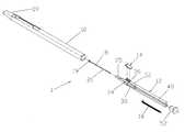
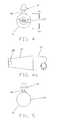
- FIG. 1is an exploded perspective view of a retractable micro-surgical tool in accordance with the present invention.
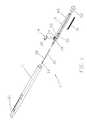
- FIG. 2is a top view of a retractable micro-surgical tool with the blade in a retracted position in accordance with the present invention.
- FIG. 3is a top view of a retractable micro-surgical tool with the blade in an extended position in accordance with the present invention.
- FIG. 4is an enlarged front end view of a retractable micro-surgical tool in accordance with the present invention.
- FIG. 4 ais an enlarged partial side view of a front of a retractable micro-surgical tool in accordance with the present invention.
- FIG. 5is an enlarged rear end view of a retractable micro-surgical tool in accordance with the present invention.
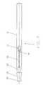
- FIG. 6is an enlarged cross sectional side view of a slide button of a retractable micro-surgical tool locked in a first slot in accordance with the present invention.
- FIG. 7is an enlarged cross sectional side view of a slide button of a retractable micro-surgical tool unlocked in a first slot in accordance with the present invention.
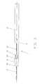
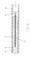
- FIG. 8is a side cross sectional view of a spring pulling a slidable insert of a retractable micro-surgical tool in accordance with the present invention.
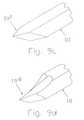
- FIG. 9 ais an enlarged perspective view of a spear cutting edge for a retractable micro-surgical tool in accordance with the present invention.
- FIG. 9 bis an enlarged perspective view of a vetrectomy cutting edge for a retractable micro-surgical tool in accordance with the present invention.
- FIG. 9 cis an enlarged perspective view of an extended vetrectomy cutting edge for a retractable micro-surgical tool in accordance with the present invention.
- FIG. 9 dis an enlarged perspective view of a lance cutting edge for a retractable micro-surgical tool in accordance with the present invention.
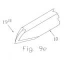
- FIG. 9 eis an enlarged perspective view of a trifacet cutting edge for a retractable micro-surgical tool in accordance with the present invention.
- the retractable micro-surgical tool 1includes a shell 10 , slidable insert 12 , slide button 14 , spring 16 , and blade 18 .
- the shell 10is preferably a hollow tube.
- the shape of the shell 10should not be limited to a round shape, but could also be square or any other shape.
- the inner diametercould also be a square or any other shaped opening.
- a decreasing taper 20is preferably formed on a first end of the shell 10 .
- An outer periphery of the slidable insert 12is slidable along the length of the inner diameter of the shell 10 .
- a first slot 22is formed through a top of the shell 10 at substantially a first end thereof.
- a second slot 24is formed through the top of the shell 10 at substantially a middle of the axial length of the shell.
- a connecting slot 26is formed through the wall of the shell 10 between the first and second slots, such that the slide button 14 may be slid between the first and second slots.
- a pair of opposing projections 28preferably extend outward from a front of the decreasing taper 20 . Each edge of the blade 18 is aligned with each of the opposing projections 28 .
- the slidable insert 12includes a body 30 , a first cantilever arm 32 , and a second cantilever arm 34 .
- a spear cutting edge 19is formed on a first end of the blade 18 and a shank 21 is formed on a second end of the blade 18 .
- the shank 21may have a cross section which is round, square or any other suitable shape to accommodate a particular cutting edge type or style.
- a first end of the body 30has a shank retainer 35 which is sized to securely retain the shank 21 of the blade 18 and to fit inside the decreasing taper 20 of the shell 10 .
- a shank openingis preferably formed in the shank retainer 35 for insertion of the shank 21 .
- an interference fitis formed between the shank 21 and the shank opening in the shank retainer 35 .
- the blade 18could also be molded inside the shank retainer 35 , or attached through any other appropriate assembly method such as sonic welding, application of adhesive, or threads.
- the first cantilever arm 32extends from substantially a middle of the body 30 and the second cantilever arm 34 extends from an end of the first cantilever arm 32 .
- the junction 38 between the first cantilever arm 32 and the second cantilever arm 34must be more flexible than the first cantilever arm 32 to allow the button 14 to be disengaged from the first slot 22 .
- a cutout 45is preferably formed adjacent the junction 38 to allow the flexibility thereof to be changed by reducing the size of the cutout 45 .
- the button 14includes relieved sides 40 , a pair of locking pins 42 , and a finger projection 46 .
- the relieved sides 40are sized to slidably fit in the connecting slot 26 .
- the pair of locking pins 42fit in a pair of holes 36 formed in the second cantilever member 34 .
- An enlarged head 44 at the end of each locking pin 42ensures that the button 14 remains secured to the second cantilever arm 34 .
- the second end 23 of the first slot 22must be angled toward a second end of the shell 10 to prevent accidental disengagement of the button 14 from the first slot 22 .
- a rear of the junction 38 and a second end 41 of the button 14must also be angled toward a second end of the shell 10 to match the second end 23 of the first slot 22 .
- Extending the blade 18requires a front of the button 14 to be pushed down (depressed) and forward until a second end 41 of the button 14 clears the second end 23 of the first slot 22 . Thumb or finger pressure on the button 14 is then released and the blade 18 is securely extended; since the first cantilever arm 32 is less flexible than the junction 38 , the second end 41 of the button 14 will lock into the second end 23 of the first slot 22 , before forward pressure on the button 14 is released; thus enabling the button 14 to be latched, before the spring 16 retracts.
- the finger projection 46is preferably used to slide the button 14 . Releasing the button 14 from the first slot 22 requires that the button 14 be pushed forward and then down.
- the second end 23 of the first slot 22 , junction 38 , and second end 41 of the button 14make it necessary to push the button 14 forward to release the blade 18 from the extended position and thus ensure that the blade 18 is secure while in the extended position.
- the slidable insert 12will slide back to the second slot 24 and the button 14 will automatically lock itself in the second slot 24 .
- FIG. 8discloses the spring 16 pulling the slidable insert 12 backward toward the second end of the shell 10 .
- At least one groove 48is formed along a second end of the slidable insert 12 to provide clearance for the spring 16 .
- the spring 16is preferably an extension spring.
- a spring hole 50is formed through a middle of the body 30 for attachment of one end of the spring 16 .
- An end plug 52is inserted into a second end of the shell 10 .
- An end of the end plughas a hole 54 formed therethrough for attachment of the other end of the spring 16 .
- the spring 16retains the blade 18 in a retracted position and automatically retracts the blade 18 from the extended position when the button 14 is released from the first slot 22 .
- the spring 16also pulls the button 14 backwards to secure the blade 18 in the extended position.
- FIGS. 9 b - 9 edisclose several different styles of cutting edges which may be substituted for the spear cutting edge 19 disclosed in FIGS. 1-9 a .
- An enlarged vetrectomy cutting edge 19 ′is disclosed in FIG. 9 b .
- An enlarged lance cutting edge 19 ′′is disclosed in FIG. 9 c .
- An enlarged extended vetrectomy cutting edge 19 ′′′is disclosed in FIG. 9 d .
- An enlarged trifacet cutting edge 19 ′′′′is disclosed in FIG. 9 e .
- Other cutting edges suitable for performing micro-surgery besides those disclosed abovemay also be formed on the end of the blade 18 .
Landscapes
- Health & Medical Sciences (AREA)
- Ophthalmology & Optometry (AREA)
- Heart & Thoracic Surgery (AREA)
- Surgery (AREA)
- Engineering & Computer Science (AREA)
- Biomedical Technology (AREA)
- Nuclear Medicine, Radiotherapy & Molecular Imaging (AREA)
- Vascular Medicine (AREA)
- Life Sciences & Earth Sciences (AREA)
- Animal Behavior & Ethology (AREA)
- General Health & Medical Sciences (AREA)
- Public Health (AREA)
- Veterinary Medicine (AREA)
- Surgical Instruments (AREA)
Abstract
Description
This is a continuation-in-part application taking priority from Ser. No. 09/619,120 filed on Jul. 19, 2000.
1. Field of the Invention
The present invention relates generally to surgical tools and more specifically to a retractable micro-surgical tool having various uses.
2. Discussion of the Prior Art
There are numerous patents which disclose retractable scalpel blades for making incisions. However, these blades are too large for micro-surgery. There is a retractable ophthalmic lance which is described in Pat. No. 5,391,177 to Schwartz. The drawback to the Schwartz device is the inability of locking the lance in an extended position. The lack of locking feature makes its use inconvenient for a surgeon, because the surgeon must keep the lance extended and also manipulate the lance for cutting at the same time.
Accordingly, there is a clearly felt need in the art for a retractable micro-surgical tool which has a cutting blade small enough for micro-surgery applications, may be securely locked in an extended position, and may be retracted to protect handlers from being cut by the blade.
The present invention provides a retractable micro-surgical tool which requires a deliberate action to release the blade from an extended position. The retractable micro-surgical tool includes a shell, slidable insert, slide button, spring, and blade. The shell is preferably a hollow tube which comes to a decreasing taper at a first end thereof. A first slot is formed through the wall of the shell at substantially a first end thereof. A second slot is formed through the wall of the shell at substantially a middle of the shell length. A connecting slot is formed through the wall of the shell and enables the slide button to be slid between the first and second slots.
The slidable insert includes a body, a first cantilever arm, and a second cantilever arm. A first end of the body is tapered to fit inside the first end of the shell. The blade is retained in the first end of the body. An end of the blade may have different shaped cutting edges such as a spear, vetrectomy, lance, trifacet, or any other shape which is suitable for performing micro-surgery. The first cantilever arm extends from substantially a middle of the body and the second cantilever arm extends from an end of the first cantilever arm. The slide button is attached to a top of the second cantilever arm at assembly. At least one side of the body has a groove formed therein to provide clearance for the spring. A hole is formed through a middle of the body for attachment of one end of the spring. An end plug is inserted into a second end of the shell. An end of the end plug has a hole formed therethrough for attachment of the other end of the spring.
Accordingly, it is an object of the present invention to provide a retractable micro-surgical tool which securely locks the blade in an extended position.
It is another object of the present invention to provide a retractable micro-surgical tool which may utilize different shaped blades.
Finally, it is another object of the present invention to provide a retractable micro-surgical tool which prevents a cutting injury to a handler thereof.
These and additional objects, advantages, features and benefits of the present invention will become apparent from the following specification.
FIG. 1 is an exploded perspective view of a retractable micro-surgical tool in accordance with the present invention.
FIG. 2 is a top view of a retractable micro-surgical tool with the blade in a retracted position in accordance with the present invention.
FIG. 3 is a top view of a retractable micro-surgical tool with the blade in an extended position in accordance with the present invention.
FIG. 4 is an enlarged front end view of a retractable micro-surgical tool in accordance with the present invention.
FIG. 4ais an enlarged partial side view of a front of a retractable micro-surgical tool in accordance with the present invention.
FIG. 5 is an enlarged rear end view of a retractable micro-surgical tool in accordance with the present invention.
FIG. 6 is an enlarged cross sectional side view of a slide button of a retractable micro-surgical tool locked in a first slot in accordance with the present invention.
FIG. 7 is an enlarged cross sectional side view of a slide button of a retractable micro-surgical tool unlocked in a first slot in accordance with the present invention.
FIG. 8 is a side cross sectional view of a spring pulling a slidable insert of a retractable micro-surgical tool in accordance with the present invention.
FIG. 9ais an enlarged perspective view of a spear cutting edge for a retractable micro-surgical tool in accordance with the present invention.
FIG. 9bis an enlarged perspective view of a vetrectomy cutting edge for a retractable micro-surgical tool in accordance with the present invention.
FIG. 9cis an enlarged perspective view of an extended vetrectomy cutting edge for a retractable micro-surgical tool in accordance with the present invention.
FIG. 9dis an enlarged perspective view of a lance cutting edge for a retractable micro-surgical tool in accordance with the present invention.
FIG. 9eis an enlarged perspective view of a trifacet cutting edge for a retractable micro-surgical tool in accordance with the present invention.
With reference now to the drawings, and particularly to FIG. 1, there is shown an exploded perspective view of a retractablemicro-surgical tool 1. With reference to FIGS. 2-5, the retractablemicro-surgical tool 1 includes ashell 10,slidable insert 12,slide button 14,spring 16, andblade 18. Theshell 10 is preferably a hollow tube. The shape of theshell 10 should not be limited to a round shape, but could also be square or any other shape. The inner diameter could also be a square or any other shaped opening. Adecreasing taper 20 is preferably formed on a first end of theshell 10. An outer periphery of theslidable insert 12 is slidable along the length of the inner diameter of theshell 10. Afirst slot 22 is formed through a top of theshell 10 at substantially a first end thereof. Asecond slot 24 is formed through the top of theshell 10 at substantially a middle of the axial length of the shell. A connectingslot 26 is formed through the wall of theshell 10 between the first and second slots, such that theslide button 14 may be slid between the first and second slots. A pair of opposingprojections 28 preferably extend outward from a front of the decreasingtaper 20. Each edge of theblade 18 is aligned with each of the opposingprojections 28.
With reference to FIGS. 6-7, theslidable insert 12 includes abody 30, afirst cantilever arm 32, and asecond cantilever arm 34. Aspear cutting edge 19 is formed on a first end of theblade 18 and ashank 21 is formed on a second end of theblade 18. Theshank 21 may have a cross section which is round, square or any other suitable shape to accommodate a particular cutting edge type or style. A first end of thebody 30 has ashank retainer 35 which is sized to securely retain theshank 21 of theblade 18 and to fit inside the decreasingtaper 20 of theshell 10. A shank opening is preferably formed in theshank retainer 35 for insertion of theshank 21. Preferably, an interference fit is formed between theshank 21 and the shank opening in theshank retainer 35. Theblade 18 could also be molded inside theshank retainer 35, or attached through any other appropriate assembly method such as sonic welding, application of adhesive, or threads.
Thefirst cantilever arm 32 extends from substantially a middle of thebody 30 and thesecond cantilever arm 34 extends from an end of thefirst cantilever arm 32. Thejunction 38 between thefirst cantilever arm 32 and thesecond cantilever arm 34 must be more flexible than thefirst cantilever arm 32 to allow thebutton 14 to be disengaged from thefirst slot 22. Acutout 45 is preferably formed adjacent thejunction 38 to allow the flexibility thereof to be changed by reducing the size of thecutout 45.
Thebutton 14 includesrelieved sides 40, a pair of locking pins42, and afinger projection 46. The relieved sides40 are sized to slidably fit in the connectingslot 26. The pair of lockingpins 42 fit in a pair ofholes 36 formed in thesecond cantilever member 34. Anenlarged head 44 at the end of each lockingpin 42 ensures that thebutton 14 remains secured to thesecond cantilever arm 34.
Thesecond end 23 of thefirst slot 22 must be angled toward a second end of theshell 10 to prevent accidental disengagement of thebutton 14 from thefirst slot 22. A rear of thejunction 38 and asecond end 41 of thebutton 14 must also be angled toward a second end of theshell 10 to match thesecond end 23 of thefirst slot 22.
Extending theblade 18 requires a front of thebutton 14 to be pushed down (depressed) and forward until asecond end 41 of thebutton 14 clears thesecond end 23 of thefirst slot 22. Thumb or finger pressure on thebutton 14 is then released and theblade 18 is securely extended; since thefirst cantilever arm 32 is less flexible than thejunction 38, thesecond end 41 of thebutton 14 will lock into thesecond end 23 of thefirst slot 22, before forward pressure on thebutton 14 is released; thus enabling thebutton 14 to be latched, before thespring 16 retracts. Thefinger projection 46 is preferably used to slide thebutton 14. Releasing thebutton 14 from thefirst slot 22 requires that thebutton 14 be pushed forward and then down. Thesecond end 23 of thefirst slot 22,junction 38, andsecond end 41 of thebutton 14 make it necessary to push thebutton 14 forward to release theblade 18 from the extended position and thus ensure that theblade 18 is secure while in the extended position. Theslidable insert 12 will slide back to thesecond slot 24 and thebutton 14 will automatically lock itself in thesecond slot 24.
FIG. 8 discloses thespring 16 pulling theslidable insert 12 backward toward the second end of theshell 10. At least onegroove 48 is formed along a second end of theslidable insert 12 to provide clearance for thespring 16. Thespring 16 is preferably an extension spring. Aspring hole 50 is formed through a middle of thebody 30 for attachment of one end of thespring 16. An end plug52 is inserted into a second end of theshell 10. An end of the end plug has ahole 54 formed therethrough for attachment of the other end of thespring 16. Thespring 16 retains theblade 18 in a retracted position and automatically retracts theblade 18 from the extended position when thebutton 14 is released from thefirst slot 22. Thespring 16 also pulls thebutton 14 backwards to secure theblade 18 in the extended position.
FIGS. 9b-9edisclose several different styles of cutting edges which may be substituted for thespear cutting edge 19 disclosed in FIGS. 1-9a. An enlargedvetrectomy cutting edge 19′ is disclosed in FIG. 9b. An enlargedlance cutting edge 19″ is disclosed in FIG. 9c. An enlarged extendedvetrectomy cutting edge 19″′ is disclosed in FIG. 9d. An enlargedtrifacet cutting edge 19″″ is disclosed in FIG. 9e. Other cutting edges suitable for performing micro-surgery besides those disclosed above may also be formed on the end of theblade 18.
While particular embodiments of the invention have been shown and described, it will be obvious to those skilled in the art that changes and modifications may be made without departing from the invention in its broader aspects, and therefore, the aim in the appended claims is to cover all such changes and modifications as fall within the true spirit and scope of the invention.
Claims (28)
1. A retractable micro-surgical tool comprising:
a shell having a lengthwise opening, a first end, and a second end, a first slot being formed through substantially a first end, a second slot being formed though substantially a middle of said shell, a connecting slot providing a connection between said first and second slots;
a slidable insert having an outer periphery, a first end, and a second end, a cantilever arm extending from substantially a middle of said slidable insert;
a blade extending from said first end of said slidable insert, said blade having a spear cutting edge; and
a button extending from said cantilever arm, wherein depression and forward movement of said button from said second slot to said first slot placing said blade in an extended position.
2. The retractable micro-surgical tool ofclaim 1 , further comprising:
a second cantilever arm extending from an end of said cantilever arm, said button being attached to said second cantilever arm.
3. The retractable micro-surgical tool ofclaim 1 , further comprising:
an extension spring being attached to said second end of said slidable insert and a second end of said shell, said extension spring pulling said slidable insert toward said second end of said shell.
4. The retractable micro-surgical tool ofclaim 2 wherein:
a junction between said cantilever arm and said second cantilever arms being more flexible than said cantilever arm.
5. The retractable micro-surgical tool ofclaim 1 wherein:
a second end of said first slot being angled toward said second end of said shell, a rear of said junction, and a second end of said button being angled toward said second end of said shell.
6. The retractable micro-surgical tool ofclaim 1 wherein:
a decreasing taper being formed on a first end of said shell.
7. The retractable micro-surgical tool ofclaim 6 , further comprising:
a pair of opposing projections extending outward from a front of said decreasing taper.
8. A retractable micro-surgical tool comprising:
a shell having a lengthwise opening, a first end, and a second end, a first slot being formed through substantially a first end, a second slot being formed though substantially a middle of said shell, a connecting slot providing a connection between said first and second slots;
a slidable insert having an outer periphery, a first end, and a second end, a cantilever arm extending from substantially a middle of said slidable insert;
a blade extending from said first end of said slidable insert, said blade having a vetrectomy cutting edge; and
a button extending from said cantilever arm, wherein depression and forward movement of said button from said second slot to said first slot placing said blade in an extended position.
9. The retractable micro-surgical tool ofclaim 8 , further comprising:
a second cantilever arm extending from an end of said cantilever arm, said button being attached to said second cantilever arm.
10. The retractable micro-surgical tool ofclaim 8 , further comprising:
an extension spring being attached to said second end of said slidable insert and a second end of said shell, said extension spring pulling said slidable insert toward said second end of said shell.
11. The retractable micro-surgical tool ofclaim 8 wherein:
a junction between said cantilever arm and said second cantilever arms being more flexible than said cantilever arm.
12. The retractable micro-surgical tool ofclaim 8 wherein:
a second end of said first slot being angled toward said second end of said shell, a rear of said junction, and a second end of said button being angled toward said second end of said shell.
13. The retractable micro-surgical tool ofclaim 8 wherein:
a decreasing taper being formed on a first end of said shell.
14. The retractable micro-surgical tool ofclaim 13 , further comprising:
a pair of opposing projections extending outward from a front of said decreasing taper.
15. A retractable micro-surgical tool comprising:
a shell having a lengthwise opening, a first end, and a second end, a first slot being formed through substantially a first end, a second slot being formed though substantially a middle of said shell, a connecting slot providing a connection between said first and second slots;
a slidable insert having an outer periphery, a first end, and a second end, a cantilever arm extending from substantially a middle of said slidable insert;
a blade extending from said first end of said slidable insert, said blade having a lance cutting edge; and
a button extending from said cantilever arm, wherein depression and forward movement of said button from said second slot to said first slot placing said blade in an extended position.
16. The retractable micro-surgical tool ofclaim 15 , further comprising:
a second cantilever arm extending from an end of said cantilever arm, said button being attached to said second cantilever arm.
17. The retractable micro-surgical tool ofclaim 15 , further comprising:
an extension spring being attached to said second end of said slidable insert and a second end of said shell, said extension spring pulling said slidable insert toward said second end of said shell.
18. The retractable micro-surgical tool ofclaim 15 wherein:
a junction between said cantilever arm and said second cantilever arms being more flexible than said cantilever arm.
19. The retractable micro-surgical tool ofclaim 15 wherein:
a second end of said first slot being angled toward said second end of said shell, a rear of said junction, and a second end of said button being angled toward said second end of said shell.
20. The retractable micro-surgical tool ofclaim 15 wherein:
a decreasing taper being formed on a first end of said shell.
21. The retractable micro-surgical tool ofclaim 20 , further comprising:
a pair of opposing projections extending outward from a front of said decreasing taper.
22. A retractable micro-surgical tool comprising:
a shell having a lengthwise opening, a first end, and a second end, a first slot being formed through substantially a first end, a second slot being formed though substantially a middle of said shell, a connecting slot providing a connection between said first and second slots;
a slidable insert having an outer periphery, a first end, and a second end, a cantilever arm extending from substantially a middle of said slidable insert;
a blade extending from said first end of said slidable insert, said blade having a trifacet cutting edge; and
a button extending from said cantilever arm, wherein depression and forward movement of said button from said second slot to said first slot placing said blade in an extended position.
23. The retractable micro-surgical tool ofclaim 22 , further comprising:
a second cantilever arm extending from an end of said cantilever arm, said button being attached to said second cantilever arm.
24. The retractable micro-surgical tool ofclaim 22 , further comprising:
an extension spring being attached to said second end of said slidable insert and a second end of said shell, said extension spring pulling said slidable insert toward said second end of said shell.
25. The retractable micro-surgical tool ofclaim 22 wherein:
a junction between said cantilever arm and said second cantilever arms being more flexible than said cantilever arm.
26. The retractable micro-surgical tool ofclaim 22 wherein:
a second end of said first slot being angled toward said second end of said shell, a rear of said junction, and a second end of said button being angled toward said second end of said shell.
27. The retractable micro-surgical tool ofclaim 22 wherein:
a decreasing taper being formed on a first end of said shell.
28. The retractable micro-surgical tool ofclaim 27 , further comprising:
a pair of opposing projections extending outward from a front of said decreasing taper.
Priority Applications (1)
| Application Number | Priority Date | Filing Date | Title |
|---|---|---|---|
| US09/707,641US6503262B1 (en) | 2000-07-19 | 2000-11-06 | Retractable micro-surgical tool |
Applications Claiming Priority (2)
| Application Number | Priority Date | Filing Date | Title |
|---|---|---|---|
| US09/619,120US6391041B1 (en) | 2000-07-19 | 2000-07-19 | Retractable ophthalmic surgical tool |
| US09/707,641US6503262B1 (en) | 2000-07-19 | 2000-11-06 | Retractable micro-surgical tool |
Related Parent Applications (1)
| Application Number | Title | Priority Date | Filing Date |
|---|---|---|---|
| US09/619,120Continuation-In-PartUS6391041B1 (en) | 2000-07-19 | 2000-07-19 | Retractable ophthalmic surgical tool |
Publications (1)
| Publication Number | Publication Date |
|---|---|
| US6503262B1true US6503262B1 (en) | 2003-01-07 |
Family
ID=46279830
Family Applications (1)
| Application Number | Title | Priority Date | Filing Date |
|---|---|---|---|
| US09/707,641Expired - Fee RelatedUS6503262B1 (en) | 2000-07-19 | 2000-11-06 | Retractable micro-surgical tool |
Country Status (1)
| Country | Link |
|---|---|
| US (1) | US6503262B1 (en) |
Cited By (32)
| Publication number | Priority date | Publication date | Assignee | Title |
|---|---|---|---|---|
| USD496730S1 (en) | 2003-03-17 | 2004-09-28 | Becton, Dickinson & Company | Surgical knife safety handle |
| US20060085019A1 (en)* | 2004-10-20 | 2006-04-20 | Becton, Dickinson And Company | Surgical knife safety handle having user operable lock |
| USD537528S1 (en) | 2005-06-22 | 2007-02-27 | Oasis Medical, Inc. | Guarded blade assembly |
| US20070100363A1 (en)* | 2005-10-27 | 2007-05-03 | Dollar Michael L | Aortic lancet |
| US20080058843A1 (en)* | 2003-04-22 | 2008-03-06 | Morawski Michael J | Surgical knife safety handle |
| US7374566B1 (en)* | 2002-10-10 | 2008-05-20 | Schossau Tom M | Surgical knives for large, self-sealing corneal incisions coupled to a universal intraocular lens (IOL) injector |
| USD571010S1 (en) | 2006-10-17 | 2008-06-10 | Becton, Dickinson And Company | Surgical knife safety handle |
| US20090157110A1 (en)* | 2007-12-18 | 2009-06-18 | Rudolph Muto | Surgical instrument assembly |
| US20100125290A1 (en)* | 2008-11-20 | 2010-05-20 | Gregory Allen Auchter | Guarded surgical knife handle |
| US20100125293A1 (en)* | 2008-11-20 | 2010-05-20 | Gregory Allen Auchter | Guarded surgical knife handle |
| USD619251S1 (en)* | 2008-03-21 | 2010-07-06 | Hilda Justiniano-Garcia | Adjustable multi-use punch |
| USD639432S1 (en) | 2010-08-31 | 2011-06-07 | Oasis Medical, Inc. | Handle for use with a micro surgical knife |
| USD669988S1 (en)* | 2009-09-29 | 2012-10-30 | Core Surgical Limited | Knife and blade support |
| USD685092S1 (en) | 2003-04-22 | 2013-06-25 | Beaver-Visitec International (Us), Inc. | Surgical knife safety handle |
| US8875405B2 (en) | 2010-04-09 | 2014-11-04 | Oasis Medical, Inc. | Micro surgical knife with safety feature |
| JP2015002835A (en)* | 2013-06-20 | 2015-01-08 | 中村 正一 | Medical knife |
| US9044265B2 (en) | 2008-02-07 | 2015-06-02 | Beaver-Visitec International (Us), Inc. | Retractable safety knife |
| USD750780S1 (en)* | 2014-02-18 | 2016-03-01 | Mani, Inc. | Surgical knife |
| WO2017112893A1 (en)* | 2015-12-23 | 2017-06-29 | The Regents Of The University Of Colorado, A Body Corporate | An ophthalmic knife and methods of use |
| JP2017144096A (en)* | 2016-02-18 | 2017-08-24 | フェザー安全剃刀株式会社 | Surgical knife |
| US9757279B2 (en) | 2012-04-24 | 2017-09-12 | The Regents Of The University Of Colorado, A Body Corporate | Intraocular device for dual incisions |
| US10327947B2 (en) | 2012-04-24 | 2019-06-25 | The Regents Of The University Of Colorado, A Body Corporate | Modified dual-blade cutting system |
| US10682254B2 (en) | 2012-04-24 | 2020-06-16 | The Regents Of The University Of Colorado, A Body Corporate | Intraocular device for dual incisions |
| US10744033B2 (en) | 2001-01-18 | 2020-08-18 | The Regents Of The University Of California | Minimally invasive glaucoma surgical instrument and method |
| US10779991B2 (en) | 2015-12-23 | 2020-09-22 | The Regents of the University of Colorado, a body corporated | Ophthalmic knife and methods of use |
| CN112322447A (en)* | 2020-10-22 | 2021-02-05 | 广州品知医疗器械有限公司 | Operating handle for micromanipulation tube, device and method of use thereof |
| US10987248B2 (en) | 2003-06-10 | 2021-04-27 | Microsurgical Technology, Inc. | Devices and methods useable for treatment of glaucoma and other surgical procedures |
| WO2021191476A1 (en) | 2020-03-23 | 2021-09-30 | Fernandez Gibello Alejandro | Instrument comprising a needle for ultrasound-guided surgery provided with retractable scalpel |
| US11135731B2 (en)* | 2017-12-23 | 2021-10-05 | Slice, Inc. | Cutting device having a locking member |
| US11179859B2 (en) | 2012-12-05 | 2021-11-23 | PenBlade, Inc. | Safety cutting device |
| US11266527B2 (en) | 2017-02-16 | 2022-03-08 | Microsurgical Technology, Inc. | Devices, system and methods for minimally invasive glaucoma surgery |
| US11877954B2 (en) | 2022-03-16 | 2024-01-23 | Sight Sciences, Inc. | Devices and methods for intraocular tissue manipulation |
Citations (5)
| Publication number | Priority date | Publication date | Assignee | Title |
|---|---|---|---|---|
| US5391177A (en) | 1993-02-12 | 1995-02-21 | Schwartz; Daniel M. | Ophthalmic lance |
| US5662669A (en) | 1992-01-24 | 1997-09-02 | Bloom & Kreten | Combination guarded surgical scalpel and blade stripper |
| US5730751A (en) | 1994-03-17 | 1998-03-24 | Noble House Group Pty. Ltd. | Scalpel |
| US6015419A (en) | 1998-08-31 | 2000-01-18 | Strome Steel Surgical, Inc. | Retractable surgical scalpel |
| US6391041B1 (en)* | 2000-07-19 | 2002-05-21 | Escalon Medical Corporation | Retractable ophthalmic surgical tool |
- 2000
- 2000-11-06USUS09/707,641patent/US6503262B1/ennot_activeExpired - Fee Related
Patent Citations (5)
| Publication number | Priority date | Publication date | Assignee | Title |
|---|---|---|---|---|
| US5662669A (en) | 1992-01-24 | 1997-09-02 | Bloom & Kreten | Combination guarded surgical scalpel and blade stripper |
| US5391177A (en) | 1993-02-12 | 1995-02-21 | Schwartz; Daniel M. | Ophthalmic lance |
| US5730751A (en) | 1994-03-17 | 1998-03-24 | Noble House Group Pty. Ltd. | Scalpel |
| US6015419A (en) | 1998-08-31 | 2000-01-18 | Strome Steel Surgical, Inc. | Retractable surgical scalpel |
| US6391041B1 (en)* | 2000-07-19 | 2002-05-21 | Escalon Medical Corporation | Retractable ophthalmic surgical tool |
Cited By (76)
| Publication number | Priority date | Publication date | Assignee | Title |
|---|---|---|---|---|
| US10744033B2 (en) | 2001-01-18 | 2020-08-18 | The Regents Of The University Of California | Minimally invasive glaucoma surgical instrument and method |
| US7374566B1 (en)* | 2002-10-10 | 2008-05-20 | Schossau Tom M | Surgical knives for large, self-sealing corneal incisions coupled to a universal intraocular lens (IOL) injector |
| USD504513S1 (en)* | 2003-03-17 | 2005-04-26 | Becton, Dickinson And Company | Surgical knife safety handle |
| USD496730S1 (en) | 2003-03-17 | 2004-09-28 | Becton, Dickinson & Company | Surgical knife safety handle |
| US20080058843A1 (en)* | 2003-04-22 | 2008-03-06 | Morawski Michael J | Surgical knife safety handle |
| US7905894B2 (en) | 2003-04-22 | 2011-03-15 | Beaver-Visitec International (Us), Inc. | Surgical knife safety handle |
| US10271872B2 (en) | 2003-04-22 | 2019-04-30 | Beaver-Visitec International (Us), Inc. | Surgical knife safety handle |
| US10258367B2 (en)* | 2003-04-22 | 2019-04-16 | Beaver-Visitec International (Us), Inc. | Surgical knife safety handle |
| USD685091S1 (en) | 2003-04-22 | 2013-06-25 | Beaver-Vistec International (US), Inc. | Surgical knife safety handle guard |
| USD685092S1 (en) | 2003-04-22 | 2013-06-25 | Beaver-Visitec International (Us), Inc. | Surgical knife safety handle |
| US20110092996A1 (en)* | 2003-04-22 | 2011-04-21 | Morawski Michael J | Surgical knife safety handle |
| US7901422B2 (en) | 2003-04-22 | 2011-03-08 | Beaver-Visitec International (Us), Inc. | Surgical knife safety handle |
| US11559431B2 (en) | 2003-06-10 | 2023-01-24 | Microsurgical Technology, Inc. | Devices and methods useable for treatment of glaucoma and other surgical procedures |
| US10987248B2 (en) | 2003-06-10 | 2021-04-27 | Microsurgical Technology, Inc. | Devices and methods useable for treatment of glaucoma and other surgical procedures |
| US8814893B2 (en) | 2004-10-20 | 2014-08-26 | Beaver-Visitec International (Us), Inc. | Surgical knife safety handle having user operable lock |
| US11109886B2 (en) | 2004-10-20 | 2021-09-07 | Beaver-Visitec International (Us), Inc. | Surgical knife safety handle having user operable lock |
| US12161361B2 (en) | 2004-10-20 | 2024-12-10 | Beaver-Visitec International (Us), Inc. | Surgical knife safety handle having user operable lock |
| US20110092995A1 (en)* | 2004-10-20 | 2011-04-21 | Cote Dana M | Surgical knife safety handle having user operable lock |
| US20060085019A1 (en)* | 2004-10-20 | 2006-04-20 | Becton, Dickinson And Company | Surgical knife safety handle having user operable lock |
| US9480495B2 (en) | 2004-10-20 | 2016-11-01 | Beaver-Visitec International (Us), Inc. | Surgical knife safety handle having user operable lock |
| US11779368B2 (en) | 2004-10-20 | 2023-10-10 | Beaver-Visitec International (Us), Inc. | Surgical knife safety handle having user operable lock |
| US7909840B2 (en) | 2004-10-20 | 2011-03-22 | Beaver-Visitec International (Us), Inc. | Surgical knife safety handle having user operable lock |
| US10357279B2 (en) | 2004-10-20 | 2019-07-23 | Beaver-Visitec International (Us), Inc. | Surgical knife safety handle having user operable lock |
| USD537528S1 (en) | 2005-06-22 | 2007-02-27 | Oasis Medical, Inc. | Guarded blade assembly |
| US20070100363A1 (en)* | 2005-10-27 | 2007-05-03 | Dollar Michael L | Aortic lancet |
| WO2007050243A3 (en)* | 2005-10-27 | 2007-09-13 | Quest Medical Inc | Aortic lancet |
| USD571010S1 (en) | 2006-10-17 | 2008-06-10 | Becton, Dickinson And Company | Surgical knife safety handle |
| US8167897B2 (en) | 2007-12-18 | 2012-05-01 | Thomas M. Prezkop | Surgical instrument assembly |
| US20090157110A1 (en)* | 2007-12-18 | 2009-06-18 | Rudolph Muto | Surgical instrument assembly |
| US8409232B2 (en) | 2007-12-18 | 2013-04-02 | Thomas M. Preskop | Surgical instrument assembly |
| US9044265B2 (en) | 2008-02-07 | 2015-06-02 | Beaver-Visitec International (Us), Inc. | Retractable safety knife |
| USD619251S1 (en)* | 2008-03-21 | 2010-07-06 | Hilda Justiniano-Garcia | Adjustable multi-use punch |
| US20100125293A1 (en)* | 2008-11-20 | 2010-05-20 | Gregory Allen Auchter | Guarded surgical knife handle |
| US8764781B2 (en) | 2008-11-20 | 2014-07-01 | Alcon Research, Ltd. | Guarded surgical knife handle |
| US8992554B2 (en) | 2008-11-20 | 2015-03-31 | Alcon Research, Ltd. | Guarded surgical knife handle |
| US8256330B2 (en) | 2008-11-20 | 2012-09-04 | Alcon Research, Ltd. | Guarded surgical knife handle |
| US8256331B2 (en) | 2008-11-20 | 2012-09-04 | Alcon Research, Ltd. | Guarded surgical knife handle |
| US20100125290A1 (en)* | 2008-11-20 | 2010-05-20 | Gregory Allen Auchter | Guarded surgical knife handle |
| USD669988S1 (en)* | 2009-09-29 | 2012-10-30 | Core Surgical Limited | Knife and blade support |
| US8875405B2 (en) | 2010-04-09 | 2014-11-04 | Oasis Medical, Inc. | Micro surgical knife with safety feature |
| USD639432S1 (en) | 2010-08-31 | 2011-06-07 | Oasis Medical, Inc. | Handle for use with a micro surgical knife |
| US9872799B2 (en) | 2012-04-24 | 2018-01-23 | The Regents Of The University Of Colorado, A Body Corporate | Intraocular device for dual incisions |
| US10327947B2 (en) | 2012-04-24 | 2019-06-25 | The Regents Of The University Of Colorado, A Body Corporate | Modified dual-blade cutting system |
| US12213920B2 (en) | 2012-04-24 | 2025-02-04 | The Regents Of The University Of Colorado | Intraocular device for dual incisions |
| US12213915B2 (en) | 2012-04-24 | 2025-02-04 | The Regents Of The University Of Colorado, A Body Corporate | Intraocular device for dual incisions |
| US10682254B2 (en) | 2012-04-24 | 2020-06-16 | The Regents Of The University Of Colorado, A Body Corporate | Intraocular device for dual incisions |
| US11896529B2 (en) | 2012-04-24 | 2024-02-13 | The Regents Of The University Of Colorado, A Body Corporate | Intraocular device for dual incisions |
| US11547603B2 (en) | 2012-04-24 | 2023-01-10 | The Regents Of The University Of Colorado | Intraocular device for dual incisions |
| US10786391B2 (en) | 2012-04-24 | 2020-09-29 | The Regents Of The University Of Colorado, A Body Corporate | Intraocular device for dual incisions |
| US9757279B2 (en) | 2012-04-24 | 2017-09-12 | The Regents Of The University Of Colorado, A Body Corporate | Intraocular device for dual incisions |
| US10945885B2 (en) | 2012-04-24 | 2021-03-16 | The Regents Of The University Of Colorado, A Body Corporate | Intraocular device for dual incisions |
| US11896530B2 (en) | 2012-04-24 | 2024-02-13 | The Regents Of The University Of Colorado, A Body Corporate | Intraocular device for dual incisions |
| US11110008B2 (en) | 2012-04-24 | 2021-09-07 | The Regents Of The University Of Colorado | Intraocular device for dual incisions |
| US11247350B2 (en) | 2012-12-05 | 2022-02-15 | PenBlade, Inc. | Safety cutting device |
| US11179859B2 (en) | 2012-12-05 | 2021-11-23 | PenBlade, Inc. | Safety cutting device |
| JP2015002835A (en)* | 2013-06-20 | 2015-01-08 | 中村 正一 | Medical knife |
| USD802762S1 (en) | 2014-02-18 | 2017-11-14 | Mani, Inc. | Surgical knife |
| USD750780S1 (en)* | 2014-02-18 | 2016-03-01 | Mani, Inc. | Surgical knife |
| US11364148B2 (en) | 2015-12-23 | 2022-06-21 | The Regents Of The University Of Colorado, A Body Corporate | Ophthalmic knife and methods of use |
| CN113101047A (en)* | 2015-12-23 | 2021-07-13 | 科罗拉多大学董事会法人团体 | Ophthalmic knife and how to use it |
| US10779991B2 (en) | 2015-12-23 | 2020-09-22 | The Regents of the University of Colorado, a body corporated | Ophthalmic knife and methods of use |
| US10653558B2 (en) | 2015-12-23 | 2020-05-19 | New World Medical, Inc. | Ophthalmic knife and methods of use |
| CN113101047B (en)* | 2015-12-23 | 2023-08-04 | 科罗拉多大学董事会法人团体 | Ophthalmic knife and how to use it |
| WO2017112893A1 (en)* | 2015-12-23 | 2017-06-29 | The Regents Of The University Of Colorado, A Body Corporate | An ophthalmic knife and methods of use |
| US10213342B2 (en) | 2015-12-23 | 2019-02-26 | The Regents Of The University Of Colorado, A Body Corporate | Ophthalmic knife and methods of use |
| US11844727B2 (en) | 2015-12-23 | 2023-12-19 | The Regents Of The University Of Colorado, A Body Corporate | Ophthalmic knife and methods of use |
| US12029687B2 (en) | 2015-12-23 | 2024-07-09 | The Regents Of The University Of Colorado, A Body Corporate | Ophthalmic knife and methods of use |
| US12171694B2 (en) | 2015-12-23 | 2024-12-24 | The Regents Of The University Of Colorado, A Body Corporate | Ophthalmic knife and methods of use |
| JP2017144096A (en)* | 2016-02-18 | 2017-08-24 | フェザー安全剃刀株式会社 | Surgical knife |
| US11266527B2 (en) | 2017-02-16 | 2022-03-08 | Microsurgical Technology, Inc. | Devices, system and methods for minimally invasive glaucoma surgery |
| US11744735B2 (en) | 2017-02-16 | 2023-09-05 | Microsurgical Technology, Inc. | Devices, systems and methods for minimally invasive glaucoma surgery |
| US11135731B2 (en)* | 2017-12-23 | 2021-10-05 | Slice, Inc. | Cutting device having a locking member |
| WO2021191476A1 (en) | 2020-03-23 | 2021-09-30 | Fernandez Gibello Alejandro | Instrument comprising a needle for ultrasound-guided surgery provided with retractable scalpel |
| CN112322447A (en)* | 2020-10-22 | 2021-02-05 | 广州品知医疗器械有限公司 | Operating handle for micromanipulation tube, device and method of use thereof |
| US11877954B2 (en) | 2022-03-16 | 2024-01-23 | Sight Sciences, Inc. | Devices and methods for intraocular tissue manipulation |
| US12310891B2 (en) | 2022-03-16 | 2025-05-27 | Sight Sciences, Inc. | Devices and methods for intraocular tissue manipulation |
Similar Documents
| Publication | Publication Date | Title |
|---|---|---|
| US6503262B1 (en) | Retractable micro-surgical tool | |
| US6391041B1 (en) | Retractable ophthalmic surgical tool | |
| US6591642B1 (en) | Lock for securing an article on display | |
| EP1981424B1 (en) | Transbuccal plate holding cannula | |
| US6817499B2 (en) | Holder for a folding tool | |
| JP4220237B2 (en) | Universal handle for surgical devices | |
| US7409842B2 (en) | Lock for securing an article on display | |
| JP5004176B2 (en) | Endoscope clip attachment | |
| US5192294A (en) | Disposable vascular punch | |
| US6312394B1 (en) | Bone marrow biopsy device | |
| JP5701593B2 (en) | 2 piece clip | |
| JP2683414B2 (en) | Catheter assembly | |
| WO2018003854A1 (en) | Intraocular lens insertion tool | |
| US6264389B1 (en) | Convertible writing instrument | |
| US20040126182A1 (en) | Connector | |
| JP2007524425A (en) | Expandable needle suturing device and associated handle assembly | |
| JPH08501470A (en) | Automatic retractable safety insertion tool | |
| WO2018003853A1 (en) | Intraocular lens insertion tool | |
| JP2000513624A (en) | Improvement on skin puncture needle | |
| US6324762B1 (en) | Combinable scriber knife | |
| US5357678A (en) | Scissor with retractable cutting blades | |
| JP5246394B2 (en) | Clip, clip unit and clip device | |
| US5038510A (en) | Quick connect/disconnect bow fishing | |
| US20060042017A1 (en) | Combination of tool handle and spare tool inserted in the handle | |
| JP5199434B2 (en) | Dilator |
Legal Events
| Date | Code | Title | Description |
|---|---|---|---|
| AS | Assignment | Owner name:PNC BANK - NATIONAL ASSOCIATION, PENNSYLVANIA Free format text:RIDER TO SECURITY AGREEMENT;ASSIGNOR:ESCALON MEDICAL CORP.;REEL/FRAME:012530/0614 Effective date:20011116 | |
| AS | Assignment | Owner name:ESCALON MEDICAL CORPORATION, WISCONSIN Free format text:ASSIGNMENT OF ASSIGNORS INTEREST;ASSIGNOR:EDENS, ROGER A.;REEL/FRAME:013294/0504 Effective date:20010810 | |
| FPAY | Fee payment | Year of fee payment:4 | |
| AS | Assignment | Owner name:ESCALON IP HOLDINGS, INC., DELAWARE Free format text:ASSIGNMENT OF ASSIGNORS INTEREST;ASSIGNOR:ESCALON MEDICAL CORP.;REEL/FRAME:019501/0028 Effective date:20070629 | |
| REMI | Maintenance fee reminder mailed | ||
| LAPS | Lapse for failure to pay maintenance fees | ||
| STCH | Information on status: patent discontinuation | Free format text:PATENT EXPIRED DUE TO NONPAYMENT OF MAINTENANCE FEES UNDER 37 CFR 1.362 | |
| FP | Lapsed due to failure to pay maintenance fee | Effective date:20110107 |