US6503202B1 - Medical diagnostic ultrasound system and method for flow analysis - Google Patents
Medical diagnostic ultrasound system and method for flow analysisDownload PDFInfo
- Publication number
- US6503202B1 US6503202B1US09/607,556US60755600AUS6503202B1US 6503202 B1US6503202 B1US 6503202B1US 60755600 AUS60755600 AUS 60755600AUS 6503202 B1US6503202 B1US 6503202B1
- Authority
- US
- United States
- Prior art keywords
- vessel
- cross
- data
- function
- branches
- Prior art date
- Legal status (The legal status is an assumption and is not a legal conclusion. Google has not performed a legal analysis and makes no representation as to the accuracy of the status listed.)
- Expired - Lifetime, expires
Links
Images


Classifications
- A—HUMAN NECESSITIES
- A61—MEDICAL OR VETERINARY SCIENCE; HYGIENE
- A61B—DIAGNOSIS; SURGERY; IDENTIFICATION
- A61B8/00—Diagnosis using ultrasonic, sonic or infrasonic waves
- A61B8/06—Measuring blood flow
- A—HUMAN NECESSITIES
- A61—MEDICAL OR VETERINARY SCIENCE; HYGIENE
- A61B—DIAGNOSIS; SURGERY; IDENTIFICATION
- A61B8/00—Diagnosis using ultrasonic, sonic or infrasonic waves
- A61B8/13—Tomography
Definitions
- This inventionrelates to a medical diagnostic ultrasound system and method for flow analysis.
- abnormalitiessuch as arterial stenosis or constriction, in a vessel are identified.
- the present inventionis defined by the following claims, and nothing in this section should be taken as a limitation on those claims.
- the preferred embodiment described belowincludes a method and system for automated flow analysis. Multiple cross-sectional areas along a vessel are determined automatically. A processor locates an abnormality as a function of the multiple cross-sectional areas, such as identifying a cross-sectional area that is a threshold amount less than an average cross-sectional area. The abnormal area is highlighted on the display to assist with medical diagnosis. Other methods of user notification (e.g., audible warning) are provided.
- the interior and exterior branchesare labeled to assist medical diagnosis.
- the two branchesare automatically identified.
- the branch associated with additional small branchesis identified as the exterior carotid.
- FIG. 1is a block diagram of one embodiment of a medical diagnostic ultrasound system for automatically assisting with medical diagnosis.
- FIG. 2is a flow chart representing one embodiment for automatically indicating an abnormality in a vessel.
- FIG. 3is a graphical representation of one embodiment of a vessel.
- FIG. 4is a graphical representation of one embodiment of an ultrasound image of a cross-section of the vessel of FIG. 3 .
- FIG. 5is a graphical representation of one embodiment of a vessel.
- FIGS. 6A-6Dare various embodiments of graphs of cross-sectional area as a function of location.
- Constrictions or stenosis in a vesselare identified automatically with an ultrasound system. Multiple cross-sectional areas along a vessel are determined by the system.
- a processorlocates an abnormality as a function of the multiple cross-sectional areas, such as identifying a region associated with a cross-sectional area that is a threshold amount less than an average cross-sectional area. The abnormal area is indicated on the display to assist with medical diagnosis.
- the interior and exterior branchesare labeled.
- the two branchesare automatically identified.
- the branch associated with additional small branchesis identified as the exterior carotid.
- Various ultrasound systemsare capable of calculating cross-sectional areas or identifying branches and generating a responsive image.
- a Sequoia®, AspenTM or 128XP® ultrasound system manufactured by Acuson Corporationmay be used.
- Other ultrasound systemssuch as systems provided by other manufacturers or remote workstations, may be used.
- FIG. 1shows one embodiment of an ultrasound system for assisting medical diagnosis at 100 .
- the system 100includes a data path comprising a transducer 102 , a beamformer 104 , a signal processor (estimator) 106 , a scan converter 108 and a display device 110 .
- a processor 112connects to the data path, such as connecting at least to the signal processor 106 .
- a three-dimensional image processor 114also connects to the data path, such as connecting with one or more of the signal processor 106 , the scan converter 108 and the display device 110 . In alternative embodiments, the three-dimensional image processor 114 is within the data path, such as being part of the signal processor 106 or scan converter 108 , between the signal processor 106 and scan converter 108 , or between the scan converter 108 and the display device 110 .
- the transducer 102is any of various transducers, such as a linear or curved linear array of piezoelectric elements.
- a multi-dimensional transduceris used.
- multiple image registration or 1.5 or 2 dimensional transducersare used. These transducers include elements arrayed substantially on a flat or curved plane (i.e. arrayed in two dimensions).
- One multiple image registration transducer embodimentincludes elements in a plane arrayed in an I pattern. Three scan planes associated with the I pattern may be generated. For T or + beam pattern transducers, two scan planes associated with the T and + patterns, respectively, may be generated. Transducers with other element patterns may be used. For 1.5 or 2 dimensional transducers, any of the various scan plane formats or patterns may be generated.
- the transducer 102is connected with a catheter or endoscope for insertion into a patient.
- the transducer 102is provided on an AcuNavTM Acuson ultrasound imaging catheter or the catheter described in U.S. Pat. No. 5,876,345, the disclosure of which is incorporated herein by reference.
- Other catheter and transducer devicesmay be used.
- the transducer 102is provided on one of the endoscopes described in U.S. Pat. Nos. 5,771,896 or 6,045,508 (application Ser. No. 08/807,384, filed Feb. 27, 1998), the disclosures of which are incorporated herein by reference.
- Other endoscope and transducer devicesmay be used.
- the transducer 102comprises a hand held or mounted transducer for use external to the patient.
- the beamformer 104is constructed as known in the art.
- the beamformer 104may comprise separate transmit and receive beamformers.
- the beamformer 104produces excitation signals for each or a subset (i.e. a sub-aperture) of the elements of the transducer 102 .
- the excitation signalsare processed, such as by applying a relative delay and/or amplitude, to focus ultrasonic waveforms along one or more scan lines 116 .
- the scan lines 116may be at any of various angles relative to the transducer 102 and originate at various locations along the transducer 102 .
- the plane defined by two or more scan lines or any linear combination of transducer elementscomprises a scan plane.
- Contrast agentsmay be injected to improve diagnostic accuracy. For example, any of the commercially available agents, such as OptisonTM, are injected. Contrast agents are generally injected via an aqueous suspension into a vein.
- the echoesare detected by the elements of transducer 102 and provided as voltage signals to the beamformer 104 .
- the beamformer 104sums the voltage signals and outputs ultrasound data representative of structures along the one or more scan lines.
- the beamformer 104includes a filter for isolating information in a desired frequency band.
- a bandpass filter, a highpass filter, a lowpass or combinations thereofselectively pass one or both of data at the transmit fundamental frequency band or data at a harmonic of the fundamental frequency band.
- a demodulator and a filterare provided to isolate information at a desired frequency band.
- the signal processor (estimator) 106comprises a construction known in the art, such as a Doppler digital signal processor or filtering device for providing Doppler estimates from the representative ultrasound data.
- the signal processor 106may also include a parallel B-mode processor or spectral Doppler processor.
- a clutter filtermay also be included.
- the signal processor 106estimates the Doppler velocity, energy, and/or variance for each of various points or ranges along each scan line.
- the estimates and any B-mode informationmay be stored in a memory, such as a CINETM or image video loop memory.
- the estimatessuch as Doppler velocity, and/or any B-mode information representing areas in the scan plane or along a scan line are provided to the scan converter 108 .
- the scan converter 108is a processor or dedicated hardware for formatting the estimates into a Cartesian coordinate system for display.
- the display device 110comprises a monitor, such as a color monitor, flat panel display, television or other device for displaying an image.
- a monitorsuch as a color monitor, flat panel display, television or other device for displaying an image.
- the scan converted ultrasound data representing the scan planeis displayed on, the display device 110 as a B-mode intensity, Doppler velocity, Doppler energy, or Doppler variance image. Images that are a combination of two or more of these types of data may also be generated.
- the processor 112is a digital signal processor or multi-purpose processor for determining cross-sectional areas from the Doppler velocity estimates or other data or for identifying branches. Alternatively, other hardware, such as an accumulator, summer and buffer, may be used.
- the processor 112obtains information, such as Doppler velocities, Doppler energies, Doppler variances, Doppler spectrum parameters, orientation information corresponding to the various scan lines and/or other information for calculating cross-sectional area and generating a image of the vessel or for labeling branches as discussed below.
- the processor 112may also provide control instructions to various components of the system 100 .
- the processor 112controls the beamformer 104 to generate acoustic waveforms and scan formats and/or controls generating of a three-dimensional representation by the three-dimensional image processor 114 .
- a separate processorprovides control of the system 100 .
- the processor 112 or another processormay also coordinate user input.
- the userdesignates a region of interest on a displayed ultrasound image.
- the region of interestcorresponds to pixels associated with the enclosed structure for determination of cross-sectional areas and abnormalities.
- the region of interestis identified by the system 100 by applying one or more thresholds to the Doppler estimates or B-mode information.
- the identified regionsregardless of the process of identification, are stored in the processor 112 , another processor or a memory separate from the processor 112 .
- the userconfigures the system 100 to scan only the region of interest.
- the processor 112interacts with the three-dimensional image processor 114 to generate a three-dimensional representation that indicates constrictions.
- the three-dimensional image processor 114comprises a remote computer.
- 3D image processor 114comprises a remote workstation, such as the AEGIS workstation of Acuson Corporation, or a remote personal computer.
- an on-board computeris used, such as the processor 112 or another processor.
- U.S. Pat. No. 6,159,150U.S. Ser. No. 09/196,207, filed Nov. 20, 1998), the disclosure of which is incorporated herein by reference, which discloses integrating a PerspectiveTM computer within an ultrasound system, such as providing interface cables (e.g. 10/100 BaseT Ethernet connection) between the computer and the processor(s) of the ultrasound system, both contained in the same housing.
- a plurality of scans of the vesselare performed.
- the representationis rendered from data from different scan planes by the three-dimensional image processor 114 .
- the data usedcomprises data output by the signal processor 106 or the scan converter 108 , including Doppler velocity, Doppler energy, Doppler variance, B-mode and combinations thereof.
- the three-dimensional image processor 114 and the system 100comprise the system described in U.S. Pat. No. 5,928,151, the disclosure of which is incorporated herein by reference.
- the system 100operates as described in the above referenced '151 patent for rendering an image using data corresponding to harmonic or fundamental frequencies.
- the scan planes for the dataare aligned.
- Many approachescan be taken in aligning the image data frames to provide the desired three-dimensional reconstruction of the data.
- mechanical or electrical systemsdetermine a position of the transducer 102 relative to the patient for each scan plane (e.g. absolute position sensors as represented by optional sensor 103 ).
- This positioning devicemay be a magnetic sensor, such as those available from Ascension Technology, Burlington, Vt.
- the position of the scan planesmay be assumed, entered manually or determined electronically from a 2D or 1.5D transducer array.
- the datamay be used to determine the position of the scan plane, such as described in U.S. Pat. No. 6,014,473.
- frame locationmay be estimated as described by Schwartz in U.S. Pat. No. 5,474,073.
- the 3D image processor 114uses the image data frames and the position information to generate information for the three dimensional representation of a volume.
- Information from the two-dimensional image data framesis converted to a 3D grid, such as a regularly (equal) spaced volume grid. Successive image data frames are inserted into their appropriate XYZ locations of the 3D volume as a function of the positional information.
- intermediate pointsare calculated using three-dimensional interpolation techniques relying on the eight or other number of closest known data points.
- data samples in the 3D gridare linearly interpolated from neighboring data samples, such as 4 or 8 samples.
- Other interpolation techniquesmay be used, such as spline fitting.
- spaced line datasuch as associated with an ultrasound scan line
- 3D gridis used to interpolate to the 3D grid.
- These data samplesare not yet interpolated to the arbitrary two-dimensional planes by scan conversion.
- Other approaches to 3D reconstructionmay be used, such as a nearest neighbor search.
- the 3D image processor 114uses software to construct the 3D representation based on the input information discussed above. Various commercially available software and fixtures are available for 3D reconstruction. Alternatively, the software for reconstruction of the 3D representation is written specifically for the system 100 described above. The representation is displayed on the display 110 .
- Various visualization softwaresuch as Fortner Research LLC's T3D, and techniques may be used to present the 3D image or reconstruction on the two-dimensional display.
- Cross sectionscan be taken in various planes, including a wide variety of planes selected by the user that do not correspond to the scan planes of the image data. The selected planes are interpolated from the 3D grid data samples.
- the 3D representation on the display 38may be rotated, zoomed and viewed in perspective as is well known in the art.
- volume rendering techniquescomprise alpha bending, maximum intensity projection or minimum intensity projection.
- the polygon meshis derived by applying border detection to each image plane (two-dimensional representation). A polygon mesh is formed by logically linking the detected borders.
- the processor 112 , the three-dimensional processor 114 , the signal processor 106 or another processorautomatically analyze the ultrasound data to locate an abnormality or label a branch.
- a memory associated with the processorsuch as a hard drive, RAM or other memory
- the data for determining cross-sectional informationis stored.
- a separate memory structure that is independent of the processorsis used. The stored data is used to locate the abnormality or degree of stenosis.
- the system 100automatically locates and indicates abnormalities in a vessel.
- the usermay indicate a region of interest and/or direction of flow for this analysis.
- the system 100automatically determines the locations of abnormalities in response to the user information and ultrasound data.
- FIG. 2shows a flow chart of one embodiment for automated flow analysis.
- act 202ultrasound data is obtained.
- Cross-sections of a vesselare determined from the ultrasound data in act 204 .
- act 206one or more abnormalities are located as a function of the cross-sectional information.
- act 208the abnormality is indicated to the user.
- two or more sets of ultrasound dataare obtained.
- the ultrasound data obtainedis in one of various formats. For example, polar or Cartesian coordinate data is obtained.
- the two setscorrespond to different scan planes or regions of the target. The regions overlap or are independent of each other.
- the regionscorrespond to a scanned area or a non-scanned area.
- the ultrasound datais interpolated or extrapolated from other ultrasound data.
- one or more of the sets of ultrasound datais obtained from a data set representing three-dimensions.
- one or more of the sets of ultrasound datais associated with two-dimensional scanning.
- a plurality of sets of ultrasound datacorresponds to two-dimensional scans of different regions of the target.
- the ultrasound datais obtained using the system 100 .
- a linear transduceris slid along an elevational dimension to obtain the plurality of ultrasound data sets for imaging the carotid artery.
- the relative position of each scan or the transducer for each scanmay also be obtained.
- Doppler estimatessuch as Doppler energy, velocity or variance estimates, are obtained in response to each scan.
- B-mode or data that is a combination of Doppler estimates and/or B-mode datais obtained.
- one type of datais segmented from another type of data where a combination of types of data is obtained.
- Doppler energy or velocity datais segmented from B-mode data, and the Doppler energy or velocity data is used to automatically analyze the vessel.
- the ultrasound datais processed to remove artifact, speckle or other noise related signals.
- Doppler datais passed through a clutter filter to remove color flash artifacts. The processing is performed prior to or after obtaining the data for flow analysis.
- the ultrasound datarepresents a vessel in the target.
- the processing of the ultrasound data to locate an abnormalitymay be performed without regard to any variation of flow.
- the flow and associated Doppler information from a vesselmay be cyclical as a function of time.
- the ultrasound data used for locating an abnormalityis phased to the cycle.
- an EKG trigger devicetriggers each scan so that data is acquired from a same phase of the cardiac cycle.
- data acquisitionis phased in response to a cycle determined from Doppler data, such as phasing in response to a Doppler velocity cycle.
- U.S. Pat. No. 6,180,320(Ser. No. 09/370,060, filed Aug. 6, 1999) discloses determining a phase of the cardiac cycle from color Doppler values extracted from a dual mode image.
- two or more cross-sections of a vessel represented by the sets of ultrasound dataare determined.
- the vesselis identified from the ultrasound data.
- the end points or section of the vessel for analysisare determined.
- the end pointsare determined as being at the edges of the three-dimensional region represented by the ultrasound data (i.e., the extent of the three-dimensional scan).
- the end points of the vessel for analysisare selected by the user.
- a three-dimensional representationis displayed, and the user indicates the end points. Ultrasound data associated with portions of the vessel beyond the end points is clipped or not used.
- FIG. 3shows a representation of the carotid artery 300 in one embodiment.
- the end points 302 , 304 and 306are determined for each branch of the carotid artery 300 .
- the scansare associated with an approximately 4 cm section of the carotid artery (e.g. from the end point 306 to the bifurcation endpoints 302 , 304 is about 4 cm).
- 2 cm of the carotid artery 300 for analysisis above a bifurcation 308 (carotid bulb) and 2 cm of the carotid artery 300 for analysis is below the bifurcation.
- Other spatial orientations, ranges and/or vesselsmay be used.
- a central axis, within the vessel between the end points 302 , 304 , 306is calculated.
- the ultrasound data representing two-dimensional regions between the end pointsis segmented into sets of ultrasound data.
- Ultrasound data representing planes perpendicular to a line between the end points 302 , 304 and 306is segmented.
- Ultrasound data associated with other planes or two-dimensional regionsmay be used, such as associated with scan planes that are or are not perpendicular to the line between end points.
- the ultrasound data setsare associated with substantially evenly spaced two-dimensional regions about perpendicular to the direction of flow or axis of the vessel.
- a cross-sectional center of gravity for the vessel 300is determined.
- the cross-section of the vessel 300is selected automatically as a function of a threshold or in response to user entry of the cross-section region.
- the threshold or user inputisolates data of interest, such as data associated with an amount of flow indicative of a vessel.
- FIG. 4shows a cross-sectional scan plane 400 representing a plane along line 310 of FIG. 3 .
- the vessels 300are represented by ultrasound data, such as Doppler energy data, indicative of flow.
- the ultrasound data associated with each of the vesselsis separated from ultrasound data associated with other vessels.
- the vessel 300has a large area in a cross-sectional image while smaller vessels 404 have smaller areas.
- the vessel 300is separated from the smaller vessels 404 by using an erosion and dilation method such as the one described in pages 92-97, “Computer Vision and Image Processing—a practical approach using CVIPtools”, Scott E. Umbaugh, Prentice Hall PTR, Upper Saddle River, N.J. 07458.
- three dimensional connectivity of vesselsis also used to segment the carotid artery from the background vessels. See U.S. Pat. No. 6,22217,520 (Ser. No. 09/204,662, filed Dec.
- Ultrasound data representing areas of contiguous flowrepresent an individual vessel.
- ultrasound data representing areas of substantially contiguous flowrepresent an individual vessel.
- Ncomprises one of various units of measurement, such as an absolute distance measurement, a number of pixels associated with a display, a number of samples associated with digital receive beamforming or other units.
- the above described vessel association processis performed on the ultrasound data set representing three-dimensions (i.e. is performed in three-dimensions).
- the ultrasound datais then separated into sets for determination of the center axis of the vessels.
- ultrasound data associated with one or more vesselsis automatically removed from the flow analysis.
- scans of the carotid arteryoften include the jugular vein 402 .
- the system 100automatically analyzes the direction of flow or hemodynamics of the identified vessels.
- the direction of flow in the carotid arteryis opposite to the direction of flow in the jugular vein.
- the sign of Doppler velocity estimatesindicates the direction of flow. Based on user input (e.g.
- the system 100automatically identifies the carotid artery 300 and jugular vein 402 as a function of the sign.
- an assigned color for display based on Doppler velocity estimatesis used to distinguish vessels (e.g. red for one direction and blue for the opposite direction).
- a structural featureis used to identify one vessel from another.
- hemodynamic characteristicsmay be used to distinguish vessels, such as steady flow verses pulsitile flow, different flow cycles, speed of flow, volume of flow or area of flow.
- ultrasound data associated with small vessel cross-sectional areasis removed.
- a threshold areais used to isolate larger vessels.
- the vesselsare isolated as a function of relative size.
- Ultrasound data for all but the two largest vessel cross-sectionsis removed. Any of the various types of ultrasound data, such as Doppler velocity or energy data, may be used for determining hemodynamic characteristics.
- the center of the isolated vessel 300is determined.
- the centercorresponds to a center of a cross-section of the isolated vessel 300 .
- a center of gravity calculationis performed for each vessel 300 .
- the center of gravityis the point at which the first moment of the area is zero in any direction.
- the pixel areasare weighted as a function of the associated ultrasound data, such as Doppler energy data, to determine a center of flow.
- the center of the vessel 300is determined for each set of ultrasound data.
- the center pointsare joined from one end point to another to determine the center of the vessel 300 in three-dimensions.
- the centers for contiguous areas of flow in each dimensionalare joined to isolate one vessel or vessel branch from another.
- the medial axis of a three-dimensional objectis determined using a hybrid thinning/distance-mapping technique.
- a thresholdis applied to the ultrasound data, and each voxel is assigned a 1 or 0 as a function of a threshold.
- Surface voxelse.g. any voxel with a 1 value adjacent to a voxel with a 0 value
- the userselects end points of the vessel or vessel branch.
- An initial path between the selected end pointsis found by distance-mapping along the surface. For example, the surface voxels closest to the selected end points are identified (e.g. the surface voxel A′ closest to the end point A is identified).
- the voxels along a line A-A′ from each end point to the selected closest surface voxelsare also added to the identified surface voxels.
- distance valuesare assigned to each surface voxel along the line A-A′ as a function of the distance from the end point, and then distance values along the rest of the surface values are assigned as a function of the point A′ and the distance value assigned to A′.
- a shortest path along the vesselis identified as a function of the distance map.
- the surfaceis reduced or thinned as a function of the shortest path. After each morphological thinning step, a new path is found by distance mapping along the new surface using the old path between disconnected components.
- the medial axis pathis left after thinning has eroded away the entire object.
- D. S. Paik, C. F. Beaulieu, R. B. Jeffrey, G. D. Rubin, S. Napel“Automated flight path planning for virtual endoscopy,” Medical Physics, May, 1998; 25(5): 629-637.
- the center of the vessel or vessel branchesis identified as disclosed in (Ser. No. 09/607020, filed herewith. Data associated with flow is weighted. A local gradient of the weights is determined. A magnitude of the gradients determines or amount of reduction of the vessel boundary by dilation (e.g., an inversely proportional function). The center is identified by this dilation.
- the centers of the two branchesjoin.
- the center axis of each branchis projected into the trunk of the vessel.
- the center axis of the trunkis determined from a location where the two projections are closest and at locations further away from the vessel bifurcation.
- Other functionsmay be used to determine the center of the vessel 300 at bifurcations.
- the userdesignates the center of the vessel 300 .
- the center of the vessel 300is assumed to be a straight or other line between the end points.
- the cross-sectional area of the vessel 300is determined at various locations along the vessel 300 .
- a planeis defined that is perpendicular to the central axis of the vessel at that location.
- the cross-product of two vectors lying on the planeis in the same direction or has the same slope as the central axis of the vessel at that location.
- the planeis perpendicular to one or the other branches.
- a plane that is as perpendicular as possible to both branchesmay be used.
- the common areamay be divided between the two branches and both branches analyzed separately.
- the automatic division of cross-sectional area at a bifurcation disclosed in (Ser. No. 09/607020, filed herewith for a Medical Diagnostic Ultrasound System and Method for Imaging a Vessel Bifurcation, the disclosure of which is incorporated herein by referenceis used.
- the center axis of the vessel or cross-sectional areas of the vesselsare more accurately determined.
- a ratio of an integral of the energy or velocity of the flow in each branchis used to assign the common area of the bifurcation to each branch.
- the intersection of two places perpendicular to the branch centers in the common area of a bifurcationdivides the area attributable to each branch.
- the cross-sectional areais calculated from ultrasound data representing the vessel 300 in the plane.
- the cross-sectional areais calculated from ultrasound data representing a contiguous area where the ultrasound data is above a threshold.
- the cross-sectional areais represented by the number of spatial locations (e.g. pixels or sample regions) within a contiguous area defined as the vessel 300 .
- the cross-sectional areais determined separately for each vessel 300 or vessel branch.
- any abnormalityis automatically located as a function of the cross-sectional areas.
- a branch for analysisis selected.
- the trunk and the branch of the vessel 300are analyzed as one vessel or separately.
- the other branch of the bifurcated vesselmay also be analyzed separately or with information relating to the trunk.
- the cross-sectional area at spaced locations along the vessel 300is compared to at least one other cross-sectional area along the vessel 300 .
- an average cross-sectional areais determined.
- An abnormalityis located at any location where the cross-sectional area of the location is smaller than the average by a threshold amount.
- a location associated with a cross-sectional area that is 50% or less of the averageis the location of an abnormality.
- Other threshold valuesmay be used, including dynamic, preset or user selected values.
- the thresholdis determined by analyzing the data from different groups of patients. Groups may be based on some physical or physiological attribute, such as age, weight, cholesterol levels and other risk factors.
- a weighted averageis used.
- the weightsaccount for one or more of whether the cross-section is associated with a branch or a trunk, a bifurcation bulb, an vessel region subject to external pressure or other non-stenosis factors contributing to a constriction of the vessel.
- the cross-sectional area at each locationis compared to one or more adjacent or spaced cross-sectional areas.
- the cross-sectional areais significantly larger than normal (e.g. a threshold) or an average, an image artifact may be indicated. In this situation, the user is prompted re-scan the target.
- normale.g. a threshold
- an image artifactmay be indicated. In this situation, the user is prompted re-scan the target.
- the length of a stenosis or constrictionis measured.
- the abnormalityexists along a length of the vessel.
- a single stenosismay be automatically located.
- the length of the stenosisis determined from the length of the vessel or center axis associated with the abnormality. For example, a single plane or cross-section represents 2 mm. Where one cross-section indicates an abnormality, the stenosis is 2 mm long. Where three contiguous cross-sections indicate an abnormality, the stenosis is 6 mm.
- the system 100automatically indicates the constriction to the user.
- a graph representing the cross-sectional area as a function of location along the vessel 300is generated on the display 110 .
- the graphmay be displayed as a function of time showing the dynamic nature of the variation of the area vs. distance over the cardiac cycle. It may also be shown as a 2D surface, two independent axes comprising distance along the vessel and the time, while the third dependent axis comprising the cross sectional area.
- the abnormalitymay be further indicated by highlighting (e.g. color or brightness of the graphed line or by positioning a threshold line relative to the graph) sections of the graph associated with the abnormality.
- the indication and flow analysismay be repeated for multiple branches or vessels at a same or different time.
- the abnormalityis indicated to the user on an image representing the vessel 300 .
- An imageis generated as discussed above.
- the imagecomprises one or both of a two-dimensional image or a three-dimensional representation.
- the imageis generated from the same or different ultrasound data as used for locating the abnormality.
- a different type of datais used, such as B-mode data.
- data from a different scanis used, such as data obtained before or after the data used to locate the constriction.
- the imagerepresents the vessel 300 .
- Regions associated with abnormalitiesare highlighted on the image. For example, pixels representing a region of the vessel corresponding an abnormality are changed in intensity or hue. Additionally or alternatively, an arrow, line, or other indicator is displayed adjacent to the region associated with the abnormality.
- the system 100automatically indicates a relative severity of multiple constrictions.
- the severityis determined as a function of the cross-sectional area, the length of the stenosis, the ultrasound data representing flow within the vessel or combinations thereof.
- Worse constrictionsare indicated with brighter highlighting, by numerical indication, or other labeling.
- an audible warningsuch as a beep or synthetic, computer based speech, may be used to alert the user.
- Other forms of user notificationmay also be used.
- Numerical informationmay be provided. For example, the cross-sectional area, ratio of a constriction cross-sectional area to average cross-sectional area, the length of the stenosis, a diameter, a radius or other value is displayed for one or more abnormalities.
- a chamber or other objectmay be visualized as described above, such as a surface rendering, as a function of time.
- the 3D representationis displayed as a series of images within a heart cycle. This dynamic 3D representation indicates changes in shape and volume over time. Any abnormalities are determined for each series of images.
- just the central axis of the vessel treeis displayed as a connected set of three-dimensional lines and curves.
- Propertiessuch as cross sectional area or severity of stenoses, are also displayed in the above display as a color-coded segments of three-dimensional lines and curves.
- the displaymay vary over time as a function of the cardiac cycle, resulting in a four dimensional display of a dynamic color-coded skeleton of the vascular tree.
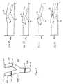
- FIG. 5shows a vessel 500 with a bifurcation 502 .
- Each branch 504 , 506 and the trunk 508is associated with an end point 510 , 512 , 514 , respectively.
- Two different cross-sectional areasare calculated by the system 100 for a plurality of locations spaced along the vessel between the end points 510 , 512 and to 514 .
- a total cross-sectional areais determined for multiple locations along the entire length of the vessel 500 .
- the total cross-sectional area for locations along the trunk 508is the cross-sectional area 518 of the trunk.
- the total cross-sectional area for locations between the bifurcation 502 and the branch end points 510 , 512is the sum of the cross-section 516 for each branch 504 , 506 .
- the cross-section 516 of one branch 504is determined for multiple locations between the bifurcation 502 and the branch end point 510 .
- the multiple locationscomprise the same locations used for calculating the total cross-sectional area.
- the cross-section of the one branch 504is determined as one of the additional branches.
- the cross-sectional areasare calculated for areas perpendicular to an angle of flow or the center axis of the vessel 500 . For example, the point along each branch center axis a same distance away from the trunk end point 514 is determined.
- the cross-sectional areas 516 usedare calculated for a plane perpendicular to the center axis of the branch 504 or 506 that includes the point. Alternatively, a plane through all or a sub-set of points in multiple branches is determined. The cross-section for each branch within that plane is calculated.
- FIGS. 6A-6Dare graphic representations of these three cross-sectional areas as a function of distance, S, along the vessel 500 where S b represents the location of the bifurcation 502 .
- the solid line, A Trepresents the total cross-sectional area.
- the dashed line, A Brepresents the cross-sectional area of the branch.
- the dot-dashed line, A T ⁇ A Brepresents the difference.
- FIG. 6Arepresents the vessel 500 without abnormalities.
- FIG. 6Bshows the vessel 500 with a constriction in the trunk 508 .
- a dip in the total cross-sectional areashows the location and extent of the constriction.
- FIG. 6Cshows the vessel 500 with a constriction in the branch 504 used for the branch cross-sectional area.
- a dip in the branch cross-sectional area and a bump in the differenceshows the location and extent of the constriction.
- FIG. 6Dshows the vessel 500 with a constriction in the branch 506 not used for the branch cross-sectional area.
- a dip in the total cross-sectional area and the difference, but not in the branch used for the cross-sectional areashows the location and extent of the constriction.
- the location and extent of the constrictionis determined without calculating the difference.
- the cross-sections of additional branchesmay also be independently determined.
- graphs as shown in FIGS. 6A-6Dare generated on the display. Other indications may be used, such as the indications discussed above. Also as discussed above, a comparison of each cross-sectional area, such as the total, different or a branch cross-sectional area, to other cross-sectional area measurements may be used. For example, an average total cross-sectional area is calculated and compared to each separate total cross-sectional area to locate an abnormality.
- the system 100determines and labels the separate branches of the carotid artery.
- the interior and exterior branches 312 and 314extend from the trunk 316 of the vessel 300 .
- the interior branch 312provides blood to the brain
- the exterior branch 314provides blood to the face. Since obstructions of flow to the brain may be more serious than obstructions to the face, the system 100 assists in focusing examination of the proper vessel and/or assists in determining the urgency or type of treatment necessary. By automated determination, radiologists may more quickly focus analysis on abnormalities, rather than vessel identification. Branch determination techniques may be applied to other vessels with bifurcations.
- the internal carotidhas few or no branches.
- the external carotidhas branches that may or may not be visible based on (a) the extent of the external branch scanned and (2) the size of the flow within the branch.
- the internal branchtends to be more medially placed and the external tends to be more laterally placed.
- the internal branchmay appear in the image to be closer to the transducer.
- two or more of the resultsare used to make the final determination.
- a weighted sumwhere the weights are determined in advance using a “training set” developed through experimentation and human selection is applied. Fuzey logic or other functions may be used.
- At least one cross-section scan that includes both the interior and exterior carotid arteryis obtained.
- FIG. 4shows one such cross-sectional scan.
- the cross-sectional scanis obtained from a set of ultrasound data representing three-dimensions or a two-dimensional scan of the region.
- a plurality of cross-section scansare obtained, such as associated with a set of data representing three-dimensions.
- the scansare associated with a same phase of the cardiac cycle.
- Contiguous vessel areas or volumesare determined as discussed above. For example, the jugular vein 402 , the interior and exterior carotid arteries 406 and 408 , and a plurality of smaller branches 404 are identified. The flow is continuous through a branch or vessel (i.e. blood in a branch is from the trunk vessel). As also discussed above, ultrasound data for one or more of the identified vessels may be removed, such as removing data associated with the jugular vein 402 .
- the exterior carotidhas a plurality of small branches 318 (FIG. 3 ), 404 (FIG. 4 ).
- the interior carotidhas few or no small branches near (e.g., immediately distal) the bifurcation 308 .
- the system 100identifies the two largest vessels after the bifurcation 308 .
- the largest vessel with the most smaller branches 318 , 404is identified as the exterior carotid 314 , 408 .
- the carotid trunk 316 , exterior carotid 314 and interior carotid 312are distinguished from smaller branches 318 by iteratively removing ultrasound data representing the surface of each vessel. This process is performed using a data set representing three-dimensions or one or more sets representing two dimensions. Smaller vessels disappear first. Once distinguished, the system 100 tracks the interconnections between vessels, such as determining the joining of axes at bifurcations as discussed above. In alternative embodiments, the user inputs a selection of two vessels likely to be the interior or exterior branches.
- the cross-sectional areais used to identify the interior and exterior carotid 312 and 314 .
- the areas defined as continuousinclude spatial locations associated with flow spaced 2 to N units away from another spatial locations associated with flow. Smaller branches are more likely to be included within the cross-sectional area being examined.
- the area of the exterior carotid 314 with the additional smaller branches includedis more likely to have an apparent larger cross-section, assuming the actual interior and exterior carotid arteries cross-sections are substantially the same size.
- the interior and exterior carotid arteries 312 and 314are labeled on the display 110 . For example, the interior carotid artery 312 is displayed with a different color, hue or brightness than the exterior carotid. As another example, a label adjacent to or with an arrow or line connecting to the appropriate artery is displayed.
- the displaymay include identification of abnormalities as discussed above. For example, a separate graph of vessel cross-sectional area is provided for and labeled for each of the interior and exterior carotid arteries 312 , 314 . Given the abnormality information and the vessel identification, the system 100 automatically provides information to assist with proper medical diagnosis.
- the ultrasound data used to identify the vessel 300comprises Doppler velocity, variance or energy estimates, B-mode data or combinations thereof. Where the system 100 is unable to identify a vessel 300 , a warning or other indication is provided to the user. Information, such as a numerical value or bar graph, indicating the confidence of the vessel and/or abnormality identification may be provided to the user.
- one or more of the techniques or systems described hereinare performed in combination with the stenosis identification techniques and systems disclosed in (Ser. No. 09/606,515, filed on Jun. 29, 2000), for a Medical Diagnostic Ultrasound System and Method for Identifying Constrictions, the disclosure of which is incorporated herein by reference.
- Constrictionsare determined as a function of volume flow measurements along a vessel. The cross-sectional area based identification of abnormalities is used to confirm accurate identification using volume flow measurements, vise versa or as a weighted combination.
- the term “vessel”includes any enclosed region or zone in a body that permits fluid flow therein.
Landscapes
- Health & Medical Sciences (AREA)
- Life Sciences & Earth Sciences (AREA)
- Engineering & Computer Science (AREA)
- Medical Informatics (AREA)
- Biophysics (AREA)
- Nuclear Medicine, Radiotherapy & Molecular Imaging (AREA)
- Pathology (AREA)
- Radiology & Medical Imaging (AREA)
- Veterinary Medicine (AREA)
- Biomedical Technology (AREA)
- Heart & Thoracic Surgery (AREA)
- Physics & Mathematics (AREA)
- Molecular Biology (AREA)
- Surgery (AREA)
- Animal Behavior & Ethology (AREA)
- General Health & Medical Sciences (AREA)
- Public Health (AREA)
- Hematology (AREA)
- Ultra Sonic Daignosis Equipment (AREA)
Abstract
Description
Claims (33)
Priority Applications (1)
| Application Number | Priority Date | Filing Date | Title |
|---|---|---|---|
| US09/607,556US6503202B1 (en) | 2000-06-29 | 2000-06-29 | Medical diagnostic ultrasound system and method for flow analysis |
Applications Claiming Priority (1)
| Application Number | Priority Date | Filing Date | Title |
|---|---|---|---|
| US09/607,556US6503202B1 (en) | 2000-06-29 | 2000-06-29 | Medical diagnostic ultrasound system and method for flow analysis |
Publications (1)
| Publication Number | Publication Date |
|---|---|
| US6503202B1true US6503202B1 (en) | 2003-01-07 |
Family
ID=24432791
Family Applications (1)
| Application Number | Title | Priority Date | Filing Date |
|---|---|---|---|
| US09/607,556Expired - LifetimeUS6503202B1 (en) | 2000-06-29 | 2000-06-29 | Medical diagnostic ultrasound system and method for flow analysis |
Country Status (1)
| Country | Link |
|---|---|
| US (1) | US6503202B1 (en) |
Cited By (99)
| Publication number | Priority date | Publication date | Assignee | Title |
|---|---|---|---|---|
| US20030171894A1 (en)* | 2002-03-08 | 2003-09-11 | Giovanni Battista Mancini A.K.A. G.B. John Mancini | Vessel evaluation methods, apparatus, computer-readable media and signals |
| US20040197015A1 (en)* | 2003-04-02 | 2004-10-07 | Siemens Medical Solutions Usa, Inc. | Border detection for medical imaging |
| US20040210403A1 (en)* | 2002-07-24 | 2004-10-21 | Benno Heigl | Processing method for a volume dataset |
| US20050010100A1 (en)* | 2003-04-30 | 2005-01-13 | Joachim Hornegger | Method and apparatus for automatic detection of anomalies in vessel structures |
| US20050033174A1 (en)* | 2003-07-10 | 2005-02-10 | Moehring Mark A. | Doppler ultrasound method and apparatus for monitoring blood flow and hemodynamics |
| US20050038343A1 (en)* | 2003-07-10 | 2005-02-17 | Alfred E. Mann Institute For Biomedical Research At The University Of Southern California | Apparatus and method for locating a bifurcation in an artery |
| US20050075568A1 (en)* | 1998-11-11 | 2005-04-07 | Moehring Mark A. | Doppler ultrasound method and apparatus for monitoring blood flow |
| US20050096528A1 (en)* | 2003-04-07 | 2005-05-05 | Sonosite, Inc. | Ultrasonic blood vessel measurement apparatus and method |
| US20050119555A1 (en)* | 2002-11-06 | 2005-06-02 | Sonosite, Inc. | Ultrasonic blood vessel measurement apparatus and method |
| US20050124898A1 (en)* | 2002-01-16 | 2005-06-09 | Ep Medsystems, Inc. | Method and apparatus for isolating a catheter interface |
| US20050203410A1 (en)* | 2004-02-27 | 2005-09-15 | Ep Medsystems, Inc. | Methods and systems for ultrasound imaging of the heart from the pericardium |
| US20050209578A1 (en)* | 2004-01-29 | 2005-09-22 | Christian Evans Edward A | Ultrasonic catheter with segmented fluid delivery |
| US20050215946A1 (en)* | 2004-01-29 | 2005-09-29 | Hansmann Douglas R | Method and apparatus for detecting vascular conditions with a catheter |
| US20050228290A1 (en)* | 2004-04-07 | 2005-10-13 | Ep Medsystems, Inc. | Steerable ultrasound catheter |
| US20050240103A1 (en)* | 2004-04-20 | 2005-10-27 | Ep Medsystems, Inc. | Method and apparatus for ultrasound imaging with autofrequency selection |
| US20050245822A1 (en)* | 2002-07-22 | 2005-11-03 | Ep Medsystems, Inc. | Method and apparatus for imaging distant anatomical structures in intra-cardiac ultrasound imaging |
| WO2005050361A3 (en)* | 2003-11-12 | 2005-12-01 | Vision Q | System and method for automatic determination of a region of interest within an image |
| US20050283075A1 (en)* | 2004-06-16 | 2005-12-22 | Siemens Medical Solutions Usa, Inc. | Three-dimensional fly-through systems and methods using ultrasound data |
| US20060106308A1 (en)* | 2001-12-14 | 2006-05-18 | Hansmann Douglas R | Blood flow reestablishment determination |
| US20060122514A1 (en)* | 2004-11-23 | 2006-06-08 | Ep Medsystems, Inc. | Method and apparatus for localizing an ultrasound catheter |
| US20060123043A1 (en)* | 2004-12-02 | 2006-06-08 | Samsung Electronics Co., Ltd. | File system path processing device and method |
| US20060173387A1 (en)* | 2004-12-10 | 2006-08-03 | Douglas Hansmann | Externally enhanced ultrasonic therapy |
| US20060184070A1 (en)* | 2004-11-12 | 2006-08-17 | Hansmann Douglas R | External ultrasonic therapy |
| WO2006057724A3 (en)* | 2004-11-29 | 2006-08-24 | Univ Leland Stanford Junior | A registration system and method for tracking lung nodules in medical images |
| US20060239528A1 (en)* | 2005-04-20 | 2006-10-26 | Siemens Aktiengesellschaft | Operating method for a computer, operating method for a medical imaging system and items corresponding thereto |
| US20060264759A1 (en)* | 2005-05-20 | 2006-11-23 | Moehring Mark A | System and method for grading microemboli monitored by a multi-gate doppler ultrasound system |
| US20070016050A1 (en)* | 2005-06-13 | 2007-01-18 | Moehring Mark A | Medical Doppler ultrasound system for locating and tracking blood flow |
| US20070083118A1 (en)* | 2002-07-22 | 2007-04-12 | Ep Medsystems, Inc. | Method and System For Estimating Cardiac Ejection Volume Using Ultrasound Spectral Doppler Image Data |
| US20070083099A1 (en)* | 2005-09-29 | 2007-04-12 | Henderson Stephen W | Path related three dimensional medical imaging |
| US20070106203A1 (en)* | 2001-12-03 | 2007-05-10 | Wilson Richard R | Catheter with multiple ultrasound radiating members |
| US20070161951A1 (en)* | 2004-01-29 | 2007-07-12 | Ekos Corporation | Treatment of vascular occlusions using elevated temperatures |
| US20070167793A1 (en)* | 2005-12-14 | 2007-07-19 | Ep Medsystems, Inc. | Method and system for enhancing spectral doppler presentation |
| US20070167794A1 (en)* | 2005-12-14 | 2007-07-19 | Ep Medsystems, Inc. | Method and system for evaluating valvular function |
| US20070167809A1 (en)* | 2002-07-22 | 2007-07-19 | Ep Medsystems, Inc. | Method and System For Estimating Cardiac Ejection Volume And Placing Pacemaker Electrodes Using Speckle Tracking |
| US20070167751A1 (en)* | 2005-12-05 | 2007-07-19 | Schilling Ronald B | Method and apparatus for vessel characterization |
| US20070232949A1 (en)* | 2006-03-31 | 2007-10-04 | Ep Medsystems, Inc. | Method For Simultaneous Bi-Atrial Mapping Of Atrial Fibrillation |
| US20070299479A1 (en)* | 2006-06-27 | 2007-12-27 | Ep Medsystems, Inc. | Method for Reversing Ventricular Dyssynchrony |
| US7314446B2 (en) | 2002-07-22 | 2008-01-01 | Ep Medsystems, Inc. | Method and apparatus for time gating of medical images |
| US20080009733A1 (en)* | 2006-06-27 | 2008-01-10 | Ep Medsystems, Inc. | Method for Evaluating Regional Ventricular Function and Incoordinate Ventricular Contraction |
| US20080021317A1 (en)* | 2006-07-24 | 2008-01-24 | Siemens Medical Solutions Usa, Inc. | Ultrasound medical imaging with robotic assistance for volume imaging |
| US20080103417A1 (en)* | 2006-10-27 | 2008-05-01 | Azita Soltani | Catheter with multiple ultrasound radiating members |
| US20080146940A1 (en)* | 2006-12-14 | 2008-06-19 | Ep Medsystems, Inc. | External and Internal Ultrasound Imaging System |
| US20080146942A1 (en)* | 2006-12-13 | 2008-06-19 | Ep Medsystems, Inc. | Catheter Position Tracking Methods Using Fluoroscopy and Rotational Sensors |
| US20080146928A1 (en)* | 2006-12-14 | 2008-06-19 | Ep Medsystems, Inc. | Method and System for Configuration of a Pacemaker and For Placement of Pacemaker Electrodes |
| US20080146943A1 (en)* | 2006-12-14 | 2008-06-19 | Ep Medsystems, Inc. | Integrated Beam Former And Isolation For An Ultrasound Probe |
| US20080194996A1 (en)* | 2003-02-21 | 2008-08-14 | Kassab Ghassan S | Device, system and method for measuring cross-sectional areas in luminal organs |
| US20080312536A1 (en)* | 2007-06-16 | 2008-12-18 | Ep Medsystems, Inc. | Oscillating Phased-Array Ultrasound Imaging Catheter System |
| US20090003675A1 (en)* | 2007-03-27 | 2009-01-01 | Siemens Corporate Research, Inc. | Bleeding Detection Using a Blanket Ultrasound Device |
| US20090024033A1 (en)* | 2007-07-17 | 2009-01-22 | Aloka Co., Ltd. | Ultrasound diagnostic apparatus |
| US20090024029A1 (en)* | 2007-07-17 | 2009-01-22 | Aloka Co., Ltd. | Ultrasound diagnostic apparatus |
| US20090306503A1 (en)* | 2008-06-06 | 2009-12-10 | Seshadri Srinivasan | Adaptive volume rendering for ultrasound color flow diagnostic imaging |
| US7648462B2 (en) | 2002-01-16 | 2010-01-19 | St. Jude Medical, Atrial Fibrillation Division, Inc. | Safety systems and methods for ensuring safe use of intra-cardiac ultrasound catheters |
| US20100160779A1 (en)* | 2006-08-11 | 2010-06-24 | Koninklijke Philips Electronics N.V. | Ultrasound system for cerebral blood flow imaging and microbubble-enhanced blood clot lysis |
| US20100160780A1 (en)* | 2006-08-11 | 2010-06-24 | Koninklijke Philips Electronics N.V. | Ultrasound System for Cerebral Blood Flow Imaging and Microbubble-Enhanced Blood Clot Lysis |
| WO2011038305A2 (en) | 2009-09-25 | 2011-03-31 | Volcano Corporation | Device and method for determining the likelihood of a patient having a clinical event or a clinically silent event based on ascertained physiological parameters |
| RU2421146C1 (en)* | 2009-12-22 | 2011-06-20 | Государственное образовательное учреждение высшего профессионального образования "БАШКИРСКИЙ ГОСУДАРСТВЕННЫЙ МЕДИЦИНСКИЙ УНИВЕРСИТЕТ ФЕДЕРАЛЬНОГО АГЕНТСТВА ПО ЗДРАВООХРАНЕНИЮ И СОЦИАЛЬНОМУ РАЗВИТИЮ" | Method of diagnosing hemodynamically significant stenosis in extracranial part of carotid arteries during mass dental examination |
| US8052607B2 (en) | 2008-04-22 | 2011-11-08 | St. Jude Medical, Atrial Fibrillation Division, Inc. | Ultrasound imaging catheter with pivoting head |
| US8057394B2 (en) | 2007-06-30 | 2011-11-15 | St. Jude Medical, Atrial Fibrillation Division, Inc. | Ultrasound image processing to render three-dimensional images from two-dimensional images |
| US20120041319A1 (en)* | 2010-08-12 | 2012-02-16 | Heartflow, Inc. | Method and system for patient-specific modeling of blood flow |
| WO2012092444A2 (en) | 2010-12-31 | 2012-07-05 | Volcano Corporation | Diagnostic and therapeutic methods, devices, and systems for multiple sclerosis, deep vein thrombosis, and pulmonary embolism patients |
| US8226629B1 (en) | 2002-04-01 | 2012-07-24 | Ekos Corporation | Ultrasonic catheter power control |
| US20130274607A1 (en)* | 2010-12-22 | 2013-10-17 | Koninklijke Philips Electronics N.V. | Automated doppler velocimetry using a low-cost transducer |
| US20140066738A1 (en)* | 2003-02-21 | 2014-03-06 | Ghassan S. Kassab | Systems, devices, and methods for mapping organ profiles |
| US20140081142A1 (en)* | 2012-04-23 | 2014-03-20 | Panasonic Corporation | Ultrasound diagnostic apparatus and control method for ultrasound diagnostic device |
| US8764700B2 (en) | 1998-06-29 | 2014-07-01 | Ekos Corporation | Sheath for use with an ultrasound element |
| EP2886058A1 (en)* | 2013-12-18 | 2015-06-24 | Samsung Medison Co., Ltd. | Apparatus and method for displaying a degree of stenosis in an ultrasound image |
| US20160078668A1 (en)* | 2014-09-11 | 2016-03-17 | Siemens Medical Solutions Usa, Inc. | Velocity volume rendering with sign-based terrmination in ultrasound |
| US20160113628A1 (en)* | 2013-05-24 | 2016-04-28 | Medyria Ag | Flow sensor arrangement and method for using a flow sensor arrangement |
| KR20170053950A (en)* | 2015-11-09 | 2017-05-17 | 삼성전자주식회사 | Probe apparatus and the controlling method thereof |
| EP3199108A1 (en)* | 2016-02-01 | 2017-08-02 | Samsung Medison Co., Ltd. | Method and apparatus for displaying ultrasound image |
| US10092742B2 (en) | 2014-09-22 | 2018-10-09 | Ekos Corporation | Catheter system |
| US10159531B2 (en) | 2012-04-05 | 2018-12-25 | C. R. Bard, Inc. | Apparatus and methods relating to intravascular positioning of distal end of catheter |
| US10172538B2 (en) | 2003-02-21 | 2019-01-08 | 3Dt Holdings, Llc | Body lumen junction localization |
| US10354050B2 (en) | 2009-03-17 | 2019-07-16 | The Board Of Trustees Of Leland Stanford Junior University | Image processing method for determining patient-specific cardiovascular information |
| US10617388B2 (en) | 2016-01-05 | 2020-04-14 | Neural Analytics, Inc. | Integrated probe structure |
| US10656025B2 (en) | 2015-06-10 | 2020-05-19 | Ekos Corporation | Ultrasound catheter |
| US10709417B2 (en) | 2016-01-05 | 2020-07-14 | Neural Analytics, Inc. | Systems and methods for detecting neurological conditions |
| WO2020188022A1 (en)* | 2019-03-19 | 2020-09-24 | Koninklijke Philips N.V. | Three dimensional volume flow quantification and measurement |
| US10806428B2 (en) | 2015-02-12 | 2020-10-20 | Foundry Innovation & Research 1, Ltd. | Implantable devices and related methods for heart failure monitoring |
| US10806352B2 (en) | 2016-11-29 | 2020-10-20 | Foundry Innovation & Research 1, Ltd. | Wireless vascular monitoring implants |
| US11000205B2 (en) | 2012-04-05 | 2021-05-11 | Bard Access Systems, Inc. | Devices and systems for navigation and positioning a central venous catheter within a patient |
| US11039813B2 (en) | 2015-08-03 | 2021-06-22 | Foundry Innovation & Research 1, Ltd. | Devices and methods for measurement of Vena Cava dimensions, pressure and oxygen saturation |
| CN113038885A (en)* | 2018-11-20 | 2021-06-25 | 皇家飞利浦有限公司 | Ultrasonic control unit |
| CN113164156A (en)* | 2018-12-04 | 2021-07-23 | 皇家飞利浦有限公司 | System and method for guided ultrasound data acquisition |
| US11090026B2 (en) | 2016-01-05 | 2021-08-17 | Novasignal Corp. | Systems and methods for determining clinical indications |
| US11107587B2 (en) | 2008-07-21 | 2021-08-31 | The Board Of Trustees Of The Leland Stanford Junior University | Method for tuning patient-specific cardiovascular simulations |
| CN113440165A (en)* | 2021-08-10 | 2021-09-28 | 上海市第六人民医院 | Wearable visual ultrasonic non-invasive monitoring equipment |
| US11207054B2 (en) | 2015-06-19 | 2021-12-28 | Novasignal Corp. | Transcranial doppler probe |
| US11206992B2 (en) | 2016-08-11 | 2021-12-28 | Foundry Innovation & Research 1, Ltd. | Wireless resonant circuit and variable inductance vascular monitoring implants and anchoring structures therefore |
| US11317875B2 (en)* | 2016-09-30 | 2022-05-03 | Siemens Healthcare Gmbh | Reconstruction of flow data |
| US11458290B2 (en) | 2011-05-11 | 2022-10-04 | Ekos Corporation | Ultrasound system |
| US11564596B2 (en) | 2016-08-11 | 2023-01-31 | Foundry Innovation & Research 1, Ltd. | Systems and methods for patient fluid management |
| US11672553B2 (en) | 2007-06-22 | 2023-06-13 | Ekos Corporation | Method and apparatus for treatment of intracranial hemorrhages |
| US11701018B2 (en) | 2016-08-11 | 2023-07-18 | Foundry Innovation & Research 1, Ltd. | Wireless resonant circuit and variable inductance vascular monitoring implants and anchoring structures therefore |
| US11759268B2 (en) | 2012-04-05 | 2023-09-19 | C. R. Bard, Inc. | Apparatus and methods relating to intravascular positioning of distal end of catheter |
| US11779238B2 (en) | 2017-05-31 | 2023-10-10 | Foundry Innovation & Research 1, Ltd. | Implantable sensors for vascular monitoring |
| US11925367B2 (en) | 2007-01-08 | 2024-03-12 | Ekos Corporation | Power parameters for ultrasonic catheter |
| US11944495B2 (en) | 2017-05-31 | 2024-04-02 | Foundry Innovation & Research 1, Ltd. | Implantable ultrasonic vascular sensor |
| US12029539B2 (en) | 2003-02-21 | 2024-07-09 | 3Dt Holdings, Llc | Systems, devices, and methods for mapping organ profiles |
Citations (9)
| Publication number | Priority date | Publication date | Assignee | Title |
|---|---|---|---|---|
| US5474073A (en) | 1994-11-22 | 1995-12-12 | Advanced Technology Laboratories, Inc. | Ultrasonic diagnostic scanning for three dimensional display |
| US5477858A (en)* | 1986-07-30 | 1995-12-26 | Siemens Medical Systems, Inc. | Ultrasound blood flow/tissue imaging system |
| US5623930A (en) | 1995-05-02 | 1997-04-29 | Acuson Corporation | Ultrasound system for flow measurement |
| US5771896A (en) | 1993-05-28 | 1998-06-30 | Acuson Corporation | Compact rotationally steerable ultrasound transducer |
| US5876345A (en) | 1997-02-27 | 1999-03-02 | Acuson Corporation | Ultrasonic catheter, system and method for two dimensional imaging or three-dimensional reconstruction |
| US5928151A (en) | 1997-08-22 | 1999-07-27 | Acuson Corporation | Ultrasonic system and method for harmonic imaging in three dimensions |
| US5967987A (en) | 1997-12-18 | 1999-10-19 | Acuson Corporation | Ultrasonic system and method for measurement of fluid flow |
| US6014473A (en) | 1996-02-29 | 2000-01-11 | Acuson Corporation | Multiple ultrasound image registration system, method and transducer |
| US6045508A (en) | 1997-02-27 | 2000-04-04 | Acuson Corporation | Ultrasonic probe, system and method for two-dimensional imaging or three-dimensional reconstruction |
- 2000
- 2000-06-29USUS09/607,556patent/US6503202B1/ennot_activeExpired - Lifetime
Patent Citations (9)
| Publication number | Priority date | Publication date | Assignee | Title |
|---|---|---|---|---|
| US5477858A (en)* | 1986-07-30 | 1995-12-26 | Siemens Medical Systems, Inc. | Ultrasound blood flow/tissue imaging system |
| US5771896A (en) | 1993-05-28 | 1998-06-30 | Acuson Corporation | Compact rotationally steerable ultrasound transducer |
| US5474073A (en) | 1994-11-22 | 1995-12-12 | Advanced Technology Laboratories, Inc. | Ultrasonic diagnostic scanning for three dimensional display |
| US5623930A (en) | 1995-05-02 | 1997-04-29 | Acuson Corporation | Ultrasound system for flow measurement |
| US6014473A (en) | 1996-02-29 | 2000-01-11 | Acuson Corporation | Multiple ultrasound image registration system, method and transducer |
| US5876345A (en) | 1997-02-27 | 1999-03-02 | Acuson Corporation | Ultrasonic catheter, system and method for two dimensional imaging or three-dimensional reconstruction |
| US6045508A (en) | 1997-02-27 | 2000-04-04 | Acuson Corporation | Ultrasonic probe, system and method for two-dimensional imaging or three-dimensional reconstruction |
| US5928151A (en) | 1997-08-22 | 1999-07-27 | Acuson Corporation | Ultrasonic system and method for harmonic imaging in three dimensions |
| US5967987A (en) | 1997-12-18 | 1999-10-19 | Acuson Corporation | Ultrasonic system and method for measurement of fluid flow |
Non-Patent Citations (5)
| Title |
|---|
| Carlo Palombo, MD; Ultrafast Three-Dimensional Ultrasound-Application to Carotid Artery Imaging; pp. 1631-1637. |
| Carlo Palombo, MD; Ultrafast Three-Dimensional Ultrasound—Application to Carotid Artery Imaging; pp. 1631-1637. |
| Paik et al., "Automated Flight Path Planning for Virtual Ends" Medical Physics, May, 1998; 25(5): 629-637. |
| Scott Unbaugh; "Computer Vision and Image Processing-A Practical Approach . . .", Prentice Hall PTR, Upper Saddle River, NJ 07458. |
| Scott Unbaugh; "Computer Vision and Image Processing—A Practical Approach . . .", Prentice Hall PTR, Upper Saddle River, NJ 07458. |
Cited By (249)
| Publication number | Priority date | Publication date | Assignee | Title |
|---|---|---|---|---|
| US8764700B2 (en) | 1998-06-29 | 2014-07-01 | Ekos Corporation | Sheath for use with an ultrasound element |
| US7537568B2 (en) | 1998-11-11 | 2009-05-26 | Spentech, Inc. | Doppler ultrasound method and apparatus for monitoring blood flow |
| US20050075568A1 (en)* | 1998-11-11 | 2005-04-07 | Moehring Mark A. | Doppler ultrasound method and apparatus for monitoring blood flow |
| US7727178B2 (en) | 2001-12-03 | 2010-06-01 | Ekos Corporation | Catheter with multiple ultrasound radiating members |
| US8167831B2 (en) | 2001-12-03 | 2012-05-01 | Ekos Corporation | Catheter with multiple ultrasound radiating members |
| US10926074B2 (en) | 2001-12-03 | 2021-02-23 | Ekos Corporation | Catheter with multiple ultrasound radiating members |
| US7828762B2 (en) | 2001-12-03 | 2010-11-09 | Ekos Corporation | Catheter with multiple ultrasound radiating members |
| US9415242B2 (en) | 2001-12-03 | 2016-08-16 | Ekos Corporation | Catheter with multiple ultrasound radiating members |
| US20070106203A1 (en)* | 2001-12-03 | 2007-05-10 | Wilson Richard R | Catheter with multiple ultrasound radiating members |
| US10080878B2 (en) | 2001-12-03 | 2018-09-25 | Ekos Corporation | Catheter with multiple ultrasound radiating members |
| US20070112296A1 (en)* | 2001-12-03 | 2007-05-17 | Wilson Richard R | Catheter with multiple ultrasound radiating members |
| US8696612B2 (en) | 2001-12-03 | 2014-04-15 | Ekos Corporation | Catheter with multiple ultrasound radiating members |
| US20060106308A1 (en)* | 2001-12-14 | 2006-05-18 | Hansmann Douglas R | Blood flow reestablishment determination |
| US7648462B2 (en) | 2002-01-16 | 2010-01-19 | St. Jude Medical, Atrial Fibrillation Division, Inc. | Safety systems and methods for ensuring safe use of intra-cardiac ultrasound catheters |
| US20050124898A1 (en)* | 2002-01-16 | 2005-06-09 | Ep Medsystems, Inc. | Method and apparatus for isolating a catheter interface |
| US7165010B2 (en)* | 2002-03-08 | 2007-01-16 | The University Of British Columbia | Vessel evaluation methods, apparatus, computer-readable media and signals |
| US20030171894A1 (en)* | 2002-03-08 | 2003-09-11 | Giovanni Battista Mancini A.K.A. G.B. John Mancini | Vessel evaluation methods, apparatus, computer-readable media and signals |
| US8852166B1 (en) | 2002-04-01 | 2014-10-07 | Ekos Corporation | Ultrasonic catheter power control |
| US9943675B1 (en) | 2002-04-01 | 2018-04-17 | Ekos Corporation | Ultrasonic catheter power control |
| US8226629B1 (en) | 2002-04-01 | 2012-07-24 | Ekos Corporation | Ultrasonic catheter power control |
| US7314446B2 (en) | 2002-07-22 | 2008-01-01 | Ep Medsystems, Inc. | Method and apparatus for time gating of medical images |
| US20070167809A1 (en)* | 2002-07-22 | 2007-07-19 | Ep Medsystems, Inc. | Method and System For Estimating Cardiac Ejection Volume And Placing Pacemaker Electrodes Using Speckle Tracking |
| US20070083118A1 (en)* | 2002-07-22 | 2007-04-12 | Ep Medsystems, Inc. | Method and System For Estimating Cardiac Ejection Volume Using Ultrasound Spectral Doppler Image Data |
| US20050245822A1 (en)* | 2002-07-22 | 2005-11-03 | Ep Medsystems, Inc. | Method and apparatus for imaging distant anatomical structures in intra-cardiac ultrasound imaging |
| US6912471B2 (en)* | 2002-07-24 | 2005-06-28 | Siemens Aktiengesellschaft | Processing method for a volume dataset |
| US20040210403A1 (en)* | 2002-07-24 | 2004-10-21 | Benno Heigl | Processing method for a volume dataset |
| US20050119555A1 (en)* | 2002-11-06 | 2005-06-02 | Sonosite, Inc. | Ultrasonic blood vessel measurement apparatus and method |
| US8771191B2 (en)* | 2002-11-06 | 2014-07-08 | Sonosite, Inc. | Ultrasonic blood vessel measurement apparatus and method |
| US10172538B2 (en) | 2003-02-21 | 2019-01-08 | 3Dt Holdings, Llc | Body lumen junction localization |
| US10413211B2 (en) | 2003-02-21 | 2019-09-17 | 3Dt Holdings, Llc | Systems, devices, and methods for mapping organ profiles |
| US12029539B2 (en) | 2003-02-21 | 2024-07-09 | 3Dt Holdings, Llc | Systems, devices, and methods for mapping organ profiles |
| US11510589B2 (en) | 2003-02-21 | 2022-11-29 | 3Dt Holdings, Llc | Body lumen junction localization |
| US11490829B2 (en)* | 2003-02-21 | 2022-11-08 | 3Dt Holdings, Llc | Systems, devices, and methods for mapping organ profiles |
| US8078274B2 (en)* | 2003-02-21 | 2011-12-13 | Dtherapeutics, Llc | Device, system and method for measuring cross-sectional areas in luminal organs |
| US10524685B2 (en) | 2003-02-21 | 2020-01-07 | 3Dt Holdings, Llc | Methods for generating luminal organ profiles using impedance |
| US20120172746A1 (en)* | 2003-02-21 | 2012-07-05 | Kassab Ghassan S | Methods to Generate Luminal Organ Profiles Using Impedance |
| US20080194996A1 (en)* | 2003-02-21 | 2008-08-14 | Kassab Ghassan S | Device, system and method for measuring cross-sectional areas in luminal organs |
| US20140066738A1 (en)* | 2003-02-21 | 2014-03-06 | Ghassan S. Kassab | Systems, devices, and methods for mapping organ profiles |
| US9066708B2 (en)* | 2003-02-21 | 2015-06-30 | 3Dt Holdings, Llc | Methods to generate luminal organ profiles using impedance |
| US9445743B2 (en) | 2003-02-21 | 2016-09-20 | 3Dt Holdings, Llc | Methods for generating luminal organ profiles using impedance |
| US20040197015A1 (en)* | 2003-04-02 | 2004-10-07 | Siemens Medical Solutions Usa, Inc. | Border detection for medical imaging |
| US7022073B2 (en) | 2003-04-02 | 2006-04-04 | Siemens Medical Solutions Usa, Inc. | Border detection for medical imaging |
| US20050096528A1 (en)* | 2003-04-07 | 2005-05-05 | Sonosite, Inc. | Ultrasonic blood vessel measurement apparatus and method |
| US7727153B2 (en) | 2003-04-07 | 2010-06-01 | Sonosite, Inc. | Ultrasonic blood vessel measurement apparatus and method |
| US7546154B2 (en)* | 2003-04-30 | 2009-06-09 | Siemens Aktiengesellschaft | Method and apparatus for automatic detection of anomalies in vessel structures |
| US20050010100A1 (en)* | 2003-04-30 | 2005-01-13 | Joachim Hornegger | Method and apparatus for automatic detection of anomalies in vessel structures |
| US7128713B2 (en) | 2003-07-10 | 2006-10-31 | Spentech, Inc. | Doppler ultrasound method and apparatus for monitoring blood flow and hemodynamics |
| US20050033174A1 (en)* | 2003-07-10 | 2005-02-10 | Moehring Mark A. | Doppler ultrasound method and apparatus for monitoring blood flow and hemodynamics |
| US20050038343A1 (en)* | 2003-07-10 | 2005-02-17 | Alfred E. Mann Institute For Biomedical Research At The University Of Southern California | Apparatus and method for locating a bifurcation in an artery |
| US7090640B2 (en)* | 2003-11-12 | 2006-08-15 | Q-Vision | System and method for automatic determination of a region of interest within an image |
| WO2005050361A3 (en)* | 2003-11-12 | 2005-12-01 | Vision Q | System and method for automatic determination of a region of interest within an image |
| US20060056672A1 (en)* | 2003-11-12 | 2006-03-16 | Q-Vision, A California Corporation | System and method for automatic determination of a Region Of Interest within an image |
| US20050215946A1 (en)* | 2004-01-29 | 2005-09-29 | Hansmann Douglas R | Method and apparatus for detecting vascular conditions with a catheter |
| US20070161951A1 (en)* | 2004-01-29 | 2007-07-12 | Ekos Corporation | Treatment of vascular occlusions using elevated temperatures |
| US20050209578A1 (en)* | 2004-01-29 | 2005-09-22 | Christian Evans Edward A | Ultrasonic catheter with segmented fluid delivery |
| US9107590B2 (en) | 2004-01-29 | 2015-08-18 | Ekos Corporation | Method and apparatus for detecting vascular conditions with a catheter |
| US20050203410A1 (en)* | 2004-02-27 | 2005-09-15 | Ep Medsystems, Inc. | Methods and systems for ultrasound imaging of the heart from the pericardium |
| US7507205B2 (en) | 2004-04-07 | 2009-03-24 | St. Jude Medical, Atrial Fibrillation Division, Inc. | Steerable ultrasound catheter |
| US20050228290A1 (en)* | 2004-04-07 | 2005-10-13 | Ep Medsystems, Inc. | Steerable ultrasound catheter |
| US7654958B2 (en) | 2004-04-20 | 2010-02-02 | St. Jude Medical, Atrial Fibrillation Division, Inc. | Method and apparatus for ultrasound imaging with autofrequency selection |
| US20050240103A1 (en)* | 2004-04-20 | 2005-10-27 | Ep Medsystems, Inc. | Method and apparatus for ultrasound imaging with autofrequency selection |
| US8021300B2 (en)* | 2004-06-16 | 2011-09-20 | Siemens Medical Solutions Usa, Inc. | Three-dimensional fly-through systems and methods using ultrasound data |
| US20050283075A1 (en)* | 2004-06-16 | 2005-12-22 | Siemens Medical Solutions Usa, Inc. | Three-dimensional fly-through systems and methods using ultrasound data |
| US20060184070A1 (en)* | 2004-11-12 | 2006-08-17 | Hansmann Douglas R | External ultrasonic therapy |
| US20060122514A1 (en)* | 2004-11-23 | 2006-06-08 | Ep Medsystems, Inc. | Method and apparatus for localizing an ultrasound catheter |
| US10639004B2 (en) | 2004-11-23 | 2020-05-05 | St. Jude Medical, Atrial Fibrillation Division, Inc. | Method and apparatus for localizing an ultrasound catheter |
| US7713210B2 (en) | 2004-11-23 | 2010-05-11 | St. Jude Medical, Atrial Fibrillation Division, Inc. | Method and apparatus for localizing an ultrasound catheter |
| US7657073B2 (en)* | 2004-11-29 | 2010-02-02 | The Board Of Trustees Of The Leland Stanford Junior University | Registration system and method for tracking lung nodules in medical images |
| US20080212852A1 (en)* | 2004-11-29 | 2008-09-04 | Shaohua Sun | Registration System and Method For Tracking Lung Nodules In Medical Images |
| WO2006057724A3 (en)* | 2004-11-29 | 2006-08-24 | Univ Leland Stanford Junior | A registration system and method for tracking lung nodules in medical images |
| US20060123043A1 (en)* | 2004-12-02 | 2006-06-08 | Samsung Electronics Co., Ltd. | File system path processing device and method |
| US20060173387A1 (en)* | 2004-12-10 | 2006-08-03 | Douglas Hansmann | Externally enhanced ultrasonic therapy |
| DE102005018327A1 (en)* | 2005-04-20 | 2006-10-26 | Siemens Ag | Operating method for a computer, operating method for an imaging medical-technical system and objects corresponding thereto |
| US20060239528A1 (en)* | 2005-04-20 | 2006-10-26 | Siemens Aktiengesellschaft | Operating method for a computer, operating method for a medical imaging system and items corresponding thereto |
| US20060264759A1 (en)* | 2005-05-20 | 2006-11-23 | Moehring Mark A | System and method for grading microemboli monitored by a multi-gate doppler ultrasound system |
| US7771358B2 (en) | 2005-05-20 | 2010-08-10 | Spentech, Inc. | System and method for grading microemboli monitored by a multi-gate doppler ultrasound system |
| US8162837B2 (en) | 2005-06-13 | 2012-04-24 | Spentech, Inc. | Medical doppler ultrasound system for locating and tracking blood flow |
| US20070016050A1 (en)* | 2005-06-13 | 2007-01-18 | Moehring Mark A | Medical Doppler ultrasound system for locating and tracking blood flow |
| US20070083099A1 (en)* | 2005-09-29 | 2007-04-12 | Henderson Stephen W | Path related three dimensional medical imaging |
| US20070167751A1 (en)* | 2005-12-05 | 2007-07-19 | Schilling Ronald B | Method and apparatus for vessel characterization |
| US20070167793A1 (en)* | 2005-12-14 | 2007-07-19 | Ep Medsystems, Inc. | Method and system for enhancing spectral doppler presentation |
| US20070167794A1 (en)* | 2005-12-14 | 2007-07-19 | Ep Medsystems, Inc. | Method and system for evaluating valvular function |
| US8070684B2 (en) | 2005-12-14 | 2011-12-06 | St. Jude Medical, Atrial Fibrillation Division, Inc. | Method and system for evaluating valvular function |
| US20070232949A1 (en)* | 2006-03-31 | 2007-10-04 | Ep Medsystems, Inc. | Method For Simultaneous Bi-Atrial Mapping Of Atrial Fibrillation |
| US20070299479A1 (en)* | 2006-06-27 | 2007-12-27 | Ep Medsystems, Inc. | Method for Reversing Ventricular Dyssynchrony |
| US20080009733A1 (en)* | 2006-06-27 | 2008-01-10 | Ep Medsystems, Inc. | Method for Evaluating Regional Ventricular Function and Incoordinate Ventricular Contraction |
| US20080021317A1 (en)* | 2006-07-24 | 2008-01-24 | Siemens Medical Solutions Usa, Inc. | Ultrasound medical imaging with robotic assistance for volume imaging |
| US9630028B2 (en)* | 2006-08-11 | 2017-04-25 | Koninklijke Philips N.V. | Ultrasound system for cerebral blood flow imaging and microbubble-enhanced blood clot lysis |
| US20100160779A1 (en)* | 2006-08-11 | 2010-06-24 | Koninklijke Philips Electronics N.V. | Ultrasound system for cerebral blood flow imaging and microbubble-enhanced blood clot lysis |
| US20100160780A1 (en)* | 2006-08-11 | 2010-06-24 | Koninklijke Philips Electronics N.V. | Ultrasound System for Cerebral Blood Flow Imaging and Microbubble-Enhanced Blood Clot Lysis |
| US10363012B2 (en) | 2006-08-11 | 2019-07-30 | Koninklijke Philips N.V. | Ultrasound system for cerebral blood flow imaging and microbubble-enhanced blood clot lysis |
| US8211023B2 (en)* | 2006-08-11 | 2012-07-03 | Koninklijke Philips Electronics N.V. | Ultrasound system for cerebral blood flow monitoring |
| US20080103417A1 (en)* | 2006-10-27 | 2008-05-01 | Azita Soltani | Catheter with multiple ultrasound radiating members |
| US8192363B2 (en) | 2006-10-27 | 2012-06-05 | Ekos Corporation | Catheter with multiple ultrasound radiating members |
| US20080146942A1 (en)* | 2006-12-13 | 2008-06-19 | Ep Medsystems, Inc. | Catheter Position Tracking Methods Using Fluoroscopy and Rotational Sensors |
| US8187190B2 (en) | 2006-12-14 | 2012-05-29 | St. Jude Medical, Atrial Fibrillation Division, Inc. | Method and system for configuration of a pacemaker and for placement of pacemaker electrodes |
| US20080146943A1 (en)* | 2006-12-14 | 2008-06-19 | Ep Medsystems, Inc. | Integrated Beam Former And Isolation For An Ultrasound Probe |
| US20080146928A1 (en)* | 2006-12-14 | 2008-06-19 | Ep Medsystems, Inc. | Method and System for Configuration of a Pacemaker and For Placement of Pacemaker Electrodes |
| US20080146940A1 (en)* | 2006-12-14 | 2008-06-19 | Ep Medsystems, Inc. | External and Internal Ultrasound Imaging System |
| US11925367B2 (en) | 2007-01-08 | 2024-03-12 | Ekos Corporation | Power parameters for ultrasonic catheter |
| US20090003675A1 (en)* | 2007-03-27 | 2009-01-01 | Siemens Corporate Research, Inc. | Bleeding Detection Using a Blanket Ultrasound Device |
| US7920731B2 (en)* | 2007-03-27 | 2011-04-05 | Siemens Medical Solutions Usa, Inc. | Bleeding detection using a blanket ultrasound device |
| US20080312536A1 (en)* | 2007-06-16 | 2008-12-18 | Ep Medsystems, Inc. | Oscillating Phased-Array Ultrasound Imaging Catheter System |
| US8317711B2 (en) | 2007-06-16 | 2012-11-27 | St. Jude Medical, Atrial Fibrillation Division, Inc. | Oscillating phased-array ultrasound imaging catheter system |
| US11672553B2 (en) | 2007-06-22 | 2023-06-13 | Ekos Corporation | Method and apparatus for treatment of intracranial hemorrhages |
| US8057394B2 (en) | 2007-06-30 | 2011-11-15 | St. Jude Medical, Atrial Fibrillation Division, Inc. | Ultrasound image processing to render three-dimensional images from two-dimensional images |
| US8622915B2 (en) | 2007-06-30 | 2014-01-07 | St. Jude Medical, Atrial Fibrillation Division, Inc. | Ultrasound image processing to render three-dimensional images from two-dimensional images |
| US9697634B2 (en) | 2007-06-30 | 2017-07-04 | St. Jude Medical, Atrial Fibrillation Division, Inc. | Ultrasound image processing to render three-dimensional images from two-dimensional images |
| US11217000B2 (en) | 2007-06-30 | 2022-01-04 | St. Jude Medical, Atrial Fibrillation Division, Inc. | Ultrasound image processing to render three-dimensional images from two-dimensional images |
| CN101347341B (en)* | 2007-07-17 | 2012-07-18 | 日立阿洛卡医疗株式会社 | Ultrasound diagnostic apparatus |
| US20090024029A1 (en)* | 2007-07-17 | 2009-01-22 | Aloka Co., Ltd. | Ultrasound diagnostic apparatus |
| EP2016905A3 (en)* | 2007-07-17 | 2010-10-06 | Aloka Co., Ltd. | Ultrasound diagnostic apparatus |
| US20090024033A1 (en)* | 2007-07-17 | 2009-01-22 | Aloka Co., Ltd. | Ultrasound diagnostic apparatus |
| EP2016906A3 (en)* | 2007-07-17 | 2011-05-25 | Aloka Co., Ltd. | Ultrasound diagnostic apparatus |
| US8202220B2 (en) | 2007-07-17 | 2012-06-19 | Hitachi Aloka Medical, Ltd. | Ultrasound diagnostic apparatus |
| US9039620B2 (en) | 2007-07-17 | 2015-05-26 | Hitachi Aloka Medical, Ltd. | Ultrasound diagnostic apparatus |
| US8052607B2 (en) | 2008-04-22 | 2011-11-08 | St. Jude Medical, Atrial Fibrillation Division, Inc. | Ultrasound imaging catheter with pivoting head |
| US20090306503A1 (en)* | 2008-06-06 | 2009-12-10 | Seshadri Srinivasan | Adaptive volume rendering for ultrasound color flow diagnostic imaging |
| US8425422B2 (en) | 2008-06-06 | 2013-04-23 | Siemens Medical Solutions Usa, Inc. | Adaptive volume rendering for ultrasound color flow diagnostic imaging |
| US11107587B2 (en) | 2008-07-21 | 2021-08-31 | The Board Of Trustees Of The Leland Stanford Junior University | Method for tuning patient-specific cardiovascular simulations |
| US12176094B2 (en) | 2009-03-17 | 2024-12-24 | The Board Of Trustees Of Leland Stanford Junior University | Systems and methods for processing electronic images |
| US10354050B2 (en) | 2009-03-17 | 2019-07-16 | The Board Of Trustees Of Leland Stanford Junior University | Image processing method for determining patient-specific cardiovascular information |
| WO2011038305A2 (en) | 2009-09-25 | 2011-03-31 | Volcano Corporation | Device and method for determining the likelihood of a patient having a clinical event or a clinically silent event based on ascertained physiological parameters |
| EP2480129A4 (en)* | 2009-09-25 | 2016-03-23 | Volcano Corp | DEVICE AND METHOD FOR DETERMINING THE RISK OF A PATIENT TO SUBMIT A CLINICAL EVENT OR SILENT CLINICAL EVENT BASED ON SELECTED PHYSIOLOGICAL PARAMETERS |
| RU2421146C1 (en)* | 2009-12-22 | 2011-06-20 | Государственное образовательное учреждение высшего профессионального образования "БАШКИРСКИЙ ГОСУДАРСТВЕННЫЙ МЕДИЦИНСКИЙ УНИВЕРСИТЕТ ФЕДЕРАЛЬНОГО АГЕНТСТВА ПО ЗДРАВООХРАНЕНИЮ И СОЦИАЛЬНОМУ РАЗВИТИЮ" | Method of diagnosing hemodynamically significant stenosis in extracranial part of carotid arteries during mass dental examination |
| US9081882B2 (en) | 2010-08-12 | 2015-07-14 | HeartFlow, Inc | Method and system for patient-specific modeling of blood flow |
| US8386188B2 (en) | 2010-08-12 | 2013-02-26 | Heartflow, Inc. | Method and system for patient-specific modeling of blood flow |
| US9149197B2 (en) | 2010-08-12 | 2015-10-06 | Heartflow, Inc. | Method and system for patient-specific modeling of blood flow |
| US9167974B2 (en) | 2010-08-12 | 2015-10-27 | Heartflow, Inc. | Method and system for patient-specific modeling of blood flow |
| US9226672B2 (en) | 2010-08-12 | 2016-01-05 | Heartflow, Inc. | Method and system for patient-specific modeling of blood flow |
| US9235679B2 (en) | 2010-08-12 | 2016-01-12 | Heartflow, Inc. | Method and system for patient-specific modeling of blood flow |
| US9268902B2 (en) | 2010-08-12 | 2016-02-23 | Heartflow, Inc. | Method and system for patient-specific modeling of blood flow |
| US9271657B2 (en) | 2010-08-12 | 2016-03-01 | Heartflow, Inc. | Method and system for patient-specific modeling of blood flow |
| US12357387B2 (en) | 2010-08-12 | 2025-07-15 | Heartflow, Inc. | Method and system for image processing to determine blood flow |
| US9078564B2 (en) | 2010-08-12 | 2015-07-14 | Heartflow, Inc. | Method and system for patient-specific modeling of blood flow |
| US20120041319A1 (en)* | 2010-08-12 | 2012-02-16 | Heartflow, Inc. | Method and system for patient-specific modeling of blood flow |
| US20120150516A1 (en)* | 2010-08-12 | 2012-06-14 | Heartflow, Inc. | Method and system for patient-specific modeling of blood flow |
| US12029494B2 (en) | 2010-08-12 | 2024-07-09 | Heartflow, Inc. | Method and system for image processing to determine blood flow |
| US12016635B2 (en) | 2010-08-12 | 2024-06-25 | Heartflow, Inc. | Method and system for image processing to determine blood flow |
| US9449147B2 (en) | 2010-08-12 | 2016-09-20 | Heartflow, Inc. | Method and system for patient-specific modeling of blood flow |
| US8812245B2 (en) | 2010-08-12 | 2014-08-19 | Heartflow, Inc. | Method and system for patient-specific modeling of blood flow |
| US11793575B2 (en) | 2010-08-12 | 2023-10-24 | Heartflow, Inc. | Method and system for image processing to determine blood flow |
| US8311750B2 (en) | 2010-08-12 | 2012-11-13 | Heartflow, Inc. | Method and system for patient-specific modeling of blood flow |
| US9585723B2 (en) | 2010-08-12 | 2017-03-07 | Heartflow, Inc. | Method and system for image processing to determine patient-specific blood flow characteristics |
| US8812246B2 (en) | 2010-08-12 | 2014-08-19 | Heartflow, Inc. | Method and system for patient-specific modeling of blood flow |
| US11583340B2 (en) | 2010-08-12 | 2023-02-21 | Heartflow, Inc. | Method and system for image processing to determine blood flow |
| US8311747B2 (en) | 2010-08-12 | 2012-11-13 | Heartflow, Inc. | Method and system for patient-specific modeling of blood flow |
| US9697330B2 (en) | 2010-08-12 | 2017-07-04 | Heartflow, Inc. | Method and system for image processing to determine patient-specific blood flow characteristics |
| US9706925B2 (en) | 2010-08-12 | 2017-07-18 | Heartflow, Inc. | Method and system for image processing to determine patient-specific blood flow characteristics |
| US8315812B2 (en) | 2010-08-12 | 2012-11-20 | Heartflow, Inc. | Method and system for patient-specific modeling of blood flow |
| US11298187B2 (en) | 2010-08-12 | 2022-04-12 | Heartflow, Inc. | Method and system for image processing to determine patient-specific blood flow characteristics |
| US9743835B2 (en) | 2010-08-12 | 2017-08-29 | Heartflow, Inc. | Method and system for image processing to determine patient-specific blood flow characteristics |
| US8315813B2 (en) | 2010-08-12 | 2012-11-20 | Heartflow, Inc. | Method and system for patient-specific modeling of blood flow |
| US9801689B2 (en) | 2010-08-12 | 2017-10-31 | Heartflow, Inc. | Method and system for patient-specific modeling of blood flow |
| US9839484B2 (en) | 2010-08-12 | 2017-12-12 | Heartflow, Inc. | Method and system for image processing and patient-specific modeling of blood flow |
| US9855105B2 (en) | 2010-08-12 | 2018-01-02 | Heartflow, Inc. | Method and system for image processing to determine patient-specific blood flow characteristics |
| US11154361B2 (en) | 2010-08-12 | 2021-10-26 | Heartflow, Inc. | Method and system for image processing to determine blood flow |
| US9861284B2 (en) | 2010-08-12 | 2018-01-09 | Heartflow, Inc. | Method and system for image processing to determine patient-specific blood flow characteristics |
| US9888971B2 (en) | 2010-08-12 | 2018-02-13 | Heartflow, Inc. | Method and system for image processing to determine patient-specific blood flow characteristics |
| US11135012B2 (en) | 2010-08-12 | 2021-10-05 | Heartflow, Inc. | Method and system for image processing to determine patient-specific blood flow characteristics |
| US10052158B2 (en) | 2010-08-12 | 2018-08-21 | Heartflow, Inc. | Method and system for image processing to determine patient-specific blood flow characteristics |
| US10080613B2 (en) | 2010-08-12 | 2018-09-25 | Heartflow, Inc. | Systems and methods for determining and visualizing perfusion of myocardial muscle |
| US10080614B2 (en) | 2010-08-12 | 2018-09-25 | Heartflow, Inc. | Method and system for image processing to determine patient-specific blood flow characteristics |
| US8630812B2 (en) | 2010-08-12 | 2014-01-14 | Heartflow, Inc. | Method and system for patient-specific modeling of blood flow |
| US10092360B2 (en) | 2010-08-12 | 2018-10-09 | Heartflow, Inc. | Method and system for image processing and patient-specific modeling of blood flow |
| US11116575B2 (en) | 2010-08-12 | 2021-09-14 | Heartflow, Inc. | Method and system for image processing to determine blood flow |
| US8315814B2 (en) | 2010-08-12 | 2012-11-20 | Heartflow, Inc. | Method and system for patient-specific modeling of blood flow |
| US10149723B2 (en) | 2010-08-12 | 2018-12-11 | Heartflow, Inc. | Method and system for image processing and patient-specific modeling of blood flow |
| US10154883B2 (en) | 2010-08-12 | 2018-12-18 | Heartflow, Inc. | Method and system for image processing and patient-specific modeling of blood flow |
| US10159529B2 (en) | 2010-08-12 | 2018-12-25 | Heartflow, Inc. | Method and system for patient-specific modeling of blood flow |
| US11090118B2 (en) | 2010-08-12 | 2021-08-17 | Heartflow, Inc. | Method and system for image processing and patient-specific modeling of blood flow |
| US10166077B2 (en) | 2010-08-12 | 2019-01-01 | Heartflow, Inc. | Method and system for image processing to determine patient-specific blood flow characteristics |
| US8606530B2 (en) | 2010-08-12 | 2013-12-10 | Heartflow, Inc. | Method and system for patient-specific modeling of blood flow |
| US10179030B2 (en) | 2010-08-12 | 2019-01-15 | Heartflow, Inc. | Method and system for patient-specific modeling of blood flow |
| US10321958B2 (en) | 2010-08-12 | 2019-06-18 | Heartflow, Inc. | Method and system for image processing to determine patient-specific blood flow characteristics |
| US10327847B2 (en) | 2010-08-12 | 2019-06-25 | Heartflow, Inc. | Method and system for patient-specific modeling of blood flow |
| US8594950B2 (en) | 2010-08-12 | 2013-11-26 | Heartflow, Inc. | Method and system for patient-specific modeling of blood flow |
| US11083524B2 (en) | 2010-08-12 | 2021-08-10 | Heartflow, Inc. | Method and system for patient-specific modeling of blood flow |
| US10376317B2 (en) | 2010-08-12 | 2019-08-13 | Heartflow, Inc. | Method and system for image processing and patient-specific modeling of blood flow |
| US8523779B2 (en)* | 2010-08-12 | 2013-09-03 | Heartflow, Inc. | Method and system for patient-specific modeling of blood flow |
| US10441361B2 (en) | 2010-08-12 | 2019-10-15 | Heartflow, Inc. | Method and system for image processing and patient-specific modeling of blood flow |
| US10478252B2 (en) | 2010-08-12 | 2019-11-19 | Heartflow, Inc. | Method and system for patient-specific modeling of blood flow |
| US10492866B2 (en) | 2010-08-12 | 2019-12-03 | Heartflow, Inc. | Method and system for image processing to determine blood flow |
| US11033332B2 (en) | 2010-08-12 | 2021-06-15 | Heartflow, Inc. | Method and system for image processing to determine blood flow |
| US8496594B2 (en)* | 2010-08-12 | 2013-07-30 | Heartflow, Inc. | Method and system for patient-specific modeling of blood flow |
| US10531923B2 (en) | 2010-08-12 | 2020-01-14 | Heartflow, Inc. | Method and system for image processing to determine blood flow |
| US8321150B2 (en) | 2010-08-12 | 2012-11-27 | Heartflow, Inc. | Method and system for patient-specific modeling of blood flow |
| US9152757B2 (en) | 2010-08-12 | 2015-10-06 | Heartflow, Inc. | Method and system for patient-specific modeling of blood flow |
| US10702340B2 (en) | 2010-08-12 | 2020-07-07 | Heartflow, Inc. | Image processing and patient-specific modeling of blood flow |
| US10682180B2 (en) | 2010-08-12 | 2020-06-16 | Heartflow, Inc. | Method and system for patient-specific modeling of blood flow |
| US10702339B2 (en) | 2010-08-12 | 2020-07-07 | Heartflow, Inc. | Method and system for patient-specific modeling of blood flow |
| US9351708B2 (en)* | 2010-12-22 | 2016-05-31 | Koninklijke Philips N.V. | Automated doppler velocimetry using a low-cost transducer |
| RU2607510C2 (en)* | 2010-12-22 | 2017-01-10 | Конинклейке Филипс Электроникс Н.В. | Automated measurement of doppler velocity using cheap converter |
| US20130274607A1 (en)* | 2010-12-22 | 2013-10-17 | Koninklijke Philips Electronics N.V. | Automated doppler velocimetry using a low-cost transducer |
| EP2654572B1 (en)* | 2010-12-22 | 2017-09-13 | Koninklijke Philips N.V. | Automated doppler velocimetry using a low-cost transducer |
| WO2012092444A2 (en) | 2010-12-31 | 2012-07-05 | Volcano Corporation | Diagnostic and therapeutic methods, devices, and systems for multiple sclerosis, deep vein thrombosis, and pulmonary embolism patients |
| US9498183B2 (en) | 2010-12-31 | 2016-11-22 | Volcano Corporation | Pulmonary embolism therapeutic methods using therapeutic delivery devices and systems |
| EP2658451A4 (en)* | 2010-12-31 | 2014-07-09 | Volcano Corp | DIAGNOSTIC AND THERAPEUTIC METHODS, DEVICES AND SYSTEMS FOR USE IN PATIENTS WITH MULTIPLE SCLEROSIS, DEEP VENOUS THROMBOSIS OR PULMONARY EMBOLISM |
| US9364195B2 (en) | 2010-12-31 | 2016-06-14 | Volcano Corporation | Deep vein thrombosis therapeutic methods using therapeutic delivery devices and systems |
| US11458290B2 (en) | 2011-05-11 | 2022-10-04 | Ekos Corporation | Ultrasound system |
| US11185374B2 (en) | 2012-04-05 | 2021-11-30 | C. R. Bard, Inc. | Apparatus and methods relating to intravascular positioning of distal end of catheter |
| US12343091B2 (en) | 2012-04-05 | 2025-07-01 | C. R. Bard, Inc. | Apparatus and methods relating to intravascular positioning of distal end of catheter |
| US10159531B2 (en) | 2012-04-05 | 2018-12-25 | C. R. Bard, Inc. | Apparatus and methods relating to intravascular positioning of distal end of catheter |
| US11759268B2 (en) | 2012-04-05 | 2023-09-19 | C. R. Bard, Inc. | Apparatus and methods relating to intravascular positioning of distal end of catheter |
| US11172843B2 (en) | 2012-04-05 | 2021-11-16 | Bard Access Systems, Inc. | Devices and systems for navigation and positioning a central venous catheter within a patient |
| US11000205B2 (en) | 2012-04-05 | 2021-05-11 | Bard Access Systems, Inc. | Devices and systems for navigation and positioning a central venous catheter within a patient |
| US20140081142A1 (en)* | 2012-04-23 | 2014-03-20 | Panasonic Corporation | Ultrasound diagnostic apparatus and control method for ultrasound diagnostic device |
| US20160113628A1 (en)* | 2013-05-24 | 2016-04-28 | Medyria Ag | Flow sensor arrangement and method for using a flow sensor arrangement |
| US10835211B2 (en)* | 2013-05-24 | 2020-11-17 | Medyria Ag | Flow sensor arrangement and method for using a flow sensor arrangement |
| EP2886058A1 (en)* | 2013-12-18 | 2015-06-24 | Samsung Medison Co., Ltd. | Apparatus and method for displaying a degree of stenosis in an ultrasound image |
| US9865080B2 (en)* | 2014-09-11 | 2018-01-09 | Siemens Medical Solutions Usa, Inc. | Velocity volume rendering with sign-based termination in ultrasound |
| US20160078668A1 (en)* | 2014-09-11 | 2016-03-17 | Siemens Medical Solutions Usa, Inc. | Velocity volume rendering with sign-based terrmination in ultrasound |
| US10092742B2 (en) | 2014-09-22 | 2018-10-09 | Ekos Corporation | Catheter system |
| US10507320B2 (en) | 2014-09-22 | 2019-12-17 | Ekos Corporation | Catheter system |
| US10905393B2 (en) | 2015-02-12 | 2021-02-02 | Foundry Innovation & Research 1, Ltd. | Implantable devices and related methods for heart failure monitoring |
| US10806428B2 (en) | 2015-02-12 | 2020-10-20 | Foundry Innovation & Research 1, Ltd. | Implantable devices and related methods for heart failure monitoring |
| US11740138B2 (en) | 2015-06-10 | 2023-08-29 | Ekos Corporation | Ultrasound catheter |
| US10656025B2 (en) | 2015-06-10 | 2020-05-19 | Ekos Corporation | Ultrasound catheter |
| US11207054B2 (en) | 2015-06-19 | 2021-12-28 | Novasignal Corp. | Transcranial doppler probe |
| US11039813B2 (en) | 2015-08-03 | 2021-06-22 | Foundry Innovation & Research 1, Ltd. | Devices and methods for measurement of Vena Cava dimensions, pressure and oxygen saturation |
| US20180325490A1 (en)* | 2015-11-09 | 2018-11-15 | Samsung Electronics Co., Ltd. | Probe device and control method therefor |
| KR102560033B1 (en) | 2015-11-09 | 2023-07-26 | 삼성전자주식회사 | Probe apparatus and the controlling method thereof |
| KR20170053950A (en)* | 2015-11-09 | 2017-05-17 | 삼성전자주식회사 | Probe apparatus and the controlling method thereof |
| US12097073B2 (en) | 2016-01-05 | 2024-09-24 | Neurasignal, Inc. | Systems and methods for determining clinical indications |
| US11090026B2 (en) | 2016-01-05 | 2021-08-17 | Novasignal Corp. | Systems and methods for determining clinical indications |
| US12390191B2 (en) | 2016-01-05 | 2025-08-19 | Neurasignal, Inc. | Integrated probe structure |
| US10617388B2 (en) | 2016-01-05 | 2020-04-14 | Neural Analytics, Inc. | Integrated probe structure |
| US11452500B2 (en) | 2016-01-05 | 2022-09-27 | Novasignal Corp. | Integrated probe structure |
| US11589836B2 (en) | 2016-01-05 | 2023-02-28 | Novasignal Corp. | Systems and methods for detecting neurological conditions |
| US10709417B2 (en) | 2016-01-05 | 2020-07-14 | Neural Analytics, Inc. | Systems and methods for detecting neurological conditions |
| EP3199108A1 (en)* | 2016-02-01 | 2017-08-02 | Samsung Medison Co., Ltd. | Method and apparatus for displaying ultrasound image |
| US20170215838A1 (en)* | 2016-02-01 | 2017-08-03 | Samsung Medison Co., Ltd. | Method and apparatus for displaying ultrasound image |
| US11419513B2 (en) | 2016-08-11 | 2022-08-23 | Foundry Innovation & Research 1, Ltd. | Wireless resonant circuit and variable inductance vascular monitoring implants and anchoring structures therefore |
| US12310707B2 (en) | 2016-08-11 | 2025-05-27 | Foundry Innovation & Research 1, Ltd. | Wireless resonant circuit and variable inductance vascular monitoring implants and anchoring structures therefore |
| US11701018B2 (en) | 2016-08-11 | 2023-07-18 | Foundry Innovation & Research 1, Ltd. | Wireless resonant circuit and variable inductance vascular monitoring implants and anchoring structures therefore |
| US11564596B2 (en) | 2016-08-11 | 2023-01-31 | Foundry Innovation & Research 1, Ltd. | Systems and methods for patient fluid management |
| US11206992B2 (en) | 2016-08-11 | 2021-12-28 | Foundry Innovation & Research 1, Ltd. | Wireless resonant circuit and variable inductance vascular monitoring implants and anchoring structures therefore |
| US12268493B2 (en) | 2016-08-11 | 2025-04-08 | Foundry Innovation & Research 1, Ltd. | Systems and methods for self-directed patient fluid management |
| US11317875B2 (en)* | 2016-09-30 | 2022-05-03 | Siemens Healthcare Gmbh | Reconstruction of flow data |
| US10806352B2 (en) | 2016-11-29 | 2020-10-20 | Foundry Innovation & Research 1, Ltd. | Wireless vascular monitoring implants |
| US11779238B2 (en) | 2017-05-31 | 2023-10-10 | Foundry Innovation & Research 1, Ltd. | Implantable sensors for vascular monitoring |
| US11944495B2 (en) | 2017-05-31 | 2024-04-02 | Foundry Innovation & Research 1, Ltd. | Implantable ultrasonic vascular sensor |
| CN113038885A (en)* | 2018-11-20 | 2021-06-25 | 皇家飞利浦有限公司 | Ultrasonic control unit |
| CN113164156A (en)* | 2018-12-04 | 2021-07-23 | 皇家飞利浦有限公司 | System and method for guided ultrasound data acquisition |
| CN113597286B (en)* | 2019-03-19 | 2024-11-29 | 皇家飞利浦有限公司 | Three-dimensional volumetric flow quantification and measurement |
| JP2022524592A (en)* | 2019-03-19 | 2022-05-09 | コーニンクレッカ フィリップス エヌ ヴェ | Quantified measurement of 3D volume flow rate |
| WO2020188022A1 (en)* | 2019-03-19 | 2020-09-24 | Koninklijke Philips N.V. | Three dimensional volume flow quantification and measurement |
| CN113597286A (en)* | 2019-03-19 | 2021-11-02 | 皇家飞利浦有限公司 | Three-dimensional volumetric flow quantification and measurement |
| CN113440165A (en)* | 2021-08-10 | 2021-09-28 | 上海市第六人民医院 | Wearable visual ultrasonic non-invasive monitoring equipment |
Similar Documents
| Publication | Publication Date | Title |
|---|---|---|
| US6503202B1 (en) | Medical diagnostic ultrasound system and method for flow analysis | |
| US6482161B1 (en) | Medical diagnostic ultrasound system and method for vessel structure analysis | |
| JP7232195B2 (en) | Systems and methods for simultaneous visualization and quantification of intravascular wall shear stress | |
| US6475149B1 (en) | Border detection method and system | |
| Li et al. | Semi-automatic contour detection for volumetric quantification of intracoronary ultrasound | |
| US8081806B2 (en) | User interface and method for displaying information in an ultrasound system | |
| JP6160487B2 (en) | Ultrasonic diagnostic apparatus and control method thereof | |
| US9445780B2 (en) | Tracked ultrasound vessel imaging | |
| EP1198200B1 (en) | Intravascular ultrasonic image analysis using active contour method | |
| US6517488B1 (en) | Medical diagnostic ultrasound system and method for identifying constrictions | |
| EP3192053B1 (en) | Quality metric for multi-beat echocardiographic acquisitions for immediate user feedback | |
| EP1522875A1 (en) | A method of tracking position and velocity of object's borders in two or three dimensional digital images, particularly in echographic images | |
| US20060098853A1 (en) | Segmentation tool for identifying flow regions in an image system | |
| JPH1142227A (en) | Tracking of motion of tissue and ultrasonic image processor | |
| US20060004291A1 (en) | Methods and apparatus for visualization of quantitative data on a model | |
| JP2007050246A (en) | Method and apparatus for measuring anatomic structures | |
| US7907758B2 (en) | Method and system for maintaining consistent anatomic views in displayed image data | |
| WO2021250234A2 (en) | Method for estimating hemodynamic parameters | |
| US20190357886A1 (en) | Systems, methods, and apparatuses for confidence mapping of shear wave imaging | |
| EP3506832B1 (en) | Ultrasound diagnosis apparatus | |
| WO2017006236A1 (en) | Ultrasound systems and methods for automatic determination of heart chamber characteristics | |
| JP4870449B2 (en) | Ultrasonic diagnostic apparatus and ultrasonic image processing method | |
| CN113382685A (en) | Method and system for studying vessel characteristics | |
| JP2011130825A (en) | Ultrasonic data processor, and program thereof | |
| JP2939434B2 (en) | Ultrasound diagnostic equipment |
Legal Events
| Date | Code | Title | Description |
|---|---|---|---|
| AS | Assignment | Owner name:ACUSON CORPORATION, CALIFORNIA Free format text:ASSIGNMENT OF ASSIGNORS INTEREST;ASSIGNORS:HOSSACK, JOHN A.;SUMANAWEERA, THILAKA S.;HE, ANMING;REEL/FRAME:010941/0103;SIGNING DATES FROM 20000615 TO 20000623 | |
| AS | Assignment | Owner name:THE BOARD OF TRUSTEES OF THE LELAND STANFORD JUNIO Free format text:ASSIGNMENT OF ASSIGNORS INTEREST;ASSIGNORS:NAPEL, SANDY;PAIK, DAVID;JEFFREY, JR., BROOKE;REEL/FRAME:011657/0038 Effective date:20010226 | |
| STCF | Information on status: patent grant | Free format text:PATENTED CASE | |
| CC | Certificate of correction | ||
| FPAY | Fee payment | Year of fee payment:4 | |
| FEPP | Fee payment procedure | Free format text:PAYER NUMBER DE-ASSIGNED (ORIGINAL EVENT CODE: RMPN); ENTITY STATUS OF PATENT OWNER: LARGE ENTITY | |
| FPAY | Fee payment | Year of fee payment:8 | |
| AS | Assignment | Owner name:SIEMENS MEDICAL SOLUTIONS USA, INC., PENNSYLVANIA Free format text:MERGER AND CHANGE OF NAME;ASSIGNORS:ACUSON CORPORATION;ACUSON LLC;ACUSON CORPORATION;SIGNING DATES FROM 20021218 TO 20050926;REEL/FRAME:024900/0735 | |
| FPAY | Fee payment | Year of fee payment:12 |