US6503167B1 - Externally actuated locking differential assembly - Google Patents
Externally actuated locking differential assemblyDownload PDFInfo
- Publication number
- US6503167B1 US6503167B1US09/670,810US67081000AUS6503167B1US 6503167 B1US6503167 B1US 6503167B1US 67081000 AUS67081000 AUS 67081000AUS 6503167 B1US6503167 B1US 6503167B1
- Authority
- US
- United States
- Prior art keywords
- differential
- assembly
- differential case
- pusher block
- motor
- Prior art date
- Legal status (The legal status is an assumption and is not a legal conclusion. Google has not performed a legal analysis and makes no representation as to the accuracy of the status listed.)
- Expired - Fee Related
Links
Images


Classifications
- F—MECHANICAL ENGINEERING; LIGHTING; HEATING; WEAPONS; BLASTING
- F16—ENGINEERING ELEMENTS AND UNITS; GENERAL MEASURES FOR PRODUCING AND MAINTAINING EFFECTIVE FUNCTIONING OF MACHINES OR INSTALLATIONS; THERMAL INSULATION IN GENERAL
- F16H—GEARING
- F16H48/00—Differential gearings
- F16H48/20—Arrangements for suppressing or influencing the differential action, e.g. locking devices
- F16H48/22—Arrangements for suppressing or influencing the differential action, e.g. locking devices using friction clutches or brakes
- F—MECHANICAL ENGINEERING; LIGHTING; HEATING; WEAPONS; BLASTING
- F16—ENGINEERING ELEMENTS AND UNITS; GENERAL MEASURES FOR PRODUCING AND MAINTAINING EFFECTIVE FUNCTIONING OF MACHINES OR INSTALLATIONS; THERMAL INSULATION IN GENERAL
- F16H—GEARING
- F16H48/00—Differential gearings
- F16H48/20—Arrangements for suppressing or influencing the differential action, e.g. locking devices
- F16H48/30—Arrangements for suppressing or influencing the differential action, e.g. locking devices using externally-actuatable means
- F16H48/34—Arrangements for suppressing or influencing the differential action, e.g. locking devices using externally-actuatable means using electromagnetic or electric actuators
- F—MECHANICAL ENGINEERING; LIGHTING; HEATING; WEAPONS; BLASTING
- F16—ENGINEERING ELEMENTS AND UNITS; GENERAL MEASURES FOR PRODUCING AND MAINTAINING EFFECTIVE FUNCTIONING OF MACHINES OR INSTALLATIONS; THERMAL INSULATION IN GENERAL
- F16H—GEARING
- F16H48/00—Differential gearings
- F16H48/20—Arrangements for suppressing or influencing the differential action, e.g. locking devices
- F16H2048/204—Control of arrangements for suppressing differential actions
- F—MECHANICAL ENGINEERING; LIGHTING; HEATING; WEAPONS; BLASTING
- F16—ENGINEERING ELEMENTS AND UNITS; GENERAL MEASURES FOR PRODUCING AND MAINTAINING EFFECTIVE FUNCTIONING OF MACHINES OR INSTALLATIONS; THERMAL INSULATION IN GENERAL
- F16H—GEARING
- F16H48/00—Differential gearings
- F16H48/20—Arrangements for suppressing or influencing the differential action, e.g. locking devices
- F16H48/30—Arrangements for suppressing or influencing the differential action, e.g. locking devices using externally-actuatable means
- F16H48/34—Arrangements for suppressing or influencing the differential action, e.g. locking devices using externally-actuatable means using electromagnetic or electric actuators
- F16H2048/343—Arrangements for suppressing or influencing the differential action, e.g. locking devices using externally-actuatable means using electromagnetic or electric actuators using a rotary motor
- F—MECHANICAL ENGINEERING; LIGHTING; HEATING; WEAPONS; BLASTING
- F16—ENGINEERING ELEMENTS AND UNITS; GENERAL MEASURES FOR PRODUCING AND MAINTAINING EFFECTIVE FUNCTIONING OF MACHINES OR INSTALLATIONS; THERMAL INSULATION IN GENERAL
- F16H—GEARING
- F16H48/00—Differential gearings
- F16H48/20—Arrangements for suppressing or influencing the differential action, e.g. locking devices
- F16H48/30—Arrangements for suppressing or influencing the differential action, e.g. locking devices using externally-actuatable means
- F16H48/34—Arrangements for suppressing or influencing the differential action, e.g. locking devices using externally-actuatable means using electromagnetic or electric actuators
- F16H2048/346—Arrangements for suppressing or influencing the differential action, e.g. locking devices using externally-actuatable means using electromagnetic or electric actuators using a linear motor
Definitions
- the present inventionrelates to a differential assembly, and more particularly to a locking differential assembly for motor vehicles, having an electro-mechanically externally actuated friction clutch assembly.
- differentialswell known in the prior art, are arranged in a power transmission system of a motor vehicle to allow a pair of output shafts operatively coupled to an input shaft to rotate at different speeds, thereby allowing the wheel associated with each output shaft to maintain traction with the road while the vehicle is turning.
- Conventional differentialsinclude a differential case defining a gear chamber, and disposed therein, a differential gear set including at least one input pinion gear, and a pair of output side gears non-rotatably coupled to corresponding axle shafts. Such a device essentially distributes the torque provided by the input shaft between the output shafts.
- this type of differentials known in the artas an open differentials, i.e.
- Prior methods of limiting slippage between the side gears and the differential caseusually employ a frictional clutch mechanism typically disposed between at least one of the side gears and an adjacent surface of the gear case, such that the clutch pack is operable to limit relative rotation between the gear case and the one side gear.
- a frictional clutch mechanismtypically disposed between at least one of the side gears and an adjacent surface of the gear case, such that the clutch pack is operable to limit relative rotation between the gear case and the one side gear.
- a selectively controllable frictional clutch mechanismas a differential locking device actuated manually by a vehicle operator or by a signal from an appropriate electronic control unit, to restrict the movements of the internal components of the differential.
- the frictional clutch mechanismmay be actuated by various hydraulic or electromagnetic mechanisms, which conventionally constructed of elements disposed inside the differential casing.
- the locking differentialsoccupy bigger space and are often quite complex, cumbersome and expansive to manufacture.
- the present inventionprovides an improved electronically controlled locking differential assembly having an externally actuated friction clutch assembly.
- the differential assemblyin accordance with the preferred embodiment of the present invention includes a rotatable differential case forming a housing, a differential gearing rotatably supported in the case, and a pair of opposite side gears in meshing engagement with the differential gearing to permit differential rotation thereof.
- the differential assemblyincludes a friction disk clutch assembly disposed within the differential case and provided to lock the differential assembly.
- the friction clutch assemblyincludes a number of alternating outer friction plates non-rotatably coupled to the differential case and inner friction plates splined to one of the side gears.
- An annular actuator plateis arranged within the differential case between the friction clutch assembly and an adjacent surface of the differential case, and is adapted to axially reciprocate within the case for loading the friction clutch plates.
- An electronic selectively controllable actuator assemblyis provided for axially displacing the actuator plate in order to load the friction assembly when needed, thus providing the differential assembly with a locking function.
- the actuator assemblycomprises an electric motor mounted to an axle housing and provided for rotating a drive screw via a gear reducer.
- the drive screwaxially drives a clutch actuating sleeve through a complimentary threaded pusher block.
- the clutch actuating sleeveis provided coaxially to the side gear to apply an axial force to the actuator plate in order to compress and, thus, actuate the friction clutch assembly.
- the locking differential assembly in accordance with the present inventionprovides a simple, compact and inexpensive locking differential assembly.
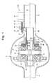
- FIG. 1is a sectional side view of a locking differential assembly in accordance with a first embodiment of a present invention
- FIG. 2is a top view of the locking differential assembly of the present invention
- FIG. 3is a sectional side view of the locking differential assembly in accordance with a second embodiment of the present invention.
- FIGS. 1 and 2 of the drawingsillustrate in detail the preferred arrangement of the differential assembly 10 in accordance with the present invention.
- Reference numeral 12defines a differential case rotatably supported in an axle housing 2 trough roller bearings (not shown), and defines an axis of rotation 14 .
- the axle housing 2has left and right axle shaft tubes 4 and 6 respectively, projecting coaxially from opposite sides.
- the differential assembly 10is provided with a set of pinion gears 16 rotatably supported on a pinion shaft 18 secured to the differential case 12 .
- the pinion gears 16engage a pair of opposite side gears 20 adapted to rotate about the axis 14 .
- the side gears 20are splined to output axle shafts (not shown) extending through a pair of opposite trunions 15 formed with the differential case 12 .
- a friction clutch assembly 22is provided within the differential case 12 .
- the friction clutch assembly 22well known in the prior art, includes sets of alternating outer friction plates 24 and inner friction plates 26 .
- an outer circumference of the outer friction plates 24is provided with projections that non-rotatably engages corresponding grooves 28 formed in the differential case 12 .
- the outer friction plates 24are slideable in axial direction.
- the inner friction plates 26are splined to the side gear 20 so that the inner friction clutch plates 26 are non-rotatably, but axially slidably mounted on the side gear 20 .
- An annular actuator plate 30is provided to axially load the friction clutch plates 24 and 26 in order to actuate the friction clutch assembly 22 .
- the friction clutch assembly 22When the friction clutch assembly 22 is actuated, it completely restricts the movement of internal components of the differential, thereby providing full torque from the engine to both driving wheels.
- the differential assembly 10further comprises a linear actuator assembly 40 .
- the linear actuator assembly 40includes a linear actuator motor 41 and a non-rotatable pusher block 48 coupled to the linear actuator motor 41 so that an actuating motion of the actuator motor 41 is transformed to a linear motion of pusher block 48 . It will be appreciated that any types of appropriate linear motors that provide linear axial motion of the pusher block 48 are within the scope of the present invention.
- the preferred embodiment of the actuator motor 41comprises an electric servomotor 42 mounted to an exterior surface of the axle housing 2 .
- hydraulic or pneumatic rotary motorsmay be employed instead of the electric motor.
- the servomotor 42drives a drive screw 46 via a gear reducer 44 .
- the electric motor 42 and the gear reducer 44are mounted outside the differential case 12 to the axle housing 2 , preferably to the axle tube 6 .
- the drive screw 46is provided, preferably, with an acme screw thread.
- the drive screw 46is partially disposed in the pusher block 48 provided with a thread that complements the thread in the drive screw 46 .
- rotation of the drive screw 46causes corresponding axial movement of the pusher block 48 between a retracted position and an extended position.
- FIG. 3shows a helically grooved ball screw 46 ′ disposed in a pusher block 48 ′ and an inner portion of the pusher block 48 ′ is provided with a helical groove that complements the groove in the ball screw 46 ′ so as to receive a plurality of balls 50 .
- rotation of the ball screw 46 ′causes corresponding axial movement of the pusher block 48 ′.
- linear actuator motor 41may be employed, such as hydraulic or pneumatic power cylinders, electromagnetic linear actuator, and a manual linear actuator actuated by a vehicle operator.
- the pusher block 48is axially slideable but rotary constrained, so that the rotational motion of the drive screw 46 is transformed to the linear motion of the pusher block 48 .
- the preferred embodiment of the actuator assembly 40 of the present inventionincludes a clutch actuating sleeve 52 disposed at least partially within the trunnion 15 coaxially to the axis 14 .
- the actuating sleeve 52is secured to the pusher block 48 by welding or any other appropriate means well known in the prior art.
- the pusher block 48 and the actuating sleeve 52may be manufactured as an integral single-piece part.
- the pusher block 48is extending between the drive screw 46 and the actuating sleeve 52 through an elongated slot 8 in the axle tube 6 .
- a sleeve bearing 54 press-fitted within the trunnion 15is employed to guide the actuating sleeve 52 .
- the actuating sleeve 52is provided to apply an axial force to the annular actuator plate 30 in order to load the friction clutch assembly 22 .
- An axial thrust bearing 56is provided between the actuator plate 30 and the actuating sleeve 52 to reduce the friction because the actuator plate 30 rotates with the side gear 20 .
- the gear reducer 44rotates the drive screw 46 .
- the rotary motion of the drive screw 46is transmitted to the pusher block 48 which travels linearly along the drive screw 46 leftward in FIG. 1 from the retracted position and the extended position.
- the linear axial motion of the pusher block 48is transmitted to the actuator plate 30 via the actuating sleeve 52 thereby to compress the friction clutch plates 24 and 26 in order to actuate the friction clutch assembly 22 and lock the differential assembly 10 .
- the externally actuated differential assembly in accordance with the present inventionrepresents a novel arrangement of the locking differential assembly that is simple, compact and inexpensive in manufacturing.
Landscapes
- Engineering & Computer Science (AREA)
- General Engineering & Computer Science (AREA)
- Mechanical Engineering (AREA)
- Physics & Mathematics (AREA)
- Electromagnetism (AREA)
- Retarders (AREA)
Abstract
Description
Claims (14)
Priority Applications (3)
| Application Number | Priority Date | Filing Date | Title |
|---|---|---|---|
| US09/670,810US6503167B1 (en) | 2000-09-28 | 2000-09-28 | Externally actuated locking differential assembly |
| DE10147630ADE10147630A1 (en) | 2000-09-28 | 2001-09-27 | Locking differential assembly for motor vehicles has electronic control and externally actuated friction clutch |
| JP2001301057AJP2002168321A (en) | 2000-09-28 | 2001-09-28 | Locking differential assembly |
Applications Claiming Priority (1)
| Application Number | Priority Date | Filing Date | Title |
|---|---|---|---|
| US09/670,810US6503167B1 (en) | 2000-09-28 | 2000-09-28 | Externally actuated locking differential assembly |
Publications (1)
| Publication Number | Publication Date |
|---|---|
| US6503167B1true US6503167B1 (en) | 2003-01-07 |
Family
ID=24691971
Family Applications (1)
| Application Number | Title | Priority Date | Filing Date |
|---|---|---|---|
| US09/670,810Expired - Fee RelatedUS6503167B1 (en) | 2000-09-28 | 2000-09-28 | Externally actuated locking differential assembly |
Country Status (3)
| Country | Link |
|---|---|
| US (1) | US6503167B1 (en) |
| JP (1) | JP2002168321A (en) |
| DE (1) | DE10147630A1 (en) |
Cited By (82)
| Publication number | Priority date | Publication date | Assignee | Title |
|---|---|---|---|---|
| US20030054914A1 (en)* | 2001-09-19 | 2003-03-20 | Honda Giken Kogyo Kabushiki Kaisha | Limited slip differential |
| US20040023742A1 (en)* | 2002-08-02 | 2004-02-05 | Visteon Global Technologies, Inc. | Selectively controlled limited slip differential |
| US20040050643A1 (en)* | 2002-09-12 | 2004-03-18 | Krzesicki Richard M. | Clutch actuator |
| US20040200655A1 (en)* | 2003-04-08 | 2004-10-14 | Mueller Joseph G. | On-demand transfer case |
| US20050070393A1 (en)* | 2003-09-29 | 2005-03-31 | Degowske Robert J. | Locking differential with electromagnetic actuator |
| US20050070395A1 (en)* | 2003-09-29 | 2005-03-31 | Degowske Robert J. | Electromagnetic locking differential assembly |
| US20050096172A1 (en)* | 2003-10-30 | 2005-05-05 | Mueller Joseph G. | Two-speed transfer case with adaptive clutch control |
| US20050113203A1 (en)* | 2003-11-24 | 2005-05-26 | Mueller Joseph G. | Clutch actuation system for two-speed active transfer case |
| US20060128515A1 (en)* | 2003-11-24 | 2006-06-15 | Mueller Joseph G | Two-speed transfer case |
| US20070049451A1 (en)* | 2005-09-01 | 2007-03-01 | Magna Powertrain Usa, Inc. | Two-speed transfer case with ballramp clutch actuator |
| US20070251345A1 (en)* | 2006-04-26 | 2007-11-01 | Magna Powertrain Ag & Co Kg | Two-Speed Transfer Case With Adaptive Torque Transfer Clutch |
| US20080045371A1 (en)* | 2006-08-21 | 2008-02-21 | American Axle & Manufacturing, Inc. | Axle assembly with electronic locking differential |
| US20080182702A1 (en)* | 2007-01-31 | 2008-07-31 | American Axle & Manufacturing, Inc. | Electronic locking differential with direct locking state detection system |
| US20090250284A1 (en)* | 2008-04-02 | 2009-10-08 | Shigehiro Mochizuki | Small-sized vehicle with improved drivetrain |
| US7650808B2 (en) | 2006-02-03 | 2010-01-26 | Magna Powertrain Usa, Inc. | Sprial cam clutch actuation system for two-speed transfer case |
| US20110017540A1 (en)* | 2009-07-24 | 2011-01-27 | King Darin D | Differential assembly including differential lock and blocking member |
| US20110233026A1 (en)* | 2010-03-26 | 2011-09-29 | Means Industries, Inc. | Overrunning coupling and control assembly including an electromechanical actuator subassembly |
| US20110269595A1 (en)* | 2010-04-30 | 2011-11-03 | American Axle & Manufacturing Inc. | Control strategy for operating a locking differential |
| US8646587B2 (en) | 2010-12-10 | 2014-02-11 | Means Industries, Inc. | Strut for a controllable one-way clutch |
| US8813929B2 (en) | 2010-12-10 | 2014-08-26 | Means Industries, Inc. | Controllable coupling assembly |
| US8888637B2 (en) | 2010-12-10 | 2014-11-18 | Means Industries, Inc. | Vehicle drive system including a transmission |
| US20150111684A1 (en)* | 2012-10-10 | 2015-04-23 | Eaton Corporation | Differential having piston housing integrated with differential case |
| CN104712728A (en)* | 2013-12-16 | 2015-06-17 | E-Aam传动系统公司 | Actuator coupling mechanism |
| US9109636B2 (en) | 2007-10-12 | 2015-08-18 | Means Industries, Inc. | Electromechanically actuated coupling and control assembly |
| US9121454B2 (en) | 2012-10-12 | 2015-09-01 | Means Industries, Inc. | Overrunning coupling and control assembly, coupling assembly and locking member for use therein |
| US9127724B2 (en) | 2010-12-10 | 2015-09-08 | Means Industries, Inc. | Electromechanical apparatus for use with a coupling assembly and controllable coupling assembly including such apparatus |
| US9186977B2 (en) | 2011-08-26 | 2015-11-17 | Means Industries, Inc. | Drive system including a transmission for a hybrid electric vehicle |
| US9188170B2 (en) | 2012-04-18 | 2015-11-17 | Means Industries, Inc. | Coupling and control assembly |
| US9234552B2 (en) | 2010-12-10 | 2016-01-12 | Means Industries, Inc. | Magnetic system for controlling the operating mode of an overrunning coupling assembly and overrunning coupling and magnetic control assembly having same |
| WO2016014827A1 (en)* | 2014-07-25 | 2016-01-28 | Eaton Corporation | Compact electronically controlled front wheel drive torque vectoring system with single or dual axle modulation |
| WO2016014823A1 (en)* | 2014-07-25 | 2016-01-28 | Eaton Corporation | Electromechanical clutch actuation system for limited slip differential |
| US9255614B2 (en) | 2010-12-10 | 2016-02-09 | Means Industries, Inc. | Electronic vehicular transmission and coupling and control assembly for use therein |
| US9303699B2 (en) | 2010-12-10 | 2016-04-05 | Means Industries, Inc. | Electromechanical assembly to control the operating mode of a coupling apparatus |
| US9371868B2 (en) | 2013-08-27 | 2016-06-21 | Means Industries, Inc. | Coupling member subassembly for use in controllable coupling assembly and electromechanical apparatus having a pair of simultaneously actuated elements for use in the subassembly |
| US9377061B2 (en) | 2010-12-10 | 2016-06-28 | Means Industries, Inc. | Electromagnetic system for controlling the operating mode of an overrunning coupling assembly and overrunning coupling and control assembly including the system |
| US9435387B2 (en) | 2010-12-10 | 2016-09-06 | Means Industries, Inc. | Device and apparatus for controlling the operating mode of a coupling assembly, coupling and control assembly and electric motor disconnect and pass through assemblies |
| US9441708B2 (en) | 2010-12-10 | 2016-09-13 | Means Industries, Inc. | High-efficiency drive system including a transmission for a hybrid electric vehicle |
| US9482294B2 (en) | 2014-02-19 | 2016-11-01 | Means Industries, Inc. | Coupling and control assembly including a sensor |
| US9482297B2 (en) | 2015-04-01 | 2016-11-01 | Means Industries, Inc. | Controllable coupling assembly having forward and reverse backlash |
| US9541141B2 (en) | 2010-12-10 | 2017-01-10 | Means Industries, Inc. | Electronic vehicular transmission, controllable coupling assembly and coupling member for use in the assembly |
| US9562574B2 (en) | 2014-02-19 | 2017-02-07 | Means Industries, Inc. | Controllable coupling assembly and coupling member for use in the assembly |
| US9638266B2 (en) | 2010-12-10 | 2017-05-02 | Means Industries, Inc. | Electronic vehicular transmission including a sensor and coupling and control assembly for use therein |
| RU173594U1 (en)* | 2017-04-19 | 2017-08-31 | Дмитрий Владимирович Винокуров | MECHANISM OF FORCED ELECTROMECHANICAL BLOCKING OF THE DIFFERENTIAL OF THE REDUCER OF THE CAR BRIDGE |
| US20170311464A1 (en) | 2016-04-26 | 2017-10-26 | Microsoft Technology Licensing, Llc | Structural device cover |
| US9874252B2 (en) | 2010-12-10 | 2018-01-23 | Means Industries, Inc. | Electronic, high-efficiency vehicular transmission, overrunning, non-friction coupling and control assembly and switchable linear actuator device for use therein |
| US9936593B2 (en) | 2016-04-14 | 2018-04-03 | Microsoft Technology Licensing, Llc | Device with a rotatable display |
| US9933049B2 (en) | 2012-10-04 | 2018-04-03 | Means Industries, Inc. | Vehicle drive system including a transmission |
| US9946309B2 (en) | 2016-06-10 | 2018-04-17 | Microsoft Technology Licensing, Llc | Device wiring |
| WO2018144185A1 (en) | 2017-02-02 | 2018-08-09 | Means Industries, Inc. | Overrunning, non-friction coupling and control assemblies and switchable linear actuator device and reciprocating electromechanical apparatus for use therein |
| US20180259050A1 (en)* | 2017-03-08 | 2018-09-13 | Thomson Industries, Inc. | Differential lock actuation and control |
| RU183429U1 (en)* | 2018-05-14 | 2018-09-21 | Роман Александрович Кузин | Front-wheel differential |
| RU185596U1 (en)* | 2018-03-30 | 2018-12-11 | Руслан Ахмадиевич Айтыкин | Limited slip differential |
| US10159158B2 (en) | 2016-04-14 | 2018-12-18 | Microsoft Technology Licensing, Llc | Device with a rotatable display |
| US10172248B1 (en) | 2016-04-14 | 2019-01-01 | Microsoft Technology Licensing, Llc | Device with a rotatable display |
| US20190024771A1 (en)* | 2017-07-19 | 2019-01-24 | Zhejiang CFMOTO Power Co., Ltd. | Locking Differential With In-Line, In-Profile Locking Drive Motor |
| US10221898B2 (en) | 2016-07-01 | 2019-03-05 | Microsoft Technology Licensing, Llc | Hinge clutch |
| US20190120247A1 (en)* | 2017-10-23 | 2019-04-25 | Swiss Module Group Llc | Deployable Fan with Linear Actuator |
| US10345851B2 (en) | 2016-04-14 | 2019-07-09 | Microsoft Technology Licensing, Llc | Device with a rotatable display |
| US10415681B2 (en)* | 2017-01-06 | 2019-09-17 | Team Industries, Inc. | Linear actuator |
| CN110645332A (en)* | 2019-04-30 | 2020-01-03 | 温岭市华鑫机械制造有限公司 | Integrated timely four-wheel drive differential assembly |
| US10527147B2 (en) | 2012-10-10 | 2020-01-07 | Eaton Corporation | Differential having compact bevel cross shaft retention using internal retainers |
| US10533618B2 (en) | 2013-09-26 | 2020-01-14 | Means Industries, Inc. | Overrunning, non-friction coupling and control assembly, engageable coupling assembly and locking member for use in the assemblies |
| US10591000B2 (en) | 2016-05-24 | 2020-03-17 | Means Industries, Inc. | One-way clutch assembly and coupling member for therein wherein locking member dynamics with respect to strut laydown speed are enhanced |
| US10590999B2 (en) | 2017-06-01 | 2020-03-17 | Means Industries, Inc. | Overrunning, non-friction, radial coupling and control assembly and switchable linear actuator device for use in the assembly |
| WO2020072429A1 (en) | 2018-10-04 | 2020-04-09 | Means Industries, Inc. | Coupling and control assembly having an internal latching mechanism |
| US10619681B2 (en) | 2014-09-16 | 2020-04-14 | Means Industries, Inc. | Overrunning, non-friction coupling and control assemblies and switchable linear actuator device and reciprocating electromechanical apparatus for use therein |
| US10677296B2 (en) | 2010-12-10 | 2020-06-09 | Means Industries, Inc. | Electronic, high-efficiency vehicular transmission, overrunning, non-friction coupling and control assembly and switchable linear actuator device for use therein |
| DE112018002499T5 (en) | 2017-05-15 | 2020-07-02 | Means Industries, Inc. | ONE-WAY CLUTCH AND CONTROL ARRANGEMENT; CLUTCH ARRANGEMENT AND LOCKING ELEMENT FOR USE THEREFORE WITH IMPROVED DYNAMICS RELATING TO THE DISPLACEMENT SPEED OF THE LOCKING ELEMENT |
| US10996710B2 (en) | 2016-04-14 | 2021-05-04 | Microsoft Technology Licensing, Llc | Device with a rotatable display |
| US10995803B2 (en) | 2018-12-04 | 2021-05-04 | Means Industries, Inc. | Electromagnetic system for controlling the operating mode of a non friction coupling assembly and coupling and magnetic control assembly having same |
| US11035423B2 (en) | 2017-02-02 | 2021-06-15 | Means Industries, Inc. | Non-friction coupling and control assembly, engageable coupling assembly and locking member for use in the assemblies |
| DE112019005284T5 (en) | 2018-10-23 | 2021-07-08 | Means Industries, Inc. | HIGH SPEED FREE-ROTATING CLUTCH AND CONTROL ASSEMBLY, CLUTCH ASSEMBLY AND LOCKING PART THAT MOVES WITH SIGNIFICANTLY REDUCED FRICTION |
| DE102021102824A1 (en) | 2020-02-12 | 2021-08-12 | Means Industries, Inc. | ELECTRODYNAMIC CLUTCH AND CONTROL ASSEMBLY AND SWITCHABLE LINEAR ACTUATOR FOR USE IN THIS |
| DE102021107969A1 (en) | 2020-03-31 | 2021-09-30 | Means Industries, Inc. | COUPLING AND CONTROL UNIT WITH A CONTACTLESS, INDUCTIVE POSITION SENSOR |
| DE102021104228A1 (en) | 2020-03-31 | 2021-09-30 | Means Industries, Inc. | Coupling and control arrangement with a non-contact, linear inductive position sensor |
| DE112020000732T5 (en) | 2019-02-08 | 2021-10-28 | Means Industries, Inc. | FRICTION-FREE CLUTCH AND CONTROL ARRANGEMENT, LOCKING CLUTCH ARRANGEMENT AND LOCKING PART FOR USE IN THE ARRANGEMENTS |
| CN113669428A (en)* | 2021-07-20 | 2021-11-19 | 一汽解放汽车有限公司 | Electric differential lock |
| US11215245B2 (en) | 2019-12-03 | 2022-01-04 | Means Industries, Inc. | Coupling and control assembly including controllable coupling assembly having speed sensor and methods of controlling the controllable coupling assembly using information from the speed sensor for park/hill-hold operations |
| US11346433B2 (en) | 2020-01-03 | 2022-05-31 | Zhejiang CFMOTO Power Co., Ltd. | Actuator for differential mode shift with spring linkage |
| CN114704607A (en)* | 2022-03-25 | 2022-07-05 | 蔚来动力科技(合肥)有限公司 | Disconnecting differential and electric drive transmission system with same |
| US11542992B2 (en) | 2020-03-31 | 2023-01-03 | Means Industries, Inc. | Coupling and control assembly including a non-contact, linear inductive position sensor |
| US11874142B2 (en) | 2020-03-31 | 2024-01-16 | Means Industries, Inc. | Coupling and control assembly including a position sensor |
Families Citing this family (4)
| Publication number | Priority date | Publication date | Assignee | Title |
|---|---|---|---|---|
| FR2844858B1 (en)* | 2002-09-25 | 2006-12-29 | Peugeot Citroen Automobiles Sa | ASYMMETRIC DIFFERENTIAL WITH ACTIVE CHARACTER FOR MOTOR VEHICLE |
| CN104534086B (en)* | 2014-12-23 | 2017-04-12 | 东风汽车公司 | Electronically-control type differential lock control mechanism and method |
| EP3045776A1 (en)* | 2015-01-13 | 2016-07-20 | Tollo Linear AB | Failsafe electrical actuator for a differential locking system |
| JP6852608B2 (en)* | 2017-07-21 | 2021-03-31 | トヨタ自動車株式会社 | Differential limiting device for vehicle differential gears |
Citations (10)
| Publication number | Priority date | Publication date | Assignee | Title |
|---|---|---|---|---|
| US4679463A (en)* | 1984-08-31 | 1987-07-14 | Nissan Motor Co., Ltd. | Limited slip differential |
| US4805486A (en) | 1986-06-04 | 1989-02-21 | Tochigifujisangyo Kabushiki Kaisha | Locking differential gear assembly |
| US4838118A (en)* | 1988-03-10 | 1989-06-13 | Eaton Corporation | Anti-spin differential |
| US4895236A (en) | 1987-02-02 | 1990-01-23 | Aisin-Warner Kabushiki Kaisha | Actuator for the frictional engaging device |
| US4976347A (en) | 1987-12-10 | 1990-12-11 | Aisin Aw Co., Ltd. | Actuator for friction engagement device |
| US5019021A (en)* | 1990-07-02 | 1991-05-28 | Eaton Corporation | Modulating limited slip differential |
| US5199325A (en) | 1991-09-12 | 1993-04-06 | Dana Corporation | Electronic shift or clutch actuator for a vehicle transmission |
| US5267635A (en)* | 1992-07-13 | 1993-12-07 | Automotive Products Plc | Clutch actuator system |
| US5279401A (en)* | 1988-11-08 | 1994-01-18 | Uni-Cardan Ag | Method for controlling friction clutches or brakes |
| US5299986A (en)* | 1991-01-21 | 1994-04-05 | Carraro S.P.A. | Differential lock device |
- 2000
- 2000-09-28USUS09/670,810patent/US6503167B1/ennot_activeExpired - Fee Related
- 2001
- 2001-09-27DEDE10147630Apatent/DE10147630A1/ennot_activeWithdrawn
- 2001-09-28JPJP2001301057Apatent/JP2002168321A/enactivePending
Patent Citations (10)
| Publication number | Priority date | Publication date | Assignee | Title |
|---|---|---|---|---|
| US4679463A (en)* | 1984-08-31 | 1987-07-14 | Nissan Motor Co., Ltd. | Limited slip differential |
| US4805486A (en) | 1986-06-04 | 1989-02-21 | Tochigifujisangyo Kabushiki Kaisha | Locking differential gear assembly |
| US4895236A (en) | 1987-02-02 | 1990-01-23 | Aisin-Warner Kabushiki Kaisha | Actuator for the frictional engaging device |
| US4976347A (en) | 1987-12-10 | 1990-12-11 | Aisin Aw Co., Ltd. | Actuator for friction engagement device |
| US4838118A (en)* | 1988-03-10 | 1989-06-13 | Eaton Corporation | Anti-spin differential |
| US5279401A (en)* | 1988-11-08 | 1994-01-18 | Uni-Cardan Ag | Method for controlling friction clutches or brakes |
| US5019021A (en)* | 1990-07-02 | 1991-05-28 | Eaton Corporation | Modulating limited slip differential |
| US5299986A (en)* | 1991-01-21 | 1994-04-05 | Carraro S.P.A. | Differential lock device |
| US5199325A (en) | 1991-09-12 | 1993-04-06 | Dana Corporation | Electronic shift or clutch actuator for a vehicle transmission |
| US5267635A (en)* | 1992-07-13 | 1993-12-07 | Automotive Products Plc | Clutch actuator system |
Cited By (145)
| Publication number | Priority date | Publication date | Assignee | Title |
|---|---|---|---|---|
| US6857982B2 (en)* | 2001-09-19 | 2005-02-22 | Honda Giken Kogyo Kabushiki Kaisha | Limited slip differential |
| US20030054914A1 (en)* | 2001-09-19 | 2003-03-20 | Honda Giken Kogyo Kabushiki Kaisha | Limited slip differential |
| US20040023742A1 (en)* | 2002-08-02 | 2004-02-05 | Visteon Global Technologies, Inc. | Selectively controlled limited slip differential |
| US6805653B2 (en)* | 2002-08-02 | 2004-10-19 | Visteon Global Technologies, Inc. | Selectively controlled limited slip differential |
| US20040050643A1 (en)* | 2002-09-12 | 2004-03-18 | Krzesicki Richard M. | Clutch actuator |
| US6964315B2 (en) | 2003-04-08 | 2005-11-15 | Magnadrivetrain Of America, Inc. | On-demand transfer case |
| US20040200655A1 (en)* | 2003-04-08 | 2004-10-14 | Mueller Joseph G. | On-demand transfer case |
| US6808037B1 (en) | 2003-04-08 | 2004-10-26 | New Venture Gear, Inc. | On-demand transfer case |
| US20050023063A1 (en)* | 2003-04-08 | 2005-02-03 | Mueller Joseph G. | On-demand transfer case |
| US7178652B2 (en) | 2003-04-08 | 2007-02-20 | Magna Powertrain Usa, Inc. | Power transmission device having torque transfer mechanism with power-operated clutch actuator |
| US20060054373A1 (en)* | 2003-04-08 | 2006-03-16 | Mueller Joseph G | Power transmission device having torque transfer mechanism with power-operated clutch actuator |
| US20050070393A1 (en)* | 2003-09-29 | 2005-03-31 | Degowske Robert J. | Locking differential with electromagnetic actuator |
| US7022040B2 (en) | 2003-09-29 | 2006-04-04 | American Axle & Manufacturing, Inc. | Locking differential with electromagnetic actuator |
| US7201696B2 (en) | 2003-09-29 | 2007-04-10 | American Axle & Manufacturing, Inc. | Differential with electromagnetic clutch assembly |
| US20050070395A1 (en)* | 2003-09-29 | 2005-03-31 | Degowske Robert J. | Electromagnetic locking differential assembly |
| US6958030B2 (en) | 2003-09-29 | 2005-10-25 | American Axle & Manufacturing, Inc. | Electromagnetic locking differential assembly |
| US20070037654A1 (en)* | 2003-09-29 | 2007-02-15 | American Axle & Manufacturing, Inc. | Differential with electromagnetic clutch assembly |
| US20050277508A1 (en)* | 2003-09-29 | 2005-12-15 | Degowske Robert J | Electromagnetic locking differential assembly |
| US7137921B2 (en) | 2003-09-29 | 2006-11-21 | American Axle & Manufacturing, Inc. | Electromagnetic locking differential assembly |
| US7081064B2 (en) | 2003-10-30 | 2006-07-25 | Magna Powertrain Usa, Inc. | Two-speed transfer case with adaptive clutch control |
| US7229378B2 (en) | 2003-10-30 | 2007-06-12 | Magna Powertrain Usa, Inc. | Shift system for transfer case |
| US20050096172A1 (en)* | 2003-10-30 | 2005-05-05 | Mueller Joseph G. | Two-speed transfer case with adaptive clutch control |
| US6905436B2 (en) | 2003-10-30 | 2005-06-14 | Magna Drivetrain Of America, Inc. | Two-speed transfer case with adaptive clutch control |
| US20060247082A1 (en)* | 2003-10-30 | 2006-11-02 | Magna Powertrain Usa, Inc. | Shift system for transfer case |
| US20060128515A1 (en)* | 2003-11-24 | 2006-06-15 | Mueller Joseph G | Two-speed transfer case |
| US20050113203A1 (en)* | 2003-11-24 | 2005-05-26 | Mueller Joseph G. | Clutch actuation system for two-speed active transfer case |
| US20050202919A1 (en)* | 2003-11-24 | 2005-09-15 | Mueller Joseph G. | Clutch actuation system for two-speed active transfer case |
| US6929577B2 (en) | 2003-11-24 | 2005-08-16 | Magna Drivetrain Of America, Inc. | Clutch actuation system for two-speed active transfer case |
| US7033300B2 (en) | 2003-11-24 | 2006-04-25 | Magna Powertrain, Inc. | Clutch actuation system for two-speed active transfer case |
| US7399251B2 (en) | 2003-11-24 | 2008-07-15 | Magna Powertrain Usa, Inc. | Two-speed transfer case |
| US20070049451A1 (en)* | 2005-09-01 | 2007-03-01 | Magna Powertrain Usa, Inc. | Two-speed transfer case with ballramp clutch actuator |
| US7540820B2 (en) | 2005-09-01 | 2009-06-02 | Magna Powertrain Usa, Inc. | Two-speed transfer case with ballramp clutch actuator |
| US7650808B2 (en) | 2006-02-03 | 2010-01-26 | Magna Powertrain Usa, Inc. | Sprial cam clutch actuation system for two-speed transfer case |
| US20070251345A1 (en)* | 2006-04-26 | 2007-11-01 | Magna Powertrain Ag & Co Kg | Two-Speed Transfer Case With Adaptive Torque Transfer Clutch |
| US7694598B2 (en) | 2006-04-26 | 2010-04-13 | Magna Powertrain Ag & Co Kg | Two-speed transfer case with adaptive torque transfer clutch |
| US7534187B2 (en) | 2006-08-21 | 2009-05-19 | American Axle & Manufacturing, Inc. | Locking differential assembly |
| US7764154B2 (en) | 2006-08-21 | 2010-07-27 | American Axle & Manufacturing, Inc. | Electronically actuated apparatus using solenoid actuator with integrated sensor |
| US20080045371A1 (en)* | 2006-08-21 | 2008-02-21 | American Axle & Manufacturing, Inc. | Axle assembly with electronic locking differential |
| US7425185B2 (en) | 2006-08-21 | 2008-09-16 | American Axle & Manufacturing, Inc. | Axle assembly with electronic locking differential |
| US20090011889A1 (en)* | 2006-08-21 | 2009-01-08 | American Axle & Manufacturing, Inc. | Locking Differential Assembly |
| US7876186B2 (en) | 2006-08-21 | 2011-01-25 | American Axle & Manufacturing, Inc. | Electronically actuated apparatus |
| US20100283566A1 (en)* | 2006-08-21 | 2010-11-11 | Todd Michael York | Electronically actuated apparatus |
| US7602271B2 (en) | 2006-08-21 | 2009-10-13 | American Axle & Manufacturing, Inc. | Electronically actuated apparatus using solenoid actuator with integrated sensor |
| US20100013582A1 (en)* | 2006-08-21 | 2010-01-21 | Todd Michael York | Electronically actuated apparatus using solenoid actuator with integrated sensor |
| US7825759B2 (en) | 2006-08-21 | 2010-11-02 | American Axle & Manufacturing, Inc. | Annular actuator having plunger configured to translate through a viscous liquid |
| US7682279B2 (en) | 2006-08-21 | 2010-03-23 | American Axle & Manufacturing, Inc. | Electronically actuated apparatus using solenoid actuator with integrated sensor |
| US20080042791A1 (en)* | 2006-08-21 | 2008-02-21 | American Axle & Manufacturing, Inc. | Electronically actuated apparatus using solenoid actuator with integrated sensor |
| US7785224B2 (en) | 2006-08-21 | 2010-08-31 | American Axle & Manufacturing, Inc. | Annular solenoid with axially overlapping electromagnet and armature |
| US7942780B2 (en) | 2007-01-31 | 2011-05-17 | American Axle & Manufacturing, Inc. | Electronic locking differential with direct locking state detection system |
| US7744500B2 (en) | 2007-01-31 | 2010-06-29 | American Axle & Manufacturing, Inc. | Electronic locking differential with direct locking state detection system |
| US20080182702A1 (en)* | 2007-01-31 | 2008-07-31 | American Axle & Manufacturing, Inc. | Electronic locking differential with direct locking state detection system |
| US20110009223A1 (en)* | 2007-01-31 | 2011-01-13 | Donofrio Gregory M | Electronic locking differential with direct locking state detection system |
| US20090247350A1 (en)* | 2007-01-31 | 2009-10-01 | Donofrio Gregory M | Electronic locking differential with direct locking state detection system |
| US7572202B2 (en) | 2007-01-31 | 2009-08-11 | American Axle & Manufacturing, Inc. | Electronic locking differential with direct locking state detection system |
| US9109636B2 (en) | 2007-10-12 | 2015-08-18 | Means Industries, Inc. | Electromechanically actuated coupling and control assembly |
| US7896120B2 (en)* | 2008-04-02 | 2011-03-01 | Yamaha Hatsudoki Kabushiki Kaisha | Small-sized vehicle with improved drivetrain |
| US20090250284A1 (en)* | 2008-04-02 | 2009-10-08 | Shigehiro Mochizuki | Small-sized vehicle with improved drivetrain |
| US20110017540A1 (en)* | 2009-07-24 | 2011-01-27 | King Darin D | Differential assembly including differential lock and blocking member |
| US8152672B2 (en)* | 2009-07-24 | 2012-04-10 | Honda Motor Company, Ltd. | Differential assembly including differential lock and blocking member |
| US20110233026A1 (en)* | 2010-03-26 | 2011-09-29 | Means Industries, Inc. | Overrunning coupling and control assembly including an electromechanical actuator subassembly |
| US8720659B2 (en) | 2010-03-26 | 2014-05-13 | Means Industries, Inc. | Overrunning coupling and control assembly including an electromechanical actuator subassembly |
| US20110269595A1 (en)* | 2010-04-30 | 2011-11-03 | American Axle & Manufacturing Inc. | Control strategy for operating a locking differential |
| US8888637B2 (en) | 2010-12-10 | 2014-11-18 | Means Industries, Inc. | Vehicle drive system including a transmission |
| US9127724B2 (en) | 2010-12-10 | 2015-09-08 | Means Industries, Inc. | Electromechanical apparatus for use with a coupling assembly and controllable coupling assembly including such apparatus |
| US10677296B2 (en) | 2010-12-10 | 2020-06-09 | Means Industries, Inc. | Electronic, high-efficiency vehicular transmission, overrunning, non-friction coupling and control assembly and switchable linear actuator device for use therein |
| US9874252B2 (en) | 2010-12-10 | 2018-01-23 | Means Industries, Inc. | Electronic, high-efficiency vehicular transmission, overrunning, non-friction coupling and control assembly and switchable linear actuator device for use therein |
| US9638266B2 (en) | 2010-12-10 | 2017-05-02 | Means Industries, Inc. | Electronic vehicular transmission including a sensor and coupling and control assembly for use therein |
| US8646587B2 (en) | 2010-12-10 | 2014-02-11 | Means Industries, Inc. | Strut for a controllable one-way clutch |
| US9541141B2 (en) | 2010-12-10 | 2017-01-10 | Means Industries, Inc. | Electronic vehicular transmission, controllable coupling assembly and coupling member for use in the assembly |
| US8813929B2 (en) | 2010-12-10 | 2014-08-26 | Means Industries, Inc. | Controllable coupling assembly |
| US9303699B2 (en) | 2010-12-10 | 2016-04-05 | Means Industries, Inc. | Electromechanical assembly to control the operating mode of a coupling apparatus |
| US9377061B2 (en) | 2010-12-10 | 2016-06-28 | Means Industries, Inc. | Electromagnetic system for controlling the operating mode of an overrunning coupling assembly and overrunning coupling and control assembly including the system |
| US9234552B2 (en) | 2010-12-10 | 2016-01-12 | Means Industries, Inc. | Magnetic system for controlling the operating mode of an overrunning coupling assembly and overrunning coupling and magnetic control assembly having same |
| US9441708B2 (en) | 2010-12-10 | 2016-09-13 | Means Industries, Inc. | High-efficiency drive system including a transmission for a hybrid electric vehicle |
| US9435387B2 (en) | 2010-12-10 | 2016-09-06 | Means Industries, Inc. | Device and apparatus for controlling the operating mode of a coupling assembly, coupling and control assembly and electric motor disconnect and pass through assemblies |
| US9255614B2 (en) | 2010-12-10 | 2016-02-09 | Means Industries, Inc. | Electronic vehicular transmission and coupling and control assembly for use therein |
| US9186977B2 (en) | 2011-08-26 | 2015-11-17 | Means Industries, Inc. | Drive system including a transmission for a hybrid electric vehicle |
| US9188170B2 (en) | 2012-04-18 | 2015-11-17 | Means Industries, Inc. | Coupling and control assembly |
| US9933049B2 (en) | 2012-10-04 | 2018-04-03 | Means Industries, Inc. | Vehicle drive system including a transmission |
| US10323739B2 (en) | 2012-10-10 | 2019-06-18 | Eaton Corporation | Differential having externally mounted plenum |
| US10527147B2 (en) | 2012-10-10 | 2020-01-07 | Eaton Corporation | Differential having compact bevel cross shaft retention using internal retainers |
| US20150111684A1 (en)* | 2012-10-10 | 2015-04-23 | Eaton Corporation | Differential having piston housing integrated with differential case |
| US9709150B2 (en)* | 2012-10-10 | 2017-07-18 | Eaton Corporation | Differential having piston housing integrated with differential case |
| US9121454B2 (en) | 2012-10-12 | 2015-09-01 | Means Industries, Inc. | Overrunning coupling and control assembly, coupling assembly and locking member for use therein |
| US9371868B2 (en) | 2013-08-27 | 2016-06-21 | Means Industries, Inc. | Coupling member subassembly for use in controllable coupling assembly and electromechanical apparatus having a pair of simultaneously actuated elements for use in the subassembly |
| US10533618B2 (en) | 2013-09-26 | 2020-01-14 | Means Industries, Inc. | Overrunning, non-friction coupling and control assembly, engageable coupling assembly and locking member for use in the assemblies |
| US20150166035A1 (en)* | 2013-12-16 | 2015-06-18 | Eaam Driveline Systems Ab | Actuator coupling mechanism |
| CN104712728A (en)* | 2013-12-16 | 2015-06-17 | E-Aam传动系统公司 | Actuator coupling mechanism |
| US9353852B2 (en)* | 2013-12-16 | 2016-05-31 | E-Aam Driveline Systems Ab | Actuator coupling mechanism |
| US9562574B2 (en) | 2014-02-19 | 2017-02-07 | Means Industries, Inc. | Controllable coupling assembly and coupling member for use in the assembly |
| US9482294B2 (en) | 2014-02-19 | 2016-11-01 | Means Industries, Inc. | Coupling and control assembly including a sensor |
| US20170130814A1 (en)* | 2014-07-25 | 2017-05-11 | Eaton Corporation | Electromechanical clutch actuation system for limited slip differential |
| CN106687716A (en)* | 2014-07-25 | 2017-05-17 | 伊顿公司 | Compact electronically controlled front wheel drive torque vectoring system with single or dual axis modulation |
| WO2016014827A1 (en)* | 2014-07-25 | 2016-01-28 | Eaton Corporation | Compact electronically controlled front wheel drive torque vectoring system with single or dual axle modulation |
| WO2016014823A1 (en)* | 2014-07-25 | 2016-01-28 | Eaton Corporation | Electromechanical clutch actuation system for limited slip differential |
| US10619681B2 (en) | 2014-09-16 | 2020-04-14 | Means Industries, Inc. | Overrunning, non-friction coupling and control assemblies and switchable linear actuator device and reciprocating electromechanical apparatus for use therein |
| US9482297B2 (en) | 2015-04-01 | 2016-11-01 | Means Industries, Inc. | Controllable coupling assembly having forward and reverse backlash |
| US9936593B2 (en) | 2016-04-14 | 2018-04-03 | Microsoft Technology Licensing, Llc | Device with a rotatable display |
| US10345851B2 (en) | 2016-04-14 | 2019-07-09 | Microsoft Technology Licensing, Llc | Device with a rotatable display |
| US10996710B2 (en) | 2016-04-14 | 2021-05-04 | Microsoft Technology Licensing, Llc | Device with a rotatable display |
| US10159158B2 (en) | 2016-04-14 | 2018-12-18 | Microsoft Technology Licensing, Llc | Device with a rotatable display |
| US10172248B1 (en) | 2016-04-14 | 2019-01-01 | Microsoft Technology Licensing, Llc | Device with a rotatable display |
| US10999944B2 (en) | 2016-04-26 | 2021-05-04 | Microsoft Technology Licensing, Llc | Structural device cover |
| US20170311464A1 (en) | 2016-04-26 | 2017-10-26 | Microsoft Technology Licensing, Llc | Structural device cover |
| US10591000B2 (en) | 2016-05-24 | 2020-03-17 | Means Industries, Inc. | One-way clutch assembly and coupling member for therein wherein locking member dynamics with respect to strut laydown speed are enhanced |
| US9946309B2 (en) | 2016-06-10 | 2018-04-17 | Microsoft Technology Licensing, Llc | Device wiring |
| US10221898B2 (en) | 2016-07-01 | 2019-03-05 | Microsoft Technology Licensing, Llc | Hinge clutch |
| US10415681B2 (en)* | 2017-01-06 | 2019-09-17 | Team Industries, Inc. | Linear actuator |
| WO2018144185A1 (en) | 2017-02-02 | 2018-08-09 | Means Industries, Inc. | Overrunning, non-friction coupling and control assemblies and switchable linear actuator device and reciprocating electromechanical apparatus for use therein |
| US11035423B2 (en) | 2017-02-02 | 2021-06-15 | Means Industries, Inc. | Non-friction coupling and control assembly, engageable coupling assembly and locking member for use in the assemblies |
| US20180259050A1 (en)* | 2017-03-08 | 2018-09-13 | Thomson Industries, Inc. | Differential lock actuation and control |
| US10683921B2 (en)* | 2017-03-08 | 2020-06-16 | Thomson Industries, Inc. | Differential lock actuation and control |
| RU173594U1 (en)* | 2017-04-19 | 2017-08-31 | Дмитрий Владимирович Винокуров | MECHANISM OF FORCED ELECTROMECHANICAL BLOCKING OF THE DIFFERENTIAL OF THE REDUCER OF THE CAR BRIDGE |
| DE112018002499B4 (en) | 2017-05-15 | 2024-11-14 | Means Industries, Inc. | FREEWHEEL CLUTCH AND CONTROL ARRANGEMENT; CLUTCH ARRANGEMENT AND LOCKING ELEMENT FOR USE THEREIN WITH IMPROVED DYNAMICS IN RELATION TO THE RELEASE SPEED OF THE LOCKING ELEMENT |
| DE112018002499T5 (en) | 2017-05-15 | 2020-07-02 | Means Industries, Inc. | ONE-WAY CLUTCH AND CONTROL ARRANGEMENT; CLUTCH ARRANGEMENT AND LOCKING ELEMENT FOR USE THEREFORE WITH IMPROVED DYNAMICS RELATING TO THE DISPLACEMENT SPEED OF THE LOCKING ELEMENT |
| US10711853B2 (en) | 2017-05-15 | 2020-07-14 | Means Industries, Inc. | Overrunning coupling and control assembly, coupling assembly and locking member for use therein having improved dynamics with regards to locking member laydown speed |
| US10590999B2 (en) | 2017-06-01 | 2020-03-17 | Means Industries, Inc. | Overrunning, non-friction, radial coupling and control assembly and switchable linear actuator device for use in the assembly |
| US20190024771A1 (en)* | 2017-07-19 | 2019-01-24 | Zhejiang CFMOTO Power Co., Ltd. | Locking Differential With In-Line, In-Profile Locking Drive Motor |
| US10816071B2 (en)* | 2017-07-19 | 2020-10-27 | Zhejiang CFMOTO Power Co., Ltd. | Locking differential with in-line, in-profile locking drive motor |
| US10851798B2 (en)* | 2017-10-23 | 2020-12-01 | Swiss Module Group Llc | Deployable fan with linear actuator |
| US20190120247A1 (en)* | 2017-10-23 | 2019-04-25 | Swiss Module Group Llc | Deployable Fan with Linear Actuator |
| RU185596U1 (en)* | 2018-03-30 | 2018-12-11 | Руслан Ахмадиевич Айтыкин | Limited slip differential |
| RU183429U1 (en)* | 2018-05-14 | 2018-09-21 | Роман Александрович Кузин | Front-wheel differential |
| US10968964B2 (en) | 2018-10-04 | 2021-04-06 | Means Industries, Inc. | Coupling and control assembly having an internal latching mechanism |
| WO2020072429A1 (en) | 2018-10-04 | 2020-04-09 | Means Industries, Inc. | Coupling and control assembly having an internal latching mechanism |
| US11187282B2 (en) | 2018-10-23 | 2021-11-30 | Means Industries, Inc. | High-speed, overrunning coupling and control assembly, coupling assembly and locking member which pivotally moves with substantially reduced friction |
| DE112019005284T5 (en) | 2018-10-23 | 2021-07-08 | Means Industries, Inc. | HIGH SPEED FREE-ROTATING CLUTCH AND CONTROL ASSEMBLY, CLUTCH ASSEMBLY AND LOCKING PART THAT MOVES WITH SIGNIFICANTLY REDUCED FRICTION |
| US10995803B2 (en) | 2018-12-04 | 2021-05-04 | Means Industries, Inc. | Electromagnetic system for controlling the operating mode of a non friction coupling assembly and coupling and magnetic control assembly having same |
| DE112019006036T5 (en) | 2018-12-04 | 2021-09-30 | Means Industries, Inc. | Electromagnetic system for controlling the mode of operation of a frictionless clutch assembly and clutch and magnetic control assembly with the same |
| DE112020000732T5 (en) | 2019-02-08 | 2021-10-28 | Means Industries, Inc. | FRICTION-FREE CLUTCH AND CONTROL ARRANGEMENT, LOCKING CLUTCH ARRANGEMENT AND LOCKING PART FOR USE IN THE ARRANGEMENTS |
| CN110645332A (en)* | 2019-04-30 | 2020-01-03 | 温岭市华鑫机械制造有限公司 | Integrated timely four-wheel drive differential assembly |
| US11215245B2 (en) | 2019-12-03 | 2022-01-04 | Means Industries, Inc. | Coupling and control assembly including controllable coupling assembly having speed sensor and methods of controlling the controllable coupling assembly using information from the speed sensor for park/hill-hold operations |
| US11525500B2 (en) | 2020-01-03 | 2022-12-13 | Zhejiang Cfmoto Power Co. Ltd. | Internal structure of actuator for differential mode shift |
| US11346433B2 (en) | 2020-01-03 | 2022-05-31 | Zhejiang CFMOTO Power Co., Ltd. | Actuator for differential mode shift with spring linkage |
| US11353099B2 (en) | 2020-01-03 | 2022-06-07 | Zhejiang CFMOTO Power Co., Ltd. | Actuator for differential mode shift with position sensing circuit |
| US11674580B2 (en) | 2020-01-03 | 2023-06-13 | Zhejiang CFMOTO Power Co., Ltd. | Actuator for differential mode shift with pivot link |
| DE102021102824A1 (en) | 2020-02-12 | 2021-08-12 | Means Industries, Inc. | ELECTRODYNAMIC CLUTCH AND CONTROL ASSEMBLY AND SWITCHABLE LINEAR ACTUATOR FOR USE IN THIS |
| US11286996B2 (en) | 2020-02-12 | 2022-03-29 | Means Industries, Inc. | Electro-dynamic coupling and control assembly and switchable linear actuator device for use therein |
| US11953060B2 (en) | 2020-02-12 | 2024-04-09 | Means Industries, Inc. | Coupling and control assembly |
| DE102021104228A1 (en) | 2020-03-31 | 2021-09-30 | Means Industries, Inc. | Coupling and control arrangement with a non-contact, linear inductive position sensor |
| DE102021107969A1 (en) | 2020-03-31 | 2021-09-30 | Means Industries, Inc. | COUPLING AND CONTROL UNIT WITH A CONTACTLESS, INDUCTIVE POSITION SENSOR |
| US11542992B2 (en) | 2020-03-31 | 2023-01-03 | Means Industries, Inc. | Coupling and control assembly including a non-contact, linear inductive position sensor |
| US11874142B2 (en) | 2020-03-31 | 2024-01-16 | Means Industries, Inc. | Coupling and control assembly including a position sensor |
| CN113669428A (en)* | 2021-07-20 | 2021-11-19 | 一汽解放汽车有限公司 | Electric differential lock |
| CN114704607A (en)* | 2022-03-25 | 2022-07-05 | 蔚来动力科技(合肥)有限公司 | Disconnecting differential and electric drive transmission system with same |
Also Published As
| Publication number | Publication date |
|---|---|
| DE10147630A1 (en) | 2002-05-02 |
| JP2002168321A (en) | 2002-06-14 |
Similar Documents
| Publication | Publication Date | Title |
|---|---|---|
| US6503167B1 (en) | Externally actuated locking differential assembly | |
| US6398686B1 (en) | Electronically controlled limited slip differential assembly | |
| US6561939B1 (en) | Gear module for clutch actuator in differential assembly | |
| US6827663B2 (en) | Differential gear | |
| US6460677B1 (en) | Dual ball ramp actuator for locking differential | |
| US5556344A (en) | Limited slip differential with reduced preload | |
| KR102269033B1 (en) | Limited slip differential with separation of clutch and actuator | |
| US20170130814A1 (en) | Electromechanical clutch actuation system for limited slip differential | |
| US20100219034A1 (en) | Control assembly | |
| DE102009013875B4 (en) | Motor vehicle drive unit with two electric motors | |
| CN100441896C (en) | Electrohydraulic Clutch Assembly | |
| US5217416A (en) | Lock up/limited slip differential | |
| GB2424251A (en) | Front-wheel-drive transaxle with limited slip differential | |
| US20040110593A1 (en) | Power transmission with electromechanical actuator | |
| US4594913A (en) | Double-acting differential with slip limiting elements | |
| CN113653798A (en) | Two-gear electric control transfer case with locking mechanism | |
| US5616096A (en) | Differential gear unit | |
| US20220136569A1 (en) | Torque transmission device for a motor vehicle | |
| EP0284329B1 (en) | Improvements in differential mechanisms | |
| RU173594U1 (en) | MECHANISM OF FORCED ELECTROMECHANICAL BLOCKING OF THE DIFFERENTIAL OF THE REDUCER OF THE CAR BRIDGE | |
| CN211501536U (en) | Integrated timely four-wheel drive differential assembly | |
| US11306803B2 (en) | Vehicle drive unit assembly | |
| US5560268A (en) | Differential mechanism with lockable rotatable cam members | |
| EP3194808A1 (en) | Compact electronically controlled front wheel drive torque vectoring system with single or dual axle modulation | |
| KR102868346B1 (en) | Electric drive module with transmission having parallel twin gear pairs sharing load to a final drive gear |
Legal Events
| Date | Code | Title | Description |
|---|---|---|---|
| AS | Assignment | Owner name:SPICER TECHNOLOGIES, INC., INDIANA Free format text:ASSIGNMENT OF ASSIGNORS INTEREST;ASSIGNOR:STURM, GARY;REEL/FRAME:011162/0149 Effective date:20000927 | |
| AS | Assignment | Owner name:SPICER TECHNOLOGY, INC., INDIANA Free format text:ASSIGNMENT OF ASSIGNORS INTEREST;ASSIGNOR:STURM, GARY L.;REEL/FRAME:012510/0727 Effective date:20020124 | |
| AS | Assignment | Owner name:TORQUE-TRACTION TECHNOLOGIES, INC., OHIO Free format text:MERGER /CHANGE OF NAME;ASSIGNORS:SPICER TECHNOLOGY, INC.;SPICER DRIVESHAFT, INC.;REEL/FRAME:014646/0285 Effective date:20021231 Owner name:TORQUE-TRACTION TECHNOLOGIES, INC., OHIO Free format text:MERGER AND CHANGE OF NAME;ASSIGNORS:SPICER TECHNOLOGY, INC.;SPICER DRIVESHAFT, INC.;REEL/FRAME:013943/0214 Effective date:20021231 | |
| AS | Assignment | Owner name:TORQUE-TRACTION TECHNOLOGIES LLC, OHIO Free format text:MERGER;ASSIGNOR:TORQUE-TRACTION TECHNOLOGY, INC.;REEL/FRAME:017240/0209 Effective date:20060101 | |
| FPAY | Fee payment | Year of fee payment:4 | |
| AS | Assignment | Owner name:DANA AUTOMOTIVE SYSTEMS GROUP, LLC, OHIO Free format text:ASSIGNMENT OF ASSIGNORS INTEREST;ASSIGNOR:TORQUE-TRACTION TECHNOLOGIES, LLC;REEL/FRAME:020518/0949 Effective date:20080131 Owner name:DANA AUTOMOTIVE SYSTEMS GROUP, LLC,OHIO Free format text:ASSIGNMENT OF ASSIGNORS INTEREST;ASSIGNOR:TORQUE-TRACTION TECHNOLOGIES, LLC;REEL/FRAME:020518/0949 Effective date:20080131 | |
| AS | Assignment | Owner name:CITICORP USA, INC., NEW YORK Free format text:INTELLECTUAL PROPERTY REVOLVING FACILITY SECURITY AGREEMENT;ASSIGNORS:DANA HOLDING CORPORATION;DANA LIMITED;DANA AUTOMOTIVE SYSTEMS GROUP, LLC;AND OTHERS;REEL/FRAME:020859/0249 Effective date:20080131 Owner name:CITICORP USA, INC.,NEW YORK Free format text:INTELLECTUAL PROPERTY REVOLVING FACILITY SECURITY AGREEMENT;ASSIGNORS:DANA HOLDING CORPORATION;DANA LIMITED;DANA AUTOMOTIVE SYSTEMS GROUP, LLC;AND OTHERS;REEL/FRAME:020859/0249 Effective date:20080131 Owner name:CITICORP USA, INC., NEW YORK Free format text:INTELLECTUAL PROPERTY TERM FACILITY SECURITY AGREEMENT;ASSIGNORS:DANA HOLDING CORPORATION;DANA LIMITED;DANA AUTOMOTIVE SYSTEMS GROUP, LLC;AND OTHERS;REEL/FRAME:020859/0359 Effective date:20080131 Owner name:CITICORP USA, INC.,NEW YORK Free format text:INTELLECTUAL PROPERTY TERM FACILITY SECURITY AGREEMENT;ASSIGNORS:DANA HOLDING CORPORATION;DANA LIMITED;DANA AUTOMOTIVE SYSTEMS GROUP, LLC;AND OTHERS;REEL/FRAME:020859/0359 Effective date:20080131 | |
| REMI | Maintenance fee reminder mailed | ||
| LAPS | Lapse for failure to pay maintenance fees | ||
| STCH | Information on status: patent discontinuation | Free format text:PATENT EXPIRED DUE TO NONPAYMENT OF MAINTENANCE FEES UNDER 37 CFR 1.362 | |
| FP | Lapsed due to failure to pay maintenance fee | Effective date:20110107 |