US6501884B1 - Article comprising means for mode-selective launch into a multimode optical fiber, and method for a mode-selective launch - Google Patents
Article comprising means for mode-selective launch into a multimode optical fiber, and method for a mode-selective launchDownload PDFInfo
- Publication number
- US6501884B1 US6501884B1US09/608,364US60836400AUS6501884B1US 6501884 B1US6501884 B1US 6501884B1US 60836400 AUS60836400 AUS 60836400AUS 6501884 B1US6501884 B1US 6501884B1
- Authority
- US
- United States
- Prior art keywords
- input face
- light beam
- axis
- multimode fiber
- fiber
- Prior art date
- Legal status (The legal status is an assumption and is not a legal conclusion. Google has not performed a legal analysis and makes no representation as to the accuracy of the status listed.)
- Expired - Lifetime
Links
Images


Classifications
- G—PHYSICS
- G02—OPTICS
- G02B—OPTICAL ELEMENTS, SYSTEMS OR APPARATUS
- G02B6/00—Light guides; Structural details of arrangements comprising light guides and other optical elements, e.g. couplings
- G02B6/24—Coupling light guides
- G02B6/42—Coupling light guides with opto-electronic elements
- G02B6/4201—Packages, e.g. shape, construction, internal or external details
- G02B6/4204—Packages, e.g. shape, construction, internal or external details the coupling comprising intermediate optical elements, e.g. lenses, holograms
- G—PHYSICS
- G02—OPTICS
- G02B—OPTICAL ELEMENTS, SYSTEMS OR APPARATUS
- G02B6/00—Light guides; Structural details of arrangements comprising light guides and other optical elements, e.g. couplings
- G02B6/24—Coupling light guides
- G02B6/26—Optical coupling means
- G02B6/262—Optical details of coupling light into, or out of, or between fibre ends, e.g. special fibre end shapes or associated optical elements
Definitions
- This inventionpertains to an article (e.g., a multimode fiber local area network, or means for coupling light into a multimode fiber) that comprises means for mode-selectively launching signal radiation from a semiconductor light source into a multimode fiber (MMF). It also pertains to a method for a mode-selective launch.
- an articlee.g., a multimode fiber local area network, or means for coupling light into a multimode fiber
- MMFmultimode fiber
- a MMFis an optical waveguide that supports more than one (typically dozens or even hundreds) guided mode.
- the various modesall have equal group velocities.
- the common fiber manufacturing processese.g., MCVD, OVD
- MCVDcommon fiber manufacturing processes
- OVDOVD
- perturbations in the refractive index profile of the fibertypically at or near the center of the core of the fiber.
- These perturbationstend to adversely affect the group velocities of the low order modes, resulting in decreased bandwidth of the fiber.
- known MMFtypically experiences very small coupling of optical power between the various modes.
- a pulse of light launched into the lower order modes as well as the high order modes of the MMFwill frequently split into two or more separate pulses, which is clearly undesirable for data transmission.
- German patent DE 19809823 C1discloses means for coupling light from a transmitter 1 into a multimode optical fiber 18 .
- the meanscomprise an adapter fiber 4 (preferably a single mode fiber; see column 2, lines 60-61), which is coupled to the multimode fiber 18 in a plug-type coupler.
- the input portion of the multimode fiberis positioned axially in ferrule 15
- the output portion of the adapter fiberis positioned in ferrule 8 such that the output portion makes an acute angle ⁇ (2-15°) with the axis of ferrule 8 .
- the patentasserts (see column 3, lines 50-57) that the tilted disposition of the adapter fiber in the ferrule results in increased filling of the core of the MMI with guided modes, allegedly resulting in increased bandwidth of the multimode fiber.
- the coupling means of the German patenthave the disadvantage of relatively high cost, due to the need for the off-axis bore in ferrule 8 .
- launch-related memberswe mean herein the components of a multi-mode optical fiber system that include the output surface of the signal radiation source and the input face of the multimode fiber, and further includes the optional optical components that are disposed in the light path from the signal radiation source to the input face of the multimode fiber. Associated with each launch-related member is at least one surface that is being traversed by the signal radiation beam from the signal radiation source.
- the launch-related memberstypically are disposed such that the direction normal to the output surface of the signal radiation source is not parallel to the direction normal to the input face of the multimode fiber but makes an angle ⁇ b therewith.
- the quantity 2j+i ⁇ 1is called the index of the group.
- a “lower order mode” hereinis a mode belonging to a principal mode group with small index, e.g., 1, 2 or 3.
- a light beamis “nominally” directed at the center of a multimode optical fiber if any departure from center incidence is unavoidably due to manufacturing limitations. Such departure will typically be less than about 4 ⁇ m.
- the “axis” of a semiconductor light sourceis, in conventional fashion, the direction normal to the output face of the light source in the center of the light beam.
- the “axis” of the multimode fiberis, in conventional fashion, the axis of symmetry of a circularly symmetric fiber.
- FIGS. 1-3schematically show exemplary embodiments of apparatus according to the invention
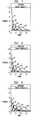
- FIGS. 4-9show optical power as a function of principal mode number, for 0 and 4 ⁇ m beam offset, and for various beam radii;
- FIG. 10schematically shows an exemplary multimode fiber communication system according to this invention.
- FIGS. 1-3 and 10are not intended to be to scale or in proportion.
- the instant inventionis embodied in apparatus for launching a light beam from a laser or other semiconductor light source into a multimode optical fiber such that at least some lower order modes of the multimode optical fiber are substantially not excited, with at least some higher order modes being excited.
- the apparatuscomprises one or more launch-related members selected such that said light beam from the semiconductor light source (e.g., a vertical cavity surface emitting laser or VCSEL) is directed onto an input face of the multimode optical fiber nominally at a center of said input face, such that the light beam forms an angle ⁇ b with a direction normal to said input face, with ⁇ b selected such that at least one of said lower order modes is substantially not excited.
- the semiconductor light sourcee.g., a vertical cavity surface emitting laser or VCSEL
- the instant inventionis also embodied in a method of launching a light beam from a semiconductor light source into a multimode optical fiber such that at least some lower order modes of the multimode optical fiber are substantially not excited, with at least some higher order modes being excited.
- the methodcomprises directing the light beam onto an input face of the multimode fiber, nominally at the center of the input face, such that the light beam forms an angle ⁇ b with a direction normal to the input face, with ⁇ b selected such that at least one lower order mode is substantially not excited. Preferably several (preferably all) lower order modes are substantially not excited.
- the shortcoming of the prior art off-center method of coupling signal radiation into a MMFis overcome by the method of the invention, wherein the signal beam impinges nominally centrally on the input face of the MMF, and at least one of the launch-related elements is angled, such that launch of optical power into at least one lower order mode is substantially avoided.
- the at least one lower order modeincludes the LP 01 fundamental mode.
- “launch-related” componentsare the signal radiation source (typically a semiconductor laser), the MMF, the input face of the MMF, and the optional optical components between the output surface of the radiation source and the input face of the MMF.
- FIGS. 1-3schematically depict apparatus according to the invention.
- FIG. 1shows launch-related components 10 arranged such that the signal radiation beam 13 is tilted by ⁇ b with respect to the center axis of the MMF 11 .
- Numeral 12refers to the input face of the MMF, which in the embodiment of FIG. 1 is at right angle to the axis of the MMF.
- Numerals 14 - 16refer, respectively, to a semiconductor signal radiation source (typically a laser), the center axis of the laser beam, and the output surface of the laser.
- ⁇ bis preferably in the range 2-8°.
- FIG. 2shows a further embodiment, wherein an appropriate optical element 31 (e.g., a lens) serves to deviate the signal beam 13 from the axial direction, such that the input face 12 of the MMF is tilted with respect to the signal radiation beam 13 .
- an appropriate optical element 31e.g., a lens
- the angle ⁇ bpreferably is also in the range 2-8°.
- FIG. 3shows a still further embodiment, wherein the input face 12 of MMF 11 is tilted with respect to the axis of the MMF.
- ⁇ bpreferably is in the range 4-16°.
- the angle ⁇ bis the angle between the axis of the MMF and the direction perpendicular to the input face.
- ⁇ bis the angle between the axis of the MMF and the direction of the input beam 13 ′
- ⁇ bis the angle between the axis of the MMF and the direction of the input beam 13 .
- the input face of the MMFis essentially perpendicular to the axis of the MMF.
- the laser light source 14is in close proximity, exemplary less than 10 mm, to the input face of the multimode fiber, and the signal radiation beam is unguided from the output face of the semiconductor signal radiation source to the input face of the MMF.
- the presence of the angled launch-related component in the signal radiation pathserves to substantially avoid launching of signal power into one or more of the low order modes of the MMF. This works best for laser beams with relatively small divergence (e.g., Gaussian beams), with a beam width greater than the spot sizes of the low-order modes of the MMF.
- relatively small divergencee.g., Gaussian beams
- a conventional MMFhas a core radius of 50 ⁇ m, maximum fractional index difference (n core ⁇ n clad )/n core of 1%, and a profile shape close to parabolic.
- spot size of the fundamental modeis 4 ⁇ m.
- the launch beam widthpreferably is greater than 4 ⁇ m, and the beam has low divergence (e.g., is a Gaussian beam).
- FIGS. 4-9show the power launched into the various modes of the above-described MMF, under a variety of launch conditions, namely, a Gaussian beam of radius 7, 10 and 13 ⁇ m, having offsets of 0 and 4 ⁇ m from the center of the fiber, and with angles from 0 to 0.15 radians.
- the data of FIGS. 5-10were obtained by calculation using the well known scalar wave approximation to Maxwell's equation. A detailed description of the method can be found, for instance, in A. W. Snyder et al., “Optical Waveguide Theory”, Chapman and Hall, London, 1983, chapter 13 .
- the tilt angletypically is in the range 1°-20°.
- FIG. 10schematically depicts an optical fiber communication system 100 according to the invention.
- Numeral 101refers to a transmitter including a semiconductor signal radiation source (exemplarily a VCSEL)
- numeral 102refers to a receiver
- MMF 11signal-transmissively connects transmitter and receiver.
- Input face 12 of the MMFis tilted with respect to the direction of the input laser beam, whereby one or more lower order modes in the MMF are substantially not excited.
Landscapes
- Physics & Mathematics (AREA)
- General Physics & Mathematics (AREA)
- Optics & Photonics (AREA)
- Optical Couplings Of Light Guides (AREA)
- Semiconductor Lasers (AREA)
Abstract
Description
Claims (7)
Priority Applications (1)
| Application Number | Priority Date | Filing Date | Title |
|---|---|---|---|
| US09/608,364US6501884B1 (en) | 2000-06-30 | 2000-06-30 | Article comprising means for mode-selective launch into a multimode optical fiber, and method for a mode-selective launch |
Applications Claiming Priority (1)
| Application Number | Priority Date | Filing Date | Title |
|---|---|---|---|
| US09/608,364US6501884B1 (en) | 2000-06-30 | 2000-06-30 | Article comprising means for mode-selective launch into a multimode optical fiber, and method for a mode-selective launch |
Publications (1)
| Publication Number | Publication Date |
|---|---|
| US6501884B1true US6501884B1 (en) | 2002-12-31 |
Family
ID=24436158
Family Applications (1)
| Application Number | Title | Priority Date | Filing Date |
|---|---|---|---|
| US09/608,364Expired - LifetimeUS6501884B1 (en) | 2000-06-30 | 2000-06-30 | Article comprising means for mode-selective launch into a multimode optical fiber, and method for a mode-selective launch |
Country Status (1)
| Country | Link |
|---|---|
| US (1) | US6501884B1 (en) |
Cited By (14)
| Publication number | Priority date | Publication date | Assignee | Title |
|---|---|---|---|---|
| US20050152643A1 (en)* | 2004-01-12 | 2005-07-14 | Blauvelt Henry A. | Apparatus and methods for launching an optical signal into multimode optical fiber |
| US20050259916A1 (en)* | 2003-05-21 | 2005-11-24 | David Jenkins | Multimode fiber optical fiber transmission system with offset launch single mode long wavelength vertical cavity surface emitting laser transmitter |
| US20070166042A1 (en)* | 2003-12-23 | 2007-07-19 | Seeds Alwyn J | Multiservice optical communication |
| US20070253714A1 (en)* | 2002-12-13 | 2007-11-01 | University College London | Optical Communication System for Wireless Radio Signals |
| US20080124087A1 (en)* | 2004-08-20 | 2008-05-29 | Peter Hartmann | Multimode Fibre Optical Communication System |
| US20080131051A1 (en)* | 2004-05-22 | 2008-06-05 | Ocp-Europe, Ltd. | Multi-mode fiber, optical fiber transmission system with offset-launch, single-mode, long-wavelength, vertical cavity surface emitting laser transmitter |
| US20090123114A1 (en)* | 2007-07-26 | 2009-05-14 | Llghtwire, Inc. | Offset launch mode from nanotaper waveguide into multimode fiber |
| US7576909B2 (en) | 1998-07-16 | 2009-08-18 | Imra America, Inc. | Multimode amplifier for amplifying single mode light |
| US7656578B2 (en) | 1997-03-21 | 2010-02-02 | Imra America, Inc. | Microchip-Yb fiber hybrid optical amplifier for micro-machining and marking |
| US20110075132A1 (en)* | 2009-09-30 | 2011-03-31 | James Scott Sutherland | Angle-cleaved optical fibers and methods of making and using same |
| US20110075976A1 (en)* | 2009-09-30 | 2011-03-31 | James Scott Sutherland | Substrates and grippers for optical fiber alignment with optical element(s) and related methods |
| US20110091181A1 (en)* | 2009-10-15 | 2011-04-21 | Demeritt Jeffery A | Coated Optical Fibers and Related Apparatuses, Links, and Methods for Providing Optical Attenuation |
| US8761211B2 (en) | 1998-11-25 | 2014-06-24 | Imra America, Inc. | Multi-mode fiber amplifier |
| US9620925B2 (en) | 2013-01-31 | 2017-04-11 | Spi Lasers Uk Limited | Fiber optical laser combiner |
Citations (4)
| Publication number | Priority date | Publication date | Assignee | Title |
|---|---|---|---|---|
| US4546249A (en)* | 1983-07-01 | 1985-10-08 | The United States Of America As Represented By The Secretary Of The Navy | High speed optically controlled sampling system |
| US4793679A (en)* | 1987-04-20 | 1988-12-27 | General Electric Company | Optical coupling system |
| US5949932A (en)* | 1992-04-16 | 1999-09-07 | Coherent, Inc. | Assembly for focusing and coupling the radiation produced by a semiconductor laser into optical fibers |
| DE19809823C1 (en) | 1998-02-27 | 1999-09-30 | Siemens Ag | Coupler arrangement for coupling light from transmitter into multimode optical waveguide |
- 2000
- 2000-06-30USUS09/608,364patent/US6501884B1/ennot_activeExpired - Lifetime
Patent Citations (4)
| Publication number | Priority date | Publication date | Assignee | Title |
|---|---|---|---|---|
| US4546249A (en)* | 1983-07-01 | 1985-10-08 | The United States Of America As Represented By The Secretary Of The Navy | High speed optically controlled sampling system |
| US4793679A (en)* | 1987-04-20 | 1988-12-27 | General Electric Company | Optical coupling system |
| US5949932A (en)* | 1992-04-16 | 1999-09-07 | Coherent, Inc. | Assembly for focusing and coupling the radiation produced by a semiconductor laser into optical fibers |
| DE19809823C1 (en) | 1998-02-27 | 1999-09-30 | Siemens Ag | Coupler arrangement for coupling light from transmitter into multimode optical waveguide |
Non-Patent Citations (3)
| Title |
|---|
| Haliiday, Resnick, Walker; Fundamentals of Physics 6th Ed. vol. 2; John Wiley and Sons. Inc.; p. 803.** |
| Raddatz et al., IEEE Photonics Technology Letters, "Influence of Restricted Mode Excitation on Bandwidth of Multimode Fiber Links", vol. 10, No., 4, pp. 534-536, Apr. 1998. |
| Snyder et al., Chapman & Hall Medical "Optical Waveguide Theory", Chapter 13, pp. 281-301. |
Cited By (25)
| Publication number | Priority date | Publication date | Assignee | Title |
|---|---|---|---|---|
| US7656578B2 (en) | 1997-03-21 | 2010-02-02 | Imra America, Inc. | Microchip-Yb fiber hybrid optical amplifier for micro-machining and marking |
| US7576909B2 (en) | 1998-07-16 | 2009-08-18 | Imra America, Inc. | Multimode amplifier for amplifying single mode light |
| US9595802B2 (en) | 1998-11-25 | 2017-03-14 | Imra America, Inc. | Multi-mode fiber amplifier |
| US9570880B2 (en) | 1998-11-25 | 2017-02-14 | Imra America, Inc. | Multi-mode fiber amplifier |
| US9450371B2 (en) | 1998-11-25 | 2016-09-20 | Imra America, Inc. | Mode-locked multi-mode fiber laser pulse source |
| US9153929B2 (en) | 1998-11-25 | 2015-10-06 | Imra America, Inc. | Mode-locked multi-mode fiber laser pulse source |
| US8761211B2 (en) | 1998-11-25 | 2014-06-24 | Imra America, Inc. | Multi-mode fiber amplifier |
| US20070253714A1 (en)* | 2002-12-13 | 2007-11-01 | University College London | Optical Communication System for Wireless Radio Signals |
| US20050259916A1 (en)* | 2003-05-21 | 2005-11-24 | David Jenkins | Multimode fiber optical fiber transmission system with offset launch single mode long wavelength vertical cavity surface emitting laser transmitter |
| US7231114B2 (en) | 2003-05-21 | 2007-06-12 | Ocp-Europe, Ltd. | Multimode fiber optical fiber transmission system with offset launch single mode long wavelength vertical cavity surface emitting laser transmitter |
| US20070166042A1 (en)* | 2003-12-23 | 2007-07-19 | Seeds Alwyn J | Multiservice optical communication |
| US20050152643A1 (en)* | 2004-01-12 | 2005-07-14 | Blauvelt Henry A. | Apparatus and methods for launching an optical signal into multimode optical fiber |
| WO2005067573A3 (en)* | 2004-01-12 | 2006-10-05 | Xponent Photonics Inc | Apparatus and methods for launching an optical signal into multimode optical fiber |
| US7228032B2 (en)* | 2004-01-12 | 2007-06-05 | Xponent Photonics Inc. | Apparatus and methods for launching an optical signal into multimode optical fiber |
| US7477815B2 (en) | 2004-05-22 | 2009-01-13 | Ocp-Europe, Ltd | Multi-mode fiber, optical fiber transmission system with offset-launch, single-mode, long-wavelength, vertical cavity surface emitting laser transmitter |
| US20080131051A1 (en)* | 2004-05-22 | 2008-06-05 | Ocp-Europe, Ltd. | Multi-mode fiber, optical fiber transmission system with offset-launch, single-mode, long-wavelength, vertical cavity surface emitting laser transmitter |
| US20080124087A1 (en)* | 2004-08-20 | 2008-05-29 | Peter Hartmann | Multimode Fibre Optical Communication System |
| US7706644B2 (en) | 2007-07-26 | 2010-04-27 | Lightwire, Inc. | Offset launch mode from nanotaper waveguide into multimode fiber |
| US20090123114A1 (en)* | 2007-07-26 | 2009-05-14 | Llghtwire, Inc. | Offset launch mode from nanotaper waveguide into multimode fiber |
| US20110075976A1 (en)* | 2009-09-30 | 2011-03-31 | James Scott Sutherland | Substrates and grippers for optical fiber alignment with optical element(s) and related methods |
| US8477298B2 (en) | 2009-09-30 | 2013-07-02 | Corning Incorporated | Angle-cleaved optical fibers and methods of making and using same |
| US20110075132A1 (en)* | 2009-09-30 | 2011-03-31 | James Scott Sutherland | Angle-cleaved optical fibers and methods of making and using same |
| US8295671B2 (en) | 2009-10-15 | 2012-10-23 | Corning Incorporated | Coated optical fibers and related apparatuses, links, and methods for providing optical attenuation |
| US20110091181A1 (en)* | 2009-10-15 | 2011-04-21 | Demeritt Jeffery A | Coated Optical Fibers and Related Apparatuses, Links, and Methods for Providing Optical Attenuation |
| US9620925B2 (en) | 2013-01-31 | 2017-04-11 | Spi Lasers Uk Limited | Fiber optical laser combiner |
Similar Documents
| Publication | Publication Date | Title |
|---|---|---|
| RU2142152C1 (en) | Connector for non-coaxial transmission of light energy | |
| US6501884B1 (en) | Article comprising means for mode-selective launch into a multimode optical fiber, and method for a mode-selective launch | |
| US6349159B1 (en) | Lenses that launch high bandwidth modes into a fiber optic cable while eliminating feedback to a laser | |
| US6546169B1 (en) | Pump couplers for double-clad fiber devices | |
| CN102598545B (en) | For through improveing the optical fiber end structure of multimode bandwidth and related system and method | |
| US6014483A (en) | Method of fabricating a collective optical coupling device and device obtained by such a method | |
| US4807954A (en) | Optical coupling device | |
| US8503840B2 (en) | Optical-fiber array method and apparatus | |
| US5757993A (en) | Method and optical system for passing light between an optical fiber and grin lens | |
| US6816652B1 (en) | Pump fiber bundle coupler for double-clad fiber devices | |
| US9625653B2 (en) | Universal fiber optic connector | |
| US6477301B1 (en) | Micro-optic coupler incorporating a tapered fiber | |
| CN111665594A (en) | Optical connection structure | |
| CN109828335A (en) | A kind of optical coupled module and electronic equipment | |
| CN106461895A (en) | System and apparatus for free space optical coupling | |
| JP2002148471A (en) | Article comprising multi-mode optical fiber coupler | |
| US20040208440A1 (en) | Optical collimator structure | |
| US6707832B2 (en) | Fiber coupling enhancement via external feedback | |
| US6801722B1 (en) | Optical tracking system with reflective fiber | |
| JP2002236239A (en) | Optical fiber, optical module, optical fiber device | |
| JPH0815564A (en) | Optical fiber connecting system and its connecting module | |
| US10302883B2 (en) | Optical coupling assemblies | |
| US6748139B2 (en) | Coupler utilizing a diffractive optical element for coupling light to an optical waveguide | |
| JPH07281054A (en) | Fiber optic terminal | |
| JP2000338359A (en) | Optical monitor module |
Legal Events
| Date | Code | Title | Description |
|---|---|---|---|
| AS | Assignment | Owner name:LUCENT TECHNOLOGIES INC., NEW JERSEY Free format text:ASSIGNMENT OF ASSIGNORS INTEREST;ASSIGNORS:GOLOWICH, STEVEN EUGENE;REED, WILLIAM ALFRED;REEL/FRAME:010945/0326;SIGNING DATES FROM 20000627 TO 20000629 | |
| STCF | Information on status: patent grant | Free format text:PATENTED CASE | |
| FPAY | Fee payment | Year of fee payment:4 | |
| FEPP | Fee payment procedure | Free format text:PAYOR NUMBER ASSIGNED (ORIGINAL EVENT CODE: ASPN); ENTITY STATUS OF PATENT OWNER: LARGE ENTITY | |
| FPAY | Fee payment | Year of fee payment:8 | |
| FPAY | Fee payment | Year of fee payment:12 | |
| AS | Assignment | Owner name:OMEGA CREDIT OPPORTUNITIES MASTER FUND, LP, NEW YORK Free format text:SECURITY INTEREST;ASSIGNOR:WSOU INVESTMENTS, LLC;REEL/FRAME:043966/0574 Effective date:20170822 Owner name:OMEGA CREDIT OPPORTUNITIES MASTER FUND, LP, NEW YO Free format text:SECURITY INTEREST;ASSIGNOR:WSOU INVESTMENTS, LLC;REEL/FRAME:043966/0574 Effective date:20170822 | |
| AS | Assignment | Owner name:WSOU INVESTMENTS, LLC, CALIFORNIA Free format text:ASSIGNMENT OF ASSIGNORS INTEREST;ASSIGNOR:ALCATEL LUCENT;REEL/FRAME:044000/0053 Effective date:20170722 | |
| AS | Assignment | Owner name:BP FUNDING TRUST, SERIES SPL-VI, NEW YORK Free format text:SECURITY INTEREST;ASSIGNOR:WSOU INVESTMENTS, LLC;REEL/FRAME:049235/0068 Effective date:20190516 | |
| AS | Assignment | Owner name:WSOU INVESTMENTS, LLC, CALIFORNIA Free format text:RELEASE BY SECURED PARTY;ASSIGNOR:OCO OPPORTUNITIES MASTER FUND, L.P. (F/K/A OMEGA CREDIT OPPORTUNITIES MASTER FUND LP;REEL/FRAME:049246/0405 Effective date:20190516 | |
| AS | Assignment | Owner name:OT WSOU TERRIER HOLDINGS, LLC, CALIFORNIA Free format text:SECURITY INTEREST;ASSIGNOR:WSOU INVESTMENTS, LLC;REEL/FRAME:056990/0081 Effective date:20210528 | |
| AS | Assignment | Owner name:WSOU INVESTMENTS, LLC, CALIFORNIA Free format text:RELEASE BY SECURED PARTY;ASSIGNOR:TERRIER SSC, LLC;REEL/FRAME:056526/0093 Effective date:20210528 |