US6500181B1 - Instrument for folding and inserting anterior chamber intraocular lenses - Google Patents
Instrument for folding and inserting anterior chamber intraocular lensesDownload PDFInfo
- Publication number
- US6500181B1 US6500181B1US09/690,783US69078300AUS6500181B1US 6500181 B1US6500181 B1US 6500181B1US 69078300 AUS69078300 AUS 69078300AUS 6500181 B1US6500181 B1US 6500181B1
- Authority
- US
- United States
- Prior art keywords
- iol
- tube
- instrument
- double
- folding
- Prior art date
- Legal status (The legal status is an assumption and is not a legal conclusion. Google has not performed a legal analysis and makes no representation as to the accuracy of the status listed.)
- Expired - Fee Related
Links
- 210000002159anterior chamberAnatomy0.000titleclaimsabstractdescription21
- 238000003780insertionMethods0.000claimsabstractdescription150
- 230000037431insertionEffects0.000claimsabstractdescription150
- 229920001296polysiloxanePolymers0.000claimsdescription4
- NIXOWILDQLNWCW-UHFFFAOYSA-Nacrylic acid groupChemical groupC(C=C)(=O)ONIXOWILDQLNWCW-UHFFFAOYSA-N0.000claimsdescription3
- 239000000463materialSubstances0.000claimsdescription3
- 210000000695crystalline lenAnatomy0.000description32
- 238000000034methodMethods0.000description9
- 208000002177CataractDiseases0.000description7
- 210000004087corneaAnatomy0.000description7
- 206010002945AphakiaDiseases0.000description6
- 238000011144upstream manufacturingMethods0.000description6
- 230000004438eyesightEffects0.000description5
- 230000008569processEffects0.000description5
- 230000003287optical effectEffects0.000description4
- 230000018109developmental processEffects0.000description3
- 208000014674injuryDiseases0.000description3
- 229920003229poly(methyl methacrylate)Polymers0.000description3
- 239000004926polymethyl methacrylateSubstances0.000description3
- 230000032683agingEffects0.000description2
- 238000005452bendingMethods0.000description2
- 230000004071biological effectEffects0.000description2
- 201000010099diseaseDiseases0.000description2
- 208000037265diseases, disorders, signs and symptomsDiseases0.000description2
- 238000000605extractionMethods0.000description2
- 230000001771impaired effectEffects0.000description2
- 239000007943implantSubstances0.000description2
- 230000003993interactionEffects0.000description2
- 238000003825pressingMethods0.000description2
- 230000008733traumaEffects0.000description2
- 206010020675HypermetropiaDiseases0.000description1
- 208000022873Ocular diseaseDiseases0.000description1
- BQCADISMDOOEFD-UHFFFAOYSA-NSilverChemical compound[Ag]BQCADISMDOOEFD-UHFFFAOYSA-N0.000description1
- 208000002847Surgical WoundDiseases0.000description1
- 208000027418Wounds and injuryDiseases0.000description1
- 201000009310astigmatismDiseases0.000description1
- 230000008901benefitEffects0.000description1
- 239000000560biocompatible materialSubstances0.000description1
- 230000015572biosynthetic processEffects0.000description1
- 238000005219brazingMethods0.000description1
- 230000008859changeEffects0.000description1
- 230000006378damageEffects0.000description1
- 230000002950deficientEffects0.000description1
- 230000003412degenerative effectEffects0.000description1
- 206010012601diabetes mellitusDiseases0.000description1
- 230000000694effectsEffects0.000description1
- 210000002889endothelial cellAnatomy0.000description1
- 230000003511endothelial effectEffects0.000description1
- 201000006318hyperopiaDiseases0.000description1
- 230000004305hyperopiaEffects0.000description1
- 208000015181infectious diseaseDiseases0.000description1
- 238000009434installationMethods0.000description1
- 230000007774longtermEffects0.000description1
- 239000000314lubricantSubstances0.000description1
- 230000003278mimic effectEffects0.000description1
- 208000001491myopiaDiseases0.000description1
- 230000004379myopiaEffects0.000description1
- 239000004033plasticSubstances0.000description1
- 229920003023plasticPolymers0.000description1
- 201000010041presbyopiaDiseases0.000description1
- 238000011084recoveryMethods0.000description1
- 210000001525retinaAnatomy0.000description1
- 238000000926separation methodMethods0.000description1
- 229910052709silverInorganic materials0.000description1
- 239000004332silverSubstances0.000description1
- 238000005476solderingMethods0.000description1
- 229910001220stainless steelInorganic materials0.000description1
- 239000010935stainless steelSubstances0.000description1
- 230000003068static effectEffects0.000description1
- 150000003431steroidsChemical class0.000description1
- 230000009885systemic effectEffects0.000description1
- 238000002560therapeutic procedureMethods0.000description1
- 239000008154viscoelastic solutionSubstances0.000description1
Images


Classifications
- A—HUMAN NECESSITIES
- A61—MEDICAL OR VETERINARY SCIENCE; HYGIENE
- A61F—FILTERS IMPLANTABLE INTO BLOOD VESSELS; PROSTHESES; DEVICES PROVIDING PATENCY TO, OR PREVENTING COLLAPSING OF, TUBULAR STRUCTURES OF THE BODY, e.g. STENTS; ORTHOPAEDIC, NURSING OR CONTRACEPTIVE DEVICES; FOMENTATION; TREATMENT OR PROTECTION OF EYES OR EARS; BANDAGES, DRESSINGS OR ABSORBENT PADS; FIRST-AID KITS
- A61F2/00—Filters implantable into blood vessels; Prostheses, i.e. artificial substitutes or replacements for parts of the body; Appliances for connecting them with the body; Devices providing patency to, or preventing collapsing of, tubular structures of the body, e.g. stents
- A61F2/02—Prostheses implantable into the body
- A61F2/14—Eye parts, e.g. lenses or corneal implants; Artificial eyes
- A61F2/16—Intraocular lenses
- A61F2/1662—Instruments for inserting intraocular lenses into the eye
- A—HUMAN NECESSITIES
- A61—MEDICAL OR VETERINARY SCIENCE; HYGIENE
- A61F—FILTERS IMPLANTABLE INTO BLOOD VESSELS; PROSTHESES; DEVICES PROVIDING PATENCY TO, OR PREVENTING COLLAPSING OF, TUBULAR STRUCTURES OF THE BODY, e.g. STENTS; ORTHOPAEDIC, NURSING OR CONTRACEPTIVE DEVICES; FOMENTATION; TREATMENT OR PROTECTION OF EYES OR EARS; BANDAGES, DRESSINGS OR ABSORBENT PADS; FIRST-AID KITS
- A61F2/00—Filters implantable into blood vessels; Prostheses, i.e. artificial substitutes or replacements for parts of the body; Appliances for connecting them with the body; Devices providing patency to, or preventing collapsing of, tubular structures of the body, e.g. stents
- A61F2/02—Prostheses implantable into the body
- A61F2/14—Eye parts, e.g. lenses or corneal implants; Artificial eyes
- A61F2/16—Intraocular lenses
- A61F2/1602—Corrective lenses for use in addition to the natural lenses of the eyes or for pseudo-phakic eyes
- A61F2/1605—Anterior chamber lenses for use in addition to the natural lenses of the eyes, e.g. iris fixated, iris floating
Definitions
- the present inventionrelates generally to the field of ophthalmic, more particularly to intraocular lenses (IOLs), and still more particularly to instruments for implanting IOLs in patient's eyes.
- IOLsintraocular lenses
- phakicwhich refers an eye in which the natural ocular lens is still present, may be helpful to the understanding of the present invention.
- the term “phakic”is in contrast to the term “aphakic” which refers to an eye from which the natural ocular lens has been removed.
- a phakic eyeis considered a dynamic or active eye because the existing natural lens is a living part of an eye, and is therefore subject to change over time due to such biological effects as disease or aging.
- An aphakic eyeis considered a static eye because the natural lens has been removed and thus is no longer subject to biological effects that would otherwise affect the natural lens.
- Vision in a phakic eyeis caused by light from a viewed object being refracted by the cornea and the natural lens located rearward of the cornea to form an image on the retina at the back of the eye.
- image formationmay, for example, be assisted by corrective spectacles, contact lens or corneal reshaping.
- CataractA common ocular problem in a phakic eye is impaired vision due to the natural lens becoming cloudy or opaque—a degenerative condition known as “cataract.” Cataracts typically form with aging, with most individuals over about 60 years old suffering from cataracts to at least some extent. Cataracts can, however, also occur as a result of trauma, systemic diseases (such as diabetes), ocular diseases, long term steroid therapy, excessive exposure to ultra violet light, and heredity.
- cataractscannot be cured, reduced, or even significantly arrested. Corrective treatment for cataracts therefore requires the surgical extraction of the natural lens when the lens becomes so cloudy that vision in the afflicted eye becomes so impaired as to affect the patient's life style. In this manner a phakic eye becomes an aphakic eye.
- IOLintraocular lens
- Typical IOLsare constructed having an transparent optic with attached fixation members for maintaining the optical axis of the optic aligned with the optical axis of the eye.
- IOLswere typically constructed from a rigid, biocompatible polymethyl methacrylate (PMMA) plastic material.
- PMMApolymethyl methacrylate
- IOLsare implanted in the posterior chamber of the eye (i.e., the “bag”) from which the natural lens has been removed in order to mimic the natural lens as much as possible.
- corrective IOLs for phakic eyesare desirably implanted in the anterior chamber of the eyes (between the cornea and the iris) because the posterior chamber is still occupied by the natural lens.
- Elastically deformable anterior chamber IOLsto which this present invention indirectly relates, are similar in many respects to current elastically deformable posterior chamber IOLs.
- anterior chamber IOLsare usually much more difficult to implant.
- a significant anterior chamber IOL implanting problemrelates to the unfolding of elastically deformed IOLs from known IOL inserters into the anterior chamber of the eye, in which the typical axial separation between the cornea and natural crystalline lens is only about 2 mm.
- Typical known IOL inserterssingle fold elastically deformable IOLs in half across the optic, creating what is commonly referred to as a “taco” fold.
- a “taco” folded IOLrequires a space (along the optical axis) equal to one-half the diameter of the optic for the IOL to unfold into.
- a “taco” folded IOL having a typical optic diameter of 6 mmrequires a 3 mm axial space for unfolding. It is thus inevitable that the unfolding of a single folded elastically deformable IOL in the anterior chamber will cause unintentional contact with, and likely injury to, the sensitive posterior endothelial surface of the cornea and/or the anterior surface of the crystalline lens.
- a principal objective of the present inventionis, thus to provide an IOL insertion instrument that double folds an elastically deformable anterior chamber IOL so that the IOL requires substantially less axial unfolding space in the anterior chamber than does a single folded IOL. Because the double folded IOL having a 6 mm diameter optic requires only about 1.5 mm of anterior chamber axial unfolding space, the possibility of the unfolding optic unintentionally contacting and injuring the endothelial cell surface of the cornea and/or the anterior surface of the crystalline lens is minimized.
- an instrument for double folding an elastically deformable intraocular lens (IOL) and for inserting said double folded IOL into the anterior chamber of a patient's eye for controlled unfoldingcomprises an elongate, slender IOL insertion tube having a distal end and a longitudinal axis, an IOL receiving station located in the tube adjacent a cutaway opening in the tube, and a support element configured for holding a central optic region of an IOL received in the IOL receiving station against an inner surface of the tube during double folding of the IOL.
- an IOL double folding memberinstalled on the tube, the folding member having a converging recess facing the IOL receiving station, the recess being along the tube longitudinal axis and having an IOL discharge opening facing the IOL insertion tube distal end.
- Meansare included for causing relative axial movement between an IOL received in the IOL receiving station and the IOL double folding member to cause the double folding of the IOL into a general C-shape.
- a pistonis axially slidably disposed in the tube for axially pushing the double folded IOL through the distal end of the tube.
- a disposal IOL insertion tipsized for insertion through an ocular incision no greater than about 3.2 mm, is preferably detachably attached to a distal end of the IOL insertion tube, the insertion tip being flexible and constructed of a silicone or an acrylic material.
- the insertion tiphas an oval cross section having an external width between about two times and three times greater than an external height of the tip.
- the distal end of the IOL insertion tipis beveled at an angle between about 30 degrees and about 45 degrees to permit gradual and controlled unfolding of the IOL after insertion into an eye.
- the IOL folding memberis axially movable on said tube and the means for causing relative axial movement between the IOL and the IOL folding member is connected for causing the IOL folding member to move axially along the IOL insertion tube so that the converging recess moves onto the IOL received in the IOL receiving station member, thereby causing the double folding of the IOL received in received IOL receiving station.
- the means for causing relative movementincludes a drive member threadably connected to the tube and in driving engagement with the IOL folding member for causing axial movement thereof.
- the support elementincludes an IOL support member movable between a first position in which the support element permits the insertion of an IOL into the IOL receiving station through the tube cutaway opening and a second position in which the support element holds a central optic region of the IOL against the tube inner surface parallel to said tube longitudinal axis.
- Means cooperating with the IOL folding membermay be provided for exerting a side pressure on the IOL after being double folded in a general C-shape to thereby compress the double folded IOL into a tighter C-shape.
- the IOL double folding memberis fixed to the IOL insertion tube and the means for causing relative axial movement between an IOL received in the IOL receiving station and the double folding member causes the IOL received in the IOL receiving station to be moved axially through the IOL insertion tube into the converging recess of the IOL double folding member.
- the means for causing relative axial movementcomprises a piston axially slidably disposed in the tube, a distal end of the piston being configured for engaging an edge of an optic portion of an IOL received in the receiving station.
- the support elementcomprises a slender, axial projection at the piston distal end.
- the instrument for double folding an elastically deformable intraocular lens (IOL) and for inserting the double folded IOL into the anterior chamber of a patient's eye for controlled unfoldingcomprises an elongate, slender IOL insertion tube having a distal end and a longitudinal axis and an IOL receiving and folding station located inside the tube adjacent a side opening in the tube.
- the IOL receiving and folding stationis configured for receiving an IOL which has an optic and haptics attached to opposing edges of the optic, with the haptics generally aligned with the IOL insertion tube longitudinal axis.
- an IOL double folding memberaxially movably mounted on the IOL insertion tube, the IOL double folding member having a converging recess facing the IOL receiving and folding station and an IOL discharge opening facing the distal end of the tube, the recess being along the longitudinal axis of the tube.
- a driveris threadably installed on an externally threaded element fixed to the IOL insertion tube and is coupled to the IOL double folding member for causing movement of IOL double folding member axially along the IOL insertion tube between a first axial position in which the member is out of engagement with an IOL received in the IOL receiving and folding station and a second axial position in which the member causes the double folding of an IOL received in the station into a general C-shape.
- the means for axially moving said IOL folding member between said folding member first and second positionsincludes an externally threaded member fixed to said IOL insertion tube, said driver being threadably installed on said externally threaded element.
- Meansare included for axially pushing a double folded IOL positioned in the IOL receiving and folding station through the IOL double folding member discharge opening and the distal end of the tube.
- An IOL support member having an IOL support elementis movable between a first position in which the support element permits the insertion of an IOL into the IOL receiving and folding station through the tube cutaway opening and a second position in which the support element holds a central optic region of the IOL against an inner surface of the tube parallel to the tube longitudinal axis as the IOL is double folded.
- means cooperating with the IOL folding memberare included for exerting a side pressure on the IOL after being double folded into a general C-shape to thereby compress the double folded IOL into a tighter C-shape.
- a disposable IOL insertion tip and means for detachably attaching the insertion tip to the IOL insertion tube distal endhas an oval transverse cross sectional shape with an external width that is about 2 to about 3 times greater than an external height, a wide region of the insertion tip being thereby formed; the insertion tip being sized for insertion through an ocular incision no greater than about 3.2 mm.
- the wide region of the IOL insertion tube distal endis preferably beveled at an angle between about 30 and about 45 degrees
- a variation instrument for double folding an elastically deformable intraocular lens (IOL) and for inserting said double folded IOL into the anterior chamber of a patient's eye for controlled unfoldingcomprises an elongate, slender IOL insertion tube having a distal end and a longitudinal axis, and IOL receiving station located inside the tube adjacent a side opening in the tube.
- the IOL receiving stationis configured for receiving an IOL, which has an optic and haptics attached to opposing edges of the optic, with the haptics generally aligned with the IOL insertion tube longitudinal axis.
- an IOL double folding memberfixed to the IOL insertion tube and having a converging IOL engaging recess with a wide opening facing the IOL receiving station and a discharge opening facing the distal end of the IOL insertion tube, the recess being along the tube longitudinal axis.
- a support memberconfigured for holding a central optic region of an IOL received in the IOL receiving station against an inner surface of said IOL insertion tube along a line parallel to the insertion tube longitudinal axis.
- a pistonis installed in the IOL insertion tube for axially pushing the IOL received in the IOL receiving station along the tube and into the IOL double folding member converging recess for causing the double folding of the IOL into a general C-shape, and for thereafter pushing the double folded IOL through the distal end of the tube.
- the support memberis formed as an axial projection at the distal end of the piston.
- a disposable IOL insertion tip and means for detachably attaching the insertion tip to the IOL insertion tube distalthe insertion tip having an oval transverse cross sectional shape with an external width that is about 2 to about 3 times greater than an external height, a wide region of the insertion tip being thereby formed, and being sized for insertion through an ocular incision no greater than about 3.2 mm.
- the wide region of the IOL insertion tube distal endis beveled at an angle between about 30 and about 45 degrees.
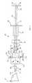
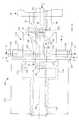
- FIG. 1is a plan view of the anterior chamber intraocular lens (IOL) folding and inserting instrument of the present invention, showing an IOL insertion tube, an IOL receiving and folding station on the insertion tube containing a representative IOL, an axially movable IOL double folding member, a barrel attached to the IOL insertion tube and an IOL insertion piston disposed in the barrel and IOL insertion tube;
- IOLanterior chamber intraocular lens
- FIG. 2is a partial, enlarged plan view of the instrument of FIG. 1, showing an IOL received in the IOL receiving and folding region of the IOL insertion tube and showing the axially movable IOL double folding member positioned away from the IOL receiving and folding station;
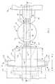
- FIG. 3is a longitudinal cross sectional drawing looking along line 3 — 3 of FIG. 2, showing the IOL received into the IOL receiving and folding region and showing IOL double folding means and IOL holding means and showing a n IOL holding member finger positioned for holding the received IOL against an inner wall surface of the IOL insertion tube;
- FIG. 4is a vertical cross sectional drawing looking along line 4 — 4 of FIG. 3, showing the IOL holding member in a vertical sliding relationship with the IOL insertion tube;
- FIG. 5is a vertical cross sectional drawing looking along line 5 — 5 of FIG. 3, showing the IOL held in the IOL holding and folding station and showing a transverse IOL compressing member associated with the IOL double folding member;
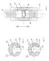
- FIG. 6is a vertical cross sectional drawing looking along line 6 — 6 of FIG. 3 showing the shape of the converging internal recess in the IOL double folding member adjacent the opening of the recess;
- FIG. 7is a vertical cross sectional drawing looking along line 7 — 7 of FIG. 3 showing the shape of the converging internal recess in the IOL double folding member further from the opening of the recess;
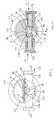
- FIG. 8is a partial, enlarged plan view of the instrument, similar to FIG. 2, showing the IOL double folding member axially moved into initial folding engagement with the IOL received in the IOL receiving and folding station and showing partial folding of the IOL;
- FIG. 9is a transverse cross sectional drawing, similar to FIG. 6, looking along line 9 — 9 of FIG. 8 showing the initial folding stage of the IOL held in the IOL holding and folding station;
- FIG. 10is a partial, enlarged plan view of the instrument, similar to FIG. 8, showing the IOL double folding member axially moved into substantially complete engagement with the IOL received in the IOL receiving and folding station and showing substantially complete double folding of the IOL;
- FIG. 11is a transverse cross sectional drawing, similar to FIGS. 6 and 9, looking along line 11 — 11 of FIG. 10 showing the double folding of the IOL held in the IOL holding and folding station and showing the transverse IOL compressing member associated with the IOL double folding member actuated to transversely compress the double folded IOL;
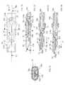
- FIG. 12is a plan view of a distal end region of the IOL insertion tube, showing in broken lines the double folded IOL just upstream of an exit end of the tube;
- FIG. 13is a transverse cross sectional drawing looking along line 13 — 13 of FIG. 12, showing the flattened-oval cross sectional shape of the IOL insertion tube and showing the double folded IOL curled inside the tube;
- FIG. 14is a longitudinal cross sectional drawing looking along line 14 — 14 of FIG. 12, showing the double folded IOL pushed in the direction of Arrow “A′” by a piston disposed in the tube so that the double folded IOL is axially positioned just upstream of an angled opening at the distal end of the IOL insertion tube;
- FIG. 15is a longitudinal cross sectional drawing similar to FIG. 14, showing the double folded IOL pushed by the piston further in the direction of Arrow “A′” so that the leading haptic and the leading edge of the optic portion of the double folded IOL are pushed axially out of the angled opening at the distal end of the IOL insertion tube;
- FIG. 16is a longitudinal cross sectional drawing similar to FIG. 15, showing the double folded IOL pushed by the piston still further in the direction of Arrow “A′” so that major portions of the IOL are pushed axially out of the angled opening at the distal end of the IOL insertion tube, and showing the double folded starting to unfold back to its original, unfolded state;
- FIG. 17is a longitudinal cross sectional drawing of a variation IOL double folding instrument, generally corresponding to FIG. 3, showing an unfolded IOL received in an IOL receiving station in an IOL insertion tube, showing a central region of the received IOL held against an inner wall surface of the IOL insertion tube by a slender, axially extending rigid finger at a distal end of an IOL pushing piston disposed in the tube, and further showing an IOL double folding member fixed to the tube downstream of the IOL receiving station;
- FIG. 18is a transverse cross sectional drawing, corresponding generally to FIG. 4, looking along line 18 — 18 of FIG. 17, showing the unfolded IOL held in the IOL holding and folding station by the axially extending rigid finger of the IOL pushing piston;
- FIG. 19is a transverse cross sectional drawing looking along line 19 — 19 of FIG. 17 showing the shape of the converging internal recess in the IOL double folding member;
- FIG. 20is a plan view, corresponding generally to FIG. 13, of a distal end region of the IOL insertion tube, showing in broken lines the double folded IOL supported by the axially extending rigid finger of the IOL pushing piston just upstream of an exit end of the tube;
- FIG. 21is a transverse cross sectional drawing, corresponding generally to FIG. 13, looking along line 21 — 21 of FIG. 20, showing the oval cross sectional shape of the IOL insertion tube and showing the double folded IOL supported by the axially extending rigid finger of the IOL pushing piston and curled inside the tube;
- FIG. 22is drawing corresponding generally to FIG. 14 and is a longitudinal cross sectional drawing looking along line 22 — 22 of FIG. 20, showing the double folded IOL supported by the axially extending rigid finger of the IOL pushing piston with the double folded IOL pushed in the direction of Arrow “A′” by the piston so that the double folded IOL is axially positioned just upstream of an angled opening at the distal end of the IOL insertion tube;
- FIG. 23is a longitudinal cross sectional drawing similar to FIG. 22 and corresponding generally to FIG. 15, showing the double folded IOL still supported by the axially extending rigid finger of the IOL pushing piston, with the double folded IOL pushed by the piston further in the direction of Arrow “A′” so that the leading haptic and the leading edge of the optic portion of the double folded IOL are pushed axially out of the angled opening at the distal end of the IOL insertion tube; and
- FIG. 24is a longitudinal cross sectional drawing similar to FIG. 23 and corresponding generally to FIG. 16, showing major portions of the double folded IOL still supported by the axially extending rigid finger of the IOL pushing piston, with the IOL pushed by the piston still further in the direction of Arrow “A′” so that major portions of the IOL are pushed axially out of the angled opening at the distal end of the IOL insertion tube, and showing the double folded starting to unfold back to its original, unfolded state.
- FIG. 1An intraocular lens (IOL) folding and inserting or implanting instrument 30 , in accordance with the present invention and particularly for implanting an elastically deformable IOL 32 in the anterior chamber of a patient's eye 34 , is shown in FIG. 1 .
- IOLintraocular lens
- instrument 30comprises an elongate, slender IOL insertion tube 36 having an oval transverse cross section and a longitudinal axis 38 .
- IOL insertion tube 36Located within IOL insertion tube 36 is an IOL receiving (holding) and folding station 40 in which is shown representative anterior chamber IOL 32 , for example, the type of IOL disclosed in my co-pending application Ser. No. 09/312,566 now U.S. Pat. No. 6,152,959.
- IOL double folding means 42is installed on IOL insertion tube 36 just downstream of IOL receiving and folding station 40 and IOL retaining means 44 is installed on the insertion tube just upstream of the IOL receiving and folding station.
- insertion tube 36Shown connected to insertion tube 36 at a proximal end region of the tube is a larger diameter barrel 48 having a finger retaining flange 50 at a proximal end 52 of the barrel. As depicted, insertion tube 36 may extend entirely through barrel 48 . Axially disposed in barrel 48 and IOL insertion tube 36 , and projecting from barrel proximal end 52 , is an elongate, slender, rigid IOL pushing piston or plunger 54 formed having a thumb-operating flange 56 at a proximal end 58 of the piston.
- a disposable IOL insertion tube tip 64preferably constructed of a biocompatible material such as silicone, is detachably attached to a distal end 66 of insertion tube 36 , the tube being preferably constructed from stainless steel, so as to be reusable.
- a connection 68 of tip 64 to tube distal end 66may, for example, comprise a conventional luer fitting.
- IOL 32which forms no part of the present invention, IOL receiving and holding station 40 and parts of IOL double folding means 42 , IOL holding means 44 and IOL insertion tube 36 of are shown in more detail in FIG. 2 .
- IOL 32comprises a generally circular optic 70 to which is attached an opposing pair of ocular attachment or fixation elements 72 , commonly called “haptics.”
- hapticsocular attachment or fixation elements
- IOL 32is shown installed in IOL receiving and folding station 40 , which comprises a narrow axial upper wall region 74 of IOL insertion tube 36 with adjacent regions of the tube cut away sufficiently to enable installation of the IOL into the station.
- IOL 32is correctly installed in station 40 , a center 76 of IOL optic 70 and looped ends 80 of haptics 72 are aligned with tube longitudinal axis 38 .
- IOL holding means 44comprises an IOL holding member 82 that is slidably installed in a guide 84 , both of which extend around IOL insertion tube 36 upstream of IOL receiving and holding station 40 .
- IOL Holding member 82is formed having an elongate central slot 85 that permits the holding member to slide up and down with respect to IOL insertion tube 36 .
- IOL Holding member 82is constructed having an elongate, upward curving arm 86 that extends axially toward IOL double folding means 42 (FIG. 3 ). Holding member arm 86 terminates in a narrow, slender finger region 88 sized to fit upwardly into IOL insertion tube 36 through a tube opening or cutaway region 90 at IOL receiving and folding station 40 .
- IOL holding member 82is vertically slidable in guide 84 (for the instrument orientation shown in FIG. 3) in the direction of Arrows B-B′ between a first, retracted position, shown in phantom lines and a second, advanced position, shown in solid lines.
- finger region 88In the first, retracted position of IOL holding member 82 , finger region 88 is located below and clear of IOL receiving and holding station 40 a distance sufficient to permit the loading of IOL 32 into the station. In the second, extended position of IOL holding member 82 , finger region 88 extends upwardly into tube opening 90 and station 40 until an upper surface 92 of the finger region bears against a lower surface 94 of IOL optic 70 along tube longitudinal axis 38 . In this position, finger region 88 presses an upper surface 96 of the optic against an inner surface 98 of tube wall region 74 (see also FIG. 5 ), thereby holding received IOL 32 securely in place in station 40 during the IOL double folding procedure described below.
- IOL double folding means 42comprises three parts: An externally threaded screw element 110 , an internally threaded drive element or nut 112 and an IOL double folding member 114 .
- Externally threaded element 110is fixed (for example, by brazing or silver soldering processes) to IOL insertion tube 36 in a location downstream of IOL receiving and holding station 40 .
- Internally threaded drive element 112is threaded onto externally threaded element 110 and is free to rotate thereon in either rotational direction C-C′ to cause axial movement in the direction of Arrow A-A′.
- IOL double folding member 114is axially slidably mounted on IOL insertion tube 36 , but is constrained against rotation by the cross sectional shape of the tube.
- Drive element 112is connected in axially driving relationship to IOL double folding member 114 by a plurality of lugs 116 (two lugs being shown) that are constrained in an annular groove or recess 118 formed around a distal end region of the double folding member. Consequently, rotation of drive element 112 on externally treaded element 110 imparts an axial sliding movement of IOL double folding member 114 along tube 36 .
- Recess opening 122has a width, w, of about 8 mm and recess 120 has a depth, d, of about 8 mm.
- recess 120is defined by a inner surface 126 into a generally key-hole shape having a an upper, generally elliptically-shaped region 128 and a lower opening region 129 sized for sliding over IOL holding member arm 86 .
- Recess 120is shaped to cause the gradual folding or bending over and under of sides of IOL optic 70 as IOL folding member 114 is axially moved over IOL 32 , as described below. To accomplish this, the size of recess 120 diminishes from opening 122 toward recess exit 124 (FIG. 2 ).
- IOL double folding means 42advantageously includes IOL side squeezing means 130 that comprises first and second, spring-loaded IOL fold squeezing or tightening members 132 and 134 transversely slidably disposed in respective guides 136 and 138 mounted through opposing side regions of IOL double folding member 114 at a distal end region thereof (FIGS. 1, 2 , 5 and 8 ).
- IOL fold squeezing members 132 and 134function to squeeze IOL optic 70 , after it has been double folded by member 114 , into a tighter double fold, as may be desirable or needed for higher diopter (that is, thicker) IOL optics 70 for fitting the IOL into IOL insertion tube 36 .
- FIGS. 8-11The IOL double folding procedure using instrument 30 (which may be facilitated by the application to tube 36 , IOL 32 and folding member 114 of a viscoelastic solution lubricant suitable for use in human eyes) is depicted in FIGS. 8-11.
- IOL double folding member 114is axially moved (in the direction of Arrow “A”), by rotation of drive element 112 on externally threaded element 110 , along IOL insertion tube 36 partially onto IOL receiving and holding station 40 .
- inner surface 126 of double folding member recess 120engages opposite side edge regions 140 and 142 of IOL optic 70 and starts bending these side edges under (see also FIG. 9 ).
- finger region 88 of IOL holding member 82holds longitudinal central regions of IOL optic 70 against inner surface 98 of tube upper wall region 74 .
- FIG. 10shows IOL double folding member 114 moved further axially (direction of Arrow “A”) along IOL insertion tube 36 and over IOL receiving and folding station 40 until IOL optic 70 is completely inside IOL double folding member recess 120 and the double folding over of entire optic side edge regions 140 and 142 is nearly completed by engagement with recess surface 126 .
- pressing members 132 and 134are pushed sidewardly (inwardly) in the direction of Arrows “D”.
- respective inner ends 150 and 152 of pressing members 132 and 134are thereby pressed against respective edge regions 140 and 142 of IOL optic 70 to squeeze the optic into a tighter C-shaped double fold.
- holding arm 86has, for this axial position of IOL folding member 114 , been lowered (direction of Arrow “B′”) so that finger region 88 is out of the way of the double folding operation.
- a notched distal end 154 of piston 54is engages a trailing edge of IOL optic 70 .
- piston 54is axially pushed in the direction of Arrow “A′” to push double folded IOL 32 through IOL insertion tube 36 and into detachable insertion tip 64 .
- FIG. 13depicts, in transverse cross section, IOL 32 , specifically IOL optic 70 , double folded into a tight C-shape inside insertion tip 64 that is oval in shape with substantially flat upper and lower wall regions.
- Insertion tip 64that preferably has a wall thickness, t, of about 0.15 mm, also preferably has an outside width, w 2 , of about 3.2 mm, an outside height, h, of about 1.5 mm, to enable the tip to be inserted through a small ocular incision no greater than about 3.2 mm.
- Distal end 156is angled at an angle, a, of between about 30 and about 60 degrees, and preferably at about 45 degrees, to permit the relatively gradual and controlled unfolding of double folded IOL 32 in a patient's eye (FIGS. 15 and 16 ).
- FIGS. 14-16also show that a lower region of piston distal end 154 is cut away to provide clearance for the trailing one of IOL haptics 72 .
- the double folding of IOL 32is accomplished by axially advancing IOL double folding member 114 over (onto) IOL 32 that is held stationary in IOL receiving and folding station 40 by holding arm finger region 88 . Stated otherwise, the IOL double folding is accomplished by the interaction of IOL 32 with IOL double complished by the interaction of IOL 32 with IOL double folding member recess surface 126 .
- instrument 30 acomprises an elongate IOL insertion tube 36 a that is the same, except as noted, as above-described tube 32 .
- IOL receiving station 40 aFormed in tube 36 a is an IOL receiving station 40 a that corresponds to above-described IOL receiving and folding station 40 , and in which IOL 32 is shown.
- IOL receiving station 40 ais formed by cutting away opposite side regions insertion tube 36 a leaving an upper wall region 74 a (corresponding to above-described tube wall region 74 ) and a lower wall region 160 .
- IOL 32is loaded into station 40 a through one of the open sides of tube 36 a and, when correctly positioned in the station, opposite side regions 140 and 142 of IOL optic 70 extend through the open sided of the tube (FIG. 18 ).
- IOL pushing piston 54 ais formed having an IOL pushing region 154 a that corresponds directly to above-described region 154 of piston 54 .
- IOL support region 162extending axially in a downstream direction from piston region 154 a is an elongate, slender IOL support region 162 (FIGS. 17 and 18 ).
- An upper surface 164 of IOL support region 162bears against lower surface 94 of IOL optic 72 and holds a central region of the optic against tube region 74 during the double folding procedure, as described below.
- IOL support region 162serves the same function as above-described IOL holding member finger 88 .
- IOL double folding member 114 aFixed to IOL insertion tube 36 a, downstream of IOL receiving station 40 a, is a IOL double folding member 114 a (FIGS. 17 and 19) that corresponds generally to above-described IOL double folding member 114 , except that member 114 a is fixed to tube 36 a against both axial and rotational movement.
- IOL double folding member 114 aFormed in IOL double folding member 114 a and defined by an inner surface 126 a is an IOL double folding recess 120 a (FIG. 19) that corresponds to upper region 128 of recess 120 (FIGS. 6 and 7 ).
- the double folding of IOL 32(that is, of IOL optic 70 ) is accomplished by axially moving the IOL (in the direction of Arrow A′) in IOL insertion tube 36 a into IOL double folding member recess 120 a (FIGS. 17 and 20 ).
- This IOL movementis done by moving by piston 54 a in the axial direction of Arrow A′, with a notched end of piston distal end region 154 a pushing against a trailing edge of IOL optic 70 , and with IOL support region 162 holding the optic against tube wall 74 a.
- FIGS. 20-24which correspond to above described FIGS. 12-16, depict double folded IOL 32 in the process of being pushed through IOL insertion tip 64 toward and out of insertion tip beveled end 156 . It is seen in these FIGS. 20-24 that IOL support region 162 of piston end region 154 a continues to support IOL optic 70 even as IOL 32 is discharged from insertion tip 64 .
- IOL 32that is, IOL optic 70
- IOL double folding member 114axially along IOL insertion tube 36 onto and over the IOL that is kept stationary during the double folding process.
- IOL 32that is, IOL optic 70
- FIGS. 17-24and their accompanying description, that IOL 32 (that is, IOL optic 70 ) is double folded into a tight C-shape by axially moving the IOL axially along IOL insertion tube 36 a into IOL double folding member 114 a that is kept stationary.
- IOL double folding member 114 amay include above-described IOL side squeezing means 130 that functions as described above to tighten the general C-shaped double fold of IOL 32 .
Landscapes
- Health & Medical Sciences (AREA)
- Ophthalmology & Optometry (AREA)
- Cardiology (AREA)
- Oral & Maxillofacial Surgery (AREA)
- Transplantation (AREA)
- Engineering & Computer Science (AREA)
- Biomedical Technology (AREA)
- Heart & Thoracic Surgery (AREA)
- Vascular Medicine (AREA)
- Life Sciences & Earth Sciences (AREA)
- Animal Behavior & Ethology (AREA)
- General Health & Medical Sciences (AREA)
- Public Health (AREA)
- Veterinary Medicine (AREA)
- Prostheses (AREA)
Abstract
Description
Claims (25)
Priority Applications (1)
| Application Number | Priority Date | Filing Date | Title |
|---|---|---|---|
| US09/690,783US6500181B1 (en) | 2000-10-17 | 2000-10-17 | Instrument for folding and inserting anterior chamber intraocular lenses |
Applications Claiming Priority (1)
| Application Number | Priority Date | Filing Date | Title |
|---|---|---|---|
| US09/690,783US6500181B1 (en) | 2000-10-17 | 2000-10-17 | Instrument for folding and inserting anterior chamber intraocular lenses |
Publications (1)
| Publication Number | Publication Date |
|---|---|
| US6500181B1true US6500181B1 (en) | 2002-12-31 |
Family
ID=24773947
Family Applications (1)
| Application Number | Title | Priority Date | Filing Date |
|---|---|---|---|
| US09/690,783Expired - Fee RelatedUS6500181B1 (en) | 2000-10-17 | 2000-10-17 | Instrument for folding and inserting anterior chamber intraocular lenses |
Country Status (1)
| Country | Link |
|---|---|
| US (1) | US6500181B1 (en) |
Cited By (106)
| Publication number | Priority date | Publication date | Assignee | Title |
|---|---|---|---|---|
| US20040039401A1 (en)* | 2000-03-31 | 2004-02-26 | Chow Alan Y. | Implant instrument |
| US6702821B2 (en) | 2000-01-14 | 2004-03-09 | The Bonutti 2003 Trust A | Instrumentation for minimally invasive joint replacement and methods for using same |
| US20040116937A1 (en)* | 2002-12-12 | 2004-06-17 | Valdemar Portney | IOL insertion tool with forceps |
| US20040199173A1 (en)* | 2003-04-07 | 2004-10-07 | Anton Meyer & Co. Ag | Cartridge for an intraocular lens |
| US20040238392A1 (en)* | 2003-06-02 | 2004-12-02 | Peterson Rod T. | Intraocular lens and cartridge packaging with lens-loading function |
| US20050049606A1 (en)* | 2003-08-28 | 2005-03-03 | Edward Vaquero | Preloaded IOL injector |
| US20050049605A1 (en)* | 2003-08-28 | 2005-03-03 | Edward Vaquero | Preloaded IOL injector |
| US20050270970A1 (en)* | 2004-05-21 | 2005-12-08 | Bea Systems, Inc. | Failsafe service oriented architecture |
| US20050283163A1 (en)* | 2004-06-04 | 2005-12-22 | Valdemar Portney | Intraocular lens implanting instrument |
| US20060142780A1 (en)* | 2004-12-29 | 2006-06-29 | Joel Pynson | Preloaded IOL injector and method |
| US20060142781A1 (en)* | 2004-12-29 | 2006-06-29 | Joel Pynson | Preloaded IOL injector and method |
| US7104996B2 (en) | 2000-01-14 | 2006-09-12 | Marctec. Llc | Method of performing surgery |
| US20070027540A1 (en)* | 2001-01-25 | 2007-02-01 | Gholam-Reza Zadno-Azizi | Method of implanting an intraocular lens system |
| US20070055370A1 (en)* | 2003-09-17 | 2007-03-08 | Hanita Lenses | Packaging system for intraocular lens |
| US20070060925A1 (en)* | 2003-09-26 | 2007-03-15 | Joel Pynson | Preloaded iol injector and method |
| US20080039862A1 (en)* | 2006-08-14 | 2008-02-14 | Alcon, Inc. | Lens delivery system |
| US20080045971A1 (en)* | 2003-02-14 | 2008-02-21 | Ian Ayton | Method and Device for Compacting an Intraocular Lens |
| US20080125790A1 (en)* | 2006-11-29 | 2008-05-29 | George Tsai | Apparatus and methods for compacting an intraocular lens |
| US20080147081A1 (en)* | 2006-12-13 | 2008-06-19 | Joel Pynson | Intraocular lens injector apparatus and methods of use |
| US20080147082A1 (en)* | 2006-12-13 | 2008-06-19 | Joel Pynson | Injector apparatus for use with intraocular lenses and methods of use |
| US20080200920A1 (en)* | 2007-02-15 | 2008-08-21 | Downer David A | Lens Delivery System |
| US7488324B1 (en) | 2003-12-08 | 2009-02-10 | Biomet Manufacturing Corporation | Femoral guide for implanting a femoral knee prosthesis |
| US7510557B1 (en) | 2000-01-14 | 2009-03-31 | Bonutti Research Inc. | Cutting guide |
| US20090204123A1 (en)* | 2008-02-07 | 2009-08-13 | David Downer | Lens Delivery System Cartridge |
| US20090216244A1 (en)* | 2004-11-30 | 2009-08-27 | Joel Pynson | Two Stage Plunger for Intraocular Lens Injector |
| US20090234366A1 (en)* | 2008-03-12 | 2009-09-17 | George Tsai | Method and Device for Inserting an Intraocular Lens |
| US20090270876A1 (en)* | 2008-04-28 | 2009-10-29 | Advanced Medical Optics, Inc. | Back loaded iol insertion cartridge |
| RU2380068C2 (en)* | 2004-09-13 | 2010-01-27 | С.И.Ф.И.-Сочиэта`Индустрия Фармасеутика Италиана-С.П.А. | Device of intraocular lens charge into introduction cartridge |
| US7695520B2 (en) | 2006-05-31 | 2010-04-13 | Biomet Manufacturing Corp. | Prosthesis and implementation system |
| US7695479B1 (en) | 2005-04-12 | 2010-04-13 | Biomet Manufacturing Corp. | Femoral sizer |
| US7704253B2 (en) | 2006-03-06 | 2010-04-27 | Howmedica Osteonics Corp. | Single use resection guide |
| US20100106160A1 (en)* | 2008-10-24 | 2010-04-29 | George Tsai | Intraocular lens injection systems and methods |
| US7708741B1 (en) | 2001-08-28 | 2010-05-04 | Marctec, Llc | Method of preparing bones for knee replacement surgery |
| US20100125278A1 (en)* | 2008-11-19 | 2010-05-20 | Wagner Christopher E | Hard and Soft Tip Intraocular Lens Injector System and Method |
| US7744646B2 (en) | 2001-01-25 | 2010-06-29 | Visiogen, Inc. | Method of preparing an intraocular lens for implantation |
| US20100204705A1 (en)* | 2009-02-11 | 2010-08-12 | Kyle Brown | Automated Intraocular Lens Injector Device |
| US7780672B2 (en) | 2006-02-27 | 2010-08-24 | Biomet Manufacturing Corp. | Femoral adjustment device and associated method |
| US7789885B2 (en) | 2003-01-15 | 2010-09-07 | Biomet Manufacturing Corp. | Instrumentation for knee resection |
| WO2010105678A1 (en)* | 2009-03-18 | 2010-09-23 | Ophthalmo Pharma Ag | Device for holding folding and injecting an intraocular lens |
| US7837690B2 (en) | 2003-01-15 | 2010-11-23 | Biomet Manufacturing Corp. | Method and apparatus for less invasive knee resection |
| US7887542B2 (en) | 2003-01-15 | 2011-02-15 | Biomet Manufacturing Corp. | Method and apparatus for less invasive knee resection |
| FR2955026A1 (en)* | 2010-01-12 | 2011-07-15 | Sadek Mohabeddine | INJECTOR FOR FOLDABLE OPHTHALMOLOGICAL IMPLANT. |
| WO2011138790A1 (en)* | 2010-05-06 | 2011-11-10 | Nulens Ltd | Injector apparatus for injecting intraocular lens |
| US8070752B2 (en) | 2006-02-27 | 2011-12-06 | Biomet Manufacturing Corp. | Patient specific alignment guide and inter-operative adjustment |
| US8142498B2 (en) | 2004-02-02 | 2012-03-27 | Visiogen, Inc. | Injector for intraocular lens system |
| US8308736B2 (en) | 2008-10-13 | 2012-11-13 | Alcon Research, Ltd. | Automated intraocular lens injector device |
| US8308799B2 (en) | 2010-04-20 | 2012-11-13 | Alcon Research, Ltd. | Modular intraocular lens injector device |
| US8382769B2 (en) | 2008-06-17 | 2013-02-26 | Hoya Corporation | Intraocular lens insertion device |
| US8460311B2 (en) | 2004-12-27 | 2013-06-11 | Hoya Corporation | Intraocular lens implanting device |
| US8470032B2 (en) | 2008-09-04 | 2013-06-25 | Hoya Corporation | Intraocular lens insertion device |
| US8475528B2 (en) | 2007-05-30 | 2013-07-02 | Hoya Corporation | Intraocular lens insertion device |
| US8523877B2 (en) | 2005-02-24 | 2013-09-03 | Hoya Corporation | Intraocular lens inserting instrument |
| US8523941B2 (en) | 2005-12-08 | 2013-09-03 | Hoya Corporation | Instrument for inserting intraocular lens |
| US8545512B2 (en)* | 2005-01-26 | 2013-10-01 | Hoya Corporation | Intraocular lens insertion device |
| US8551100B2 (en) | 2003-01-15 | 2013-10-08 | Biomet Manufacturing, Llc | Instrumentation for knee resection |
| US8574239B2 (en)* | 2005-09-28 | 2013-11-05 | Hoya Corporation | Intraocular lens insertion device |
| US8579969B2 (en) | 2010-07-25 | 2013-11-12 | Alcon Research, Ltd. | Dual mode automated intraocular lens injector device |
| US8603103B2 (en) | 2009-01-07 | 2013-12-10 | Hoya Corporation | Intraocular lens insertion device |
| US8647382B2 (en) | 2010-06-10 | 2014-02-11 | Hoya Corporation | Ocular implant insertion apparatus and methods |
| US8657835B2 (en) | 2012-01-27 | 2014-02-25 | Alcon Research, Ltd. | Automated intraocular lens injector device |
| US8702795B2 (en) | 2008-08-21 | 2014-04-22 | Hoya Corporation | Intraocular lens inserting device |
| US20140142587A1 (en)* | 2006-01-26 | 2014-05-22 | Wake Forest University Health Sciences | Medical tools for small incision eye surgery |
| US8747465B2 (en) | 2007-05-30 | 2014-06-10 | Hoya Corporation | Intraocular lens insertion device |
| US8801780B2 (en) | 2008-10-13 | 2014-08-12 | Alcon Research, Ltd. | Plunger tip coupling device for intraocular lens injector |
| US8808308B2 (en) | 2008-10-13 | 2014-08-19 | Alcon Research, Ltd. | Automated intraocular lens injector device |
| US8998983B2 (en) | 2012-06-04 | 2015-04-07 | Altaviz, Llc | Intraocular lens inserters |
| US9114006B2 (en) | 2007-07-11 | 2015-08-25 | Hoya Corporation | Intraocular lens insertion device and method for controlling movement of the intraocular lens |
| US9132032B2 (en)* | 2010-10-08 | 2015-09-15 | Arnold S. Prywes | Apparatus and method for performing ocular surgery |
| US9301833B2 (en) | 2012-04-20 | 2016-04-05 | Staar Surgical Company | Pre-loaded injector for use with intraocular lens |
| US9326847B2 (en) | 2010-04-08 | 2016-05-03 | Hoya Corporation | Ocular implant insertion apparatus and methods |
| US9554894B2 (en) | 2008-06-05 | 2017-01-31 | Hoya Corporation | Intraocular lens insertion device and cartridge |
| US9636217B2 (en) | 2014-05-08 | 2017-05-02 | Novartis Ag | Equipment and methods used in folding and implanting foldable lenses in the eye |
| US9693895B2 (en) | 2012-06-12 | 2017-07-04 | Altaviz, Llc | Intraocular gas injector |
| US9700329B2 (en) | 2006-02-27 | 2017-07-11 | Biomet Manufacturing, Llc | Patient-specific orthopedic instruments |
| US9743935B2 (en) | 2011-03-07 | 2017-08-29 | Biomet Manufacturing, Llc | Patient-specific femoral version guide |
| US9795399B2 (en) | 2006-06-09 | 2017-10-24 | Biomet Manufacturing, Llc | Patient-specific knee alignment guide and associated method |
| US9913734B2 (en) | 2006-02-27 | 2018-03-13 | Biomet Manufacturing, Llc | Patient-specific acetabular alignment guides |
| US9968376B2 (en) | 2010-11-29 | 2018-05-15 | Biomet Manufacturing, Llc | Patient-specific orthopedic instruments |
| US10010408B2 (en) | 2014-04-04 | 2018-07-03 | Alcon Pharmaceuticals, Ltd. | Intraocular lens inserter |
| US10159498B2 (en) | 2008-04-16 | 2018-12-25 | Biomet Manufacturing, Llc | Method and apparatus for manufacturing an implant |
| US10172706B2 (en) | 2015-10-31 | 2019-01-08 | Novartis Ag | Intraocular lens inserter |
| US10206695B2 (en) | 2006-02-27 | 2019-02-19 | Biomet Manufacturing, Llc | Femoral acetabular impingement guide |
| US10278711B2 (en) | 2006-02-27 | 2019-05-07 | Biomet Manufacturing, Llc | Patient-specific femoral guide |
| EP3488820A1 (en)* | 2005-07-28 | 2019-05-29 | VisionCare, Inc. | Intraocular, implant injection assembly |
| US10390845B2 (en) | 2006-02-27 | 2019-08-27 | Biomet Manufacturing, Llc | Patient-specific shoulder guide |
| US10426492B2 (en) | 2006-02-27 | 2019-10-01 | Biomet Manufacturing, Llc | Patient specific alignment guide with cutting surface and laser indicator |
| US10485655B2 (en) | 2014-09-09 | 2019-11-26 | Staar Surgical Company | Ophthalmic implants with extended depth of field and enhanced distance visual acuity |
| US10507029B2 (en) | 2006-02-27 | 2019-12-17 | Biomet Manufacturing, Llc | Patient-specific acetabular guides and associated instruments |
| US10603179B2 (en) | 2006-02-27 | 2020-03-31 | Biomet Manufacturing, Llc | Patient-specific augments |
| US10722310B2 (en) | 2017-03-13 | 2020-07-28 | Zimmer Biomet CMF and Thoracic, LLC | Virtual surgery planning system and method |
| US10743937B2 (en) | 2006-02-27 | 2020-08-18 | Biomet Manufacturing, Llc | Backup surgical instrument system and method |
| US10774164B2 (en) | 2018-08-17 | 2020-09-15 | Staar Surgical Company | Polymeric composition exhibiting nanogradient of refractive index |
| US10799339B2 (en) | 2015-09-16 | 2020-10-13 | Hoya Corporation | Intraocular lens injector |
| US10849738B2 (en) | 2015-09-16 | 2020-12-01 | Hoya Corporation | Intraocular lens injector |
| US10881504B2 (en) | 2016-03-09 | 2021-01-05 | Staar Surgical Company | Ophthalmic implants with extended depth of field and enhanced distance visual acuity |
| CN112472208A (en)* | 2019-09-11 | 2021-03-12 | 尼尔拉维有限公司 | Expandable opening catheter |
| US11000367B2 (en) | 2017-01-13 | 2021-05-11 | Alcon Inc. | Intraocular lens injector |
| US11033382B2 (en) | 2016-06-28 | 2021-06-15 | Hoya Corporation | Intraocular lens injector |
| US11224537B2 (en) | 2018-10-19 | 2022-01-18 | Alcon Inc. | Intraocular gas injector |
| US11534313B2 (en) | 2006-02-27 | 2022-12-27 | Biomet Manufacturing, Llc | Patient-specific pre-operative planning |
| US11554019B2 (en) | 2007-04-17 | 2023-01-17 | Biomet Manufacturing, Llc | Method and apparatus for manufacturing an implant |
| US12076231B2 (en) | 2018-05-25 | 2024-09-03 | Hoya Corporation | Intraocular lens injector |
| US12127934B2 (en) | 2014-09-09 | 2024-10-29 | Staar Surgical Company | Method of Providing Modified Monovision to a Subject with a First Lens and a Second Lens |
| US12257145B2 (en) | 2018-05-16 | 2025-03-25 | HOYA Medical Singapore Pte. Ltd. | Intraocular lens injector with container |
| US12295829B2 (en) | 2021-10-04 | 2025-05-13 | Staar Surgical Company | Ophthalmic implants for correcting vision with a tunable optic, and methods of manufacture and use |
| US12414852B2 (en) | 2016-06-28 | 2025-09-16 | HOYA Medical Singapore Pte. Ltd. | Intraocular lens injector |
Citations (11)
| Publication number | Priority date | Publication date | Assignee | Title |
|---|---|---|---|---|
| US4747404A (en)* | 1986-11-10 | 1988-05-31 | Kresge Eye Institute Of Wayne State University | Foldable intraocular lens inserter |
| US4819631A (en)* | 1987-03-26 | 1989-04-11 | Poley Brooks J | Folded intraocular lens, method of implanting it, retainer, and apparatus for folding lens |
| US5354333A (en)* | 1990-09-26 | 1994-10-11 | Adatomed Pharmazeutische Und Medizintechnische Gesellschaft Mbh | Apparatus for implanting a folding intraocular lens |
| US5653753A (en)* | 1994-04-29 | 1997-08-05 | Allergan | Method and apparatus for folding of intraocular lenses |
| US5702400A (en)* | 1996-12-11 | 1997-12-30 | Alcon Laboratories, Inc. | Intraocular lens folder |
| US5711317A (en)* | 1996-07-17 | 1998-01-27 | Henry H. McDonald | Multiple folding of optical lens unit and placement in the eye |
| US6283976B1 (en)* | 2000-05-05 | 2001-09-04 | Allergan Sales Inc. | Intraocular lens implanting instrument |
| US6334862B1 (en)* | 1996-01-26 | 2002-01-01 | Allergan | Apparatus and methods for IOL insertion |
| US6336932B1 (en)* | 1994-08-05 | 2002-01-08 | Bausch & Lomb Surgical, Inc. | Device for inserting a flexible intraocular lens |
| US6355046B2 (en)* | 1997-03-07 | 2002-03-12 | Canon Staar Co., Inc. | Inserting device for deformable intraocular lens |
| US6371960B2 (en)* | 1998-05-19 | 2002-04-16 | Bausch & Lomb Surgical, Inc. | Device for inserting a flexible intraocular lens |
- 2000
- 2000-10-17USUS09/690,783patent/US6500181B1/ennot_activeExpired - Fee Related
Patent Citations (13)
| Publication number | Priority date | Publication date | Assignee | Title |
|---|---|---|---|---|
| US4747404A (en)* | 1986-11-10 | 1988-05-31 | Kresge Eye Institute Of Wayne State University | Foldable intraocular lens inserter |
| US4819631A (en)* | 1987-03-26 | 1989-04-11 | Poley Brooks J | Folded intraocular lens, method of implanting it, retainer, and apparatus for folding lens |
| US5354333A (en)* | 1990-09-26 | 1994-10-11 | Adatomed Pharmazeutische Und Medizintechnische Gesellschaft Mbh | Apparatus for implanting a folding intraocular lens |
| US5653753A (en)* | 1994-04-29 | 1997-08-05 | Allergan | Method and apparatus for folding of intraocular lenses |
| US5702402A (en)* | 1994-04-29 | 1997-12-30 | Allergal | Method and apparatus for folding of intraocular lens |
| US6336932B1 (en)* | 1994-08-05 | 2002-01-08 | Bausch & Lomb Surgical, Inc. | Device for inserting a flexible intraocular lens |
| US6334862B1 (en)* | 1996-01-26 | 2002-01-01 | Allergan | Apparatus and methods for IOL insertion |
| US5711317A (en)* | 1996-07-17 | 1998-01-27 | Henry H. McDonald | Multiple folding of optical lens unit and placement in the eye |
| US5702400A (en)* | 1996-12-11 | 1997-12-30 | Alcon Laboratories, Inc. | Intraocular lens folder |
| US6355046B2 (en)* | 1997-03-07 | 2002-03-12 | Canon Staar Co., Inc. | Inserting device for deformable intraocular lens |
| US6371960B2 (en)* | 1998-05-19 | 2002-04-16 | Bausch & Lomb Surgical, Inc. | Device for inserting a flexible intraocular lens |
| US6283976B1 (en)* | 2000-05-05 | 2001-09-04 | Allergan Sales Inc. | Intraocular lens implanting instrument |
| US6428545B2 (en)* | 2000-05-05 | 2002-08-06 | Allergan Sales, Inc | Intraocular lens implanting instrument |
Cited By (225)
| Publication number | Priority date | Publication date | Assignee | Title |
|---|---|---|---|---|
| US8784495B2 (en) | 2000-01-14 | 2014-07-22 | Bonutti Skeletal Innovations Llc | Segmental knee arthroplasty |
| US7806896B1 (en) | 2000-01-14 | 2010-10-05 | Marctec, Llc | Knee arthroplasty method |
| US7635390B1 (en) | 2000-01-14 | 2009-12-22 | Marctec, Llc | Joint replacement component having a modular articulating surface |
| US7708740B1 (en) | 2000-01-14 | 2010-05-04 | Marctec, Llc | Method for total knee arthroplasty and resecting bone in situ |
| US7615054B1 (en) | 2000-01-14 | 2009-11-10 | Martec, LLC | Bicompartmental knee implant and method |
| US9101443B2 (en) | 2000-01-14 | 2015-08-11 | Bonutti Skeletal Innovations Llc | Methods for robotic arthroplasty |
| US8425522B2 (en) | 2000-01-14 | 2013-04-23 | Bonutti Skeletal Innovations Llc | Joint replacement method |
| US9795394B2 (en) | 2000-01-14 | 2017-10-24 | Bonutti Skeletal Innovations Llc | Method for placing implant using robotic system |
| US8632552B2 (en) | 2000-01-14 | 2014-01-21 | Bonutti Skeletal Innovations Llc | Method of preparing a femur and tibia in knee arthroplasty |
| US7931690B1 (en) | 2000-01-14 | 2011-04-26 | Marctec, Llc | Method of resurfacing an articular surface of a bone |
| US7837736B2 (en) | 2000-01-14 | 2010-11-23 | Marctec, Llc | Minimally invasive surgical systems and methods |
| US9192459B2 (en) | 2000-01-14 | 2015-11-24 | Bonutti Skeletal Innovations Llc | Method of performing total knee arthroplasty |
| US6702821B2 (en) | 2000-01-14 | 2004-03-09 | The Bonutti 2003 Trust A | Instrumentation for minimally invasive joint replacement and methods for using same |
| US7828852B2 (en) | 2000-01-14 | 2010-11-09 | Marctec, Llc. | Inlaid articular implant |
| US7892236B1 (en) | 2000-01-14 | 2011-02-22 | Marctec, Llc | System and method for total joint replacement |
| US7510557B1 (en) | 2000-01-14 | 2009-03-31 | Bonutti Research Inc. | Cutting guide |
| US7806897B1 (en) | 2000-01-14 | 2010-10-05 | Marctec, Llc | Knee arthroplasty and preservation of the quadriceps mechanism |
| US7104996B2 (en) | 2000-01-14 | 2006-09-12 | Marctec. Llc | Method of performing surgery |
| US8133229B1 (en) | 2000-01-14 | 2012-03-13 | Marctec, Llc. | Knee arthroplasty method |
| US7749229B1 (en) | 2000-01-14 | 2010-07-06 | Marctec, Llc | Total knee arthroplasty through shortened incision |
| US7959635B1 (en) | 2000-01-14 | 2011-06-14 | Marctec, Llc. | Limited incision total joint replacement methods |
| US20040039401A1 (en)* | 2000-03-31 | 2004-02-26 | Chow Alan Y. | Implant instrument |
| US20070027540A1 (en)* | 2001-01-25 | 2007-02-01 | Gholam-Reza Zadno-Azizi | Method of implanting an intraocular lens system |
| US7744603B2 (en) | 2001-01-25 | 2010-06-29 | Visiogen, Inc. | Method of implanting an intraocular lens system |
| US7744646B2 (en) | 2001-01-25 | 2010-06-29 | Visiogen, Inc. | Method of preparing an intraocular lens for implantation |
| US9763683B2 (en) | 2001-08-28 | 2017-09-19 | Bonutti Skeletal Innovations Llc | Method for performing surgical procedures using optical cutting guides |
| US8623030B2 (en) | 2001-08-28 | 2014-01-07 | Bonutti Skeletal Innovations Llc | Robotic arthroplasty system including navigation |
| US10231739B1 (en) | 2001-08-28 | 2019-03-19 | Bonutti Skeletal Innovations Llc | System and method for robotic surgery |
| US9060797B2 (en) | 2001-08-28 | 2015-06-23 | Bonutti Skeletal Innovations Llc | Method of preparing a femur and tibia in knee arthroplasty |
| US8858557B2 (en) | 2001-08-28 | 2014-10-14 | Bonutti Skeletal Innovations Llc | Method of preparing a femur and tibia in knee arthroplasty |
| US8840629B2 (en) | 2001-08-28 | 2014-09-23 | Bonutti Skeletal Innovations Llc | Robotic arthroplasty system including navigation |
| US8834490B2 (en) | 2001-08-28 | 2014-09-16 | Bonutti Skeletal Innovations Llc | Method for robotic arthroplasty using navigation |
| US7708741B1 (en) | 2001-08-28 | 2010-05-04 | Marctec, Llc | Method of preparing bones for knee replacement surgery |
| US10321918B2 (en) | 2001-08-28 | 2019-06-18 | Bonutti Skeletal Innovations Llc | Methods for robotic surgery using a cannula |
| US10470780B2 (en) | 2001-08-28 | 2019-11-12 | Bonutti Skeletal Innovations Llc | Systems and methods for ligament balancing in robotic surgery |
| US8641726B2 (en) | 2001-08-28 | 2014-02-04 | Bonutti Skeletal Innovations Llc | Method for robotic arthroplasty using navigation |
| US7074227B2 (en)* | 2002-12-12 | 2006-07-11 | Valdemar Portney | IOL insertion tool with forceps |
| US20040116937A1 (en)* | 2002-12-12 | 2004-06-17 | Valdemar Portney | IOL insertion tool with forceps |
| US9023053B2 (en) | 2003-01-15 | 2015-05-05 | Biomet Manufacturing, Llc | Instrumentation for knee resection |
| US7887542B2 (en) | 2003-01-15 | 2011-02-15 | Biomet Manufacturing Corp. | Method and apparatus for less invasive knee resection |
| US8551100B2 (en) | 2003-01-15 | 2013-10-08 | Biomet Manufacturing, Llc | Instrumentation for knee resection |
| US8518047B2 (en) | 2003-01-15 | 2013-08-27 | Biomet Manufacturing, Llc | Method and apparatus for less invasive knee resection |
| US7789885B2 (en) | 2003-01-15 | 2010-09-07 | Biomet Manufacturing Corp. | Instrumentation for knee resection |
| US8870883B2 (en) | 2003-01-15 | 2014-10-28 | Biomet Manufacturing, Llc | Method for less invasive knee resection |
| US9693788B2 (en) | 2003-01-15 | 2017-07-04 | Biomet Manufacturing, Llc | Instrumentation for knee resection |
| US7837690B2 (en) | 2003-01-15 | 2010-11-23 | Biomet Manufacturing Corp. | Method and apparatus for less invasive knee resection |
| US20080045971A1 (en)* | 2003-02-14 | 2008-02-21 | Ian Ayton | Method and Device for Compacting an Intraocular Lens |
| US9095426B2 (en)* | 2003-02-14 | 2015-08-04 | Visiogen, Inc. | Method and device for compacting an intraocular lens |
| US7476229B2 (en) | 2003-04-07 | 2009-01-13 | Anton Meyer & Co. Ag | Cartridge for an intraocular lens |
| US20040199173A1 (en)* | 2003-04-07 | 2004-10-07 | Anton Meyer & Co. Ag | Cartridge for an intraocular lens |
| US8475527B2 (en) | 2003-06-02 | 2013-07-02 | Abbott Medical Optics Inc. | Intraocular lens and cartridge packaging with lens-loading function |
| US20040238392A1 (en)* | 2003-06-02 | 2004-12-02 | Peterson Rod T. | Intraocular lens and cartridge packaging with lens-loading function |
| WO2004108018A1 (en)* | 2003-06-02 | 2004-12-16 | Advanced Medical Optics, Inc. | Intraocular lens and cartridge packaging with lens-loading function |
| US8403941B2 (en) | 2003-06-02 | 2013-03-26 | Abbott Medical Optics Inc. | Intraocular lens and cartridge packaging with lens-loading function |
| EP2407126A1 (en)* | 2003-06-02 | 2012-01-18 | Abbott Medical Optics Inc. | Intraocular lens and cartridge packaging with lens-loading function |
| US20070123980A1 (en)* | 2003-06-02 | 2007-05-31 | Advanced Medical Optics, Inc. | Intraocular lens and cartridge packaging with lens-loading function |
| US9907648B2 (en) | 2003-06-02 | 2018-03-06 | Abbott Medical Optics Inc. | Intraocular lens and cartridge packaging with lens-loading function |
| WO2005023154A3 (en)* | 2003-08-28 | 2005-06-23 | Bausch & Lomb | Preloaded iol injector |
| US20050049605A1 (en)* | 2003-08-28 | 2005-03-03 | Edward Vaquero | Preloaded IOL injector |
| US9277989B2 (en) | 2003-08-28 | 2016-03-08 | Bausch & Lomb Incorporated | Preloaded IOL injector |
| US7429263B2 (en) | 2003-08-28 | 2008-09-30 | Bausch & Lomb Incorporated | Preloaded IOL injector |
| US7422604B2 (en) | 2003-08-28 | 2008-09-09 | Bausch & Lomb Incorporated | Preloaded IOL injector |
| US20050222579A1 (en)* | 2003-08-28 | 2005-10-06 | Edward Vaquero | Preloaded IOL injector |
| EP1674050A3 (en)* | 2003-08-28 | 2006-07-05 | Bausch & Lomb Incorporated | Preloaded IOL injector |
| CN1845712B (en)* | 2003-08-28 | 2010-04-21 | 博士伦公司 | Preloaded IOL injector |
| US7988701B2 (en) | 2003-08-28 | 2011-08-02 | Bausch & Lomb Incorporated | Preloaded IOL injector |
| US20050049606A1 (en)* | 2003-08-28 | 2005-03-03 | Edward Vaquero | Preloaded IOL injector |
| EP1671607A3 (en)* | 2003-08-28 | 2006-07-12 | Bausch & Lomb Incorporated | Compression drawer for IOL injector |
| US20070055370A1 (en)* | 2003-09-17 | 2007-03-08 | Hanita Lenses | Packaging system for intraocular lens |
| US20070060925A1 (en)* | 2003-09-26 | 2007-03-15 | Joel Pynson | Preloaded iol injector and method |
| US8834486B2 (en) | 2003-12-08 | 2014-09-16 | Biomet Manufacturing, Llc | Femoral guide for implanting a femoral knee prosthesis |
| US7488324B1 (en) | 2003-12-08 | 2009-02-10 | Biomet Manufacturing Corporation | Femoral guide for implanting a femoral knee prosthesis |
| US8123758B2 (en) | 2003-12-08 | 2012-02-28 | Biomet Manufacturing Corp. | Femoral guide for implanting a femoral knee prosthesis |
| US9498326B2 (en) | 2004-02-02 | 2016-11-22 | Visiogen, Inc. | Injector for intraocular lens system |
| US8142498B2 (en) | 2004-02-02 | 2012-03-27 | Visiogen, Inc. | Injector for intraocular lens system |
| US20050270970A1 (en)* | 2004-05-21 | 2005-12-08 | Bea Systems, Inc. | Failsafe service oriented architecture |
| US20050283163A1 (en)* | 2004-06-04 | 2005-12-22 | Valdemar Portney | Intraocular lens implanting instrument |
| RU2380068C2 (en)* | 2004-09-13 | 2010-01-27 | С.И.Ф.И.-Сочиэта`Индустрия Фармасеутика Италиана-С.П.А. | Device of intraocular lens charge into introduction cartridge |
| US8535332B2 (en) | 2004-11-30 | 2013-09-17 | Bausch & Lomb Incorporated | Two stage plunger for intraocular lens injector |
| US20090216244A1 (en)* | 2004-11-30 | 2009-08-27 | Joel Pynson | Two Stage Plunger for Intraocular Lens Injector |
| US8246631B2 (en) | 2004-11-30 | 2012-08-21 | Bausch & Lomb Incorporated | Two stage plunger for intraocular lens injector |
| US8460311B2 (en) | 2004-12-27 | 2013-06-11 | Hoya Corporation | Intraocular lens implanting device |
| US20060142781A1 (en)* | 2004-12-29 | 2006-06-29 | Joel Pynson | Preloaded IOL injector and method |
| US20060142780A1 (en)* | 2004-12-29 | 2006-06-29 | Joel Pynson | Preloaded IOL injector and method |
| US8545512B2 (en)* | 2005-01-26 | 2013-10-01 | Hoya Corporation | Intraocular lens insertion device |
| US9220593B2 (en) | 2005-01-26 | 2015-12-29 | Hoya Corporation | Intraocular lens insertion device |
| US8523877B2 (en) | 2005-02-24 | 2013-09-03 | Hoya Corporation | Intraocular lens inserting instrument |
| US9364320B2 (en) | 2005-02-24 | 2016-06-14 | Hoya Corporation | Intraocular lens inserting instrument |
| US7695479B1 (en) | 2005-04-12 | 2010-04-13 | Biomet Manufacturing Corp. | Femoral sizer |
| EP3488820A1 (en)* | 2005-07-28 | 2019-05-29 | VisionCare, Inc. | Intraocular, implant injection assembly |
| US9114007B2 (en) | 2005-09-28 | 2015-08-25 | Hoya Corporation | Intraocular lens insertion device |
| US8574239B2 (en)* | 2005-09-28 | 2013-11-05 | Hoya Corporation | Intraocular lens insertion device |
| US8968328B2 (en) | 2005-12-08 | 2015-03-03 | Hoya Corporation | Instrument for inserting intraocular lens |
| US8523941B2 (en) | 2005-12-08 | 2013-09-03 | Hoya Corporation | Instrument for inserting intraocular lens |
| US20140142587A1 (en)* | 2006-01-26 | 2014-05-22 | Wake Forest University Health Sciences | Medical tools for small incision eye surgery |
| US11806228B2 (en) | 2006-01-26 | 2023-11-07 | Wake Forest University Health Sciences | Methods for small incision eye surgery |
| US9433495B2 (en)* | 2006-01-26 | 2016-09-06 | Wake Forest University Health Sciences | Medical tools for small incision eye surgery |
| US10258461B2 (en) | 2006-01-26 | 2019-04-16 | Wake Forest University Health Sciences | Medical kits and methods for small incision eye surgery |
| US10959835B2 (en) | 2006-01-26 | 2021-03-30 | Wake Forest University Health Sciences | Medical kits and methods for small incision eye surgery |
| US10743937B2 (en) | 2006-02-27 | 2020-08-18 | Biomet Manufacturing, Llc | Backup surgical instrument system and method |
| US8070752B2 (en) | 2006-02-27 | 2011-12-06 | Biomet Manufacturing Corp. | Patient specific alignment guide and inter-operative adjustment |
| US9700329B2 (en) | 2006-02-27 | 2017-07-11 | Biomet Manufacturing, Llc | Patient-specific orthopedic instruments |
| US9913734B2 (en) | 2006-02-27 | 2018-03-13 | Biomet Manufacturing, Llc | Patient-specific acetabular alignment guides |
| US10507029B2 (en) | 2006-02-27 | 2019-12-17 | Biomet Manufacturing, Llc | Patient-specific acetabular guides and associated instruments |
| US10390845B2 (en) | 2006-02-27 | 2019-08-27 | Biomet Manufacturing, Llc | Patient-specific shoulder guide |
| US10603179B2 (en) | 2006-02-27 | 2020-03-31 | Biomet Manufacturing, Llc | Patient-specific augments |
| US10426492B2 (en) | 2006-02-27 | 2019-10-01 | Biomet Manufacturing, Llc | Patient specific alignment guide with cutting surface and laser indicator |
| US10206695B2 (en) | 2006-02-27 | 2019-02-19 | Biomet Manufacturing, Llc | Femoral acetabular impingement guide |
| US7780672B2 (en) | 2006-02-27 | 2010-08-24 | Biomet Manufacturing Corp. | Femoral adjustment device and associated method |
| US10278711B2 (en) | 2006-02-27 | 2019-05-07 | Biomet Manufacturing, Llc | Patient-specific femoral guide |
| US11534313B2 (en) | 2006-02-27 | 2022-12-27 | Biomet Manufacturing, Llc | Patient-specific pre-operative planning |
| US7704253B2 (en) | 2006-03-06 | 2010-04-27 | Howmedica Osteonics Corp. | Single use resection guide |
| US7695520B2 (en) | 2006-05-31 | 2010-04-13 | Biomet Manufacturing Corp. | Prosthesis and implementation system |
| US11576689B2 (en) | 2006-06-09 | 2023-02-14 | Biomet Manufacturing, Llc | Patient-specific knee alignment guide and associated method |
| US10206697B2 (en) | 2006-06-09 | 2019-02-19 | Biomet Manufacturing, Llc | Patient-specific knee alignment guide and associated method |
| US9795399B2 (en) | 2006-06-09 | 2017-10-24 | Biomet Manufacturing, Llc | Patient-specific knee alignment guide and associated method |
| US10893879B2 (en) | 2006-06-09 | 2021-01-19 | Biomet Manufacturing, Llc | Patient-specific knee alignment guide and associated method |
| EP1891911A1 (en)* | 2006-08-14 | 2008-02-27 | Alcon Manufacturing, Ltd. | Lens delivery system |
| US8460375B2 (en)* | 2006-08-14 | 2013-06-11 | Novartis Ag | Lens delivery system |
| RU2489996C2 (en)* | 2006-08-14 | 2013-08-20 | Алькон Мэньюфэкчуринг, Лтд. | System of intraocular crystalline lens introduction (versions) |
| AU2007205776C1 (en)* | 2006-08-14 | 2009-11-26 | Alcon Manufacturing Ltd. | Lens delivery system |
| US20080039862A1 (en)* | 2006-08-14 | 2008-02-14 | Alcon, Inc. | Lens delivery system |
| AU2007205776B2 (en)* | 2006-08-14 | 2009-04-23 | Alcon Manufacturing Ltd. | Lens delivery system |
| RU2363422C2 (en)* | 2006-08-14 | 2009-08-10 | Алькон Мэньюфэкчуринг, Лтд. | System for inserting eye-lens |
| US8403984B2 (en) | 2006-11-29 | 2013-03-26 | Visiogen, Inc. | Apparatus and methods for compacting an intraocular lens |
| US20080125790A1 (en)* | 2006-11-29 | 2008-05-29 | George Tsai | Apparatus and methods for compacting an intraocular lens |
| US20080147081A1 (en)* | 2006-12-13 | 2008-06-19 | Joel Pynson | Intraocular lens injector apparatus and methods of use |
| US7879090B2 (en) | 2006-12-13 | 2011-02-01 | Bausch & Lomb Incorporated | Intraocular lens injector apparatus and methods of use |
| US20110112545A1 (en)* | 2006-12-13 | 2011-05-12 | Joel Pynson | Intraocular Lens Injector Apparatus and Methods of Use |
| US20080147082A1 (en)* | 2006-12-13 | 2008-06-19 | Joel Pynson | Injector apparatus for use with intraocular lenses and methods of use |
| US8252053B2 (en) | 2006-12-13 | 2012-08-28 | Bausch & Lomb Incorporated | Intraocular lens injector apparatus and methods of use |
| US9522061B2 (en) | 2007-02-15 | 2016-12-20 | Novartis Ag | Lens delivery system |
| US20080200920A1 (en)* | 2007-02-15 | 2008-08-21 | Downer David A | Lens Delivery System |
| US11554019B2 (en) | 2007-04-17 | 2023-01-17 | Biomet Manufacturing, Llc | Method and apparatus for manufacturing an implant |
| US11617643B2 (en) | 2007-05-30 | 2023-04-04 | Hoya Corporation | Intraocular lens insertion device |
| US9289288B2 (en) | 2007-05-30 | 2016-03-22 | Hoya Corporation | Intraocular lens insertion device |
| US8747465B2 (en) | 2007-05-30 | 2014-06-10 | Hoya Corporation | Intraocular lens insertion device |
| US10405971B2 (en) | 2007-05-30 | 2019-09-10 | Hoya Corporation | Intraocular lens insertion device |
| US11938019B2 (en) | 2007-05-30 | 2024-03-26 | Hoya Corporation | Intraocular lens insertion device |
| US8535375B2 (en) | 2007-05-30 | 2013-09-17 | Hoya Corporation | Intraocular lens insertion device |
| US10390940B2 (en) | 2007-05-30 | 2019-08-27 | Hoya Corporation | Intraocular lens insertion device |
| US8475528B2 (en) | 2007-05-30 | 2013-07-02 | Hoya Corporation | Intraocular lens insertion device |
| US9114006B2 (en) | 2007-07-11 | 2015-08-25 | Hoya Corporation | Intraocular lens insertion device and method for controlling movement of the intraocular lens |
| US9907647B2 (en) | 2007-07-11 | 2018-03-06 | Hoya Corporation | Intraocular lens insertion device and method for controlling movement of the intraocular lens |
| US8894664B2 (en) | 2008-02-07 | 2014-11-25 | Novartis Ag | Lens delivery system cartridge |
| US20090204123A1 (en)* | 2008-02-07 | 2009-08-13 | David Downer | Lens Delivery System Cartridge |
| US8425595B2 (en) | 2008-03-12 | 2013-04-23 | Visiogen, Inc. | Method for inserting an intraocular lens |
| US8784485B2 (en) | 2008-03-12 | 2014-07-22 | Visiogen, Inc. | Method and device for inserting an intraocular lens |
| US20090234366A1 (en)* | 2008-03-12 | 2009-09-17 | George Tsai | Method and Device for Inserting an Intraocular Lens |
| US10159498B2 (en) | 2008-04-16 | 2018-12-25 | Biomet Manufacturing, Llc | Method and apparatus for manufacturing an implant |
| US20140188123A1 (en)* | 2008-04-28 | 2014-07-03 | Abbott Medical Optics Inc. | Back loaded iol insertion cartridge |
| US8702794B2 (en)* | 2008-04-28 | 2014-04-22 | Abbott Medical Optics Inc. | Back loaded IOL insertion cartridge |
| US20090270876A1 (en)* | 2008-04-28 | 2009-10-29 | Advanced Medical Optics, Inc. | Back loaded iol insertion cartridge |
| US9283071B2 (en)* | 2008-04-28 | 2016-03-15 | Abbott Medical Optics Inc. | Method of controlling IOL passage through a cartridge |
| US9788939B2 (en) | 2008-04-28 | 2017-10-17 | Abbott Medical Optics Inc. | Back loaded IOL insertion cartridge |
| JP2011518644A (en)* | 2008-04-28 | 2011-06-30 | アボット・メディカル・オプティクス・インコーポレイテッド | Rear loading type IOL insertion cartridge |
| US9554894B2 (en) | 2008-06-05 | 2017-01-31 | Hoya Corporation | Intraocular lens insertion device and cartridge |
| US10517717B2 (en) | 2008-06-05 | 2019-12-31 | Hoya Corporation | Intraocular lens insertion device and cartridge |
| US8382769B2 (en) | 2008-06-17 | 2013-02-26 | Hoya Corporation | Intraocular lens insertion device |
| US9186246B2 (en) | 2008-06-17 | 2015-11-17 | Hoya Corporation | Intraocular lens insertion devices and methods |
| US8702795B2 (en) | 2008-08-21 | 2014-04-22 | Hoya Corporation | Intraocular lens inserting device |
| US8470032B2 (en) | 2008-09-04 | 2013-06-25 | Hoya Corporation | Intraocular lens insertion device |
| US9763774B2 (en) | 2008-10-13 | 2017-09-19 | Novartis Ag | Plunger tip coupling device for intraocular lens injector |
| US8808308B2 (en) | 2008-10-13 | 2014-08-19 | Alcon Research, Ltd. | Automated intraocular lens injector device |
| US8801780B2 (en) | 2008-10-13 | 2014-08-12 | Alcon Research, Ltd. | Plunger tip coupling device for intraocular lens injector |
| US8308736B2 (en) | 2008-10-13 | 2012-11-13 | Alcon Research, Ltd. | Automated intraocular lens injector device |
| US20100106160A1 (en)* | 2008-10-24 | 2010-04-29 | George Tsai | Intraocular lens injection systems and methods |
| US20100125278A1 (en)* | 2008-11-19 | 2010-05-20 | Wagner Christopher E | Hard and Soft Tip Intraocular Lens Injector System and Method |
| US9877826B2 (en) | 2009-01-07 | 2018-01-30 | Hoya Corporation | Intraocular lens insertion device |
| US9901442B2 (en) | 2009-01-07 | 2018-02-27 | Hoya Corporation | Intraocular lens insertion device |
| US9655718B2 (en) | 2009-01-07 | 2017-05-23 | Hoya Corporation | Intraocular lens insertion device |
| US8603103B2 (en) | 2009-01-07 | 2013-12-10 | Hoya Corporation | Intraocular lens insertion device |
| US9421092B2 (en) | 2009-02-11 | 2016-08-23 | Alcon Research, Ltd. | Automated intraocular lens injector device |
| US20100204705A1 (en)* | 2009-02-11 | 2010-08-12 | Kyle Brown | Automated Intraocular Lens Injector Device |
| WO2010105678A1 (en)* | 2009-03-18 | 2010-09-23 | Ophthalmo Pharma Ag | Device for holding folding and injecting an intraocular lens |
| CN102427777B (en)* | 2009-03-18 | 2015-04-22 | 奥普塔尔莫制药股份公司 | Apparatus for containing, folding and injecting intraocular lenses |
| US9943440B2 (en) | 2009-03-18 | 2018-04-17 | Altacor Limited | Device for holding folding and injecting an intraocular lens |
| CN102427777A (en)* | 2009-03-18 | 2012-04-25 | 奥普塔尔莫制药股份公司 | Device for holding folding and injecting an intraocular lens |
| US8858625B2 (en)* | 2009-03-18 | 2014-10-14 | Ophtalmo Pharma AG | Device for holding, folding and injecting an intraocular lens |
| AU2009342271B2 (en)* | 2009-03-18 | 2014-12-11 | Altacor Limited | Device for holding folding and injecting an intraocular lens |
| US20120071888A1 (en)* | 2009-03-18 | 2012-03-22 | Ophthalmo Pharma Ag | Device for holding folding and injecting an intraocular lens |
| US11324522B2 (en) | 2009-10-01 | 2022-05-10 | Biomet Manufacturing, Llc | Patient specific alignment guide with cutting surface and laser indicator |
| WO2011086418A3 (en)* | 2010-01-12 | 2011-11-03 | Sadek Mohabeddine | Injector for a flexible ophthalmologic implant |
| FR2955026A1 (en)* | 2010-01-12 | 2011-07-15 | Sadek Mohabeddine | INJECTOR FOR FOLDABLE OPHTHALMOLOGICAL IMPLANT. |
| US10893876B2 (en) | 2010-03-05 | 2021-01-19 | Biomet Manufacturing, Llc | Method and apparatus for manufacturing an implant |
| US9326847B2 (en) | 2010-04-08 | 2016-05-03 | Hoya Corporation | Ocular implant insertion apparatus and methods |
| US8308799B2 (en) | 2010-04-20 | 2012-11-13 | Alcon Research, Ltd. | Modular intraocular lens injector device |
| WO2011138790A1 (en)* | 2010-05-06 | 2011-11-10 | Nulens Ltd | Injector apparatus for injecting intraocular lens |
| US9572710B1 (en) | 2010-06-10 | 2017-02-21 | Hoya Corporation | Ocular implant insertion apparatus and methods |
| US8647382B2 (en) | 2010-06-10 | 2014-02-11 | Hoya Corporation | Ocular implant insertion apparatus and methods |
| US9314373B2 (en) | 2010-06-10 | 2016-04-19 | Hoya Corporation | Ocular implant insertion apparatus and methods |
| US10039668B2 (en) | 2010-06-10 | 2018-08-07 | Hoya Corporation | Ocular implant insertion apparatus and methods |
| US9980811B2 (en) | 2010-06-10 | 2018-05-29 | Hoya Corporation | Ocular implant insertion apparatus and methods |
| US8579969B2 (en) | 2010-07-25 | 2013-11-12 | Alcon Research, Ltd. | Dual mode automated intraocular lens injector device |
| US9132032B2 (en)* | 2010-10-08 | 2015-09-15 | Arnold S. Prywes | Apparatus and method for performing ocular surgery |
| US11234719B2 (en) | 2010-11-03 | 2022-02-01 | Biomet Manufacturing, Llc | Patient-specific shoulder guide |
| US9968376B2 (en) | 2010-11-29 | 2018-05-15 | Biomet Manufacturing, Llc | Patient-specific orthopedic instruments |
| US9743935B2 (en) | 2011-03-07 | 2017-08-29 | Biomet Manufacturing, Llc | Patient-specific femoral version guide |
| US8657835B2 (en) | 2012-01-27 | 2014-02-25 | Alcon Research, Ltd. | Automated intraocular lens injector device |
| US9301833B2 (en) | 2012-04-20 | 2016-04-05 | Staar Surgical Company | Pre-loaded injector for use with intraocular lens |
| US9724191B2 (en) | 2012-06-04 | 2017-08-08 | Alcon Pharmaceuticals, Ltd. | Intraocular lens inserter |
| US8998983B2 (en) | 2012-06-04 | 2015-04-07 | Altaviz, Llc | Intraocular lens inserters |
| US10188506B2 (en) | 2012-06-04 | 2019-01-29 | Alcon Pharmaceuticals, Ltd. | Intraocular lens inserter |
| US9693895B2 (en) | 2012-06-12 | 2017-07-04 | Altaviz, Llc | Intraocular gas injector |
| US10434010B2 (en) | 2012-06-12 | 2019-10-08 | Alcon Pharmaceuticals Ltd. | Intraocular gas injector |
| US10010408B2 (en) | 2014-04-04 | 2018-07-03 | Alcon Pharmaceuticals, Ltd. | Intraocular lens inserter |
| US9636217B2 (en) | 2014-05-08 | 2017-05-02 | Novartis Ag | Equipment and methods used in folding and implanting foldable lenses in the eye |
| US10485655B2 (en) | 2014-09-09 | 2019-11-26 | Staar Surgical Company | Ophthalmic implants with extended depth of field and enhanced distance visual acuity |
| US12127934B2 (en) | 2014-09-09 | 2024-10-29 | Staar Surgical Company | Method of Providing Modified Monovision to a Subject with a First Lens and a Second Lens |
| US12232952B2 (en) | 2014-09-09 | 2025-02-25 | Staar Surgical Company | Ophthalmic implants with extended depth of field and enhanced distance visual acuity |
| US10849738B2 (en) | 2015-09-16 | 2020-12-01 | Hoya Corporation | Intraocular lens injector |
| US10799339B2 (en) | 2015-09-16 | 2020-10-13 | Hoya Corporation | Intraocular lens injector |
| US10172706B2 (en) | 2015-10-31 | 2019-01-08 | Novartis Ag | Intraocular lens inserter |
| US10881504B2 (en) | 2016-03-09 | 2021-01-05 | Staar Surgical Company | Ophthalmic implants with extended depth of field and enhanced distance visual acuity |
| US11033382B2 (en) | 2016-06-28 | 2021-06-15 | Hoya Corporation | Intraocular lens injector |
| US12414852B2 (en) | 2016-06-28 | 2025-09-16 | HOYA Medical Singapore Pte. Ltd. | Intraocular lens injector |
| US11000367B2 (en) | 2017-01-13 | 2021-05-11 | Alcon Inc. | Intraocular lens injector |
| US10722310B2 (en) | 2017-03-13 | 2020-07-28 | Zimmer Biomet CMF and Thoracic, LLC | Virtual surgery planning system and method |
| US12257145B2 (en) | 2018-05-16 | 2025-03-25 | HOYA Medical Singapore Pte. Ltd. | Intraocular lens injector with container |
| US12076231B2 (en) | 2018-05-25 | 2024-09-03 | Hoya Corporation | Intraocular lens injector |
| US11427665B2 (en) | 2018-08-17 | 2022-08-30 | Staar Surgical Company | Polymeric composition exhibiting nanogradient of refractive index |
| US10774164B2 (en) | 2018-08-17 | 2020-09-15 | Staar Surgical Company | Polymeric composition exhibiting nanogradient of refractive index |
| US11224537B2 (en) | 2018-10-19 | 2022-01-18 | Alcon Inc. | Intraocular gas injector |
| CN112472208A (en)* | 2019-09-11 | 2021-03-12 | 尼尔拉维有限公司 | Expandable opening catheter |
| US12295829B2 (en) | 2021-10-04 | 2025-05-13 | Staar Surgical Company | Ophthalmic implants for correcting vision with a tunable optic, and methods of manufacture and use |
Similar Documents
| Publication | Publication Date | Title |
|---|---|---|
| US6500181B1 (en) | Instrument for folding and inserting anterior chamber intraocular lenses | |
| US6197058B1 (en) | Corrective intraocular lens system and intraocular lenses and lens handling device therefor | |
| US6428545B2 (en) | Intraocular lens implanting instrument | |
| US6755859B2 (en) | Iris fixated intraocular lenses | |
| US6537281B1 (en) | Corrective intraocular lens system, intraocular lenses, and lens handling and installation devices for use therewith | |
| US7303582B2 (en) | Foldable angle-fixated intraocular lens | |
| US6923815B2 (en) | Intraocular lens insertion apparatus | |
| EP1933768B1 (en) | Accomodative intraocular lens system | |
| EP1845897B1 (en) | Corneal implants and systems for placement | |
| AU2008201271B2 (en) | Intraocular lens | |
| US20030158560A1 (en) | Corrective intraocular lens system, intraocular lenses, and lens handling and installation devices for use therewith, and installation method | |
| US20030033013A1 (en) | Method of using a small incision lens | |
| WO2000069370A1 (en) | Iris fixated intraocular lens and instrument for attaching same to an iris | |
| JP2008220953A (en) | Lens delivery system cartridge | |
| AU3586393A (en) | Intraocular lens having haptic | |
| US6562070B2 (en) | Anterior chamber phakic lens | |
| AU776491B2 (en) | Iris fixated intraocular lens and instrument for attaching same to an iris |
Legal Events
| Date | Code | Title | Description |
|---|---|---|---|
| FPAY | Fee payment | Year of fee payment:4 | |
| AS | Assignment | Owner name:WELLS FARGO BANK, NATIONAL ASSOCIATION (ACTING THR Free format text:SECURITY AGREEMENT;ASSIGNOR:O.I.I. INTERNATIONAL, INC.;REEL/FRAME:020442/0621 Effective date:20070928 | |
| AS | Assignment | Owner name:AAREN SCIENTIFIC, INC., CALIFORNIA Free format text:MERGER;ASSIGNOR:O.I.I. INTERNATIONAL, INC.;REEL/FRAME:022288/0677 Effective date:20090101 | |
| AS | Assignment | Owner name:AAREN SCIENTIFIC INC., CALIFORNIA Free format text:MERGER;ASSIGNOR:O.I.I. INTERNATIONAL, INC.;REEL/FRAME:022520/0770 Effective date:20081222 | |
| AS | Assignment | Owner name:WELLS FARGO BANK, TEXAS Free format text:FIRST AMENDMENT TO PATENT AND TRADEMARK SECURITY AGREEMENT;ASSIGNOR:AAREN SCIENTIFIC, INC.;REEL/FRAME:023273/0334 Effective date:20090716 | |
| REMI | Maintenance fee reminder mailed | ||
| LAPS | Lapse for failure to pay maintenance fees | ||
| STCH | Information on status: patent discontinuation | Free format text:PATENT EXPIRED DUE TO NONPAYMENT OF MAINTENANCE FEES UNDER 37 CFR 1.362 | |
| FP | Lapsed due to failure to pay maintenance fee | Effective date:20101231 |